Embed Size (px)
Citation preview
NUREG-1794
Loss of Control ofCesium-137 Well LoggingSource Resulting inRadiation Exposures toMembers of the Public
U.S. Nuclear Regulatory CommissionRegion IVArlington, TX 76011-4005
AVAILABILITY OF REFERENCE MATERIALSIN NRC PUBLICATIONS
NRC Reference Material
As of November 1999, you may electronically accessNUREG-series publications and other NRC records atNRC's Public Electronic Reading Room athttP*:lwww.nrc.pov/reading-rm.htmi.Publicly released records include, to name a few,NUREG-series publications; Federal Register notices;applicant, licensee, and vendor documents andcorrespondence; NRC correspondence and internalmemoranda; bulletins and information notices;inspection and investigative reports; licensee eventreports; and Commission papers and their attachments.
NRC publications in the NUREG series, NRCregulations, and Title 10, Energy, in the Code ofFederal Regulations may also be purchased from oneof these two sources.1. The Superintendent of Documents
U.S. Government Printing OfficeMail Stop SSOPWashington, DC 20402-0001Intemet: bookstore.gpo.govTelephone: 202-512-1800Fax: 202-512-2250
2. The National Technical Information ServiceSpringfield, VA 22161-0002www.ntis.gov1-800-553-6847 or, locally, 703-605-6000
A single copy of each NRC draft report for comment isavailable free, to the extent of supply, upon writtenrequest as follows:Address: Office of the Chief Information Officer,
Reproduction and DistributionServices Section
U.S. Nuclear Regulatory CommissionWashington, DC 20555-0001
E-mail: [email protected]: 301-415-2289
Some publications in the NUREG series that areposted at NRC's Web site addresshttp://www.nrc.gov/reading-rm/doc-collections/nureqsare updated periodically and may differ from the lastprinted version. Although references to material foundon a Web site bear the date the material was accessed,the material available on the date cited maysubsequently be removed from the site.
Non-NRC Reference Material
Documents available from public and special technicallibraries include all open literature items, such asbooks, Joumal articles, and transactions, FederalRegister notices, Federal and State legislation, andcongressional reports. Such documents as theses,dissertations, foreign reports and translations, andnon-NRC conference proceedings may be purchasedfrom their sponsoring organization.
Copies of industry codes and standards used in asubstantive manner in the NRC regulatory process aremaintained at-
The NRC Technical LibraryTwo White Flint North11545 Rockville PikeRockville, MD 20852-2738
These standards are available in the library forreference use by the public. Codes and standards areusually copyrighted and may be purchased from theoriginating organization or, if they are AmericanNational Standards, from-
American National Standards Institute11 West 4 2n' StreetNew York, NY 10036-8002www.ansi.org212.-642-4900
Legally binding regulatory requirements are statedonly in laws; NRC regulations; licenses, includingtechnical specifications; or orders, not inNUREG-series publications. The views expressedin contractor-prepared publications in this series arenot necessarily those of the NRC.
The NUREG series comprises (1) technical andadministrative reports and books prepared by thestaff (NUREG-XXXX) or agency contractors(NUREG/CR-XXXX), (2) proceedings ofconferences (NUREGICP-XXXX), (3) reportsresulting from international agreements(NUREG/IA-XXXX), (4) brochures(NUREGIBR-XXXX), and (5) compilations of legaldecisions and orders of the Commission and Atomicand Safety Licensing Boards and of Directors'decisions under Section 2.206 of NRC's regulations(NUREG-0750).
I

NUREG-1794
Loss of Control ofCesium-137 Well LoggingSource Resulting inRadiation Exposures toMembers of the PublicManuscript Completed: April 2004Date Published: October 2004
Prepared byD. Boal, RBrown, R. Leonardi,M. Shaffer, S. Sherbini
U.S. Nuclear Regulatory CommissionRegion IV611 Ryan Plaza DriveArlington, TX 76011-4005
ABSTRACT
This report describes the events that occurred on a drill rig in Montana on May 21, 2002, that ledto the unplanned radiation exposure of 31 rig workers. These workers were not radiationworkers, and were therefore considered by the Nuclear Regulatory Commission to be subject tothe Agency's dose limit for members of the public, which is 0.1 centisitevert (cSv) (0.1 rem) peryear. The doses assessed by the Nuclear Regulatory Commission to have been received bythe workers as a result of this incident were, for most of the exposed workers, above the doselimit for members of the public, but in all cases was far below the dose limit for radiation workersof 5 cSv (5 rem) per year. Although the doses received are relatively low and are not expectedto cause any clinical effects, they are in violation of the Nuclear Regulatory Commission'sregulations.
Included in the report is a detailed description of the sequence of events, the root and othercauses for the event, a detailed description of the methods used to assess the worker's doses,and a discussion of the biological dosimetry undertaken for some of the exposed workers tosupport and verify the dose assessments. A discussion of the less than adequate state ofbiological dosimetry in the United States is also included.
iii
CONTENTS
Page
Abstract .......................................................... iii
Team Members ........................... ......................... ix
Acknowledgments .................................................. xi
Abbreviations ...................................................... xiii
1 Introduction.. 1
1.1 Overview. 1
1.2 Use of Byproduct Material in Oil and Gas Well Logging. 1
2 Source-Related Equipment Used in Well Logging Operations. . 3
2.1 Overview. 3
2.2 Cesium-137 source Assembly. 4
2.3 Source Handling Tool. 6
2.4 Shielded source Storage/Transport Container. 8
3 Summary of Events .. 10
3.1 Licensee Event Report .10
3.2 Licensee Followup to the Reported Event .11
3.3 NRC's Response to the Licensee's Event Report .11
3.4 Adequacy of the Licensee's Incident Investigation .13
4 Precursor Events .. 15
5 Direct, Contributing, and Root Causes .. 17
5.1 Methods and Inspection Schedule .17
5.2 Direct Cause .19
v
I
5.3 Contributing Causes ......................... . 19
5.3.1 Failure to Perform Appropriate Radiation Surveys .......... 19
5.3.2 False Indication by Plug Assembly ...... ................ 20
5.3.3 Failure to Provide Design Specifications for Plug Assembly. . 22
5.4 Root Causes ............................................. 23
6 Radiological Dose Evaluations ..................................... 25
6.1 Overview ................................................ 25
6.2 Biological Indicators of Dose ................ ................. 25
6.2.1 Prodromal Effects .......... ......................... 25
6.2.2 Blood Cell Depletion ......... ........................ 26
6.2.3 Cytogenetic Tests .......... ......................... 26
6.3 Dose Calculations ......................................... 29
6.3.1 Time-and-Motion Study ............................... 29
6.3.2 Radiation Source ........... ......................... 31
6.3.3 Results of Dose Calculations ........................... 33
6.3.4 Licensee's Dose Assessments ....... .................. 34
6.3.5 Conservatism in Dose Estimates ........................ 35
6.4 Conclusions Regarding Cytogenetics Results ......... ........... 36
7 Availability and Timeliness of Cytogenetic Testing ...................... 38
7.1 Process and Procedures .. 38
7.2 Availability and Timeliness of Testing in the United States .......... 39
8 Regulatory Oversight for Well Logging Licensees ...................... 41
8.1 Regulatory Requirements ................. .................. 41
8.2 Licensing Program .................... .................... 42
vi
8.3 Inspection program ........... .............................. 43
9 Conclusions ............... ................................. 46
Appendices
A Augmented Inspection Team Charter ............................... A-1
B Sequence of Events ............... .............................. B-1
C Glossary ...................................................... C-1
Figures
2.1 Section of the logging tool showing the slot for the radioactive source(top view) and the source inserted into its slot inside the tool (bottom view) . . 3
2.2 Section of the logging tool showing the radioactive source inserted into itsslot in the logging tool ............ ................................. 4
2.2.1 A cesium-1 37 source similar to the one used in well logging and lefton the rig floor during this event ..................................... 5
2.2.2 A detailed view of the flared end of the source assembly. The bracket,with a hole into which the safety clip is inserted, is also shown .... ....... 5
2.3.1 Two handling tools of the type used to handle the sources during the event.The end that grasps the source is at the top end of the tool in thephotograph .................................................... 6
2.3.2 Source assembly attached to the end of the source handling tool with thesafety clip shown attached to the source ............................. 7
2.3.3 Detail showing the grasping fingers on the end of the source handling tool.The fingers fit over the beveled end of the source assembly and are thentightened by the operator to grasp the beveled end. The knob in the centeris the plunger that is used to push the source off the tool when the fingersare released ....... . 7
2.4.1 Top view of the source storage container with the shield plug in place andlocked. The cable attaching the plug to the body of the container is alsoseen in the photograph ....... 9
vii
-
2.4.2 Top view of the source storage container with the shield plug removedshowing the source assembly in place within the container storagewell ......................................................... 9
3.1.1 View of the rig platform floor where the event occurred, with a dummy sourceshown at the location where the actual source was believed to have beenleft when the operator apparently failed to return it to the shielded container.The source is the small shiny cylinder in the center of the photograph ....... 10
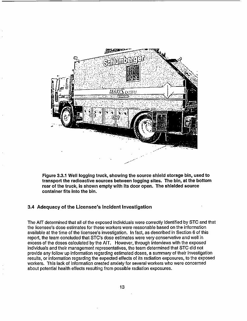
3.3.1 Well logging truck, showing the source shield storage bin, used to transportthe radioactive sources between logging sites. The bin, at the bottom rearof the truck, is shown empty with its door open. The shielded sourcecontainer fits into this bin ............ ............................. 13
5.3.2.1 Photographs of the source container shield plug showing the thin, flexible,cable/clamp assembly (left) and a more rigid replacement assembly (right) . . 21
6.2.2 Lymphocyte and platelet counts for one of the workers, worker D, fromblood samples taken at approximately weekly intervals starting about oneweek after the event ............ ................................. 27
7.1 Photograph of a microscope slide image showing a group of chromosomesand four, or possibly five, dicentrics, two of which are pointed out by thelines........................................................ 39
Tables
5.1 Sites visited by the AIT, including those within NRC's jurisdiction, inAgreement States, in Canada, Brazil, and the United Kingdom ..... ....... 17
6.2.3 Results of the cytogenetics tests for worker D as provided by the threecytogenetics laboratories. The first blood sample was drawn in earlyJune, and the second sample was drawn in early November .............. 29
6.3.1 Distance and time estimates based on time-and-motion interviews withthe exposed workers ........... ................................. 30
6.3.2 Results of 50-cm radius circumferential measurements and axialmeasurements of the source, and the corresponding dose calculations.The last column shows the doses along the axis of the source at a distanceof 37 cm . ...................................................... 32
6.3.3.1 Dose rates at different distances from the source ....................... 33
6.3.3.2 Dose estimates for each exposed worker based on data shown in Tables6.3.1 and 6.3.3.1. Doses shown are effective dose equivalents .... ........ 34
6.3.5.1 Most probable doses received by the workers on the drill rig ..... .......... 36
viii

TEAM MEMBERS
The following are the NRC Regional and Headquarters staff who were on the AugmentedInspection Team.
Dennis Boal, 01, Region IV Field Office
Robert Brown, Region IV
Richard Leonardi, Region IV
Mark Shaffer, Team Leader, Region IV
Sami Sherbini, NMSS, Headquarters
ix
ACKNOWLEDGMENTS
The team wishes to acknowledge the technical assistance provided by the following.
William Blakely, Ph.D., Armed Forces Radiobiological Research Institute, Bethesda, MD
Susanne Gollin, Ph.D., University of Pittsburgh Cancer Institute, Pittsburgh, PA
John Hunt, Ph.D., Comissdo National de Energia Nuclear, Rio de Janeiro, Brazil
David Lloyd, Ph.D., National Radiological Protection Board, Chilton, Didcot, Oxon, UK
Daniel Lundstrom, Precision Drilling, Nisku, Alberta, Canada
Pat Prasanna, Ph.D., Armed Forces Radiobiological Research Institute, Bethesda, Maryland
Adriana Ramalho, Ph.D. Comissfio National de Energia Nuclear, Rio de Janeiro, Brazil
Robert Ricks, M.D., Radiation Emergency Assistance Center/Training Site, Oak Ridge, TN
Neil Wald, M.D., University of Pittsburgh, Pittsburgh, PA
In addition to the individuals noted above, the AIT wishes to thank the many individuals whoprovided freely of their time, knowledge, and expertise to help the team complete its work.
xi
ABBREVIATIONS
AFRRI Armed Forces Radiobiological Research InstituteAIT Augmented Inspection Team
CDT Central Daylight TimeCFR Code of Federal RegulationscGy centigrayCi curiecSv centisievert
DOE Department of Energy
gBq gigabequerelGy gray
IMC Inspection Manual ChapterIP Inspection ProcedureIRD Instituto de Radioprotecao e DosimetriaISO International Organization for Standardization
LCM Loss Causation ModelLE Logging EngineerMCNP Monte Carlo N-ParticleMORT Management Oversight and Risk Tree
NMSS NRC Office of Nuclear Material Safety and SafeguardsNRC U.S. Nuclear Regulatory CommissionNRPB National Radiological Protection BoardNSSI Nuclear Source and Services, Inc.
01 NRC Office of InvestigationsORAU Oak Ridge Associated UniversitiesORISE Oak Ridge Institute for Science and Education
REAC/TS Radiological Emergency Assistance Center/Training SiteRSO Radiation Safety Officer
SOS Schlumberger Oilfield ServicesSTC Schlumberger Technology Corporation
TI Temporary Instruction
xiii

1 INTRODUCTION
1.1 Overview
This report describes the activities undertaken by the U.S. Nuclear Regulatory Commission's(NRC) Augmented Inspection Team (AIT) in connection with an incident involving the exposureof a number of members of the public to radiation doses that in some cases exceeded theNRC's dose limit for members of the public. The incident occurred on a drill rig in the State ofMontana on May 215', 2002, and was reported to the NRC on May 23i , 2002. NRC's initialresponse to the notification was to send a reactive inspection team to the site to determine thedetails of the incident. However, a blood test (cytogenetics) performed on one of the workerssuggested that the worker had been exposed to a radiation dose of the order of 2 gray (Gy)(200 rad), the inspection was upgraded to an AIT.
1.2 Use of Byproduct Material in Oil and Gas Well Logging
Well logging companies use instruments lowered into a hole drilled in the ground, called a well,to obtain information about underground rock formations, such as type of rock, porosity,density, and hydrocarbon content. The instruments are lowered into the well, which may befrom a few hundred to 30,000 feet deep, on a cable known as a wireline. The wireline carriesthe signals from the logging instruments to the surface for analysis. Information collected inthis manner is recorded and plotted on charts as the logging instruments are slowly raised fromthe bottom of the well. This information is studied and interpreted by experienced geologists orengineers to determine the likely presence and amounts of oil or gas. Sealed radioactivesources, together with associated radiation detectors, contained in logging tools, are one classof logging instruments frequently used to obtain information on the characteristics of rockformations. Amercium-241 (24'Am, typically 9.3 GBq (0.25 curie (Ci) to 740 GBq (20 Ci)) andcesium-1 37 (137CS, typically 3.7 to 110 GBq ( 0.1 to 3 Ci) are the radioactive materials mostfrequently used for this purpose.
As of December 2002, 35 companies possessed NRC licenses to use radioactive materials toperform well logging operations in the United States. There are also 211 Agreement Statelicensees authorized to conduct similar activities in Agreement States. Note that some welllogging companies possess both an NRC license as well as an Agreement State license.Therefore, the total number of licensed well logging companies in the United States is less thanthe sum of all NRC and Agreement State well logging licensees.
Schlumberger is a global technology services company with corporate offices in New York,Paris, and The Hague, and has more than 80,000 employees working in nearly 100 countries.One of the business segments of Schlumberger is Schlumberger Oilfield Services.Schlumberger Technology Corporation (STC) is a wholly owned subsidiary of SchlumbergerOilfield Services. STC is authorized by NRC License 42-00090-03 to use various radioisotopesin oil, gas, mineral, coal, ground water, and environmental well logging at temporary job sitesanywhere in the United States where the NRC maintains jurisdiction for regulating the use oflicensed material, including areas of exclusive Federal jurisdiction within Agreement States.STC also possesses multiple Agreement State licenses to conduct similar activities in variousAgreement States.
1
-
To help understand event descriptions provided in this report, the following is a brief descriptionof the job duties of some of the workers assigned to a typical well logging crew at STC. Inaddition, a glossary of other terms used in the report is also included in Appendix C.
Wireline Field Engineer
This individual is responsible for ensuring that the preparation and dispatching of equipment iscomplete, and that the service delivered at the well site, in terms of safety, quality, andefficiency of operations, is up to standard. The wireline field engineer is in charge of hisoperating cell (crew) and is responsible for the training and development of personnel assignedto his cell, and for the maintenance status of his assigned equipment.
Junior Field Engineer
This individual performs tasks, as assigned by the field engineer in charge of the crew, whichrelate directly to the loading and unloading of radioactive sources into the logging tool. Thisindividual also conducts radiation surveys as appropriate, and performs tasks directly related tocomputer processing of the data generated during wireline operations.
Senior Operator
This individual performs duties as required in the servicing of oil and gas wells and themaintenance and repair of service units and tools. Some of the many duties include (1)operating the winch for running in and out of the hole, (2) selecting, loading, and unloadingrequired tools and corresponding surface instrumentation for the job, and (3) assisting theengineers in maintenance checks of tools and equipment. The Senior operator does nothandle radioactive sources, but may be required to conduct radiation surveys after completionof logging operations, as directed by the field engineer in charge.
2
- l
2 SOURCE-RELATED EQUIPMENT USED IN WELL LOGGINGOPERATIONS
2.1 Overview
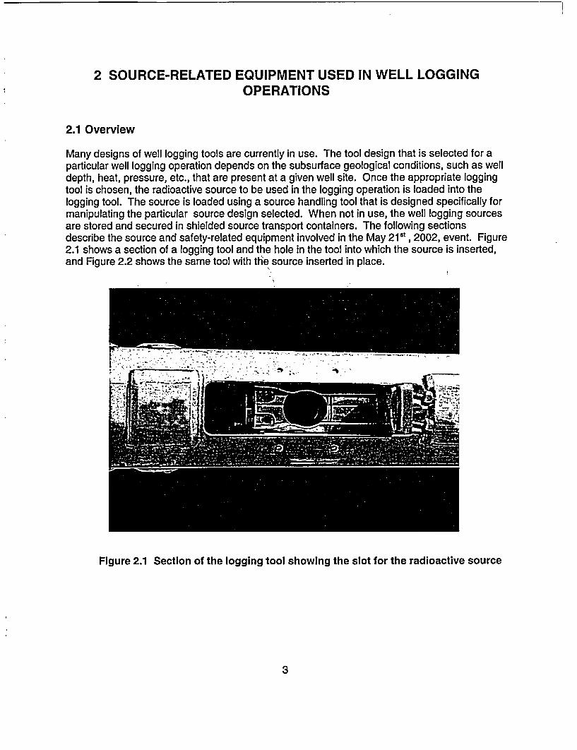
Many designs of well logging tools are currently in use. The tool design that is selected for aparticular well logging operation depends on the subsurface geological conditions, such as welldepth, heat, pressure, etc., that are present at a given well site. Once the appropriate loggingtool is chosen, the radioactive source to be used in the logging operation is loaded into thelogging tool. The source is loaded using a source handling tool that is designed specifically formanipulating the particular source design selected. When not in use, the well logging sourcesare stored and secured in shielded source transport containers. The following sectionsdescribe the source and safety-related equipment involved in the May 21St, 2002, event. Figure2.1 shows a section of a logging tool and the hole in the tool into which the source is inserted,and Figure 2.2 shows the same tool with thle source inserted in place.
rLn�jI' '... �
Figure 2.1 Section of the logging tool showing the slot for the radioactive source
3
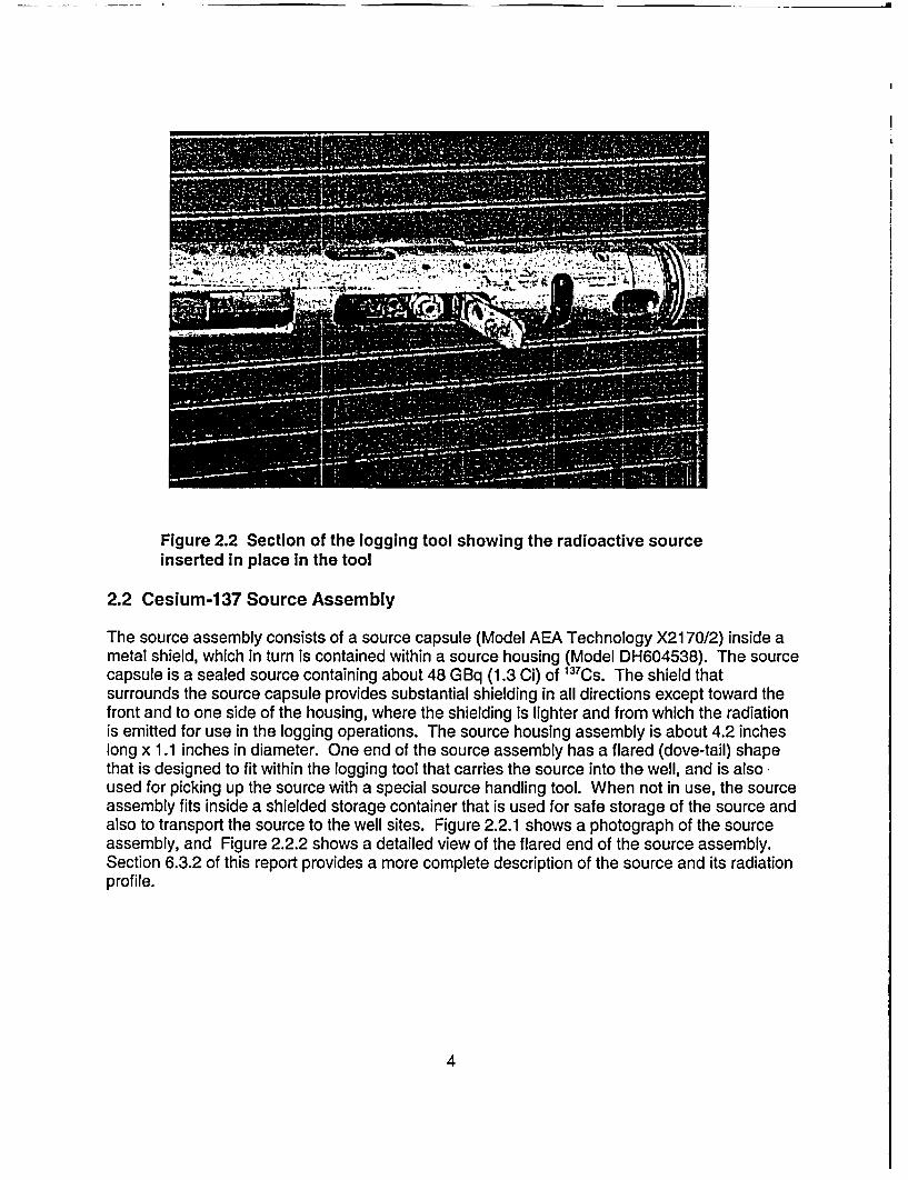
Figure 2.2 Section of the logging tool showing the radioactive sourceinserted in place In the tool
2.2 Cesium-137 Source Assembly
The source assembly consists of a source capsule (Model AEA Technology X2170/2) inside ametal shield, which in turn is contained within a source housing (Model DH604538). The sourcecapsule is a sealed source containing about 48 GBq (1.3 Ci) of 137Cs. The shield thatsurrounds the source capsule provides substantial shielding in all directions except toward thefront and to one side of the housing, where the shielding is lighter and from which the radiationis emitted for use in the logging operations. The source housing assembly is about 4.2 incheslong x 1.1 inches in diameter. One end of the source assembly has a flared (dove-tail) shapethat is designed to fit within the logging tool that carries the source into the well, and is alsoused for picking up the source with a special source handling tool. When not in use, the sourceassembly fits inside a shielded storage container that is used for safe storage of the source andalso to transport the source to the well sites. Figure 2.2.1 shows a photograph of the sourceassembly, and Figure 2.2.2 shows a detailed view of the flared end of the source assembly.Section 6.3.2 of this report provides a more complete description of the source and its radiationprofile.
4

hil*
1, '
Figure 2.2.1 A cesium-137 source similar to the one used In well loggingleft on the rig floor during the event
Figure 2.2.2 A detailed view of the flared end of the source assembly. Thebracket, with a hole into which the safety clip is inserted, is also shown.
5
2.3 Source Handling Tool
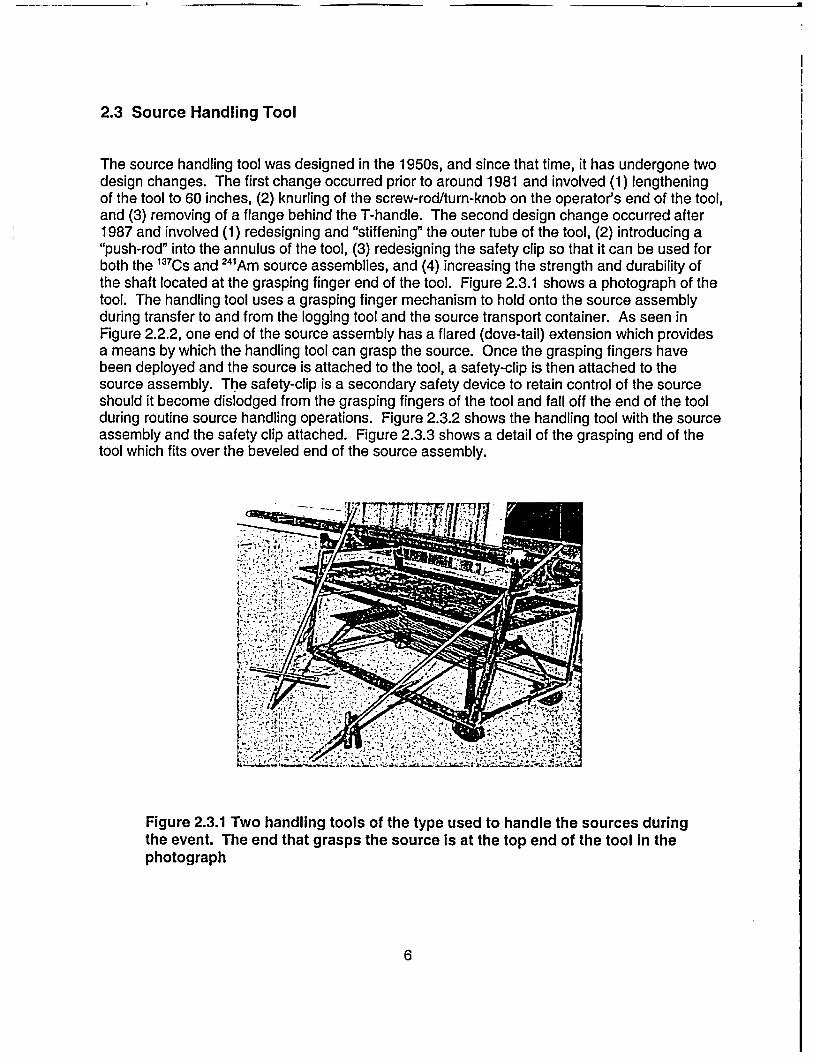
The source handling tool was designed in the 1950s, and since that time, it has undergone twodesign changes. The first change occurred prior to around 1981 and involved (1) lengtheningof the tool to 60 inches, (2) knurling of the screw-rod/turn-knob on the operator's end of the tool,and (3) removing of a flange behind the T-handle. The second design change occurred after1987 and involved (1) redesigning and "stiffening" the outer tube of the tool, (2) introducing a"push-rod" into the annulus of the tool, (3) redesigning the safety clip so that it can be used forboth the 13 7Cs and 24'Am source assemblies, and (4) increasing the strength and durability ofthe shaft located at the grasping finger end of the tool. Figure 2.3.1 shows a photograph of thetool. The handling tool uses a grasping finger mechanism to hold onto the source assemblyduring transfer to and from the logging tool and the source transport container. As seen inFigure 2.2.2, one end of the source assembly has a flared (dove-tail) extension which providesa means by which the handling tool can grasp the source. Once the grasping fingers havebeen deployed and the source is attached to the tool, a safety-clip is then attached to thesource assembly. The safety-clip is a secondary safety device to retain control of the sourceshould it become dislodged from the grasping fingers of the tool and fall off the end of the toolduring routine source handling operations. Figure 2.3.2 shows the handling tool with the sourceassembly and the safety clip attached. Figure 2.3.3 shows a detail of the grasping end of thetool which fits over the beveled end of the source assembly.
Figure 2.3.1 Two handling tools of the type used to handle the sources duringthe event. The end that grasps the source is at the top end of the tool in thephotograph
6

Figure 2.3.2 Source assembly attached to the end of the source toolwith the safety clip shown attached to the source
Figure 2.3.3 Detail showing the grasping lingers on the end of the sourcehandling tool. The fingers f it over the beveled end of the source assembly andare then tightened by the operator to grasp the beveled end. The knob in thecenter Is the plunger that is used to push the source off the tool when the fingersare released.
7
To secure a source to the source handling tool, the field engineer places the grasping fingers atthe end of the tool over the flared end of the source. He then screws the turn-knob to grasp thesource with the fingers. Once the fingers have been deployed and the source is attached to thetool, the source safety clip is attached to an eyelet on the end of the source. The source canthen be placed into the logging tool or source transport container as necessary. To detach thesource from the handling tool, the engineer reverses the screw-rod/turn-knob to release thesource, then employs the push-rod on the end of the tool to ensure that the source has beenreleased by the tool fingers. Finally, the engineer removes the source safety clip just prior tobacking the handling tool away from the source, and at the same time visually confirms that thehandling tool is detached from the source.
2.4 Shielded Source Storage/Transport Container
The shielded source storage/transport container (shield), shown in Figure 2.4.1, is an STCcustom-designed shielded container that weighs about 73 pounds. The container is designedsuch that it can be positioned straight up on its bottom or placed on its side for source loading.The container includes a shield plug insert that provides shielding above the source assembly,once the source is inserted inside the source cavity in the container. The plug insert is attachedto the container with a retaining cable. When the container is used in the vertical position, aswas done during the May 21 st, 2002, event, the plug assembly is designed to drop into thecontainer about 0.5 inch below the level of the container's neck, if the source assembly is not inthe container. This is clearly visible, and is designed to provide a visual indication to theoperator that the source is not in the container. The plug assembly will not drop in this mannerwhen the source is in the container, or if some other factor prevents its free fall into the sourcewell. Additionally, if the plug drops into the container, the locking mechanism for the containeris designed not to be operable without having to manually raise the plug out of the source wellto the proper position. This is another safety feature designed to alert the user to the absenceof the source within the container. Figure 2.4.2 shows the source assembly in place within thecontainer with the shield plug removed.
8

Figure 2.4.1 Top view of the source storage container with the shield plug in placeand locked. The cable attaching the plug to the body of the container is also seenin the photograph
Figure 2.4.2 Top view of the source storage container with the shield pilugremoved showing the source assembly in place within the container storage well
9
3 SUMMARY OF EVENTS
3.1 Licensee Event Report
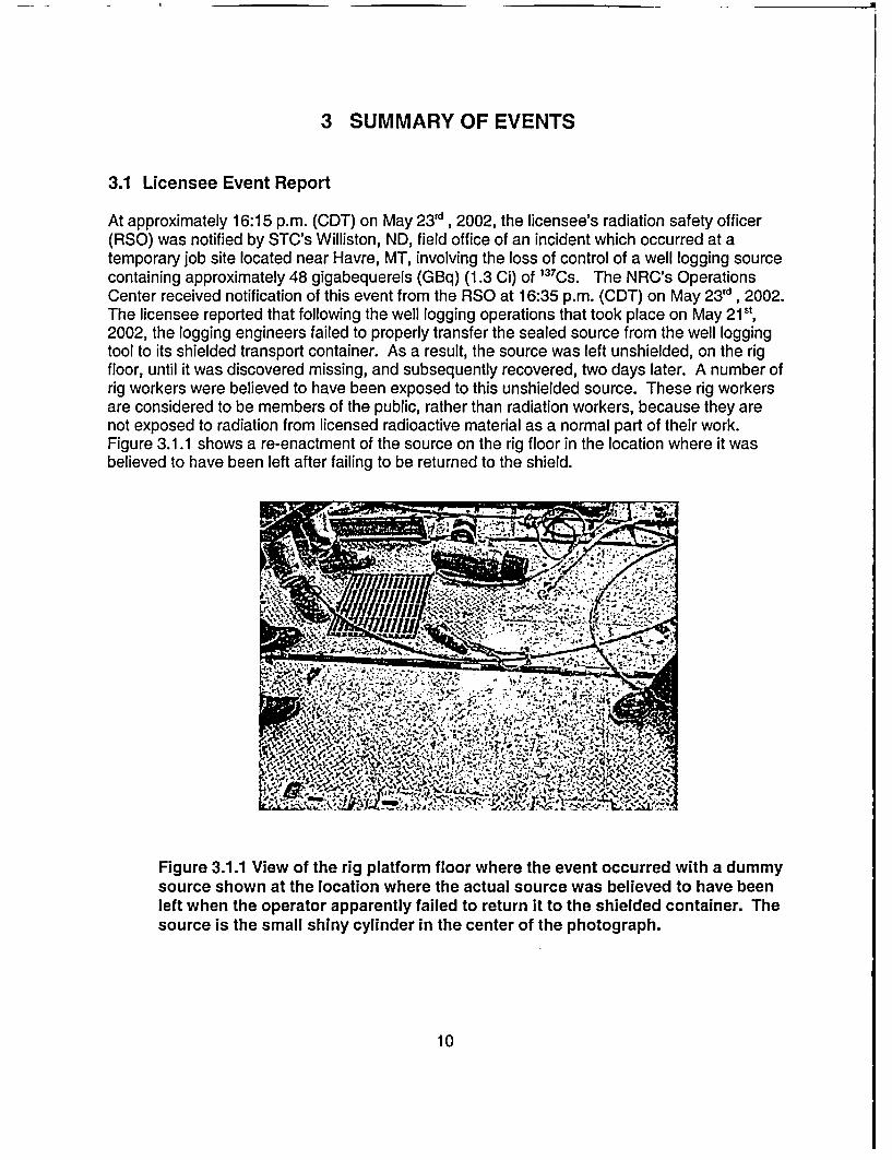
At approximately 16:15 p.m. (CDT) on May 23rd, 2002, the licensee's radiation safety officer(RSO) was notified by STC's Williston, ND, field office of an incident which occurred at atemporary job site located near Havre, MT, involving the loss of control of a well logging sourcecontaining approximately 48 gigabequerels (GBq) (1.3 Ci) of 1 37Cs. The NRC's OperationsCenter received notification of this event from the RSO at 16:35 p.m. (CDT) on May 23 Id , 2002.The licensee reported that following the well logging operations that took place on May 21s',2002, the logging engineers failed to properly transfer the sealed source from the well loggingtool to its shielded transport container. As a result, the source was left unshielded, on the rigfloor, until it was discovered missing, and subsequently recovered, two days later. A number ofrig workers were believed to have been exposed to this unshielded source. These rig workersare considered to be members of the public, rather than radiation workers, because they arenot exposed to radiation from licensed radioactive material as a normal part of their work.Figure 3.1.1 shows a re-enactment of the source on the rig floor in the location where it wasbelieved to have been left after failing to be returned to the shield.
Figure 3.1.1 View of the rig platform floor where the event occurred with a dummysource shown at the location where the actual source was believed to have beenleft when the operator apparently failed to return it to the shielded container. Thesource is the small shiny cylinder in the center of the photograph.
10
3.2 Licensee Follow Up to the Reported Event
Following recovery of the logging source, STC sent an investigation team composed ofemployees from management and safety positions to Montana, beginning the evening of May23d , 2002. Representatives from the drilling contractor and well operator also joined theinvestigation. The licensee interviewed numerous individuals, including 31 rig workers believedto have been exposed to radiation as a result of the loss of control of the 1 37 Cs source.
In a written report from the licensee, dated June 2 5th, 2002, STC provided NRC with updatedinformation regarding its investigation of the event. The licensee's investigation concluded that31 members of the public (rig workers) were exposed to radiation resulting from this event.STC believed it had sufficiently bounded the exposures to these individuals and calculated thehighest exposure to an individual to be approximately 6.4 centisievert (cSv) (6.4 rems). Tenworkers were estimated to have received exposures between 2 and 6.4 cSv (2 to 6.4 rem), 15individuals received exposures between 1 and 2 cSv (1 to 2 rem), and 6 individuals receivedexposures less than lcSv (1 rem). As a precautionary measure, blood tests were performedon 10 of the workers to check for lymphocyte depletion, an indicator of high radiation exposure.In addition, cytogenetic testing was initiated on one of the exposed workers.
STC's June 2 5th, 2002, report stated that the cause for the source being left on the rig floor wasdetermined to be a failure of the logging crew to follow standard operating procedures.Standard operating procedures required that multiple surveys with a radiation detection surveyinstrument be conducted to verify the presence of the source in its shielded container. None ofthese surveys were performed by the crew. Additionally, the licensee's investigation reportstated that STC's standard operating procedures were clearly understood by the crew, that theequipment used for source transfers at the well site was properly functioning, and that STC'sstandard operating procedures, had they been followed, would have prevented this incident.Further, the licensee concluded that STC's training program, the equipment used for sourcetransfers, and STC's procedures were all fundamentally sound.
The licensee's proposed corrective actions for this event included (1) terminating theemployment of the three logging crew members deemed responsible for the loss of control ofthe 137CS source, (2) sending an "STC Alert," describing the incident, to all STC logging facilitiesin the United States, (3) implementing a planned modification to the licensee's training programto provide more detailed and graphic information regarding potential injuries to individuals thatcould occur if logging sources are not adequately secured, and (4) implementing a plannedmodification to the licensee's training program to include additional emphasis on the legalresponsibilities of employees and managers and the potential penalties for individuals whoviolate company procedures.
3.3 NRC's Response to the Licensee's Event Report
In response to the licensee's telephonic report of the incident, a special, reactive inspection wasinitiated by NRC on May 25t, 2002, to examine the drill rig, witness interviews conducted by thelicensee with some of the potentially exposed individuals, and conduct independent interviewswith licensee personnel. Based on these initial interviews, and the interviews subsequentlyperformed by the AIT, a detailed sequence of events was developed, and is included asAppendix B of this report. However, the following is a brief description of what is believed to
11
have happened at the well site immediately after logging operations were completed on May21't, 2002.
Using a remote handling tool, a logging engineer removed the source assembly from the welllogging tool and attempted to place it in its shielded container. Assuming that the source wasproperly detached from the tool and properly housed in the source container, the engineer thenlocked the source shield plug in place. The team believes that, for reasons to be discussedlater in this report, the engineer was able to lock the source plug in place despite the fact thatthe source was not in the container, contrary to the intended safety function of this plug, whichhad failed. Had this function worked properly, it would have resulted in the plug falling insidethe source storage cavity, making it impossible to lock the plug in place without having to pull itout of the well, thereby alerting the engineer to the absence of the source. The AIT believesthe source was probably still attached to the handling tool when the engineer pulled the toolaway from the container. Then, when the engineer laid the handling tool down on the rig floor,the source probably fell off the tool and remained on the rig floor unnoticed by any of theworkers. Believing that the source was safely secured in its shielded container, the loggingcrew then removed the source container from the rig floor and placed it in the logging truck fortransport to the next job site. Figure 3.3.1 shows the location on the truck where the sourcecontainer is normally stored for transportation between logging sites. The logging crew did notperform any type of radiation survey to confirm that the source was indeed shielded andsecured. As a result, the 137Cs source remained unshielded on the drill rig floor until it wasrecovered by the licensee on the evening of May 23 d, 2002, approximately 56 hours later.
After the STC logging crew left the well site, the well was completed, the portable rig wasdismantled, moved to another drill site approximately 5 miles away, and there reassembled.Due to poor weather conditions, the rig remained at the new location, essentially unoccupied,for approximately 12 to 15 hours. However, during completion of the well and transfer to thenew well site, some of the drilling, casing, and cementing crew members worked in closeproximity of the radioactive source, possibly resulting in exposures in excess of NRC's 0.1 cSv(0.1 rem) annual dose limit to members of the public.
As indicated in Section 3.2 above, the licensee's initial assessments resulted in dose estimatesfor the rig workers ranging from less than 1 cSv to 6.4 cSv (1 to 6.4 rem). The AIT performedits own dose estimates for all of the exposed workers, and these showed that the licensee'sestimates were high by factors of up to about 10. The AlT's dose estimates ranged from closeto zero up to 1.3 cSv (1.3 rem). Blood counts and cytogenetic testing were also performed forsome of the workers, and these confirmed the dose estimates by failing to show indications ofhigh acute radiation exposures. Such negative test results indicate that, had the workers beenexposed to radiation, their doses must have been less than the sensitivity of these tests.Details of the dose estimates, both those of the licensee and AlT's, as well as discussions ofthe blood test results, are presented in Section 6 of this report.
12
- l
Figure 3.3.1 Well logging truck, showing the source shield storage bin, used totransport the radioactive sources between logging sites. The bin, at the bottomrear of the truck, is shown empty with its door open. The shielded sourcecontainer fits into the bin.
3.4 Adequacy of the Licensee's Incident Investigation
The AIT determined that all of the exposed individuals were correctly identified by STC and thatthe licensee's dose estimates for these workers were reasonable based on the informationavailable at the time of the licensee's investigation. In fact, as described in Section 6 of thisreport, the team concluded that STC's dose estimates were very conservative and well inexcess of the doses calculated by the AIT. However, through interviews with the exposedindividuals and their management representatives, the team determined that STC did notprovide any follow up information regarding estimated doses, a summary of their investigationresults, or information regarding the expected effects of its radiation exposures, to the exposedworkers. This lack of information created anxiety for several workers who were concernedabout potential health effects resulting from possible radiation exposures.
13
The team also reviewed the licensee's methodology for conducting incident investigations andSTC's determination of the causal factors related to this particular event. The licensee used the"Loss Causation Model" (LCM), developed by the International Loss Control Institute, as itsprimary investigation tool. The individuals who conducted interviews with the exposed workers,including the RSO and others involved in the investigation, had all received specialized trainingin this methodology. The RSO described the LCM method as a systematic analysis tool toidentify the system failures which cause incidents or "near incidents." The training slidesprovided to the team indicated that the fundamental principals of the LCM are (1) incidents donot just happen, (2) multiple causes usually contribute, (3) fixing immediate causes is notprevention, and basic (system) causes must be identified, (4) basic (system) causes arecreated by a lack of management control, and (5) plans of action must correct the basic causesand lack of control.
The team believes the LCM approach to be an adequate method for this case, and ifimplemented as designed, would focus the user toward discovery of contributing and rootcauses. Such causes, if properly addressed, can prevent similar incidents from occurring.However, the team identified weaknesses in the licensee's implementation of this method, as itwas implemented following this event, as well as its use following past similar events. Theseweaknesses are discussed in more detail in Section 5.
14

4 PRECURSOR EVENTS
Through interviews with STC and other well logging licensees, the team determined that welllogging sources do, periodically, fall off the handling tools during source transfers. However,these incidents are infrequent and when they do occur, the logging crews immediately identifythe fact that the source has become detached, and recovery of the source is accomplishedquickly. Although the number of these incidents is small in comparison to the total number ofsuccessful source transfers accomplished each day by well logging licensees, the risk ofunnecessary exposures, and of exposures exceeding NRC's dose limit to members of thepublic, is high whenever such an event occurs. The team discovered several instances, similarto the May 2002 event, in which STC logging personnel failed to identify the fact that thesources were improperly transferred to their shielded containers, and as a result, someworkers, who are considered members of the public in such cases, were unintentionallyexposed to radiation.
In addition to the May 215', 2002, event, the AIT discovered that the following six events, allinvolving STC personnel and equipment, occurred between 1987 and 2001 in the UnitedStates.
* In 1987, control of a 590 GBq (16 Ci) 241'Am neutron source was lost when, afterremoving the source from the logging tool, the engineer placed the handling tool, withthe source still attached, on the catwalk section of the drill rig and left the site. Thesource remained on the job site, unshielded, for approximately 1 day. The licensee'sinvestigation determined that a contributing cause was the failure of the engineer toperform a radiation survey of the source container or well area before leaving the site.
* In 1987, an event occurred involving the loss of control of a 63 GBq (1.7 Ci) ' 3 7Cs
source which was left on the rig floor, unshielded, for 4 days. The licensee's review ofthe incident determined that the logging engineer accidently pulled the source back outof the shield at the conclusion of the source transfer procedure. The licensee'sinvestigation determined that a contributing cause was the failure of the engineer toperform a radiation survey of the source container or well area before leaving the site.
* In 1990, loss of control of a 63 GBq (1.7 Ci) 137CS source occurred when the source wasleft on the rig floor, unshielded, for an undetermined period of time. The licensee'sinvestigation determined that the logging engineer accidently pulled the source back outof the shield at the conclusion of the source transfer procedure. The licensee'sinvestigation also determined that a contributing cause was the failure of the engineer toperform a radiation survey of the source container or well area before leaving the site.
* In 1991, an event occurred involving the loss of control of a 63 GBq (1.7 Ci) 137Cssource, which was left on the rig floor, unshielded, for 19 hours. The licensee's reviewof the incident determined that the logging engineer accidently pulled the source backout of the shield at the conclusion of the source transfer procedure. A contributingcause was the failure of the engineer to perform a radiation survey of the sourcecontainer or well area before leaving the site.
15
* In 1997, a 63 GBq ( 1.7 Ci) 137 Cs source was knocked off the end of the handling toolwhen the engineer lost his balance on the rig floor. The source fell into the well boreand was not recovered.
* In August 2001, an event occurred in Edinburgh, TX involving the loss of control of a 63GBq (1.7 Ci) 137 CS source which was left unshielded on the rig floor. This incidentresulted in 16 members of the public (drilling rig workers) receiving unnecessaryradiation exposures, seven of which received doses in excess of 0.1 cSv (0.1 rem). Thelicensee's review of the incident determined that the logging engineer accidently pulledthe source back out of the shield at the conclusion of the source transfer procedure. Acontributing cause was the failure of the engineer to perform a radiation survey of thesource container or well area before leaving the site.
The AIT requested that the licensee provide more detailed information regarding the eventsdescribed above, but STC was unable to find any records that could provide sufficientinformation regarding the specific locations for the events, the number of potentially exposedindividuals, or the estimated radiation doses resulting from these events. With the exception ofthe August 2001 event, dose estimates for potentially exposed individuals were not available.
16
5 DIRECT, CONTRIBUTING, AND ROOT CAUSES
5.1 Methods and Inspection Schedule
In selecting its methods for root cause analysis, the AIT used various analytical techniques,including Management Oversight and Risk Tree (MORT) analysis, to review human factors,equipment performance, and procedures, in an attempt to identify the casual factors related tothis event. The scope of the AlT's review included (1) interviews of STC personnel and otheroilfield contract personnel that were involved in the event, (2) a review of STC's sealed sourcehandling equipment and other related sealed source safety equipment, (3) a review of STC'sradiation safety training program for logging engineers, (4) a review of sealed source housingdesigns used by STC, as well as designs used by several other well logging companies, (5) areview of source handling tool designs used by STC as well as other designs used by severalwell logging companies, (6) a review of STC's inspection and maintenance program for sealedsources and safety related equipment, (7) direct observation of well logging operations attemporary job sites (oil/gas well sites) of STC and other well logging licensees, and (8) a reviewof STC's response to reported radiation incidents/events involving STC sealed sources,including a review of the licensee's corrective actions program.
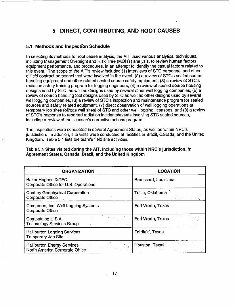
The inspections were conducted in several Agreement States, as well as within NRC'sjurisdiction. In addition, site visits were conducted at facilities in Brazil, Canada, and the UnitedKingdom. Table 5.1 lists the team's field site activities.
Table 5.1 Sites visited during the AIT, including those within NRC's jurisdiction, inAgreement States, Canada, Brazil, and the United Kingdom
ORGANIZATION LOCATION
Baker Hughes INTEQ Broussard, LouisianaCorporate Office for U.S. Operations
Century Geophysical Corporation Tulsa, OklahomaCorporate Office'
Comprobe, Inc. Well Logging Systems Fort Worth, TexasCorporate Office
Computalog U.S.A. Fort Worth,' TexasTechnology Services Group *_-_'
Halliburton Logging Services Fairfield, TexasTemporary Job Site
'Halliburton Energy Services - Houston, TexasNorth America Corporate Office -_'_'_':_-_ :
17

ORGANIZATION LOCATION
The Henry M. Jackson Foundation for the Rockville, MarylandAdvancement of Military Medicine, Inc.
National Radiological Protection Board Chilton, Didcot, Oxon,United Kingdom
National Nuclear Energy Corn mission Rio de Janeiro, BrazilInstitute for Radiation Protection and Dosimetry
Nuclear Sources and Services, Inc. Houston, TexasCorporate Office
Precision Drilling Nisku, AlbertaTechnical Support Center Canada
Probe Technology Services, Inc Fort Worth, TexasCorporate Office
Schlumberger Technology Corporation Roswell, New MexicoTemporary Job Site
Schlumberger Technology Corporation Artesia, New MexicoTemporary Job Site
Schlumberger Technology Corporation Sugar Land, TexasNorth America Corporate Office
Schlumberger Technology Corporation Corporate Kellyville, OklahomaTraining Facility
Schlumberger Technology Corporation Williston, North DakotaAuthorized Field Station
State of Texas Austin, TexasBureau of Radiation Control
State of Louisiana Baton Rouge, LouisianaDepartment of Environmental Quality
State of Oklahoma Oklahoma City, OklahomaDepartment of Environmental Quality
Tucker Technologies, Inc. Tulsa, OklahomaCorporate Office
U.S. Department of Energy Oak Ridge, TennesseeOak Ridge Institute for Science and EducationRadiation Emergency Assistance Center/Training Site
U.S. Department of Defense Bethesda, MarylandArmed Forces Radiobiological Research Institute
18
ORGANIZATION LOCATION
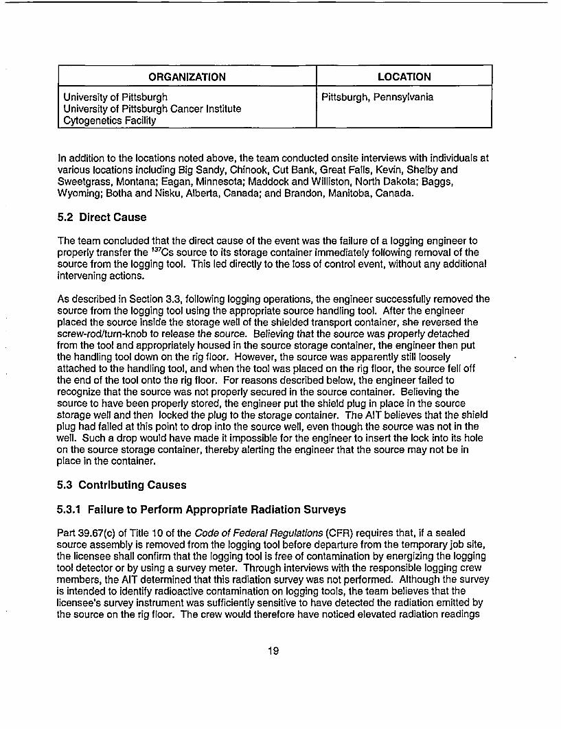
University of Pittsburgh Pittsburgh, PennsylvaniaUniversity of Pittsburgh Cancer InstituteCytogenetics Facility
In addition to the locations noted above, the team conducted onsite interviews with individuals atvarious locations including Big Sandy, Chinook, Cut Bank, Great Falls, Kevin, Shelby andSweetgrass, Montana; Eagan, Minnesota; Maddock and Williston, North Dakota; Baggs,Wyoming; Botha and Nisku, Alberta, Canada; and Brandon, Manitoba, Canada.
5.2 Direct Cause
The team concluded that the direct cause of the event was the failure of a logging engineer toproperly transfer the 137Cs source to its storage container immediately following removal of thesource from the logging tool. This led directly to the loss of control event, without any additionalintervening actions.
As described in Section 3.3, following logging operations, the engineer successfully removed thesource from the logging tool using the appropriate source handling tool. After the engineerplaced the source inside the storage well of the shielded transport container, she reversed thescrew-rod/turn-knob to release the source. Believing that the source was properly detachedfrom the tool and appropriately housed in the source storage container, the engineer then putthe handling tool down on the rig floor. However, the source was apparently still looselyattached to the handling tool, and when the tool was placed on the rig floor, the source fell offthe end of the tool onto the rig floor. For reasons described below, the engineer failed torecognize that the source was not properly secured in the source container. Believing thesource to have been properly stored, the engineer put the shield plug in place in the sourcestorage well and then locked the plug to the storage container. The AIT believes that the shieldplug had failed at this point to drop into the source well, even though the source was not in thewell. Such a drop would have made it impossible for the engineer to insert the lock into its holeon the source storage container, thereby alerting the engineer that the source may not be inplace in the container.
5.3 Contributing Causes
5.3.1 Failure to Perform Appropriate Radiation Surveys
Part 39.67(c) of Title 10 of the Code of Federal Regulations (CFR) requires that, if a sealedsource assembly is removed from the logging tool before departure from the temporary job site,the licensee shall confirm that the logging tool is free of contamination by energizing the loggingtool detector or by using a survey meter. Through interviews with the responsible logging crewmembers, the AIT determined that this radiation survey was not performed. Although the surveyis intended to identify radioactive contamination on logging tools, the team believes that thelicensee's survey instrument was sufficiently sensitive to have detected the radiation emitted bythe source on the rig floor. The crew would therefore have noticed elevated radiation readings
19
and would have been alerted to an unusual condition. They would most likely have discoveredthe cause of the elevated readings and found the unshielded source on the rig floor.
In addition to the logging tool survey, STC's standard operating procedures also require that a"post job survey" of the source container be conducted after a logging source is locked in thecontainer, and before the container is loaded back onto the logging truck. This requirement isintended to ensure that the source is in the container. Based on interviews with each of thethree individuals on the logging crew, as well as interviews with other rig workers on site whoobserved the logging engineers unload the 13 7 CS source, the team determined that a radiationsurvey of the source container was not performed after removing the source from the loggingtool and presumably storing it in the source container, nor was a survey done prior to departurefrom the job site. The team's interviews disclosed that a properly calibrated radiation detectionsurvey instrument, with the appropriate measurement range, was stored in the logging truckduring the entire logging operation, but was not removed from its storage location at any timewhile the STC crew was at the rig site. Of equal concern to the team was the fact that twomembers of the logging crew signed documentation (STC's "Hazardous Material ShippingPaper - Radiation") certifying to the following statement: "I have personally checked eachlogging source shield with a survey meter to ensure that the source is contained within."
The AIT determined that each of the three logging crew members had received appropriatetraining regarding radiation surveys of logging tools and source storage containers prior to theMay 2002 event. In addition, following a similar event that occurred in Texas during August2001, each of the three individuals recalled attending a training session in which they wereadvised of STC's new procedure requiring that a second, independent, radiation survey of eachsource storage container be performed prior to the container being loaded onto the loggingtruck. Prior to the August 2001 event, the radiation surveys were required to be performed byonly one of the logging engineers.
The team believes that if either one of the surveys described above had been properlyconducted, the logging crew would have been alerted to the fact that the source was notproperly shielded, which would have led to a more timely recovery of the source, therebyavoiding unnecessary exposures to workers. Therefore, the team concluded that the failure ofthe logging crew to perform a radiation survey of (1) the source storage container to verify thatthe logging source was in the properly shielded position, and (2) the logging tool immediatelyfollowing removal of the sealed sources, was a contributing cause of the event.
5.3.2 False Indication by Plug Assembly
As noted in Section 2.4, the source storage container used to house the 1 3 7CS source contains,as a secondary safety feature, a plug assembly designed to provide a visual indication to theengineer when a source is not housed in the container. Specifically, if a source is not in its placein the container, then the plug assembly is designed to fall into the source storage well in thecontainer and prevent the locking mechanism from working properly. STC's proceduresspecifically provide instruction to the engineers, stating, when a source is in the tool, the carryingcontainer must remain unlocked and the container must remain vertical so that the emptycontainer safety indicator works (lock shank cannot be inserted).
20
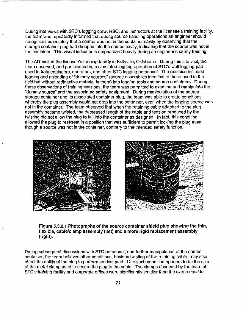
During interviews with STC's logging crew, RSO, and instructors at the licensee's training facility,the team was repeatedly informed that during source handling operations an engineer shouldrecognize immediately that a source was not in the container cavity by observing that thestorage container plug had dropped into the source cavity, indicating that the source was not inthe container. This visual indicator is emphasized heavily during an engineer's safety training.
The AIT visited the licensee's training facility in Kellyville, Oklahoma. During this site visit, theteam observed, and participated in, a simulated logging operation at STC's well logging padused to train engineers, operators, and other STC logging personnel. The exercise includedloading and unloading of "dummy sources" (source assemblies identical to those used in thefield but without radioactive material in them) into logging tools and source containers. Duringthese observations of training sessions, the team was permitted to examine and manipulate the"dummy source" and the associated safety equipment. During manipulation of the sourcestorage container and its associated container plug, the team was able to create conditionswhereby the plug assembly would not drop into the container, even when the logging source wasnot in the container. The team observed that when the retaining cable attached to the plugassembly became twisted, the decreased length of the cable and tension produced by thetwisting did not allow the plug to fall into the container as designed. In fact, this conditionallowed the plug to rest/seat in a position that was sufficient to permit locking the plug eventhough a source was not in the container, contrary to the intended safety function.
Figure 5.3.2.1 Photographs of the source container shield plug showing the thin,flexible, cable/clamp assembly (left) and a more rigid replacement assembly(right).
During subsequent discussions with STC personnel, and further manipulation of the sourcecontainer, the team believes other conditions, besides twisting of the retaining cable, may alsoaffect the ability of the plug to perform as designed. One such condition appears to be the sizeof the metal clamp used to secure the plug to the cable. The clamps observed by the team atSTC's training facility and corporate offices were significantly smaller than the clamp used to
21
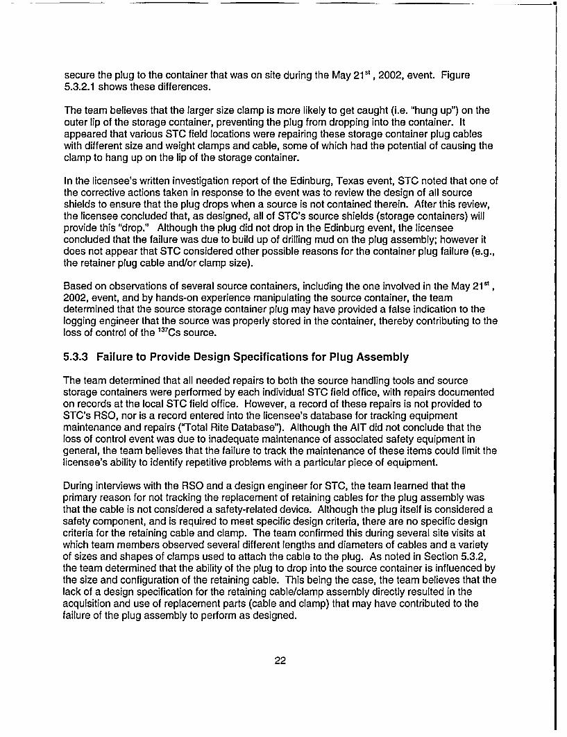
secure the plug to the container that was on site during the May 215s, 2002, event. Figure5.3.2.1 shows these differences.
The team believes that the larger size clamp is more likely to get caught (i.e. "hung up") on theouter lip of the storage container, preventing the plug from dropping into the container. Itappeared that various STC field locations were repairing these storage container plug cableswith different size and weight clamps and cable, some of which had the potential of causing theclamp to hang up on the lip of the storage container.
In the licensee's written investigation report of the Edinburg, Texas event, STC noted that one ofthe corrective actions taken in response to the event was to review the design of all sourceshields to ensure that the plug drops when a source is not contained therein. After this review,the licensee concluded that, as designed, all of STC's source shields (storage containers) willprovide this "drop." Although the plug did not drop in the Edinburg event, the licenseeconcluded that the failure was due to build up of drilling mud on the plug assembly; however itdoes not appear that STC considered other possible reasons for the container plug failure (e.g.,the retainer plug cable and/or clamp size).
Based on observations of several source containers, including the one involved in the May 215',2002, event, and by hands-on experience manipulating the source container, the teamdetermined that the source storage container plug may have provided a false indication to thelogging engineer that the source was properly stored in the container, thereby contributing to theloss of control of the 137 CS source.
5.3.3 Failure to Provide Design Specifications for Plug Assembly
The team determined that all needed repairs to both the source handling tools and sourcestorage containers were performed by each individual STC field office, with repairs documentedon records at the local STC field office. However, a record of these repairs is not provided toSTC's RSO, nor is a record entered into the licensee's database for tracking equipmentmaintenance and repairs ("Total Rite Database"). Although the AIT did not conclude that theloss of control event was due to inadequate maintenance of associated safety equipment ingeneral, the team believes that the failure to track the maintenance of these items could limit thelicensee's ability to identify repetitive problems with a particular piece of equipment.
During interviews with the RSO and a design engineer for STC, the team learned that theprimary reason for not tracking the replacement of retaining cables for the plug assembly wasthat the cable is not considered a safety-related device. Although the plug itself is considered asafety component, and is required to meet specific design criteria, there are no specific designcriteria for the retaining cable and clamp. The team confirmed this during several site visits atwhich team members observed several different lengths and diameters of cables and a varietyof sizes and shapes of clamps used to attach the cable to the plug. As noted in Section 5.3.2,the team determined that the ability of the plug to drop into the source container is influenced bythe size and configuration of the retaining cable. This being the case, the team believes that thelack of a design specification for the retaining cable/clamp assembly directly resulted in theacquisition and use of replacement parts (cable and clamp) that may have contributed to thefailure of the plug assembly to perform as designed.
22

In addition, although the licensee had indications from previous events that the plug assemblydoes not always function as designed, it does not appear that STC performed an adequateequipment failure analysis of the plug insert assembly. Specifically, aside from dirt/debris buildup on the plug, the licensee did not consider other failure modes, such as the influence of theretaining cable. This limited equipment failure analysis probably also contributed to thecontinued practice of using replacement parts (cable and clamp) that may have been differentfrom those in the system design, thereby defeating the intended safety function of the plugassembly, which appeared to work reliably, and as intended, only when the proper parts wereused.
5.4 Root Cause(s)
The team identified as a possible root cause of the event the failure of the licensee toadequately investigate precursor events to determine their underlying causes. Instead, thelicensee focused primarily on the direct cause of events and not on factors whose existencemade recurrent events more probable. Section 3.4 of this report described the licensee'sinvestigation and follow up actions taken in response to the May 21St, 2002, event. The teamconcluded that STC failed to execute a proper root cause analysis for this event, and likelyperformed a similar, limited review following other precursor events. As a result, the licenseecontinued to focus its corrective actions on the direct cause of events and fell short ofaddressing the root cause of why the errors continue to happen. Although the team agrees withthe licensee that a proper radiation survey of the source container would have likely preventedthe exposures to members of the public, it appears that STC's investigation(s) did not focussufficient attention toward identifying other possible contributing causes, systems failures, and/ormanagement controls that could prevent mishandling of sources, improper use of safetyequipment, and the underlying reason(s) why logging engineers continue to fail to conductradiation surveys and follow other standard operating procedures.
Also noted earlier in this report was that, in addition to the May 21 st, 2002, event, the licenseeexperienced six other similar events between 1987 and 2001 involving the loss of control oflogging sources. Five of these events resulted in unnecessary exposures to members of thepublic (unmonitored drilling rig workers). In each of these cases, STC concluded that the causeof the events was the failure of logging personnel to follow procedures. Although STC indicatedthat its evaluation of the May 21 5', 2002, event and other similar events, included a review ofpeople, equipment, and procedures, the team believes that these evaluations were deficient, inthat the review of these areas appears to have been performed independently of each other.Specifically, it appears that (1) STC's application of its root cause analysis method did notrecognize ugeneric" issues; causes that were identified were treated as unique (no trending oradequate root cause performed), (2) STC's application of its root cause analysis method failedto consider the contributions of its management and supervision systems on the occurrence ofan event, (3) STC's corrective actions appeared to focus on the use of disciplinary action ofemployees for events with repetitive causes (employee error), rather than performing a more in-depth evaluation of human error, (4) the licensee's program did not contain the requirement tomonitor corrective actions after they were implemented to determine if these actions wereeffective, and (5) STC's corrective actions program appears to rely on the use of lower tiercorrective measures (procedural changes, awareness, and safety warnings) in lieu of the moreeffective use of safety devices and/or design changes that are higher on the "safety precedencesequence."
23
The team believes that the licensee's limited review of precursor events established theconditions that allowed contributing causes to develop which, in turn, increased the probability ofthe occurrence of future incidents.
24
6 RADIOLOGICAL DOSE EVALUATIONS
6.1 Overview
The licensee's initial dose calculations for the workers who may have been exposed to the we!!logging source on the drilling rig were preliminary estimates because details of the exposureconditions were not known in detail at that time. Thus, the methods used for the dosecalculations were necessarily simplified. These calculations indicated doses that weresignificantly above NRC's dose limit of 0.1 cSv (0.1 rem) per year for members of the public, andwere in some cases slightly above NRC's occupational dose limit of 5 cSv (5 rem) per year.Such dose levels would constitute violations of regulatory requirements, but are not consideredto pose any immediate threat to the health of the workers. The dose estimates were believed bythe licensee to indicate upper limits of possible doses, due to the conservative assumptions usedin the calculations.
Because of the uncertainties involved in the initial calculations, and because there were noradiation measurements available at the time of the exposures, the licensee decided tosupplement the preliminary dose estimates with other methods that would bound the possibledoses received. These methods fall into the area known as biological dosimetry. Radiationexposures above a certain threshold level are known to produce clinically observable and otherphysiological effects, and the nature of these effects, as well as the time of their appearancefollowing exposure to radiation, can be used to estimate the dose received. Absence of thesebiological indicators provides assurance that the doses received were at least below thethresholds at which these indicators manifest themselves.
Because biological dosimetry methods have relatively high dose thresholds, below which they donot provide indications of radiation exposure, these tests were used in this case only to rule outhigh doses. Accurate assessments of the doses received in this case relied on calculationswhich, assuming reasonably accurate input data on durations of exposure and distances fromthe source, will yield good dose estimates. The following sections detail the efforts made to usebiological estimators of dose and describe the dose calculations made.
6.2 Biological Indicators of Dose
Acute radiation exposures (i.e., exposures in which the radiation dose is received over arelatively short period of time, usually less than 1 day) produce physiological and clinical effectsif the dose is sufficiently high. The biological effects of significance in this case are prodromalsymptoms, circulating blood cell depletion, and the appearance of aberrations in thechromosomes of the exposed person's circulating lymphocytes.
6.2.1 Prodromal Effects
These effects include nausea, vomiting, anorexia, fatigue, and weakness. They appear within aday or less of the radiation exposure and clear spontaneously within a day or so if the dose isnot very high. The severity of these effects, and the probability of their appearance, isproportional to the whole body dose received. Experience has demonstrated that they areunlikely if the whole body dose is below a certain threshold, on the order of about 50 cGy (50
25

-----
rads). None of the exposed workers in this case reported any symptoms within the first few daysafter exposure that may have been indicative of prodromal effects. On that basis the AIT, inconsultation with REAC/TS, concluded that any doses the workers may have received wereprobably lower than an equivalent whole body dose of about 50 cGy (50 rads). This isconsistent with the results of the licensee's preliminary dose estimates, which indicated doseswell below the threshold for prodromal effects.
6.2.2 Blood Cell Depletion
Circulating blood cells are sensitive to radiation exposure, and high doses of radiation will causea decrease in the number of these cells in circulation. Among the most sensitive of thecirculating cells to radiation effects are the lymphocytes and the platelets. The drop in blood cellcounts is expected to be only slight for doses in the range of 50 to 100 cGy (50 to 100 rads). Asa precautionary measure, the licensee recommended that the exposed workers provide bloodsamples to determine circulating blood cell levels. Ten of the workers did provide such samples,and the results were sent to the Radiological Emergency Assistance Center/Training Site(REAC/TS) for evaluation. REAC/TS did not find any indications of radiation exposure based onits examination of the blood sample results for these workers. This conclusion is consistent withthe results of the preliminary dose estimates, which indicated doses well below the threshold.
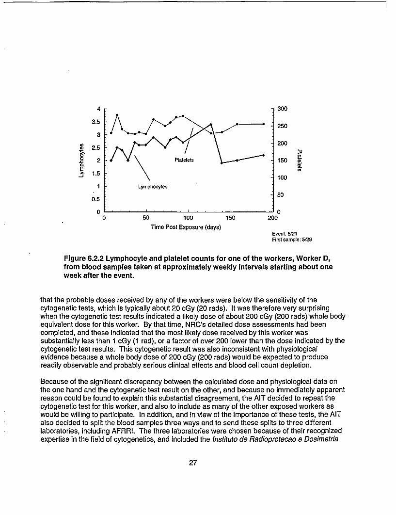
In addition to the one-time blood counts done for the 10 workers, one of the workers, who will bereferred to here as worker D, decided on his own initiative to continue testing his blood on aweekly basis. Figure 6.2.2 shows the results of these tests, demonstrating the variations inlymphocyte and platelet counts over a period of several months. REAC/TS also reviewed theseresults and concluded that they were consistent with an absence of an acute radiation exposurebecause they do not show the typical rapid drop in blood cell counts, followed by a slowrecovery, that is characteristic of acute radiation exposure. This does not mean that no radiationexposure occurred, but only that any whole body dose that may have been received was lessthan the level that would produce an observable blood cell and platelet count drop.
6.2.3 Cytogenetic Tests
In addition to the above effects of acute radiation exposure, ionizing radiation will also producecharacteristic defects in the chromosomes of the exposed person. A sensitive method ofobserving these defects is by examining the chromosomes in the person's circulatinglymphocytes. The defect of particular interest in quantifying radiation dose by this method iscalled a dicentric. This defect can be observed by microscopic examination of the cells aftersuitable culturing followed by microscope slide preparation and staining. Calibration curvesallow conversion of the observed dicentric frequency into an equivalent whole body radiationdose.
In order to substantiate the results of the blood count tests, the licensee decided to submit ablood sample from one of the exposed workers for cytogenetic testing: a sample from one ofthese workers, worker D, was sent to the Armed Forces Radiobiology Research Institute(AFRRI) for analysis. This was the same worker whose blood counts are shown in Figure 6.2.2.The licensee expected that the results would be negative because the preliminary dosecalculations, as well as the absence of any clinical and physiological symptoms, indicated
26
4 300
3 0
200a 2.5 -2
0. ° 2 \Platelets 150 CD
E1.5 100
1 Lymphocytes
500.5
0 . . . . . . . .00 50 100 150 200
Time Post Exposure (days)Event: W/21First sample: 5/29
Figure 6.2.2 Lymphocyte and platelet counts for one of the workers, Worker D,from blood samples taken at approximately weekly Intervals starting about oneweek after the event.
that the probable doses received by any of the workers were below the sensitivity of thecytogenetic tests, which is typically about 20 cGy (20 rads). It was therefore very surprisingwhen the cytogenetic test results indicated a likely dose of about 200 cGy (200 rads) whole bodyequivalent dose for this worker. By that time, NRC's detailed dose assessments had beencompleted, and these indicated that the most likely dose received by this worker wassubstantially less than 1 cGy (1 rad), or a factor of over 200 lower than the dose indicated by thecytogenetic test results. This cytogenetic result was also inconsistent with physiologicalevidence because a whole body dose of 200 cGy (200 rads) would be expected to producereadily observable and probably serious clinical effects and blood cell count depletion.
Because of the significant discrepancy between the calculated dose and physiological data onthe one hand and the cytogenetic test result on the other, and because no immediately apparentreason could be found to explain this substantial disagreement, the AIT decided to repeat thecytogenetic test for this worker, and also to include as many of the other exposed workers aswould be willing to participate. In addition, and in view of the importance of these tests, the AITalso decided to split the blood samples three ways and to send these splits to three differentlaboratories, including AFRRI. The three laboratories were chosen because of their recognizedexpertise in the field of cytogenetics, and included the Instituto de Radioprotecao e Dosimetria
27

(IRD) in Rio de Janeiro, Brazil, and the National Radiological Protection Board (NRPB) inChilton, United Kingdom.
Seven workers agreed to participate in the cytogenetic testing, including worker D. In addition,two control samples were obtained, one from an individual active in the oil/gas drilling industry,but who was not present at the site of this event, and the other sample was taken from the teamleader of this AIT. The blood was collected at clinics in three locations, Shelby, Montana, USA;Edmonton, Alberta, Canada; and Brandon, Manitoba, Canada. The AIT sent three sets ofsampling kits to each of the three blood collection locations, and the split blood samples werepackaged in the three kits at each site, together with ice packs and dosimeters provided byNRC. AFRRI provided the blood sampling kits, which contained all the medical supplies neededto draw blood samples, including disposable needles, sterile pads, sterile blood collection vialscontaining lithium heparin anti-coagulant, ice packs, medical release forms, and instructions. AnNRC representative was present at each blood collection site to ensure proper collection,labeling, and packaging procedures. The onsite NRC representatives also shipped thepackaged samples immediately by air, sending three kits to each of the three laboratories.Unfortunately, the samples shipped to Brazil were held up in Brazilian customs and could not bereleased in time for the blood to be analyzed before it degraded. The other two laboratoriesreceived their samples promptly and were able to analyze them.
The results of this second round of testing, as reported by the laboratory at NRPB, werenegative, that is, they showed zero dose at the level of sensitivity of the tests, for all but one ofthe workers, worker D. This was the same worker whose blood was initially tested at AFRRI.The results from NRPB for worker D indicated a slightly elevated dicentric frequency of 2dicentrics per 1,000 cells scored, compared with normal background, which is typically 1dicentric per 1,000 cells scored. This level of aberration corresponds to an equivalent wholebody radiation dose in the range of 0 to 14 cGy (0 to 14 rad), with a mean of 4 cGy (4 rad). Thecalculated dose for this worker for this event is lower than 4 cGy (4 rad), but is consistent withthe cytogenetic result, which includes zero dose as a possible exposure level. The results fromAFRRI agreed with those of NRPB for all the workers, that is, negative results, except for workerD, for whom AFRRI has not yet formally reported a dose estimate.
In addition to the above tests, the AIT had the microscope slides from NRPB's tests for worker Dsent to IRD in Brazil for evaluation, and the slides from AFRRI's second blood test for worker Dalso sent to IRD for evaluation. The AIT also sent AFRRI's slides from the first blood test toNRPB for evaluation. Table 6.2.3 summarizes the results of these rounds of tests andevaluations. The table shows the results in dicentric frequency rather than dose because thismakes the comparison between laboratory results more accurate by eliminating differences thatmay rise as a result of the use of different calibration curves by the different laboratories. Thedoses in cGy are very roughly equal to the numbers of dicentrics shown in the table. The resultsof the cytogenetics assessments by IRD and NRPB are consistent with the physiological dataand also with the dose calculations. The elevated results from AFRRI are not consistent with theavailable data, but the reason for this is still under study at AFRRI.
28
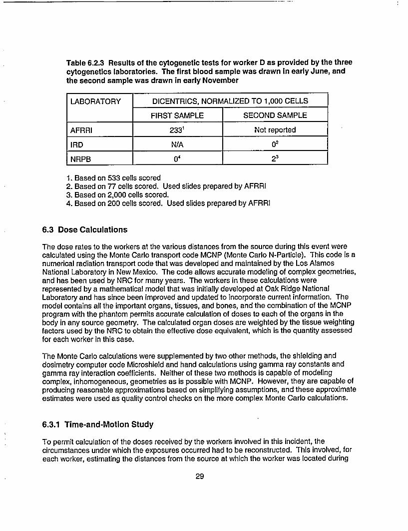
Table 6.2.3 Results of the cytogenetic tests for worker D as provided by the threecytogenetics laboratories. The first blood sample was drawn In early June, andthe second sample was drawn in early November
LABORATORY DICENTRICS, NORMALIZED TO 1,000 CELLS
FIRST SAMPLE SECOND SAMPLE
AFRRI 233' Not reported
IRD N/A o2
NRPB _ 23__
1. Based on 533 cells scored2. Based on 77 cells scored. Used slides prepared by AFRRI3. Based on 2,000 cells scored.4. Based on 200 cells scored. Used slides prepared by AFRRI
6.3 Dose Calculations
The dose rates to the workers at the various distances from the source during this event werecalculated using the Monte Carlo transport code MCNP (Monte Carlo N-Particle). This code is anumerical radiation transport code that was developed and maintained by the Los AlamosNational Laboratory in New Mexico. The code allows accurate modeling of complex geometries,and has been used by NRC for many years. The workers in these calculations wererepresented by a mathematical model that was initially developed at Oak Ridge NationalLaboratory and has since been improved and updated to incorporate current information. Themodel contains all the important organs, tissues, and bones, and the combination of the MCNPprogram with the phantom permits accurate calculation of doses to each of the organs in thebody in any source geometry. The calculated organ doses are weighted by the tissue weightingfactors used by the NRC to obtain the effective dose equivalent, which is the quantity assessedfor each worker in this case.
The Monte Carlo calculations were supplemented by two other methods, the shielding anddosimetry computer code Microshield and hand calculations using gamma ray constants andgamma ray interaction coefficients. Neither of these two methods is capable of modelingcomplex, inhomogeneous, geometries as is possible with MCNP. However, they are capable ofproducing reasonable approximations based on simplifying assumptions, and these approximateestimates were used as quality control checks on the more complex Monte Carlo calculations.
6.3.1 Time-and-Motion Study
To permit calculation of the doses received by the workers involved in this incident, thecircumstances under which the exposures occurred had to be reconstructed. This involved, foreach worker, estimating the distances from the source at which the worker was located during
29
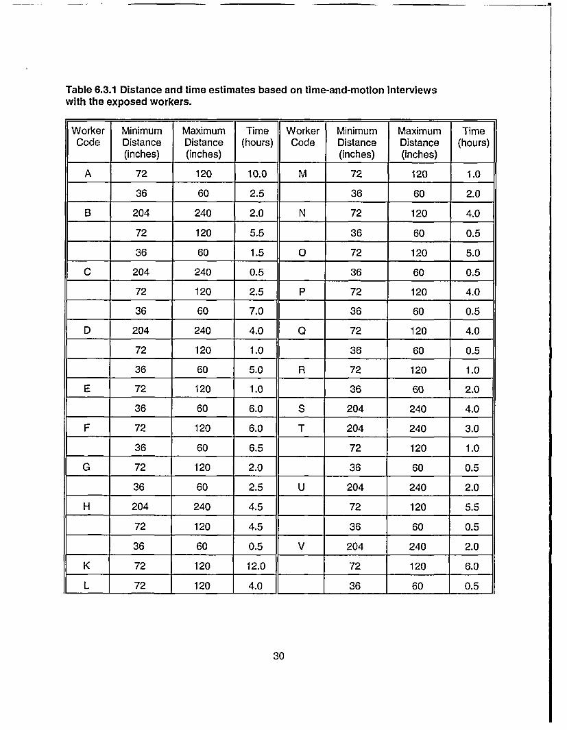
Table 6.3.1 Distance and time estimates based on time-and-motion interviewswith the exposed workers.
Worker Minimum Maximum Time Worker Minimum Maximum TimeCode Distance Distance (hours) Code Distance Distance (hours)
(inches) (inches) (inches) (inches)
A 72 120 10.0 M 72 120 1.0
36 60 2.5 36 60 2.0
B 204 240 2.0 N 72 120 4.0
72 120 5.5 36 60 0.5
36 60 1.5 0 72 120 5.0
C 204 240 0.5 36 60 0.5
72 120 2.5 P 72 120 4.0
36 60 7.0 36 60 0.5
D 204 240 4.0 a 72 120 4.0
72 120 1.0 36 60 0.5
36 60 5.0 R 72 120 1.0
E 72 120 1.0 36 60 2.0
36 60 6.0 S 204 240 4.0
F 72 120 6.0 T 204 240 3.0
36 60 6.5 72 120 1.0
G 72 120 2.0 36 60 0.5
36 60 2.5 U 204 240 2.0
H 204 240 4.5 72 120 5.5
72 120 4.5 36 60 0.5
36 60 0.5 V 204 240 2.0
K 72 120 12.0 72 120 6.0
L 72 120 4.0 36 60 0.5
30
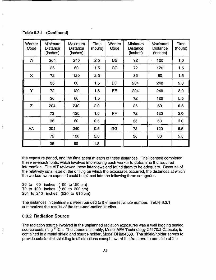
Table 6.3.1 - (Continued)
Worker Minimum Maximum Time Worker Minimum Maximum TimeCode Distance Distance (hours) Code Distance Distance (hours)
(inches) (inches) (inches) (inches)
W 204 240 2.5 BB 72 120 1.0
36 60 1.5 CC 72 120 1.5
X 72 120 2.5 36 60 1.5
36 60 1.5 DD 204 240 2.0
Y 72 120 1.5 EE 204 240 3.0
36 60 1.5 72 120 5.5
Z 204 240 2.0 36 60 0.5
72 120 1.0 FF 72 120 2.0
36 60 0.5 36 60 3.0
AA 204 240 0.5 GG 72 120 6.5
72 120 3.0 36 60 5.5
36 60 1.5 ___ I
the exposure period, and the time spent at each of these distances. The licensee completedthese re-enactments, which involved interviewing each worker to determine the requiredinformation. The AIT reviewed these interviews and found them to be adequate. Because ofthe relatively small size of the drill rig on which the exposures occurred, the distances at whichthe workers were exposed could be placed into the following three categories.
36 to 60 inches72 to 120 inches204 to 240 inches
( 90 to 150 cm)(180 to 300 cm)
(520 to 610 cm)
The distances in centimeters were rounded to the nearest whole number. Table 6.3.1summarizes the results of the time-and-motion studies.
6.3.2 Radiation Source
The radiation source involved in the unplanned radiation exposures was a well logging sealedsource containing 13 7Cs. The source assembly, Model AEA Technology X2170/2 Capsule, iscontained in a metal shield and source holder, Model DH604538. The shield/holder serves toprovide substantial shielding in all directions except toward the front and to one side of the
31
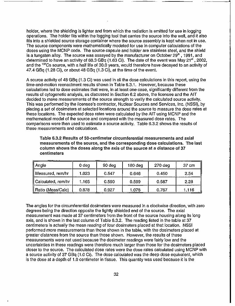
holder, where the shielding is lighter and from which the radiation is emitted for use in loggingoperations. The holder fits within the logging tool that carries the source into the well, and it alsofits into a shielded source storage container where the source assembly is kept when not in use.The source components were mathematically modeled for use in computer calculations of thedoses using the MCNP code. The source capsule and holder are stainless steel, and the shieldis a tungsten alloy. The source was assayed by the manufacturer on October 29 h , 1991, anddetermined to have an activity of 60.3 GBq (1.63 Ci). The date of the event was May 215', 2002,and the 13 7CS source, with a half life of 30.0 years, would therefore have decayed to an activity of47.4 GBq (1.28 Ci), or about 48 GBq (1.3 Ci), at the time of the event.
A source activity of 48 GBq (1.3 Ci) was used in all the dose calculations in this report, using thetime-and-motion reenactment results shown in Table 6.3.1. However, because thesecalculations led to dose estimates that were, in at least one case, significantly different from theresults of cytogenetic analysis, as discussed in Section 6.2 above, the licensee and the AITdecided to make measurements of the source strength to verify the calculated source activity.This was performed by the licensee's contractor, Nuclear Sources and Services, Inc. (NSSI), byplacing a set of dosimeters at selected locations around the source to measure the dose rates atthese locations. The expected dose rates were calculated by the AIT using MCNP and themathematical model of the source and compared with the measured dose rates. Thecomparisons were then used to estimate a source activity. Table 6.3.2 shows the results ofthese measurements and calculations.
Table 6.3.2 Results of 50-centimeter circumferential measurements and axialmeasurements of the source, and the corresponding dose calculations. The lastcolumn shows the doses along the axis of the source at a distance of 37centimeters
Angle 0 deg 90 deg 180 deg 270 deg 37 cm
Measured, rem/hr 1.023 0.547 0.646 0.450 2.54
Calculated, rem/hr 1.165 0.590 0.599 0.587 2.28
Ratio (Meas/Calc) 0.878 0.927 1.078 0.767 1.116
The angles for the circumferential dosimeters were measured in a clockwise direction, with zerodegrees being the direction opposite the lightly shielded end of the source. The axialmeasurement was made at 37 centimeters from the front of the source housing along its longaxis, and is shown in the last column of Table 6.3.2. The reading listed in the table at 37centimeters is actually the mean reading of four dosimeters placed at that location. NSSIperformed more measurements than those shown in the table, with the dosimeters placed atgreater distances from the source than those shown. However, the results of thesemeasurements were not used because the dosimeter readings were fairly low and theuncertainties in these readings were therefore much larger than those for the dosimeters placedcloser to the source. The calculated dose rates were the dose rates calculated using MCNP witha source activity of 37 GBq (1.0 Ci). The dose calculated was the deep dose equivalent, whichis the dose at a depth of 1.0 centimeter in tissue. This quantity was used because it is the
32
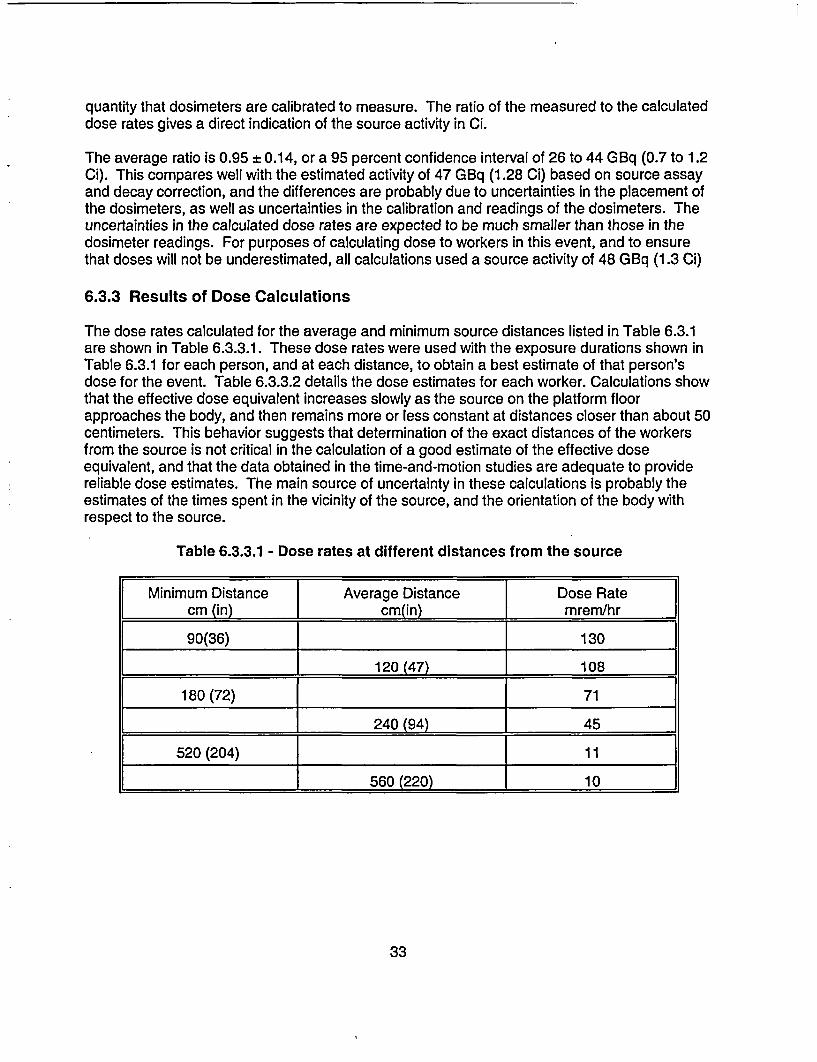
quantity that dosimeters are calibrated to measure. The ratio of the measured to the calculateddose rates gives a direct indication of the source activity in Ci.
The average ratio is 0.95 ± 0.14, or a 95 percent confidence interval of 26 to 44 GBq (0.7 to 1.2Ci). This compares well with the estimated activity of 47 GBq (1.28 Ci) based on source assayand decay correction, and the differences are probably due to uncertainties in the placement ofthe dosimeters, as well as uncertainties in the calibration and readings of the dosimeters. Theuncertainties in the calculated dose rates are expected to be much smaller than those in thedosimeter readings. For purposes of calculating dose to workers in this event, and to ensurethat doses will not be underestimated, all calculations used a source activity of 48 GBq (1.3 Ci)
6.3.3 Results of Dose Calculations
The dose rates calculated for the average and minimum source distances listed in Table 6.3.1are shown in Table 6.3.3.1. These dose rates were used with the exposure durations shown inTable 6.3.1 for each person, and at each distance, to obtain a best estimate of that person'sdose for the event. Table 6.3.3.2 details the dose estimates for each worker. Calculations showthat the effective dose equivalent increases slowly as the source on the platform floorapproaches the body, and then remains more or less constant at distances closer than about 50centimeters. This behavior suggests that determination of the exact distances of the workersfrom the source is not critical in the calculation of a good estimate of the effective doseequivalent, and that the data obtained in the time-and-motion studies are adequate to providereliable dose estimates. The main source of uncertainty in these calculations is probably theestimates of the times spent in the vicinity of the source, and the orientation of the body withrespect to the source.
Table 6.3.3.1 - Dose rates at different distances from the source
[Minimum Distance Average Distance Dose Rate[ cm (in) cm(in) mrem/hr
90(36) 130
l_ 120 (47) 108
180 (72) 71
l 240 (94) 1 45
520 (204) 11
_ 560 (220) 1 10
33
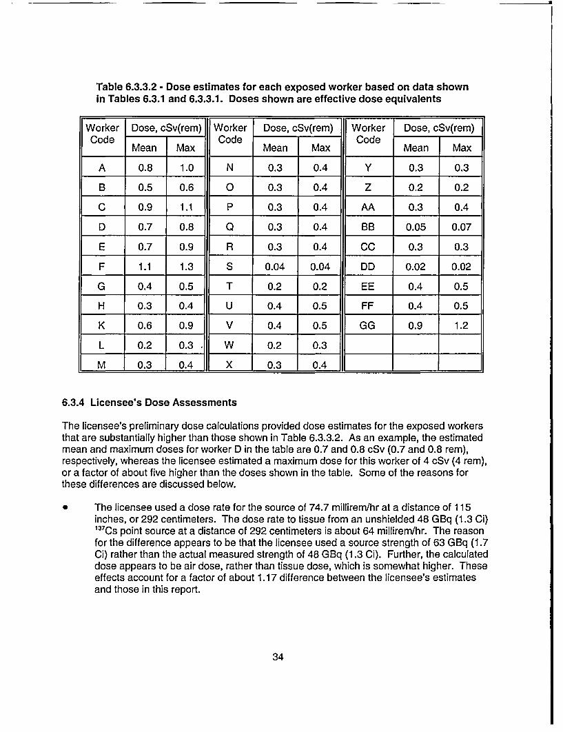
Table 6.3.3.2 - Dose estimates for each exposed worker based on data shownin Tables 6.3.1 and 6.3.3.1. Doses shown are effective dose equivalents
Worker Dose, cSv(rem) Worker Dose, cSv(rem) Worker Dose, cSv(rem)Code Code Code
Mean Max Mean Max Mean Max
A 0.8 1.0 N 0.3 0.4 Y 0.3 0.3
B 0.5 0.6 0 0.3 0.4 Z 0.2 0.2
C 0.9 1.1 P 0.3 0.4 AA 0.3 0.4
D 0.7 0.8 Q 0.3 0.4 BB 0.05 0.07
E 0.7 0.9 R 0.3 0.4 CC 0.3 0.3
F 1.1 1.3 S 0.04 0.04 DD 0.02 0.02
G 0.4 0.5 T 0.2 0.2 EE 0.4 0.5
H 0.3 0.4 U 0.4 0.5 FF 0.4 0.5
K 0.6 0.9 V 0.4 0.5 GG 0.9 1.2
L 0.2 0.3 * W 0.2 0.3
M 0.3 0.4 X 0.3 0.4
6.3.4 Licensee's Dose Assessments
The licensee's preliminary dose calculations provided dose estimates for the exposed workersthat are substantially higher than those shown in Table 6.3.3.2. As an example, the estimatedmean and maximum doses for worker D in the table are 0.7 and 0.8 cSv (0.7 and 0.8 rem),respectively, whereas the licensee estimated a maximum dose for this worker of 4 cSv (4 rem),or a factor of about five higher than the doses shown in the table. Some of the reasons forthese differences are discussed below.
* The licensee used a dose rate for the source of 74.7 millirem/hr at a distance of 115inches, or 292 centimeters. The dose rate to tissue from an unshielded 48 GBq (1.3 Ci)137 Cs point source at a distance of 292 centimeters is about 64 millirem/hr. The reasonfor the difference appears to be that the licensee used a source strength of 63 GBq (1.7Ci) rather than the actual measured strength of 48 GBq (1.3 Ci). Further, the calculateddose appears to be air dose, rather than tissue dose, which is somewhat higher. Theseeffects account for a factor of about 1.17 difference between the licensee's estimatesand those in this report.
34
* The licensee did not appear to account for any shielding, but the source was shielded bya minimum of 0.4 centimeter of steel, which reduces the dose rate from 64 millirem/hr toabout 51 millirem/hr. This accounts for an additional factor of about 1.25 difference.
* The licensee appears to have used the horizontal distance from the location of thesource on the floor to the location of the worker in the dose calculations. However, theclosest distance used in the calculations, which was 90 centimeters, is not representativeof the distance from the source to the worker's exposed organs and tissues. For aworker of an average height of 172 centimeters, the distance from the floor to mid-torsois about 100 centimeters. The distance from the source to that point, at a floor distancefrom the source of 90 centimeters, is 135 centimeters, and the dose rate at that distanceis a factor of about 2.25 times lower than at 90 centimeters.
* The licensee did not appear to have allowed for attenuation of the radiation in the tissuelayers overlying the exposed organs. Such attenuation would be significant because ofthe steep angle of incidence of the radiation from the floor up toward the body. Using anaverage overlying tissue layer thickness of 5 centimeters, the surface dose rate isreduced by a factor of about 1.6.
Accounting for all of the above factors reduces the dose rates estimated by the licensee by anoverall factor of about five, and results in closer agreement with the dose estimates shown inTable 6.3.3.2 above. The Monte Carlo calculations used in this report, based on MCNP,accurately take all of these factors into account as an integral part of the method.
Based on the above considerations, the doses in Table 6.3.3.2 will be considered to be the mostaccurate and reliable estimates based on physical evidence and event reconstruction. They are,however, conservative for reasons discussed in Section 6.3.5.
6.3.5 Conservatism in Dose Estimates
The dose estimates in Table 6.3.3.2 are probably upper limits on the doses likely received by theexposed workers. The conservatism in these dose estimates arises from two assumptions usedin the calculations, as discussed below.
* The calculations assumed that the lightly shielded front end of the source assemblyfaced the workers at all times during the exposure periods. However, the dose rate fromthe source assembly varies markedly depending on the side from which the exposure isreceived, because the radiation field from the source is highly directional. For example,the dose rate from the sides of the source assembly, that is, the sides normal to the longaxis of the assembly, is about 45 percent of the rate from the unshielded front side of theassembly, and is a factor of over 1000 lower when the assembly is viewed from the rear.This is due to the presence of a tungsten shield in the source assembly. Therefore, if itis assumed that the workers were exposed equally from all sides of the source during theexposure periods, the actual doses would be roughly 50 percent of the doses shown inTable 6.3.3.2.
* The calculations also assumed that the workers were exposed from the front side of thebody during the entire exposure period. However, the effective dose equivalent varies
35
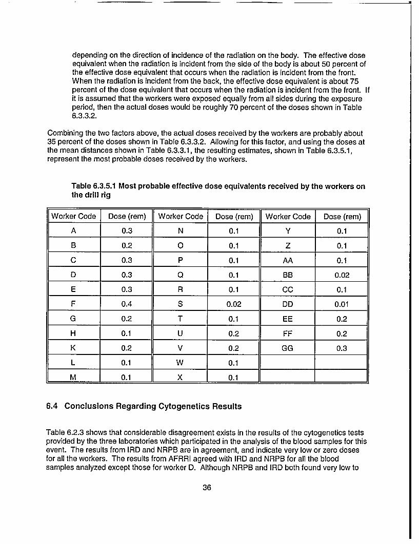
depending on the direction of incidence of the radiation on the body. The effective doseequivalent when the radiation is incident from the side of the body is about 50 percent ofthe effective dose equivalent that occurs when the radiation is incident from the front.When the radiation is incident from the back, the effective dose equivalent is about 75percent of the dose equivalent that occurs when the radiation is incident from the front. Ifit is assumed that the workers were exposed equally from all sides during the exposureperiod, then the actual doses would be roughly 70 percent of the doses shown in Table6.3.3.2.
Combining the two factors above, the actual doses received by the workers are probably about35 percent of the doses shown in Table 6.3.3.2. Allowing for this factor, and using the doses atthe mean distances shown in Table 6.3.3.1, the resulting estimates, shown in Table 6.3.5.1,represent the most probable doses received by the workers.
Table 6.3.5.1 Most probable effective dose equivalents received by the workers onthe drill rig
Worker Code Dose (rem) Worker Code Dose (rem) Worker Code Dose (rem)
A 0.3 N 0.1 Y 0.1
B 0.2 0 0.1 Z 0.1
C 0.3 P 0.1 AA 0.1
D 0.3 Q 0.1 BB 0.02
E 0.3 R 0.1 CC 0.1
F 0.4 S 0.02 DD 0.01
G 0.2 T 0.1 EE 0.2
H 0.1 U 0.2 FF 0.2
K 0.2 V 0.2 GG 0.3
L 0.1 W 0.1
M 0.1 X 0.1
6.4 Conclusions Regarding Cytogenetics Results
Table 6.2.3 shows that considerable disagreement exists in the results of the cytogenetics testsprovided by the three laboratories which participated in the analysis of the blood samples for thisevent. The results from IRD and NRPB are in agreement, and indicate very low or zero dosesfor all the workers. The results from AFRRI agreed with IRD and NRPB for all the bloodsamples analyzed except those for worker D. Although NRPB and IRD both found very low to
36
zero doses for this worker, AFRRI found a dose of 200 cGy (200 rads) for the first sample, anddid not formally report a dose for the second sample. Discussions between NRC and thelaboratories involved, as well as discussions between AFRRI and NRPB, indicated that thecause of the disagreements may be an unusual characteristic in worker D's chromosomes. Itappears that this characteristic causes some of worker D's chromosomes to show constrictionsthat, under the microscope, look like dicentrics. In addition, the arms of some of thechromosomes were crossed, again giving the impression of a dicentric when in fact none waspresent. Counting such constrictions and cross-overs as dicentrics would lead to erroneouslyhigh dose estimates.
Discussions were held between AFRRI and NRPB in an attempt to resolve the differences, butthese discussions did not lead to agreement on the results. AFRRI's estimate still officiallystands at 200 cGy (200 rad) for the first sample, and the result for the second sample has notbeen formally reported.
In view of these disagreements, the AIT was faced with having to decide on which of the resultsto accept as being most likely to be indicative of the actual exposure received by worker D. TheAIT decided to accept the NRPB results for a number of reasons. In any dose assessmentsituation such as this one, it is essential to use all available information in arriving at the bestestimate of dose, and the information that is used must be internally consistent. In this case, theavailable information included (1) dose calculations based on physical evidence, such as time-and-motion studies and knowledge of source activity, (2) clinical data during the period followingthe incident, (3) blood count data spanning the period between one week after the incident forseveral months subsequent to the incident, (4) reviews of the worker's clinical history, and (5)the results of the cytogenetics tests for the other six workers exposed in that incident whichshowed negative results. The exposure circumstances for these six workers, as determined frominterviews, did not differ significantly from those for worker D. All these sources of informationare consistent with a dose of the order of a centigray or less. In addition, because of therelatively low activity of the source involved, it is hard to devise a reasonable exposure scenariothat would produce doses approaching the tens of centigray level, much less hundreds ofcentigray. Therefore, none of the known sources of information relating to this case isconsistent with the AFRRI results.
37
7 AVAILABILITY AND TIMELINESS OF CYTOGENETIC TESTING
7.1 Process and Procedures
Cytogenetic testing to estimate radiation dose is based on the fact that ionizing radiation inducescharacteristic defects in the body's chromosomes, and these defects can be observed under themicroscope. Several types of chromosome defects, technically called aberrations, may be usedin such tests. The type used in this case, called the dicentric, is currently the most frequentlyused and the most reliable. For a number of reasons, the cells that are most suitable for use insuch tests are circulating lymphocytes. Lymphocytes are normally not cycling, that is, they arenot involved in active cell division. However, the best phase of the cell cycle to observe thechromosomes is during the metaphase part of active cell division, or mitosis. Therefore, toconduct a cytogenetics test, the exposed person's blood is drawn and special substances areadded to the blood samples that induce the lymphocytes to enter active cell division. The cellsare then left to incubate under strictly controlled conditions for about 48 hours, at which timemany of the cells will be in metaphase. At that point, the active cycle is halted by the addition ofother chemicals, and the cells are placed on glass microscope slides for examination.
The first stage of the microscopic examination is to identify the cells that were halted inmetaphase. The locations of these cells on the slide are then accurately recorded for laterexamination. After identifying a sufficient number of metaphases, normally 200 to 1000depending on the desired accuracy and sensitivity, the metaphases are examined carefully toidentify any dicentrics that may be present. The average number of dicentrics per cell is thencalculated. The photograph in Figure 7.1 shows a microscopic view of cells in metaphase, withthe chromosomes clearly visible. Four, or possibly five, dicentrics are seen in this slide. Thedicentrics are characterized by having two constrictions, rather than one normally seen inchromosomes at this stage of the cell cycle. The constriction actually represents a joining pointof a chromosome pair, called the centromere: hence the name dicentric for chromosomes withtwo centromeres.
The last phase of the test is to convert the average number of dicentrics per cell into a dose.Extensive research has demonstrated that the number of dicentrics per cell is proportional to thedose, though this proportionality is not linear but usually has the form of a quadratic function.The proportionality also varies with the type of radiation to which the person was exposed, forexample gamma rays, x rays, or neutrons, and it also varies with the dose rate. Therefore, eachlaboratory that performs cytogenetic testing usually develops a set of calibration curves, one foreach type of radiation and for different dose rate ranges. The average number of dicentrics percell is then used to enter these curves and read the dose. To do this correctly, it is necessary toknow the type of radiation to which the person was exposed and the approximate dose rate.This type of information is normally easily obtained from knowledge of the incident that led to theradiation exposure.
Because of statistical uncertainties in estimating the number of dicentrics per cell, the doseestimates obtained using this method are reported as a mean dose and a 95 percent confidenceinterval. For example, the results of the first test for worker D were reported as 148 to 249 cGy(148 to 249 rad), which is the 95 percent confidence interval, with a mean dose of 199 cGy (199rad). The size of the confidence interval can be reduced by examining a larger number of cells,but this process is limited because such examination is very time consuming. Much of the
38
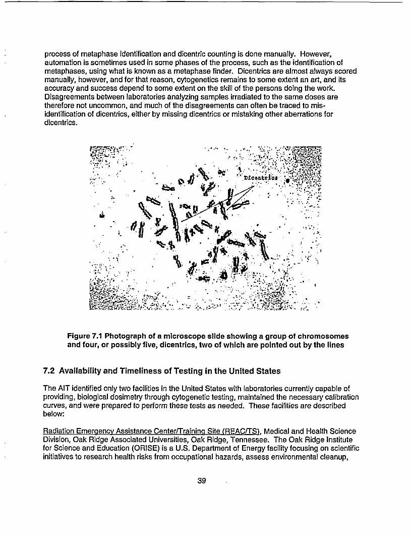
process of metaphase identification and dicentric counting is done manually. However,automation is sometimes used in some phases of the process, such as the identification ofmetaphases, using what is known as a metaphase finder. Dicentrics are almost always scoredmanually, however, and for that reason, cytogenetics remains to some extent an art, and itsaccuracy and success depend to some extent on the skill of the persons doing the work.Disagreements between laboratories analyzing samples irradiated to the same doses aretherefore not uncommon, and much of the disagreements can often be traced to mis-identification of dicentrics, either by missing dicentrics or mistaking other aberrations fordicentrics.
i'T. * , ~ ,.' *s,- .
in- - .;e! ft *a , .,,,
in 1*A i, ,-;; '''-' e -
Figure 7.1 Photograph of a microscope slide showing a group of chromosomesand four, or possibly five, dicentrics, two of which are pointed out by the lines
7.2 Availability and Timeliness of Testing in the United States
The AIT identified only two facilities in the United States with laboratories currently capable ofproviding, biological dosimetry through cytogenetic testing, maintained the necessary calibrationcurves, and were prepared to perform these tests as needed. These facilities are describedbelow:
Radiation Emergency Assistance Center/Training Site (REAC/TS), Medical and Health ScienceDivision, Oak Ridge Associated Universities, Oak Ridge, Tennessee. The Oak Ridge Institutefor Science and Education (ORISE) is a U.S. Department of Energy facility focusing on scientificinitiatives to research health risks from occupational hazards, assess environmental cleanup,
39
- J3
respond to radiation emergencies, support national security and emergency preparedness, andeducate the next generation of scientists. However, approximately 5 years ago, DOE ceasedfunding to support ORAU's cytogenetic biodosimetry program when interest shifted tolymphocyte proliferation testing for beryllium disease. NRC also subsequently eliminated itsfunding provided to REAC/TS for cytogenetic testing. Since that time, key personnel from theformer cytogenetics staff have left the institution and are retained as consultants on an as-needed basis.
The Armed Forces Radiobiologv Research Institute (AFRRI) was established in 1961, and is thesole Department of Defense research laboratory for medical radiological defense. Located inBethesda, Maryland, AFRRI's primary mission is to develop medical countermeasures againstionizing radiation. In addition to its core objective of developing, testing, and validatingdeployable biodosimetry systems for military field operations, AFRRI maintains one of thenation's few reference testing facilities for radiation dose assessment. At the time of thisinspection, although cytogenetic testing for civilian (non-military) accidents was outside ofAFRRI's mission, the institute has provided this support on a limited, case-by-case basis, sincethe time that REAC/TS lost its funding.
Although several clinical laboratories throughout the United States provide cytogenetic testingservices, these facilities analyze blood samples for chromosome abnormalities from the point ofview of pathological conditions, such as cancer and genetic disorders. Therefore, theselaboratories are not set up to perform testing for the detection of radiation induced chromosomedamage. These facilities have not established the necessary calibration curves required toestimate radiation dose to an exposed individual, and lack the staffing of experienced radiationcytogeneticists.
In the past, requests for biological dosimetry have been relatively few and somewhat sporadic.As a result, many government agencies have not found sufficient justification to provide long-term funding to support laboratories whose services were needed on an intermittent basis. Forthese reasons, only a limited number of expert biodosimetry laboratories are currently inexistence worldwide.
The current state of radiation cytogenetics testing in the United States, for use in doseassessments in unplanned acute exposures, needs improvement to assure the availability ofcytogenetic testing whenever it is needed in accidental radiation exposure situations. The onlyfacility that is now available to NRC for such testing within the United States on an ongoing andon-demand basis is AFRRI. This facility has been of assistance in the past, and may be able toassist in the future. However, AFRRI is organized and staffed as a research and armed forcessupport facility, and not for handling larger numbers of samples for cytogenetics testing. Casesinvolved more than a small number of samples probably cannot be handled to provide resultsrapidly enough, and in such cases it may be necessary to resort once more to overseaslaboratories.
40
8 REGULATORY OVERSIGHT FOR WELL LOGGING LICENSEES
8.1 Regulatory Requirements
On July 14, 1987, the NRC issued a final rule amending its regulations and license requirementsfor the use of radioactive material in well logging. The regulation, set out in a new Part 39,consolidated radiation safety requirements for well logging into one part, established specificradiation safety requirements, and promoted the adoption of uniform radiation safetyrequirements among NRC and Agreement States.
The purpose of establishing a new Part 39 specifically for well logging was to have in one placein the regulations the basic safety requirements for well logging. Formerly, the requirementswere often very general because they applied to many different types of licenses. The new Part39 established specific requirements for well logging that supplemented more generalrequirements contained in other parts (for example, training requirements in Part 19 or surveyrequirements in Part 20). The Statements of Consideration for the rule note that the rule wasdesigned to include safety requirements needed to reduce the likelihood of accidents involvingthe rupture of radioactive sources and the spread of radioactive contamination. Between 1982and 1986, five accidents occurred as a result of improperly removing a stuck source from a welllogging device or retrieving a well logging device lodged in a well.
Part 39.67 of Title 10 of the Code of Federal Regulations, "Radiation Surveys," requires, in part,that licensees (1) perform radiation surveys of the position occupied by each individual in thevehicle and the exterior of the vehicle used to transport the licensed material, (2) confirm that thelogging tool is free from contamination by energizing the logging tool or by using a survey meter,and (3) make a radiation survey at the temporary job site before and after each subsurfacetracer study to confirm the absence of contamination.
With the exception of the requirement to survey the position occupied by each individual in thevehicle, the survey requirements contained in Part 39 are aimed at reducing the spread ofcontamination. There is, however, no specific requirement in Part 39 for the licensee to surveythe rig floor and source storage containers prior to leaving the temporary job site. Requirementsfor the conduct of surveys are, however, stated in general terms in Part 20.
Part 20.1501 of Title 10 of the Code of Federal Regulations requires, in part, that each licenseeshall make or cause to be made, surveys that (1) may be necessary for the licensee to complywith the regulations in 10 CFR Part 20, and (2) are reasonable under the circumstances toevaluate (i) the magnitude and extent of radiation levels; (ii) concentrations or quantities ofradioactive material; and (iii) the potential radiological hazards. Survey means an evaluation ofthe radiological conditions and potential hazards incident to the production, use, transfer,release, disposal, or presence of radioactive material, or other source of radiation.
Although 10 CFR 20.1501 requires that licensees perform adequate surveys to ensurecompliance with the Standards for Protection Against Radiation, the team believes that a morespecific requirement should be contained within 10 CFR Part 39 to require a radiation survey ofthe rig floor and source containers prior to leaving the site. This is consistent with the specificityof Part 39 for the specific radiological hazards of logging operations, and would also mirrorsimilar radiation survey requirements contained in 10 CFR Part 34 (Industrial Radiography),
41

which are aimed at providing confirmation that sealed sources have been properly return to theirshielded containers at the completion of each radiographic exposure.
It should be noted that, although Part 39 does not require the surveys recommended by the AIT,STC did in fact have operating procedures in place that instruct the logging crew to performsimilar radiation surveys. However, the logging crew failed to perform these surveys. As notedin Section 5 of this report, the AIT identified the failure to perform a radiation survey of thesource storage container to verify that the logging source was in the properly shielded positionas a contributing cause of the event.
The team also considered the need for NRC to develop a regulatory requirement for loggingpersonnel who handle radiation sources to wear a chirper at all times during source handlingoperations. These are small radiation detectors that can be worn by individuals who may handleradiation sources, and provide audible signals indicating that a source of radiation is present.Chirpers and similar instruments that provide audible radiation alarms have been used by otherlicensees, such as radiographers, for similar purposes. The intent here is to provide well loggingpersonnel in the field with an additional warning to indicate that a radioactive logging source is inan unshielded configuration and/or that logging personnel have failed to properly perform aradiation survey to confirm that the source has been returned to its shielded container. Theteam believes that the use of a radiation detection device with an audible indication that sourcesare unshielded may prevent an overexposure incident due to the failure of logging personnel toproperly ensure the safe storage of these sources prior to leaving the well site.
Through discussions of this issue with several well logging licensees, as well as the States ofLouisiana, Oklahoma, and Texas, the team determined that a more reasonable and costeffective approach to this issue is to consider the implementation of a requirement that a surveymeter be physically present, with the audio feature engaged, in the immediate area wheresource handling is performed (rig floor, cat-walk, logging truck) at all times when sources areloaded and unloaded from the logging tools and source containers. Part 39 licensees arealready required to possess operable survey instruments and to calibrate these instruments atintervals not to exceed 6 months; therefore, this requirement will present no added cost for mostlicensees. There may, however, be some well logging licensees who currently possess a surveyinstrument without an audio feature.
8.2 Licensing Program
Persons authorized by the NRC to perform well logging operations using byproduct material arelicensed in accordance with the regulations in 10 CFR Part 30, "Rules of General Applicability toDomestic Licensing of Byproduct Material," and 10 CFR Part 39, "Licenses and Radiation SafetyRequirements for Well Logging."
Persons authorized by an Agreement State to use byproduct material in well logging operationsare licensed in accordance with corresponding statutory and administrative requirements inplace in that particular State.
In addition to the regulations, the NRC has provided well logging licensees and applicantssupplemental information published in NUREG 1556, Volume 14, "Program-Specific GuidanceAbout Well Logging, Tracer, and Field Flood Study Licenses." This guide contains a compilation
42
of information that an applicant would need to submit to be abl6 to receive an NRC licenseauthorizing well logging operations. The NRC staff reviews well logging license applicationsusing, in part, the criteria published in that document.
The team found that the licensing guidance, as written, is adequate based on the currentregulations. However, the guidance may need to be revised if the NRC promulgates thesuggested changes to Part 39.
8.3 Inspection Program
The NRC and the Agreement States perform routine inspections of well logging licensees todetermine if activities are performed in a manner that will protect the health and safety ofworkers and the general public and to determine if licensed programs are conducted inaccordance with applicable regulatory requirements and license conditions.
NRC Inspection Manual Chapter (IMC) 2800 describes the requirements for the inspection ofmost of NRC's materials licenses, including well logging activities. On April 15th, 2002, NRC'sOffice of Nuclear Material Safety and Safeguards (NMSS) implemented Temporary Instruction2800/033 (TI), issued to reflect a more performance-based approach to inspection activities.The TI specifies that an inspector's evaluation of a licensee's program will be based on directobservation of work activities, interviews with workers, demonstrations by workers performingtasks regulated by NRC, and independent measurements of radiological conditions at thefacility, rather than reliance on a review of records. The TI also changed the normal inspectionfrequency for well logging licensees from 3 to 5 years. Revision 1 of the TI, issued onOctober 21st , 2002, specified a reduction of the inspection interval to 1 year for well logginglicensees if the current inspection was limited to an office inspection and no temporary job siteinspection was completed. Yet another revision to the IMC (Revision 2) was issued onDecember 31 a, 2002. This latest version of the TI specifies an inspection interval of 3 years(rather than 1 year as described in Revision 1) for well logging licensees if the most currentinspection was limited to an office inspection and no temporary job site inspection wascompleted. In summary, as of December 315?, 2002, if a single inspection of a well logginglicensee is conducted at a temporary job site location, the normal inspection interval for thatlicensee is to be changed to a 5 year frequency for inspection.
Although the TI is a 'temporary instruction" aimed at collecting information to determine theappropriate course of action for the inspection program, the AIT believes that commenting onthe TI is within the scope of the team's charter. Based on the expectations presented in IMC2800, inspections are to be more performance-based in nature and are to be focused onobservations of work activities. From a strictly urisk-informed"l perspective, one can make theargument that 5 years, or even greater, may be acceptable. However, the team believes thatdirect observations of licensed activities conducted in the field by NRC inspectors is a significantindicator of licensee performance and should be conducted more often than once every fiveyears. For this reason, the team believes that a 5-year inspection frequency for observing welllogging activities is inconsistent with this "performance-based" philosophy, and should bereconsidered.
Through a review of records, and by interviews with several well logging licensees, it appearsthat NRC inspections rarely include the observation of licensed activities conducted at temporary
43
�i
job site locations. This is likely true for Agreement States as well. Some of the reasons for thedifficulty in conducting field site inspections of these licensees are that the job sites are oftenlocated in very remote areas, and the logging crews are not dispatched to the site until the wellreaches a specified depth, or the logging crew is on a short call-out schedule, which is oftendifficult to predict. This makes unannounced inspections very difficult. However, asdemonstrated by team members during this inspection, "announced" inspections can beaccomplished with a reasonable amount of effort, and the observations of activities in progressis worth the effort. The team encourages regional inspectors to increase their efforts to observewell logging activities in the field, even if the inspection must be announced to coordinate thiseffort.
It is also important to note that IMC 1220, "Processing of NRC Form 241, Report of ProposedActivities in Non-Agreement States, Areas of Exclusive Federal Jurisdiction, and OffshoreWaters, and Inspection of Agreement State Licensees Operating Under 10 CFR 150.20," wasrevised on June 6 , 2002, and now only requires that inspections be performed for licenseeswith inspection priorities 1, 2, or 3. The changes imposed by TI 2800/033 (inspection priority forwell logging was extended from 3 to 5 years), effectively eliminates the requirement for theregional offices to perform inspections of Agreement State licensees performing well loggingactivities in NRC jurisdiction. This is of concern because a significant amount of effort wasexpended by NRC to implement a Letter of Agreement with the U.S. Department of the Interior,Minerals Management Service, to provide NRC inspectors with helicopter transportation totemporary job sites in offshore waters, thereby allowing the agency to perform observations ofwell logging activities at several well site locations on an unannounced basis. The team believesthat this will significantly impact NRC's initiative of increasing the agency's inspection effort attemporary job site locations in offshore Federal waters in the Gulf of Mexico. This may alsohave a negative impact on public confidence with regard to the regulatory oversight of licensedactivities being conducted in offshore waters. Second only to industrial radiography licensees,the well logging community makes up a significant portion of licensed activities being performedin the Gulf of Mexico.
The NRC's specific procedure for performing inspections of well logging licensees are describedin Inspection Procedure (IP) 87113. Section 03.06 of IP 87113, "Equipment andInstrumentation," provides guidance to the inspector, instructing the inspector to verify that thelicensee has an inspection and maintenance program that provides for the visual check ofsource holders, logging tools, and source handling tools before each use. Additionally, theprocedure states that the licensee should have an established program for the semiannual visualinspection and maintenance of source holders, handling tools, etc., to ensure that no physicaldamage is visible and that the required labeling is visible.
Although the inspection procedure is designed to provide the inspector with "basic guidance",the team believes that IP 87113 should be modified to provide more specific instructionsregarding the minimum expectations for an inspector when reviewing a licensee's maintenanceand inspection program for safety-related equipment. The team believes that inspectors shouldrandomly examine, by visual inspection and through demonstrations by the licensee, sourcehandling tools and source containers, to verify that the equipment functions as designed. Thisshould be clearly articulated in the inspection procedure and/or through periodic trainingprovided to materials inspectors.
44
The team's review of IP 87123, issued on December 31W, 2002, as a revised version of IP87113, disclosed a similar concern. This revised procedure also does not provide instructionsregarding the minimum expectations for an inspector when reviewing a licensee's maintenanceand inspection program for safety-related equipment.
45
9 CONCLUSIONS
9.1 Conclusions
(a) The team determined that well logging sources do periodically fall off the handling toolsduring source transfers. However, these incidents are infrequent and when they dooccur, the logging crews usually immediately realize that the source has becomedetached and recovery of the source is accomplished quickly. Although the number ofthese incidents is quite small in comparison to the total number of successful sourcetransfers accomplished each day by well logging licensees, the team discovered severalinstances, similar to the May 2002 event, where STC logging personnel failed to noticethat sources were improperly transferred to their shielded containers, and as a resultmembers of the public were unintentionally exposed to radiation.
(b) The direct cause of the loss of control for this event was the failure to properly transferthe '3 7Cs sealed source to its storage container.
(c) Contributing and root causes of the event included (1) failure of the source storagecontainer plug to operate correctly, which may have provided a false indication that thesource was properly inserted, (2) failure to include a design specification for the retainingcable attached to the plug insert assembly for the source storage container, and failure toperform an adequate equipment failure analysis of the plug insert assembly, (3) failure toperform a radiation survey of the source storage container to verify that the loggingsource was in the properly shielded position, as well as failure to perform a radiationsurvey of the logging tool immediately following removal of the sealed sources, and (4)failure to adequately investigate precursor events to determine root causes, focusingprimarily on the direct causes of events and not on factors whose existence maderecurrent events more probable.
(d) Although the team agrees with the licensee that a radiation survey of the sourcecontainer would have likely prevented the exposures to members of the public, it appearsthat STC's investigation did not focus sufficient attention on why the source, in this andprevious similar events, continued to fall off the handling tool, and why logging engineerscontinued to fail to conduct radiation surveys and follow other standard operatingprocedures.
(e) The team determined that all of the exposed individuals were correctly identified by STCand that the licensee's dose estimates for these workers were reasonable based on theinformation available at the time of the licensee's investigation. As described in Section 6of this report, the team concluded that STC's dose estimates were very conservative andwell in excess of the doses calculated by the AIT. Nevertheless, through interviews withthe exposed individuals, and the worker's management representatives, the teamdetermined that STC failed to provide any followup information regarding estimateddoses or a summary of its investigation result the exposed workers, even though this isrequired by NRC regulation. This lack of information created anxiety in several workerswho were concerned about potential health effects resulting from their radiationexposure.
46
(f) The NRC does not currently review or approve the design or performance standards forwell logging source handling tools used by licensees to transfer sealed sources to andfrom their shielded containers to be loaded and unloaded into well logging tools usedduring logging operations. However, the team did not identify any specific generic issuesor safety concerns with the design of the equipment used during logging operations.
(g) During the course of this inspection, it became apparent to the team that numerousdifferent designs of handling tools currently exist within the industry, and imposing astandard design would be unnecessary and impractical. This notwithstanding, in light ofthe number of source handling incidents, and based on interviews with severalindividuals, the team believes that the well logging industry should consider a furtherevaluation of this issue to determine if minimum engineering design and/or performancestandards should be developed, similar in nature to the industry standards for associatedsafety equipment used in industrial radiography.
(h) Biological dosimetry performed on some of the workers indicated doses that were belowthe thresholds for these methods, therefore yielding dose estimates that are below about10 to 20 cGy (10 to 20 rad). This is generally the threshold of reliable dose estimates forthe most sensitive of these methods, cytogenetic testing. These results are consistentwith the dose estimates based on time-and-motion studies.
(i) Dose estimates based on time-and-motion studies show that the doses received by anyof the workers are in the range of 0 to 1 cGy (0 to 1 rad). Most of the doses areestimated to be at or slightly above NRC's dose limit for members of the public of 0.1 cSv(0.1 rem) per year, but far below NRC's dose limit for occupational exposures, which is 5cSv (5 rem) per year.
U) The estimated doses are all well below the level at which clinically observable, short-termhealth effects would be expected. In this case, short-term here is used to mean withindays to weeks of the radiation exposure.
(k) The expected long-term effect is a slight increase in the probability of developing cancer,and possibly no effect. No direct evidence currently exists that cancer risk increases asa result of radiation exposure to doses below about 10 cGy (10 rad). However, thecurrent approach to regulation of radiation exposure is to assume that such a risk doesexist at any dose level, and that the risk increases in proportion to the dose received.The currently used risk coefficient at low doses is very small, about in 2000 per cGy ofwhole body dose. The cancer risk due to natural causes is about 1 in 5.
(I) The current state of radiation cytogenetics testing in the United States, for use in doseassessments in unplanned acute exposures, urgently needs to be improved, and theappropriate Federal agencies must work collaboratively to provide a long-term solution,as well as to address the immediate need for such services.
47
APPENDIX A
AUGMENTED INSPECTION TEAM CHARTER
UNITED STATESNUCLEAR REGULATORY COMMISSION
REGION IV611 RYAN PLAZA DRIVE, SUITE 400
ARLINGTON, TEXAS 76011-8064
September 25, 2002
MEMORANDUM TO: Mark R. Shaffer, ChiefNuclear Materials Inspection Branch
FROM: Ellis W. Merschoff /RAIRegional Administrator
SUBJECT: REVISED CHARTER FOR THE AUGMENTED INSPECTIONTEAM FOR THE SCHLUMBERGER TECHNOLOGYCORPORATION OVER-EXPOSURE EVENT (CHANGES NOTEDIN BOLD)
In response to recently obtained cytogenetic testing information completed for an individualexposed to radiation due to the loss of control of a Schlumberger Technology Corporationlogging source, the ongoing special inspection of this event is being upgraded to an AugmentedInspection Team (AIT). You are hereby designated as the AIT leader.
A. Basis
On May 23, 2002, Schlumberger Technology Corporation, a Region IV well logginglicensee, contacted the NRC Operations Center to report the loss of control of a sealedsource containing approximately 44 gigabequerels (1.2 curies) of cesium-137. Aspecial, reactive inspection was conducted on May 25-26, 2002, to examine the drill rig,witness interviews conducted by the licensee with some of the potentially exposedindividuals, and conduct independent interviews with licensee personnel.
In a written report from the licensee, received by NRC on June 26, 2002, SchlumbergerTechnology Corporation provided updated information regarding its investigation of theevent. At that time, the licensee believed it had bounded the exposures to members ofthe public (drill rig crew members), and calculated the highest exposure to an individualto be approximately 6.4 rems. As a precautionary measure, blood tests were performedon 10 individuals. In addition, cytogenetic testing was performed on one of theseindividuals. On August 30,2002, Region IV was provided with the results of thecytogenetic tests; the results indicate that the individual received a whole-bodyequivalent dose that is significantly higher than what the licensee had previouslycalculated. Consequently, the ongoing special inspection is being upgraded to an AIT.
A-1
Mark R. Shaffer
B. Scope
The AIT is to examine the circumstances surrounding the exposures to members of thegeneral public (oilgas drilling rig crew) as a result of the loss of control of a well loggingsource containing cesium-1 37. The scope of the AIT investigation should include, but isnot limited to the following:
1. Develop a detailed sequence of events associated with the loss of control of thelicensee's well logging source up to and including the results of a cytogenetic testfor one individual.
2. Determine potential root and contributing causes for the loss of control of the welllogging source including a review of any precursor events involving thelicensee, and any similar events or operating experience.
3. Review and evaluate the scope and thoroughness of the licensee's response toand investigation of the event including the completeness and accuracy ofreporting of the event.
4. Review and evaluate the licensee's dose estimate results to determine if licenseeinitial estimates were reasonable based on available information.
5. Perform independent dose estimates. Conduct interviews to determine the mostlikely dose scenarios.
6. Determine if all of the potentially exposed individuals have been identified by thelicensee.
7. Evaluate the availability and timeliness of the cytogenetic testing and understandthe basis for the results relative to their accuracy and validity, including anunderstanding of any possible factors that may have influenced thecytogenetic results.
8. Review results of any additional cytogenetic testing to be performed.
9. Identify potential generic issues.
10. Review the adequacy of the licensing and inspection program requirementsfor this type of licensee, including the need for changes.
11. Review the adequacy of regulatory requirements based on the risk associatedwith the control of well logging sources, to ensure safety and security.
A-2
C. Guidance
This memorandum designates you as the AIT leader. Your duties will be as describedin Inspection Procedure 93800, Augmented Inspection Team." The team compositionhas been discussed with you directly. During performance of the augmented inspection,designated team members are separated from their normal duties and report directly toyou. The team is to emphasize fact-finding in its review of the circumstancessurrounding the event, and it is not the responsibility of the team to examine theregulatory process. Safety concerns identified that are not directly related to the eventshould be reported to the Region IV office for appropriate action.
The team will conduct an entrance meeting with the licensee at the start of theinvestigation, and thereafter will immediately begin a review in accordance with thescope of this charter. An exit meeting should be completed following the completion ofthe inspection including a review of results of any further cytogenetic studies, asdeemed appropriate, with a report documenting the results of the inspection, includingfindings and conclusions, issued within 30 days of the exit briefing.
This Charter may be modified should the team develop significant new information thatwarrants review. Should you have any questions concerning this Charter, contactDwight D. Chamberlain at (817) 860-8106.
Distribution:M. J. Virgilio, NMSS/OD (MS 8A23)M. V. Federline, NMSS/OD (MS 8A23)D. A. Cool, NMSS/IMNS (MS 8F5)R. P. Zimmerman, NSIR/OD (MS 4 D18)E. W. MerschoffT. P. GwynnD. D. ChamberlainH. J. Miller, RIL. A. Reyes, RIIJ. E. Dyer, RIllR. D. Hannah, PAOW. A. Maier
A-3
APPENDIX B
SEQUENCE OF EVENTS
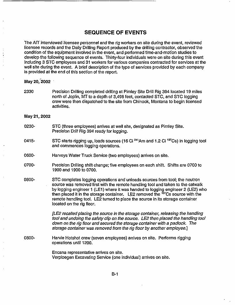
SEQUENCE OF EVENTS
The AIT interviewed licensee personnel and the rig workers on site during the event, reviewedlicensee records and the Daily Drilling Report produced by the drilling contractor, observed thecondition of the equipment involved in the event, and performed time-and-motion studies todevelop the following sequence of events. Thirty-four individuals were on site during this eventincluding 3 STC employees and 31 workers for various companies contracted for services at thewell site during the event. A brief description of the type of services provided by each companyis provided at the end of this section of the report.
May 20, 2002
2330 Precision Drilling completed drilling at Pimley Site Drill Rig 394 located 19 milesnorth of Joplin, MT to a depth of 3,498 feet, contacted STC, and STC loggingcrew were then dispatched to the site from Chinook, Montana to begin licensedactivities.
May 21, 2002
0230- STC (three employees) arrives at well site, designated as Pimley Site.Precision Drill Rig 394 ready for logging.
0415- STC starts rigging up, loads sources (16 Ci 24'Am and 1.2 Ci 1 3 7 CS) in logging tooland commences logging operations.
0600- Harveys Water Truck Service (two employees) arrives on site.
0700- Precision Drilling shift change; five employees on each shift. Shifts are 0700 to1900 and 1900 to 0700.
0800- STC completes logging operations and unloads sources from tool; the neutronsource was removed first with the remote handling tool and taken to the catwalkby logging engineer 1 (LE1) where it was handed to logging engineer 2 (LE2) whothen placed it in the storage container. LE2 removed the '37Cs source with theremote handling tool. LE2 turned to place the source in its storage containerlocated on the rig floor.
[LE2 recalled placing the source in the storage container, releasing the handlingtool and undoing the safety clip on the source. LE2 then placed the handling tooldown on the rig floor and secured the storage container with a padlock. Thestorage container was removed from the rig floor by another employee.]
0800- Harvie Hotshot crew (seven employees) arrives on site. Performs riggingoperations until 1200.
Encana representative arrives on site.Verploegen Excavating Service (one individual) arrives on site.
B-1
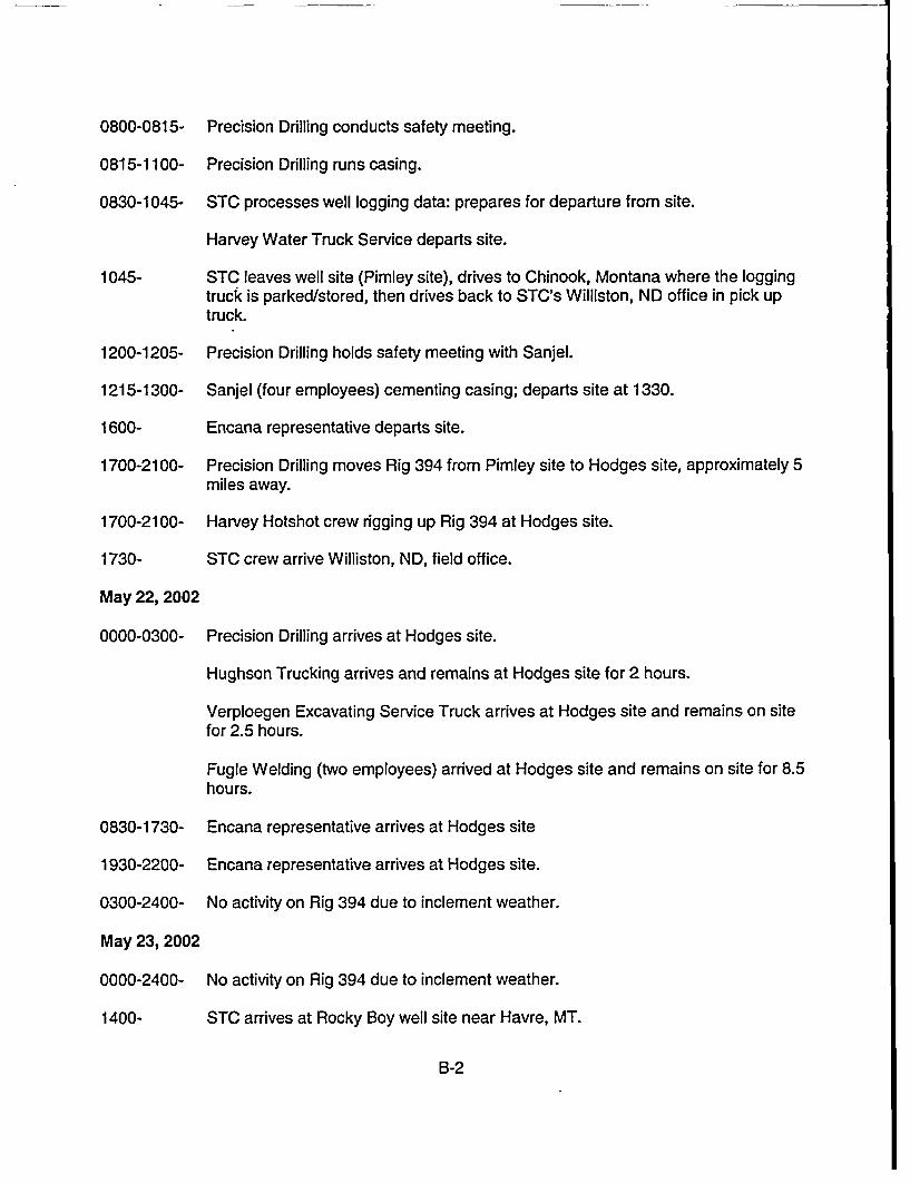
--
0800-0815-
0815-1100-
0830-1045-
1045-
1200-1205-
1215-1300-
1600-
1700-2100-
1700-2100-
1730-
May 22, 2002
0000-0300-
Precision Drilling conducts safety meeting.
Precision Drilling runs casing.
STC processes well logging data: prepares for departure from site.
Harvey Water Truck Service departs site.
STC leaves well site (Pimley site), drives to Chinook, Montana where the loggingtruck is parked/stored, then drives back to STC's Williston, ND office in pick uptruck.
Precision Drilling holds safety meeting with Sanjel.
Sanjel (four employees) cementing casing; departs site at 1330.
Encana representative departs site.
Precision Drilling moves Rig 394 from Pimley site to Hodges site, approximately 5miles away.
Harvey Hotshot crew rigging up Rig 394 at Hodges site.
STC crew arrive Williston, ND, field office.
Precision Drilling arrives at Hodges site.
Hughson Trucking arrives and remains at Hodges site for 2 hours.
Verploegen Excavating Service Truck arrives at Hodges site and remains on sitefor 2.5 hours.
Fugle Welding (two employees) arrived at Hodges site and remains on site for 8.5hours.
0830-1730-
1930-2200-
0300-2400-
May 23, 2002
0000-2400-
1400-
Encana representative arrives at Hodges site
Encana representative arrives at Hodges site.
No activity on Rig 394 due to inclement weather.
No activity on Rig 394 due to inclement weather.
STC arrives at Rocky Boy well site near Havre, MT.
B-2
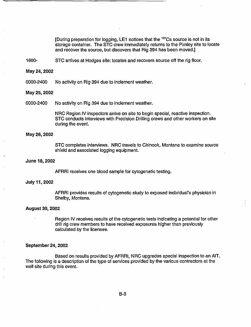
[During preparation for logging, LE1 notices that the '3 7 Cs source is not in itsstorage container. The STC crew immediately returns to the Pimley site to locateand recover the source, but discovers that Rig 394 has been moved.]
1600- STC arrives at Hodges site: locates and recovers source off the rig floor.
May 24, 2002
0000-2400 No activity on Rig 394 due to inclement weather.
May 25, 2002
0000-2400 No activity on Rig 394 due to inclement weather.
NRC Region IV inspectors arrive on site to begin special, reactive inspection.STC conducts interviews with Precision Drilling crews and other workers on siteduring the event.
May 26, 2002
STC completes interviews. NRC travels to Chinook, Montana to examine sourceshield and associated logging equipment.
June 18, 2002
AFRRI receives one blood sample for cytogenetic testing.
July 11, 2002
AFRRI provides results of cytogenetic study to exposed individual's physician inShelby, Montana.
August 30,2002
Region IV receives results of the cytogenetic tests indicating a potential for otherdrill rig crew members to have received exposures higher than previouslycalculated by the licensee.
September 24, 2002
Based on results provided by AFRRI, NRC upgrades special inspection to an AIT.The following is a description of the type of services provided by the various contractors at thewell site during this event.
B-3
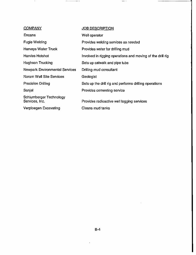
--
COMPANY
Encana
Fugle Welding
Harveys Water Truck
Harvies Hotshot
Hughson Trucking
Newpark Environmental Services
Noram Well Site Services
Precision Drilling
Sanjel
Schlumberger TechnologyServices, Inc.
Verploegen Excavating
JOB DESCRIPTION
Well operator
Provides welding services as needed
Provides water for drilling mud
Involved in rigging operations and moving of the drill rig
Sets up catwalk and pipe tubs
Drilling mud consultant
Geologist
Sets up the drill rig and performs drilling operations
Provides cementing service
Provides radioactive well logging services
Cleans mud tanks
B-4
APPENDIX C
GLOSSARY
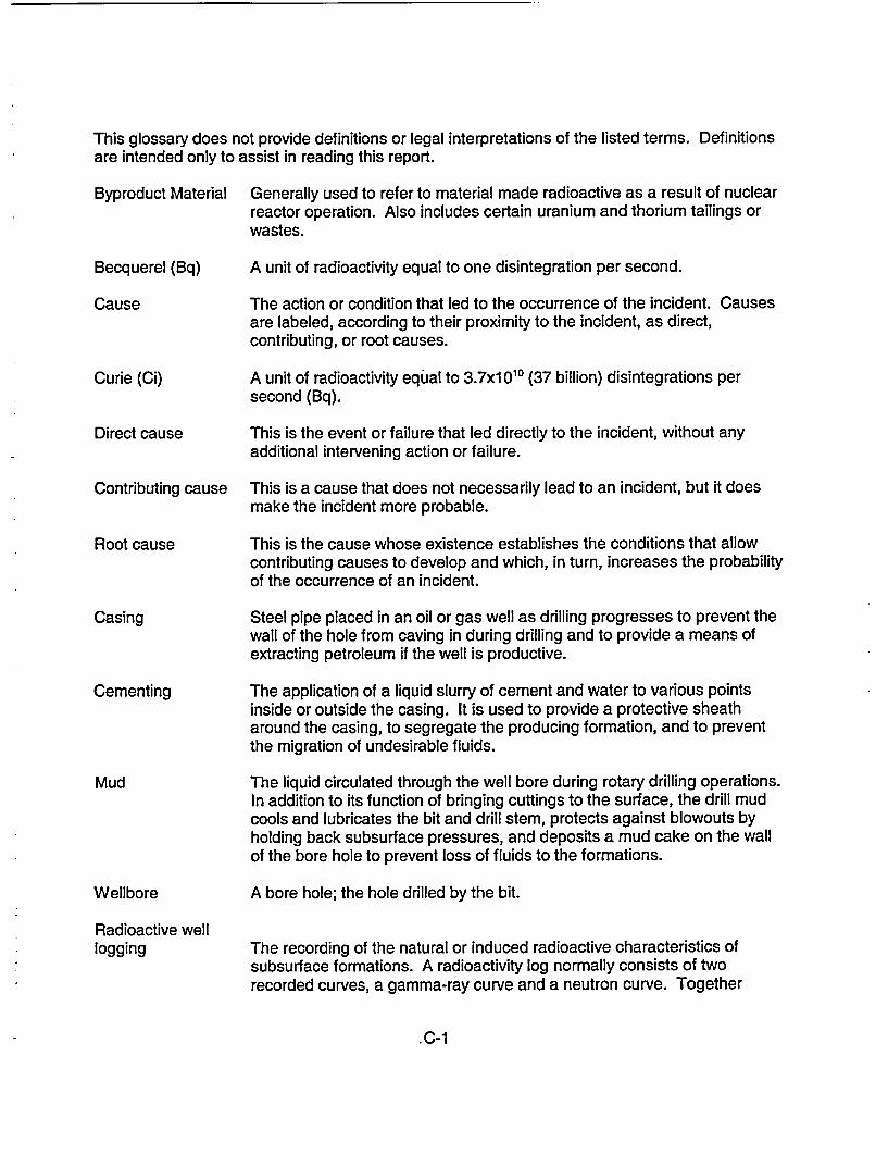
This glossary does not provide definitions or legal interpretations of the listed terms. Definitionsare intended only to assist in reading this report.
Byproduct Material
Becquerel (Bq)
Cause
Curie (Ci)
Direct cause
Contributing cause
Root cause
Casing
Cementing
Mud
Wellbore
Generally used to refer to material made radioactive as a result of nuclearreactor operation. Also includes certain uranium and thorium tailings orwastes.
A unit of radioactivity equal to one disintegration per second.
The action or condition that led to the occurrence of the incident. Causesare labeled, according to their proximity to the incident, as direct,contributing, or root causes.
A unit of radioactivity equjal to 3.7x1 0Q1 (37 billion) disintegrations persecond (Bq).
This is the event or failure that led directly to the incident, without anyadditional intervening action or failure.
This is a cause that does not necessarily lead to an incident, but it doesmake the incident more probable.
This is the cause whose existence establishes the conditions that allowcontributing causes to develop and which, in turn, increases the probabilityof the occurrence of an incident.
Steel pipe placed in an oil or gas well as drilling progresses to prevent thewall of the hole from caving in during drilling and to provide a means ofextracting petroleum if the well is productive.
The application of a liquid slurry of cement and water to various pointsinside or outside the casing. It is used to provide a protective sheatharound the casing, to segregate the producing formation, and to preventthe migration of undesirable fluids.
The liquid circulated through the well bore during rotary drilling operations.In addition to its function of bringing cuttings to the surface, the drill mudcools and lubricates the bit and drill stem, protects against blowouts byholding back subsurface pressures, and deposits a mud cake on the wallof the bore hole to prevent loss of fluids to the formations.
A bore hole; the hole drilled by the bit.
Radioactive welllogging The recording of the natural or induced radioactive characteristics of
subsurface formations. A radioactivity log normally consists of tworecorded curves, a gamma-ray curve and a neutron curve. Together
C-1
Trip
Tool pusher
Rig up
Rig down
these indicate the types of rocks in the formation and the types of fluidscontained in the rocks.
The operation of hoisting the drill stem from and returning it to the wellbore.
An employee of the drilling contractor who is in charge of the entire drillingcrew and the drilling rig.
To prepare the drilling rig for making a hole; to install tools and machinerybefore drilling is started.
To dismantle the drilling rig and auxiliary equipment following completionof drilling operations.
C-2
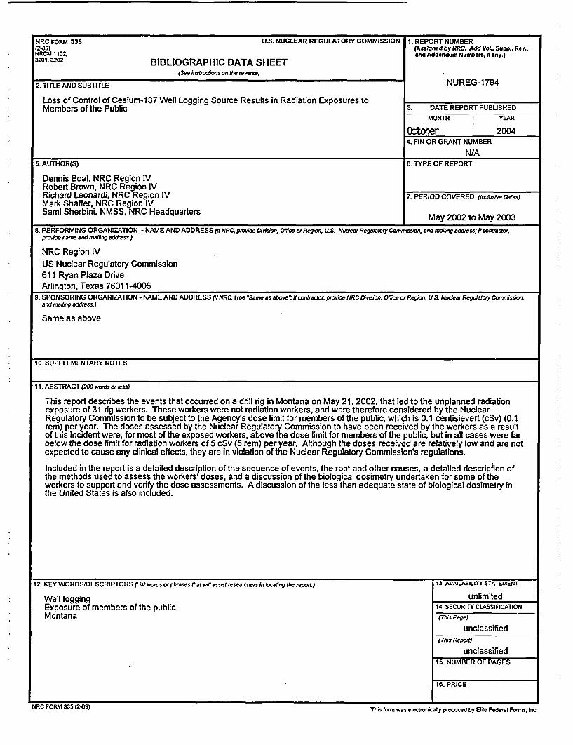
NRC FORM 335 U.S. NUCLEAR REGULATORY COMMISSION 1. REPORT NUMBER(289) (Assigned by NRC. Add Vol., Supp., Rev.,NRCM 1102. and Addendum Numbers, If any.)3201,3 BIBLIOGRAPHIC DATA SHEET
(See instuctions on the reverse)
2. TITLE AND SUBTITLE NUREG-1794
Loss of Control of Cesium-137 Well Logging Source Results in Radiation Exposures toMembers of the Public 3. DATE REPORT PUBUSHED
MONTH YEAR
Ocftoer 20044. FIN OR GRANT NUMBER
N/A5. AUTHOR(S) 6. TYPE OF REPORT
Dennis Boal, NRC Region IVRobert Brown, NRC Region IVRichard Leonardi, NRC Region IV 7. PERIOD COVERED (incdusive Dates)Mark Shaffer, NRC Region IVSami Sherbini, NMSS, NRC Headquarters May 2002 to May 2003
8. PERFORMING ORGANIZATION - NAME AND ADDRESS (IfNRC, provide Division., Ofice orRegion. U.S. NuudearRegulatory Commrission, aendmailing address; if contractor.provide arnae and maifing address.)
NRC Region IVUS Nuclear Regulatory Commission611 Ryan Plaza DriveArlington, Texas 76011-4005
9. SPONSORING ORGANIZATION - NAME AND ADDRESS (ffNRC, lype'Samne as above'; itrontractor, provide NtRC Division, Offce orRegio~n, U.S. NuclearRegurahry Commnission,and mailing address.)
Same as above
10. SUPPLEMENTARY NOTES
I11. ABSTRACT (200 words orless)
This report describes the events that occurred on a drill rig in Montana on May 21. 2002, that led to the unplanned radiationexposure of 31 rig workers. These workers were not radiation workers, and were therefore considered by the NuclearRegulatory Commission to be subject to the Agency's dose limit for members of the public, which is 0.1 centisievert (cSv) (0.1rem) per year. The doses assessed by the Nuclear Regulatory Commission to have been received by the workers as a resultof this incident were, for most of the exposed workers, above the dose limit for members of the public, but in all cases were farbelow the dose limit for radiation workers of 5 cSv (5 rem) per year. Although the doses received are relatively low and are notexpected to cause any clinical effects, they are in violation of the Nuclear Regulatory Commission's regulations.
Included in the report is a detailed description of the sequence of events, the root and other causes, a detailed description ofthe methods used to assess the workers' doses, and a discussion of the biological dosimetry undertaken for some of theworkers to support and verify the dose assessments. A discussion of the less than adequate state of biological dosimetry inthe United States is also included.
12. KEY WORDS/DESCRIPTORS (ist words orphrases that wiln assist researchers in locating the report.) 13. AVAILABILITY STATEMENT
Well logging unlimitedExposure of members of the public 14. SECURITY CLASSIFICATIONMontana (Mhs Page)
unclassified(This Report)
unclassified15. NUMBER OF PAGES
16. PRICE
NRC FORM 335 (2-B9) This form was electronically produced by Elite Federal Forms. Inc.
_ _ _ -J
Federal Recycling Program
NUREG-1794 LOSS OF CONTROL OF CESIUNI-137 WELL LOGGING SOURCE RESULTING INRADIATION EXPOSURES TO MEMBERS OF TIHE PUBLIC
OCTOBER 2004
UNITED STATESNUCLEAR REGULATORY COMMISSION
WASHINGTON, DC 20555-0001
OFFICIAL BUSINESS