Embed Size (px)
Citation preview

NURail Project ID: NURail2012-UTK-E01
Develop Railway Engineering Modules in UTK Civil Engineering Undergraduate and Graduate Courses
By
Baoshan Huang Edwin G. Burdette Professor
Department of Civil and Environmental Engineering The University of Tennessee, Knoxville
05-31-2015
Grant Number: DTRT12-G-UTC18

DISCLAIMER
Funding for this research was provided by the NURail Center, University of Illinois at Urbana - Champaign under Grant No. DTRT12-G-UTC18 of the U.S. Department of Transportation, Office of the Assistant Secretary for Research & Technology (OST-R), University Transportation Centers Program. The contents of this report reflect the views of the authors, who are responsible for the facts and the accuracy of the information presented herein. This document is disseminated under the sponsorship of the U.S. Department of Transportation’s University Transportation Centers Program, in the interest of information exchange. The U.S. Government assumes no liability for the contents or use thereof.
TECHNICAL SUMMARY
Title
Develop Railway Engineering Modules in UTK Civil Engineering Undergraduate and Graduate Courses
Introduction
The importance of railway transport has long been recognized. However, no railway engineering courses have been provided in the UTK civil engineering curricula. The objective of this education project is to develop some railway engineering modules based on the PI’s research and teaching experience for many years so that independent railway engineering courses or even programs can be established in the future.
The railroad material characterization modules, such as aggregate, railroad track steel, Portland cement concrete, railroad ties, and asphalt concrete for railroad applications, will be incorporated in the existing civil engineering courses the PI is currently teaching: CE321 – Construction Materials, CE522 - Asphalt and PCC Mix Design and CE525 - Pavement Materials Characterization. The railroad design modules will be incorporated in the PI’s pavement design course: CE521 – Pavement Design. More teaching modules will be developed based on the outcomes of the PI’s research.
Description of Activities
The PI developed two teaching modules for railway engineering in PowerPoint slides. The two modules have been partially or fully used in the PI’s teaching courses: CE321 – Construction Materials (every semester, undergraduate), CE522 - Asphalt and PCC Mix Design (Spring 2014, graduate), CE691 – Advanced Materials Characterization (Fall 2013, graduate), CE521 – Pavement Design (Summer 2013, Spring 2015, graduate).
Outcomes
Two railway engineering modules were developed. The first module is “Railroad Paving Materials” and it covers definitions of ballasted and ballastless tracks, types of ballastless tracks, slab track structure, emulsified asphalt cement mortar, and fastening system. The second module is “Railway Trackbeds” and its contents include materials properties, conventional designs, and innovative designs.
Conclusions/Recommendations
Two railway engineering modules were developed. More will be developed based on results and findings from the PI’s railroad research projects .

Publications/Examples
The two railway engineering modules developed in PowerPoint slides were attached. Primary Contact Principal Investigator Baoshan Huang Edwin G. Burdette Professor Department of Civil and Environmental Engineering The University of Tennessee, Knoxville (865)974-7713 [email protected] Other Faculty and Students Involved N/A NURail Center 217-244-4999 [email protected] http://www.nurailcenter.org/

R il d P i M t i lR il d P i M t i lRailroad Paving MaterialsRailroad Paving Materials(Ballastless)(Ballastless)
OutlinesOutlines Advantage and Disadvantages of Ballasted Track
Advantage and Disadvantages of Ballastless Track
Design Features in Ballastless Track
Types of Ballastless Track
Slab Track Structure
Emulsified Asphalt Cement Mortar (EACM)
Requirements and Properties
Fastening System

Ballasted TrackBallasted Track
Advantages R l ti l l t ti t Relatively low construction costs High elasticity High maintainability at relatively low cost High noise absorption
Ballasted TrackBallasted Track
Disadvantages Over time, the track tends to “float”, in both longitudinal and lateral directions, as a result of non-linear, irreversible behavior of the materials. Limited non-compensated lateral acceleration in curves, due to the limited lateral resistance offered by the ballast.

Ballasted TrackBallasted Track
Disadvantages B ll b h d hi h d i Ballast can be churned up at high speeds, causing serious damage to rails and wheels. Reduced permeability due to contamination, grinding-down of the ballast and transfer of fine particles from subgrade.
Ballasted TrackBallasted Track
Disadvantages B ll i l i l h l di i Ballast is relatively heavy, leading to an increase in the costs of building bridges and viaducts. Ballasted track is relatively high and has direct consequences for tunnel diameters and for access points.

Ballasted TrackBallasted Track
Other reasons for seeking alternative to ballasted ktrack
Lack of suitable ballast material Make track accessible to road vehicles Dust from the ballast into the environment
BallastlessBallastless Track Track -- HistoryHistory Early High-Speed rail built on ballast -- Tokaido Shinkansen from Tokyo to Shin-Osaka, completed in 1964; However, with the increase of traffic intensity, damage frequently occurred; The high-rate economic growth and reduction in working hours, labor shortage and limited interval time for track maintenance created the need to introduced a new low-maintenance track. In 1965, the former Japanese National Railways (JNR) started a study on slab tracks

BallastlessBallastless TrackTrack
Advantages d d h i h Reduced height Dust free Lower maintenance requirement and hence higher availability Increased service life lif l Lower life cycle-cost
BallastlessBallastless TrackTrack
Disadvantages Requires high precision laying by automated Requires high precision laying by automated machines Expert supervision Higher cost, about 1.5-2.0 times conventional ballasted track Derailments can cause costly damage Derailments can cause costly damage Repair work is more complicated Noise level increases

Design PrinciplesDesign Principles
Enough Strength and Stability
Reasonable design scheme of manufacturing, laying and fine-adjusting of track system
High safety
Good smoothness
Reasonable structure types and durable engineering material
Low maintenance
Loads on Slab TrackLoads on Slab Track
Dead load Structure weight Shrinkage and creep of concrete Live load Vertical force Lateral force Temperature force Flexure of bridgeFlexure of bridge Additional load Brake/traction force Uneven settlement of subgrade Special load (construction temporary force)

Dynamic Analysis of Train-Track-Foundation
Train-track-foundation dynamic model
Track ResilienceTrack Resilience
Ballasted tracks Ballast provides half of the resilience. Subgrade provides the other half.
Slab tracks (ballastless) Slab absorbs little dynamic forces. Limited capability of subgrade for dynamic force absorption Additional resilience needed

Two Ways to Add ResilienceTwo Ways to Add Resilience
Extra resilience under the rail with extra thick rail dpads.
A second resilient layer under supporting blocks or the sleepers.
Supporting layersSupporting layers
Ballastless tracks can be built on Asphalt supporting layer Concrete supporting layer
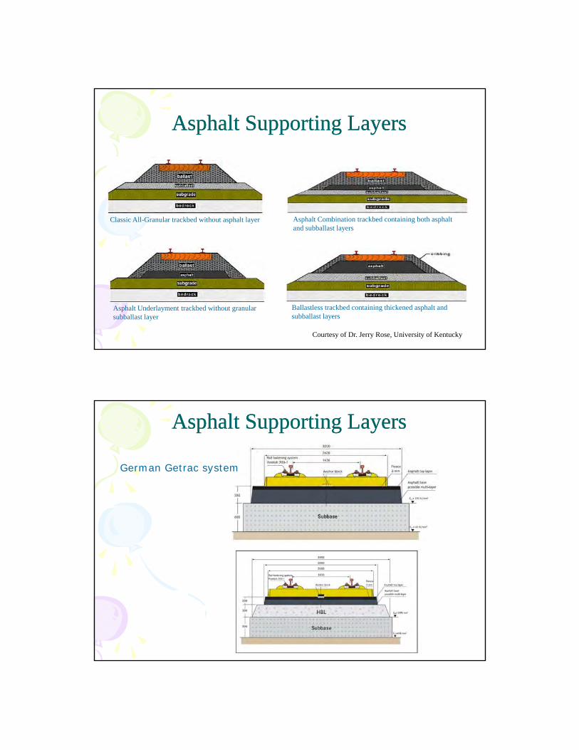
Asphalt Supporting LayersAsphalt Supporting Layers
Classic All-Granular trackbed without asphalt layer Asphalt Combination trackbed containing both asphalt and subballast layers
Asphalt Underlayment trackbed without granular subballast layer
Ballastless trackbed containing thickened asphalt and subballast layers
Courtesy of Dr. Jerry Rose, University of Kentucky
Asphalt Supporting LayersAsphalt Supporting Layers
German Getrac system

Concrete Supporting LayersConcrete Supporting Layers
Systems implemented with concrete supporting layers offer the selection among an optimal diversity of modelsoffer the selection among an optimal diversity of models with homogeneous system structures.
RHEDA 2000Slab Track SystemZüblin
Examples of Concrete Slab TrackExamples of Concrete Slab Track
Rheda: continous sleeper trough Rheda-Berlin: twin block with untensioned reinforcement Rheada-2000: modified twin block sleeper with braced girder reinforcement Heitkamp Design: concrete trough gravel filling Züblin Design: 10 sleepers inserted into unset concrete Plate track (Shinkansen)

Rheda: continous sleeper trough
Rheda-Berlin: twin block with untensioned reinforcement
HBL: Hydraulically bonded layer

Rheada-2000: modified twin block sleeper with braced girder reinforcement
Shinkansen

Structural Types of Slab TrackStructural Types of Slab Track
Cast-in-situ concrete track
Precast slab track
CastCast--InIn--Situ Situ BallastlessBallastless TrackTrack
Longitudinal continuous Longitudinal continuous concrete bed is built on subgrade and in tunnels.
Longitudinal discrete concrete bed is built on bridgesconcrete bed is built on bridges. A intermediate layer is built btw concrete bed and foundation.

Precast Slab TrackPrecast Slab TrackSlab position restriction
Track geometry adjustment
Precast Slab TrackPrecast Slab Track
StructureStructure Precast slab Mortar filling layer Cast-in-situ support foundation
Advantages of cement asphalt mortarAdvantages of cement asphalt mortar layer Increase construction efficiency Guarantee the quality of slab track Reduce environment and weather impact on construction

Emulsified Asphalt Cement Mortar Emulsified Asphalt Cement Mortar (EACM)(EACM)
Composed of Composed of Cement Asphalt emulsion Sand And several chemical admixtures
Very important for the safety, stability, and comfortable degree of the ballastless slab track.
Characterized by its equally prominent presence of
Emulsified Asphalt Cement Mortar Emulsified Asphalt Cement Mortar (EACM)(EACM)
y q y p pcement and asphalt emulsion with a polymer/cement ratio of more than 0.85.
A strong interaction between cement hydration and asphalt emulsion breaking is expected.p g p

Requirements on Asphalt EmulsionRequirements on Asphalt Emulsion
Have a desirable compatibility with cement during Have a desirable compatibility with cement during mixing
Have good storage stability to guarantee long-distance transportation and long-term storage.
Emulsified Particle
Asphalt Emulsion
Two Types of EACMTwo Types of EACM
One with a low elastic modulus and strength used in the Shinkansen slab trackstrength used in the Shinkansen slab track and in CRTS I in China
Compresseive strength at 28days: 1.8-2.5MPa
The other with a high elastic modulus The other with a high elastic modulus and strength used in the Bögl slab track in Germany and in CRTS II in China
Compresseive strength at 28days: >15MPa

Property requirements
Appearance Light brown, homogeneous, no impure substance
Particle polarity Cationic
Engler viscosity (25oC) 5-15 Requirements on Requirements on Mass contained on 1.18mm sieve <0.1%
Storage stability (1d, 25oC) <1.0%
Storage stability (5d, 25oC) <5.0%
Storage stability (-5oC) No large particles or lumps
Compatibility with cement <1 0%
qqasphalt emulsion in asphalt emulsion in CRTS I Slab Track CRTS I Slab Track
Compatibility with cement <1.0%
Evaporation residue
Residue mass 58-63%
Penetration Number (25oC, 100g, 5s), 0.1mm
60-120
Solubility (trichloroethylene) >97%
Ductility (15oC) ≥50cm
Property requirements
Particle polarity Anionic
Mass contained on 1.18mm sieve <0.1%
Particle size average≤7; fineness modulus≤5
Cement adaptability More than 70ml liquid leaks out
Storage stability (1d, 25oC) <1.0%
Storage stability (5d, 25oC) <5.0%
Storage stability (-5oC) No large particles or lumps
Residue mass ≥60
Penetration Number (25oC 100g 40-120 Requirements onRequirements on
Evaporation residue
Penetration Number (25 C, 100g, 5s), 0.1mm
40 120
Softening point (ring and ball) ≥42
Solubility (trichloroethylene) ≥99%
Ductility (25oC) ≥100cm
Ductility (5oC) ≥20cm
Requirements on Requirements on asphalt emulsion asphalt emulsion in CRTS II Slab in CRTS II Slab
TrackTrack
Property requirements
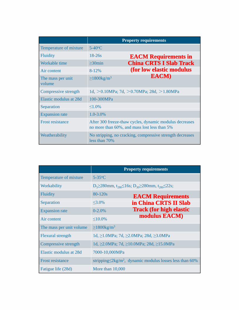
Temperature of mixture 5-40oC
Fluidity 18-26s
Workable time ≥30min
Air content 8-12%
EACMEACM Requirements in Requirements in China CRTS I Slab Track China CRTS I Slab Track (for low elastic modulus (for low elastic modulus
The mass per unit volume
≥1800kg/m3
Compressive strength 1d, >0.10MPa; 7d, >0.70MPa; 28d, >1.80MPa
Elastic modulus at 28d 100-300MPa
Separation ≤1.0%
((EACM)EACM)
p
Expansion rate 1.0-3.0%
Frost resistance After 300 freeze-thaw cycles, dynamic modulus decreases no more than 60%, and mass lost less than 5%
Weatherability No stripping, no cracking, compressive strength decreases less than 70%
Property requirements
Temperature of mixture 5-35oC
Workability D5≥280mm, t280≤16s; D30≥280mm, t280≤22s;
Fluidity 80-120s
S ti ≤3 0%EACMEACM Requirements Requirements i Chi CRTS II Sl bi Chi CRTS II Sl bSeparation ≤3.0%
Expansion rate 0-2.0%
Air content ≤10.0%
The mass per unit volume ≥1800kg/m3
Flexural strength 1d, ≥1.0MPa; 7d, ≥2.0MPa; 28d, ≥3.0MPa
in China CRTS II Slab in China CRTS II Slab Track (for high elastic Track (for high elastic
modulus EACM)modulus EACM)
g , ≥ ; , ≥ ; , ≥
Compressive strength 1d, ≥2.0MPa; 7d, ≥10.0MPa; 28d, ≥15.0MPa
Elastic modulus at 28d 7000-10,000MPa
Frost resistance stripping≤2kg/m2, dynamic modulus losses less than 60%
Fatigue life (28d) More than 10,000

CRTS II Requirement in China (for high elastic CRTS II Requirement in China (for high elastic modulus EACMmodulus EACM
Symbols in the tables:
D5 indicates the spread of mortar as slurry when it just prepared;
D30 indicates the spread of mortar stored for 30 minutes after mixing preparation;minutes after mixing preparation;
t280 indicates the time when the EACM reaches the diameter of 280mm
Factors Affecting EACM’s Factors Affecting EACM’s Compressive Strength Compressive Strength
Ratio of asphalt to cement Ratio of asphalt to cementThe viscosity of EACM increases with the ratio
increases. Sand gradation
The fluidity of EACM decreases as the fineness modulus decreasesmodulus decreases. Ratio of cement to sand Water cement ratio Admixtures, etc.

The asphalt emulsion delays cement hydration in ythe hydration process of a complex binder.
Wang, Yan, Yang, and Kong, 2011
W/C=0.60; S/C=1.5
A/C=0.3; S/C=1.5
the high elastic modulus EACM
Wang, Yan, Yang, and Kong, 2011
A/C=0.3; W/C=0.65

A/C=0.85; W/C=0.75
A slight increase was observed aswas observed as S/C increased for the low elastic modulus EACM, which may be due to the mechanical friction effect in
Wang, Yan, Yang, and Kong, 2011
friction effect in sand.
The pore size in EACM is mainly around 1000nm, much larger than that in cement paste, 60-200nm
(Hu, Zhang, and Wang, 2012)(Hu, Zhang, and Wang, 2012)

Effect of temperature on compressive strengthEffect of temperature on compressive strength
Compressive strength decreases as temperature increases.
Asphalt - Viscoelasticity
(Hu, Zhang, and Wang, 2012)(Hu, Zhang, and Wang, 2012)
Effect of temperature when exposed to waterEffect of temperature when exposed to water
(Hu, Zhang, and Wang, 2012)(Hu, Zhang, and Wang, 2012)

Effect of pressure when exposed to waterEffect of pressure when exposed to water
Water pressure
Immerse specimens into the chamber;Add one constant pressure for each specimenRecords water absorption at regular p gintervals;After 16h, cure specimens in the standard curing box (20 ±2oC, RH 60 ±5%) for 7 days;Immerse specimens into pressurized water for 5 min for the same pressure;Conduct water absorption and compressive strength tests (Hu, Zhang, and Wang, 2012)(Hu, Zhang, and Wang, 2012)
Effect of pressure when exposed to waterEffect of pressure when exposed to water
(Hu, Zhang, and Wang, 2012)(Hu, Zhang, and Wang, 2012)

Effect of temperature and pressure when exposed Effect of temperature and pressure when exposed to waterto water
ConclusionsConclusions
Water absorption increases when water temperature and/or pressure increases.
The superposition of temperature and water leads to The superposition of temperature and water leads to the performance degradation of EACM.
(Hu, Zhang, and Wang, 2012)(Hu, Zhang, and Wang, 2012)
Fastening System for Fastening System for BallastlessBallastless TrackTrack
Technical Requirements Abili k k Ability to keep track gauge Resistance to rail climbing Damping performance Insulation performance Number of components and maintenance E Evenness Capability of adjusting vertical/lateral position of rails Versatility Uniform track stiffness in turnout area

Fastening System in ChinaFastening System in China
WJ-7
Fastening System in ChinaFastening System in China
WJ-8

Fastening System in ChinaFastening System in China
Fastening system in turnout
Questions?Questions?

1
R il T kb dRailway TrackbedsMaterials Properties, Conventional Designs, and Innovative Designs
• Basic Requirements
– Track must support the loadings
and guide the train’s pathg p
• Track Quality Determines
– Permissible wheel loadings
– Safe speed of the train
– Overall safety of operations
– Dependability of operations
– FRA Class 1,2,3,4,5,6,7,8,9

2
Track Cross‐SectionRail
CrosstieBallast
• Railroad track is designed to be
Subgrade
Subballast
• Railroad track is designed to be economical and easy to maintain
Track Functions
• Guide vehicles
• Provide a high vehicle ride quality
• Withstand and distribute loadings
– Static (36 tons/axle) or
(36,000 lbs./wheel)
– Plus Dynamic (Impact)

3

4
FRA Classes of TrackPart 213 ‐‐ Subparts A to F for Class 1‐5, Subpart G for Class 6‐9

5
Class 1 Track
10 mph or less
Class 4 Track60 mph freight
80 mph passenger
Class 2 Track
25 mph freight30 mph passenger
Static Wheel Loads
(Wheel Load)(# of wheels) = Gross Weight of Car
Axle Load Gross Weight of CarsAxle load (tons) Gross weight of cars (lbs) Type
10 80,000 Light rail transit
15 120,000 Heavy rail transit
25 200,000 Passenger Cars
25 200,000 Common European freight limit
27.5 220,000 U.K. and Select European limit
33 263,000North American free interchange
limit
36 286,000Current Heavy Axle load weight for North American Class 1
39 315,000 Very limited use; research phase
Heavy Tonnage Freight

6
Wheel/Rail Contact “Patch”
The contact “patch” is about the size of a dime
=0.50 in2
Track
• Track is a dynamic system of interacting components that distributes the loads d id hand provides a smooth,
stable running surface for rail vehicles.
• System must provide vertical, lateral and longitudinal stability
132 lbrail
Dense-Graded Agg.9”wide x 7”thick x 9’ long
Ballast

7
Track Design and ConstructionDesirable Attributes:
Balance Stiffness and Resiliency f Resistance to Permanent Deformation Stability Adjustability

8
• A profitable RR must have good track.
• Track is apparently a simple structure hasTrack is apparently a simple structure, has changed little
• Loadings (pressures) must be reduced through the rail, ties, ballast and subballast to within the bearing capacity of the underlying subgrade.
Methods used to design track and cross‐section
– Trial and Error
– Empirical – based on trial and error
– Empirical/Rational – measure loadings and material properties
R ti l t / t i l i d– Rational – stress/strain analysis and measurements
• Trackbed is NOT the permanent way – varies greatly, must be maintained continuously

9
subgrade
wood tie
subballast
ballast
Beam Element
Spring
Symmetry Line
Tie
Rail
all-granular ballast trackbed
g
layer 4 bedrock
layer 3 subgrade
layer 2 sublayer
layer 1 ballast
• Requirements
– It acts as an elastic, load‐distributing structure, thus theIt acts as an elastic, load distributing structure, thus the load distribution depends on the STIFFNESS and FLEXIBILITY of the track.
– Assume a 100‐ton car: wheel load = 33,000 lbf on rail. Area of contact is assumed to be 0.5 sq in., thus contact stress is 66,000 psi static (dynamic more)
– Average subgrade will support 20 psi (1.4 ton/sq ft). Thus, the rail, ties, ballast, etc. must reduce 66,000 psi to 20 psi or problems will occur.
10
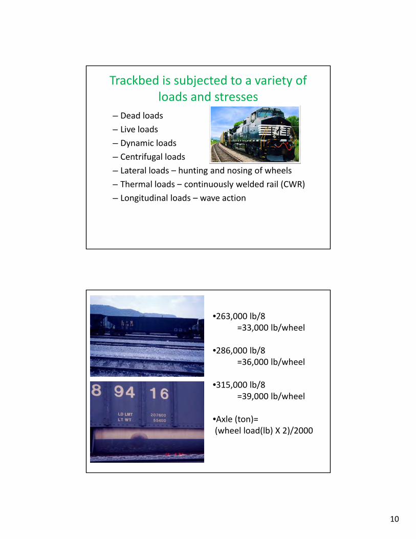
Trackbed is subjected to a variety of loads and stresses
– Dead loads
Li l d– Live loads
– Dynamic loads
– Centrifugal loads
– Lateral loads – hunting and nosing of wheels
– Thermal loads – continuously welded rail (CWR)y ( )
– Longitudinal loads – wave action
•263,000 lb/8=33,000 lb/wheel
•286 000 lb/8•286,000 lb/8=36,000 lb/wheel
•315,000 lb/8=39,000 lb/wheel
•Axle (ton)=(wheel load(lb) X 2)/2000

11
• Each component distributes the load.
– STIFFNESS (resistance to deflection)
– RESILIENCY (elasticity)
– RESISTANCE TO PERMANENT DEFORMATIONRESISTANCE TO PERMANENT DEFORMATION
• Chap 26, pages 593‐597, track geometry terms– Gage
– Line
– Surface
– STABILITY
– ADJUSTABILITY
– GOAL – safe and cost effective
• Gage (or gauge) – transverse distance between the rails measured 5/8 inch from top‐of‐rail

12
• Line – adherence of the centerline of the track
h bli h dto the established alignment and to corresponding presence or lack of irregularities or departures
• Surface – adherence to established grade and uniformity of cross‐level in the plane across the heads of the two rails and adherence to the established superelevation onsuperelevation on curves

13
TRACK ANALYSIS– Must determine allowable loads and deformations
– Must determine actual loads and deformations
– Compare and Adjust (component materials and thicknesses)
– Much early work performed by A.N. Talbot
– Many early researches idealized systems – Winkler, Westergaard, Boussinesq, etc.
– Talbot treated track as a continuous and elastically supported beamsupported beam
– Computer systems (layered analysis) have been developed recently
– Geotechnical and Pavement Design Technologies are applied
Track Stiffness (or Modulus)
– Up and down movement (pumping) of track under repetitively applied and released loads is a prime source of track deteriorationtrack deterioration.
– Design of track should keep deflection to a minimum.
– Differential movement causes wear of track components.
l f l l h f l– Modulus is defined: load per unit length of rail required to depress that rail by one unit.

14
Track Deflections: Loaded and Unloaded
Track Components
Typical “All‐Granular” Ballasted Trackbed

15
Subgrade
Use Typical S il /G t h i l
Use Typicall / h lSoils/Geotechnical
Technology
Very Important
Soils/GeotechnicalTechnology
Very Important
Subgrade
• Subgrades Vary
• EvaluateSubgrades Vary
• Evaluate
• Stabilize ???
• Top 2 feet important
Evaluate
Stabilize ???
Top 2 Feet Important

16
Subballast
• Similar to highwaySimilar to HighwaySimilar to highway base material (DGA)
• Fine grained
• Compacts tight and
Similar to HighwayBase Material (DGA)
Fine Grained
Compacts Tight and Dense
dense
Ballast
LoadingsAnchors Track
Drains
ResilienceAdjustableTransmits Loadings
Anchors TrackDrains
ResilienceAdjustable
17
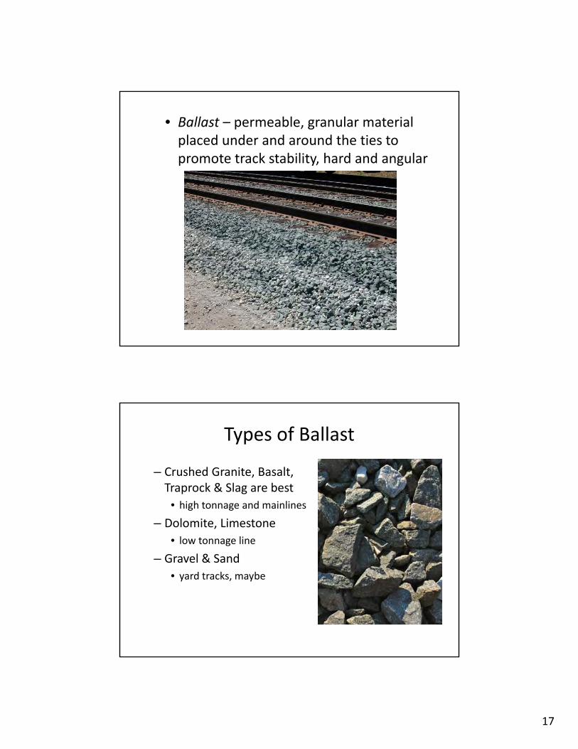
• Ballast – permeable, granular material placed under and around the ties to promote track stability, hard and angular
Types of Ballast
– Crushed Granite, Basalt, Traprock & Slag are bestTraprock & Slag are best
• high tonnage and mainlines
– Dolomite, Limestone
• low tonnage line
– Gravel & Sand
d k b• yard tracks, maybe

18
Ballast & Sub‐Ballast cross‐section*
Tie
Rails
• Ballast and sub‐ballast are the final stages in load distribution
• In addition to distributing vertical loads, ballast has a critical role maintaining longitudinal and lateral stability of track.
BallastSub-Ballast
Tie
35
• Ballast and sub‐ballast must provide adequate drainage.
• Ballast is subject to pulverization from loading and unloading as trains pass over, thereby generating fine particles that clog the ballast
* AREMA recommended practice.
Ballast Gradations
Similar to ASTM Specifications for Aggregate

19
Track Settlement and
P i
TrackSettlement and Pumping
Surface Problem (C l l)
Pumping
Surface Problem(Cross level)Surface Problem(Cross Level)

20
Profile Trouble Spots
Fouled, Muddy, Pumping Track

21
Types of Ties (Sleepers)
Timber Concrete
Composite (Polymeric) Steel
Wood(common)
Concrete(gaining popularity and use)

22
Wood Railway Ties
• Common Size– 9 in. wide– 7 in. thick– 8.5 – 9 ft. long
• Purposes
Hold the 2 rails transversely secure to correct gage– Hold the 2 rails transversely secure to correct gage
– Bear and transmit axle loads with decreased pressure
– Anchor the track
Typical Concrete Tie
• ~ 3 times heavier than wood ties, • More expensive than wood ties• Pre‐cast, Pre‐Stressed, fastenings embedded

23
Alternate Concrete Tie
Two‐Block oror
Bi‐Block
Concrete Slab Track – Direct Fixation

24
Bolted Rail /Joints versus Continuously Welded Rail (CWR)
AREMA Rail Specifications
48
• Rail specifications are maintained by AREMA• Rail size is measured in lbs./yard of length• Most common new rail is 115 lb., 136 lb., & 141 lb.• Type – Standard, Intermediate*, Premium

25
Types of Steel Rail• Standard Medium Carbon
• Head Hardened
• Fully Heat Treated
Al Hi Si CHRO/MOLY d B i i i• Also Hi Si, CHRO/MOLY and Bainitic
Intermediate Hardness Rail ???????
Rail Stamping
133‐lb rail, meeting AREMA specs, head hardened, vacuum treated, NKK Company, rolled in 1996 – March

26
Continuously Welded Rail (CWR)
• 1440 ft. sections
• Advantages• AdvantagesMany
• DisadvantagesFew
United States Applications
Since 1981
• Short Maintenance—Road Crossings, Turnouts, Rail Crossings, Tunnels, Bridge Approaches, WILDS, etc.Approaches, WILDS, etc.
• Capacity Improvement—Double Tracking, Line Changes, etc.
27

28
SW Durham Rd. May 15‐16, 2010

29

30

31
International ApplicationsItaly France Germany
Japan Spain AustriaJapan Spain

32
Italy
• Rome‐Florence: 252 km (1977 1986)(1977‐1986)
• Debated between cement and asphalt
• Asphalt – designated on all future high‐speed passenger linespassenger lines
• Prevents rainwater from infiltrating the layers below the embankment
• Eliminate high stress loads and failures of the embankmentembankment
• Protect the upper part of the embankment from freeze/thaw actions
• Gradually distribute static and dynamic stresses caused by trainsby trains
• Eliminate ballast foulingBuonanno, 2000

33
Typical Cross Section
• 12 cm of asphalt with 200 MPa modulus
• 30 cm of super compacted subgrade with 80 MPa modulus
• 35 cm of ballast on top

34
Policicchio, 2008
Teixeira, 2005

35
Japan
• Widely Used
Hi h S d/R l• High Speed/Regular
• Firm Support for Ballast
• Reduce Load Level on Subgrade
• Facilitate Drainage
Momoya and Sekine, 2007

36
• Performance Rank I: Concrete roadbed or asphalt roadbed for ballastless track– Concrete base thickness = 190 mm
– Asphalt base thickness = 150 mm
– Stone base thickness = 150 mm
• Performance Rank II: Asphalt roadbed for ballasted track– Ballast thickness = 250‐300 mm
– Asphalt base thickness = 50 mm
– Stone base thickness = 150‐600 mm
• Performance Rank III: Crushed stone roadbed for ballasted track

37
Ballastless Cross Section
• Mainly used for viaducts and tunnelsviaducts and tunnels
• Proposed a low noise solid bed track on asphalt pavement
Ballasted Cross Section
• Asphalt Thickness:
55 cm
• Well‐Graded Crushed Stone Thickness:
15‐60 cm

38
France
• Paris to Strasbourg high speed linehigh‐speed line
• 3 km asphalt subballast
• 574 km/hr (357mph) (test)
Comparative Cross‐Sectional Profiles

39
• Reduces overall cross‐sectional thickness by 36 cm
• Reduces quantity of fill material byReduces quantity of fill material by
5,000 cubic meters/ kilometer
Bitume Info, 2005

40
Testing
• Conduct tests for 4 years (2007‐2011)
• Temperature sensors continuously recording air temperature
• Pressure Sensors and Strain Gages checked twice a year
• Accelerometers• Accelerometers
Spain
• Madrid – Valladolid
• Barcelona – French Border

41

42
Germany
• Utilize several alternatives toalternatives to conventional ballast design
• German Getrac A1/A3 –ballastless slab consisting of asphaltconsisting of asphalt
• Concrete ties are anchored to the asphalt

43

44
Austria
Reasons for Implementing Asphalt Layers
How to install an Asphalt Layer?
to allow road vehicles running on the sub‐layer during construction phase
Targets of an Asphalt Layer
y g pindependently from weather and sub‐soil situation
clear separation of sub‐ and superstructure during the whole service life
Advantages
drainage effect for raining water hinderingit penetrating the substructure
avoiding the pumping up of fines into the ballast delivering a certain amount of elasticity homogenising the stresses affecting the substructure

45
Long Term ExperiencesJauntal, Carinthia
ConclusionsAsphalt layers improve the quality of track in defining a clear and long lasting separation between superstructure and sub‐structure. This separation results in less maintenance demands of track and (thus) longer service lives.( ) g
These benefits must be paid by an additional investment of 10€/m² within the initial construction.
Life cycle cost analyses show that it is worth to implement asphalt layers on heavy loaded lines (> 15,000 gt per day and track), as then the annual average track cost can be reduced by 3% to 5%.
However, implementation of asphalt layers cannot be p p yproposed for branch lines carrying small transport volumes.Asphalt Layers must be understood as an additional investment in quality, then it pays back its costs. It must not be implemented in order to reduce quality in sub‐layers, by for example reducing the thickness of the frost‐layers.

46
D t th l i t ti f ti i t lli f h lt l
ImplementationConsequently asphalt layers of 8 cm to 12 cm form astandard element for new high capacity and highspeed lines in Austria.Due to the long interruption of operation installing of asphalt layers arenot proposed within track re‐investment and maintenance operations.
Picture a to c: new Koralm link
Picture d: Schoberpass‐line, built in 1991