Embed Size (px)
Citation preview

PROK DEVICES PRIVATE LIMITED B-80, 2nd & 3rd Floor, KSSIDC Industrial estate, 4th Main Road,
6th Block, Rajaji Nagar, Bengaluru -560010 Ph no: 080-41480777, 080-41157700,
Email: [email protected],www.prokdvs.com, www.prokdvs.in
NUMERICAL UNDER+OVER VOLTAGE RELAY
AND NEGATIVE PHASE SEQUENCE PROTECTION
(TYPE: PNV-NSP)
Introduction Prok dv’s make micro-controller based PNV Series, PNV-NSP Voltage Relay is a combination of Over Voltage and Under voltage with the detection of Negative and Positive sequence voltage with instantaneous elements on under, over & negative sequence. The relay offers reliable and flexible solutions for the protection of Power Plants, Feeders, Motors, Generators, Transformers, grounded and ungrounded systems etc., against voltage variations. It incorporates IDMT characteristics, Definite time characteristics and High Speed/Instantaneous feature for over voltage and under voltage settings and also the negative sequence protection. It has user-friendly feature for entry of parameters by using membrane key pad and LCD display having 2 line, 16 character alpha-numeric display. It operates on the principle of detection of Negative and Positive sequence voltages to measure the degree of unbalance in the system voltages. Once the unbalance voltages exceed the set limit, time delay required to issue the trip command is evaluated. Over voltage, Under voltage and relay trip conditions are indicated by LED’s Aux. Supply is provided by Universal Switch Mode Power Supply(SMPS) with input voltage being either AC or DC, 85- 275 AC/DC or 30V to 110V DC. In case of AC voltages the power supply is designed to operate from 47Hz to 53 HZ. The relay has been housed in a non draw-out case with front transparent poly carbonate cover for dust proof and the relay has both LCD and LED indications for Fault identifications, along with external mechanical reset switch. The relay confirms to IEC 60255.

BLOCK DIAGRAM
Features: IDMT & Definite Time Characteristics High Pick up/ Drop off ratio EEPROM-memory for data retention Wide range of system voltages High speed feature for Under, Over Voltages & Negative sequence 2 LINE, 16-character LCD display and Membrane keypad Very low burden on AC and DC(Auxiliary and Sensing) Accurate and reliable measurement of voltages by measuring negative sequence
voltages by using DFT Built in test facility Magnitude of Fault & Nature of Fault Indication in LCD Display(RMS Value of
Voltages) LED Indication for nature of faults Site selectable voltages 0-220/0-230/0-240/0-250 Volts, 50Hz, 3 Phase 4 wire
system

Working Principle
The relay employs DFT-technique for the detection and measurement of negative and
positive sequence voltages. The system voltages that is to be monitored is stepped to a
suitable level by the input of built in potential transformers. This signal is passed through
a low pass filter (LPF) to band/limit the signal, the output of the LPF is passed through a
variable gain amplifier and level shifter, this process of signal conditioning prepares the
signal to be applied to the Microcontroller.
The microprocessor samples the signal and converts it to a digital value.. Once the
signal is in the form of digital data, DFT- technique is employed to extract magnitude
and phase angle of the input signal.
When the measured values of voltages and negative sequence component, crosses the
set values entered by the user, tripping times for the relay are calculated according to
the characteristic selected and trip command is issued by the relay for necessary action.
The schematic diagram of the relay is as shown in the following block diagram.
Setting procedure:
The following block shows keypad, display and LEDs in the front fascia, Keypad is used
for accessing and making setting for the relay.
The following section gives the complete setting procedure for the relay:
Connect the rated Auxiliary Voltage for the relay(marked on the rear side of the
relay) and when connecting a DC-Voltage Source observe the correct polarity
Use I OR Key to change the setting values
Press Key to change the setting values will not be registered in the
memory of the relay unit.
While entering values/making changes the process has to be completed within a
span of 30seconds. Failing to observe this will force the relay to come out of the
setting mode.
Once the Aux. Voltage is connected, the display shows
the following:
PNV-NSP Model Name
Un System Voltage
Also the GREEN LED marked as ON will be indicating the presence of Aux.
Input voltage.

Setting procedure details:
Accessing the relay: Press and key simultaneously, the release
SET/F-RST key first then release START key, display shows the following:
Rated Voltage
This system voltage is selectable by user
Select a suitable system voltage by operating key and key, Press
to register the selected value.
After selection of the system voltage the display shows over voltage-Low setting
option.
Previous or factory set Range of Over Voltage to be selected (Low set)
Now enter the Over Voltage[O>] settings for the system(step of 0.01).
.
After the selection of the Over Voltage the user will be given the to select either
the or
Characteristics Selection
Select either Definite Time or IDMT Characteristic by operating the
key.
If the selected characteristics is Definite Time, then the display
Shows:
Previous or Range of time
Factory set to be selected

Now the time of operation of the relay (in Secs.) is selected in the given
range(step of 1sec.) After the selection press to register the selected time.
Now the display changes
This is High-set option for the system, the user has to select suitable High-set
voltage within the range(step of 0.01) and press key to register the value.
Now the display changes to
This is the permitted time range (in Secs.) for High set, select a suitable time for
high set operation and enter to record the selected time(step 0.01). This
completes the entry of the parameters for Over voltage conditions. After the
selection of time for the High set, display changes to
Previous or Range of Under voltage
Factory set value to be selected (Lowest)
With display showing the range of low-set under voltage for the system[U<],
Under voltage conditions for system are selected and this value is recorded by
pressing key. After this display shows the option for selection of Definite
Time or IDMT Curve
or
Characteristics Selection
If the selected characteristic is Definite Time, then display shows
Previous or Range of time
Factory set to be selected
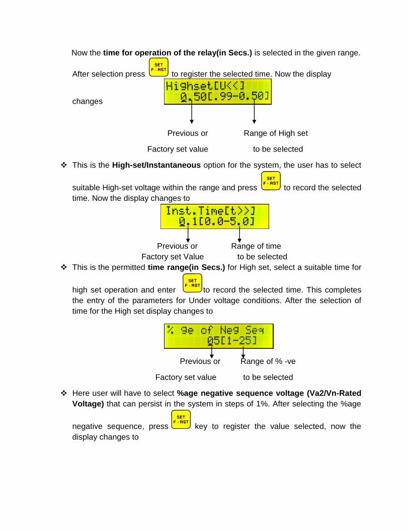
Now the time for operation of the relay(in Secs.) is selected in the given range.
After selection press to register the selected time. Now the display
changes
Previous or Range of High set
Factory set value to be selected
This is the High-set/Instantaneous option for the system, the user has to select
suitable High-set voltage within the range and press to record the selected
time. Now the display changes to
Previous or Range of time
Factory set Value to be selected
This is the permitted time range(in Secs.) for High set, select a suitable time for
high set operation and enter to record the selected time. This completes
the entry of the parameters for Under voltage conditions. After the selection of
time for the High set display changes to
Previous or Range of % -ve
Factory set value to be selected
Here user will have to select %age negative sequence voltage (Va2/Vn-Rated
Voltage) that can persist in the system in steps of 1%. After selecting the %age
negative sequence, press key to register the value selected, now the
display changes to

Previous or Rate of time
Factory set value to be selected
Now the time of operation for %age negative sequence voltage in definite time
mode is to be selected in the given range and press key, display
momentarily shows
Previous or Rate of time
Factory set value to be selected
Here, the user can select the time of operation(Definite time) of the relay if the
negative sequence crosses more than 25% in the system, after the time
selection, press key, display momentarily shows
After the momentary display of updating the data, display will show the system
voltage selected along with the model of the relay and type of system
This completes the procedure for setting the relay when the selected model of
operation of the relay is in definite time for over and under voltage conditions.
The relay can also be programmed to act as IDMT relay for Over and Under
Voltage conditions by following almost similar setting procedure. The
complete steps are indicated below:
Accessing the relay: Press and key simultaneously, the release
key first then release key, display shows the following:

This system voltage is
selectable by the user
System Voltage 3 Phase 4 Wire system
Select a suitable voltage by operating Increment key and Decrement key
Press key to register the selected value. After selection of the system
voltage the display shows
Previous Range of
Factory set value Low set
Now the user can enter the Over Voltage[0>] setting for the system
After the selection of the Over Voltage limit press key, the user will be
given the option to select either the
or
Characteristics Selection
III. Now select the relay to function as IDMT relay by selecting the IDMT
characteristics, for this operate / key and when the display shows IDMT-
option select it by pressing key. After selecting the IDMT characteristics the
display shows
Previous or Time multiplier range
Factory set Value to be selected
Now the time multiplier for Over Voltage IDMT- curve can be selected. After

the selection of Time multiplier press the key to enter the value. The display
changes to
Previous or Range of High set
Factory set Value to be selected
This is the High-set option for the system, the user has to select High-set voltage
within the range and press key to register the value. Now the display changes to
Previous or Range of time
Factory set to be selected
This is the permitted time range (in Secs.) For High set, select a suitable time
for high set operation and enter to record the selected time. This
completes the entry of the parameters for Over voltage conditions. After the
selection of time for the High set, display changes to
Previous or Range of Under voltage
Factory set Value to be selected
With display showing the range of Under Voltage conditions for the system [U<] Under voltage conditions for system are selected and this value is recorded
by pressing key. After this the display shows the option for selection of
or
Characteristics Selection

Select IDMT-characteristics for Under voltage by operating / keys,
once the IDMT- option is shown, select it by pressing key
IV. If the selected characteristic is IDMT Curve for Under voltage, then, display
shows
Previous or Time multiplier range
Factory set to be selected
Now the time multiplier for the IDMT curve is selected in the given range. After
selection, press to register the selected time. Now the display changes to
Previous or Range of High set
Factory set to be selected
This is the High-set option for the system, the user has to select a suitable
High-set Voltage within the range and press key to register the value. Now
the display changes to
Previous or Range of Time
Factory set to be selected
This is the permitted time range(in Secs.) for High set, select a suitable time for
high set operation and enter to record the selected time. This completes the entry parameters for Under voltage conditions. After the selection of time for High set, display changes to

Previous or Range of % -ve
Factory Set Sequence to be selected
Here, user will have to select %age negative sequence voltage(Va2/Vm) that
can persist in the system in steps of 1%. After selecting the %age negative
sequence, press key to register the value selected, now the display
changes to
Previous or Range of time Factory set value to be selected
Now the time of operation for %age negative sequence voltage in definite
time mode is to be selected in the given range and press key, display will
show
Previous or Range of time Factory set value to be selected
Here, the user can select the time of operation(Definite time) of the relay if the negative sequence crosses more than 25% in the system, after the time selection
press key, display momentarily shows
After the momentary display of updating the data, display will show the system
voltage selected along with the model of the relay and type of system
After the above display is displayed

This completes the procedure for setting the relay when the selected mode of
operation of the relay is IDMT relay for Over voltage and Under voltage
conditions.
Then it displays all the voltages with respect to neutral & RMS value, then the
display is as follows
SPECIFICATIONS:
Rated Un 380V, 400V, 415V, 433V
System voltages 0-220, 0-230,0-240& 0-250V AC
50 Hz, 3 phase 4 wire system
Frequency Range 47.00Hz to 53.00Hz AC
SETTING RANGE:
Under voltage U<0.99 to 0.5Un[IDMT-Curve] in steps of 0.01
TMS-0.1 to 1.00(step-0.1)
DEFT Time 0 to 300sec(step-1 sec)
High speed UV U<<0.99 to 0.50Un [High speed] in steps of 0.01
Over voltage U>1.01 to1.30Un[IDMT-Curve] in steps of 0.01
TMS- 0.01 to 1.00(Step-0.1)
High Speed OV U>>1.01 to 1.30Un[High Speed] in steps of 0.01
Time 0.0 to 5.0sec
Negative Sequence 1 to 25% in steps of 1%
[Unbalance Voltage] DEFT Time 0 to 300sec(Step-1 sec)
Above 25% Instantaneous <30ms
Time for NS>> 0.0 to 5.0 sec(Step-0.1 sec)
PICK-UP & DROP OUT:
Pick Up Over Voltage: 101% of the set value
Under Voltage: 99% of the set value
Drop Out Over Voltage: 99% below pick-up value
Under Voltage: 101% above pick-up value
Desired drop off value can be tailored as per customer
request
Instantaneous < 30ms +/- 5%
Response time
Aux. Supply 85 to 275V AC/DC or 21 to 110V DC

AC Burden <1VA
DC Burden 10Watt operation condition, 6Watt un-operated condition
Contacts 2 pair of Changeover contacts for IDMT/DFT/NSP
2 pair of Changeover contacts for High speed
Contact Rating Making:
5A make & carry at 240V AC
Breaking:
5A make & carry at 24V DC
Casing Front Poly carbonate
Transparent cover with external hand reset
Dimension W 155mm X H 180mm X D 200mm, Tolerance +/- 1mm
Panel Cut out W 151mm X H 157mm Tolerance +/-1mm
TESTS:
Insulation 2kV RMS 50Hz for 1minute
As per IEC 60255-5, clause 5 & 6
HFD As per IEC 6025-22-1, CL-3
Impulse Voltage As per IEC 60255-5 Clause 5 & 8
Temperature -5 degree to + 55 degree Cent.
CHARACTERISTICS:
IDMT Over Voltage , t=k/log[ovf]
Under Voltage t=k/log[2-uvf]
K= time dial setting with range 0.1 to 1.0sec in steps of 0.1
Ovf= Measured Value / (Set value x Rated Voltage)
Uvf= Measured Value / (Set Value x Rated Voltage)
Definite Time 0 to 300sec. [Time setting in steps of 1]
High Speed 0.0 to 5sec [Time Setting in steps of 0.1]

FRONT FASCIA
Represents that the relay withstood and tested for High voltage dielectric and
inside number represents the level of voltage
Represents that relay withstood and tested for High voltage impulse and inside
the number represents the level of voltage
Represents that ‘refers to Manual’

TERMINAL DIAGRAM FOR PNV-NSP
NON-DRAWOUT TERMINAL & WIRING DETAILS

TERMINAL WIRING DIAGRAM

MECHANICAL DIAGRAM

WIRING DIAGRAM