Embed Size (px)
Citation preview

8
Numerical Study on the Surface Depression of the
Concrete Runway Pavement under Impact Load
Saima Ali, Xuemei Liu, Sabrina Fawzia School of Civil Engineering and Built Environment
Queensland University of Technology, Brisbane, Australia
International Journal of Research in Civil Engineering, Architecture & Design
Volume 4, Issue 1, January-March, 2016, pp. 08-19
ISSN Online: 2347-2855, Print: 2347-8284, DOA: 15022016
© IASTER 2016, www.iaster.com
ABSTRACT
Airport runway pavement always subjected to huge impact loading due to the hard landing of aircraft
on the pavement surface. Therefore runway pavements should have sufficient impact resistance
capability to avoid damage causing by hard impact like surface deflection in downward or
penetration since the repair works is cumbersome within the operating condition of airport and also
increases the service life cost of the pavement structure. Several research works have been carried
out on airport runway pavement to measure the present condition of pavement and also to predict
future performance of it. However, most of the works are confined by pavement response under
moving aircraft loading. Nevertheless, no comprehensive research work is yet conducted to identify
the controlling factors which might have significant effect in changing the common pavements
damage like surface penetration depth under impact of aircraft. Therefore, a 3DFE study is
conducted to determine some effective factors in controlling the top surface penetration depth of
runway pavement. Among the exterior factors, mass of the impactor, velocity of the impactor, impact
angle and boundary conditions are selected and as interior factors, thickness of the runway pavement,
compressive strength and density of materials used in the runway pavement are selected.
Keyword: Surface Depression, Fracture Energy, Impact Angle, Compressive Strength, Strain Rate Effect.
I. INTRODUCTION
Airport runway pavement always encounters large impact loading during the landing of heavy
aircraft. Exceptionally large and heavy aircrafts have also been introduced to fulfill the travel demand
thatcould exert heavy impact force on runway pavement. The consequence of such impact causes
penetration or depression at certain adjacent region of the top surface layer of runway pavement. The
extent of damage can vary with factors such as the weight of aircraft, velocity of aircraft, landing
angle of aircraft, and also factors including material property and thickness of the runway pavement.
Extensive research works have been carried out to investigate the deterioration of runway pavement
and to propose solutionsmainly for such pavement under moving aircraft load. Kim and Tutumluer [1]
conducted a finite element (FE) study to explore the multiple wheel load interaction effects on the
flexible runway pavement instead of single wheel load condition under moving aircraft load. In
addition, Su et al. [2] investigated the significance of using recycled asphalt concrete in the surface
layer of airport runway pavement. A full scale laboratory program with wheel tracking test and 3-
point bending test was carried out and the properties of recycled asphalt concrete for short term and
long term ageing were tested and compared with the original asphalt concrete. Al-Qadi et al. [3]
carried out a rigorous in situ test program at Cagliari-Elmas airport in Italy to investigate the stresses
International Journal of Research in Civil Engineering, Architecture & Design
Volume-4, Issue-1, January-March, 2016, www.iaster.com ISSN
(O) 2347-2855
(P) 2347-8284
9
and strains of flexible runway pavement under moving aircraft load. In addition, Khanna et al. [4]
used impulse response (IR) method to provide an authentic measure of present and future state of
pavement and the data was recorded at 81 general aviation airport in Oklahoma. Besides,
Gopalakrishnan and Thompson [5] investigated the effects of full scale heavy aircraft loading on the
unbound aggregate and fine grained subgrade layer in field condition.Moreover, Kim and Buttler [6]
conducted study to predict the crack propagation in airport pavement under the combined effect of
aircraft landing forces and thermal conditions. In addition, Rufino et al. [7] conducted a rigorous
experimental investigation on at Denver International Airport to investigate the phenomenon of slab-
base interaction and to measure strain on runway pavement under wheel load of aircrafts. Again, Yan
et al. [8] investigated the interlayer bond condition of double layer airport pavement by using splitting
tensile test with double layer beam arrangement. Besides, Taheri et al. [9] investigated dynamic
interaction between moving aircraft B-727 and concrete pavement. A general algorithm was
developed which was based on structural impedance approach and utilized influence functions.
Besides, few studies are also conducted on delamination analysis for runway pavement. For instances,
Hoegh et al. [10] suggested the use of ultrasonic tomography device for a pavement section as well as
new and old asphalt layers and Maser and Sande [11] recommend ground penetrating radar in airfield
condition to detect the category and intensity of delamination. Moropoulou et al. [12] suggested the
use of infrared thermography technique to locate delamination in airport pavement. A few number of
research works were also conducted to study the effect of impact loading. Kuo et al. [13] studied the
effect of inclined impact loading caused by hard landings of heavy aircraft in developing fatigue
cracks on runway pavement. Besides, Buonsanti and Leonardi [14] developed a 3D model to
determine the contact stress at flexible runway pavement when the aircraft hit the pavement with
heavy impact. However, no rigorous study is yet conducted to understand the influential factors which
could cause surface damage like penetration in runway pavement under hard impacts of aircrafts.The
identification of significant factors accelerating the surface depression is the preliminary crucial steps
which can lead to a successful design of runway pavement with minimum maintenance.
Evaluating the different parameters’ influence on the infrastructures the dynamic response under impact
through full scale tests is often beyond the affordability. Numerical simulation is normally adopted to
predict the dynamic response of the infrastructure subjected to impact loadings with varied parameters.
Therefore, a comprehensive numericalstudy is conducted to determine the significant influential
parameters responsible for top surface penetration depth of runway pavement.This study starts with the
validation of the numerical model on concrete pavement with experimental investigation from Wu [15].
To conduct this, a 3D FE model is developed using ABAQUS 6.13-3. After the validation, a rigorous
parametric study is conducted to evaluate the effect of different parameters on the performance of
runway pavement under impact loading especially on the surface penetration depth of runway pavement.
And those parameters includeimpact velocity, impactor mass, angle of impact, thickness of pavement,
and compressive strength of materials used in runway pavement.
II. FE MODELLING
i) General
In this study, a 3D FE model is built in the ABAQUS/Explicit to validate the impact test conducted by
Wu [15]. The model is composed of 275 mm thick concrete slab over subgrade.The subgrade is 600
mm thick and composed of sand. The concrete specimen is 900 mm × 900 mm in dimension and the
dimension of the underneath subgrade is 1m × 1 m (Figure 1). To resist the uplift of the two parallel
sides of the concrete slab, two textile belts are used near the edges over top surface of concrete slab.
Hemispherical drop mass is used to apply the impact load at the mid-point of the top surface of
International Journal of Research in Civil Engineering, Architecture & Design
Volume-4, Issue-1, January-March, 2016, www.iaster.com ISSN
(O) 2347-2855
(P) 2347-8284
10
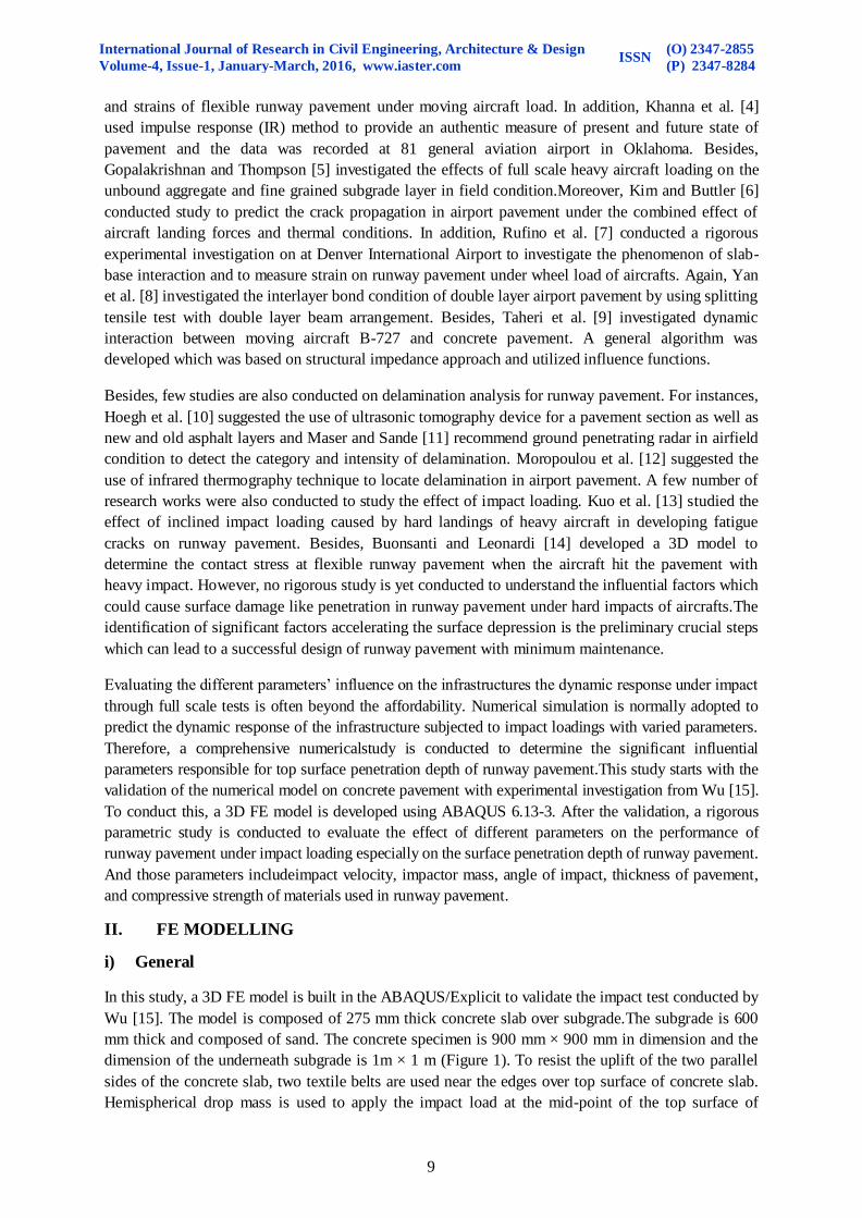
concrete slab. The diameter of the drop mass is 100 mm and the length of the drop mass is 1.292 m.
The impact velocity applied by the drop mass is 5.133 m/s. The material properties used in the
analysis of FE model are given in Tables 1- 3.
Table 1: Mechanical Properties of Concrete Slab
Parameters Value Young’s modulus, E (GPa) 33
Poisson’s ratio, ʋ 0.2
Density, ρ (Kg/m³) 2400
Compressive strength, fc (MPa) 54
Tensile strength, ft (MPa) 2.7
Table 2: Mechanical Properties of Subgrade
Parameters Geocell Reinforced Sand Sand Young’s modulus, E (MPa) 103.5 40
Poisson’s ratio, ʋ 0.3 0.3
Density, ρ (Kg/m³) 1600 1600
Friction angle, β 40º 40º
Cohesion, c (KPa) 89 13.8
Table 3: Mechanical Properties of Drop Mass/ Impactor and Textile Belt
Parameters Impactor Textile belt Young’s modulus, E (GPa) 207 2.1
Poisson’s ratio, ʋ 0.3 0.3
Density, ρ (Kg/m³) 118000 1000
Yield strength, fy (MPa) 500 80
Tangent modulus _ 39000
Erosion strain _ 0.006
Figure 1: Experimental Set Up of Concrete Pavement with Subgrade [15]
i) Element Selection and Material Modeling
a) Concrete Slab
The concrete slab is modeled with 8-node linear brick elements (C3D8R) with reduced integration
and hourglass control. Concrete slab was considered as isotropic and concrete damage plasticity
model available in ABAQUS/Explicit is used to simulate the elasto-plastic behaviour of concrete slab.
The properties used for concrete slab is given in Table 1. The elastic parameters are selected
according to Wu [15] and plastic parameters are considered by following Fujita and Ishimaru [16] and
also standard values of ABAQUS/6.13-3. Typical concrete compressive stress-strain curve for
275 mm thick
Concrete Slab
International Journal of Research in Civil Engineering, Architecture & Design
Volume-4, Issue-1, January-March, 2016, www.iaster.com ISSN
(O) 2347-2855
(P) 2347-8284
11
specified strength of concrete slab is used to get the yield stress and the corresponding crushing or
inelastic strain values under uniaxial compressive loading. Similarly, concrete tensile strength curve
as given in Ozbolt et al. [17] is used to get the yield stress and the corresponding cracking strain
values. However, dynamic impact load usually imposes high strain on materials and thereby the
consideration of strain rate effect is essential. Preliminary FE analysis is conducted on concrete slab
under specified impact loading to determine the strain at which the concrete slab undergoes and
following it the strain rate effect is applied accordingly by using dynamic increase factor (DIF) curve.
b) Subgrade
The subgrade is also modeled with 8-node linear brick elements (C3D8R) with reduced integration
and hourglass control. The elasto-plastic behaviour of subgrade soil is simulated by using Drucker-
Prager plasticity model. The properties used for geocell reinforced and normal subgrade sand is given
in Table 2. The dilation of soil is not considered in the FE model. The elastic parameters are used
according to Wu [15] and plastic parameters are selected by following Wu [15], Mijangos and Kelly
[18] and also Houlsby [19].
c) Impactor/Drop mass and Textile Belt
The impactor is modelled by using 10-node modified second order elements (C3D10M) with reduced
integration and hourglass control due to greater stiffness of this element and also to adjust with the shape
of the hemispherical head of the impactor. The mechanical properties of impactor are used as given in
Wu [15]. However, textile belt is included in FE model on the edge of top surface of concrete as
described in experimental set up of Wu [15]. 4-node quadrilateral membrane elements (M3D4R) with
reduced integration and hourglass control is used to model textile belt.. The plastic-kinematic model is
also adopted to simulate the bi-linear behaviour of textile belt. The plastic option of ABAQUS/6.13-3 is
selected and kinematic hardening is used to implement the plastic-kinematic model of textile belt. The
detail properties of cylindrical shaped hemispherical impactor and textile belt as used byWu [15] are
given in Table 3. The plastic properties are collected from Carvelli et al. [20].
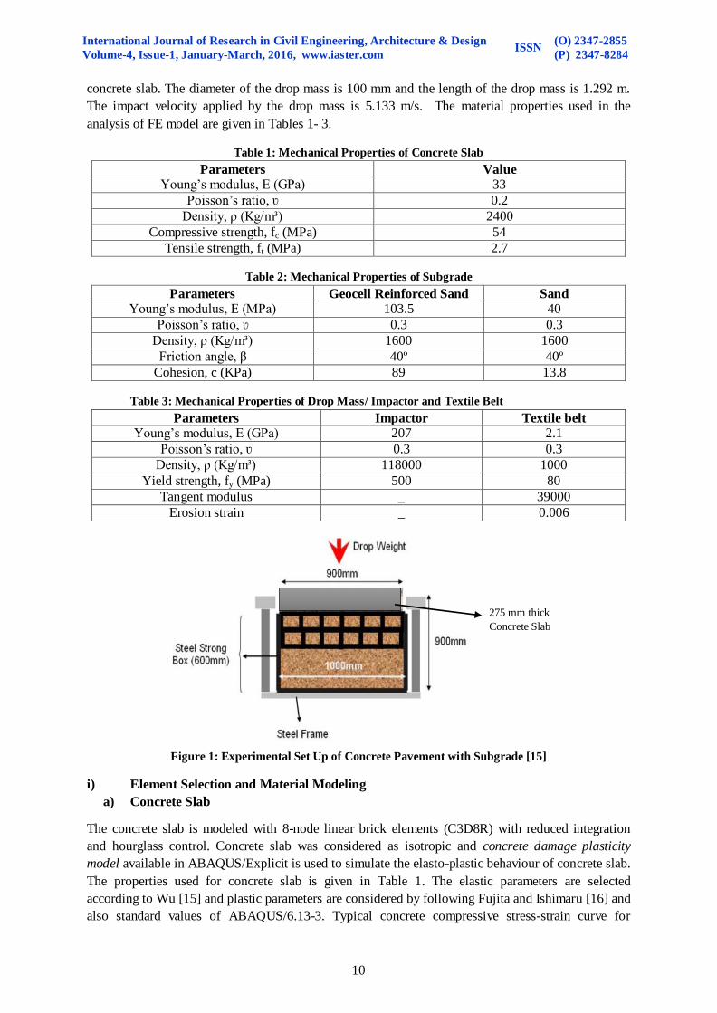
d) FE meshing and Contact Modelling
The selection of proper mesh size of FE model is important for accurate analysis results and more
importantly for high strain
loading. For overall model,
small mesh size is selected for
better result. Comparatively
finer mesh size is selected for
concrete slab compared to the
subgrade since concrete slab is
directly subjected to impact
load. The mesh size is found as
suitable when 5 mm mesh size
is adopted for concrete slab and
8 mm mesh size adopted for
subgrade. The mesh size
selected for the textile belt is 10
mm. Figure 2 shows the FE
meshing distinctly.
Figure 2: FE Meshing in a Single Layer Pavement Specimen
International Journal of Research in Civil Engineering, Architecture & Design
Volume-4, Issue-1, January-March, 2016, www.iaster.com ISSN
(O) 2347-2855
(P) 2347-8284
12
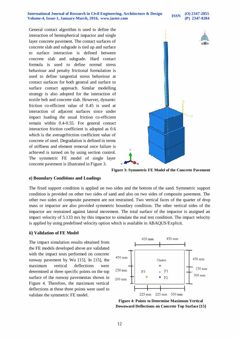
General contact algorithm is used to define the
interaction of hemispherical impactor and single
layer concrete pavement. The contact surfaces of
concrete slab and subgrade is tied up and surface
to surface interaction is defined between
concrete slab and subgrade. Hard contact
formula is used to define normal stress
behaviour and penalty frictional formulation is
used to define tangential stress behaviour at
contact surfaces for both general and surface to
surface contact approach. Similar modelling
strategy is also adopted for the interaction of
textile belt and concrete slab. However, dynamic
friction co-efficient value of 0.45 is used at
interaction of adjacent surfaces since under
impact loading the usual friction co-efficient
remain within 0.4-0.55. For general contact
interaction friction coefficient is adopted as 0.6
which is the averagefriction coefficient value of
concrete of steel. Degradation is defined in terms
of stiffness and element removal once failure is
achieved is turned on by using section control.
The symmetric FE model of single layer
concrete pavement is illustrated in Figure 3.
Figure 3: Symmetric FE Model of the Concrete Pavement
e) Boundary Conditions and Loadings
The fixed support condition is applied on two sides and the bottom of the sand. Symmetric support
condition is provided on other two sides of sand and also on two sides of composite pavement. The
other two sides of composite pavement are not restrained. Two vertical faces of the quarter of drop
mass or impactor are also provided symmetric boundary condition. The other vertical sides of the
impactor are restrained against lateral movement. The total surface of the impactor is assigned an
impact velocity of 5.133 m/s by this impactor to simulate the real test condition. The impact velocity
is applied by using predefined velocity option which is available in ABAQUS/Explicit.
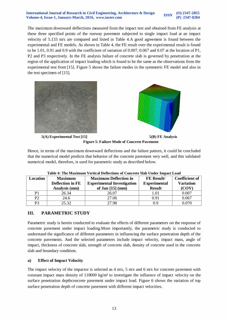
ii) Validation of FE Model
The impact simulation results obtained from
the FE models developed above are validated
with the impact tests performed on concrete
runway pavement by Wu [15]. In [15], the
maximum vertical deflections were
determined at three specific points on the top
surface of the runway pavementas shown in
Figure 4. Therefore, the maximum vertical
deflections at these three points were used to
validate the symmetric FE model.
Figure 4: Points to Determine Maximum Vertical
Downward Deflections on Concrete Top Surface [15]
International Journal of Research in Civil Engineering, Architecture & Design
Volume-4, Issue-1, January-March, 2016, www.iaster.com ISSN
(O) 2347-2855
(P) 2347-8284
13
The maximum downward deflections measured from the impact test and obtained from FE analysis at
these three specified points of the runway pavement subjected to single impact load at an impact
velocity of 5.133 m/s are compared and listed in Table 4.A good agreement is found between the
experimental and FE models. As shown in Table 4, the FE result over the experimental result is found
to be 1.01, 0.91 and 0.9 with the coefficient of variation of 0.007, 0.067 and 0.07 at the location of P1,
P2 and P3 respectively. In the FE analysis failure of concrete slab is governed by penetration at the
region of the application of impact loading which is found to be the same as the observations from the
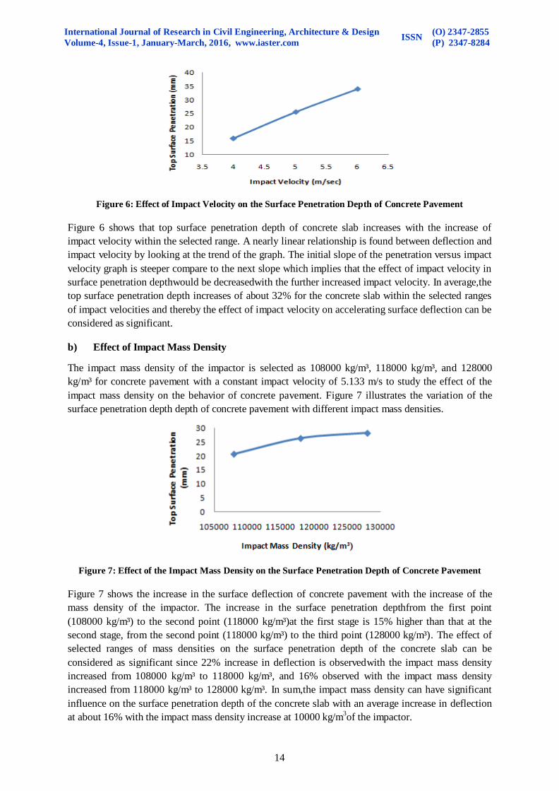
experimental test from [15]. Figure 5 shows the failure modes in the symmetric FE model and also in
the test specimen of [15].
5(A) Experimental Test [15] 5(B) FE Analysis
Figure 5: Failure Mode of Concrete Pavement
Hence, in terms of the maximum downward deflections and the failure pattern, it could be concluded
that the numerical model predicts that behavior of the concrete pavement very well, and this validated
numerical model, therefore, is used for parametric study as described below.
Table 4: The Maximum Vertical Deflections of Concrete Slab Under Impact Load
Location Maximum
Deflection in FE
Analysis (mm)
Maximum Deflection in
Experimental Investigation
of Jun [15] (mm)
FE Result/
Experimental
Result
Coefficient of
Variation
(COV)
P1 26.34 26.07 1.01 0.007
P2 24.6 27.06 0.91 0.067
P3 25.32 27.98 0.9 0.070
III. PARAMETRIC STUDY
Parametric study is herein conducted to evaluate the effects of different parameters on the response of
concrete pavement under impact loading.More importantly, the parametric study is conducted to
understand the significance of different parameters in influencing the surface penetration depth of the
concrete pavements. And the selected parameters include impact velocity, impact mass, angle of
impact, thickness of concrete slab, strength of concrete slab, density of concrete used in the concrete
slab and boundary condition.
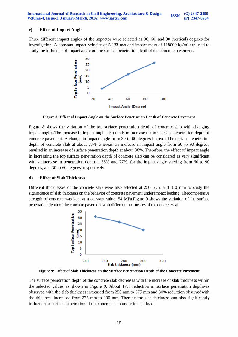
a) Effect of Impact Velocity
The impact velocity of the impactor is selected as 4 m/s, 5 m/s and 6 m/s for concrete pavement with
constant impact mass density of 118000 kg/m³ to investigate the influence of impact velocity on the
surface penetration depthconcrete pavement under impact load. Figure 6 shows the variation of top
surface penetration depth of concrete pavement with different impact velocities.
International Journal of Research in Civil Engineering, Architecture & Design
Volume-4, Issue-1, January-March, 2016, www.iaster.com ISSN
(O) 2347-2855
(P) 2347-8284
14
Figure 6: Effect of Impact Velocity on the Surface Penetration Depth of Concrete Pavement
Figure 6 shows that top surface penetration depth of concrete slab increases with the increase of
impact velocity within the selected range. A nearly linear relationship is found between deflection and
impact velocity by looking at the trend of the graph. The initial slope of the penetration versus impact
velocity graph is steeper compare to the next slope which implies that the effect of impact velocity in
surface penetration depthwould be decreasedwith the further increased impact velocity. In average,the
top surface penetration depth increases of about 32% for the concrete slab within the selected ranges
of impact velocities and thereby the effect of impact velocity on accelerating surface deflection can be
considered as significant.
b) Effect of Impact Mass Density
The impact mass density of the impactor is selected as 108000 kg/m³, 118000 kg/m³, and 128000
kg/m³ for concrete pavement with a constant impact velocity of 5.133 m/s to study the effect of the
impact mass density on the behavior of concrete pavement. Figure 7 illustrates the variation of the
surface penetration depth depth of concrete pavement with different impact mass densities.
Figure 7: Effect of the Impact Mass Density on the Surface Penetration Depth of Concrete Pavement
Figure 7 shows the increase in the surface deflection of concrete pavement with the increase of the
mass density of the impactor. The increase in the surface penetration depthfrom the first point
(108000 kg/m³) to the second point (118000 kg/m³)at the first stage is 15% higher than that at the
second stage, from the second point (118000 kg/m³) to the third point (128000 kg/m³). The effect of
selected ranges of mass densities on the surface penetration depth of the concrete slab can be
considered as significant since 22% increase in deflection is observedwith the impact mass density
increased from 108000 kg/m³ to 118000 kg/m³, and 16% observed with the impact mass density
increased from 118000 kg/m³ to 128000 kg/m³. In sum,the impact mass density can have significant
influence on the surface penetration depth of the concrete slab with an average increase in deflection
at about 16% with the impact mass density increase at 10000 kg/m3of the impactor.
International Journal of Research in Civil Engineering, Architecture & Design
Volume-4, Issue-1, January-March, 2016, www.iaster.com ISSN
(O) 2347-2855
(P) 2347-8284
15
c) Effect of Impact Angle
Three different impact angles of the impactor were selected as 30, 60, and 90 (vertical) degrees for
investigation. A constant impact velocity of 5.133 m/s and impact mass of 118000 kg/m³ are used to
study the influence of impact angle on the surface penetration depthof the concrete pavement.
Figure 8: Effect of Impact Angle on the Surface Penetration Depth of Concrete Pavement
Figure 8 shows the variation of the top surface penetration depth of concrete slab with changing
impact angles.The increase in impact angle also tends to increase the top surface penetration depth of
concrete pavement. A change in impact angle from 30 to 60 degrees increasedthe surface penetration
depth of concrete slab at about 77% whereas an increase in impact angle from 60 to 90 degrees
resulted in an increase of surface penetration depth at about 38%. Therefore, the effect of impact angle
in increasing the top surface penetration depth of concrete slab can be considered as very significant
with anincrease in penetration depth at 38% and 77%, for the impact angle varying from 60 to 90
degrees, and 30 to 60 degrees, respectively.
d) Effect of Slab Thickness
Different thicknesses of the concrete slab were also selected at 250, 275, and 310 mm to study the
significance of slab thickness on the behavior of concrete pavement under impact loading. Thecompressive
strength of concrete was kept at a constant value, 54 MPa.Figure 9 shows the variation of the surface
penetration depth of the concrete pavement with different thicknesses of the concrete slab.
Figure 9: Effect of Slab Thickness on the Surface Penetration Depth of the Concrete Pavement
The surface penetration depth of the concrete slab decreases with the increase of slab thickness within
the selected values as shown in Figure 9. About 17% reduction in surface penetration depthwas
observed with the slab thickness increased from 250 mm to 275 mm and 30% reduction observedwith
the thickness increased from 275 mm to 300 mm. Thereby the slab thickness can also significantly
influencethe surface penetration of the concrete slab under impact load.

International Journal of Research in Civil Engineering, Architecture & Design
Volume-4, Issue-1, January-March, 2016, www.iaster.com ISSN
(O) 2347-2855
(P) 2347-8284
16
e) Effect of Compressive Strength of Concrete
Four different strength values were selected as the compressive strength of the concrete which were30,
40, 54, and 90MPa for the concrete pavement to study the effect of compressive strength of concrete on
the behavior of concrete pavement under impact loading. The concrete slab had a thickness of 275 mm
for all models. Figure 10 shows the variation of top surface penetration depth of the concrete pavement
with the increase of the compressive strength of the concrete from 30 to 90 MPa.
Figure 10: Effect of Compressive Strength of Concrete on the
Surface Penetration Depth of the Concrete Pavement
Figure 10 shows that the increase in the compressive strength of concrete increases top surface
penetration depth of concrete slab up to certain strength and then reduces with the utilization of high
strength concrete. A sharp rise in deflection (about 34%) is observed when the compressive strength
of concrete was varied from 30 MPa to 40 MPa whereas a gradual increase is observed when the
strength was changed from 40 MPa to 54 MPa. The brittle nature of concrete became prominent with
the increase of the concrete compressive strength which might have effect on the extent of the surface
penetration. With a further increase of the concrete compressive strength, 39% reduction in deflection
is observed when the compressive strength of concrete increased from 54 MPa to 90 MPa. High
strength concrete of 90 MPa can significantly increase the fracture energy [15],
whichcanconsequently reduce the damage area ofthe surface concrete [15] and therebysurface
deflection of the concrete slab under impact load can be reduced.
f) Effect of Concrete Density
The density of the concrete used in the concrete pavementwas selected as 1800 kg/m³, 2100 kg/m³,
and 2400 kg/m³ with a constant concrete slab thickness at 275 mm and compressive strength of
concrete at 54 MPa to study the effects of concrete density on regulating the surface depression of the
concrete pavement under impact load. Figure 11shows the variation of top surface penetration depth
of the concrete pavement with the changed density of concrete.
Figure 11 Effect of Density of Concrete on the Surface Penetration Depth of the Concrete Pavement
International Journal of Research in Civil Engineering, Architecture & Design
Volume-4, Issue-1, January-March, 2016, www.iaster.com ISSN
(O) 2347-2855
(P) 2347-8284
17
Figure 11 shows that the increase in the density of concrete to a density between 2100 to 2200 kg/m³
could reduce thesurface penetration depth of the concrete slab up to certain level and after that, with
the further increase of the concrete density, the top surface deflection is increased. About 22%
reduction in deflection was observed when the density of concretewas increased from 1800 kg/m³ to
2100 kg/m³. And about 8% increase in deflection was obtained with the concrete density increased
from 2100 kg/m³ to 2400 kg/m³. Therefore, an optimum concrete density may be selected to help to
reduce the surface deflection of the concrete slab under impact load. For normal strength concrete
with a density larger than 2100 kg/m³, lower density is preferred. While for lightweight concrete
(LWC) normally with a density lower than 2100 kg/m³, LWC with higher density is desirable in
regards to improve the performance of the concrete slab under impact load.
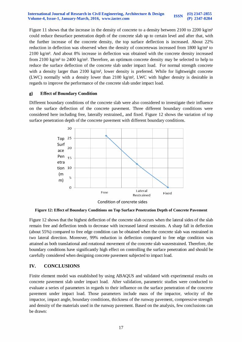
g) Effect of Boundary Condition
Different boundary conditions of the concrete slab were also considered to investigate their influence
on the surface deflection of the concrete pavement. Three different boundary conditions were
considered here including free, laterally restrained,, and fixed. Figure 12 shows the variation of top
surface penetration depth of the concrete pavement with different boundary conditions.
Figure 12: Effect of Boundary Conditions on Top Surface Penetration Depth of Concrete Pavement
Figure 12 shows that the highest deflection of the concrete slab occurs when the lateral sides of the slab
remain free and deflection tends to decrease with increased lateral restraints. A sharp fall in deflection
(about 55%) compared to free edge condition can be obtained when the concrete slab was restrained in
two lateral direction. Moreover, 99% reduction in deflection compared to free edge condition was
attained as both translational and rotational movement of the concrete slab wasrestrained. Therefore, the
boundary conditions have significantly high effect on controlling the surface penetration and should be
carefully considered when designing concrete pavement subjected to impact load.
IV. CONCLUSIONS
Finite element model was established by using ABAQUS and validated with experimental results on
concrete pavement slab under impact load. After validation, parametric studies were conducted to
evaluate a series of parameters in regards to their influence on the surface penetration of the concrete
pavement under impact load. Those parameters include mass of the impactor, velocity of the
impactor, impact angle, boundary conditions, thickness of the runway pavement, compressive strength
and density of the materials used in the runway pavement. Based on the analysis, few conclusions can
be drawn:
Condition of concrete sides
Top
Surf
ace
Pen
etra
tion
(m
m)
International Journal of Research in Civil Engineering, Architecture & Design
Volume-4, Issue-1, January-March, 2016, www.iaster.com ISSN
(O) 2347-2855
(P) 2347-8284
18
For both selected pavement, the impact velocity has significant influence on the surface
depression.
The effect of impact mass density on top surface depression of the advanced multi-layer
composite pavement is negligible whereas slight effects were found for the concrete
pavement.
The impact angle has significant influence on the deflection of top surface for both types of
runway pavement. In average, change of impact angle from 30 to 60 degrees causes an
increase in surface penetration of runway pavement of about 78% whereas an increase in
impact angle from 60 to 90 degrees results in a rise of surface penetration of about 42%.
The top surface penetration of concrete slab decreases with the increase of slab thickness of
runway pavement. In average, the surface penetration can be reduced by 1% with 1 mm
increase in slab thickness.
The increase in the compressive strength of concrete up to the normal strength concrete range
(30 MPa to 50 MPa) tends to increase the surface penetration moderately. Again, the
utilization of sufficient high strength concrete is found to be useful in reducing the surface
depression.
Moreover, selection of optimum density of concrete is helpful in reducing the surface
depression of concrete pavement.
Besides, the surface penetration of runway pavement can be reduced by restraining the sides
of concrete pavement.
REFERENCES
[1] M. Kim, and E. Tutumluer, Multiple Wheel Load Interaction in Flexible Pavements, Journal
of the Transportation Research Board, No. 2068, 2008, 9-60.
[2] K. Su, Y. Hachiya, and R. Maekawa, Study on Recycled Asphalt Concrete for Use in Surface
Course in Airport Pavement, Journal of Resources, Conservation And Recycling, 54, 2009,
37-44, Elsevier Science Limited.
[3] I.L. Al-Qadi, S. Portas, M. Coni, and S. Lahouar, Runway Instrumentation and Response
Measurements, Journal of the Transportation Research Board, No. 2153, 2010, 162-169.
[4] V. Khanna, M.A. Mooney, and G.A. Miller, Impulse Response Dynamic Stiffness Decay in
Aging General Aviation Airfield Pavements, Journal of the Transportation Research Board,
No. 2153, 2012, 162-169.
[5] K. Gopalakrishnan and M.R. Thompson, Behaviour of Airfield Pavement Subgrades Under Blast
Load Test. Proceedings of the institution of Civil Engineers, Transport 160, TR2, 2007, 79-87.
[6] H. Kim, and W.G. Buttler, Finite Element Cohesive Fracture Modelling of Airport Pavements
at Low Temperatures, Journal of Cold Regions Science and Technology, 57, 2009, 123-131,
Elsevier Science Limited.
[7] D. Rufino and J. Roesler, Effect of Slab-Base Interaction on Measured Concrete Pavement
Responses, ASCE Journal of Transportation Engineering, 132, 2006, 425-435.
[8] X. Yan,X. Weng, and Y. Kou, Influence of Fiber Grid on Interlayer Bond Property of Airport
Double-Layer Pavement, Journal of Reinforced Plastics and Composites, 33(1), 2014101-111.

International Journal of Research in Civil Engineering, Architecture & Design
Volume-4, Issue-1, January-March, 2016, www.iaster.com ISSN
(O) 2347-2855
(P) 2347-8284
19
[9] M.R. Taheri, M.M Zaman, and A. Alvappillai, Dynamic Response of Concrete Pavement to
Moving Aircrafts, Journal of Applied Math Modelling, 14, 1990, 562-575.
[10] K. Hoegh, L. Khazanovich, K. Maser, and N. Tran, Evaluation of Ultrasonic Technique for
Detecting Delamination in Asphalt Pavements, Journal of the Transportation Research
Board, 2316, 2012, 105-110.
[11] K.R. Maser, and I. Sande, Condition Assessment of Transportation Infrastructure Using
Ground-Penetrating Radar, Journal of Infrastructure Systems, 2(2), 1996, 94-101.
[12] A. Moropoulou, N.P. Avdelidis, M. Kouri, and K. Kakaras, An Application of Thermography
for Detection of Delamination in Airport Pavements, Journal of NDT and E International, 34,
2001, 329-335, Elsevier Science Limited.
[13] S. Kuo, H.S. Mahgoub, R.D. Holliday, Pavement Responses Due to Hard Landing of Heavy
Aircraft, Journal of the Transportation Research Board, 1896, 2004, 88-95.
[14] M. Bounsanti, and G. Leonardi,A Finite Element Model to Evaluate Airport Flexible Pavements
Response Under Impact, Journal of Applied Mechanics and Materials, 138, 2011, 257-262.
[15] W. Jun,Development of Advanced Pavement Materials System for Blast Laod, Thesis of
Doctor of Philosophy, National University of Singapore, 2012.
[16] Y. Fujita, and R. Ishimaru, Study on Internal Friction Angle and Tensile Strength of Plain
Concrete, Proc. on Fracture Mechanics of Concrete Structures, Germany, 1998, 325-334.
[17] J. Ozbolt, A. Sharma, B. Irhan, and E. Sola, Tensile Behaviour of Concrete Under High
Loading Rates, International Journal of Impact Engineering, 69, 2014, 55-68,Elsevier
Science Limited.
[18] I. Mijangos, and K.U. Kelly, Drucker-Prager Finite Element Constitutive Model of
Microindentation in Polycrystalline Alumina, Proc. of the SEM Annual Conference, June 1-4,
2009, Albuquerque New Mexico, USA, 2009.
[19] G.T. Houlsby, How the Dilatancy of Soils Affects their Behavior, Tenth European
Conference on Soil Mechanics and Foundation Engineering, 1991, Florence, Italy.
[20] V. Carvelli, C. Corazza, and C. Poggi, Mechanical Modelling of Monofilament Technical
Textiles. Journal of Computational Materials Science, 42, 2007, 679-691, Elsevier Science
Limited.