Embed Size (px)
Citation preview
Numerical Study on condensation Process of Steam Flow in Nozzles
A. S. Hegazy, W. A. El-Askary, A. A. El-Terhy and M. S. Farag
Mechanical Power Engineering Department - Faculty of Engineering Menoufiya University - Shebin El-kom-Egypt
Abstract
Steam ejector is an important component in engineering applications, which require high vacuum, such as steam plant condenser. Prediction of steam ejector performance is very significant tool for the design of the ejector. The steam ejector consists of three parts; nozzle, mixing chamber and diffuser. The nozzle has the task of creating the vacuum required. In the current paper numerical treatment of wet steam flow through the nozzle of an ejector is presented. The first task of this work is to test and evaluate several turbulence models on a generic case, constructed for turbulent steam flow in a convergent-divergent nozzle. The effect of pressure ratios, that is responsible for controlling the location or absence of the generated shock wave as well as the impact of the shock wave on the condensation of steam inside the nozzle are numerically concerned. These features are clearly observed from the pressure distribution, Mach number, liquid mass fraction, droplet nucleation rate, droplet critical radius and static temperature. It is concluded from the current work that the standard k-ω model is the most appropriate turbulence model for simulating this complex flow compared to the other considered models for nozzle steam flow sumulation.
Keywords: CFD; Nozzle; Wet steam model; Turbulence Models; Shock Wave and Two Phase Flow (Steam condensing).
1 - INTRODUCTION
Nozzles are the main parts in many industrial applications, such as jet pump and ejector. Supersonic flow in a convergent–divergent nozzle is a fundamental fluid phenomenon that affects a large variety of applications. When a supersonic nozzle is operated at suitable pressure ratios well below its design point, a shock wave forms inside the nozzle and flow downstream of the shock separates from the nozzle walls. Even though flow separation is typically viewed as an undesirable occurrence, it may have some interesting applications in the area of fluid mixing. During the rapid expansion of steam, a condensation process will take place shortly after the state path crosses the vapor-saturation line. The expansion process causes the super-heated dry steam to first subcool and then nucleates to form a two-phase mixture of saturated vapor and fine liquid droplets known as wet steam. Modeling wet steam is very important in the analysis and design of steam nozzles. An increase in wetness fraction at nozzle exit is gained by decreasing exit pressure. This leads to a reduction in aerodynamic efficiency of the nozzle operating in the wet steam region.
Recent Advances on Mechanics, Materials, Mechanical Engineering and Chemical Engineering
ISBN: 978-1-61804-295-8 239
Avetissian et al. [1] noticed that the standard k–ε turbulence model can be invalid for predicting two-phase flows in transonic nozzles. The influence of inlet moisture on spontaneously condensing flow resembles the effect of turbulence. Pressure based Eulerian–Eulerian multi-phase models for non-equilibrium condensation in transonic steam flow were studied by Gerber and Kermani [2]. The equations were applied to predict the moisture distribution in low and high pressure steam flow in a Laval nozzle. Numerical analyses of spontaneously condensing phenomena in nozzle of steam-jet vacuum pump were introduced by Wang et al. [3]. The condensation heat produced during wet steam condensation in the nozzle increases the pressure and decreases the velocity at the outlet of the nozzle which would depress pumping performance of steam-jet pump and the supersonic steam condensation in the nozzle may be avoided or weakened by enhancing steam superheat degree. Numerical modelling of steam condensing flow in low and high-pressure nozzles were considered by Dykas and Wróblewski [4]. The implemented condensation model predicted the condensation onset correctly both for low and high pressures. The applied droplet growth model was found to be strongly dependent on the value of Knudsen numbers, which differs significantly for the low and high pressure values used. Yang and Shen [5] distinguished the numerical simulation on non-equilibrium spontaneous condensation in supersonic steam flow. Different from the isentropic expansion, in supersonic steam flow non-equilibrium spontaneous condensation will occur in the form of “condensation shock” downstream of the nozzle throat at a certain value.
Single- and two-fluid models for steam condensing flow modeling were introduced by Dykas and Wróblewski [6]. Cinar et al. [7] studied the nucleation of steam during expansion through a nozzle. The initial centers of nucleation, which have sufficient time to grow at relatively small values of expansion rate, affect the subsequent history of the flow; the effect of pressure ratio is important in the case of low expansion rate. Viscous and unsteady flow calculations of condensing steam in nozzles were studied by Simpson and White [8]. Viscous calculations for steady flow indicate that growth of the boundary layer has a significant impact on the predicted pressure distributions and droplet sizes, at least for cases where two-dimensional effects are prominent.
In the present study, different turbulence models are considered to simulate the steam flow in convergent–divergent nozzle. These turbulence models are standard ε−k model, Realizable
ε−k model, RNG ε−k model, standard ω−k model and SST ω−k model. The main aim of the study is to prediction of flow characteristic of wet steam and to validate the results obtained from simulation against experimental data available in literature. Also, selection of the most appropriate turbulence model that can handle steam flow through nozzle is discussed, and extended for further simulation handling different effects on nozzle performance. 2 - MATHEMATICAL MODEL
The mathematical model of homogeneous condensation in wet steam flow is based on the physical model, which was executed by the general CFD Code FLUENT 6.3 [9]. This is namely thermodynamic non-equilibrium process, which can take place during the expansion of steam flow. This state is characterized by subcooling of steam, when the steam
Recent Advances on Mechanics, Materials, Mechanical Engineering and Chemical Engineering
ISBN: 978-1-61804-295-8 240
temperature is lower than the equilibrium temperature of saturated steam for the given pressure. The wet steam is a mixture of two phases, the primary phase is the gaseous - phase consisting of water vapor while the secondary phase is the liquid-phase composed of condensed water droplets. To simplify the present analyses, the following assumptions have been made : No slip velocity between the droplets and vapor surrounding them, the interactions between droplets are neglected, the wetness mass fraction is small, (less than 20%) ; 2-D; turbulent steady flow; adiabatic nozzle walls and viscous compressible flow.
This section presents the governing equations, which describe the ideal flow behavior through the nozzle. Based on the above mentioned assumptions, the governing equations of steam flow and energy exchange through supersonic nozzle have been developed. Figure 1 shows cross section through the nozzle to be studied. Equation of state The steam equation of state used in the solver, which relates the pressure to the vapor density and temperature, is given by [10]:
)1( 2vvv CBRTP ρρρ ++= (1)
Where B (m3 /kg) and C (m6 /kg2) are coefficients. The mixture density ( ρ ) can be related to the vapor density ( vρ ) by the following equation:
)1( βρρ−
= v (2)
Where β is Wetness mass fraction and is defined as: tot
l
mm
=β
Equation of Continuity 0. =∇+ V
DtD
ρρ (3)
Equation of Motion r - Component
−∂∂
+
∂∂
+∂∂
∂∂
+
∇−
∂∂
∂∂
+∂∂
−=
rv
rv
rrv
zv
zV
rv
rrp
DtDv rrzrrr µµµρ 2.
322
(4)
z - Component
∂∂
+∂∂
∂∂
+
∇−
∂∂
∂∂
+∂∂
−=rv
zvr
rrV
zv
zzp
DtDv zrzz µµρ 1.
322
(5)
Equation of energy φρ +
∂∂
∂∂
+
∂∂
+∂∂
+=zTk
zrTkr
rtQ
DtDpTC
DtD
P1)( (6)
Where
zv
rv
DtD
zr ∂∂
+∂∂
≡ (7)
zv
rrv
rV zr
∂∂
+∂∂
=∇1.
(8)
Recent Advances on Mechanics, Materials, Mechanical Engineering and Chemical Engineering
ISBN: 978-1-61804-295-8 241
∇−
∂∂
+∂∂
+
∂∂
+
∂+
∂∂
= 22222
).(322 V
rv
zv
zv
rv
rv zrzrr
µφ (9)
Where µ represents the effective viscosity in which tl µµµ += , the laminar viscosity ( lµ ) depends on the fluid pressure and temperature and tµ is the turbulent viscosity that can be computed using the turbulence model. For wet steam model, two additional transport equations are needed [11]. The first transport equation governs the mass fraction of the condensed liquid phase ( β ):
Γ=∇+∂
∂ ).()( Vt
βρβρ (10)
Where Γ is the mass generation rate due to condensation and evaporation (kg per unit volume per second). The second transport equation models the evolution of the number density of the droplets per unit volume (η ):
IVt
ρηρρη
=∇+∂
∂ ).()(
(11)
The mass generation rate due to condensation and evaporation (Γ ), which is correlated with nucleation rate I (number of new droplets per unit volume per second) and growth/demise of these droplets [11]. Therefore, Γ is written as:
trrrI ll ∂∂
+=Γ ∗23 4
34 ηρπρπ (12)
Where ∗r is the Kelvin-Helmholtz critical droplet radius, above which the droplet will grow and evaporate. An expression for ∗r is given by [12].
STRr
l ln2
ρσ
=∗ (13)
The condensation process involves two mechanisms, the transfer of mass from the vapor to the droplets and the transfer of heat from the droplets to the vapor in the form of latent heat. This energy transfer rate relation was presented in [13] and can be written as:
)(2
12
TTCRT
ptQ
trh sPllv −
+=
∂∂
=∂∂
γγ
πρ (14)
Rearranging the terms in equation (14) we get
)(2
12
TTCRTh
ptr
sPllv
−+
=∂∂
γγ
πρ (15)
Where sT is the saturation temperature.
In the model, the classical homogeneous nucleation theory describes the formation of a liquid-phase in the form of droplets from a saturated phase in the absence of impurities or foreign particles, and the nucleation rate is given by:
Recent Advances on Mechanics, Materials, Mechanical Engineering and Chemical Engineering
ISBN: 978-1-61804-295-8 242
− ∗
+= TK
r
ml
vc beM
qI 34
3
22
2)1(
σπ
πσ
ρρ
θ (16)
Where cq is the evaporation coefficient, bK is the Boltzmann constant, mM is mass of one
molecule. The nonisothermal correction factor, θ, is given by [12]:
−
+−
= 5.0)1()1(2
RTh
RTh lvlv
γγθ (17)
Where )( lvlv hhh −= is the specific enthalpy of evaporation at pressure p and γ is the ratio
of specific heat capacities. The mixture properties are calculated using the following mixing relation:
vlm φβφβφ )1( −+= (18)
where: φ represents any of the following thermodynamic properties: tVP KandCCsh µ,,,, .
3 - COMPUTATIONAL METHOD The finite volume solver, FLUENT 6.3, is used to perform the numerical solution of the two-
dimensional compressible Reynolds Averaged Navier–Stokes (RANS) equations in connection with different turbulence models including standard ε−k , RNG ε−k , Realizable ε−k , standard
ω−k and SST ω−k turbulence models. 3-1 Computational Domain and Mesh Definition
The details of the full 2D computational domain and geometry are presented in Fig. 1. The chosen grid represents a compromise between the accuracy and computer time [14] of steam nozzle simulation. The computational mesh generated is )( ji× = )10170( × , where i the number of points in the streamwise direction and j is the number of points in the direction normal to the axis. 3-2 Boundary Conditions
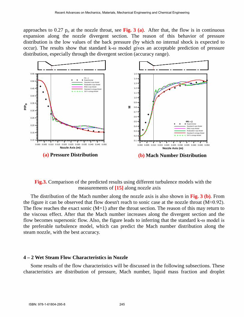
The 2-D computational domain with the assigned boundary conditions is shown in Fig. 2. The saturation properties (temperature and pressure), are considered at the flow inlet. The outlet pressure boundary condition must be identified.
Recent Advances on Mechanics, Materials, Mechanical Engineering and Chemical Engineering
ISBN: 978-1-61804-295-8 243
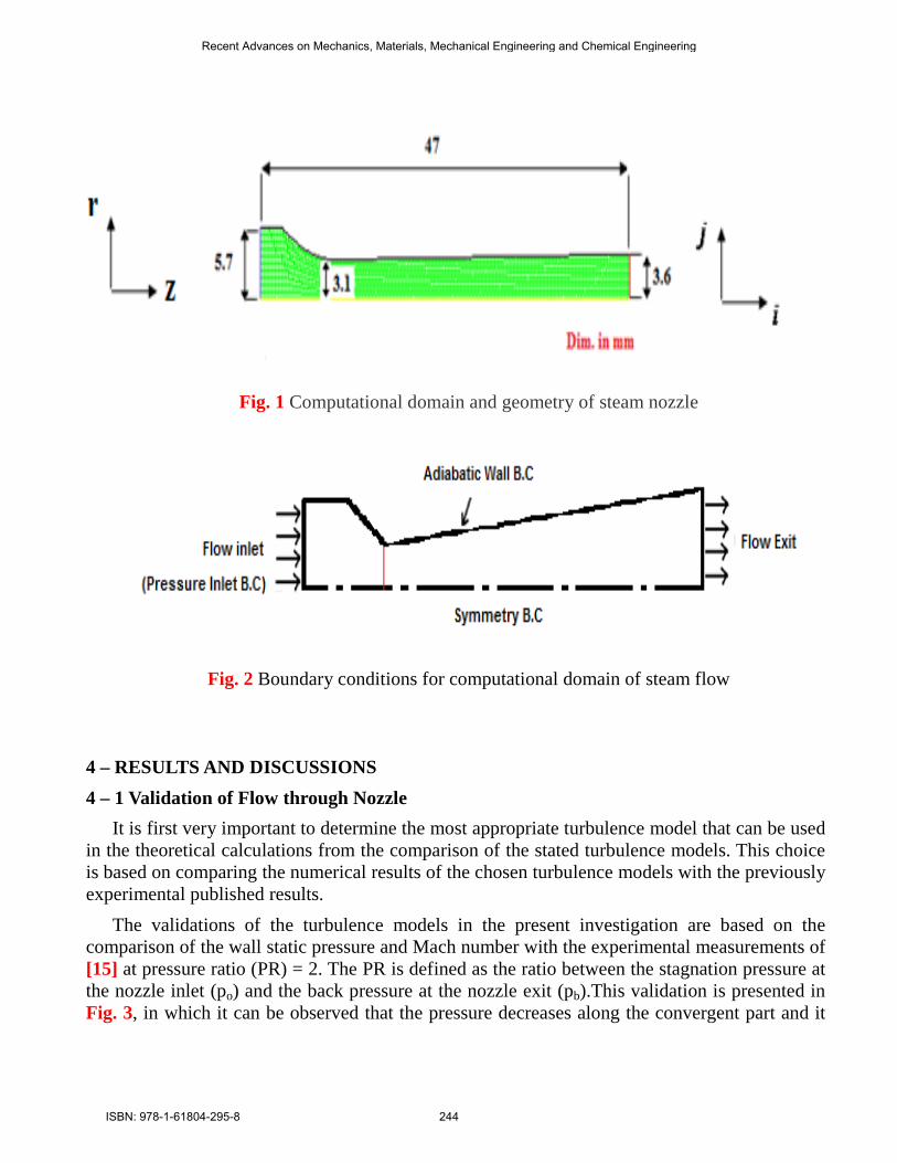
Fig. 1 Computational domain and geometry of steam nozzle
Fig. 2 Boundary conditions for computational domain of steam flow
4 – RESULTS AND DISCUSSIONS 4 – 1 Validation of Flow through Nozzle
It is first very important to determine the most appropriate turbulence model that can be used in the theoretical calculations from the comparison of the stated turbulence models. This choice is based on comparing the numerical results of the chosen turbulence models with the previously experimental published results.
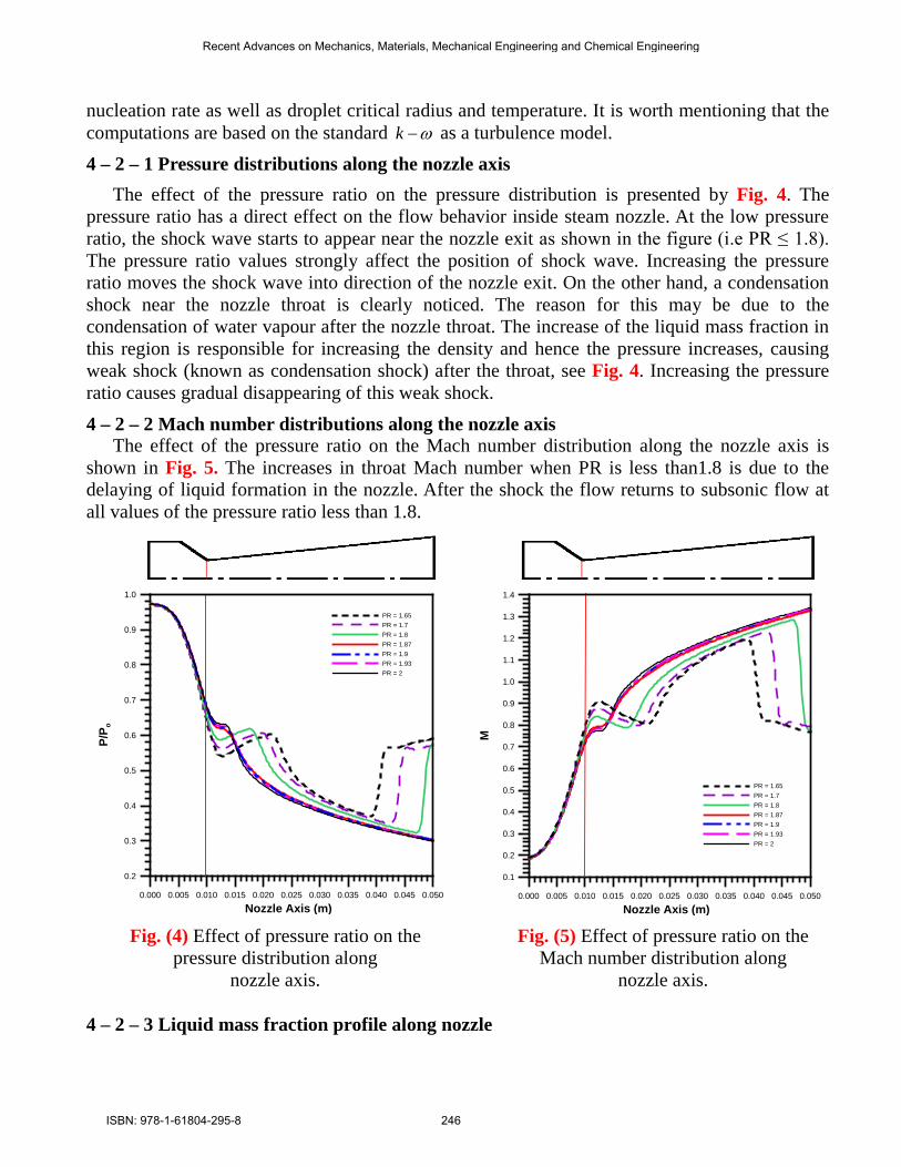
The validations of the turbulence models in the present investigation are based on the comparison of the wall static pressure and Mach number with the experimental measurements of [15] at pressure ratio (PR) = 2. The PR is defined as the ratio between the stagnation pressure at the nozzle inlet (po) and the back pressure at the nozzle exit (pb).This validation is presented in Fig. 3, in which it can be observed that the pressure decreases along the convergent part and it
Recent Advances on Mechanics, Materials, Mechanical Engineering and Chemical Engineering
ISBN: 978-1-61804-295-8 244
approaches to 0.27 po at the nozzle throat, see Fig. 3 (a). After that, the flow is in continuous expansion along the nozzle divergent section. The reason of this behavior of pressure distribution is the low values of the back pressure (by which no internal shock is expected to occur). The results show that standard k-ω model gives an acceptable prediction of pressure distribution, especially through the divergent section (accuracy range).
0.000 0.005 0.010 0.015 0.020 0.025 0.030 0.035 0.040 0.045 0.050
Nozzle Axis (m)
0.10
0.15
0.20
0.25
0.30
0.35
0.40
0.45
0.50
0.55
P/P o
PR = 2ExperimentalStandard k-eps ModelRealizable k-eps ModelRNG k-eps ModelStandard k-omega ModelSST k-omega Model
(a) Pressure Distribution
0.000 0.005 0.010 0.015 0.020 0.025 0.030 0.035 0.040 0.045 0.050
Nozzle Axis (m)
0.1
0.2
0.3
0.4
0.5
0.6
0.7
0.8
0.9
1.0
1.1
1.2
1.3
1.4
1.5
M
PR = 2Experimental Standard k-eps ModelRNG k-eps ModelRealizable k-eps ModelStandard k-omega ModelSST k-omega Model
(b) Mach Number Distribution
Fig.3. Comparison of the predicted results using different turbulence models with the measurements of [15] along nozzle axis
The distribution of the Mach number along the nozzle axis is also shown in Fig. 3 (b). From the figure it can be observed that flow doesn't reach to sonic case at the nozzle throat (M≈0.92). The flow reaches the exact sonic (M=1) after the throat section. The reason of this may return to the viscous effect. After that the Mach number increases along the divergent section and the flow becomes supersonic flow. Also, the figure leads to inferring that the standard k-ω model is the preferable turbulence model, which can predict the Mach number distribution along the steam nozzle, with the best accuracy.
4 – 2 Wet Steam Flow Characteristics in Nozzle Some results of the flow characteristics will be discussed in the following subsections. These
characteristics are distribution of pressure, Mach number, liquid mass fraction and droplet
Recent Advances on Mechanics, Materials, Mechanical Engineering and Chemical Engineering
ISBN: 978-1-61804-295-8 245
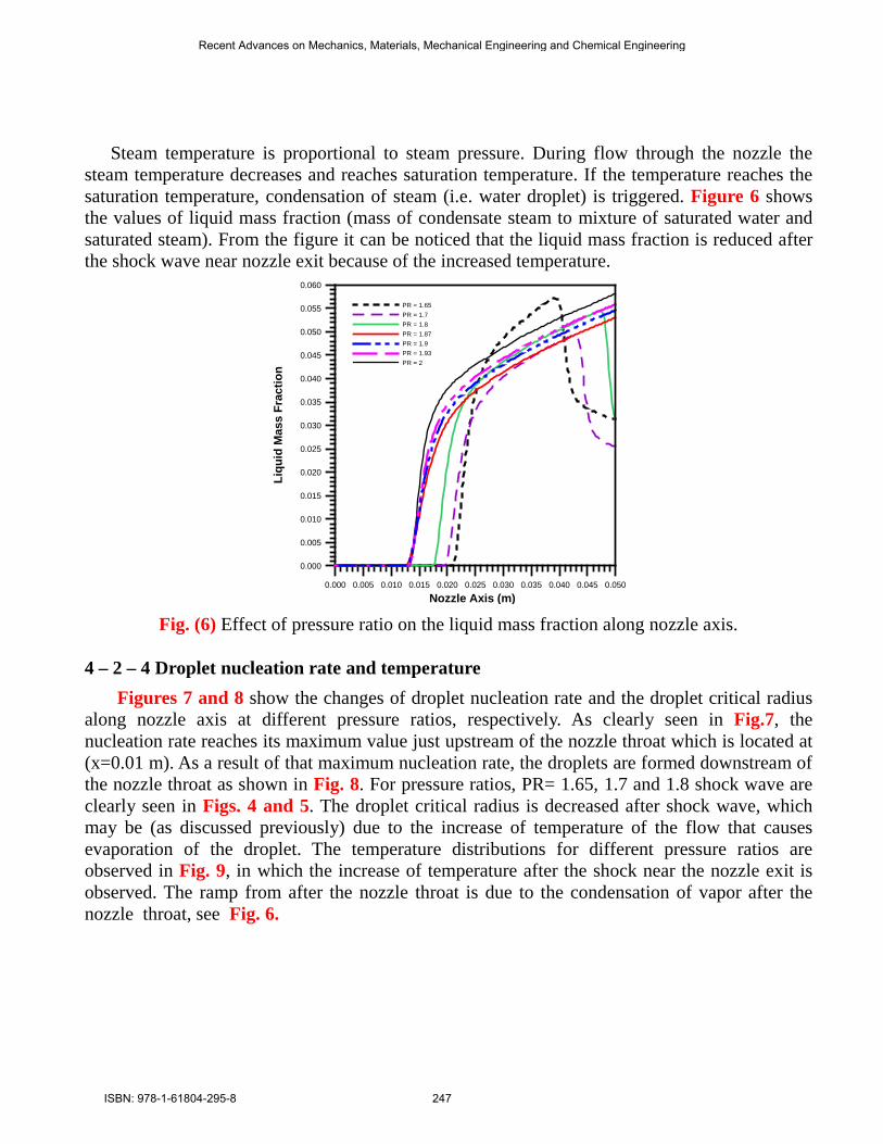
nucleation rate as well as droplet critical radius and temperature. It is worth mentioning that the computations are based on the standard ω−k as a turbulence model. 4 – 2 – 1 Pressure distributions along the nozzle axis
The effect of the pressure ratio on the pressure distribution is presented by Fig. 4. The pressure ratio has a direct effect on the flow behavior inside steam nozzle. At the low pressure ratio, the shock wave starts to appear near the nozzle exit as shown in the figure (i.e PR ≤ 1.8). The pressure ratio values strongly affect the position of shock wave. Increasing the pressure ratio moves the shock wave into direction of the nozzle exit. On the other hand, a condensation shock near the nozzle throat is clearly noticed. The reason for this may be due to the condensation of water vapour after the nozzle throat. The increase of the liquid mass fraction in this region is responsible for increasing the density and hence the pressure increases, causing weak shock (known as condensation shock) after the throat, see Fig. 4. Increasing the pressure ratio causes gradual disappearing of this weak shock.
4 – 2 – 2 Mach number distributions along the nozzle axis The effect of the pressure ratio on the Mach number distribution along the nozzle axis is
shown in Fig. 5. The increases in throat Mach number when PR is less than1.8 is due to the delaying of liquid formation in the nozzle. After the shock the flow returns to subsonic flow at all values of the pressure ratio less than 1.8.
0.000 0.005 0.010 0.015 0.020 0.025 0.030 0.035 0.040 0.045 0.050
Nozzle Axis (m)
0.2
0.3
0.4
0.5
0.6
0.7
0.8
0.9
1.0
P/P o
PR = 1.65PR = 1.7PR = 1.8PR = 1.87PR = 1.9PR = 1.93PR = 2
0.000 0.005 0.010 0.015 0.020 0.025 0.030 0.035 0.040 0.045 0.050
Nozzle Axis (m)
0.1
0.2
0.3
0.4
0.5
0.6
0.7
0.8
0.9
1.0
1.1
1.2
1.3
1.4
M
PR = 1.65PR = 1.7PR = 1.8PR = 1.87PR = 1.9PR = 1.93PR = 2
Fig. (4) Effect of pressure ratio on the pressure distribution along
nozzle axis.
Fig. (5) Effect of pressure ratio on the Mach number distribution along
nozzle axis.
4 – 2 – 3 Liquid mass fraction profile along nozzle
Recent Advances on Mechanics, Materials, Mechanical Engineering and Chemical Engineering
ISBN: 978-1-61804-295-8 246
Steam temperature is proportional to steam pressure. During flow through the nozzle the steam temperature decreases and reaches saturation temperature. If the temperature reaches the saturation temperature, condensation of steam (i.e. water droplet) is triggered. Figure 6 shows the values of liquid mass fraction (mass of condensate steam to mixture of saturated water and saturated steam). From the figure it can be noticed that the liquid mass fraction is reduced after the shock wave near nozzle exit because of the increased temperature.
0.000 0.005 0.010 0.015 0.020 0.025 0.030 0.035 0.040 0.045 0.050
Nozzle Axis (m)
0.000
0.005
0.010
0.015
0.020
0.025
0.030
0.035
0.040
0.045
0.050
0.055
0.060Li
quid
Mas
s Fr
actio
n
PR = 1.65PR = 1.7PR = 1.8PR = 1.87PR = 1.9PR = 1.93PR = 2
Fig. (6) Effect of pressure ratio on the liquid mass fraction along nozzle axis.
4 – 2 – 4 Droplet nucleation rate and temperature
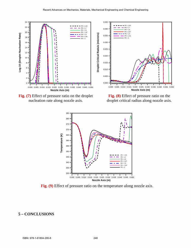
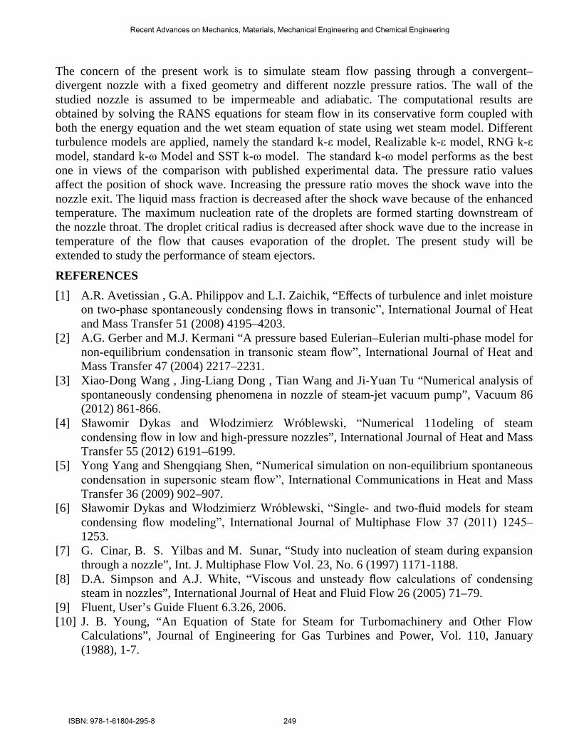
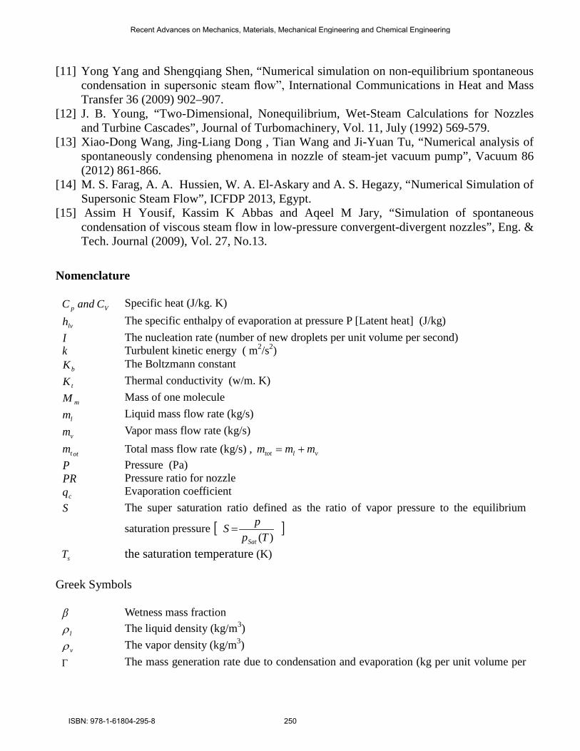
Figures 7 and 8 show the changes of droplet nucleation rate and the droplet critical radius along nozzle axis at different pressure ratios, respectively. As clearly seen in Fig.7, the nucleation rate reaches its maximum value just upstream of the nozzle throat which is located at (x=0.01 m). As a result of that maximum nucleation rate, the droplets are formed downstream of the nozzle throat as shown in Fig. 8. For pressure ratios, PR= 1.65, 1.7 and 1.8 shock wave are clearly seen in Figs. 4 and 5. The droplet critical radius is decreased after shock wave, which may be (as discussed previously) due to the increase of temperature of the flow that causes evaporation of the droplet. The temperature distributions for different pressure ratios are observed in Fig. 9, in which the increase of temperature after the shock near the nozzle exit is observed. The ramp from after the nozzle throat is due to the condensation of vapor after the nozzle throat, see Fig. 6.
Recent Advances on Mechanics, Materials, Mechanical Engineering and Chemical Engineering
ISBN: 978-1-61804-295-8 247
0.000 0.005 0.010 0.015 0.020 0.025 0.030 0.035 0.040 0.045 0.050
Nozzle Axis (m)
0
2
4
6
8
10
12
14
16
18
20
22
24Lo
g 10
(Dro
plet
Nuc
leat
ion
Rat
e)
PR = 1.65PR = 1.7PR = 1.8PR = 1.87PR = 1.9PR = 1.93PR = 2
0.000 0.005 0.010 0.015 0.020 0.025 0.030 0.035 0.040 0.045 0.050
Nozzle Axis (m)
0.000
0.005
0.010
0.015
0.020
0.025
0.030
0.035
0.040
0.045
Dro
plet
Crit
ical
Rad
uis
(mic
rons
)
PR = 1.65PR = 1.7PR = 1.8PR = 1.87PR = 1.9PR = 1.93PR = 2
Fig. (7) Effect of pressure ratio on the droplet
nucleation rate along nozzle axis. Fig. (8) Effect of pressure ratio on the
droplet critical radius along nozzle axis.
0.000 0.005 0.010 0.015 0.020 0.025 0.030 0.035 0.040 0.045 0.050
Nozzle Axis (m)
330
335
340
345
350
355
360
365
370
375
380
385
Tem
pera
ture
(K)
PR = 1.65PR = 1.7PR = 1.8PR = 1.87PR = 1.9PR = 1.93PR = 2
Fig. (9) Effect of pressure ratio on the temperature along nozzle axis.
5 – CONCLUSIONS
Recent Advances on Mechanics, Materials, Mechanical Engineering and Chemical Engineering
ISBN: 978-1-61804-295-8 248
The concern of the present work is to simulate steam flow passing through a convergent–divergent nozzle with a fixed geometry and different nozzle pressure ratios. The wall of the studied nozzle is assumed to be impermeable and adiabatic. The computational results are obtained by solving the RANS equations for steam flow in its conservative form coupled with both the energy equation and the wet steam equation of state using wet steam model. Different turbulence models are applied, namely the standard k-ε model, Realizable k-ε model, RNG k-ε model, standard k-ω Model and SST k-ω model. The standard k-ω model performs as the best one in views of the comparison with published experimental data. The pressure ratio values affect the position of shock wave. Increasing the pressure ratio moves the shock wave into the nozzle exit. The liquid mass fraction is decreased after the shock wave because of the enhanced temperature. The maximum nucleation rate of the droplets are formed starting downstream of the nozzle throat. The droplet critical radius is decreased after shock wave due to the increase in temperature of the flow that causes evaporation of the droplet. The present study will be extended to study the performance of steam ejectors.
REFERENCES [1] A.R. Avetissian , G.A. Philippov and L.I. Zaichik, “Effects of turbulence and inlet moisture
on two-phase spontaneously condensing flows in transonic”, International Journal of Heat and Mass Transfer 51 (2008) 4195–4203.
[2] A.G. Gerber and M.J. Kermani “A pressure based Eulerian–Eulerian multi-phase model for non-equilibrium condensation in transonic steam flow”, International Journal of Heat and Mass Transfer 47 (2004) 2217–2231.
[3] Xiao-Dong Wang , Jing-Liang Dong , Tian Wang and Ji-Yuan Tu “Numerical analysis of spontaneously condensing phenomena in nozzle of steam-jet vacuum pump”, Vacuum 86 (2012) 861-866.
[4] Sławomir Dykas and Włodzimierz Wróblewski, “Numerical 11odeling of steam condensing flow in low and high-pressure nozzles”, International Journal of Heat and Mass Transfer 55 (2012) 6191–6199.
[5] Yong Yang and Shengqiang Shen, “Numerical simulation on non-equilibrium spontaneous condensation in supersonic steam flow”, International Communications in Heat and Mass Transfer 36 (2009) 902–907.
[6] Sławomir Dykas and Włodzimierz Wróblewski, “Single- and two-fluid models for steam condensing flow modeling”, International Journal of Multiphase Flow 37 (2011) 1245–1253.
[7] G. Cinar, B. S. Yilbas and M. Sunar, “Study into nucleation of steam during expansion through a nozzle”, Int. J. Multiphase Flow Vol. 23, No. 6 (1997) 1171-1188.
[8] D.A. Simpson and A.J. White, “Viscous and unsteady flow calculations of condensing steam in nozzles”, International Journal of Heat and Fluid Flow 26 (2005) 71–79.
[9] Fluent, User’s Guide Fluent 6.3.26, 2006. [10] J. B. Young, “An Equation of State for Steam for Turbomachinery and Other Flow
Calculations”, Journal of Engineering for Gas Turbines and Power, Vol. 110, January (1988), 1-7.
Recent Advances on Mechanics, Materials, Mechanical Engineering and Chemical Engineering
ISBN: 978-1-61804-295-8 249
[11] Yong Yang and Shengqiang Shen, “Numerical simulation on non-equilibrium spontaneous condensation in supersonic steam flow”, International Communications in Heat and Mass Transfer 36 (2009) 902–907.
[12] J. B. Young, “Two-Dimensional, Nonequilibrium, Wet-Steam Calculations for Nozzles and Turbine Cascades”, Journal of Turbomachinery, Vol. 11, July (1992) 569-579.
[13] Xiao-Dong Wang, Jing-Liang Dong , Tian Wang and Ji-Yuan Tu, “Numerical analysis of spontaneously condensing phenomena in nozzle of steam-jet vacuum pump”, Vacuum 86 (2012) 861-866.
[14] M. S. Farag, A. A. Hussien, W. A. El-Askary and A. S. Hegazy, “Numerical Simulation of Supersonic Steam Flow”, ICFDP 2013, Egypt.
[15] Assim H Yousif, Kassim K Abbas and Aqeel M Jary, “Simulation of spontaneous condensation of viscous steam flow in low-pressure convergent-divergent nozzles”, Eng. & Tech. Journal (2009), Vol. 27, No.13.
Nomenclature
Vp CandC Specific heat (J/kg. K)
lvh The specific enthalpy of evaporation at pressure P [Latent heat] (J/kg) I The nucleation rate (number of new droplets per unit volume per second) k Turbulent kinetic energy ( m2/s2)
bK The Boltzmann constant
tK Thermal conductivity (w/m. K)
mM Mass of one molecule
lm Liquid mass flow rate (kg/s)
vm Vapor mass flow rate (kg/s)
ottm Total mass flow rate (kg/s) , vltot mmm += P Pressure (Pa) PR Pressure ratio for nozzle
cq Evaporation coefficient S The super saturation ratio defined as the ratio of vapor pressure to the equilibrium
saturation pressure [ ])(Tp
pSSat
=
sT the saturation temperature (K) Greek Symbols β Wetness mass fraction
lρ The liquid density (kg/m3)
vρ The vapor density (kg/m3) Γ The mass generation rate due to condensation and evaporation (kg per unit volume per
Recent Advances on Mechanics, Materials, Mechanical Engineering and Chemical Engineering
ISBN: 978-1-61804-295-8 250
second) η The number of liquid droplets per unit volume ∗r The Kelvin-Helmholtz critical droplet radius (m)
r The average radius of the droplet (m) γ The ratio of specificc heat capacities µ The dynamic viscosity (N.s/ m2) σ the liquid surface tension
kεω = Specific turbulent dissipation rate (1/s) ε Turbulent dissipation rate (m2/s3)
Abbreviations RNG The renormalization group SFM Single fluid model SST The shear stress transport TFM Two fluid model
Recent Advances on Mechanics, Materials, Mechanical Engineering and Chemical Engineering
ISBN: 978-1-61804-295-8 251