Embed Size (px)
Citation preview
PHYSICS OF FLUIDS VOLUME 14, NUMBER 5 MAY 2002
Numerical studies of a three-dimensional flow in suddenlycontracted channels
T. P. Chiang and Tony W. H. Sheua)
Department of Engineering Science and Ocean Engineering, National Taiwan University,Taipei, Taiwan, Republic of China
Robert R. HwangInstitute of Physics, Academia Sinica, Taipei, Taiwan, Republic of China
~Received 22 October 2001; accepted 18 January 2002; published 19 March 2002!
This paper aims to provide deeper insight into the suddenly contracted channel flow. The channelsunder investigation have a width of 18D, whereD represents the channel height upstream of thestep plane, and two contraction ratios:C52 and 4. In the present three-dimensional finite volumeanalysis, the advective fluxes are discretized using an upwind scheme that provides a third-orderaccurate solution in uniform grid cases. For efficient calculation of field variables, workingequations are solved separately based on the semi-implicit velocity-pressure coupling procedures.We exploit a theoretically appealing topological theory to determine lines of separation andreattachment, from which the pitchfork bifurcation flow can be identified in the contraction channel.To further elucidate the vortical details of the channel flow, we trace massless particles seeded in theflow, showing the spanwise spiraling flow motion. Emphasis is placed on flow phenomena in theupstream salient corner eddy and downstream tip corner eddy. ©2002 American Institute ofPhysics. @DOI: 10.1063/1.1459719#
wnihieheancolls
-es
izatio
aro
th
The
naledate
ra-toex-taler
the
ndion,
as
lowex-lineionbe-sureab-ich
m-nar
86il:
I. INTRODUCTION
There are many cases in which flow phenomenon dostream of a suddenly contracted channel is important, wthe non-Newtonian flow case being of particular interest. Tpractical importance in the polymer processing industr~Crochetet al.1! has prompted extensive investigations. Tflow geometry we consider in this simulation is that ofidealized suddenly contracted channel. The step plane issidered to be normal to the direction of the channel waThis flow has been investigated experimentally~see, for ex-ample, Durstet al.2!. Numerical investigations into the problem of present interest have been quite plentiful. Howevthey were mostly conducted on a two-dimensional ba~Dennis and Smith,3 Hunt,4 Hawken et al.,5 Huang andSeymour,6 and Chiang and Sheu7!.
Separation in a contraction channel can be characterby the recirculation eddies at the upstream salient cornerdownstream tip corner as shown in Fig. 1. The separalength L1 and the reattachment lengthL2 of the upstreamsalient corner eddy were reported to decrease in their mnitudes as the Reynolds number Re is increased fzero.2–7 These values become increasing whenRe.100~Ref. 6!. As Re.1000, L1 follows the asymptotic formulaL15(0.1289* ln(Re/2)20.5365)/2 for the channel withcontraction ratioC52 ~Ref. 3!. Hawken et al.5 revealedthat the downstream tip corner eddy becomes visible inrange of 300,Re,500 and 200,Re,300 forC52, and 4,
a!Author to whom correspondence should be addressed. Telephone: 823625470 ext. 246; fax: 886-2-23661703; electronic [email protected]
1601070-6631/2002/14(5)/1601/16/$19.00
-thes
n-.
r,is
edndn
g-m
e
respectively, and, becomes larger as Re increases.reattachment lengthL3 varies linearly with the Reynoldsnumber Re according toL35a* Re2b, where ~a, b! areestimated to be (0.336431023,0.1088) and (0.401131023,0.0565) for C52 (500<Re<4000) and 4 (300<Re<2000), respectively.7
Considering the rapidly increasing use of computatiofluid dynamics code to model flow behavior, we performin this study a three-dimensional simulation to investigthe effects of the Reynolds numbers and the contractiontios on the contraction channel flow. As a first attemptstudy this problem, we considered a channel used in anperimental work so as to reproduce experimenmeasurements2 and, thus, validate the analysis code. Anothaim was to provide further details about the nature offlow that was difficult to obtain in the experiment.
When considering the flow downstream of a planar asymmetric channel expansion, a larger re-circulating regwhich appeared preferentially at one wall of the channel, wexperimentally observed by Cherdronet al.8 and Sobey.9
Above the critical Reynolds number,Rec , the flow patternbecomes substantially different from that observed bethis value. Under these circumstances, the suddenlypanded flow can no longer be symmetric about the centerof the channel, and a process known as pitchfork bifurcatcan occur. This causes momentum transfer to proceedtween the fluid shear layers and can, in turn, cause a presof nonuniform type to form across the channel. This estlished pressure gradient leads to an asymmetric flow, whwe refer to as the Coanda effect~Wille and Fernolz10!. In-vestigations into the flow asymmetry in a geometrically symetric channel have mostly focused on flow through pla
-2-
1 © 2002 American Institute of Physics
s
on
-lfo
ull
onaono
reth
aow
c-eg-ib-ionent
fiveowreti-e-d
d. Wein-VI
assiblen-n-os-thetor
vethe
the
coco
1602 Phys. Fluids, Vol. 14, No. 5, May 2002 Chiang, Sheu, and Hwang
symmetric channel expansions. One can refer to the workFearnet al.,11 Drikakis,12 Battagliaet al.,13 Alleborn et al.,14
Rusak and Hawa,15 Mizushima and Shiotani,16 and Hawaand Rusak,17,18 which provided clear insight into the flowdynamics near the critical Reynolds number and demstrated the existence of a bifurcation phenomenon.
Previous numerical studies2–6 have conducted the twodimensional contraction flow analyses only in the hachannel. The present authors presented the critical Reynnumbers as 3075 and 1355 in their two-dimensional fchannel calculations forC52 and 4, respectively.7 To thebest of authors’ knowledge, no investigation has been cducted to study the bifurcation flow in the three-dimensiosudden contraction channel. The present three-dimensistudy takes the channel span into consideration. One ofmain aims is to determine whether pitchfork bifurcationmains a main signature of the three-dimensional flow incontraction channel.
The remaining sections of this paper are organizedfollows. In Sec. II, we present equations that govern the fl
FIG. 1. Schematic of the three-dimensional channel, with a suddenlytracted plane atx50. Both separated–reattached lengths and boundaryditions are provided.
of
-
-lds-
n-lal
ur-e
s
motion in the channel. This is followed by a brief introdution to the finite volume discretization method and the sregated solution algorithm. Section IV is devoted to descring first the investigated problem and, then, the validatstudy of the employed analysis code. In Sec. V, we presnumerical results obtained at two contraction ratios andReynolds numbers. To broaden our understanding of the flseparation–reattachment in the channel, we adopt a theocally rigorous topological theory. We show that thredimensional pitchfork bifurcation is physically relevant ancan be suppressed as the channel aspect ratio is reducealso study in detail the spanwise spiraling flow structureside the salient and tip eddies. Finally, we provide in Sec.concluding remarks.
II. MATHEMATICAL MODEL
In the present investigation, the numerical technique wused to simulate the three-dimensional steady incompresand viscous flow of a non-conducting fluid through a cotraction channel schematically shown in Fig. 1. The Newtoian fluid under investigation has a constant dynamic viscity. The governing equations that can describecontraction channel flow motion are expressed in vecform as
uI •¹uI 52¹p11
Re¹2uI , ~1!
¹•uI 50. ~2!
In the above primitive-variable equations,u, v, andw are thevelocity components in thex, y, and z directions, respec-tively, andp is the static fluid pressure. All the variables habeen normalized by dividing the velocity components bychosen characteristic velocityUchar, which takes on a value2/3 times that of the inlet maximum velocityumax([3/2),and by the pressure byrUchar
2 , wherer is the fluid density.All the independent variables are nondimensionalized byupstream channel heightD([1), leading to a Reynolds
number of Re5( 32umean)(D)/m, where m denotes the dy-
namic viscosity of the fluid.
n-n-
n-
0
TABLE I. Separation and reattachment lengths for the case ofC52 and grid details used in the grid indepedent tests~2D, half-domain computation!.
LengthReynolds numberRe
L1 L2 L3
1000 2000 1000 2000 1000 2000
Dennis and Smith~Ref. 3! 0.1375 0.1819 0.0808 0.0926 ¯ ¯
Hunt ~Ref. 4! 0.1540 0.1970 0.0820 0.0940 0.2070 0.4805Hawkenet al. ~Ref. 5! 0.1425 ¯ 0.0770 ¯ 0.2388 ¯
Huang and Seymour~Ref. 6! 0.1375 ¯ 0.0805 ¯ 0.2220 ¯
Present:a h51/20 0.0847 0.1448 0.0561 0.0667 none none1/40 0.1619 0.2015 0.0812 0.0927 0.1816 0.34451/80 0.1521 0.1977 0.0835 0.0943 0.2538 0.63851/160 0.1459 0.1912 0.0834 0.0945 0.2687 0.60581/320 0.1419 0.1862 0.0825 0.0941 0.2347 0.56771/640 0.1397 0.1831 0.0819 0.0936 0.2222 0.54311/1280 0.1386 0.1815 0.0816 0.0934 0.2199 0.535
ax(min,max)5(21.0,1.0).
1603Phys. Fluids, Vol. 14, No. 5, May 2002 Numerical 3D suddenly contracted channels
TABLE II. Grid details of the nonuniform Grid-A (A518).
C x(min,max) N(dx,dy,dz) dx(min,max) dy(min,max) dz(min,max)
2 ~22.5, 5.0! ~110, 100, 130! ~0.001, 0.25! ~0.01, 0.48! ~0.0005, 0.02!4 ~22.5, 5.0! ~110, 100, 180! ~0.001, 0.25! ~0.01, 0.48! ~0.0005, 0.01!
snse-
s,et
nconye
weusm-oardri-low-areich
is
essi-
ingThis
e--
in-
orm
nel
am-
orm
We favor the primitive-variable formulation owing to itaccommodation of closure boundary conditio~Ladyzhenskaya19!. In all the cases investigated, the samparabolic velocity profile~Fig. 1! was specified at each channel inlet. As with many other inflow–outflow simulationthe flow at the channel exit was assumed to have a zgradient in the axial direction. The rate of change of bovelocity components remains unchanged with the distaalong the channel. The no-slip and no-penetration conditiare used along the channel walls. The presently emploprimitive-variable formulation can avoid dealing with thsharp corner singularity~infinite vortivity at the downstreamtip corner!, which will be a difficult problem to deal withwhen using the stream function-vorticity formulation.3,4,6
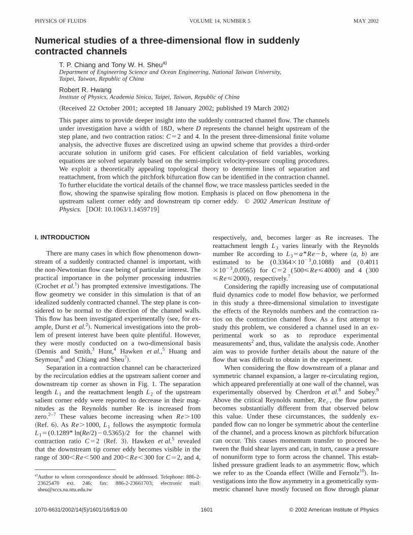
FIG. 2. Comparison of computed results under uniform and nonunifgrids in a two-dimensional channel withC52 andRe52000. ~a! Stream-wise velocity profiles;~b! pressure distribution along the downstream chanel roof–floor; ~c! vorticity distribution along the downstream channroof–floor.
rohes
ed
III. NUMERICAL MODEL
In solving the primitive-variable equations~1! and ~2!,together with the above-mentioned boundary conditions,employ a finite volume discretization method. A serioproblem worthy of consideration is that solutions to incopressible Navier–Stokes equations are prone to checkerbpressure oscillations. To circumvent this difficulty, field vaables are stored on staggered, interconnected grids. Foling the standard finite volume method, working equationsintegrated in their respective control volumes, each of whis associated with its representative primitive variable andplaced on the centroid of the control volume.
Numerical simulation of incompressible Navier–Stokequations leads to the convective instability problem. Phycally erroneous oscillatory velocities occur when dominatadvective terms are discretized using centered schemes.can result in numerical instability, which is particularly svere in multidimensional flow simulations. To fix this problem, we have modified the QUICK scheme~third-order ac-curacy! of Leonard20 and implemented it on nonuniformgrids. This modification not only resolves the convective
-
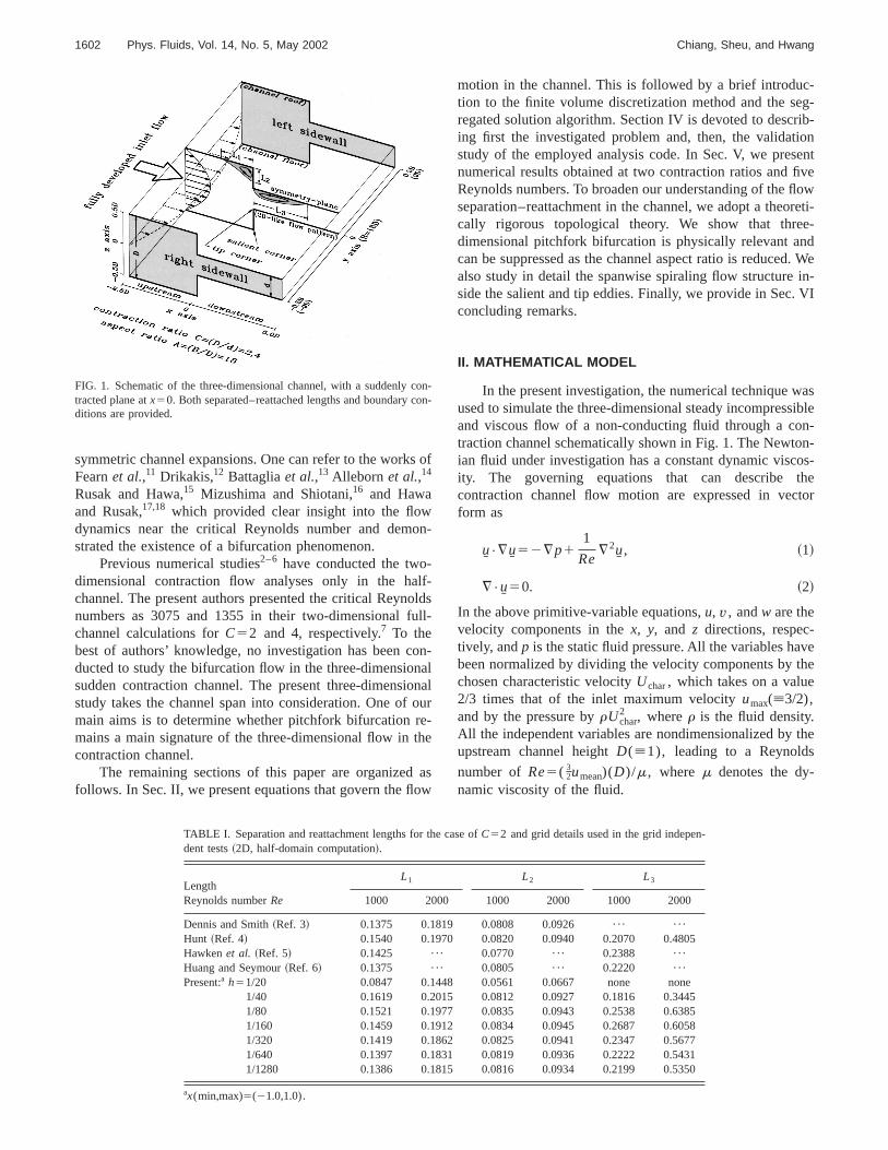
FIG. 3. ~a! Comparison of the computed two- and three-dimensional strewise velocity profiles at the plane of symmetry,y50, with the experimentaldata of Durstet al. ~Ref. 2! for the case withC54 and Re51150; ~b!comparison of the streamwise velocity profiles computed under the unifand nonuniform grids in a two-dimensional channel withC54 and Re51150.
ta
1604 Phys. Fluids, Vol. 14, No. 5, May 2002 Chiang, Sheu, and Hwang
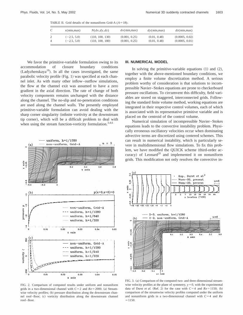
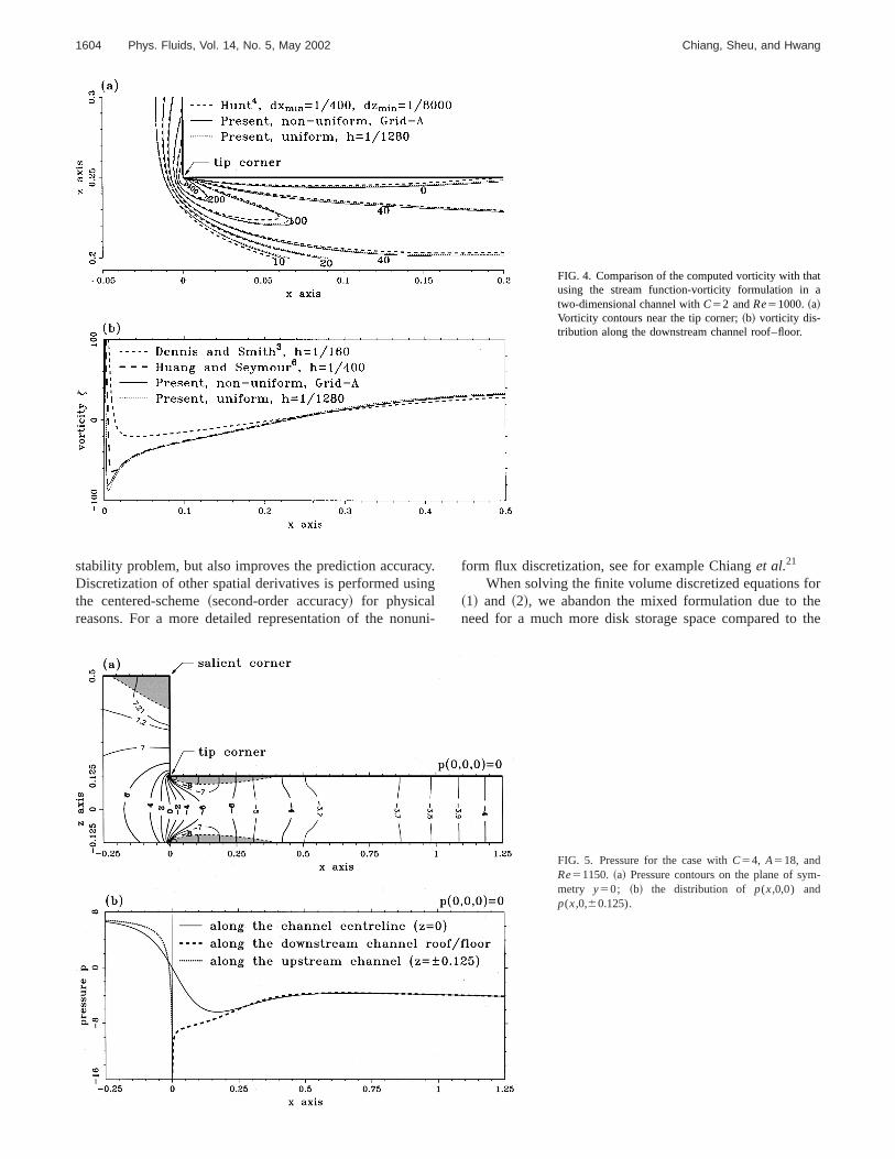
FIG. 4. Comparison of the computed vorticity with thausing the stream function-vorticity formulation intwo-dimensional channel withC52 andRe51000.~a!Vorticity contours near the tip corner;~b! vorticity dis-tribution along the downstream channel roof–floor.
cin
u
forethe
stability problem, but also improves the prediction accuraDiscretization of other spatial derivatives is performed usthe centered-scheme~second-order accuracy! for physicalreasons. For a more detailed representation of the non
y.g
ni-
form flux discretization, see for example Chianget al.21
When solving the finite volume discretized equations~1! and ~2!, we abandon the mixed formulation due to thneed for a much more disk storage space compared to
-
FIG. 5. Pressure for the case withC54, A518, andRe51150. ~a! Pressure contours on the plane of symmetry y50; ~b! the distribution of p(x,0,0) andp(x,0,60.125).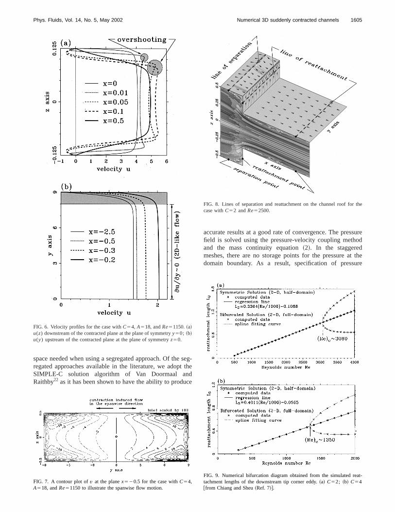
st tdc
sureod
t theure
the
at-
1605Phys. Fluids, Vol. 14, No. 5, May 2002 Numerical 3D suddenly contracted channels
space needed when using a segregated approach. Of theregated approaches available in the literature, we adopSIMPLE-C solution algorithm of Van Doormaal anRaithby22 as it has been shown to have the ability to produ
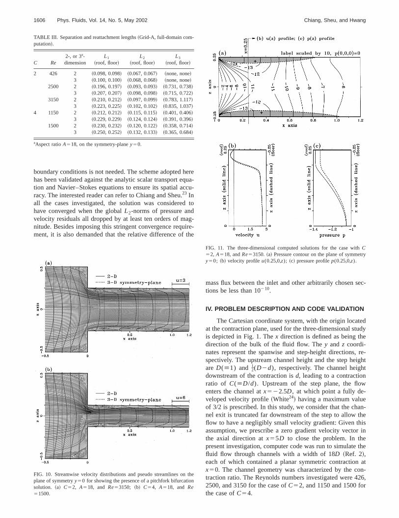
FIG. 6. Velocity profiles for the case withC54, A518, andRe51150.~a!u(z) downstream of the contracted plane at the plane of symmetryy50; ~b!u(y) upstream of the contracted plane at the plane of symmetryz50.
FIG. 7. A contour plot ofv at the planex520.5 for the case withC54,A518, andRe51150 to illustrate the spanwise flow motion.
eg-he
e
accurate results at a good rate of convergence. The presfield is solved using the pressure-velocity coupling methand the mass continuity equation~2!. In the staggeredmeshes, there are no storage points for the pressure adomain boundary. As a result, specification of press
FIG. 8. Lines of separation and reattachment on the channel roof forcase withC52 andRe52500.
FIG. 9. Numerical bifurcation diagram obtained from the simulated retachment lengths of the downstream tip corner eddy.~a! C52; ~b! C54@from Chiang and Sheu~Ref. 7!#.
hqcc.ddagirth
ec-
tedudye
, re-ightt
w
an-theisr in
the
aton-26,r
tn
hry
1606 Phys. Fluids, Vol. 14, No. 5, May 2002 Chiang, Sheu, and Hwang
boundary conditions is not needed. The scheme adoptedhas been validated against the analytic scalar transport etion and Navier–Stokes equations to ensure its spatial aracy. The interested reader can refer to Chiang and Sheu23 Inall the cases investigated, the solution was considerehave converged when the globalL2-norms of pressure anvelocity residuals all dropped by at least ten orders of mnitude. Besides imposing this stringent convergence requment, it is also demanded that the relative difference of
FIG. 10. Streamwise velocity distributions and pseudo streamlines onplane of symmetryy50 for showing the presence of a pitchfork bifurcatiosolution. ~a! C52, A518, and Re53150; ~b! C54, A518, and Re51500.
TABLE III. Separation and reattachment lengths~Grid-A, full-domain com-putation!.
C Re2-, or 3a-dimension
L1
~roof, floor!L2
~roof, floor!L3
~roof, floor!
2 426 2 ~0.098, 0.098! ~0.067, 0.067! ~none, none!3 ~0.100, 0.100! ~0.068, 0.068! ~none, none!
2500 2 ~0.196, 0.197! ~0.093, 0.093! ~0.731, 0.738!3 ~0.207, 0.207! ~0.098, 0.098! ~0.715, 0.722!
3150 2 ~0.210, 0.212! ~0.097, 0.099! ~0.783, 1.117!3 ~0.223, 0.225! ~0.102, 0.102! ~0.835, 1.037!
4 1150 2 ~0.212, 0.212! ~0.115, 0.115! ~0.401, 0.406!3 ~0.229, 0.229! ~0.124, 0.124! ~0.391, 0.396!
1500 2 ~0.230, 0.232! ~0.120, 0.122! ~0.358, 0.714!3 ~0.250, 0.252! ~0.132, 0.133! ~0.365, 0.684!
aAspect ratioA518, on the symmetry-planey50.
ereua-u-
to
-e-e
mass flux between the inlet and other arbitrarily chosen stions be less than 10210.
IV. PROBLEM DESCRIPTION AND CODE VALIDATION
The Cartesian coordinate system, with the origin locaat the contraction plane, used for the three-dimensional stis depicted in Fig. 1. Thex direction is defined as being thdirection of the bulk of the fluid flow. They and z coordi-nates represent the spanwise and step-height directionsspectively. The upstream channel height and the step heare D([1) and 1
2(D2d), respectively. The channel heighdownstream of the contraction isd, leading to a contractionratio of C([D/d). Upstream of the step plane, the floenters the channel atx522.5D, at which point a fully de-veloped velocity profile~White24! having a maximum valueof 3/2 is prescribed. In this study, we consider that the chnel exit is truncated far downstream of the step to allowflow to have a negligibly small velocity gradient: Given thassumption, we prescribe a zero gradient velocity vectothe axial direction atx55D to close the problem. In thepresent investigation, computer code was run to simulatefluid flow through channels with a width of 18D ~Ref. 2!,each of which contained a planar symmetric contractionx50. The channel geometry was characterized by the ctraction ratio. The Reynolds numbers investigated were 42500, and 3150 for the case ofC52, and 1150 and 1500 fothe case ofC54.
he
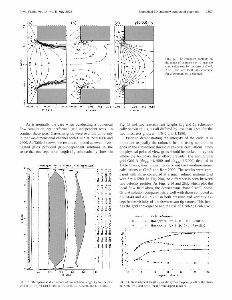
FIG. 11. The three-dimensional computed solutions for the case witC52, A518, andRe53150.~a! Pressure contour on the plane of symmety50; ~b! velocity profileu(0.25,0,z); ~c! pressure profilep(0.25,0,z).
n
1607Phys. Fluids, Vol. 14, No. 5, May 2002 Numerical 3D suddenly contracted channels
FIG. 12. The computed contours othe plane of symmetryy50 near thecontraction step for the case ofC54,A518, andRe51500.~a! u-contours;~b! w-contours;~c! p contours.
caTm
veth
ismromnsrm
nal-ridn
w,at-
ti-ill
As is normally the case when conducting a numeriflow simulation, we performed grid-independent tests.conduct these tests, Cartesian grids were overlaid uniforin the two-dimensional channel withC52 at Re51000 and2000. As Table I shows, the results computed at seven intigated grids provided grid-independent solutions insense that one separation length~L1 schematically shown in
FIG. 13. The spanwise distributions of reattachment lengthL3 for the casewith (C,A,Re)5(4,18,1150),~4,18,1500!, ~2,18,2500!, and~2,18,3150!.
loly
s-e
Fig. 1! and two reattachment lengths~L2 and L3 schemati-cally shown in Fig. 1! all differed by less than 1.5% for thetwo finest test grids,h51/640 and 1/1280.
Prior to demonstrating the integrity of the code, itimportant to justify the rationale behind using nonuniforgrids in the subsequent three-dimensional calculations. Fthe physical point of view, grids should be packed in regiowhere the boundary layer effect prevails. The nonunifogrid Grid-A ~dxmin51/1000 anddzmin51/2000! detailed inTable II was, thus, chosen to carry out the two-dimensiocalculations atC52 andRe52000. The results were compared with those computed at a much refined uniform gwith h51/1280. In Fig. 2~a!, no difference is seen betweetwo velocity profiles. As Figs. 2~b! and 2~c!, which plot thelocal flow field along the downstream channel wall, shoGrid-A solution compares fairly well with those computedh51/640 andh51/1280 in both pressure and vorticity except in the vicinity of the downstream tip corner. This jusfies the grid convergence and the use of Grid-A; Grid-A w
FIG. 14. Reattachment lengthL3 on the symmetry-planey50 of the chan-nel with C52 andC54 for different aspect ratiosA.
sym
1608 Phys. Fluids, Vol. 14, No. 5, May 2002 Chiang, Sheu, and Hwang
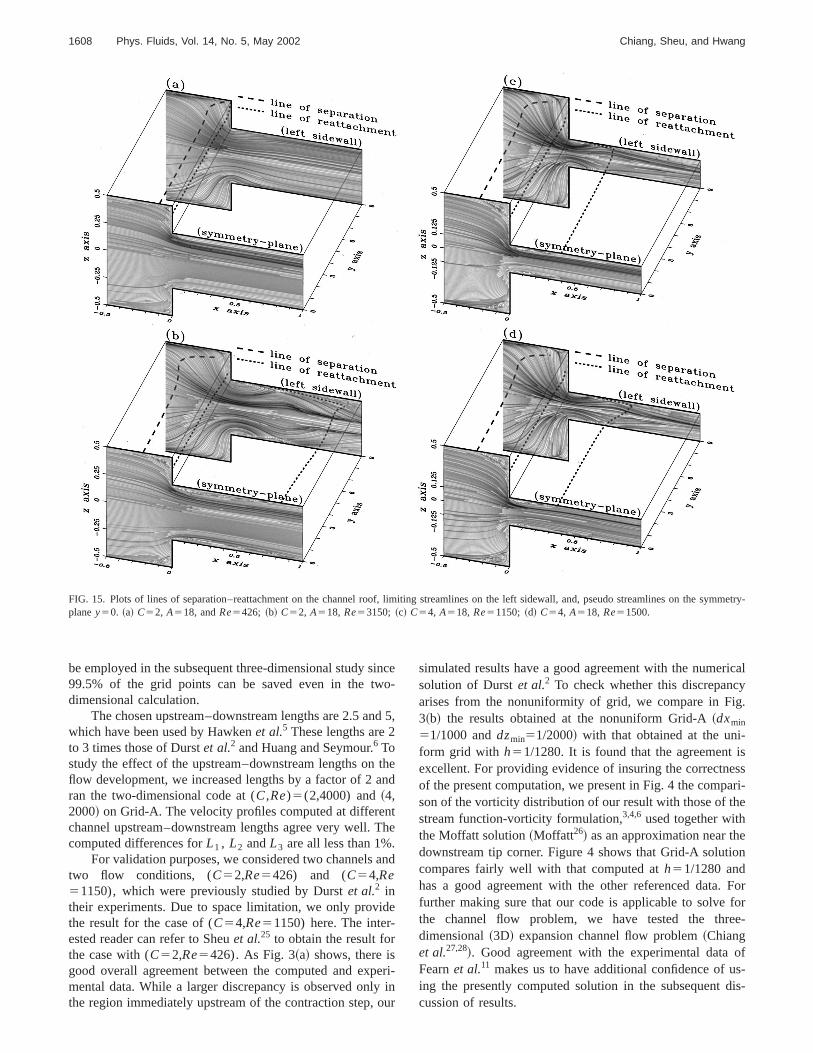
FIG. 15. Plots of lines of separation–reattachment on the channel roof, limiting streamlines on the left sidewall, and, pseudo streamlines on themetry-planey50. ~a! C52, A518, andRe5426; ~b! C52, A518, Re53150; ~c! C54, A518, Re51150; ~d! C54, A518, Re51500.
ino
nd
tan
ntT.an
ide
peyo
ricalyg.
-isessari-e
eon
Forforee-
ofs-
dis-
be employed in the subsequent three-dimensional study s99.5% of the grid points can be saved even in the twdimensional calculation.
The chosen upstream–downstream lengths are 2.5 awhich have been used by Hawkenet al.5 These lengths are 2to 3 times those of Durstet al.2 and Huang and Seymour.6 Tostudy the effect of the upstream–downstream lengths onflow development, we increased lengths by a factor of 2ran the two-dimensional code at (C,Re)5(2,4000) and~4,2000! on Grid-A. The velocity profiles computed at differechannel upstream–downstream lengths agree very well.computed differences forL1 , L2 andL3 are all less than 1%
For validation purposes, we considered two channelstwo flow conditions, (C52,Re5426) and (C54,Re51150), which were previously studied by Durstet al.2 intheir experiments. Due to space limitation, we only provthe result for the case of (C54,Re51150) here. The inter-ested reader can refer to Sheuet al.25 to obtain the result forthe case with (C52,Re5426). As Fig. 3~a! shows, there isgood overall agreement between the computed and exmental data. While a larger discrepancy is observed onlthe region immediately upstream of the contraction step,
ce-
5,
hed
he
d
ri-inur
simulated results have a good agreement with the numesolution of Durstet al.2 To check whether this discrepancarises from the nonuniformity of grid, we compare in Fi3~b! the results obtained at the nonuniform Grid-A~dxmin
51/1000 anddzmin51/2000! with that obtained at the uniform grid with h51/1280. It is found that the agreementexcellent. For providing evidence of insuring the correctnof the present computation, we present in Fig. 4 the compson of the vorticity distribution of our result with those of thstream function-vorticity formulation,3,4,6 used together withthe Moffatt solution~Moffatt26! as an approximation near thdownstream tip corner. Figure 4 shows that Grid-A soluticompares fairly well with that computed ath51/1280 andhas a good agreement with the other referenced data.further making sure that our code is applicable to solvethe channel flow problem, we have tested the thrdimensional~3D! expansion channel flow problem~Chianget al.27,28!. Good agreement with the experimental dataFearnet al.11 makes us to have additional confidence of uing the presently computed solution in the subsequentcussion of results.
t-r
1609Phys. Fluids, Vol. 14, No. 5, May 2002 Numerical 3D suddenly contracted channels
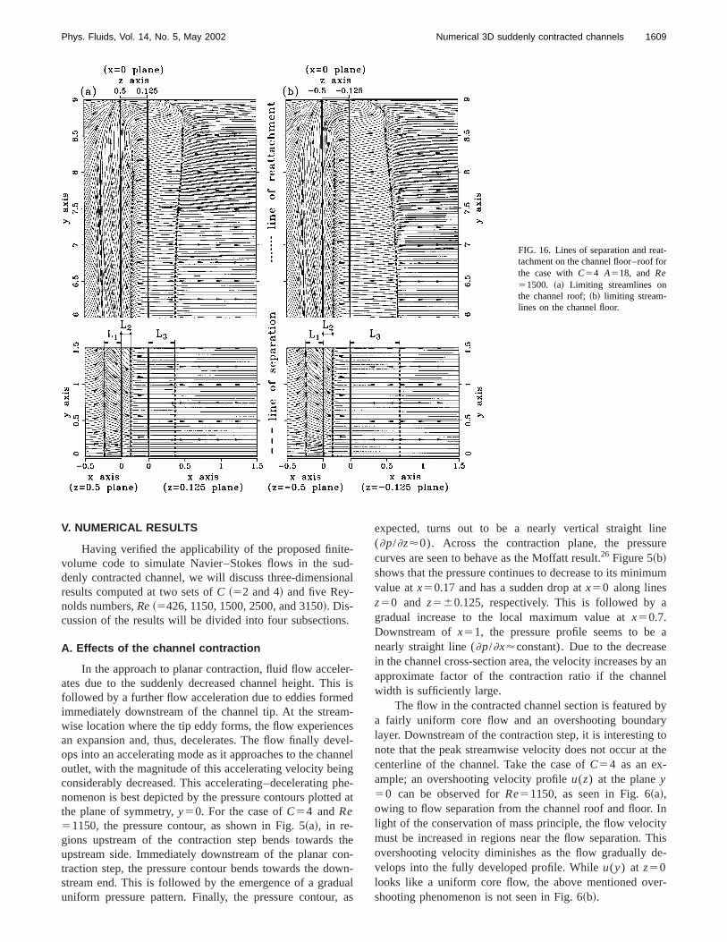
FIG. 16. Lines of separation and reatachment on the channel floor–roof fothe case withC54 A518, and Re51500. ~a! Limiting streamlines onthe channel roof;~b! limiting stream-lines on the channel floor.
e-udn
s.
erisemcevenngpd
towu
,
inere
um
a
aey anel
byrytothe
Inity
hise-
er-
V. NUMERICAL RESULTS
Having verified the applicability of the proposed finitvolume code to simulate Navier–Stokes flows in the sdenly contracted channel, we will discuss three-dimensioresults computed at two sets ofC ~52 and 4! and five Rey-nolds numbers,Re~5426, 1150, 1500, 2500, and 3150!. Dis-cussion of the results will be divided into four subsection
A. Effects of the channel contraction
In the approach to planar contraction, fluid flow accelates due to the suddenly decreased channel height. Thfollowed by a further flow acceleration due to eddies formimmediately downstream of the channel tip. At the streawise location where the tip eddy forms, the flow experienan expansion and, thus, decelerates. The flow finally deops into an accelerating mode as it approaches to the chaoutlet, with the magnitude of this accelerating velocity beiconsiderably decreased. This accelerating–deceleratingnomenon is best depicted by the pressure contours plottethe plane of symmetry,y50. For the case ofC54 andRe51150, the pressure contour, as shown in Fig. 5~a!, in re-gions upstream of the contraction step bends towardsupstream side. Immediately downstream of the planar ctraction step, the pressure contour bends towards the dostream end. This is followed by the emergence of a graduniform pressure pattern. Finally, the pressure contour
-al
-is
d-sl-
nel
he-at
hen-n-alas
expected, turns out to be a nearly vertical straight l(]p/]z'0). Across the contraction plane, the pressucurves are seen to behave as the Moffatt result.26 Figure 5~b!shows that the pressure continues to decrease to its minimvalue atx50.17 and has a sudden drop atx50 along linesz50 and z560.125, respectively. This is followed bygradual increase to the local maximum value atx50.7.Downstream ofx51, the pressure profile seems to benearly straight line (]p/]x'constant). Due to the decreasin the channel cross-section area, the velocity increases bapproximate factor of the contraction ratio if the channwidth is sufficiently large.
The flow in the contracted channel section is featureda fairly uniform core flow and an overshooting boundalayer. Downstream of the contraction step, it is interestingnote that the peak streamwise velocity does not occur atcenterline of the channel. Take the case ofC54 as an ex-ample; an overshooting velocity profileu(z) at the planey50 can be observed forRe51150, as seen in Fig. 6~a!,owing to flow separation from the channel roof and floor.light of the conservation of mass principle, the flow velocmust be increased in regions near the flow separation. Tovershooting velocity diminishes as the flow gradually dvelops into the fully developed profile. Whileu(y) at z50looks like a uniform core flow, the above mentioned ovshooting phenomenon is not seen in Fig. 6~b!.
sera
esarrs
uid
bsth
-ice
ennin
eso
son
onthiob
10
d
etrntr
n
nbf
.llyths
nlue-
s-
-
1et-
y
rtery.the
theare
s
hea
on-tricectnorsgo-
1610 Phys. Fluids, Vol. 14, No. 5, May 2002 Chiang, Sheu, and Hwang
We will next consider the end-wall induced spanwiflow motion in channels having a planar contraction. Figu6~b! shows that]u/]x near the sidewall boundary layer hasvalue larger than that in the core region. This accompaninegative pressure gradient and, thus, the flow moves towthe two vertical sidewalls. To confirm this, we plot contouof v at a streamwise planex520.5. As Fig. 7 shows, thespanwise flow motion is revealed by the movement of flparticles to the vertical sidewall.
B. Eddy size and pitchfork bifurcation
The suddenly contracted channel flow manifests itselfthe presence of re-circulating eddies. An effective meandetermining these eddy sizes is, therefore, needed. Instudy, we adopted the topological theory~Legendre29 andLighthill !.30 Among the available vector fields, we chose limiting streamlines in the present three-dimensional topologstudy. Limiting streamlines are, by definition, streamlinimmediately above the solid wall.29 Take the case with(C,Re)5(2,2500) as an example; we can theoretically dtermine lines of separation and reattachment on the charoof from the limiting streamlines plotted in Fig. 8. This,turn, enables us to determine three typical lengthsL1 , L2 ,andL3 , schematically shown in Fig. 1.
Whether or not flow bifurcation of the pitchfork typoccurs depends on the channel contraction ratio as well athe Reynolds number. Based on our previous twdimensional results7 shown in Fig. 9, the critical Reynoldnumbers beyond which flow started to exhibit bifurcatisolutions were determined as 3080 and 1350 forC52 and 4,respectively. With reference to these critical values, we csidered Reynolds numbers, tabulated in Table III, inpresent three-dimensional studies. It was found that solutreveal unequal roof–floor eddy sizes as the Reynolds numexceeded its critical value. The evidence is given in Fig.which plotsu-w pseudo streamlines and theu-velocity pro-file at the plane of symmetry,y50, for cases characterizeby (C,Re)5(2,3150) and~4,1500!. Figure 10 also showsthat the reattachment lengthsL3uroof andL3ufloor are substan-tially different. It is the symmetric flow state in the channthat may lose its stability and transit to a stable asymmestate. The circulating eddies formed immediately dowstream of the contraction plane no longer can be symmewith respect to the symmetry planez50. Unlike the down-stream reattachment length, the upstream separation leL1 and reattachment lengthL2 on the channel roof remainthe same as those at the channel floor. This observatiotrue over all the investigated test conditions detailed in TaIII, which tabulatesL1 , L2 , andL3 obtained at the plane osymmetry, y50. The maximum differences forL1uroof
2L1ufloor and L2uroof2L2ufloor are found to be less than 1%To show that such a pitchfork bifurcating flow is physicarelevant and is not numerically produced, we perturbedsolutions by an amount of 10 to 20 percentage for the castudied at (C,Re)5(2,3150) and~4,1500!. Both solutionsobtained under the stringent convergence criteria mentioearlier are seen to produce their original bifurcation sotions, implying that it is possible to have the thre
e
ads
yofis
als
-el
on-
-enser,
lic-ic
gth
isle
ees
ed-
dimensional pitchfork bifurcation flow in the presently invetigated planar symmetric sudden-contracted channel.
The flow atRe53150 can no longer be configured symmetrically with respect toz50 in the channel withC52.Under these circumstances, the pressure plotted in Fig. 1~a!exhibits noz-symmetry contours in response to the asymmric velocity profile shown in Fig. 10~a!. To gain deeper in-sight into the pitchfork bifurcation flow, we plot the velocitand pressure profiles atx50.25 in Figs. 11~b! and 11~c!. Ofthe two downstream tip eddies, the roof eddy has a sholengthL3 and a larger velocity than those of the floor eddOn the other hand, a larger pressure value is observed infloor eddy. Also, a larger pressure gradient is found inroof eddy. The differences in pressure and velocitygradually reduced in the approach toz50.
Table III indicates an indication of which flow exhibitpitchfork bifurcation for two channels with (A,C)5(18,2)and ~18,4!. It has been known for quite some time that texperimentally observed bifurcation is triggered by evensmall asymmetry in the channel geometry and inlet flow cditions. In contrast, we attribute the predicted asymmesolutions in a geometrically symmetric channel flow, subjto a perfect symmetric inlet flow condition, to bifurcatiotriggered, possibly, by the asymmetric discretization errand/or asymmetry in the direction-biased numerical al
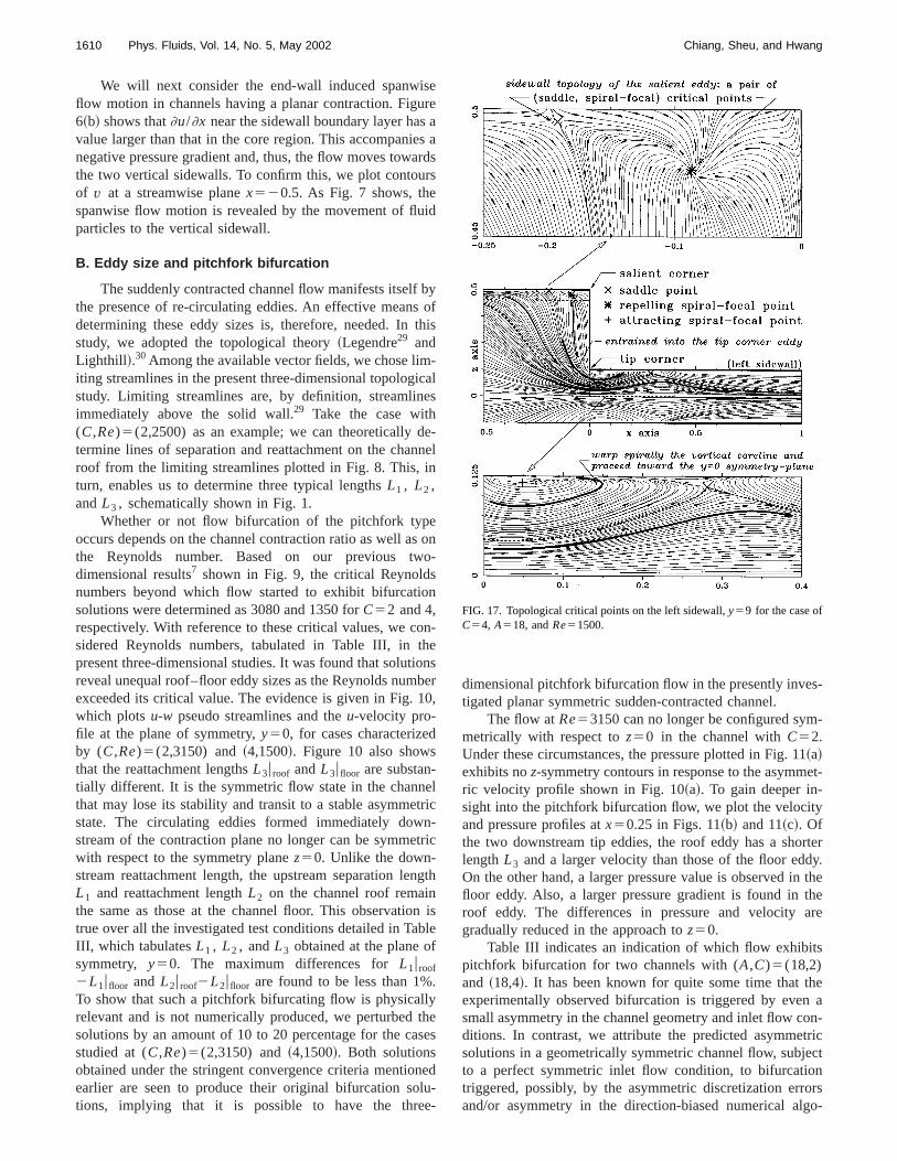
FIG. 17. Topological critical points on the left sidewall,y59 for the case ofC54, A518, andRe51500.
th
1611Phys. Fluids, Vol. 14, No. 5, May 2002 Numerical 3D suddenly contracted channels
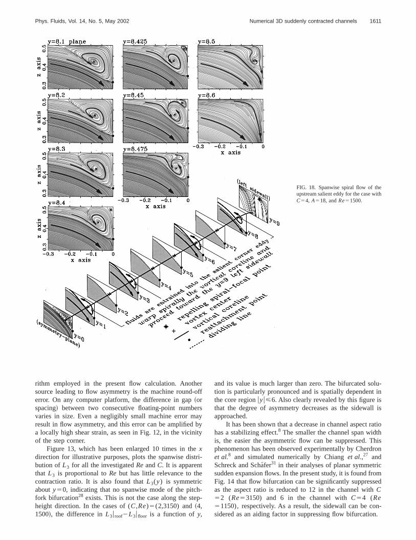
FIG. 18. Spanwise spiral flow of theupstream salient eddy for the case wiC54, A518, andRe51500.
e-o
rsabit
etr
e
hp
lu-t insll is
ratiothThisdron
icomed
on-n.
rithm employed in the present flow calculation. Anothsource leading to flow asymmetry is the machine rounderror. On any computer platform, the difference in gap~orspacing! between two consecutive floating-point numbevaries in size. Even a negligibly small machine error mresult in flow asymmetry, and this error can be amplifieda locally high shear strain, as seen in Fig. 12, in the vicinof the step corner.
Figure 13, which has been enlarged 10 times in thxdirection for illustrative purposes, plots the spanwise disbution of L3 for all the investigatedReandC. It is apparentthat L3 is proportional toRe but has little relevance to thcontraction ratio. It is also found thatL3(y) is symmetricabouty50, indicating that no spanwise mode of the pitcfork bifurcation28 exists. This is not the case along the steheight direction. In the cases of (C,Re)5(2,3150) and~4,1500!, the difference inL3uroof2L3ufloor is a function ofy,
rff
yyy
i-
--
and its value is much larger than zero. The bifurcated sotion is particularly pronounced and is spatially dependenthe core regionuyu<6. Also clearly revealed by this figure ithat the degree of asymmetry decreases as the sidewaapproached.
It has been shown that a decrease in channel aspecthas a stabilizing effect.8 The smaller the channel span widis, the easier the asymmetric flow can be suppressed.phenomenon has been observed experimentally by Cheret al.8 and simulated numerically by Chianget al.,27 andSchreck and Scha¨fer31 in their analyses of planar symmetrsudden expansion flows. In the present study, it is found frFig. 14 that flow bifurcation can be significantly suppressas the aspect ratio is reduced to 12 in the channel withC52 (Re53150) and 6 in the channel withC54 (Re51150), respectively. As a result, the sidewall can be csidered as an aiding factor in suppressing flow bifurcatio
nrgrnisg
imthn,thi
siton
ngotu
anofermslysseine
irao-irall
anfe
enng
it-a
ofer
thet
fdear-thistho
io
anwn-bits
byeft
-ne
onlarddleentintthe
ameat-tedthe
sand,t ofr in
isdleisrvedan-
e
e co-
1612 Phys. Fluids, Vol. 14, No. 5, May 2002 Chiang, Sheu, and Hwang
C. Flow topology
When performing a three-dimensional flow simulatiowe are often faced with the tedious task of managing a laamount of data. Care must be appropriately taken in ordeextract meaningful flow physics and then obtain a profouunderstanding of the flow structure. In the literature, itfound that we can conduct a theoretically rigorous topolocal study on limiting streamlines29 or skin-friction lines30 toachieve this goal. In this study, the method that exploits liting streamlines was chosen to gain physical insight intopertinent fluid flow. Limiting streamlines are, by definitiostreamlines passing very close to the wall surface. Astopological theory states, limiting streamlines, as shownFig. 8, tend to diverge from lines of attachment. The oppoof lines of attachment are lines of separation. To linesseparation, neighboring limiting streamlines tend to coverge. We make use of the kinematic nature of limitistreamlines to classify singular points, such as nodes, fand saddles, which enable us to depict the flow strucinferred from the three-dimensional data.
The first step in presenting a global picture of the chnel flow was to plot limiting streamlines and linesseparation/reattachment at the channel roof, floor and vcal sidewalls and pseudo streamlines at the plane of symtry y50 for the investigated flow conditions. Except the cawith Re5426 andC52, salient and tip eddies can be clearseen in the region ofuyu<8. These eddies became increaingly less apparent in the rest of the spanwise range, asin Fig. 15. The flow near the sidewall is featured by a dimishing spiral flow motion. The spiraling salient eddy passover the contraction step and, finally, terminates at the spfocal point. As for the downstream tip eddy, its motion twards the sidewall is still featured by a less apparent sping motion. It is also worth noting that the sidewastreamlines differ considerably from streamlines at the plof symmetryy50. Figure 15 reveals limiting streamlines othe convergence–divergence–convergence type at the vcal sidewall. This flow complexity is the result of a suddchange in the channel cross section and the increasidominant viscous effect near the no-slip sidewall.
Having depicted the flow topology, we plotted the liming streamlines on the channel roof and floor. Take the cwith C54 andRe51500 as an illustrative example. Linesreattachment and separation, which are used to charactthe spanwise sizesL1(y), L2(y) andL3(y) of the salient aswell as the tip eddies, are plotted in Fig. 16. Upstream ofplanar step atx50, limiting streamlines bend towards thvertical sidewall such that lines of separation are seen atchannel floor and roof. It is apparent that the spanwise mtion prevails inside the upstream salient eddy. The reasonthe movement of the fluid particles towards the vertical siwall is a sudden decrease in the channel cross-sectionNear the sidewall, sayuyu>8, particles inside the downstream tip eddy are seen to repel from the sidewall. Inspanwise range ofuyu<8, clearly seen is a tip eddy, whichreattached to the channel floor or roof. In the core region,spanwise velocity is so small that the flow is essentially twdimensional. Of two eddies which form near the contract
,etod
i-
-e
enef-
ci,re
-
ti-e-
e
-en
-sl-
l-
e
rti-
ly
se
ize
e
heo-or-ea.
e
e-n
step, the flow inside the upstream salient eddy showsapparent spanwise motion, as compared to that in the dostream tip eddy. This implies that the upstream eddy exhia three-dimensional spiraling flow feature.
We then explored the contraction channel flowsketching the sidewall limiting streamlines. Take the lsidewall as an example; we plot in Fig. 17 limiting streamlines on the plane which is immediately adjacent to the play59 for the case withC54 andRe51500. One noteworthyfeature of the sidewall limiting streamlines is the formatiof two pairs of singular points. These topologically singupoints can be classified as saddles and nodal points. Sapoints are defined as having two real eigenvalues of differsigns. The limiting streamlines approach the saddle poalong the negative eigendirection while they recede alongpositive eigendirection. Nodal points~or regular nodalpoints! are defined as having the real eigenvalues of the ssign. These singular points can be further divided intotracting and repelling types. Attracting nodes are associawith the negative real eigenvalue, and repelling nodes doreverse. Foci~or spiral-focal points! are also referred to asingular points, whose eigenvalues are, on the other hconjugate complex. Depending on the sign of the real parthe eigenvalue, adjacent limiting streamlines spiral eitheor out of the singular point.
Following the above topological classification, itfound that each pair of singular points contains a sadpoint and a spiral-focal point. One pair of critical pointsseen in the upstream salient eddy, and the other is obseat the downstream tip eddy. Owing to the sign of the sp
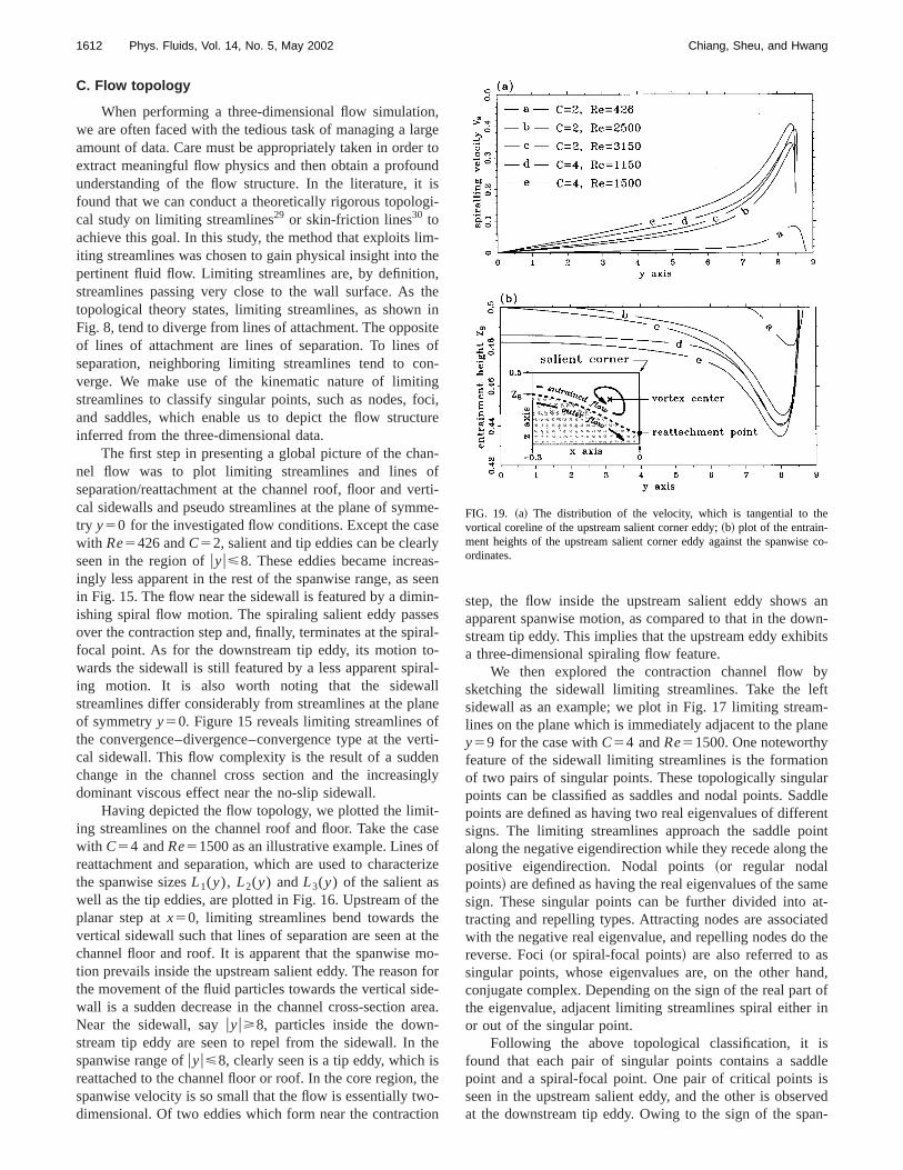
FIG. 19. ~a! The distribution of the velocity, which is tangential to thvortical coreline of the upstream salient corner eddy;~b! plot of the entrain-ment heights of the upstream salient corner eddy against the spanwisordinates.
1613Phys. Fluids, Vol. 14, No. 5, May 2002 Numerical 3D suddenly contracted channels
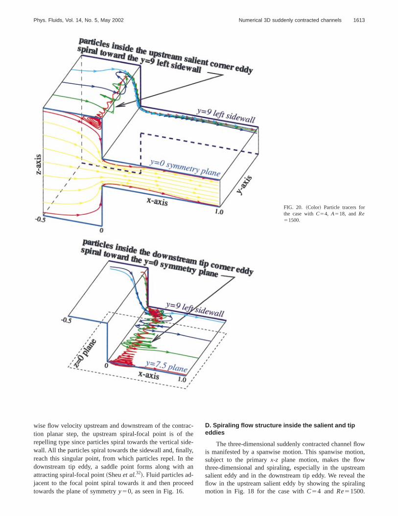
FIG. 20. ~Color! Particle tracers forthe case withC54, A518, andRe51500.
acthdely,hea
e
owion,
amthe
ing
wise flow velocity upstream and downstream of the contrtion planar step, the upstream spiral-focal point is ofrepelling type since particles spiral towards the vertical siwall. All the particles spiral towards the sidewall and, finalreach this singular point, from which particles repel. In tdownstream tip eddy, a saddle point forms along withattracting spiral-focal point~Sheuet al.32!. Fluid particles ad-jacent to the focal point spiral towards it and then procetowards the plane of symmetryy50, as seen in Fig. 16.
-e-
n
d
D. Spiraling flow structure inside the salient and tipeddies
The three-dimensional suddenly contracted channel flis manifested by a spanwise motion. This spanwise motsubject to the primaryx-z plane motion, makes the flowthree-dimensional and spiraling, especially in the upstresalient eddy and in the downstream tip eddy. We revealflow in the upstream salient eddy by showing the spiralmotion in Fig. 18 for the case withC54 and Re51500.
1614 Phys. Fluids, Vol. 14, No. 5, May 2002 Chiang, Sheu, and Hwang
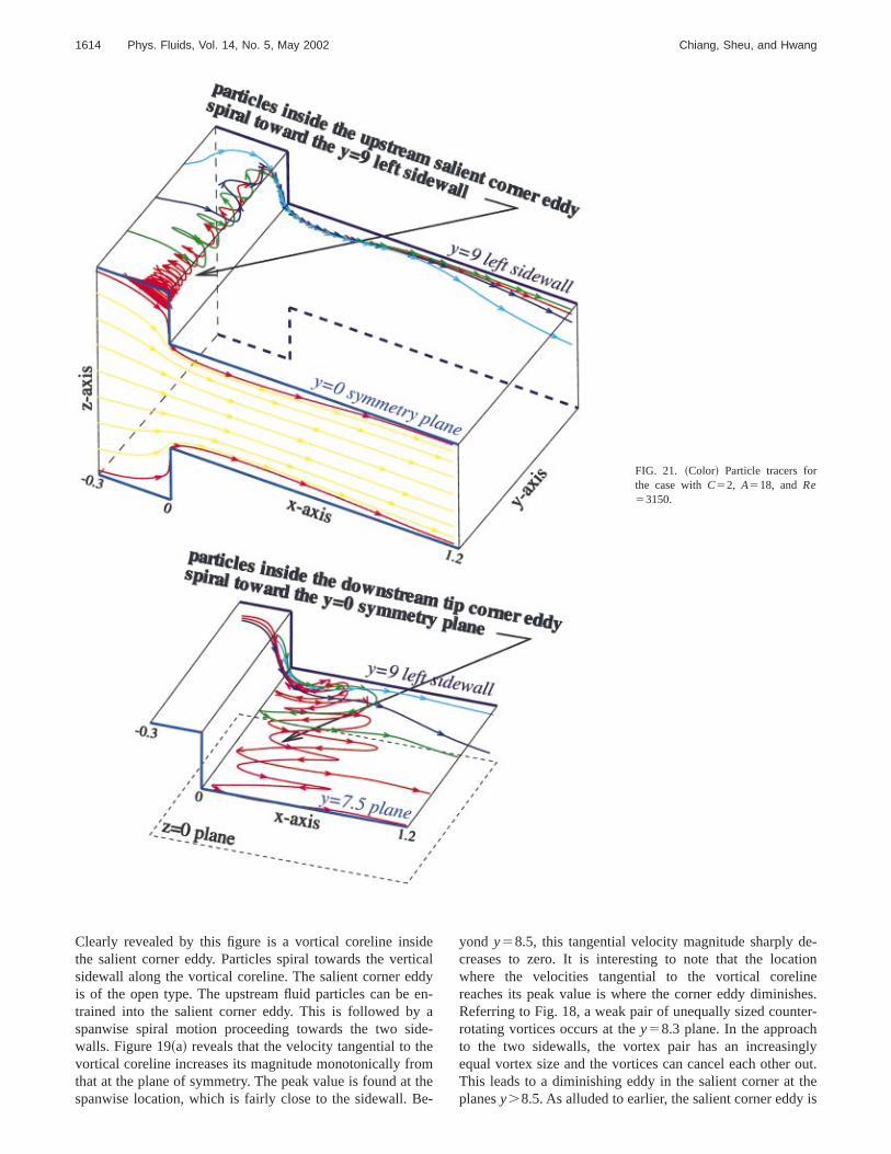
FIG. 21. ~Color! Particle tracers forthe case withC52, A518, andRe53150.
deicdea
dee
omthe
e-ionnehes.er-hglyout.theis
Clearly revealed by this figure is a vortical coreline insithe salient corner eddy. Particles spiral towards the vertsidewall along the vortical coreline. The salient corner edis of the open type. The upstream fluid particles can betrained into the salient corner eddy. This is followed byspanwise spiral motion proceeding towards the two siwalls. Figure 19~a! reveals that the velocity tangential to thvortical coreline increases its magnitude monotonically frthat at the plane of symmetry. The peak value is found atspanwise location, which is fairly close to the sidewall. B
alyn-
-
e-
yond y58.5, this tangential velocity magnitude sharply dcreases to zero. It is interesting to note that the locatwhere the velocities tangential to the vortical corelireaches its peak value is where the corner eddy diminisReferring to Fig. 18, a weak pair of unequally sized countrotating vortices occurs at they58.3 plane. In the approacto the two sidewalls, the vortex pair has an increasinequal vortex size and the vortices can cancel each otherThis leads to a diminishing eddy in the salient corner atplanesy.8.5. As alluded to earlier, the salient corner eddy
ind
t
heononum
esith-.ddtic
b-fa
nethnpidwtr
rtle
intheage
nten
ons00,ri-
forkthetheaveuidten-amheint.
ofn-lesof
alre-
umtexup-ach
intof
alC
dn,’’
h aer.
dInt.
on
a
e
ta-
J.
ol-
a
ion
al
1615Phys. Fluids, Vol. 14, No. 5, May 2002 Numerical 3D suddenly contracted channels
not of the close type, so the upstream flow can be entrainto the corner eddy. The height of such an open-type edzs, schematically shown in Fig. 19~b!, was plotted againsthe spanwise coordinatey. Surprisingly, Fig. 19~b! showsthat zs increases monotonically in the direction towards tvertical sidewall. It is found that at the spanwise locatiwherezs reaches its peak value, the velocity in the directitangential to the vortical coreline also reaches its maximvalue.
We then discussed spiraling flow motion in the corneddy by varyingC and Re. For all the investigated casethey vary in a manner similar to that found in the case wRe51500 andC54. The effects ofC and Re are best revealed by Figs. 19~a! and 19~b! for the readers’ referenceThe spanwise spiraling motions in the upstream salient eand the downstream tip eddy are best shown by the parmotions in Figs. 20 and 21 for the cases with (C,Re)5(4,1500) and~2,3150!, respectively. These plots were otained by tracing massless particles seeded upstream oplanar step. Particles that are fairly close to the sidew(uyu.8.9) in the upstream salient corner tend to be entraiinto the downstream tip eddy and to proceed towardsattracting spiral-focal point shown in Fig. 17. These etrained particles show a spiraling-type motion in their aproach to the plane of symmetry. Unlike the particles insthe upstream salient corner eddy, the particles in the dostream tip eddy partly spiral towards the plane of symmey50 due to the local sidewall entrainment effect and pamove towards the sidewall due to the global contractionfect.
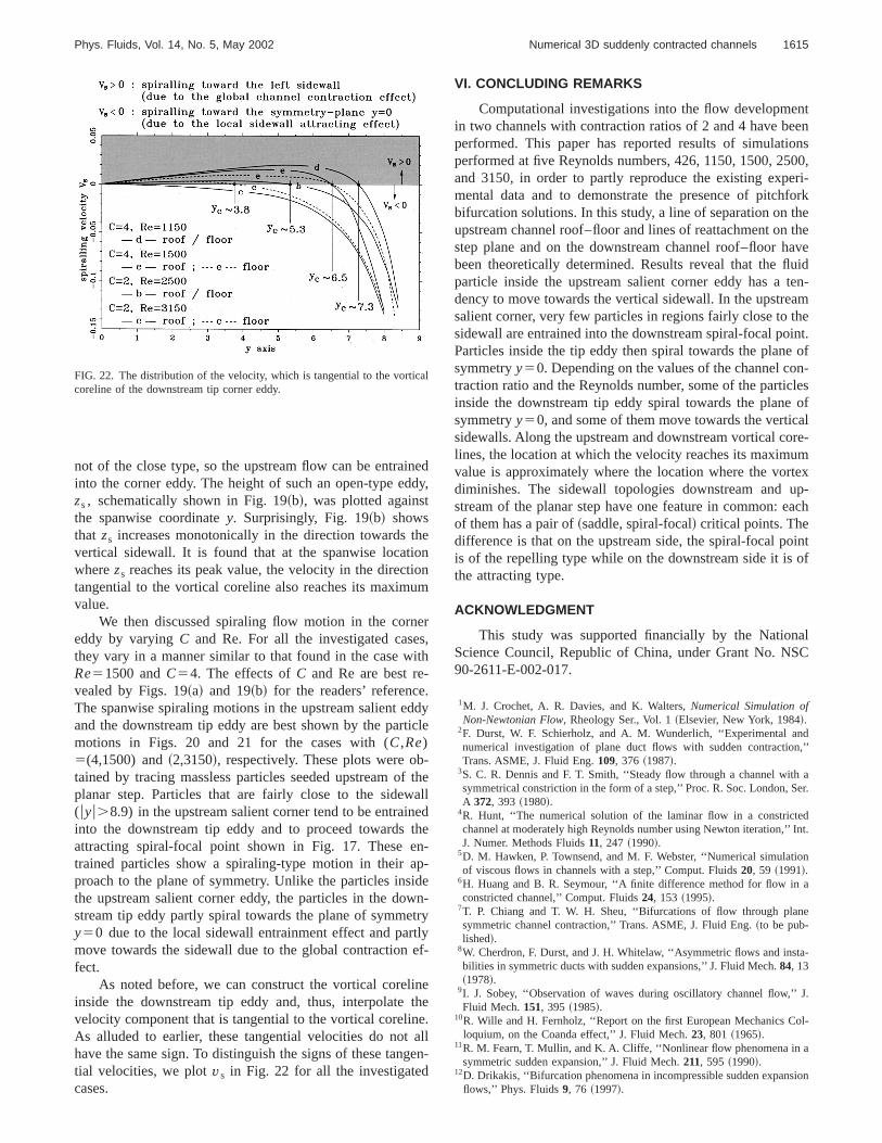
As noted before, we can construct the vortical corelinside the downstream tip eddy and, thus, interpolatevelocity component that is tangential to the vortical corelinAs alluded to earlier, these tangential velocities do nothave the same sign. To distinguish the signs of these tantial velocities, we plotvs in Fig. 22 for all the investigatedcases.
FIG. 22. The distribution of the velocity, which is tangential to the vorticcoreline of the downstream tip corner eddy.
edy,
r,
yle
thellde--en-yyf-
ee.lln-
VI. CONCLUDING REMARKS
Computational investigations into the flow developmein two channels with contraction ratios of 2 and 4 have beperformed. This paper has reported results of simulatiperformed at five Reynolds numbers, 426, 1150, 1500, 25and 3150, in order to partly reproduce the existing expemental data and to demonstrate the presence of pitchbifurcation solutions. In this study, a line of separation onupstream channel roof–floor and lines of reattachment onstep plane and on the downstream channel roof–floor hbeen theoretically determined. Results reveal that the flparticle inside the upstream salient corner eddy has adency to move towards the vertical sidewall. In the upstresalient corner, very few particles in regions fairly close to tsidewall are entrained into the downstream spiral-focal poParticles inside the tip eddy then spiral towards the planesymmetryy50. Depending on the values of the channel cotraction ratio and the Reynolds number, some of the particinside the downstream tip eddy spiral towards the planesymmetryy50, and some of them move towards the verticsidewalls. Along the upstream and downstream vortical colines, the location at which the velocity reaches its maximvalue is approximately where the location where the vordiminishes. The sidewall topologies downstream andstream of the planar step have one feature in common: eof them has a pair of~saddle, spiral-focal! critical points. Thedifference is that on the upstream side, the spiral-focal pois of the repelling type while on the downstream side it isthe attracting type.
ACKNOWLEDGMENT
This study was supported financially by the NationScience Council, Republic of China, under Grant No. NS90-2611-E-002-017.
1M. J. Crochet, A. R. Davies, and K. Walters,Numerical Simulation ofNon-Newtonian Flow, Rheology Ser., Vol. 1~Elsevier, New York, 1984!.
2F. Durst, W. F. Schierholz, and A. M. Wunderlich, ‘‘Experimental annumerical investigation of plane duct flows with sudden contractioTrans. ASME, J. Fluid Eng.109, 376 ~1987!.
3S. C. R. Dennis and F. T. Smith, ‘‘Steady flow through a channel witsymmetrical constriction in the form of a step,’’ Proc. R. Soc. London, SA 372, 393 ~1980!.
4R. Hunt, ‘‘The numerical solution of the laminar flow in a constrictechannel at moderately high Reynolds number using Newton iteration,’’J. Numer. Methods Fluids11, 247 ~1990!.
5D. M. Hawken, P. Townsend, and M. F. Webster, ‘‘Numerical simulatiof viscous flows in channels with a step,’’ Comput. Fluids20, 59 ~1991!.
6H. Huang and B. R. Seymour, ‘‘A finite difference method for flow inconstricted channel,’’ Comput. Fluids24, 153 ~1995!.
7T. P. Chiang and T. W. H. Sheu, ‘‘Bifurcations of flow through plansymmetric channel contraction,’’ Trans. ASME, J. Fluid Eng.~to be pub-lished!.
8W. Cherdron, F. Durst, and J. H. Whitelaw, ‘‘Asymmetric flows and insbilities in symmetric ducts with sudden expansions,’’ J. Fluid Mech.84, 13~1978!.
9I. J. Sobey, ‘‘Observation of waves during oscillatory channel flow,’’Fluid Mech.151, 395 ~1985!.
10R. Wille and H. Fernholz, ‘‘Report on the first European Mechanics Cloquium, on the Coanda effect,’’ J. Fluid Mech.23, 801 ~1965!.
11R. M. Fearn, T. Mullin, and K. A. Cliffe, ‘‘Nonlinear flow phenomena insymmetric sudden expansion,’’ J. Fluid Mech.211, 595 ~1990!.
12D. Drikakis, ‘‘Bifurcation phenomena in incompressible sudden expansflows,’’ Phys. Fluids9, 76 ~1997!.
n
ri-uid
ohy
nn
e
tric
s-
urpp
ods
LEfe
in
onnals of
uid
hen,’’
ur-
-
in
nel
1616 Phys. Fluids, Vol. 14, No. 5, May 2002 Chiang, Sheu, and Hwang
13F. Battaglia, S. J. Tavener, A. K. Kulkarni, and C. L. Merkle, ‘‘Bifurcatioof low Reynolds number flows in symmetric channels,’’ AIAA J.35, 99~1997!.
14N. Alleborn, K. Nandakumar, H. Raszillier, and F. Durst, ‘‘Further contbutions on the two-dimensional flow in a sudden expansion,’’ J. FlMech.330, 169 ~1997!.
15Z. Rusak and T. Hawa, ‘‘A weakly nonlinear analysis of the dynamicsa viscous flow in a symmetric channel with a sudden expansion,’’ PFluids 11, 3629~1999!.
16J. Mizushima and Y. Shiotani, ‘‘Structural instability of the bifurcatiodiagram for two-dimensional flow in a channel with a sudden expansioJ. Fluid Mech.420, 131 ~2000!.
17T. Hawa and Z. Rusak, ‘‘Viscous flow in a slightly asymmetric channwith a sudden expansion,’’ Phys. Fluids12, 2257~2000!.
18T. Hawa and Z. Rusak, ‘‘The dynamics of a laminar flow in a symmechannel with a sudden expansion,’’ J. Fluid Mech.436, 283 ~2001!.
19O. A. Ladyzhenskaya,Mathematical Problems in the Dynamics of a Vicous Incompressible Flow~Gordon & Breach, New York, 1963!.
20B. P. Leonard, ‘‘A stable and accurate convective modeling procedbased on quadratic upstream interpolation,’’ Comput. Methods AMech. Eng.19, 59 ~1979!.
21T. P. Chiang, R. R. Hwang, and W. H. Sheu, ‘‘Finite volume analysisspiral motion in a rectangular lid-driven cavity,’’ Int. J. Numer. MethoFluids 23, 325 ~1996!.
22J. P. Van Doormaal and G. D. Raithby, ‘‘Enhancements of the SIMPmethod for predicting incompressible fluid flows,’’ Numer. Heat Trans7, 147 ~1984!.
fs.
,’’
l
el.
f
r
23T. P. Chiang and W. H. Sheu, ‘‘Numerical prediction of eddy structurea shear-driven cavity,’’ Comp. Mech.20, 379 ~1997!.
24F. M. White, Viscous Fluid Flow, 2nd ed. ~McGraw-Hill, New York,1991!.
25W. H. Sheu, T. P. Chiang, and S. K. Wang, ‘‘Flow details of contractiflows in three-dimensional channels,’’ Proceeding of 4th InternatioSymposium on Experimental and Computational AerothermodynamicInternal Flows, Vol. 2, Dresden, Germany, 1999, pp. 174–183.
26H. K. Moffatt, ‘‘Viscous and resistive eddies near a sharp corner,’’ J. FlMech.18, 1 ~1964!.
27T. P. Chiang, T. W. H. Sheu, and S. K. Wang, ‘‘Side wall effects on tstructure of laminar flow over a plane-symmetric sudden expansioComput. Fluids29, 467 ~2000!.
28T. P. Chiang, T. W. H. Sheu, R. R. Hwang, and A. Sau, ‘‘Spanwise bifcation in plane symmetric sudden expansion flows.’’ Phys. Rev. E65,016306~2002!.
29R. Legendre, ‘‘Se´paration de courant l’e´coulement laminaire tridimensionnel,’’ Rech. Aerosp.54, 3 ~1956!.
30M. J. Lighthill, ‘‘Attachment and separation in three dimensional flow,’’Laminar Boundary Layers, edited by L. Rosenhead~Oxford UniversityPress, Oxford, 1963!, Vol. II, 2.6, pp. 72–82.
31E. Schreck and M. Scha¨fer, ‘‘Numerical study of bifurcation in three-dimensional sudden channel expansions,’’ Comput. Fluids29, 583~2000!.
32T. W. H. Sheu, T. P. Chiang, and S. F. Tsai, ‘‘Vortical structures in chanflows with a backward-facing step,’’ Int. J. Turbo Jet-Engines13, 277~1996!.