Embed Size (px)
Citation preview
Numerical simulation of supercavitating flow created by cavitators
with different shapes
Presenter : Shuai Zhang
Institute of Aerospace and Material Engineering National University of Defense Technology
Changsha 410073, P.R. China
NUDT
Introduction
Contents
11
Modeling and computational approaches 22
Results and discussions33
Conclusion44
NUDT
Introduction
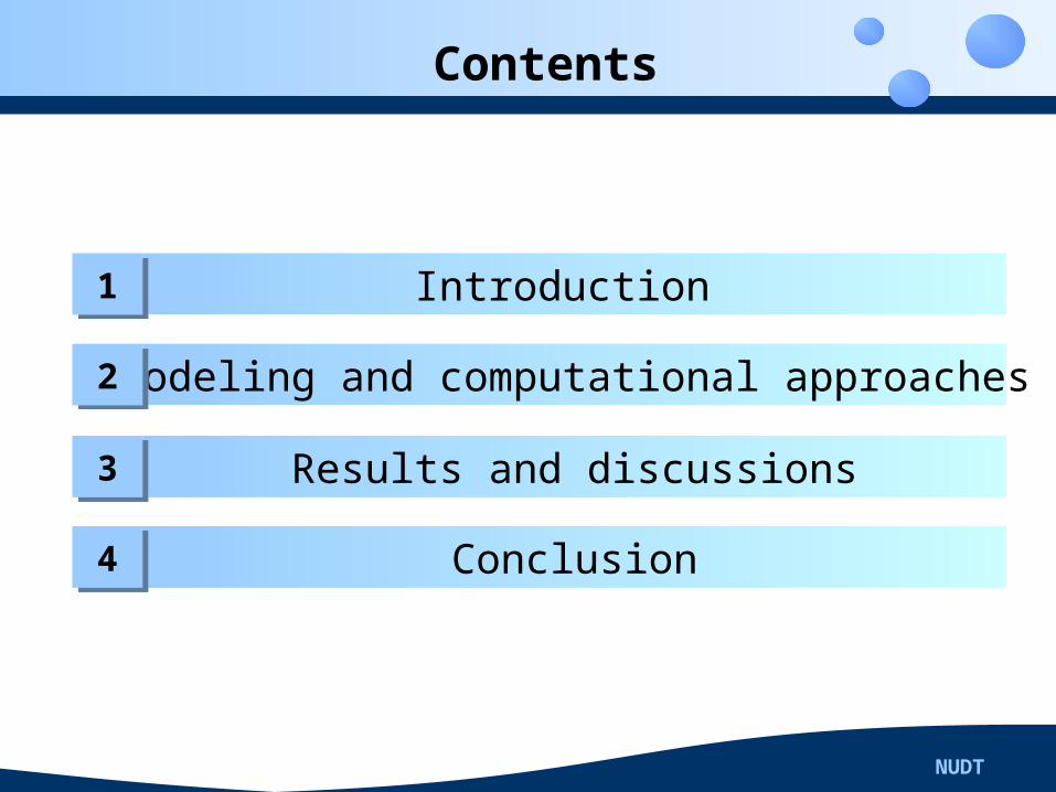
Supercavitation, which could decrease more than 90% of the
drag, is an outstanding method of anti-drag for high speed fully-
submerged vehicles. As a result, it has attracted more and more
interests resently.
Cavitator is an important facility of supercavitating vehicle, its
performance has a deep influence on cavitation effects and drag
of the vehicle.
NUDT
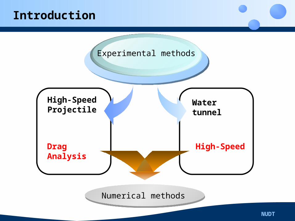
Introduction
High-Speed Projectile
Drag Analysis
Experimental methods
Water tunnel
High-Speed
Numerical methods
NUDT
Introduction
Singhal et.al established natural cavitating rate model based
on once order Rayleigh-Plesset equation, successfully simulated
the supercavity in comparison with the results of experiments.
Then, plenty of natural supercaviting simulations are carried out
based on the Singhal’s model. Especially, the model of Bakir et
al. was utilized by the generic CFD code ANSYS CFX, which is
the basement of this paper.
NUDT
Modeling and computational approaches
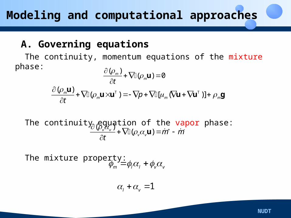
A. Governing equations The continuity, momentum equations of the mixture phase:
The continuity equation of the vapor phase:
The mixture property:
( )( ) 0m
mt
u
T T( )( ) [ ( )]m
m m mpt
u
u u u u g
( )( )v v
v v m mt
u
m l l v v
1l v
NUDT
Modeling and computational approaches
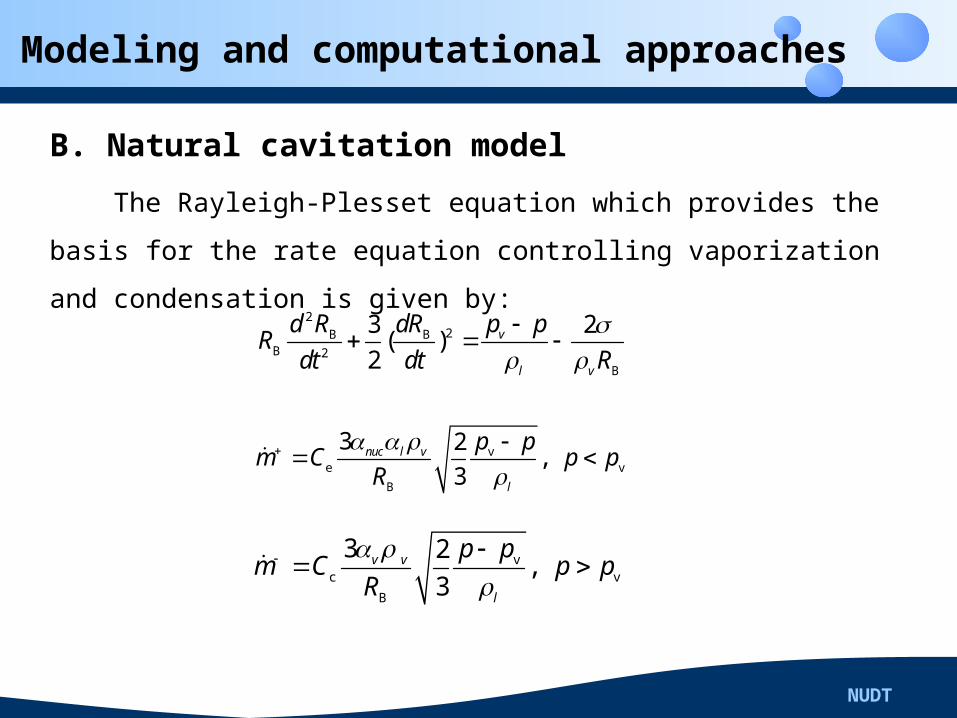
B. Natural cavitation model
The Rayleigh-Plesset equation which provides the basis for
the rate equation controlling vaporization and condensation is
given by:2
2B BB 2
B
3 2( )2
v
l v
p pd R dRR
dt dt R
ve v
B
3 2,
3nuc l v
l
p pm C p p
R
vc v
B
3 2,
3v v
l
p pm C p p
R
NUDT
Modeling and computational approaches
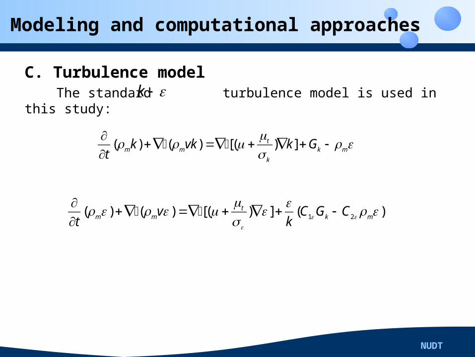
C. Turbulence model The standard turbulence model is used in this study:
( ) ( ) [( ) ]tm m k m
k
k vk k Gt
1 2( ) ( ) [( ) ] ( )tm m k mv C G C
t k
k
NUDT
Modeling and computational approaches
D. Computational approaches
The generic CFD code ANSYS CFX was utilized to investigate
the supercavitation flow. The governing equations discretized
by the Finite Volume Method(FVM). The convection terms were
approximated by a high order resolution scheme while the
diffusion terms were approximated by the second-order central
difference scheme.
NUDT
Results and discussions
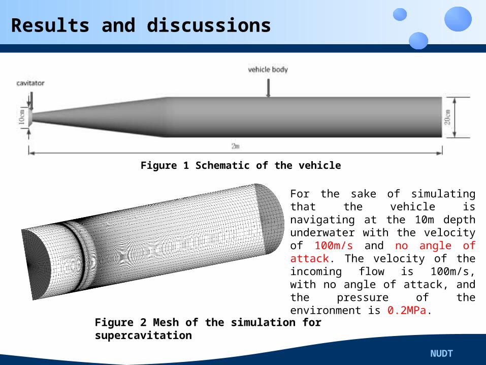
Figure 1 Schematic of the vehicle
Figure 2 Mesh of the simulation for supercavitation
For the sake of simulating that the vehicle is navigating at the 10m depth underwater with the velocity of 100m/s and no angle of attack. The velocity of the incoming flow is 100m/s, with no angle of attack, and the pressure of the environment is 0.2MPa.
NUDT
Results and discussions
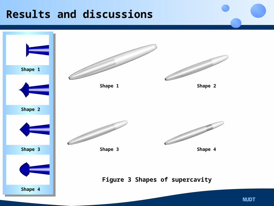
Figure 3 Shapes of supercavity
Shape 1
Shape 2
Shape 3
Shape 4
Shape 1 Shape 2
Shape 3 Shape 4
NUDT
Results and discussions
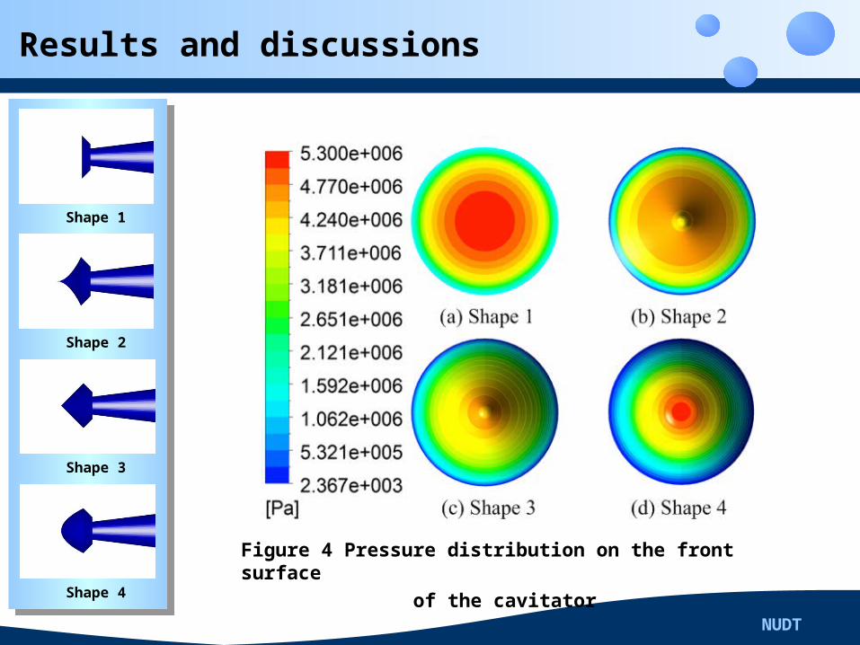
Figure 4 Pressure distribution on the front surface of the cavitator
Shape 1
Shape 2
Shape 3
Shape 4
NUDT
Results and discussions
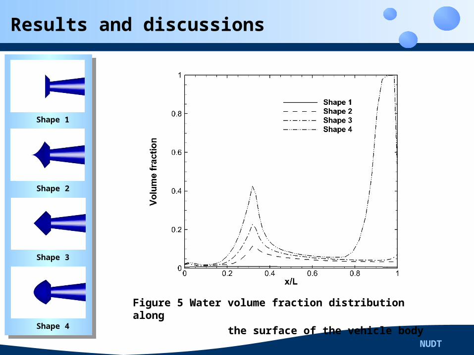
Figure 5 Water volume fraction distribution along the surface of the vehicle body
Shape 1
Shape 2
Shape 3
Shape 4
NUDT
Results and discussions
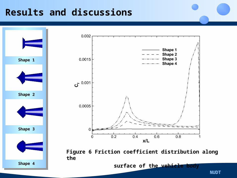
Figure 6 Friction coefficient distribution along the surface of the vehicle body
Shape 1
Shape 2
Shape 3
Shape 4
NUDT
Results and discussions
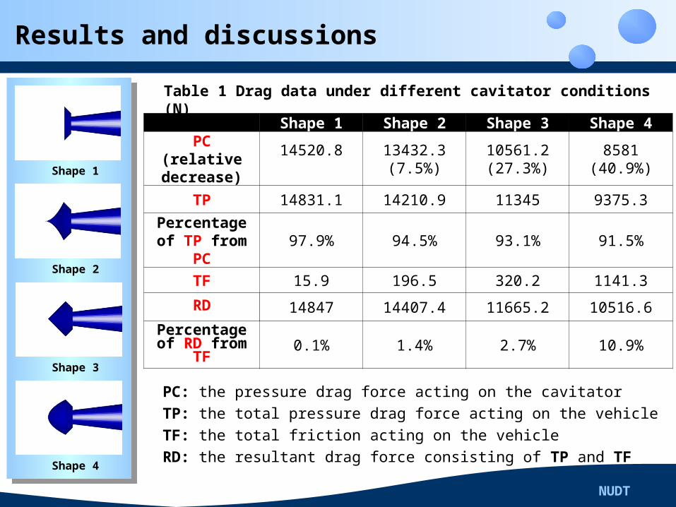
Table 1 Drag data under different cavitator conditions (N)
Shape 1
Shape 2
Shape 3
Shape 4
Shape 1 Shape 2 Shape 3 Shape 4PC
(relative decrease)
14520.8
13432.3(7.5%)
10561.2(27.3%)
8581(40.9%)
TP 14831.1 14210.9 11345 9375.3
Percentage of TP from
PC97.9% 94.5% 93.1% 91.5%
TF 15.9 196.5 320.2 1141.3
RD 14847 14407.4 11665.2 10516.6
Percentage of RD from
TF0.1% 1.4% 2.7% 10.9%
PC: the pressure drag force acting on the cavitatorTP: the total pressure drag force acting on the vehicleTF: the total friction acting on the vehicleRD: the resultant drag force consisting of TP and TF
NUDT
Conclusion
A.
Under the same conditions of diameter and income flow, disk
cavitator owns the highest cavitating capability, but the
pressure drag on cavitator is the largest of all. Convex conical
cavitator has a opposite performance, there is wet part at the
tail of the vehicle ,but the the pressure drag on cavitator
decrease 40.9% relatively. The other two perform between disk
cavitator and convex conical cavitator.
NUDT
Conclusion
B.
The pressure drag on cavitator is higher than 90 percents of
total pressure drag, indicating that the pressure drag on
cavitator is the key part of total pressure drag, it is significant to
reduce the total pressure drag through optimal design of the
shape of cavitator.
NUDT
Conclusion
C.
Good positive correlation is found between water volume
fraction and friction coefficient distribution along the surface of
vehicle body. If the surface touches water, the friction will jump
sharply, indicating that the cavitating method of anti-drag is
outstanding to reduce the friction of the underwater vehicle.
Thank you