Embed Size (px)
Citation preview
Numerical simulation of solar chimney integrated with exhaust of thermal power plant
H. H. Al-Kayiem1, K. Yin Yin2 & C. Yee Sing1 1Universiti Teknologi PETRONAS, Malaysia 2PETRONAS Carigali Sdn. Bhd., Malaysia
Abstract
The heat losses within exhaust gases are an unavoidable part of operating any fuel-fired system. The flue gases still hold considerable thermal energy, which is exhausted to the atmosphere as waste heat and contributes to global warming. This paper presents a developed technique to enhance the performance of low temperature solar thermal systems by utilization of thermal energy recovery of flue gases. A CFD model was established based on the energy, momentum and mass conservation and the state equation in 2-D, steady assumption with k-epsilon for the turbulence modelling using FLUENT – version 6.2.16 software. The model simulates the thermal and fluids flow processes in an inclined modified solar chimney. The flue inlet temperature was varied as, Tf g= 603K, 843K, and 983K. The simulation results were validated by comparison with experimental results obtained from a lab scale model, and acceptable agreement was gained. When the flue temperature is increased from 605K to 843K, the performance is enhanced by 75%. The interesting find is that the efficiency of heat collection tends to increase as the absorber length increases up to a certain length, and then starts to decrease. In this study, the suitable dimension for solar-flue gas collector is about 2.5 m. Keywords: solar chimney, numerical analysis, CFD, energy conversion, energy recovery, flue gases.
1 Introduction
The potential of solar chimney as an energy source to produce power has been widely researched and successfully demonstrated by numerous previous experimental studies. A solar chimney power plant is one of the proven
Advanced Computational Methods and Experiments in Heat Transfer XII 61
www.witpress.com, ISSN 1743-3533 (on-line) WIT Transactions on Engineering Sciences, Vol 7 , © 201 WIT Press2
doi:10.2495/HT120061
5
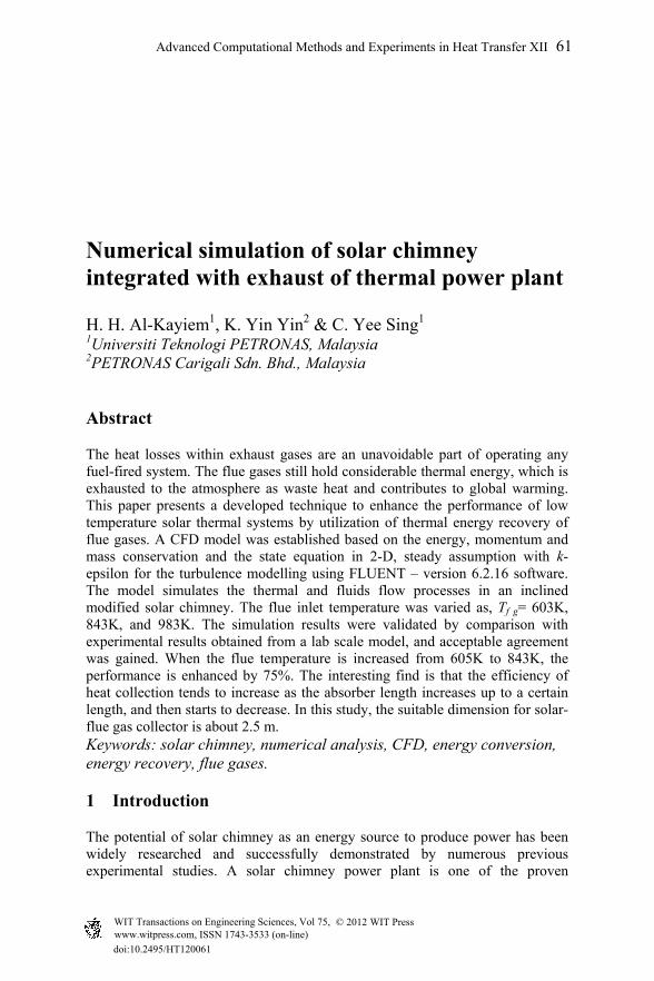
techniques to convert the solar radiation to electrical power. It has three core components – solar collector (made of absorbing medium covered by transparent cover), chimney and wind turbine, as schematized in Figure 1. As the sun heats up the air beneath the solar collector, a pressure gradient is induced causing a continuous flow of air as warmer air escapes the chimney and cooler air is drawn from the surrounding. The resulting air stream turns the wind turbine, which is installed near the base of the chimney. The kinetic energy of the rotating wind turbine is subsequently converted to electricity by an electric generator.
Figure 1: Schematic of a solar chimney power plant Al-Kayiem et al. [1] .
In 1981, the German structural engineering company, Schlaich Bergermann and Partners (SBP) proposed, designed, built, and tested a SCPP in Manzanares, Spain. The plant has a collector diameter of 240 m and a chimney of 195 m high with 10 m diameter. It is the largest constructed Solar Chimney Power Plant to date designed to produce 50kW electricity (Fluri [2]). After an experimental phase, the prototype plant fed the Spanish grid in fully automated operation from July 1986 to February 1989 during a total of 8611 hours (Schlaich [3]). As the operation of solar chimney power plant is dependent on solar radiation, the concept suffers a setback of non-productive periods at night and during cloudy days. Well-known solutions to this problem include the use of
Air flow
Solar radiation, Io
Wind stream
Wind turbine and generator unit
Chimney tower, Ht
Canopy height, δ
Transparent Canopy
Rc
( )
62 Advanced Computational Methods and Experiments in Heat Transfer XII
www.witpress.com, ISSN 1743-3533 (on-line) WIT Transactions on Engineering Sciences, Vol 75, © 201 WIT Press2
water storage. Kreetz [4] introduced the concept of water-filled tubes under the collector roof for thermal energy storage. Bernardes [5] investigated the possibility of using water-filled tubes on the collector floor as heat storage device and finds that its implementation smoothes out the daily fluctuation of power output and, hence, increases the power output after sunset and phase change materials (PCM) (Sharma et al. [6] and Kaneko et al. [7]). To this end, a novel technique has been proposed by utilizing flue gas produced from power plants, furnaces and other industrial plants to supplement the solar energy input to achieve uninterrupted power generation and to increase the power output of the solar chimney power plant. Encouraging results from the experimental study conducted by Al-Kayiem et al. [8] have demonstrated the feasibility of the concept. A comprehensive review on the enhancement techniques of the solar chimney power plants is reported by Chikere et al . [9] , who proposed modified version to the inclined solar-flue chimney proposed by [8]. Further development of the research may incorporate various strategies to scale up the model to plant prototype. This requires a deeper understanding of key contributing factors of the operation of the system. The aim of this paper is to develop a CFD simulation model of the flue gas solar chimney and to investigate the influence of three key factors to the performance of the system; the area of absorber plate and mass flow rate of flue gas, and the inlet temperature of the flue gases. The study was conducted by employing FLUENT software to model and simulate the hydro thermal process in the proposed system. The results are validated by comparing with the experimental measurements presented by [8].
2 Operational principles of solar-flue chimney
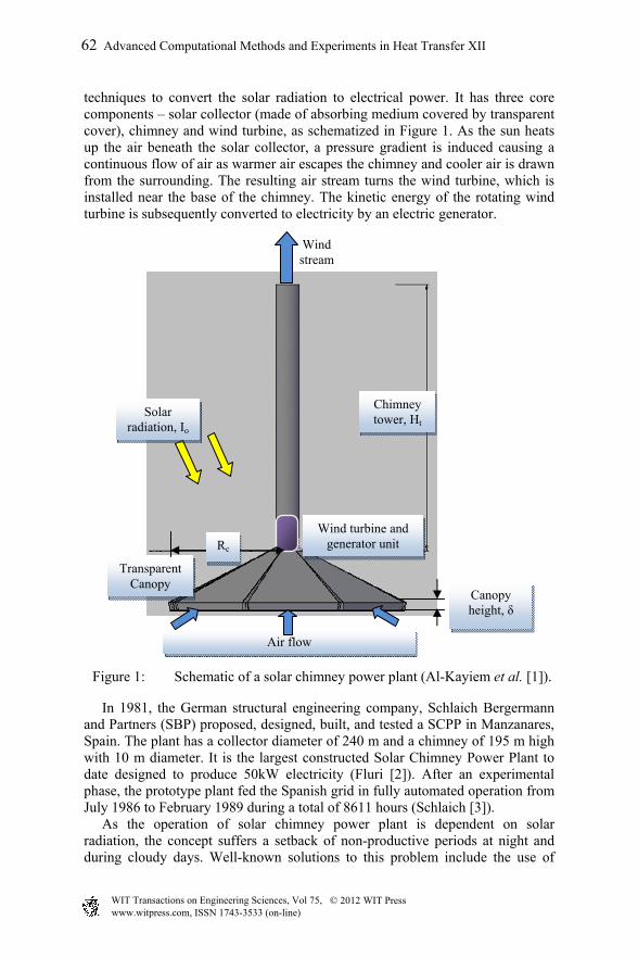
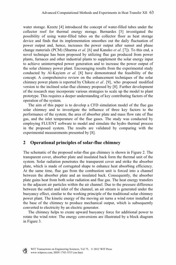
The schematic of the proposed solar-flue gas chimney is shown in Figure 2. The transparent cover, absorber plate and insulated back form the thermal unit of the system. Solar radiation penetrates the transparent cover and strike the absorber plate, which is made of corrugated shape to enhance heat absorbing efficiency. At the same time, flue gas from the combustion unit is forced into a channel between the absorber plate and an insulated back. Consequently, the absorber plate gains heat from both solar radiation and flue gas. The heat energy transfers to the adjacent air particles within the air channel. Due to the pressure difference between the outlet and inlet of the channel, an air stream is generated under the buoyancy effect, similar to the working principle of the traditional solar chimney power plant. The kinetic energy of the moving air turns a wind rotor installed at the base of the chimney to produce mechanical output, which is subsequently converted to electricity by an electric generator. The chimney helps to create upward buoyancy force for additional power to rotate the wind rotor. The energy conversions are illustrated by a block diagram in Figure 3.
Advanced Computational Methods and Experiments in Heat Transfer XII 63
www.witpress.com, ISSN 1743-3533 (on-line) WIT Transactions on Engineering Sciences, Vol 75, © 201 WIT Press2
Figure 2: Schematic of the solar-flue chimney power plant.
Figure 3: The energy conversion sequence in the solar chimney power plant.
3 Modelling criteria
To simulate the process of the fluid and heat flow, a model is constructed by GAMBIT software having air and flue flow panels and inlets and outlets, as shown in Figure 1. The case is simulated as steady, which is quite acceptable since the supplied flue from the thermal source is unchangeable, and 2-D, since the width to the height ration of the cross section in both the air and the flue channels as 1.0 m/0.05 m is quite high.
Solar radiation
Thermal energy from flue gas
Absorber Thermal energy
Air channel Conversion of thermal energy to Kinetic energy of air molecule
Wind turbine Conversion to mechanical energy
Generator Conversion to electrical power
Electricity
Wind Rotor casing
Air channel
Transparent cover
Absorber plate Flue gas channel
Insulated back
Flue outlet Warm air stream
Ambient air inlet
Flue gas inlet
64 Advanced Computational Methods and Experiments in Heat Transfer XII
www.witpress.com, ISSN 1743-3533 (on-line) WIT Transactions on Engineering Sciences, Vol 75, © 201 WIT Press2
3.1 Material selection
In the material selection, basic requirements such as functional requirements, process ability requirements, cost, reliability and resistance to service conditions must be met. In this project, the absorber plate is the main contribution to the heat transfer process; therefore, the material must have high thermal conductivity, adequate strength and good corrosion resistance. Copper is generally preferred because of its high thermal conductivity and resistance to corrosion. However, due to market availability and economic concern, aluminium is chosen to construct the absorber surface for this project. As for insulating material, it is used to reduce heat losses from the absorbing plate. The desired characteristics are low thermal conductivity, stability at high temperature, no degassing and ease of fabrication. On the other hand, the characteristic of the cover plate has to be able to transmit maximum solar energy to the absorbing plate, minimize upward heat loss from the absorbing plate to environment and to shield the absorber plate. The transmittance of glass depends on its iron content, which means lower the iron content has higher transmittance for solar radiation. Tempered glass is the most common cover material for solar collectors due to high durability and stability when exposed to UV radiation and has higher reduction on radiation. Besides, transparent plastic material such as acrylic polycarbonate plastic, plastic films of Tedlar and Mylar and commercial plastic such as Perspex and Lexan may also be used for cover plate. In terms of performance, it is less effective in reducing radiated heat losses from the absorbing plate and cannot withstand the stagnant temperatures encountered in hot environment. However, the main advantages of plastic materials are the cost, lightweight and resistance to breakage.
3.2 Boundary conditions
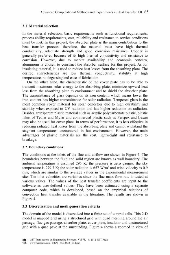
The conditions at the inlets of the flue and airflow are shown in Figure 4. The boundaries between the fluid and solid region are known as wall boundary. The ambient temperature is assumed 295 K; the pressure is zero gauges, the sky temperature is 279.7 K; the solar radiation is 657 W/m2 and wind velocity is 0.9 m/s, which are similar to the average values in the experimental measurement site. The inlet velocities are variables since the flue mass flow rate is tested at various values. The values of the heat transfer coefficients are input to the software as user-defined values. They have been estimated using a separate computer code, which is developed, based on the empirical relations of convection heat transfer available in the literature. The results are shown in Figure 4.
3.3 Discretization and mesh generation criteria
The domain of the model is discretized into a finite set of control cells. This 2-D model is mapped grid using a structured grid with quad meshing around the air passage, flue gas passage, absorber plate, cover plate, insulator and unstructured grid with a quad pave at the surrounding. Figure 4 shows a zoomed in view of
Advanced Computational Methods and Experiments in Heat Transfer XII 65
www.witpress.com, ISSN 1743-3533 (on-line) WIT Transactions on Engineering Sciences, Vol 75, © 201 WIT Press2
Figure 4: The boundary conditions of the model.
the computational grid across the fluid. The mesh in air passage is compressed towards the solid boundaries in order to accurately capture the flow distribution and temperature profile. Uniform grid was used to provide fine mesh resolution in regions where high gradients were expected. The model had 3280 cells in air passage, 1850 cells in flue gas passage and 48561 unstructured cells at the ambient condition. After few comparisons on the amount of grid cells, it has been shown that this number is low enough to provide quick computational turnaround, but was sufficiently high to provide a grid-insensitive solution. Before setting up boundary condition in FLUENT, the "2ddp" option is used to select the 2-dimensional, double-precision solver. However, the downside of using double precision is that it requires more memory. The model uses a segregated solver with implicit formulation. The momentum, continuity and energy equation are solved using the first order upwind scheme to get an approximate solution. Reynolds number suggests the flow is in the turbulent regime, therefore a standard k-epsilon with realizable model is used for the turbulence modeling with the turbulence equations being solved using the first order upwind scheme. This realizable k-epsilon model is
657 W/m2 from Solar
Radiation T sky = 279.7K h rad = 39.09 W/m2K
Convection T = 295K V wind = 0.9 m/s h wind = 5.5 W/m2K
Air inlet: T in = 295K V in = 1.21m/s h c,air = 20.61W/m2K h r,air = 10.79 W/m2K Insulated,
q=0
Flue gas inlet: T in = 603 K V in = 6.899 m/s hc, fg = 43.66 W/m2K h r,fg = 11.16 W/m2K mfg = 0.18 kg/s
Flue gas and Air outlet: Pgauge= 0 kPa Tatm = 295K emmisivity= 0.01
66 Advanced Computational Methods and Experiments in Heat Transfer XII
www.witpress.com, ISSN 1743-3533 (on-line) WIT Transactions on Engineering Sciences, Vol 75, © 201 WIT Press2
able to produces more accurate results for boundary layer flows than the Standard k-epsilon model. In addition, Enhanced Wall Treatment is chosen in order to deal with the resolution of the boundary layer in the model. P-1 radiation model is used for heat transfer simulation to study the effect of heating or cooling of surface due to radiation. P-1 model assumes that all surfaces are diffuse. This means that the reflection of incident radiation at the surface is isotropic with respect to the solid angle. The implementation assumes gray radiation.
4 Simulation criteria
The simulation is carried out by FLUENT version 6.2.16 assuming study, 2-D, and turbulent flow. Also, it is assumed that the thermal conductivity and the surface roughness of the metal surfaces are not changing with temperature. The working fluid; air is assumed compressible. The density at anywhere in the flow field is predicted by using the ideal fluid assumption utilizing the predicted pressure and temperature at that particular point. The set of the governing equations is shown from equation (1) to equation (9). The flue is assumed incompressible, while the air is compressible since the motion is due to the density change in the air channel. Hence: The continuity equations For air
0 (1)
For flue
0 (2)
The momentum equations for air in x and y are given by:
(3)
ρ ρ (4)
While the momentum equations for the flue gases in x and y are given by:
(5)
(6)
The energy equation is given by:
k k
τ τ (7)
Advanced Computational Methods and Experiments in Heat Transfer XII 67
www.witpress.com, ISSN 1743-3533 (on-line) WIT Transactions on Engineering Sciences, Vol 75, © 201 WIT Press2
And the differential forms of the state equation
(8)
In this model, two additional transport equations are being solved which are the turbulence kinetic energy, k and the turbulence dissipation rate, ε. The turbulence viscosity is then computed as a function of k and ε. The turbulent viscosity, µt is computed by combining k and ε as below:
(9)
where, Cµ is a constant recommended to be 0.09. The prediction is considered converged if the scaled residual for the continuity equation, the momentum equation, P-1 radiation, and the energy equation are less than 1x10⁻², 1x10⁻³, 1x10⁻⁴ and 1x10⁻⁷, respectively. In additional, a comparison between the results at 100 iterations and 500 iterations has proved that the solution at 100 iterations has converged.
5 Discussion of results
The simulation results are presented in forms of contours for the pressure and temperature, and in vector forms for the velocity and flow analysis. Also, some predicted values are presented in tabulation form for comparison between different design and operational parameters.
5.1 Validation of the simulation criteria
The predicted results from the simulation have been compared with the corresponding experimental results. The cases considered are with three different flue inlet temperatures, as shown in table 1.
Table 1: Validation of the simulation criteria by comparison with experimental results.
Boundary
conditions T flue in (K)
Results of air velocity at exit (m/s) Error
(%) Experiment (K) simulation
Flue mass flow
rate = 0.18 kg/s
603 2.17 2.36 8.7
843 4.41 4.95 12.2 983 5.24 5.86 11.8
The absolute percentage of error is around 10%. In all cases, the predicted values from the simulation are higher than the experimentally measured ones. The reason is due to the losses that takes place from the back and from the sides
68 Advanced Computational Methods and Experiments in Heat Transfer XII
www.witpress.com, ISSN 1743-3533 (on-line) WIT Transactions on Engineering Sciences, Vol 75, © 201 WIT Press2
of the fluid flow channels. Also, it may be due to the estimation of the convection heat transfer which is carried out separately assuming constant properties of fluids and materials. Within this range of error, the simulation results are considered acceptable and justified enough to study the effect of the other parameters, taking into consideration that this is a design project rather than investigation of the fluid and heat behavior in the system.
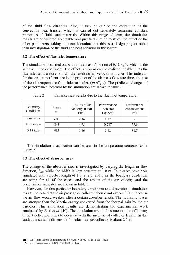
5.2 The effect of flue inlet temperature
The simulation is carried out with a flue mass flow rate of 0.18 kg/s, which is the same as in the experiment. The effect is clear as can be realized in table 1. As the flue inlet temperature is high, the resulting air velocity is higher. The indicator for the system performance is the product of the air mass flow rate times the rise of the air temperature from inlet to outlet, ( ∆ ). The predicted changes of the performance indicator by the simulation are shown in table 2.
Table 2: Enhancement results due to the flue inlet temperature.
Boundary conditions
T flue in
(K)
Results of air velocity at exit
(m/s)
Performance indicator (kg.K/s)
Performance enhancement
(%)
Flue mass
flow rate =
0.18 kg/s
603 2.36 0.07 -
843 4.95 0.287 75.6
983 5.86 0.62 88.7
The simulation visualization can be seen in the temperature contours, as in Figure 5.
5.3 The effect of absorber area
The change of the absorber area is investigated by varying the length in flow direction, Labs while the width is kept constant at 1.0 m. Four cases have been simulated with absorber length of 1.5, 2, 2.5, and 3 m. the boundary conditions are same for all of the cases, and the results of the air velocity and the performance indicator are shown in table 3. However, for this particular boundary conditions and dimensions, simulation results indicate that the air passage or collector should not exceed 3.0 m, because the air flow would weaken after a certain absorber length. The hydraulic losses are stronger than the kinetic energy converted from the thermal gain by the air particles. This simulation results are demonstrating the experimental work conducted by Zhai et al. [10]. The simulation results illustrate that the efficiency of heat collection tends to decrease with the increase of collector length. In this study, the suitable dimension for solar-flue gas collector is about 2.5m.
Advanced Computational Methods and Experiments in Heat Transfer XII 69
www.witpress.com, ISSN 1743-3533 (on-line) WIT Transactions on Engineering Sciences, Vol 75, © 201 WIT Press2
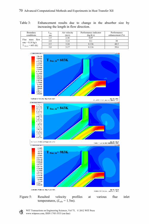
Table 3: Enhancement results due to change in the absorber size by increasing the length in flow direction.
Boundary conditions
Labs
(m) Air velocity
(m/s) Performance indicator
(kg.K/s) Performance
enhancement (%)
Flue mass flow rate = 0.18 kg/s T flue in = 603 (K)
1.5 2.36 0.07 -
2.0 3.14 0.1 30
2.5 3.24 0.136 48.5
3.0 3.17 0.116 39.6
Figure 5: Resulted velocity profiles at various flue inlet temperatures, (Labs = 1.5m).
T flue, in= 603K
T flue, in= 843K
T flue, in= 983K
70 Advanced Computational Methods and Experiments in Heat Transfer XII
www.witpress.com, ISSN 1743-3533 (on-line) WIT Transactions on Engineering Sciences, Vol 75, © 201 WIT Press2
6 Conclusions
Inclined solar chimney integrated with flue gas source is modeled and simulated to investigate the performance of the system at different absorber area and different supplied flue temperatures. The grid independency is checked and the simulation is validated by comparison with experimental measured on lab scale model. The mean error is about 10% between the predicted and measured velocities of air at outlet. When the flue temperature is increased from 605K to 843, the performance is enhanced by 75%, indicating that this is a highly effective parameter on the system performance. The simulation results illustrate that the efficiency of heat collection tends to increase as the absorber length increased up to a certain length, and then starts to decrease. In this study, the suitable dimension for solar-flue gas collector is about 2.5m.The simulation demonstrates that there are many rooms for improvement of the system which can be tested in further investigations, mainly, the flue mass flow rate and the size of the air inlet. The proposed technique, on one hand, enhances the performance of the solar chimney by continuous, non-interrupted electricity production during day and night. On the other hand, the thermal energy which transfers from the flue gases to the solar chimney would cause the flue temperature to be reduced, and in turn reduce the contribution on the global warming.
Acknowledgements
The authors acknowledge the ministry of electricity – Iraq for granting the research. Also, Universiti Teknologi PETRONAS is acknowledged for the financial and technical support to present and publish the paper.
References
[1] Al-Kayiem, Hussain H., Sing, Chin Yee, and Jia Lin, ‘Performance Influence of the Solar Chimney Power Plant by Variation of the Canopy and Tower Heights’ proceedings of the Asean Australian Engineering Congress (AAEC 2011), Kuching, Sarawak, Malaysia, 25-27 July, 2011.
[2] Fluri T. P., “Turbine Layout for and Optimization of Solar Chimney Power Conversion Units.” PhD Thesis Department of Mechanical and Mechatronic Engineering University of Stellenbosch, 2008.
[3] Schlaich, J., “The Solar Chimney - Electricity from the Sun.” Edition Axel Menges, 1995.
[4] Kreetz, H. “Theoretische Untersuchungen und Auslegung eines temporaren Wasserspeichers fur das Aufwindkraftwerk” Diploma thesis, Technical University Berlin, 1997.
[5] Bernardes, M.A.D.S. “Technical, Economical and Ecological Analysis of Solar Chimney Power Plants” Ph.D. Thesis, Universität Stuttgart. 2004.
[6] S.D. Sharma, H. Kotani, Y. Kaneko, T. Yamanaka, K. Sagara. Design, Development of a Solar Chimney with Built-in Latent Heat Storage
Advanced Computational Methods and Experiments in Heat Transfer XII 71
www.witpress.com, ISSN 1743-3533 (on-line) WIT Transactions on Engineering Sciences, Vol 75, © 201 WIT Press2
Material for Natural Ventilation. International J. of Green Energy, V 4, Issue 3. May 2007. pp. 313-324.
[7] Y. Kaneko, K. Sagara, T. Yamanaka, H. Kotani. Ventilation Performance of Solar Chimney with Built-In Latent Heat Storage. Proceedings of International Conf. on Thermal Energy Storage, (ECOSTOCK), 2006
[8] Al-Kayiem, H. Hussain, How M. G., and Seow L. L., “Experimental Investigation on Solar-Flue gas Chimney,” Journal of Energy and Power Engineering. USA, vol 3 (9), pp 25-31, Sep. 2009.
[9] Chikere, Aja Ogboo, Al-Kayiem, Hussain H., and Zainal Ambri Abdul Karim, Review on the Enhancement Techniques and Introduction of an Alternate Enhancement Technique of Solar Chimney Power Plant, Journal of Applied Sciences 11 (11) (2011), pp. 1877-1884 DOI: 10.3923/jas2011.1877.1884.
[10] Zhai, X.Q.; Wang, R.Z.; Wu, J.Y.; Dai, Y.J.; Ma, Q., Design and performance of a solar-powered air-conditioning system in a green building Applied energy, May 2008, Volume 85, Issue 5, Pages 297-311. DOI:10.1016/j.apenergy.2007.07.01
72 Advanced Computational Methods and Experiments in Heat Transfer XII
www.witpress.com, ISSN 1743-3533 (on-line) WIT Transactions on Engineering Sciences, Vol 75, © 201 WIT Press2


![Improvement of thermal performance of a solar chimney based on a passive solar … · 2020-01-02 · solar chimney. Amongst them, the PCM-based solar chimney [8] has also been considered](https://img.pdfslide.us/doc/110x75/5e5a5015c4c7cf5c163eb194/improvement-of-thermal-performance-of-a-solar-chimney-based-on-a-passive-solar-2020-01-02.jpg)