Embed Size (px)
Citation preview
9191
Li Guomei1, 2, Wang Yueshe1*, He Renyang2, Cao Xuewen3, Lin Changzhi4 and Meng Tao2
1 State Key Laboratory of Multiphase Flow in Power Engineering, Xi’an Jiaotong University, Xi’an, Shaanxi 710049, China 2 China Special Equipment Inspection and Research Institute, Beijing 100013, China3 School of Transport & Storage and Civil Engineering, China University of Petroleum, Qingdao, Shandong 266555, China4 Petroleum Exploration and Production Research Institute, Sinopec, Beijing 100083, China
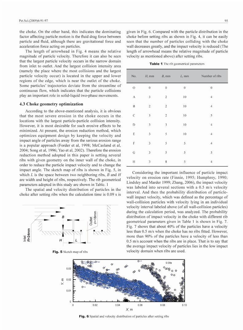
Abstract: Chokes are one of the most important components of downhole fl ow-control equipment. The particle erosion mathematical model, which considers particle-particle interaction, was established and used to simulate solid particle movement as well as particle erosion characteristics of the solid-liquid two-phase fl ow in a choke. The corresponding erosion reduction approach by setting ribs on the inner wall of the choke was advanced. This mathematical model includes three parts: the fl ow fi eld simulation of the continuous carrier fluid by an Eulerian approach, the particle interaction simulation using the discrete particle hard sphere model by a Lagrangian approach and calculation of erosion rate using semi-empirical correlations. The results show that particles accumulated in a narrow region from inlet to outlet of the choke and the dominating factor affecting particle motion is the fl uid drag force. As a result, the optimization of rib geometrical parameters indicates that good anti-erosion performance can be achieved by four ribs, each of them with a height (H) of 3 mm and a width (B) of 5 mm equaling the interval between ribs (L).
Key words: Solid-liquid two-phase fl ow, discrete particle hard sphere model, choke, erosion rate, anti-erosion, numerical simulation
1 IntroductionThe mechanical damage to the surface caused by the
impact of solid particles has been a serious problem in a variety of engineering applications. Any industrial process involving the transportation of solid particles entrained in the fl uid phase can be subject to erosion damage (Humphrey, 1990; Finnie, 1995). In oil and gas production, the solid particles, which were used as proppants and carried by fracturing fluids with a high velocity in sand fracturing operations, can cause serious damage to downhole flow-control equipment (chokes) as well as the surface of casing walls (Economides and Nolte, 2002; McCasland et al, 2004; Vincent et al, 2004). During oil-field water injection operations, particles entrained in continuous fluids can also cause damage to the casing wall (Jordan, 1998; Richardson et al, 1986). Depending on the actual conditions, the erosion damage may be severe and extremely expensive, as it may be frequently necessary to replace or repair the device or component that is exposed and susceptible to the erosive environment (McCasland et al, 2004; Jordan 1998; McLaury
et al, 1996; Wallace et al, 2004). Hence, it becomes more and more important to predict the erosion caused by particle impact accurately and to develop corresponding erosion reduction methods.
Computational Fluid Dynamics (CFD) has been used in the research on solid particle erosion for many years. CFD-based erosion prediction process includes several different aspects (Zhang, 2006): flow modeling, particle-fluid interaction, particle-particle interaction, particle-wall interaction and particle erosion modeling. Each aspect by itself is very complex, and many researchers have made great efforts in order to better understand the mechanisms. The current erosion computational models are established based on different mechanisms, which show satisfactory application to predicting particle movement characteristics, calculating the erosion rate of wall surfaces and improving particle tracking in order to reduce erosion (Chen et al, 2006; Fan et al, 2004; Forder et al, 1998; Habib and Badr, 2004; McCasland et al, 2004; McLaury and Wang 1997; Song et al, 1996; Yao et al, 2002). However, most of these models neglect the infl uence of particle movement on the fl uid as well as particle-particle interactions. These are one-way coupling methods and only applicable to the conditions of low volume fraction of the discrete particle phase. The four-way coupling
* Corresponding author. email: [email protected] August 25, 2008
DOI 10.1007/s12182-009-0017-9
Numerical simulation of predicting and reducing solid particle erosion of solid-liquid two-phase fl ow in a choke
Pet.Sci.(2009)6:91-97
92
2.2.2 Fluid drag forceThe coupling action between fluid and particle can be
expressed through the fl uid drag force Fdrag of an individual particle. Using the modifi ed fl uid drag force correlation (Di Felice, 1994), the fl uid drag force can be described as follows:
computational model (Elghobashi, 1994), which takes particle-fl uid interaction and particle-particle interaction into consideration at the same time, has been rarely reported in the literature, especially in the study of erosion of well pipeline systems.
The purpose of this paper is to provide deeper understanding of solid particle erosion characteristics in the choke and to change the fl ow fi eld geometry in order to reduce erosion. In this paper, the discrete particle hard sphere model was used to simulate particle-particle interaction; after obtaining information on particle movement (impact velocity and impact angle), the semi-empirical correlations were used to calculate particle erosion rate. Fortunately, this model not only takes particle-fluid interaction into consideration but particle-particle interaction as well, and is a four-way coupling method. Therefore, this model avoids the shortcomings of former models mentioned above and is applicable to the case of high volume fractions of the particle phase.
2 Mathematical modelThe mathematical model includes the following three
parts, namely the continuous carrier fl uid fl ow fi eld simulation by an Eulerian approach, particle-particle interaction simulation using a discrete particle hard sphere model by a Lagrangian approach, and erosion calculation using semi-empirical correlations.
2.1 Governing equations of continuous fl owThe equations of continuous flow are derived from the
volume averaged Navier-Stokes equations, which take into account the infl uence of fl uid volume fraction and drag force between the fluid and particle phases. The continuity and momentum equations are expressed as follows:
(1)
(2)
where , and p are the fl uid density, velocity, and pressure, respectively; g is gravity acceleration; is the fluid shear stress; is the volume fraction of fl uid; and fdrag is volumetric fl uid-particle interaction force, which can be given as:
(3)
(4)
where ∆V and Vpi are the volume of a computational cell and the volume of particle i inside this cell, respectively; Fdrag is the fl uid drag force for an individual particle; n is the number of particles in the cell.
The fl ow is turbulent, and the fl uid turbulence is treated with the standard turbulent model.
2.2 Discrete particle hard sphere model2.2.1 Inter-particle collision model
Inter-particle collision is described by a hard sphere model. The hard sphere model is based on binary quasi-instantaneous collisions. It neglects particle deformation during collision, resulting in a high calculation efficiency (Crowe et al, 1998).
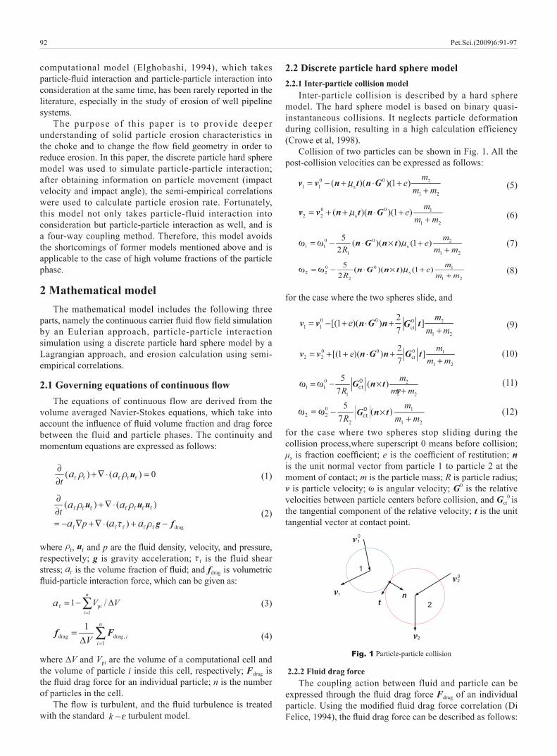
Collision of two particles can be shown in Fig. 1. All the post-collision velocities can be expressed as follows:
(5)
(6)
(7)
(8)
for the case where the two spheres slide, and
(9)
(10)
(11)
(12)
for the case where two spheres stop sliding during the collision process,where superscript 0 means before collision; μs is fraction coeffi cient; e is the coeffi cient of restitution; n is the unit normal vector from particle 1 to particle 2 at the moment of contact; m is the particle mass; R is particle radius; v is particle velocity; is angular velocity; G0 is the relative velocities between particle centers before collision, and Gct
0 is
the tangential component of the relative velocity; t is the unit tangential vector at contact point.
Fig. 1 Particle-particle collision
1
2t
0
0
1
1
2
2
n
Pet.Sci.(2009)6:91-97
v
93
(13)
with
where dp is the particle diameter; uf is the fl uid velocity; up is the particle velocity; Cd0 and Rep are the fl uid drag coeffi cient and particle Reynolds number, respectively, and they can be expressed as follows:
2.4 Criterion for occurrence of collision of two particles in the hard sphere model
In the hard sphere model system, the initiative search approach is used to judge the binary collisions. It is supposed that the two particles i and j happen to collide after the time ∆tc, so Rij=rij+vij∆tc, as a result ∆tc can be calculated with the following expression (Kang and Guo, 2006):
(9)
with
where r is the location vector of particles.If ∆tc<0 or if rij
.vij>0, the two particles will not collide.
3 Phys i ca l prob lem and s imula t ion conditions
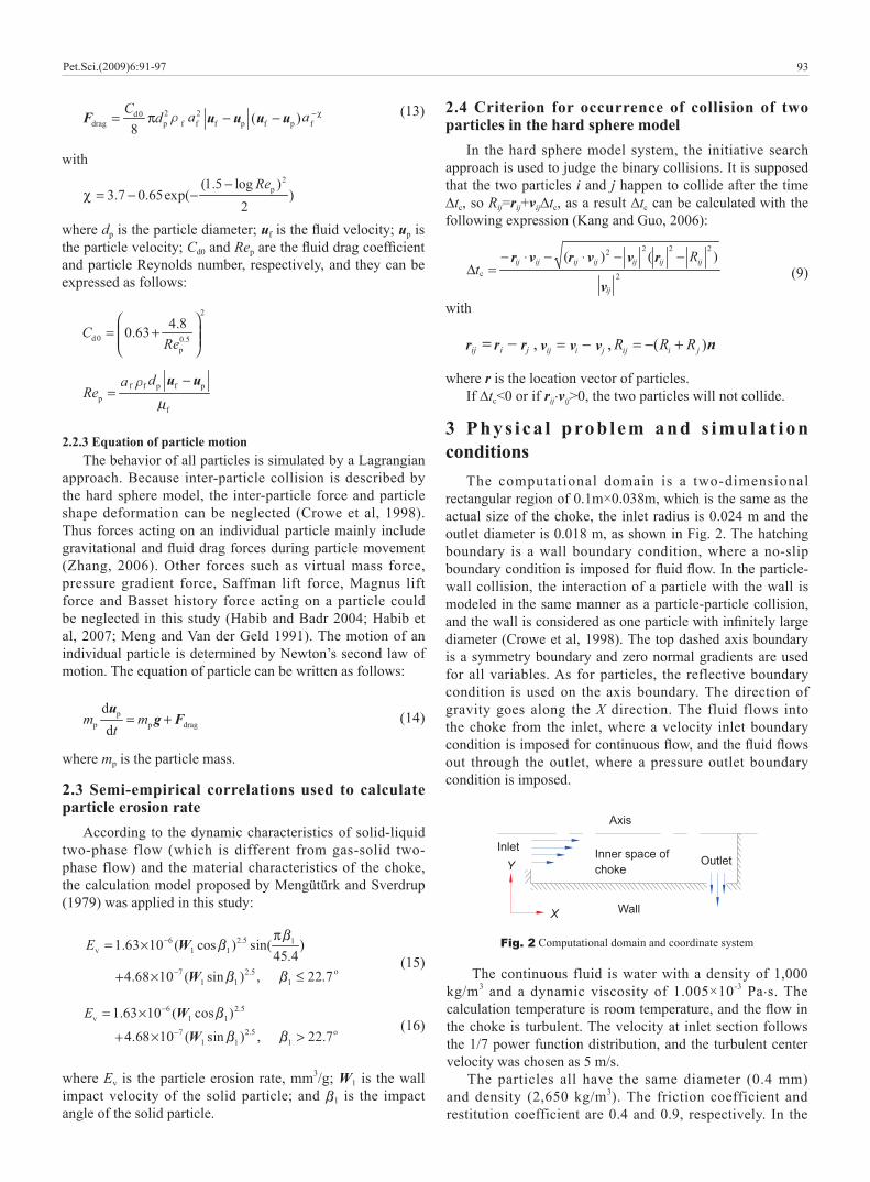
The computational domain is a two-dimensional rectangular region of 0.1m×0.038m, which is the same as the actual size of the choke, the inlet radius is 0.024 m and the outlet diameter is 0.018 m, as shown in Fig. 2. The hatching boundary is a wall boundary condition, where a no-slip boundary condition is imposed for fl uid fl ow. In the particle-wall collision, the interaction of a particle with the wall is modeled in the same manner as a particle-particle collision, and the wall is considered as one particle with infi nitely large diameter (Crowe et al, 1998). The top dashed axis boundary is a symmetry boundary and zero normal gradients are used for all variables. As for particles, the reflective boundary condition is used on the axis boundary. The direction of gravity goes along the X direction. The fluid flows into the choke from the inlet, where a velocity inlet boundary condition is imposed for continuous fl ow, and the fl uid fl ows out through the outlet, where a pressure outlet boundary condition is imposed.
2.2.3 Equation of particle motionThe behavior of all particles is simulated by a Lagrangian
approach. Because inter-particle collision is described by the hard sphere model, the inter-particle force and particle shape deformation can be neglected (Crowe et al, 1998). Thus forces acting on an individual particle mainly include gravitational and fl uid drag forces during particle movement (Zhang, 2006). Other forces such as virtual mass force, pressure gradient force, Saffman lift force, Magnus lift force and Basset history force acting on a particle could be neglected in this study (Habib and Badr 2004; Habib et al, 2007; Meng and Van der Geld 1991). The motion of an individual particle is determined by Newton’s second law of motion. The equation of particle can be written as follows:
(14)
where mp is the particle mass.
2.3 Semi-empirical correlations used to calculate particle erosion rate
According to the dynamic characteristics of solid-liquid two-phase flow (which is different from gas-solid two-phase flow) and the material characteristics of the choke, the calculation model proposed by Mengütürk and Sverdrup (1979) was applied in this study:
(15)
(16)
where Ev is the particle erosion rate, mm3/g; W1 is the wall impact velocity of the solid particle; and 1 is the impact angle of the solid particle.
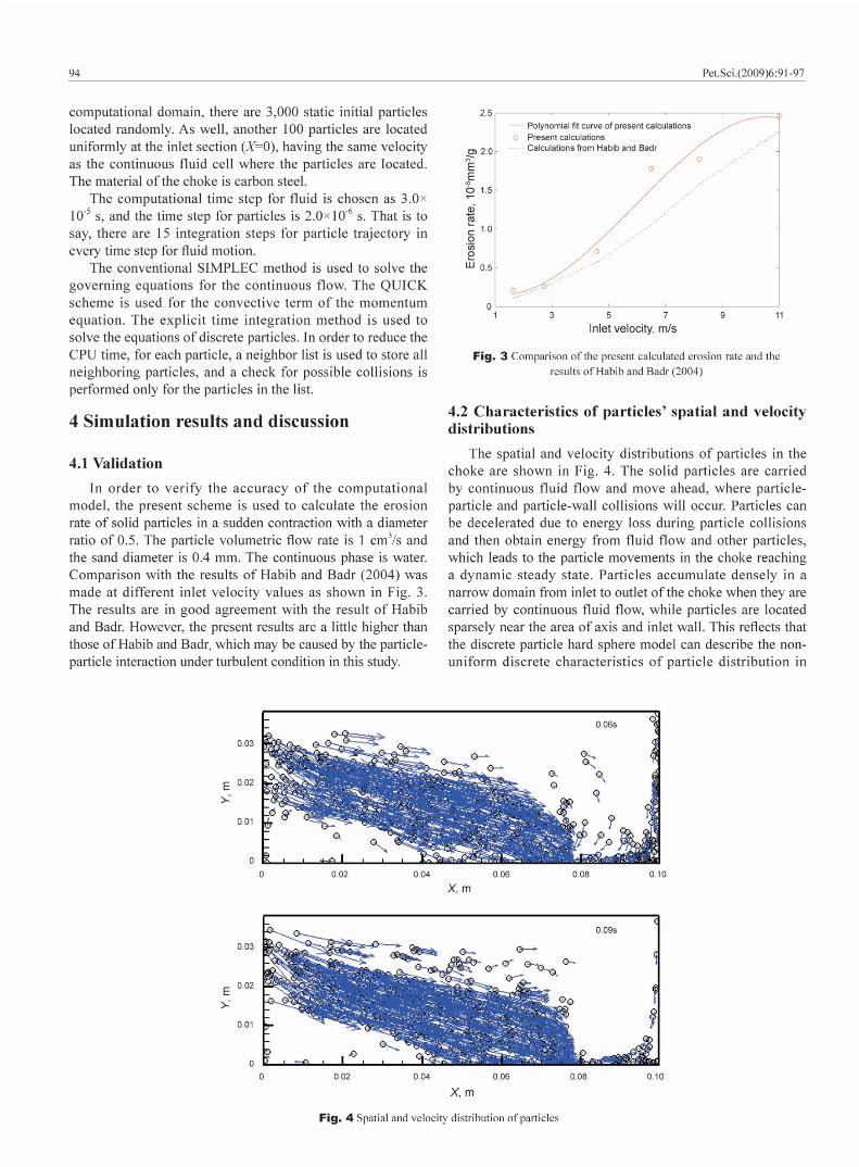
The continuous fluid is water with a density of 1,000 kg/m3 and a dynamic viscosity of 1.005×10⁻³ Pa.s. The calculation temperature is room temperature, and the fl ow in the choke is turbulent. The velocity at inlet section follows the 1/7 power function distribution, and the turbulent center velocity was chosen as 5 m/s.
The particles all have the same diameter (0.4 mm) and density (2,650 kg/m3). The friction coefficient and restitution coefficient are 0.4 and 0.9, respectively. In the
Fig. 2 Computational domain and coordinate system
Axis
InletOutlet
Inner space of choke
X
Y
Wall
Pet.Sci.(2009)6:91-97
96
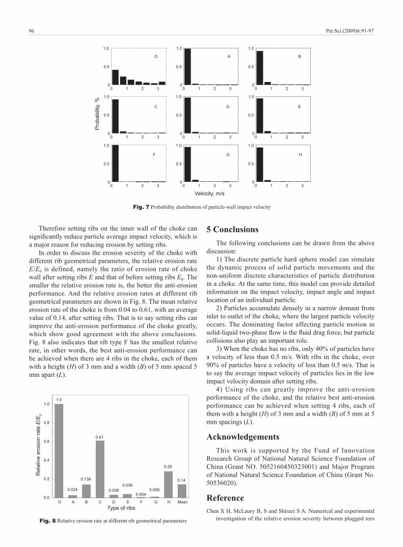
Fig. 7 Probability distribution of particle-wall impact velocity
0 1 2 30
0.5
1.0
0 1 2 30
0.5
1.0
0 1 2 30
0.5
1.0
0 1 2 30
0.5
1.0
0 1 2 30
0.5
1.0
0 1 2 30
0.5
1.0
0 1 2 30
0.5
1.0
0 1 2 30
0.5
1.0
0 1 2 30
0.5
1.0
O A B
C D E
F G H
Pro
babi
lity,
%
Velocity, m/s
Therefore setting ribs on the inner wall of the choke can signifi cantly reduce particle average impact velocity, which is a major reason for reducing erosion by setting ribs.
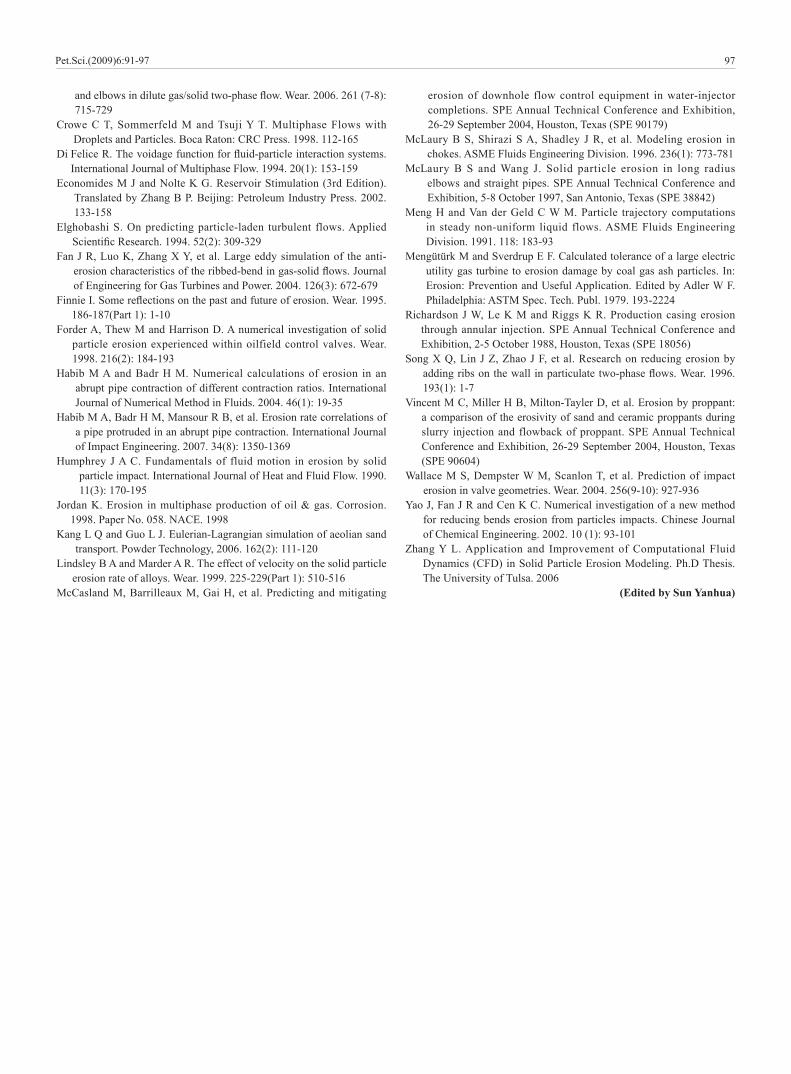
In order to discuss the erosion severity of the choke with different rib geometrical parameters, the relative erosion rate E/E0 is defined, namely the ratio of erosion rate of choke wall after setting ribs E and that of before setting ribs E0. The smaller the relative erosion rate is, the better the anti-erosion performance. And the relative erosion rates at different rib geometrical parameters are shown in Fig. 8. The mean relative erosion rate of the choke is from 0.04 to 0.61, with an average value of 0.14, after setting ribs. That is to say setting ribs can improve the anti-erosion performance of the choke greatly, which show good agreement with the above conclusions. Fig. 8 also indicates that rib type F has the smallest relative rate, in other words, the best anti-erosion performance can be achieved when there are 4 ribs in the choke, each of them with a height (H) of 3 mm and a width (B) of 5 mm spaced 5 mm apart (L).
5 ConclusionsThe following conclusions can be drawn from the above
discussion:1) The discrete particle hard sphere model can simulate
the dynamic process of solid particle movements and the non-uniform discrete characteristics of particle distribution in a choke. At the same time, this model can provide detailed information on the impact velocity, impact angle and impact location of an individual particle.
2) Particles accumulate densely in a narrow domain from inlet to outlet of the choke, where the largest particle velocity occurs. The dominating factor affecting particle motion in solid-liquid two-phase fl ow is the fl uid drag force, but particle collisions also play an important role.
3) When the choke has no ribs, only 40% of particles have a velocity of less than 0.5 m/s. With ribs in the choke, over 90% of particles have a velocity of less than 0.5 m/s. That is to say the average impact velocity of particles lies in the low impact velocity domain after setting ribs.
4) Using ribs can greatly improve the anti-erosion performance of the choke, and the relative best anti-erosion performance can be achieved when setting 4 ribs, each of them with a height (H) of 3 mm and a width (B) of 5 mm at 5 mm spacings (L).
AcknowledgementsThis work is supported by the Fund of Innovation
Research Group of National Natural Science Foundation of China (Grant NO. 5052160450323001) and Major Program of National Natural Science Foundation of China (Grant No. 50536020).
ReferenceChe n X H, McLaury B, S and Shirazi S A. Numerical and experimental
investigation of the relative erosion severity between plugged tees Fig. 8 Relative erosion rate at different rib geometrical parameters
0.0
0.2
0.4
0.6
0.8
1.0
0.14
0.28
0.0080.004
0.0360.028
0.61
0.138
Rel
ativ
e er
osio
n ra
te E
/E0
Type of ribs
1.0
0.024
MeanHGFEDCBAO
Pet.Sci.(2009)6:91-97
97
and elbows in dilute gas/solid two-phase fl ow. Wear. 2006. 261 (7-8): 715-729
Cro we C T, Sommerfeld M and Tsuji Y T. Multiphase Flows with Droplets and Particles. Boca Raton: CRC Press. 1998. 112-165
Di Felice R. The voidage function for fl uid-particle interaction systems. International Journal of Multiphase Flow. 1994. 20(1): 153-159
Eco nomides M J and Nolte K G. Reservoir Stimulation (3rd Edition). Translated by Zhang B P. Beijing: Petroleum Industry Press. 2002. 133-158
Elg hobashi S. On predicting particle-laden turbulent flows. Applied Scientifi c Research. 1994. 52(2): 309-329
Fan J R, Luo K, Zhang X Y, et al. Large eddy simulation of the anti-erosion characteristics of the ribbed-bend in gas-solid fl ows. Journal of Engineering for Gas Turbines and Power. 2004. 126(3): 672-679
Fin nie I. Some refl ections on the past and future of erosion. Wear. 1995. 186-187(Part 1): 1-10
For der A, Thew M and Harrison D. A numerical investigation of solid particle erosion experienced within oilfield control valves. Wear. 1998. 216(2): 184-193
Hab ib M A and Badr H M. Numerical calculations of erosion in an abrupt pipe contraction of different contraction ratios. International Journal of Numerical Method in Fluids. 2004. 46(1): 19-35
Hab ib M A, Badr H M, Mansour R B, et al. Erosion rate correlations of a pipe protruded in an abrupt pipe contraction. International Journal of Impact Engineering. 2007. 34(8): 1350-1369
Hum phrey J A C. Fundamentals of fluid motion in erosion by solid particle impact. International Journal of Heat and Fluid Flow. 1990. 11(3): 170-195
Jor dan K. Erosion in multiphase production of oil & gas. Corrosion. 1998. Paper No. 058. NACE. 1998
Kan g L Q and Guo L J. Eulerian-Lagrangian simulation of aeolian sand transport. Powder Technology, 2006. 162(2): 111-120
Lin dsley B A and Marder A R. The effect of velocity on the solid particle erosion rate of alloys. Wear. 1999. 225-229(Part 1): 510-516
McC asland M, Barrilleaux M, Gai H, et al. Predicting and mitigating
erosion of downhole flow control equipment in water-injector completions. SPE Annual Technical Conference and Exhibition, 26-29 September 2004, Houston, Texas (SPE 90179)
McL aury B S, Shirazi S A, Shadley J R, et al. Modeling erosion in chokes. ASME Fluids Engineering Division. 1996. 236(1): 773-781
McL aury B S and Wang J. Solid particle erosion in long radius elbows and straight pipes. SPE Annual Technical Conference and Exhibition, 5-8 October 1997, San Antonio, Texas (SPE 38842)
Men g H and Van der Geld C W M. Particle trajectory computations in steady non-uniform liquid flows. ASME Fluids Engineering Division. 1991. 118: 183-93
Men gütürk M and Sverdrup E F. Calculated tolerance of a large electric utility gas turbine to erosion damage by coal gas ash particles. In: Erosion: Prevention and Useful Application. Edited by Adler W F. Philadelphia: ASTM Spec. Tech. Publ. 1979. 193-2224
Ric hardson J W, Le K M and Riggs K R. Production casing erosion through annular injection. SPE Annual Technical Conference and Exhibition, 2-5 October 1988, Houston, Texas (SPE 18056)
Son g X Q, Lin J Z, Zhao J F, et al. Research on reducing erosion by adding ribs on the wall in particulate two-phase fl ows. Wear. 1996. 193(1): 1-7
Vin cent M C, Miller H B, Milton-Tayler D, et al. Erosion by proppant: a comparison of the erosivity of sand and ceramic proppants during slurry injection and flowback of proppant. SPE Annual Technical Conference and Exhibition, 26-29 September 2004, Houston, Texas (SPE 90604)
Wal lace M S, Dempster W M, Scanlon T, et al. Prediction of impact erosion in valve geometries. Wear. 2004. 256(9-10): 927-936
Yao J, Fan J R and Cen K C. Numerical investigation of a new method for reducing bends erosion from particles impacts. Chinese Journal of Chemical Engineering. 2002. 10 (1): 93-101
Zha ng Y L. Application and Improvement of Computational Fluid Dynamics (CFD) in Solid Particle Erosion Modeling. Ph.D Thesis. The University of Tulsa. 2006
(Edited by Sun Yanhua)
Pet.Sci.(2009)6:91-97