Embed Size (px)
Citation preview

Special ReviewMay 2008
99
Numerical simulation and optimization of Al alloy cylinder body by low pressure die casting
*Mi Guofa, Liu Yanlei, Zhao Hengtao, Fu Hengzhi(School of Materials Science and Engineering, Henan Polytechnic University, Jiaozuo 454000, China)
Abstract: Shrinkage defects can be formed easily at critical location during low pressure die casting (LPDC) of aluminum alloy cylinder body. It has harmful effect on the products. Mold fi lling and solidifi cation process of a cylinder body was simulated by using of Z-CAST software. The casting method was improved based on the simulation results. In order to create effective feeding passage, the structure of casting was modifi ed by changing the location of strengthening ribs at the bottom, without causing any adverse effect on the part’s performance. Inserting copper billet at suitable location of the die is a valid way to create suitable solidifi cation sequence that is benefi cial to the feeding. Using these methods, the shrinkage defect was completely eliminated at the critical location.
Key words: aluminum alloy; cylinder body; numerical simulation; optimizationCLC Number: Document Code: A Article ID: 1672-6421(2008)04-0099-05
In recent years, precision casting technology is favored by corporations for its less processing procedures, low cost and
short production period [1-5]. In LPDC, casting solidification under pressure is benefi cial to the mold fi lling; leak tightness and pressure resistance of the casting are both promoted by the homogeneous microstructure and less segregation. So these castings are widely used nowadays [6-7].
E80 cylinder body is the shell of certain special electrical engine. Excellent leak tightness and pressure resistance are required and shrinkage is not allowed in critical location. The casting was prepared by LPDC; the casting material is ZL102 alloy which has good thermal conductivity and high specifi c strength. A home-made Al-alloy coating material was painted on the mold’s inner surface. The cylinder body has a minimum of 4 mm and a maximum wall thickness of 38 mm. Owing to irregular outline dimensions and complex inner structure, shrinkage will be generated during solidification process, and thus reduced the overall yield greatly. Z-CAST software was used to simulate the mold filling and solidification of the casting. Casting method was optimized based on the simulation results in order to get rid of casting defect.
1 Initial conditions and boundary conditions
The cylinder body casting is shown in Fig.1. The 3-D geometry models were established according to casting design
Male, born in 1966, professor, Ph.D. Research interest: metal solidifacation technology and new materials.E-mail: [email protected]: 2008-02-29; Accepted: 2008-04-20
*Mi Guofa
Fig. 1 Cylinder body casting
and saved as *.STL format. Then the 3-D models (STLformat) were imported into Z-CAST software. The importing sequence is: cylinder body – chills – moulds. The imported geometry solids are shown in Fig. 2.
The mesh was generated according to two principles: (a) In order to avoid generating point contact in the thinnest
position, the step size should be less than 2 mm. (b) When using Z-CAST software for simulation calculation,
each mesh occupies 80 byte physical memory. So it should be assured that the number of mesh × 80 is
less than the memory of computer used. In the experiment, the service computer has a 1G memory. The dimension of the cylinder body is 362 mm × 300 mm × 342 mm (Lx × Ly × Lz). The step size was set as 2 mm and the total number of mesh was 4,642,650.
CHINA FOUNDRY Vol.5 No.2
100
(a) Velocity fi eld of 10% (b) Velocity fi eld of 30% (c) Velocity fi eld of 50%
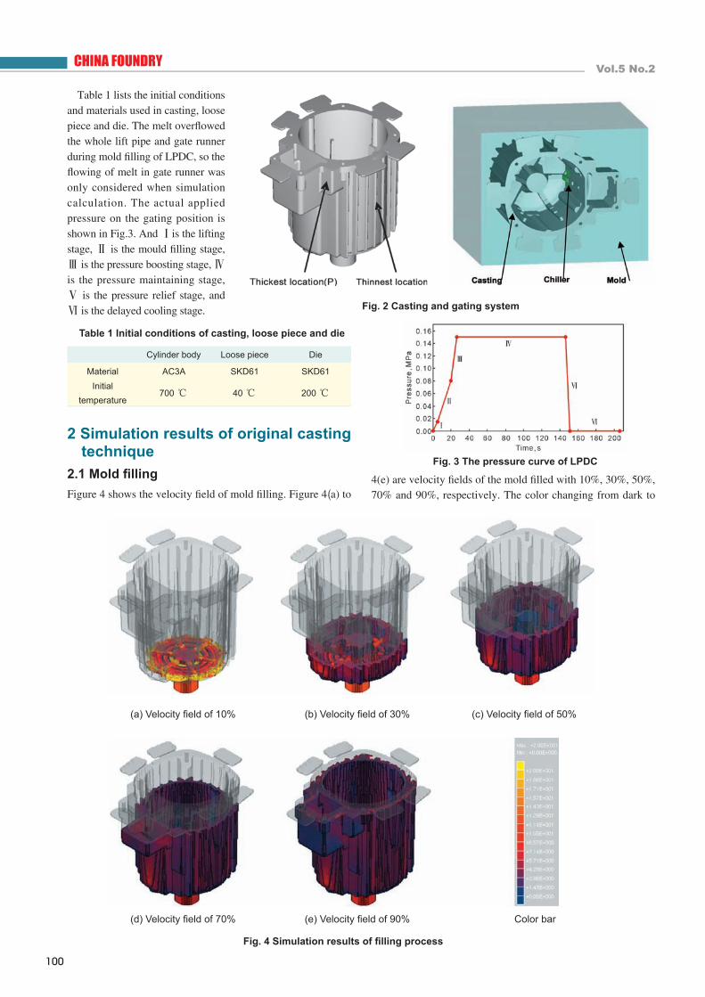
Table 1 lists the initial conditions and materials used in casting, loose piece and die. The melt overfl owed the whole lift pipe and gate runner during mold fi lling of LPDC, so the fl owing of melt in gate runner was only considered when simulation calculation. The actual applied pressure on the gating position is shown in Fig.3. And Ⅰis the lifting stage, Ⅱ is the mould fi lling stage, Ⅲ is the pressure boosting stage, Ⅳ is the pressure maintaining stage, Ⅴ is the pressure relief stage, and Ⅵ is the delayed cooling stage.
Table 1 Initial conditions of casting, loose piece and die
Cylinder body Loose piece Die
Material AC3A SKD61 SKD61Initial
temperature700 ℃ 40 ℃ 200 ℃
2 Simulation results of original casting technique
2.1 Mold fi llingFigure 4 shows the velocity fi eld of mold fi lling. Figure 4(a) to
Fig. 2 Casting and gating system
Fig. 3 The pressure curve of LPDC
4(e) are velocity fi elds of the mold fi lled with 10%, 30%, 50%, 70% and 90%, respectively. The color changing from dark to
(d) Velocity fi eld of 70% (e) Velocity fi eld of 90% Color bar
Fig. 4 Simulation results of fi lling process

Special ReviewMay 2008
101
light stands for the velocity varying from 0 to 20 cm/s. The simulation results show that at the beginning of mold fi lling, the velocity was fast and the liquid flowed from ingate to horizontal direction, no liquid crossing. After the bottom was fi lled up with liquid, the melt lifts along the cavity wall and fi lls smoothly without gas entrapment and splash. The mould fi lling process is acceptable. 2.2 Solidifi cation procedureSolidifi cation times at different locations of the casting were obtained according to the simulation results. At t = 96.82 s, isolated liquid island L1 was generated on account of the feeding passage between the thickest location P and gate runner was blocked, as shown in Fig. 5; at t =158.62 s, isolated liquid island L1 was split to island L2 and island L3, as shown
in Fig.6. Since machining is needed at location L2, so shrinkage is not allowed to occur there. Whereas, L2 disappeared at t =179.22 s. The critical location P can be fed when t < 96.82 s due to the liquid metal at the location P acted upon by pressures from both gravity and antigravity, and antigravity pressure > gravity, and then the feeding passage opened. However, at 96.82 s < t < 158.62 s, the feeding passage was completely blocked, then isolated liquid island L1 only acted upon by gravity because the liquid metal at the location P would meet the demand of contraction at isolate inland L2. So during this process, a rather large shrinkage would generate in the location P. At 158.62 s < t < 179.22 s, the contraction in the location P was solidifi cation shrinkage and the shrinkage mass would be far less than that at 96.82 s < t < 158.62 s. When t >179.22 s, the liquid in the location P completely solidifi ed.
2.3 Experiment resultsThe thick locations of the casting were cut off by digital electric spark cutting machine to observe the position and size of shrinkage, as shown in Fig. 7. Figure 8 is the corresponding simulation results. The solidification times are used to judge the shrinkage defects.
Brown location in the fi gure stands for the first solidified zone and yellow is the last solidifi ed zone. The simulation results are in good agreement with the actual casting, and it can provide useful guideline for the actual production.
3 Optimization of casting methods3.1 Simulation and optimization
of cylinder body castingBecause o f the f eed ing passage was prematurely blocked during solidification, large volume isolated liquid island was formed at the location P and it is harmful to the mechanical properties of the casting. So the casting method needs to be improved. Fo rced coo l ing sys t em was adop ted
Fig. 5 Liquid phase in the casting at t = 96.82 sFig. 6 Liquid phase in the casting at
t = 158.62 s
Fig. 7 Transverse sections
Fig. 8 Simulation results of solidifi cation (judging by solidifi cation time)

CHINA FOUNDRY Vol.5 No.2
102
Fig. 10 Program Ⅴ Fig. 11 Program Ⅵ Fig. 12 Program Ⅶ
according to the mold structure. Cu was used as the chill near location P to speed up the cooling. There are four improved programs:
Program Ⅰ: Two strengthening ribs were added at upper gate runner and location P.
Program Ⅱ: Rotating the ribs at the bottom of the casting to certain angle and connecting them to the thick location.
Program Ⅲ: Inserting copper billets in lower die near location P.
Fig. 9 The geometrical models of four programs
L1 generating time s
L1 blocking time s
L2 disappearing time s
Original program 96.82 158.62 179.22
Program Ⅰ 115.36 158.62 179.22
Program Ⅱ 111.24 154.5 177.16
Program Ⅲ 96.82 156.56 158.62
Program Ⅳ 96.82 158.62 166.86
Table 2 Solidifi cation time of isolated liquid islands in different programs
Program Ⅳ: Inserting copper billets in upper die near location P.
The geometrical models of all programs are shown in Fig. 9.Table 2 lists the solidification time of the isolated liquid
in the modified and the original unmodified programs. The simulation results illustrated that existing time of L1 are all reduced in the four improved programs but they are not being eliminated completely. Hence, shrinkage in location P still exists.
All the programs above cannot eliminate the shrinkage defects in the location P, so program Ⅴ was combined with program Ⅱ and program Ⅳ in order to search for optimal program. The geometrical models are shown in Fig. 10. The simulation result indicated that the generating time of isolated liquid island L1 in program Ⅴ is 111.24 s, blocking time is 154.5 s and disappearing time is 166.86 s. It still cannot totally eliminate the defect in casting.
Program Ⅵ can widen the feeding passage in Program Ⅴ.
The geometrical models are shown in Fig. 11. The simulation result indicated that it obtained a better result than that in Program Ⅴ. The island volume is smaller and less shrinkage formed.
In order to eliminate the defect in the location P, copper billets were inserted in both upper die and lower die, as shown in Fig. 12 (program Ⅶ). The results showed that the isolate island did not appear in the location P and no shrinkage formed.

Special ReviewMay 2008
103
3.2 Analyses of optimization programs Figure 13 shows the existing time of isolated liquid islands in all optimization programs. In program Ⅰ to program Ⅴ large isolated liquid island was generated and shrinkage defects cannot be eliminated. Program Ⅶ did not generate isolated liquid islands in the whole solidification process and no shrinkage defect was generated. But Inserting copper billet in lower die is diffi cult to realize. Program Ⅵ did not generate large and only small isolated liquid island generated in the last stage. Above all, the improvement can be realized easier. Therefore, program Ⅵ is the optimal casting method.
can be improved based on the simulation results. Inserting copper billets at suitable location of the die and changing the strengthening rib position can improve the solidification sequence and is beneficial to feeding. Using the improved casting method, shrinkage defect can be eliminated completely.
References [1] Song Caifei. Stamp and rule on the development of Chinese
foundry. Foundry Technology, 2006, 27 (6): 541–544. (in Chinese)
[2] Chai Yan, Hao Qitang. Low-pressure casting equipment and technologies for thin-wall Al-alloy parts in resin sand molds. Foundry technology, 2005, 26 (11): 991–993. (in Chinese)
[3] Fu Zhennan, Cheng Wanli, Lü Shuo, et al. Numerical simulation of filling process and technology improvement of low pressure die casting of aluminum wheel hub. Foundry Technology, 2006, 27 (27): 554–557. (in Chinese)
[4] Alonso Rasgado M T, Davey K. Vibration and casting surface fi nish. Journal of Materials Processing Technology, 2004, 153–154: 875–880.
[5] Zhang X P, Xiong S M, Xu Q Y. Numerical methods to improve the computational effi ciency of solidifi cation simulation for the investment casting process. Journal of Materials Processing Technology, 2006 (173): 70–74.
[6] Hou Hua, Xu Hong and Cheng Jun. The technology of the prediction of shrinkage and porosity during low pressure casting process. Foundry Technology, 2004, 25 (10): 769–7771.
[7] Miller A E, Maijer D M. Investigation of erosive-corrosive wear in the low pressure dies casting of aluminum A356. Materials Science and Engineering, 2006, 435: 100–111.
Fig. 13 Existing time of the isolated liquid islands
4 Conclusions The mold fi lling and solidifi cation process of LPDC cylinder body can be visualized through simulation. Casting method
The The project was supported by the Innovation Fund for Outstanding Scholar of Henan Province (No.0621000700)