Embed Size (px)
Citation preview
Gear Solutions, July 2014. pp. 37-50.
NUMERICAL MODELLING OF HOT FORMING AND
HEAT-TREATMENT OF ANNULAR GEARS
Prof. Dr. Miklós Tisza1 – Zsolt Lukács
2 – Gaszton Gál
3
1Professor, Head of Department, e-mail: [email protected]
2senior lecturer, e-mail: [email protected]
3senior lecturer, e-mail: [email protected]
Department of Mechanical Engineering, The University of Miskolc
3515 Miskolc, Miskolc - Egyetemváros
Abstract:
In this paper, first, the state-of-the-art of numerical modelling in hot forming processes will
be shortly overviewed. Then the paper briefly reviews the theoretical background of metal
forming simulation including the basic constitutive equations, and the information flow in
process modelling. The important process variables and the main characteristics of various
hot forming processes will also be discussed. Finally, some industrial examples will be
shown. An integrated approach of forging and heat-treatment will also be illustrated.
Keywords: hot forming, modelling, numerical simulation
1. Introduction
During the last two decades, there has been a very intense research activity in the field
of finite element simulation in metal forming processes; among them, hot forming has
gained a special attention. It is mainly due to the high importance of the process on the one
hand, and also to the rather challenging nature of this process since simulation of hot
forging processes implies most of the numerical difficulties what usually we can meet in
finite element simulation, i.e.:
- Complicated temperature evolution is characteristic for these processes, therefore,
thermal and mechanical coupling should be considered.
- Usually, severe, large deformations occur.
- Contact phenomena and friction play a significant role.
- Significant microstructure changes of the parts occur, which have significant effects
on the final properties (e.g. the mechanical properties, etc.).
The main objectives of finite element modelling in bulk forming processes can be
summarised as follows:
- Development of adequate process sequence and die design by process simulation of
die cavity filling, predicting temperature distribution so that part properties, friction
conditions, and die wear can be controlled.
- Increasing part complexity and process economy by maintaining or reducing
manufacturing costs, reducing die try-outs and lead times, and reducing rejects, etc.
Miklós Tisza, Zsolt Lukács, Gaszton Gál
2
- Improving part quality by predicting process limits that should not be exceeded in
order to avoid internal and surface defects and improving material flow, grain flow
and microstructure changes.
- Predicting forging load and energy, as well as tool stresses so that premature tool
failure can be avoided, and finally
- Selecting the appropriate forging machines for the given applications.
2. Short overview of FEM applications in hot forming processes
2.1. The early days in metal forming simulation
While forging is a process with many centuries of history, its theoretical basis is a
relatively young science; however, it is of utmost importance to the understanding of the
process itself and to the development and application of finite element modelling. Various
useful methods and techniques were developed to analyse metal forming processes: the slab
method, the slip-line technique, the various upper bound methods are very useful for
predicting forming loads, overall geometry changes, etc. [1] but accurate determination of
the effects of various process parameters and detailed material flow analysis have also
become possible by developing finite element procedures to metal forming processes.
Although, linear-elastic FEM analysis was already successfully used as a powerful
structural analysis tool many decades ago, non-linear finite element analysis had serious
problems at the beginning due to its heavy computing need and the lack of sufficient
computer power. The application of finite element method to metal forming problems
began as an extension of structural analysis technique to the plastic deformation [2]. Since
in metal forming processes, the plastic strain significantly outweigh the elastic strain, in
many cases the rigid-plastic, or rigid-viscoplastic material behaviour is acceptable. The
resulting analysis based on this assumption is known as the flow formulation [3]. However,
in many applications, elastic strains cannot be neglected: therefore, in these applications,
the so-called solid formulation based plastic stress-strain matrix developed from the
Prandtl-Reuss equations was used [4]. In this analysis, the material is considered as elastic-
plastic, or elastic-viscoplastic.
One of the most important steps in the simulation of metal forming processes was the
inclusion of the effects of strain-rate and temperature in material properties and the thermal
coupling in forming solution [5]. This was that development which made possible the
extension of finite element analysis towards warm and hot forming processes [6]. A further
important step was the development of process-oriented special purpose FEM codes [7] that
are nowadays widely available in the market.
2.2. Forging simulation today – The need of the industry
By the 1990s with the enhancement of computing power, plasticity based finite element
methods had gained sufficient ground to result in the emergence of several forging specific
simulation packages. The user interface of these packages is continuously improved to
make their industrial application more user-friendly. The sophistication of commercially
available simulation tools is such that by modelling the elastic and thermal dimensional
changes of both the part and the tools, it is possible to improve the precision of the forging
Numerical modelling of hot forming
3
process leading to near net shape products and a reduction in wastage of workpiece
material. The ability to achieve close proximity to net shape so as to enable single pass
machining or even grinding is currently quite realistic for parts that can be simulated. Also,
powerful as they are, simulation tools do not displace the need for a traditional tool design
capability. Simulation can only simulate a pre-conceived tool design.
Nowadays, various commercial forging simulation packages are available. Among them
the most widely applied are the following ones: DEFORM, MARC AutoForge, MSC
SuperForge, Forge 2 and 3, QForm, etc. They variously enable the simulation of cogging,
rolling, forging, ring rolling, extrusion, piercing and many of them are associated with
heating and cooling processes. The forging equipment definitions incorporated within the
packages include hydraulic presses, mechanical presses, screw presses, drop hammers or
any other machine characteristics that can be defined by the user.
Considering the industrial application of FEM simulation, from the point of view of an
industrialist, two important questions should be asked:
What effect could the development of simulation tools have on the forging industry?
How realistic and effective is their implementation under industrial circumstances?
A typical response is that the application of simulation tools will result in a reduction in
lead-time. Lead-time is often dominated by tool manufacture and set-up time. The real
benefit in production terms is more likely to come from the enhanced speed of quotation
preparation, reductions in tool trials and hence lead-times or, in product development terms
by increasing confidence in the ability to extend the product range. A further "business
benefit" arises from the enablement of a quality assurance aspect of simulation. A potential
supplier can now offer simulation output as evidence that the proposed die design is
feasible and then gives assurance of anticipated satisfactory delivery.
3. Theoretical background of Finite Element Analysis
For accurate finite element prediction of the material flow during bulk metal forming,
the formulation must take into account the large plastic deformation, incompressibility,
component–tool contact, and temperature coupling. The basic equations to be satisfied are
the equilibrium equation, the incompressibility condition, and the stress-strain relationships.
When applying the penalty method, the velocity is the primary solution variable. The
variation equation is in the form
( ) 0v i i
V V S
v dV dV F v dS . (1)
In the mixed formulation, both velocity and pressure are solution variables. They are
solved by the variation equation
( , ) 0v v i i
V V V S
v p dV p dV p F v dS , (2)
where v is the volumetric strain rate, is the effective stress, is effective strain and
is the effective strain rate, p is the pressure, V is the volume and S is the surface of the
deforming workpiece, respectively.
Eq. (1) and (2) can be converted into a set of algebraic equations by utilizing the
standard FEM discretization procedures. Due to the non-linearity involved in the material
Miklós Tisza, Zsolt Lukács, Gaszton Gál
4
properties and frictional contact conditions, the solution is obtained iteratively. The
temperature distribution of the workpiece and/or dies can be obtained readily by solving the
energy balance equation rewritten, by using the weighted residual method, as
, ,j j v n
V V V S
kT T dV cT TdV TdV q TdS , (3)
where k is the thermal conductivity, T is the temperature, ρ is the density, c is the specific
heat, α is the fraction of deformation energy that converts into heat, and qn is the heat flux
normal to the boundary, including heat loss to the environment and friction heat between
two contacting objects. By applying the FEM discretization procedure, Eq. (3) can also be
converted to a system of algebraic equations and solved by a standard method. In practice,
the solutions of mechanical and thermal problems are coupled in a staggered manner. After
the nodal velocities are solved at a given time step, the deformed configuration can be
obtained by updating the nodal coordinates [8].
3.1. Some important considerations in bulk metal forming simulation
Obviously, it is of primary importance to have an accurate and robust computer system
for the simulation of various 3D bulk forming processes. To meet these objectives, many
important issues have been considered in the development of simulation methodology, for
example:
How to discretize the deforming workpiece?
What is the most efficient solving method available?
How to reduce the memory requirement in solving equations?
Many considerations are arising and many selections are changing as both the
computational methodology and the computing technology evolves. Some of the most
important issues will be shortly summarized here.
3.1.1. Materials characterization – Tool and workpiece properties
In finite element modelling, the real material behaviour is of utmost importance to
facilitate the analysis. In order to accurately predict the metal flow and forming loads, it is
necessary to have reliable input data. For many bulk forming problems, especially at
elevated temperatures, which is the case in hot forming processes, the elastic deformation is
often insignificant and therefore can be neglected, rigid–plastic material model (the flow
stress is a function of strain and temperature) and rigid–viscoplastic material model (the
flow stress is a function of strain, strain rate and temperature) are used widely due to their
simplicity and fast convergence in iteration. If residual stresses and/or spring-back are a
primary concern, the elasto-plastic material model, which is generally characterized by an
initial yield and strain hardening, is a better choice. The grain size is also an important
parameter that governs the material behaviour.
3.1.2. Lagrangian or Eulerian formulation
In order to represent the evolution of workpiece geometry, the updated Lagrangian
method is often used. As a drawback of this method, however, that the elements degenerate
Numerical modelling of hot forming
5
easily when large deformation and drastic change in shape occur during the bulk forming
process. In order to continue the analysis, a new mesh must be created out of the surface of
the old mesh, known as remeshing or rezoning. It may be needed to perform many times
before a complete forming process is simulated and hence has to be automated. The
Eulerian formulation is more suitable for the steady-state processes such as extrusion and
rolling. For a more efficient modelling of these processes, the code is being further
developed to include the Arbitrary Lagrangian Eulerian (ALE) formulation.
4. Process modelling
Once the part is designed for a specific process, the following steps lead to a rational
process design:
1. Establishment of a preliminary die design and selection of process parameters by
using experience based knowledge.
2. Verification of the initial design and process conditions using process modelling.
3. Modification of the die design and initial selection of process variables, as needed,
based on the results of process simulation.
4. Completion of the die design phase and manufacturing of the dies.
5. Performing die try-outs on production equipment.
6. Modification of die design and process conditions, if necessary, to produce quality
parts.
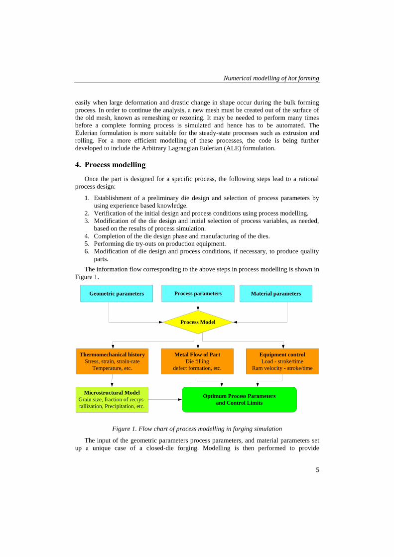
The information flow corresponding to the above steps in process modelling is shown in
Figure 1.
Geometric parameters Process parameters Material parameters
Process Model
Metal Flow of Part
Die filling
defect formation, etc.
Thermomechanical history
Stress, strain, strain-rate
Temperature, etc.
Equipment control
Load - stroke/time
Ram velocity - stroke/time
Microstructural Model
Grain size, fraction of recrys-
tallization, Precipitation, etc.
Optimum Process Parameters
and Control Limits
Figure 1. Flow chart of process modelling in forging simulation
The input of the geometric parameters process parameters, and material parameters set
up a unique case of a closed-die forging. Modelling is then performed to provide
Miklós Tisza, Zsolt Lukács, Gaszton Gál
6
information on the metal flow and thermo-mechanical history of the forging, the
distribution of the state variables at any stage of the forging, and the equipment response
during forging. The histories of the state variables, such as strain, strain rate, temperature,
etc., are then input to the microstructure model for microstructural feature prediction. All of
the information generated used for judging the forging operation. The non-satisfaction in
any of these areas will require a new model with a set of modified process parameters until
the satisfied results are obtained. Then, the optimum process is selected for shop practice.
4.1. Process modelling parameters
The most important input parameters for forging process modelling are the geometric,
the materials and process parameters. In the following, the types and importance of these
input parameters are shortly discussed.
Geometric parameters: The starting workpiece geometry and the die geometry need to
be defined in a closed-die forging modelling. Depending on its complexity, a forging
process can be simulated either as a two-dimensional, axisymmetric or plane-strain, or a
three-dimensional problem. If the process involves multiple stations, the die geometry of
each station needs to be provided.
Material properties: In order to accurately predict the material flow and forming loads,
it is necessary to use reliable input data. The stress-strain relation or flow curve is generally
obtained from a compression test. In most simulations, the tools are considered rigid; thus,
die deformation and stresses are neglected. However, in precision forging operations, the
relatively small elastic deformations of the dies may influence the thermal and mechanical
loading conditions and the contact stress distribution at the die/workpiece interface. Thus,
die stress analysis is a crucial part of process simulation to verify the die design and the
forging process parameters.
Interface conditions: The friction and heat-transfer conditions at the interface between
the die and the billet have a significant effect on the metal flow and the loads required to
produce the part. In forging simulations, due to the high contact stresses at the interface
between the workpiece and the die, the constant shear friction factor gives better results
than the Coulomb friction coefficient. The most common way to determine the constant
shear friction factor in forging is the well-known ring compression test.
Process parameters: The typical process parameters to be considered in a closed-die
forging include: the environment, the workpiece and the die temperatures, the coefficients
of heat transfer between dies and the billet and the atmosphere, the time used to transfer the
workpiece from the furnace to the dies, the time needed to have the workpiece resting on
the bottom die, the workpiece and die interface heat-transfer coefficient during free resting,
the workpiece and die interface heat-transfer coefficient during deformation, the workpiece
and die interface friction, etc. The die velocity is also a very important parameter to be
defined in the modelling of a closed-die forging.
5. Industrial application examples
Process modelling of closed-die forging using finite-element modelling has been
applied in forging industry for a couple of decades. The goal of using computer modelling
in closed-die forging is the rapid development of right-the-first-time processes and to
enhance the performance of components through better process understanding and control.
Numerical modelling of hot forming
7
In its earlier application, process modelling helped die design engineers to preview the
metal flow and possible defect formation in a forging. After the forging simulation is done,
the contours of state variables, such as effective strain, effective strain rate, and temperature
at any instant of time during a forging, can be generated. The thermo-mechanical histories
of selected individual locations within a forging can also be tracked. These functions of
process modelling provided an insight into the forging process that was not available in the
old days. Integrated with the process modelling, microstructure modelling is a new area that
has a bright future [9], [10]. Microstructure modelling allows the optimum metallurgical
features of the forging to be previewed on the computer. Metallurgical aspects of forging,
such as grain size and precipitation can be predicted with reasonable accuracy. Some
proven practical applications will be shortly described in the following parts. One of the
main industrial application fields of forging simulation is the design of forging sequences in
cold, warm, and hot forging, including the determination of preform shapes and dimensions
with the prediction of material flow, the forming forces, die stresses, etc.
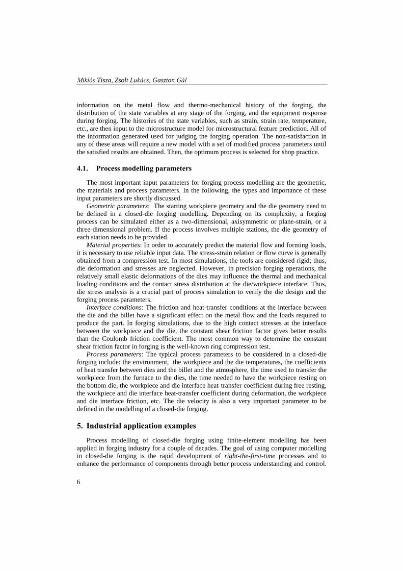
In Figure 2, the final shape and dimensions of an annular gear to be produced by hot
forging can be seen. Due to its complicated shape and strongly changing cross-sections, it is
an excellent example for multi-stage hot forging simulations. Furthermore, due to its de-
signation, it should be also heat-treated, which provides a further possibility to illustrate the
integrated simulation of multi-stage hot forging and heat-treatment processes.
The dimensions of the starting billet are calculated from the final shape and dimensions
of the forged component using the volume constancy rule. The billet is made of plain
carbon steel (C = 0.45 %) from a cylindrical bar with the dimensions: Ø 75 x 120 mm.
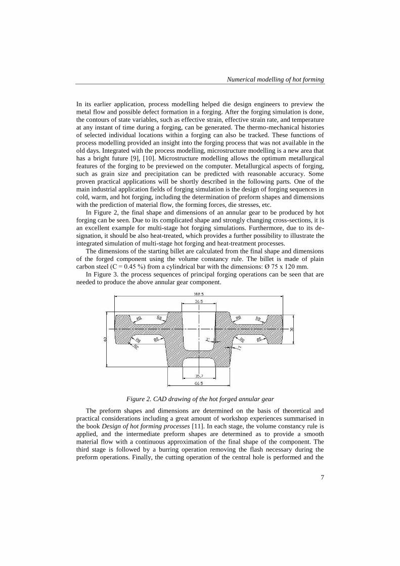
In Figure 3. the process sequences of principal forging operations can be seen that are
needed to produce the above annular gear component.
Figure 2. CAD drawing of the hot forged annular gear
The preform shapes and dimensions are determined on the basis of theoretical and
practical considerations including a great amount of workshop experiences summarised in
the book Design of hot forming processes [11]. In each stage, the volume constancy rule is
applied, and the intermediate preform shapes are determined as to provide a smooth
material flow with a continuous approximation of the final shape of the component. The
third stage is followed by a burring operation removing the flash necessary during the
preform operations. Finally, the cutting operation of the central hole is performed and the
Miklós Tisza, Zsolt Lukács, Gaszton Gál
8
gearing is done by machining operation. The heat-treatment of the component is done by
hardening with subsequent tempering to get the prescribed hardness and other mechanical
properties. The forming of the part is done on a National type hot forming press with a
nominal capacity of 4000 tons and the stroke length of 250 mm.
Figure 3. Process sequence of multi-stage hot forming of annular gear
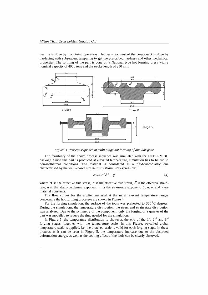
The feasibility of the above process sequence was simulated with the DEFORM 3D
package. Since this part is produced at elevated temperature, simulation has to be run in
non-isothermal conditions. The material is considered as a rigid-viscoplastic one
characterised by the well-known stress-strain-strain rate expression:
n mC y (4)
where is the effective true stress, is the effective true strain, is the effective strain-
rate, n is the strain-hardening exponent, m is the strain-rate exponent, C, n, m and y are
material constants.
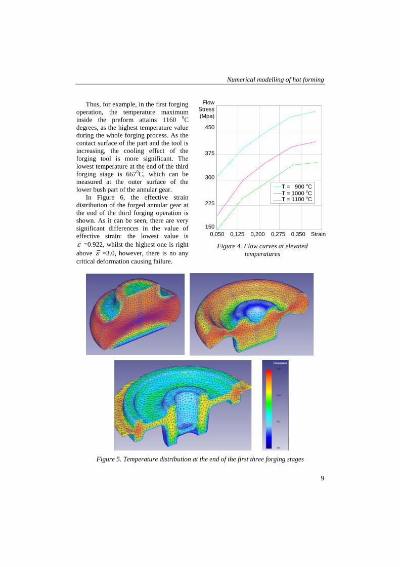
The flow curves for the applied material at the most relevant temperature ranges
concerning the hot forming processes are shown in Figure 4.
For the forging simulation, the surface of the tools was preheated to 350 0C degrees.
During the simulations, the temperature distribution, the stress and strain state distribution
was analysed. Due to the symmetry of the component, only the forging of a quarter of the
part was modelled to reduce the time needed for the simulation.
In Figure 5, the temperature distribution is shown at the end of the 1st, 2
nd and 3
rd
forging stages, together with the temperature scale. In this Figure, so-called global
temperature scale is applied, i.e. the attached scale is valid for each forging stage. In these
pictures as it can be seen in Figure 5, the temperature increase due to the absorbed
deformation energy, as well as the cooling effect of the tools can be clearly observed.
Numerical modelling of hot forming
9
Thus, for example, in the first forging
operation, the temperature maximum
inside the preform attains 1160 0C
degrees, as the highest temperature value
during the whole forging process. As the
contact surface of the part and the tool is
increasing, the cooling effect of the
forging tool is more significant. The
lowest temperature at the end of the third
forging stage is 6670C, which can be
measured at the outer surface of the
lower bush part of the annular gear.
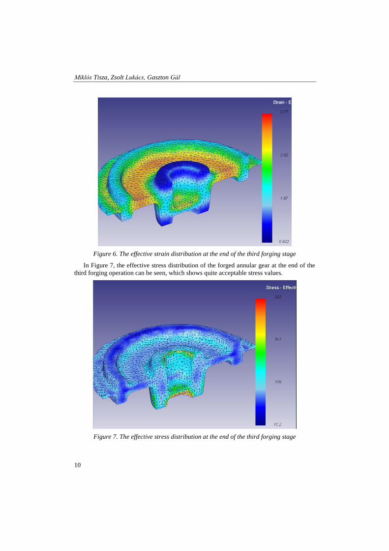
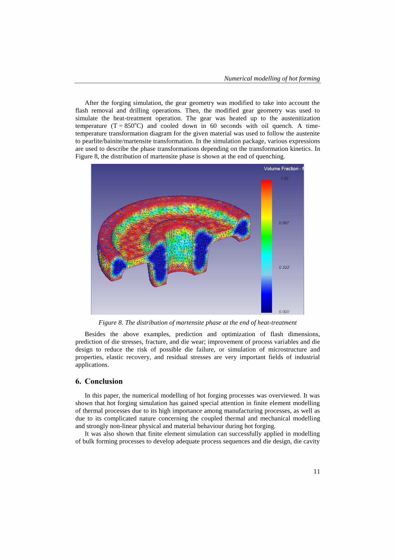
In Figure 6, the effective strain
distribution of the forged annular gear at
the end of the third forging operation is
shown. As it can be seen, there are very
significant differences in the value of
effective strain: the lowest value is
=0.922, whilst the highest one is right
above =3.0, however, there is no any
critical deformation causing failure.
Figure 5. Temperature distribution at the end of the first three forging stages
150
225
300
375
450
Flow
Stress
(Mpa)
T = 900 oC
T = 1000 oC
T = 1100 oC
0,050 0,125 0,200 0,275 0,350 Strain
Figure 4. Flow curves at elevated
temperatures
Miklós Tisza, Zsolt Lukács, Gaszton Gál
10
Figure 6. The effective strain distribution at the end of the third forging stage
In Figure 7, the effective stress distribution of the forged annular gear at the end of the
third forging operation can be seen, which shows quite acceptable stress values.
Figure 7. The effective stress distribution at the end of the third forging stage
Numerical modelling of hot forming
11
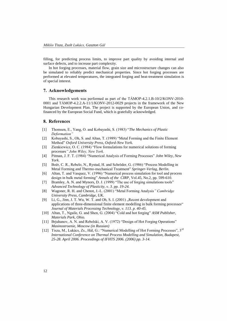
After the forging simulation, the gear geometry was modified to take into account the
flash removal and drilling operations. Then, the modified gear geometry was used to
simulate the heat-treatment operation. The gear was heated up to the austenitization
temperature (T = 850oC) and cooled down in 60 seconds with oil quench. A time-
temperature transformation diagram for the given material was used to follow the austenite
to pearlite/bainite/martensite transformation. In the simulation package, various expressions
are used to describe the phase transformations depending on the transformation kinetics. In
Figure 8, the distribution of martensite phase is shown at the end of quenching.
Figure 8. The distribution of martensite phase at the end of heat-treatment
Besides the above examples, prediction and optimization of flash dimensions,
prediction of die stresses, fracture, and die wear; improvement of process variables and die
design to reduce the risk of possible die failure, or simulation of microstructure and
properties, elastic recovery, and residual stresses are very important fields of industrial
applications.
6. Conclusion
In this paper, the numerical modelling of hot forging processes was overviewed. It was
shown that hot forging simulation has gained special attention in finite element modelling
of thermal processes due to its high importance among manufacturing processes, as well as
due to its complicated nature concerning the coupled thermal and mechanical modelling
and strongly non-linear physical and material behaviour during hot forging.
It was also shown that finite element simulation can successfully applied in modelling
of bulk forming processes to develop adequate process sequences and die design, die cavity
Miklós Tisza, Zsolt Lukács, Gaszton Gál
12
filling, for predicting process limits, to improve part quality by avoiding internal and
surface defects, and to increase part complexity.
In hot forging processes, material flow, grain size and microstructure changes can also
be simulated to reliably predict mechanical properties. Since hot forging processes are
performed at elevated temperatures, the integrated forging and heat-treatment simulation is
of special interest.
7. Acknowledgements
This research work was performed as part of the TÁMOP-4.2.1.B-10/2/KONV-2010-
0001 and TÁMOP-4.2.2.A-11/1/KONV-2012-0029 projects in the framework of the New
Hungarian Development Plan. The project is supported by the European Union, and co-
financed by the European Social Fund, which is gratefully acknowledged.
8. References
[1] Thomsen, E., Yang, O. and Kobayashi, S. (1983) “The Mechanics of Plastic
Deformation”
[2] Kobayashi, S., Oh, S. and Altan, T. (1989) “Metal Forming and the Finite Element
Method” Oxford University Press, Oxford-New York.
[3] Zienkiewicz, O. C. (1984) “Flow formulations for numerical solutions of forming
processes” John Wiley, New York.
[4] Pitman, J. F. T. (1984) “Numerical Analysis of Forming Processes” John Wiley, New
York.
[5] Boër, C. R., Rebelo, N., Rystad, H. and Schröder, G. (1986) “Process Modelling in
Metal Forming and Thermo-mechanical Treatment” Springer-Verlag, Berlin.
[6] Altan, T. and Vasquez, V. (1996) “Numerical process simulation for tool and process
design in bulk metal forming” Annals of the CIRP, Vol.45, No.2, pp. 599-610.
[7] Bramley, A. N. and Mynors, D. J. (1999) “The use of forging simulations tools”
Advanced Technology of Plasticity, v. 3. pp. 19-24.
[8] Wagoner, R. H. and Chenot, J.-L. (2001) “Metal Forming Analysis” Cambridge
University Press, Cambridge, UK.
[9] Li, G., Jinn, J. T. Wu, W. T. and Oh, S. I. (2001) „Recent development and
applications of three-dimensional finite element modelling in bulk forming processes“
Journal of Materials Processing Technology, v. 113. p. 40-45.
[10] Altan, T., Ngaile, G. and Shen, G. (2004) “Cold and hot forging” ASM Publisher,
Materials Park, Ohio.
[11] Brjuhanov, A. N. and Rebelski, A. V. (1972) “Design of Hot Forging Operations”
Masinostroenie, Moscow (in Russian)
[12] Tisza, M., Lukács, Zs., Hál, G.: “Numerical Modelling of Hot Forming Processes”, 3rd
International Conference on Thermal Process Modelling and Simulation, Budapest,
25-28. April 2006. Proceedings of IFHTS 2006. (2006) pp. 3-14.