Embed Size (px)
Citation preview
FACTA UNIVERSITATIS
Series: Architecture and Civil Engineering Vol. 16, No 1, 2018, pp. 135-147
https://doi.org/10.2298/FUACE170830011M
NUMERICAL MODELING OF ULTRASONIC WAVE
PROPAGATION – BY USING OF EXPLICIT FEM IN ABAQUS
UDC 624:517.957]:004.42
Nemanja Marković1, Dragoslav Stojić
1, Radovan Cvetković
1,
Vladimir Radojičić2, Stefan Conić
1
1Department for Materials and Structures, Faculty of Civil Engineering and Architecture,
University of Niš, Serbia 2Faculty of Technical Sciences Priština, Serbia
Abstract. Monitoring of structures implies integration of sensors and actuators, smart
materials, data transfer as well as computer analyses and simulations with the purpose
of damage detection, localization, assessment and prediction of the state of damage at
the certain moment and in time. This paper presents the application of the explicit
finite element method for modeling of the wave propagation. The examples of concrete
plates and thin steel plates in which the propagation of the Lamb waves occur were
analyzed. Explicit finite element method was shown to be very efficient even for the
waves in ultrasound range. Efficiency, ease of the use and reliability of the wave
propagation modeling by the explicit finite element method can contribute to the
development of a new and the improvement of the existing methods for the monitoring
of structures.The main purpose of this paper is to demonstrate a waveform propagation
model using an explicit FEM in ABAQUS software.
Key words: explicit finite element method, structural health monitoring, wave
propagation, piezoelectric sensors, damage detection
1. INTRODUCTION
Computer-aided engineering (CAE) is the broad usage of computer software to aid in
engineering analysis tasks, for mechanical, civil-engineering, air-industry etc. It includes
Finite Element Analysis (FEA), Computational Fluid Dynamics (CFD), Multi-body
dynamics (MBD) and optimization. As Moor’s rule predicted, the computing power
increases tenfold every five years. The CAE engineers have witnessed and enjoyed the
great advances in computer architectures and software functionalities. With growing
Received August 30, 2017 / Accepted October 27, 2017 Corresponding author: Nemanja Marković
Faculty of Civil Engineering and Architecture, University of Niš, 18000 Niš, Aleksandra Medvedeva 14, Serbia
E-mail: [email protected]
136 N. MARKOVIĆ, D. STOJIĆ, R. CVETKOVIĆ, V. RADOJIĈIĆ, S. CONIĆ
computing power, expectations for more accurate predictive analysis have also risen.
Simulation as an important design tool has been built into the manufacturing process. This
represents a tough challenge to engineers as they try to assess the reliability of the results
predicted by the computer simulation, even before the prototype test is conducted. Being
overly reliant on simulation results can sometimes lead to wrong and costly decisions. In
recent years, the concept of verification and validation has been proposed. Verification
and validation is critical for certain types of simulation, whose errors could lead to major
disasters. It is essential to determine how to systematically verify the numerical solution.
It is very difficult to write about when exactly the finite element method (FEM) was
created. The first forms of this method are used for the purpose of civil engineering and
airline industries and it can be said with some reserve that Hrennikoff A. and R. Courant
are the initiators of the FEM. Today, computer simulations which are for the most part
carried out by finite element method, are widespread in scientific research and practical
application. The explicit finite element method has been successfully applied to various
simulations such as wave propagation, nonlinear transient dynamics with small and large
deformations. It is now widely adopted in the manufacturing process as well as in the
research activity. As reported in journals and conferences, many problems have been
solved by using explicit finite element method.
Monitoring of structures using piezoelectric (PZT) patches represents one of the modern
methods of structural health monitoring, which are still in development. Application of PZT
sensors/actuators has been excessively experimentally investigated under the static, dynamic,
and cyclic loading on the structural elements and whole structures such as: beam elements
[1÷3], columns [4÷6], reinforced concrete walls [7], frames [8], piles [9] and bridge
structures [10]. PZT sensors have proven to be multifunctional devices which could be
applied for various purposes, such as monitoring of vehicle induced impact forces on bridges
[11], monitoring of the bond between reinforcement and casted concrete [12], detection of
the damage of reinforcement inside a RC element [13], monitoring of the water content
variation in concrete [14], vibration control of civil engineering structures [15],
determination of early strength of concrete in-situ [16] as well as determination of
compressive stresses due to the seismic actions on RC structures [17].
PZT patches are being used very successfully for monitoring and detection of the
damage of steel and aluminum structures in aircraft industry, civil engineering, mechanical
engineering etc. The use of Lamb waves induced by PZT patches bonded on the structure
surface is of great importance in these types of structures for damage detection and
localization and determination of damage size. For the purpose of damage detection, Pitch-
catch [18], Pulse-echo [19] and Time-reversal [20] methods were experimentally and
numerically analyzed.
Modeling of wave propagation in reinforced-concrete plate elements, using finite
element method and commercial software package ANSYS was applied in [21]. Besides
the use of commercial software package ANSYS, very successful modeling of wave
propagation was performed in software ABAQUS [22] as well as in LS-DYNA [23]. FEM
was successfully applied in modeling of three-dimensional propagation of PZT patch
induced Lamb wave through reinforced composites [24] and homogenous plates [25].
FEM modeling of directed Lamb waves, induced by piezoelectric patches bonded on the
steel plate, was utilized in [26]. There are many published papers showing the application
of FEM modeling of wave propagation.
Numerical Modeling of Ultrasonic Wave Propagation – by Using of Explicit FEM in ABAQUS 137
However, the use of propagation of waves induced by PZT actuators was analyzed
also by the use of other methods. Spectral-element method was used for modeling of wave
propagation in plate elements [27] as well as the local interaction simulation approach [28].
The aim of this paper is to review the efficiency of explicit FEM for the purpose of
modeling wave propagation. This method can be used for general modeling of wave
propagation, but in this paper, the wave propagation induced by PZT smart aggregate
(SA) actuators embedded in reinforced concrete plate elements with a hole was analyzed.
2. THEORY OF LAMB WAVES
Lamb waves propagate in solid plates. They are elastic waves whose particle motion
lies in plane direction. Lamb waves may propagate in free plates with parallel sides.
Basic concepts of the Lamb wave propagation presented in this paper were used from
reference [29]. In thin isotropic and homogeneous plates the waves, regardless of the
mode, can generally be described in a form of Cartesian tensor notation as [30]:
, ,( )i jj j ji i iG u G u f u , 1,2,3i j (1)
with the following designations: ui is displacement, fi is body force, ρ is density, G is
shear modulus, and λ is Lame constant.
Using Helmholtz decomposition equation (1) can be decomposed into two uncoupled
parts under the plane strain condition:
2 2 2
2 2 2 21 3
1
Lx x c t
(2)
2 2 2
2 2 2 21 3
1
Sx x c t
(3)
Where:
1 3 2 3 1[ sin( ) cos( )] exp[ ( )]A px A px i kx t (4)
1 3 2 3 1[ sin( ) cos( )] exp[ ( )]B qx B qx i kx t (5)
2
2 2
2L
p kc
,
22 2
2T
q kc
,
2
wave
k
(6)
with the following designations: A1, A2, B1 and B2 are four constants determined by the
boundary conditions, k is wave number, ω is circular frequency and λwave is wavelength of
the wave. Longitudinal velocity cL and transverse (shear) velocity cS are defined by:
(1 ) 2 (1 )
(1 )(1 2 ) (1 2 )L
E Gc
(7)
2 (1 )
S
E Gc
(8)
138 N. MARKOVIĆ, D. STOJIĆ, R. CVETKOVIĆ, V. RADOJIĈIĆ, S. CONIĆ
If we assume plane strain conditions, the displacement in the wave propagation direction
(x1) and normal direction (x3) can be described as:
11 3
ux x
, 2 0u , 33 1
ux x
(9)
However, the conditions which correspond to the propagation of Lamb waves:
0( , ) ( , )u x t u x t , i ji jt n , 31 33 0 at 3 / 2x d h (10)
where d is plate thickness and h is half plate thickness. By applying the boundary
conditions defined by equation (10) to equation (9) we can obtain the general description
of Lamb waves in an isotropic and homogeneous plate:
2
2 2 2 2 2
tan( ) 4
tan( ) ( 2 )( )
qh k qpG
ph k p Gp k q
(11)
Applying equation (6) and equations (7) and (8) into the equation (11), and
considering trigonometric features of the above equation, equation (11) can be split into
two parts with unique symmetric and anti-symmetric properties, respectively, implying
that Lamb waves in a plate consist of symmetric and anti-symmetric modes [30]:
2
2 2 2
tan( ) 4
tan( ) ( )
qh k qp
ph k q
- Symmetric modes (12)
2 2 2
2
tan( ) ( )
tan( ) 4
qh k q
ph k qp
- Anti-symmetric modes (13)
Equations (12) and (13) are known as the Rayleigh-Lamb equations.
3. EXPLICIT FINITE ELEMENT METHOD
Since the process of explicit finite element method is explained in many publications
so far, here we will give only a brief overview of the basic equations and rules. Starting
with Newton’s second law written in matrix form:
F M A (14)
with the following designations: F is body force, M is mass matrix, and A is acceleration.
Whereby members of the expression can be defined by the following expressions:
,( )
S
mi ij M j i M i M SF d f d g d
(15)
( )MN M NM d
(16)
( )N Ni iA u t (17)
Numerical Modeling of Ultrasonic Wave Propagation – by Using of Explicit FEM in ABAQUS 139
Where: Fi
m is body force; ij is stress; M, N are based functions; gi represents the
components of the tractions on part of the boundary S; MMN is mass matrix; is mass
density; fi represents the components of the body force; üiN, u is second derivation of
displacement and displacement; Ai
N is acceleration; t is time; is space domain; S is
boundary domain.
More detailed explanation of the elements of equations can be found in [31]. System
defined by equation (14-17) is a system of second-order ordinary differential equations in
time, whether linear or nonlinear. For solving this system explicit scheme uses central
difference method to approximate the acceleration, velocity and displacement. Assume
that the time domain [0,T] is uniformly divided into N equal subintervals [tn, tn+1], with
0=t0< t1<… tN=T, tn+1tn=∆t=T/N. The displacement, velocity and acceleration as time
derivatives are approximated by the finite difference method, expressed in the vector form
as:
2
1/ 2 1 1/ 2
21/ 2 1/ 2 1 1
1/ 2 1/ 2
( ) /
( ) / ( 2 ) /
( ) /
h h h ht n n n n
h h h h h hn t n t n n n nt
h h hn n n
u u u t u
u u u t u u u t
u u u t
(18)
21/ 2 1/ 2
1 1/ 2
h h ht n t n nt
h h hn n t n
u u u t
u u u t
(19)
where u is displacement, u is velocity and ü is acceleration. ∆t (subinterval) is equal to
tn+1tn or T/N.
Approximated the acceleration by central difference method defined in (18) and (19),
the finite element equation (14) is reduced:
21h
n ntu M F (20)
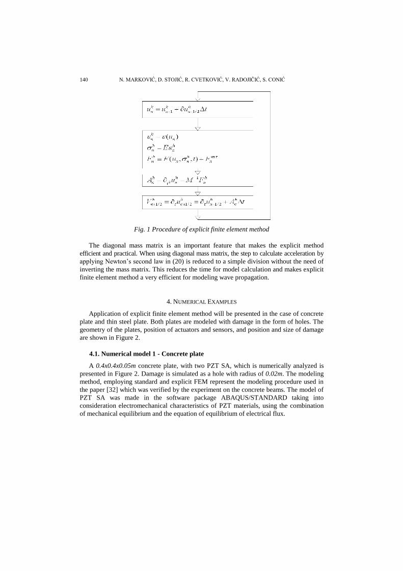
The explicit finite element procedure can be presented as an algorithm in Figure 1.
The implementation of equation (20) is conditionally stable and the time step ∆t has to
be smaller than the critical time step ∆tcrit which in an undamped system depends on the
higher frequency in the smallest element:
max
2critt t
f (21)
For wave propagation modeling, as small deformations of elements is assumed, an
approximation often used is that the critical time step is the transit time of a dilatational
wave through the smallest element in the model:
critL
Lt t
c
(22)
where ∆L is the smallest element size, ∆t is time step and ∆tcrit is critical time step.
In this paper, the criterion for defining the time step is defined by the basis of equation
(22). The size of the final element is adapted to satisfy the usual condition that a
wavelength divided by a final element is greater than ten.
140 N. MARKOVIĆ, D. STOJIĆ, R. CVETKOVIĆ, V. RADOJIĈIĆ, S. CONIĆ
Fig. 1 Procedure of explicit finite element method
The diagonal mass matrix is an important feature that makes the explicit method
efficient and practical. When using diagonal mass matrix, the step to calculate acceleration by
applying Newton’s second law in (20) is reduced to a simple division without the need of
inverting the mass matrix. This reduces the time for model calculation and makes explicit
finite element method a very efficient for modeling wave propagation.
4. NUMERICAL EXAMPLES
Application of explicit finite element method will be presented in the case of concrete
plate and thin steel plate. Both plates are modeled with damage in the form of holes. The
geometry of the plates, position of actuators and sensors, and position and size of damage
are shown in Figure 2.
4.1. Numerical model 1 - Concrete plate
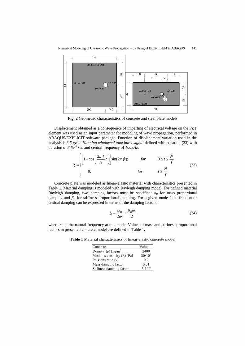
A 0.4x0.4x0.05m concrete plate, with two PZT SA, which is numerically analyzed is
presented in Figure 2. Damage is simulated as a hole with radius of 0.02m. The modeling
method, employing standard and explicit FEM represent the modeling procedure used in
the paper [32] which was verified by the experiment on the concrete beams. The model of
PZT SA was made in the software package ABAQUS/STANDARD taking into
consideration electromechanical characteristics of PZT materials, using the combination
of mechanical equilibrium and the equation of equilibrium of electrical flux.
Numerical Modeling of Ultrasonic Wave Propagation – by Using of Explicit FEM in ABAQUS 141
Fig. 2 Geometric characteristics of concrete and steel plate models
Displacement obtained as a consequence of imparting of electrical voltage on the PZT
element was used as an input parameter for modeling of wave propagation, performed in
ABAQUS/EXPLICIT software package. Function of displacement variation used in the
analysis is 3.5 cycle Hanning windowed tone burst signal defined with equation (23) with
duration of 3.5e-5
sec and central frequency of 100kHz.
21 cos sin(2 ); 0
0;
t
f Nt ft for t
N fP
Nfor t
f
(23)
Concrete plate was modeled as linear-elastic material with characteristics presented in
Table 1. Material damping is modeled with Rayleigh damping model. For defined material
Rayleigh damping, two damping factors must be specified: αR for mass proportional
damping and βR for stiffness proportional damping. For a given mode I the fraction of
critical damping can be expressed in terms of the damping factors:
2 2
R iRi
i
(24)
where ωi is the natural frequency at this mode. Values of mass and stiffness proportional
factors in presented concrete model are defined in Table 1.
Table 1 Material characteristics of linear-elastic concrete model
Concrete Value
Density (ρ) [kg/m3] 2400
Modulus elasticity (E) [Pa] 30·109
Poissons ratio (ν) 0.2
Mass damping factor 0.01
Stiffness damping factor 5·10-8
142 N. MARKOVIĆ, D. STOJIĆ, R. CVETKOVIĆ, V. RADOJIĈIĆ, S. CONIĆ
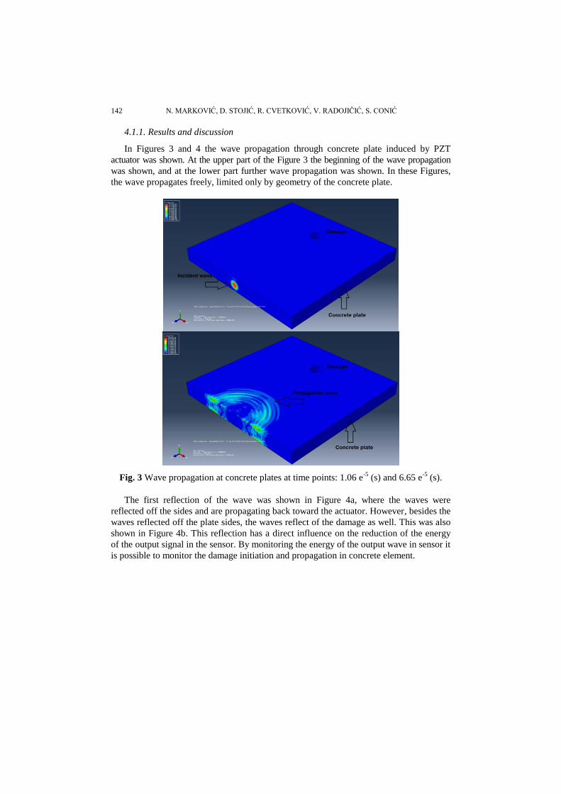
4.1.1. Results and discussion
In Figures 3 and 4 the wave propagation through concrete plate induced by PZT
actuator was shown. At the upper part of the Figure 3 the beginning of the wave propagation
was shown, and at the lower part further wave propagation was shown. In these Figures,
the wave propagates freely, limited only by geometry of the concrete plate.
Fig. 3 Wave propagation at concrete plates at time points: 1.06 e-5
(s) and 6.65 e-5
(s).
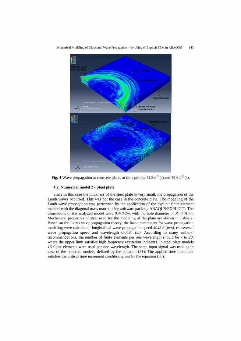
The first reflection of the wave was shown in Figure 4a, where the waves were
reflected off the sides and are propagating back toward the actuator. However, besides the
waves reflected off the plate sides, the waves reflect of the damage as well. This was also
shown in Figure 4b. This reflection has a direct influence on the reduction of the energy
of the output signal in the sensor. By monitoring the energy of the output wave in sensor it
is possible to monitor the damage initiation and propagation in concrete element.
Numerical Modeling of Ultrasonic Wave Propagation – by Using of Explicit FEM in ABAQUS 143
Fig. 4 Wave propagation at concrete plates at time points: 11.2 e-5
(s) and 19.6 e
-5 (s).
4.2. Numerical model 2 - Steel plate
Since in this case the thickness of the steel plate is very small, the propagation of the
Lamb waves occurred. This was not the case in the concrete plate. The modeling of the
Lamb wave propagation was performed by the application of the explicit finite element
method with the diagonal mass matrix using software package ABAQUS/EXPLICIT. The
dimensions of the analyzed model were 0.4x0.2m, with the hole diameter of R=0.015m.
Mechanical properties of steel used for the modeling of the plate are shown in Table 2.
Based on the Lamb wave propagation theory, the basic parameters for wave propagation
modeling were calculated: longitudinal wave propagation speed 4943.3 (m/s), transversal
wave propagation speed and wavelength 0.0494 (m). According to many authors’
recommendations, the number of finite elements per one wavelength should be 7 to 20,
where the upper limit satisfies high frequency excitation incidents. In steel plate models
16 finite elements were used per one wavelength. The same input signal was used as in
case of the concrete models, defined by the equation (31). The applied time increment
satisfies the critical time increment condition given by the equation (30).
144 N. MARKOVIĆ, D. STOJIĆ, R. CVETKOVIĆ, V. RADOJIĈIĆ, S. CONIĆ
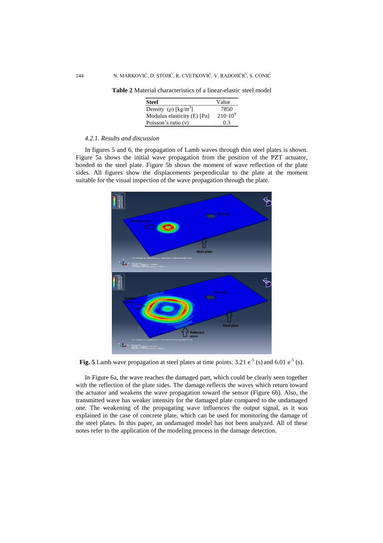
Table 2 Material characteristics of a linear-elastic steel model
Steel Value
Density (ρ) [kg/m3] 7850
Modulus elasticity (E) [Pa] 210·109
Poisson’s ratio (ν) 0.3
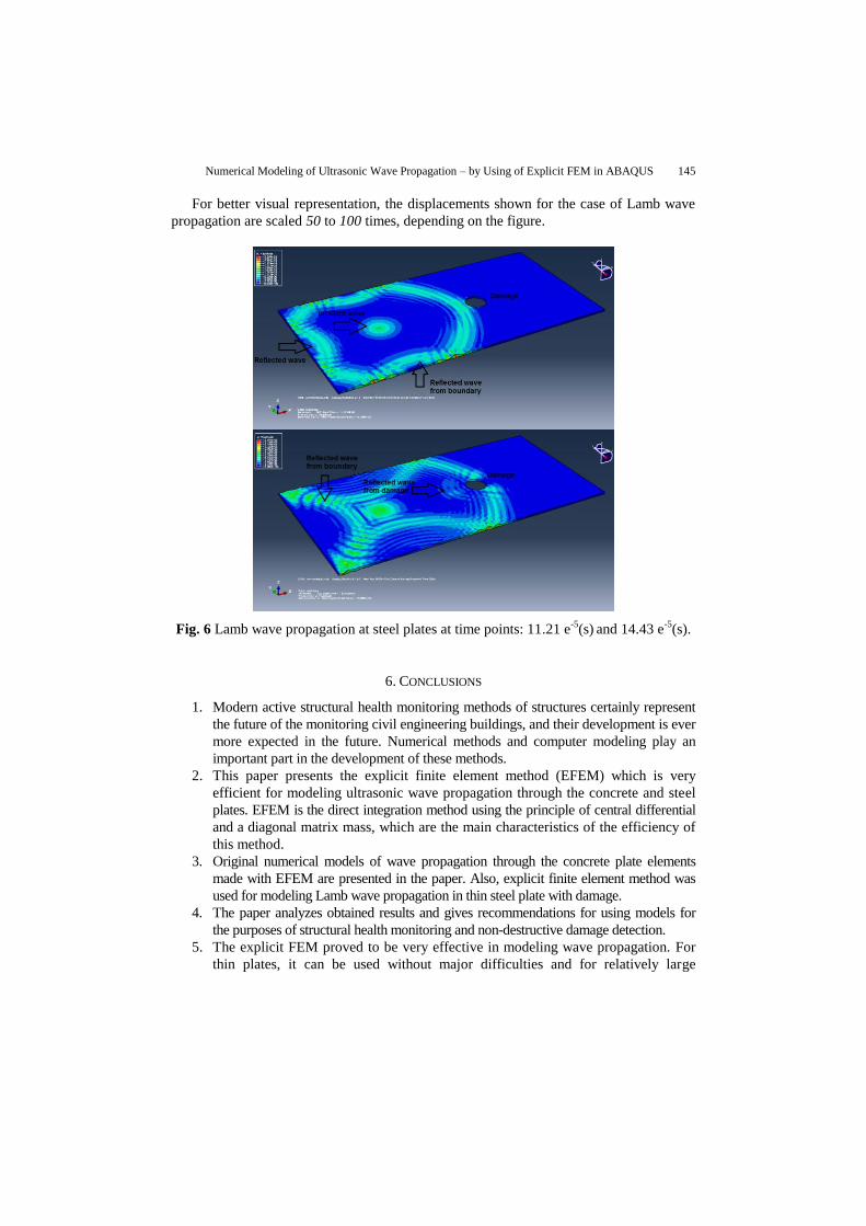
4.2.1. Results and discussion
In figures 5 and 6, the propagation of Lamb waves through thin steel plates is shown.
Figure 5a shows the initial wave propagation from the position of the PZT actuator,
bonded to the steel plate. Figure 5b shows the moment of wave reflection of the plate
sides. All figures show the displacements perpendicular to the plate at the moment
suitable for the visual inspection of the wave propagation through the plate.
Fig. 5 Lamb wave propagation at steel plates at time points: 3.21 e-5
(s) and 6.01 e
-5 (s).
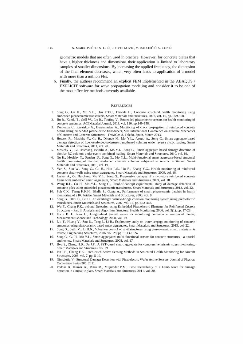
In Figure 6a, the wave reaches the damaged part, which could be clearly seen together
with the reflection of the plate sides. The damage reflects the waves which return toward
the actuator and weakens the wave propagation toward the sensor (Figure 6b). Also, the
transmitted wave has weaker intensity for the damaged plate compared to the undamaged
one. The weakening of the propagating wave influences the output signal, as it was
explained in the case of concrete plate, which can be used for monitoring the damage of
the steel plates. In this paper, an undamaged model has not been analyzed. All of these
notes refer to the application of the modeling process in the damage detection.
Numerical Modeling of Ultrasonic Wave Propagation – by Using of Explicit FEM in ABAQUS 145
For better visual representation, the displacements shown for the case of Lamb wave
propagation are scaled 50 to 100 times, depending on the figure.
Fig. 6 Lamb wave propagation at steel plates at time points: 11.21 e-5
(s) and 14.43 e
-5(s).
6. CONCLUSIONS
1. Modern active structural health monitoring methods of structures certainly represent
the future of the monitoring civil engineering buildings, and their development is ever
more expected in the future. Numerical methods and computer modeling play an
important part in the development of these methods.
2. This paper presents the explicit finite element method (EFEM) which is very
efficient for modeling ultrasonic wave propagation through the concrete and steel
plates. EFEM is the direct integration method using the principle of central differential
and a diagonal matrix mass, which are the main characteristics of the efficiency of
this method.
3. Original numerical models of wave propagation through the concrete plate elements
made with EFEM are presented in the paper. Also, explicit finite element method was
used for modeling Lamb wave propagation in thin steel plate with damage.
4. The paper analyzes obtained results and gives recommendations for using models for
the purposes of structural health monitoring and non-destructive damage detection.
5. The explicit FEM proved to be very effective in modeling wave propagation. For
thin plates, it can be used without major difficulties and for relatively large
146 N. MARKOVIĆ, D. STOJIĆ, R. CVETKOVIĆ, V. RADOJIĈIĆ, S. CONIĆ
geometric models that are often used in practice. However, for concrete plates that
have a higher thickness and dimensions their application is limited to laboratory
samples of smaller dimensions. By increasing the applied frequency, the dimension
of the final element decreases, which very often leads to application of a model
with more than a million FEs.
6. Finally, the authors recommend an explicit FEM implemented in the ABAQUS /
EXPLICIT software for wave propagation modeling and consider it to be one of
the most effective methods currently available.
REFERENCES
1. Song G., Gu H., Mo Y.L., Hsu T.T.C., Dhonde H., Concrete structural health monitoring using
embedded piezoceramic transducers, Smart Materials and Structures, 2007, vol. 16, pp. 959-968.
2. Hu B., Kundu T., Grill W., Liu B., Toufing V., Embedded piezoelectric sensors for health monitoring of
concrete structures, ACI Material Journal, 2013, vol. 110, pp.149-158.
3. Dumoulin C., Karaiskos G., Deraemaeker A., Monitoring of crack propagation in reinforced concrete
beams using embedded piezoelectric transducers, VIII International Conference on Fracture Mechanics
of Concrete and Concrete Structures – FraMCos-8, Toledo, Spain, March 2013.
4. Howser R., Moslehy Y., Gu H., Dhonde H., Mo Y.L., Ayoub A., Song G., Smart-aggregate-based
damage detection of fiber-reinforced-polymer-strengthened columns under reverse cyclic loading, Smart
Materials and Structures, 2011, vol. 20.
5. Moslehy Y., Gu Haichang, Belarbi A., Mo Y.L., Song G., Smart aggregate based damage detection of
circular RC columns under cyclic combined loading, Smart Materials and Structures, 2010, vol. 19.
6. Gu H., Moslehy Y., Sanders D., Song G., Mo Y.L., Multi-functional smart aggregate-based structural
health monitoring of circular reinforced concrete columns subjected to seismic excitation, Smart
Materials and Structures, 2010, vol. 19.
7. Yan S., Sun W., Song G., Gu H., Huo L.S., Liu B., Zhang Y.G., Health monitoring of reinforced
concrete shear walls using smart aggregates, Smart Materials and Structures, 2009, vol. 18.
8. Laskar A., Gu Haichang, Mo Y.L., Song G., Progressive collapse of a two-story reinforced concrete
frame with embedded smart aggregates, Smart Materials and Structures, 2009, vol. 18.
9. Wang R.L., Gu H., Mo Y.L., Song G., Proof-of-concept experimental study of damage detection of
concrete piles using embedded piezoceramic transducers, Smart Materials and Structures, 2013, vol. 22.
10. Soh C.K., Tseng K.K.H., Bhalla S., Gupta A., Performance of smart piezoceramic patches in health
monitoring of a RC bridge, Smart Materials and Structures, 2000, vol. 9.
11. Song G., Olmi C., Gu H., An overheight vehicle-bridge collision monitoring system using piezoelectric
transducers, Smart Materials and Structures, 2007, vol. 16, pp. 462-468.
12. Wu F., Chang F.K., debond Detection using Embedded Piezoelectric Elements for Reinforced Cocrete
Structures – Part II: Analysis and Algorithm, Structural Health Monitoring, 2006, vol. 5(1), pp. 17-28.
13. Ervin B. L., Reis H., Longitudinal guided waves for monitoring corrosion in reinforced mortar,
Measurement Science and Technology, 2008, vol. 19.
14. Liu T., Huang Y., Zou D., Teng J., Li B., Exploratory study on water seepage monitoring of concrete
structures using piezoceramic based smart aggregates, Smart Materials and Structures, 2013, vol. 22.
15. Song G., Sethi V., Li H.N., Vibration control of civil structures using piezoceramic smart materials: A
review, Engineering Structures, 2006, vol. 28, pp. 1513-1524.
16. Song G., Gu H., Mo Y.L., Smart aggregates: multi-functional sensors for concrete structures – a tutorial
and review, Smart Materials and Structures, 2008, vol. 17.
17. Hou S., Zhang H.B., Ou J.P., A PZT-based smart aggregate for compressive seismic stress monitoring,
Smart Materials and Structures, vol. 21.
18. Ihn J.B., Chang F.K., Pitch-catch Active Sensing Methods in Structural Health Monitoring for Aircraft
Structures, 2008, vol. 7, pp. 5-19.
19. Giurgiutiu V., Structural Damage Detection with Piezoelectric Wafer Active Sensors, Journal of Physics:
Conference Series 305, 2011.
20. Poddar B., Kumar A., Mitra M., Mujumdar P.M., Time reversibility of a Lamb wave for damage
detection in a metallic plate, Smart Materials and Structures, 2011, vol. 20.
Numerical Modeling of Ultrasonic Wave Propagation – by Using of Explicit FEM in ABAQUS 147
21. F. Song, G.L. Huang, J. H. Kim, S. Haran, On the study of surface wave propagation in concrete structures
using a piezoelectric actuators/sensor system, Smart Materials and Structures, 2008, vol. 17, 8pp.
22. N. Marković, D. Stojić, T. Nestorović, Modeliranje Lamb talasa kod tankih ĉeliĉnih ploĉa u cilju
detekcije oštećenja, Zbornik radova GraĊevinsko-arhitektonskog fakulteta u Nišu, 2014, vol. 29, pp. 1-14.
23. M. Yang, P. Qiao. Modeling and experimental detection of damage in various materials using the pulse-echo
method and piezoelectric sensors/actuators. Smart Materials and Structures, 2005, vol.14, pp.1083-1100.
24. R. Weber, S. M. H. Hosseini, U. Gabbert. Numerical simulation of the guided Lamb wave propagation
in particle reinforced composites. Composite Structures, 2012, vol. 94, pp. 3064-3071.
25. S. V. Ende, R. Lammering. Modeling and Simulation of Lamb Wave Generation with Piezoelctric
Plates. Mechanics of Advanced Materials and Structures, 2009, vol. 16, pp. 188-197.
26. W. Zhou, H. Li, F. G. Yuan. Guided wave generation, sensing and damage detection using in-plane
shear piezoelectric wafers. Smart Materials and Structures, 2014, vol.23, 10pp.
27. M. Rucka. Modelling of in-plane wave propagation in a plate using spectral element method and Kane-
Midlin theory with application to damage detection. Archives of Applied Mechanics, 2011, vol. 81,
pp.1877-1888.
28. B. C. Lee, W. J. Staszewski. Modelling of Lamb waves for damage detection in metallic structures: Part
I. Wave Propagation. Smart Materials and Structures, 2003, vol. 12, pp. 804-814.
29. Z. Su, L. Ye, Identification of Damage Using Lamb Waves – From Fundamentals to Applications,
Lecture Notes in Applied and Computational Mechanics, vol. 48. Springer, 2009, pp. 15- 58.
30. J. L. Rose, Ultrasonic Waves in Solid Media, Cambridge University press, New York, 1999.
31. Shen R. Wu, Lei Gu, Introduction to the Explicit Finite Element Method for nonlinear transient
dynamics, Wiley, New Jersey, 2012.
32. N. Marković, T. Nestorović, D. Stojić, Numerical Modeling of Damage Detection in Concrete Beams
using Piezoelectric Patches, Mechanics Research Communications, 2015, vol. 64, pp 15-22.
NUMERIČKO MODELIRANJE ULTRAZVUČNOG
PROSTIRANJA TALASA – KORISTEČI EKSPLICTINU MKE
U ABAQUSU
Monitoring konstrukcija podrazumeva integrisanje senzora i aktuatora, pametnih materijala,
prenosa podataka kao i kompjuterskih analiza i simulacija u cilju detekcije, lokalizacije, procene i
predviđanja stanja oštećenja u datom trenutku i kroz vreme. U radu je prikazana primena
eksplicitne metode konačnih elemenata za modeliranje propagacije talasa. Metoda je direktna
integraciona metoda koja koristi dijagonalnu matricu masa. Analizirani su primeri betonskih
ploča i tankih čeličnih ploča kod kojih se javlja prostiranje Lamb talasa. Eksplicitna metoda
konačnih elemenata se pokazala veoma efikasnom čak i za talase u ultrazvučnom opsegu.
Efikasnost, laka upotreba i pouzdanost modela propagacije talasa izvedenih eksplictinom
metodom konačnih elemenata mogu doprineti u razvoju novih ili unapređenju postojećih metoda
monitoringa konstrukcija.
Kljuĉne reĉi: eksplicitna metoda konačnih elemenata, monitoring konstrukcija, propagacija talasa,
piezoelektrični senzori, detekcija oštećenja