Embed Size (px)
Citation preview

1
Numerical Methodology for the Assessment of Relative and Absolute Deterministic Flow Structures in the Analysis of
Impeller‐Tongue Interactions for Centrifugal Fans
Fernández Oro, J.M.(1); Pereiras García, B.; González Pérez, J.; Argüelles Díaz, K.M.; Velarde‐Suárez, S.
Universidad de Oviedo, Área de Mecánica de Fluidos. Campus de Viesques, 33271, Gijón (Asturias), Spain.
ABSTRACT
In this paper a numerical methodology to segregate relative and absolute flow structures, allowing a deep analysis of the impeller‐tongue interaction in centrifugal fans, is presented. The procedure, based on a deterministic decomposition of the internal flow fields, is applied for first time in blade‐to‐blade planes of radial turbomachinery. Previous numerical results, obtained with a viscous 3D unsteady solver, already validated by the authors and available in the literature, are used as a database for the numerical routines. Interpolation and relocating operations of the velocity fields between CFD meshes and post‐processing grids are presented and performed for different flow rates of a squirrel cage fan. This numerical technique is shown as an ideal framework to advance in the physical comprehension of the complexity, three‐dimensionality and unsteadiness of the flow structures in the interaction regions of centrifugal fans. Additionally, the different contributors to the unsteady forces on the blades are also addressed, providing a valuable insight to identify the origin of the interaction phenomena for both diagnosis and redesign criteria of impeller and volute geometries.
The squirrel cage fan studied is a small centrifugal fan with a twin impeller configuration, each with 23 forward curved blades, a nominal flow rate at around 352 m3/h and a specific speed ns = 1.9. This type of squirrel cage fans is often used as blowers for automobile applications or for small industrial equipment. The flow in this kind of fans happens to be quite complex and with unsteady features. Unsteady flow separation at the machine inlet or at the impeller blades and a variety of flow induced vibrations is found for most of the operation conditions. In this context, the deterministic decomposition becomes an essential tool to analyze the main flow structures, like the evaluation of the non‐uniformities induced by the volute tongue over the blade‐to‐blade distributions within the impeller. As a consequence, fluctuation levels in the blade loadings, derived from deterministic non‐uniformities, can be provided in the relative frame of reference. The practical applications of the conclusions do imply a progress in the knowledge of the working parameters for machines that affect in a direct way to the passengers comfort.
Keywords: centrifugal squirrel‐cage fan, unsteady flow, CFD, deterministic decoupling, impeller‐tongue interaction, numerical post‐processing.

2
1.‐ INTRODUCTION
Squirrel‐cage fans are a kind of centrifugal fans with large number of short chord forward‐curved blades. These fans are widely used in applications requiring small size, relatively high flow rate and low cost. In particular, squirrel‐cage fans of small size are frequently used in air conditioning systems of buildings and passenger vehicles [1]. Therefore, the noise generated by these machines becomes a serious problem, as far as human users would be very close to their locations. These fans usually exhibit instability phenomena, which reduce their operating range. A basic feature of their impellers is the deficient flow guiding, as a result of the short radial length of the blades and their strong curvature. This effect is counterbalanced by a greater number of blades. Such an arrangement can cause the flow to stall, even at design conditions. Typically, the poor design of the flow channel in these fans causes a severely distorted primary flow [2], with early flow separation on the suction side at both low and design flow rates. It is also well‐known the inefficiencies of these machines to the sharp axial to radial bend, the large inlet gap between inlet nozzle and impeller shroud and the poor matching between impeller outlet and volute tongue [3].
The designers of squirrel‐cage fans, and in general of any turbomachine, are stirred by the selection of smaller, more efficient and quieter prototypes [4]. Several studies have stressed the growing importance of numerical methods in the description of the complex 3D unsteady flows for these purposes in turbomachinery applications. However, the achievement of such 3D models becomes a difficult task if the balance between flow definition and computer requirements is considered. Moreover, experimental validation of the results is an additional requirement, to be provided at some initial stage of the modelling [5]. Some of the most recent works related to centrifugal fans have combined numerical and experimental procedures and have contributed to a deeper understanding of the particular characteristics of such machines [6,7,8]. In particular, averaged contributions of the unsteady flow features regarding pressure fluctuations, aerodynamic performance, impeller‐tongue interaction or tip region flows [9] have been reported in last years, providing notable contributions on the understanding of three‐dimensionality and complex internal flows of centrifugal fans. Currently, modelling efforts are mainly focused on the evaluation of aerodynamic noise sources and the development of acoustic numerical simulations for noise prediction (both tonal and broadband contributions) [10,11,12].
However, despite the valuable achievements obtained in numerical modelling during the last decade, it is still necessary to provide more physical insight to the flow characteristics of centrifugal fans, especially for new design tools. At this point, the deterministic framework [13], developed as a complete equation system to resolve numerically the blade row interaction in turbomachinery using an additional stress tensor that accounts for the deterministic fluctuations, becomes a key instrument for the analysis of the unsteadiness. In fact, the modelling of deterministic stresses addresses the time‐averaged impact of the interaction between the impeller flow and the stator, diffuser or a simple volute tongue. It can be used for modelling issues [14,15] or to identify the unsteady sources in both numerical or experimental (PIV, HW) databases [16,17]. Reoriented as a post‐processing tool by the authors [18], it has already shown its ability with radial turbomachinery to evaluate the impact of non‐uniformities induced by fixed elements (volute tongue) over the blade‐to‐blade distributions at the impeller exit of a double‐suction centrifugal pump [19]. In the present article, this numerical methodology is extended to analyze blade‐to‐blade planes in this type of centrifugal fans for the first time. Using the numerical model presented and validated in [20], a comprehensive decomposition of the unsteady flow in both relative and absolute frames of reference is carried out in order to provide a deep understanding
3
of the tongue‐impeller interaction, revealing non‐linear components in the phase dependent interaction. Interpolation routines and relocating algorithms, relating circumferential and temporal discretizations, are employed to segregate the different velocity components in both fixed and rotating frames of reference. The procedure highlights the importance of the deterministic unsteadiness, revealing the underlying non‐linear volute‐impeller interaction. In addition, the different contributors to the unsteady forces on the blades are also addressed, providing a valuable insight to identify the main structure responsible for mechanical pulsations on the impeller. Finally, deterministic stresses (in terms of deterministic kinetic energy) are computed to show the location and intensity of the main unsteady sources. The comparison of these terms with the turbulent kinetic energy (in both reference frames) will complete the study, giving the relative importance of both turbulent and deterministic scales into the total unsteady patterns.
2.‐ MACHINE DESCRIPTION
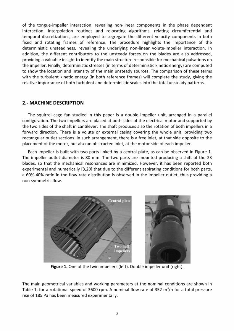
The squirrel cage fan studied in this paper is a double impeller unit, arranged in a parallel configuration. The two impellers are placed at both sides of the electrical motor and supported by the two sides of the shaft in cantilever. The shaft produces also the rotation of both impellers in a forward direction. There is a volute or external casing covering the whole unit, providing two rectangular outlet sections. In such arrangement, there is a free inlet, at that side opposite to the placement of the motor, but also an obstructed inlet, at the motor side of each impeller.
Each impeller is built with two parts linked by a central plate, as can be observed in Figure 1. The impeller outlet diameter is 80 mm. The two parts are mounted producing a shift of the 23 blades, so that the mechanical resonances are minimized. However, it has been reported both experimental and numerically [3,20] that due to the different aspirating conditions for both parts, a 60%‐40% ratio in the flow rate distribution is observed in the impeller outlet, thus providing a non‐symmetric flow.
Figure 1. One of the twin impellers (left). Double impeller unit (right).
The main geometrical variables and working parameters at the nominal conditions are shown in Table 1, for a rotational speed of 3600 rpm. A nominal flow rate of 352 m3/h for a total pressure rise of 185 Pa has been measured experimentally.
4
Table 1. Basic geometrical parameters of the fan
Number of blades per impeller, B [‐] 23+23
Impeller inlet diameter, D1/ D2 [‐] 0.75
Impeller outer diameter, D2 [m] 0.08
Impeller width, b2/D2 [‐] 1.175
Specific speed, nS [‐] 1.9
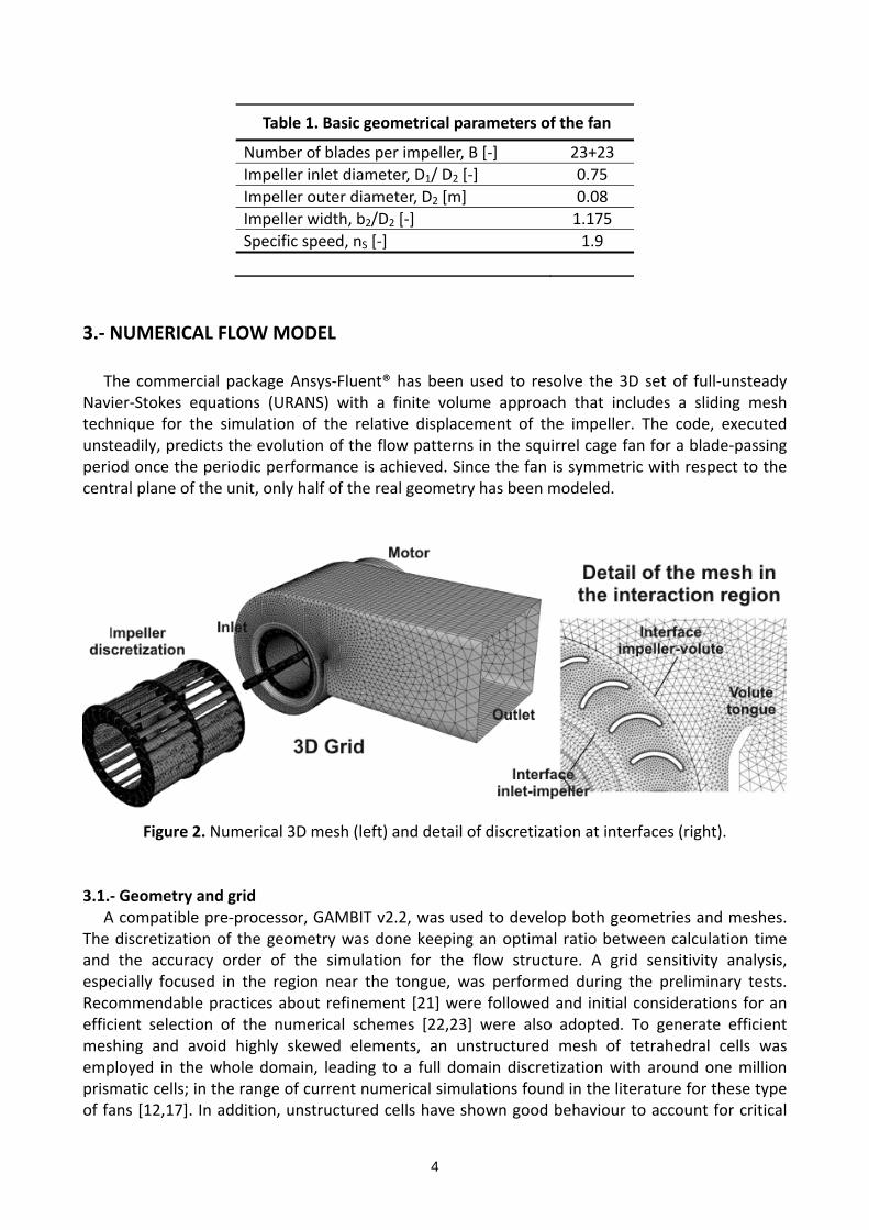
3.‐ NUMERICAL FLOW MODEL The commercial package Ansys‐Fluent® has been used to resolve the 3D set of full‐unsteady Navier‐Stokes equations (URANS) with a finite volume approach that includes a sliding mesh technique for the simulation of the relative displacement of the impeller. The code, executed unsteadily, predicts the evolution of the flow patterns in the squirrel cage fan for a blade‐passing period once the periodic performance is achieved. Since the fan is symmetric with respect to the central plane of the unit, only half of the real geometry has been modeled.
Figure 2. Numerical 3D mesh (left) and detail of discretization at interfaces (right).
3.1.‐ Geometry and grid
A compatible pre‐processor, GAMBIT v2.2, was used to develop both geometries and meshes. The discretization of the geometry was done keeping an optimal ratio between calculation time and the accuracy order of the simulation for the flow structure. A grid sensitivity analysis, especially focused in the region near the tongue, was performed during the preliminary tests. Recommendable practices about refinement [21] were followed and initial considerations for an efficient selection of the numerical schemes [22,23] were also adopted. To generate efficient meshing and avoid highly skewed elements, an unstructured mesh of tetrahedral cells was employed in the whole domain, leading to a full domain discretization with around one million prismatic cells; in the range of current numerical simulations found in the literature for these type of fans [12,17]. In addition, unstructured cells have shown good behaviour to account for critical

5
flow features, such as separation; thus considering the mesh appropriate for the present application. Figure 2 (left) shows a sketch of the final mesh. Only half of the machine is shown and the impeller region has been translated axially to properly observe the mesh density over the blades. The final mesh defined for the studied geometry was obtained as a compromise between the grid dependence tests for some local zones and the calculation time. Basically, special care was taken in the definition of the flow channels between each blade, including a boundary layer mesh over the blade surfaces (figure 2, right), resulting in a denser grid for the impeller passages and average y+ value around 12. Also, the region near the volute tongue was considered critical and mesh refinement was also applied there. 3.2.‐ Governing equations and turbulence modelling
The commercial CFD software Ansys‐Fluent® v6.3 was used to solve the Navier‐Stokes set of equations, assuming incompressible flow. The code considers the unsteady, viscous and three‐dimensional flow in a cell‐centered finite volume formulation with an explicit, second‐order accurate scheme for the temporal discretization. The sliding mesh technique is employed to obtain a time‐accurate resolution, allowing the inclusion of unsteady terms and centrifugal force sources at the impeller (relative frame). For the pressure and velocity coupling a SIMPLEC algorithm is chosen, while second order, upwind discretizations have been used for convection terms and central difference schemes for diffusion terms. The continuity and momentum equations for a three‐dimensional flow are (in the steady frame):
0i
i
u
x (1)
( )( ( )) ( )i j ji i
i jj i j j i j
u u uu upu u
t x x x x x x (2)
where the overbar denotes Reynolds‐averaged quantities and the prime stands for the
turbulent fluctuations. This equation system is the so‐called URANS (Unsteady Reynolds‐Averaged Navier‐Stokes) equation set. In the case of rotating domains, it is more convenient to express the fundamental laws in the relative frame, substituting the absolute velocity field for the relative velocity components iw , and adding the Coriolis and centrifugal terms in the Navier‐Stokes
equations [24]: (2 ( )w r
.
With this averaged approach, it is necessary to close the problem modeling the Reynolds stresses (the additional term including the cross‐product of fluctuating velocities). A common and reliable option is the use of eddy‐viscosity models which relate the turbulent fluctuations with the strain rate tensor through a turbulent (eddy) viscosity (Boussinesq hypothesis):
2
( ) ( )3
ji ii j t t ij
j i i
uu uu u k
x x x (3)
In the present study, an k‐ε two‐equation model has been used for the closure of turbulence.
This model computes the turbulent viscosity as a function of the turbulence kinetic energy (k) and
the turbulence dissipation rate (), which are computed using general transport equations:
( )( ) t
i ki j k j
k kku G
t x x x (4)

6
2
1 2
( )( ) t
i ki j j
u C G Ct x x x k k
(5)
2
t
kC (6)
where 2k t ij ijG S S with
( )j iij
i j
u uS
x x is the turbulent kinetic energy generated by the
mean velocity gradients. The model constants present the following empirically derived values:
C=0.09; C1=1.44; C2=1.92; k=1.0 and =1.3 respectively. The authors’ background in this method was reported in previous works [25,26]. 3.3.‐ Boundary conditions
The boundary conditions represent an important constraint for the complete definition of the numerical model. It is desirable that they stand a real physical meaning and, therefore, produce a more realistic description of any turbomachinery flow. In a real facility there is no uniform velocity condition at any section and the flow rate is always the consequence of the pressure gradient imposed by the machine, when working in opposition to a valve or closing element. Hence, a total pressure equal to zero at the inlet and a pressure drop proportional to the kinetic energy at the outlet were established as the most neutral boundary conditions. The flow rate was changed by modifying the constant for that pressure drop at the outlet, which mimics the closure of a valve. These boundary conditions avoid the definition of a uniform velocity profile at the inlet or outlet, generally non realistic. Notice that it is necessary to place these conditions far beyond the machine geometry in order to preserve the resolution of the internal flow from being conditioned by the constant values, typically several diameters away. Additionally, the no‐slip condition with a logarithmic law for the boundary layers was imposed over the impeller blades, the volute casing and the rest of walls. 3.4.‐ Numerical procedure and solution control
The actual rotation of the impeller is imposed in the numerical model and the sliding mesh technique is applied, allowing the model to work over several turns until a periodic, statistically steady state is reached. Finally, and after such periodic state is found, a definitive execution during two rotor revolutions is conducted for every operating point. The whole procedure precludes a forward post‐processing of the flow solution, giving worthwhile average time and RMS fluctuation variables. The complete iterative routine was run on a parallelized cluster (16 Pentium 4, 2.4 GHz nodes were used), requiring approximately 100 hours of CPU time to achieve the fully periodic unsteady solution for any working point simulated in the performance curve.
The time step for the unsteady calculations was set to 7.25 10‐5 s (equivalent to 10 time steps per blade passage, or 230 time steps per impeller revolution) to obtain a reasonable time resolution, capable to capture the main unsteady phenomena involved. Also, the number of iterations per time step has been adjusted to reduce the residuals below a typical criterion of 10‐6. Furthermore, the residuals, defined as the imbalance of the numerically‐resolved equations, were monitored to check that no convergence improvement was fulfilled by increasing the number of iterations. Thus, typical values ranging from 50 to 75 iterations per time step were fixed during the computations.

7
3.5.‐ Basic unsteady flow structures and blade forces
As a starting point, the CFD modelling allows the analysis of basic flow structures within the impeller and volute as a function of the flow rate. Due to the sliding mesh technique employed, it is possible to analyze both time‐averaged results (related to fan performance and overall efficiency) and unsteady maps (to understand in a closer look the energy transfer processes). In particular, previous investigations by the authors [20,27] have already presented the main flow characteristics for low (0.6 Qn, 212 m
3/h), nominal (Qn, 352 m3/h) and high (1.5 Qn, 542 m
3/h) flow rate for baseline operation (both impellers running normally) and fail operation mode (blocking the free inlet of the impeller, a typical industrial problem for these small units). These studies conclude the strong influence of the tongue over the impeller flow, specially distorted and susceptible to flow separation, and the large levels of unsteadiness distributed practically through the whole impeller. Figure 3 illustrates these basic patterns in both instantaneous (left) and averaged representations (right), with notable axial (major disturbances towards the central plate) and circumferential non‐uniformities (unwrapping the cylindrical section at the impeller outlet into a plane), revealing the different flow rate distribution between the two sides and the higher pressure gradient observed at the free inlet side.
Figure 3. Instantaneous (0.6Qn) and time‐averaged (Qn) pressure distributions at impeller outlet.
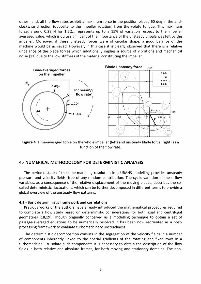
Complementarily, the evaluation of the forces in the impeller provides a good idea of the effects of the unsteadiness on the mechanical stability. Figure 4 (left) shows the steady total force on the whole impeller for different flow rates in a polar representation. It can be observed how the force turns in the anti‐clockwise direction (opposite to the impeller rotation), growing in magnitude for increasing flow rates (maximum value of 1.85 N for 1.5 Qn), and always pointing from the volute tongue towards the left on that figure. This reveals the definitive impact of the volute tongue over the impeller flow. Additional insight is provided studying the unsteady forces in the rotating blades.
Additional insight is provided studying the unsteady forces in the rotating blades, representing the temporal evolution (for one complete evolution in the relative frame) of the force on a given blade in the plot on the right of figure 4. The effect of the flow rate conditions is also analyzed. The force vector, for a given position, would be the one formed by the origin of the representation and a given position on the graph (i.e. a representative force has been plotted for the lowest flow rate when the blade is 90 deg from the volute tongue position). Double‐lobed shapes are obtained for all flow rates, with an envelope that grows as the flow rate is increased. Due to the interaction with the tongue, there is a change in the force trend in the region where the blade and the volute tongue are one in front of each other, revealed with a minimum and an inflection point. On the
8
other hand, all the flow rates exhibit a maximum force in the position placed 60 deg in the anti‐clockwise direction (opposite to the impeller rotation) from the volute tongue. This maximum force, around 0.28 N for 1.5Qn, represents up to a 15% of variation respect to the impeller averaged value, which is quite significant of the importance of the unsteady unbalances felt by the impeller. Moreover, if these unsteady forces were of circular shape, a good balance of the machine would be achieved. However, in this case it is clearly observed that there is a relative unbalance of the blade forces which additionally implies a source of vibrations and mechanical noise [11] due to the low stiffness of the material constituting the impeller.
Figure 4. Time‐averaged force on the whole impeller (left) and unsteady blade force (right) as a
function of the flow rate.
4.‐ NUMERICAL METHODOLOGY FOR DETERMINISTIC ANALYSIS
The periodic state of the time‐marching resolution in a URANS modelling provides unsteady pressure and velocity fields, free of any random contribution. The cyclic variation of these flow variables, as a consequence of the relative displacement of the moving blades, describes the so‐called deterministic fluctuations, which can be further decomposed in different terms to provide a global overview of the unsteady flow patterns. 4.1.‐ Basic deterministic framework and correlations
Previous works of the authors have already introduced the mathematical procedures required to complete a flow study based on deterministic considerations for both axial and centrifugal geometries [18,19]. Though originally conceived as a modelling technique to obtain a set of passage‐averaged equations to be numerically resolved, it has been now reoriented as a post‐processing framework to evaluate turbomachinery unsteadiness.
The deterministic decomposition consists in the segregation of the velocity fields in a number of components inherently linked to the spatial gradients of the rotating and fixed rows in a turbomachine. To isolate such components it is necessary to obtain the description of the flow fields in both relative and absolute frames, for both moving and stationary domains. The non‐

9
uniformities in each reference frame are the fluctuations respect to the time‐averaged value, so the starting point is the definition of the time‐averaging operator in both frames:
( ) ( )
1
1( , , ) ( , , , )
BNS S
i i nnB
u r z u r z tN
(7)
( ) ( )
1
1( , , ) ( , , , )
VNR R
i i n nnV
u r z u r t z tN
(8)
where (S) and (R) stand for the absolute (Stator) and relative (Rotor) frames, the tilde symbol represents the time‐averaged value and NB and NV are the number of time steps (or the sampling rate case of the experimental data) per blade passing period and vane passing period respectively. In the present configuration, a vaneless squirrel cage fan, NV is simply the unity, matching obviously with the passing of the volute tongue in the relative frame. The operator is applied for each velocity component, unsteady but randomless, due to the Reynolds‐averaging methodology employed in the original CFD data (note the overbar in the velocity components in equations 1,2). In addition, the discrete formulation of the deterministic framework has been intentionally expressed here, due to the discrete, finite number of time steps employed in the simulations. To translate absolute velocities into the relative frame, it is necessary to relocate the
rotating coordinates of the rotor into the stator coordinate system, according to ( ) ( )S R t . The deterministic fluctuation for both reference frames is therefore obtained as:
( ) ( ) ( )( , , , ) ( , , , ) ( , , )S S Si n i n iU r z t u r z t u r z (9)
( ) ( ) ( )( , , , ) ( , , , ) ( , , )R R Ri n n i n n i nU r t z t u r t z t u r t z (10)
A final additional averaging is needed to obtain the description of the throughflow, which is
based on the inherent annular geometry of turbomachines. To that end, a circumferentially averaged axisymmetric flow is identified by means of a pitch‐averaging operator, which provides a chordwise distribution of the velocity field, independent of the reference frame (theta coordinate is swept out in the averaging). Because in the present study we are dealing with blade‐to‐blade sections, it is necessary to distinguish between bladed and non‐bladed zones. In non‐bladed regions, the circumferential averaging is performed over the whole perimeter of the fan, whereas for bladed regions, the averaging must be evaluated in the volume of flow contained between the pressure and the suction sides of two consecutive blades [15]. This can be easily solved
introducing a blockage factor (R) [13] that takes into account the solidity of moving blades (this factor is equal to one in non‐bladed regions and equal to zero in bladed positions):
( ) ( )
1( , ) ( , , )
2
Naxi S
i inR
BU r z u r z where
2R
BN (11)
Nθ denotes the number of circumferential points per blade passage (the spatial discretization
between consecutive blades sides). Because the axisymmetric component is independent of the tangential coordinate, the distribution must be the same in both absolute and relative frames. Finally, the difference between the steady maps and the pitch‐averaged distributions provides the spatial non‐uniformities related to blade‐to‐blade (relative) and volute tongue (absolute) gradients:
( ) ( ) ( )( , , ) ( , , ) ( , )S S axii i iU r z u r z U r z (12)
( ) ( ) ( )( , , ) ( , , ) ( , )R R axii n i n iU r t z u r t z U r z (13)

10
Under no interaction, the fluctuations in one reference frame are strictly due to the passing
non‐uniformities in the counterpart reference frame, so circumferential (spatial) gradients are directly identified with moving (temporal) fluctuations according to t . However, in
single‐stage turbomachinery environment, due to the reduced gaps involved, there are always additional (non‐linear) interactions, that must be taken into account in one reference frame or in the other. Introducing directly this component in both reference frames, it yields:
( ) ( ) ( )( , , , ) ( , , ) ( , , )S R S
i n i n i nU r z t U r t z U r t (14) ( ) ( ) ( )( , , , ) ( , , ) ( , , )R S R
i n n i i n nU r t z t U r z U r t t (15)
In summary, the deterministic velocity field (the fluctuations at the blade passing frequency)
can be expressed as the contribution of four different components: The axisymmetric throughflow ( )axiiU (a), which is a chordwise distribution of the averaged velocity (steady), independent of the
tangential coordinate and the reference frame; both spatial blade‐to‐blade gradients ( )RiU (b) and
volute‐tongue non‐uniformities ( )SiU (c), velocity fluctuations that each one is steady in time when
referred to their own reference frame; and a pure temporal term iU (d), phase dependent
impeller‐tongue interaction representing non‐linear contributions in the velocity oscillations. This can be expressed according to:
( ) ( ) ( ) ( ) ( )
throughflow volute non-uniformities blade-to-blade gradients unsteady interaction
( , , , ) ( , ) ( , , ) ( , , ) ( , , , )S axi S R Si n i i n i nu r z t U r z U r z U r t z U r z t (16)
Additionally, the deterministic fluctuations of the velocity components in a general 3D, unsteady flow, contribute to the deterministic stress tensor in a similar fashion as the Reynolds stress tensor of the turbulent components (eq. 3). Thus, shear deterministic stresses are computed unsteadily as the temporal crossed‐products of the velocity periodic components, according to:
,( ) ( ) ( ) ( ) ( ) ( ) ( )( , , , )Det S S S S S S Sij n i j i i j jr z t U U u u u u (17)
,( ) ( ) ( ) ( ) ( ) ( ) ( )( , , , )Det R R R R R R Rij n n i j i i j jr t z t U U u u u u (18)
Note that these deterministic variables can be computed in either absolute or relative frames depending on the observer’s point of view. The time‐averaged value of these shear stresses leads to the definition of the deterministic stress tensor, which main diagonal can be added to define the deterministic kinetic energy (in both frames):
( ) ( ) ( )1( , , )
2S S S
D i iK r z U U ( ) ( ) ( )1( , , )
2R R R
D i iK r z U U (19)
Similarly, the turbulent kinetic energy, defined as the temporal evolution of the turbulent shear stresses in the main diagonal, can be time‐averaged, in resemblance with the previous deterministic energy, to provide a mean‐time footprint of the turbulent scales in the flow structures (either absolute or relative), according to:
( ) 1( , , )
2S
T i iK r z u u ( ) ( ) ( )1
( , , )2
R R RT i iK r z u u (20)
11
4.2.‐ Interpolation grid and relocating operations The sliding mesh technique implemented by most of the commercial codes based on the finite volume method provides the temporal evolution of impeller rotating cells in the relative frame and volute stationary cells in the absolute frame. Thus, to segregate the unsteady velocity field into all the deterministic components, it is necessary to translate this amount of information to a common reference frame, i.e, obtaining the velocity field in the absolute frame within the impeller passages and/or converting the absolute velocity field in the volute to the relative frame. To perform such rearrangement, it is necessary to complete a phase‐lag operator that relocates the velocity fields of incoming time steps in the “frozen” grid associated to the relative frame [28].
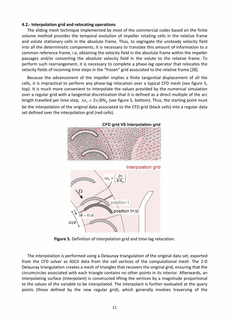
Because the advancement of the impeller implies a finite tangential displacement of all the cells, it is impractical to perform any phase‐lag relocation over a typical CFD mesh (see figure 5, top). It is much more convenient to interpolate the values provided by the numerical simulation over a regular grid with a tangential discretization that it is defined as a direct multiple of the arc length travelled per time step, 2 Bx BN (see figure 5, bottom). Thus, the starting point must
be the interpolation of the original data associated to the CFD grid (black cells) into a regular data set defined over the interpolation grid (red cells).
Figure 5. Definition of interpolation grid and time‐lag relocation.
The interpolation is performed using a Delaunay triangulation of the original data set, exported from the CFD solver as ASCII data from the cell vertices of the computational mesh. The 2‐D Delaunay triangulation creates a mesh of triangles that recovers the original grid, ensuring that the circumcircles associated with each triangle contains no other points in its interior. Afterwards, an interpolating surface (interpolant) is constructed lifting the vertices by a magnitude proportional to the values of the variable to be interpolated. The interpolant is further evaluated at the query points (those defined by the new regular grid), which generally involves traversing of the
12
triangulation data structure to find the triangle that encloses the query point. Finally, once the point is found in the corresponding triangle, the interpolated value is computed using one of the typical 2‐D interpolation methods (in this case a classic linear algorithm), respect to the triangle vertices. Note that after the interpolation, all the data coming from the solver is defined in a regular, fixed grid (i.e, with no rotating cells, in contrast to the sliding cells of the impeller), so all the velocity fields are automatically transferred to the absolute frame.
The procedure is completed performing the final phase‐lag relocation that provides the required relative fields. To convey this idea, figure 5 (bottom) shows the displacement of one rotating blade from its initial position (light grey) at an instant t, to the following location (dark
grey) once one time step (t) has passed. If the interpolation grid is such that the blade travels an exact number of cells in the tangential direction per time step, it is simple to obtain the relative frame repositioning circumferentially the values of the following time step in the previous tangential position according to:
( ) ( )( , , , ) ( , , , )R Si iu r t z t u r z t (21)
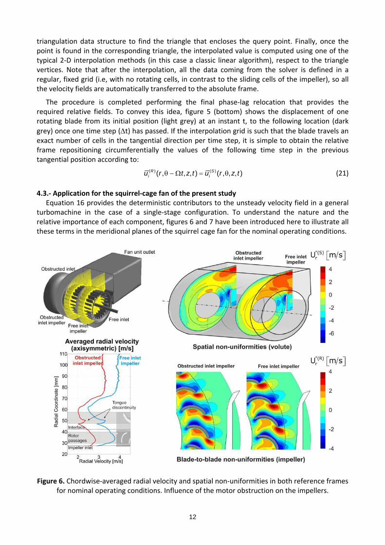
4.3.‐ Application for the squirrel‐cage fan of the present study Equation 16 provides the deterministic contributors to the unsteady velocity field in a general turbomachine in the case of a single‐stage configuration. To understand the nature and the relative importance of each component, figures 6 and 7 have been introduced here to illustrate all these terms in the meridional planes of the squirrel cage fan for the nominal operating conditions.
Figure 6. Chordwise‐averaged radial velocity and spatial non‐uniformities in both reference frames
for nominal operating conditions. Influence of the motor obstruction on the impellers.

13
First of all, figure 6 shows the first three components for the radial velocity, shown in its dimensional form, to be compared respect to the overall mean value. At the bottom, the left plot reproduces the axisymmetric flow (throughflow), revealed as a chordwise distribution in both impellers. The results for the free impeller (blue curve) show a higher mean value of the distribution than the obstructed one, as expected from previous works reporting a 60‐40% ratio of the total flow rate for the squirrel‐cage fan [20]. Additionally, the flow non‐uniformities in both reference frames are also illustrated in the figure. The 3D view on top shows the circumferential gradient associated to the volute flow in the absolute frame, showing that the machine perimeter can be taken as the characteristic length scale for the absolute frame of reference. Moreover, the effect of the volute tongue is clearly visible as a significant reduction (blue zones with high negative oscillation) of the radial velocity, associated to the stagnated conditions of the flow. Note the large region of high velocity (red zones) in the case of the free inlet impeller. To conclude, the zoom view in the vicinity of the tongue, obtained in the relative reference frame, reveals the blade‐to‐blade gradients, which are circumferentially periodic from passage to passage. Regions of minimum values are associated to severe recirculation zones and detached flow conditions, while maximum values indicate a concentration of velocity, thus identifying the classic jet‐wake structure for centrifugal impellers. Also note that the overall range of variation (between ‐4 and 4 m/s) is in the order of the chordwise‐averaged value, confirming the relevance of the spatial gradients on the flow.
Figure 7. Pure unsteady component of blade‐tongue interaction for nominal operating conditions. Influence of the motor obstruction on the impellers.
The final deterministic component for the radial velocity, including the pure temporal
interaction at one particular instant for nominal conditions, is shown in figure 7. This remaining unsteady part contains only the effect of the periodic influence of the volute tongue on the impeller flow. The dominant role of the stagnation conditions close to the volute tongue is observed for both impellers, being more evident for the one at the motor side. Moreover, the relative small size of the impellers derives in a higher impact of this component over the impeller flow, compared to previous typical centrifugal pumps studied by the authors [19], thus resulting in the appearance of this component in the whole circumferential direction. Positive and negative values, rotating tangentially in‐phase, reveal the periodic oscillation coming from the blockage effect induced by the tongue over the relative flow within the impeller passages. Notice that this component is notably important, as it can be observed from its value with respects to the other components, once again in the range between ‐4 and 4 m/s.

14
The conclusion is that for this kind of turbomachines, the pure unsteady interaction is a key factor in the description of the 3D internal flow. If neglected, assuming for instance a steady methodology for the resolution of the flow (like a mixing plane or a frozen rotor technique), the description of the flow obtained numerically would be meaningless. Furthermore, as the component is clearly affecting the whole annulus, even a steady analysis including a limited source term that could be eventually modeled only in the vicinity of the volute tongue would be also an inaccurate choice for the present turbomachine. In fact, this was already observed experimentally by the authors in previous investigations [11], where the aerodynamic noise generation was found to be clearly under predicted using noise sources only coming from the tongue area. 4.4.‐ On the deterministic contributors to the blade forces
The real importance of the deterministic decomposition and the identification of the pure unsteady component is that, with this post‐processing framework, we have at our disposal an interesting tool to quantify the level of interaction between fixed and moving flow structures, otherwise immersed in the overall unsteadiness intensity. Up to now, we have already realized that for this geometry, and even at nominal conditions, we cannot perform simulations of the impeller and volute geometries independently and retrieve the final unsteady description merging the separate results because a full‐unsteady scheme using a sliding mesh technique is mandatory.
Now in order to understand how the different flow structures, previously isolated in the deterministic decomposition, are related to the unsteady forces on the impeller blades, we have tried to move forward the analysis in the present investigation focusing on the influence of every flow pattern in the total unsteady forces. Hence, to bring the gap between velocity fields and blade forces, we have introduced a simplified two‐dimensional control volume analysis over an impeller blade to compute the unsteady force overtime. Assuming steady flow in the impeller passages in the relative frame, the force can be simply evaluated as the change in the momentum between the impeller outlet and impeller inlet, according to:
( ) ( ) ( )
, ,1
( )N
R R Rb x x x n
nSC
F u u dS mu
( ) ( ) ( )
, ,1
( )N
R R Rb y y y n
nSC
F u u dS mu (22)
where the integral is replaced by the summation over the blade pitch, N, and the contribution of every velocity component to the total unsteady force can be easily evaluated introducing the corresponding deterministic field in equation 22. To provide an order of accuracy with this formulation, a comparison of the total unsteady force computed numerically with the CFD solver over the blades of the free impeller (figure 4, right) and the value estimated with the unsteady relative velocity introduced in equation 22 has been done. The differences have been analyzed in terms of discrepancies between the maximum forces and also the associated directions for all the flow rates studied (see table 2), showing admissible maximum deviations in the order of 4 to 8%.
Table 2. Accuracy in the estimation of unsteady blade forces using a 2‐D simplified CV analysis
Case ( )max
CFDF N
( )max
CVF N
%Fe ( )maxCFD ( )
maxCV %e
0.6 Qn 0.070 0.072 2.8 160 147 8.1
Qn 0.125 0.118 5.6 140 134 4.3
1.5 Qn 0.246 0.257 4.3 130 135 3.8

15
5.‐ RESULTS ANS DISCUSSION
Following, the different velocity terms addressed in the deterministic decomposition are analyzed as a function of the volumetric flow rate and the impeller conditions (free inlet or obstructed inlet). The main goal is to observe how off‐design conditions present an impact on the different flow patterns regarding impeller passages and volute profile. 5.1.‐ Spatial non‐uniformities in the volute (absolute frame)
The first step is the analysis of the averaged structure around the volute profile at the impeller outlet, shown for the radial velocity in figure 8. The spatial distribution has been made non‐dimensional with the mean radial velocity at the impeller exit for each operating condition
( 2 2rU Q D b ). As expected, maximum deviations from averaged radial outlet flow, that is,
maximum positive and negative values of the non‐uniformities are found in the proximity of the volute tongue. Positive values are found in the circumferential range covering those zones before entering into the volute tongue, which indicates the main path of the bulk flow to enter into the discharge conduits. At nominal conditions, the guidance seems to be optimal, whereas at low and high flow rates both underturning and overturning streamlines reveal the out‐of‐design operation mode of the volute. Additionally, negative values are found after passing the tongue (dark blue zones, especially for the off‐design flow rates) revealing how the stagnation conditions are particularly influenced by the operating conditions, and rotating clockwise as the flow rate increases. This result is clearly in consonance with the averaged force over the whole impeller in figure 4 (left), which also rotates clockwise, increasing the mean value as the flow rate is increased. This trend confirms that the time‐averaged force over the whole impeller is provoked by the tangential non‐uniformities of the volute in the fixed reference frame, especially associated to the pressure discontinuity induced in the stagnation point within the tongue regions.
Figure 8. Spatial non‐uniformities in the volute flow as a function of the flow rate.
Figure 9. Differences in the spatial non‐uniformities between free and obstructed impellers.
16
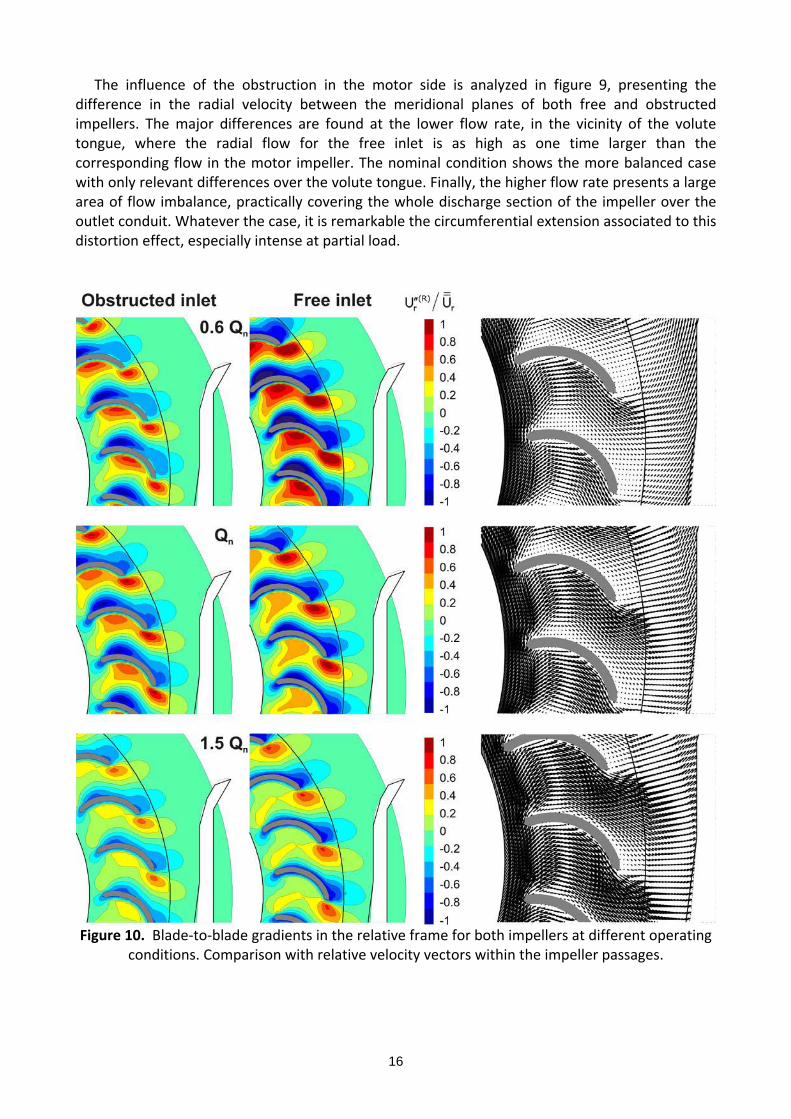
The influence of the obstruction in the motor side is analyzed in figure 9, presenting the difference in the radial velocity between the meridional planes of both free and obstructed impellers. The major differences are found at the lower flow rate, in the vicinity of the volute tongue, where the radial flow for the free inlet is as high as one time larger than the corresponding flow in the motor impeller. The nominal condition shows the more balanced case with only relevant differences over the volute tongue. Finally, the higher flow rate presents a large area of flow imbalance, practically covering the whole discharge section of the impeller over the outlet conduit. Whatever the case, it is remarkable the circumferential extension associated to this distortion effect, especially intense at partial load.
Figure 10. Blade‐to‐blade gradients in the relative frame for both impellers at different operating
conditions. Comparison with relative velocity vectors within the impeller passages.
17
5.2.‐ Blade‐to‐blade gradients in the impeller passages (relative frame) The blade‐to‐blade distribution of the flow patterns in the relative frame is an excellent
indicator to analyze the level of disorder of the flow within the impeller passages and, as an extension, of the goodness of the energy transfer achieved in the blades. Figure 10 shows the evolution of these gradients with the operating conditions for both obstructed and free impellers. Notice how the large aerodynamic loads in the blades are perfectly recovered in the representation of this component for the lowest flow rate. Large separations and recirculation vortices are found as dark blue regions in the suction side of the blades, whereas impinging jets and high velocity regions at the pressure side indicate ordered out coming flow structures. To understand the complexity and three‐dimensionality of the flow within the impellers, mainly due to the severe geometrical constraints imposed by the extremely short‐chord blades, a representation of the time‐averaged vector field within the impeller (relative frame) is also shown in figure 10. It is remarkable the direct correspondence between the vortical structures exhibited by the vectors and the spatial gradients of the blade‐to‐blade maps. In all the cases, the relative streamlines followed by the vector field reveal that only a minimum portion of the blade passage presents an acceptable guidance. In particular, once the early separation induced by the relative inlet flow angle is progressively reduced (approximately at midchord), the flow suffers again an excessive overturning, due to the drastic curvature of the blades. Consequently, the flow is concentrated towards the pressure side of the trailing edges provoking a large jet‐wake structure, with an intense separation and generation of aerodynamic losses. These patterns are characteristic of this type of squirrel cage fans, being more evident at low flow rates. Respect to the differences between the free impeller and the obstructed one in the motor side, it is noticeable the higher separation induced in the suction side of the blades in the case of the obstructed impeller (left column in figure 10). On the contrary, the outflow separation is less dramatic than for the free impeller. 5.3.‐ Unsteady tongue‐impeller interaction
The analysis of the unsteady tongue‐impeller interaction is the key point of the present investigation. In figure 7, a snapshot of this component at t/TR=0.1 was included in the decomposition process to introduce its typical characteristics. Now, in figure 11, more insight is devoted regarding the nature of the oscillations involved in this pure unsteady interaction. In particular, the figure shows the temporal evolution of the radial component at the free‐inlet impeller outlet in case of nominal conditions. As in figure 3, the circumferential section of the impeller discharge has been converted into a planar, rectangular domain, representing the impeller width in the ordinates and the impeller perimeter in the abscissa. Thus, in this transversal plane, it is possible to observe the distribution of the interaction in the spanwise direction.
Five intermediate snapshots during a blade passing period (TR) have been represented to illustrate the periodic interaction of the stagnation conditions of the tongue over the wake fluid coming from the impeller. The positive‐negative oscillation (associated to every pressure side‐suction side structure in the blades passages) moves tangentially in phase with the rotor, being
particularly intense in those regions close to the volute tongue ( = 22.5 deg). It is also noticeable that every angular location experiences a complete periodic oscillation over the rotor blade passing period. The origin of these positive and negative fluctuations is associated to the periodic effect of the impeller passages (23 for the whole perimeter of each impeller): low velocity fluctuations are usually linked to the oscillation of the impeller wakes due to the volute tongue asymmetry or even to the interference with the low velocity regions associated to the blades pressure side. Additionally, regions of high velocity fluctuations are linked to a recovery of the tangential velocity in the blades suction side [19].

18
At t/TR=0.6, a white‐dashed line has been traced over the limits of the blades oscillations to highlight the external regions of the impeller which appear to be less conditioned by this component. Notice that between 120 deg and 300 deg (approximately the same region that was shown to be practically unaffected by the stagnations conditions of the volute flow in the central map in figure 8), the interaction is notably reduced. At 240 deg it is also observed a reinforcement of this component in the external locations (marked with a white‐dashed circle), revealing a sort of geometrical distortion for such position that derives in a high interaction area.
Figure 11. Temporal evolution of the pure interaction (non‐linear) component (Qn).
To analyze the effect of the operating conditions on the intensity of the tongue‐impeller
interaction, we have introduced the RMS value of rU in longitudinal planes for the free‐inlet and
motor‐side impellers in figures 12 and 13. With this metric, it is possible to reduce the temporal evolution of this component into just one representative map for each flow condition. As a consequence, the positive‐negative oscillations advanced in previous figure 7 turn now into regions of positive values representing the maximum averaged intensity of the interaction.
As expected, this pure interaction is mainly limited to those zones in the vicinity of the volute tongue, being more important at off‐design conditions. In particular, in the case of the free‐inlet impeller, the component is concentrated in the front region of the volute tongue, slightly advancing clockwise as the flow rate increases. At intermediate tangential locations (between 120 deg and 300 deg), it is observed a reduction of this component, but it cannot be neglected in any case. This evidence is significant because gives a precise idea of the important unsteady interactions, which are a clear source of aerodynamic noise and overall disturbance, resulting in a detrimental characteristic of these small fan units [11], even for nominal conditions. In the case of higher flow rates, the interaction is again reinforced (in terms of affected zones), affecting all the impeller region facing the discharge conduit.
It is noticeable that all the interaction is strictly limited to the impeller passages, thus revealing that the blade wakes have no influence on the stagnation conditions of the volute. Therefore, the interaction can be described in terms of just one‐way interaction, from the volute to the impeller flow, manifested as a clear potential mechanism of the flow. In other words, no viscous

19
mechanisms are significant to describe interaction phenomena in this type of squirrel‐cage fans. Additionally, focusing on the radial distribution of the RMS value, it can be observed that the interaction is more evident in both leading edge and trailing edge zones of the impeller, being even more intense for the inflow that for the outflow in the case of nominal and high flow rates. This result points out the lack of space in the fan unit, the severe impact produced by the volute tongue over the fan impeller, extremely conditioning the inlet flow characteristics, and the high blockage that leads to a deficient flow guiding with a highly distorted primary flow susceptible for early separation and stall [2].
The maps for the motor‐side in figure 13 are similar and analogous conclusions can be drawn from the discussion of the distributions. Basically, the interaction zones are equivalent and reinforced respect to the free‐inlet impeller, especially at high flow rate, with a slight tendency to initiate the interaction at earlier circumferential positions.
Figure 12. RMS values for the pure interaction in the free‐inlet impeller at different flow rates.
Figure 13. RMS values for the pure interaction in the motor‐side impeller at different flow rates.
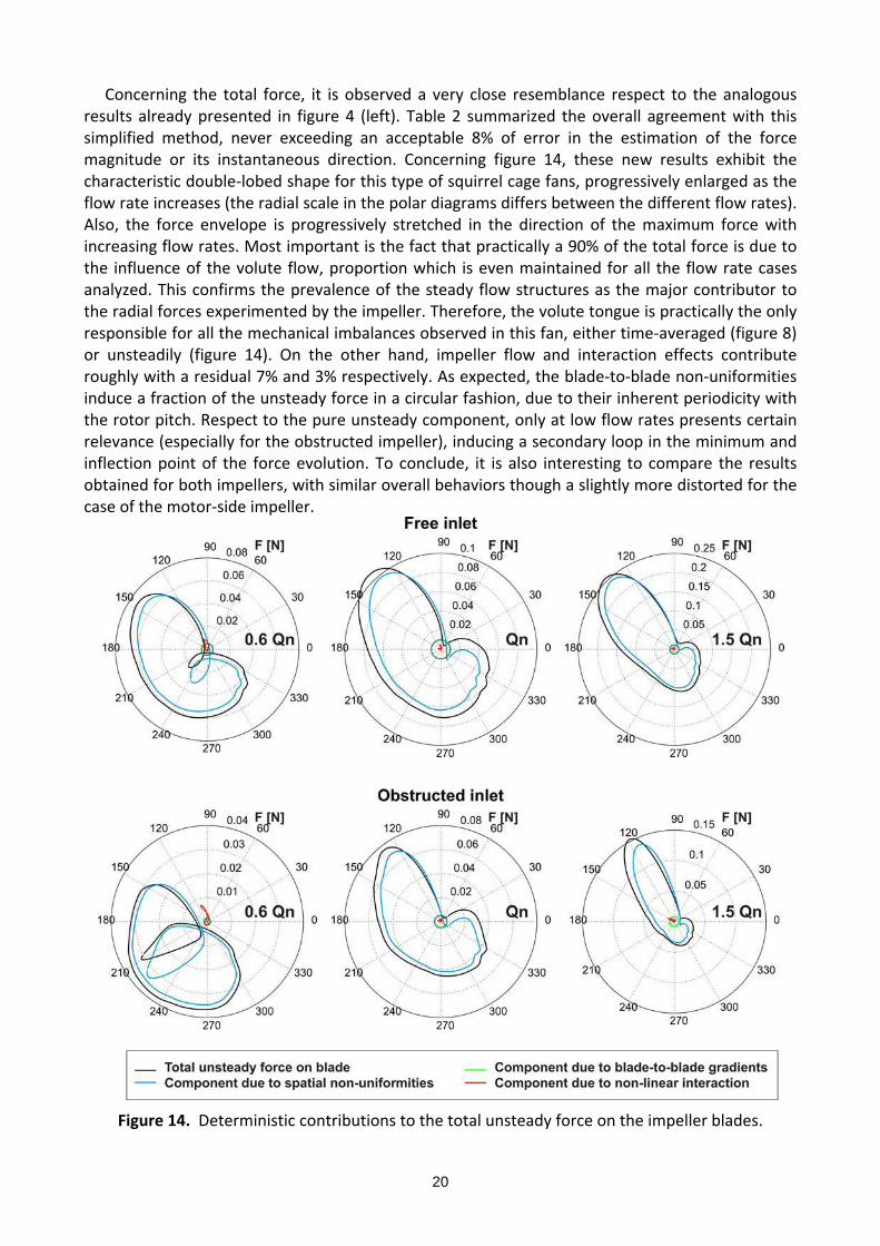
5.4.‐ On the nature of the unsteady blade forces The evaluation of blade forces using a simplified method to segregate the relative weight of all the deterministic components in the impeller may help to estimate which is the most important flow pattern regarding mechanical vibrations. Figure 14 shows the estimation of the total unsteady force over an impeller blade for a complete rotor revolution (black line), and the contribution of the different components: the volute flow (blue line), the impeller flow (green line) and the pure unsteady interaction (red line). The analysis is performed for both free‐inlet and motor‐side impellers, including the influence of the operating conditions on the results.
20
Concerning the total force, it is observed a very close resemblance respect to the analogous results already presented in figure 4 (left). Table 2 summarized the overall agreement with this simplified method, never exceeding an acceptable 8% of error in the estimation of the force magnitude or its instantaneous direction. Concerning figure 14, these new results exhibit the characteristic double‐lobed shape for this type of squirrel cage fans, progressively enlarged as the flow rate increases (the radial scale in the polar diagrams differs between the different flow rates). Also, the force envelope is progressively stretched in the direction of the maximum force with increasing flow rates. Most important is the fact that practically a 90% of the total force is due to the influence of the volute flow, proportion which is even maintained for all the flow rate cases analyzed. This confirms the prevalence of the steady flow structures as the major contributor to the radial forces experimented by the impeller. Therefore, the volute tongue is practically the only responsible for all the mechanical imbalances observed in this fan, either time‐averaged (figure 8) or unsteadily (figure 14). On the other hand, impeller flow and interaction effects contribute roughly with a residual 7% and 3% respectively. As expected, the blade‐to‐blade non‐uniformities induce a fraction of the unsteady force in a circular fashion, due to their inherent periodicity with the rotor pitch. Respect to the pure unsteady component, only at low flow rates presents certain relevance (especially for the obstructed impeller), inducing a secondary loop in the minimum and inflection point of the force evolution. To conclude, it is also interesting to compare the results obtained for both impellers, with similar overall behaviors though a slightly more distorted for the case of the motor‐side impeller.
Figure 14. Deterministic contributions to the total unsteady force on the impeller blades.
21
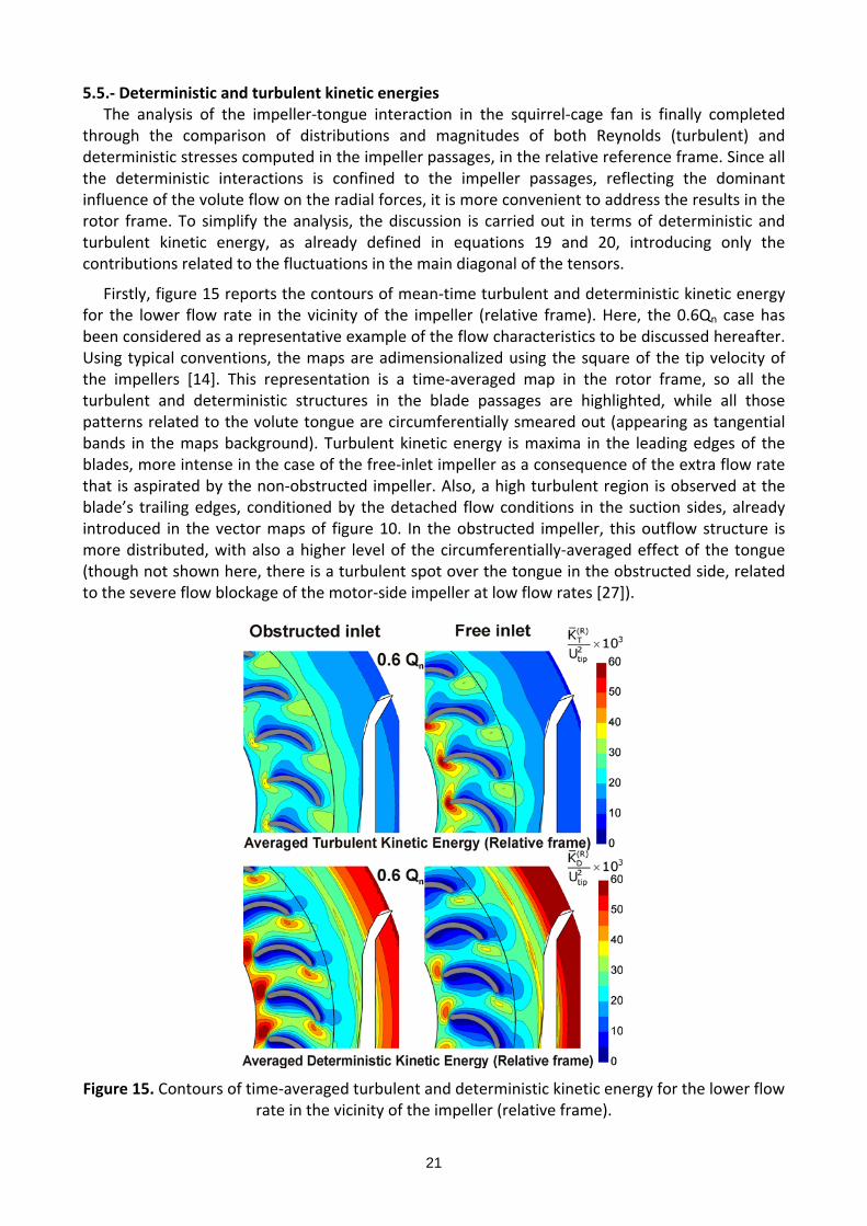
5.5.‐ Deterministic and turbulent kinetic energies The analysis of the impeller‐tongue interaction in the squirrel‐cage fan is finally completed
through the comparison of distributions and magnitudes of both Reynolds (turbulent) and deterministic stresses computed in the impeller passages, in the relative reference frame. Since all the deterministic interactions is confined to the impeller passages, reflecting the dominant influence of the volute flow on the radial forces, it is more convenient to address the results in the rotor frame. To simplify the analysis, the discussion is carried out in terms of deterministic and turbulent kinetic energy, as already defined in equations 19 and 20, introducing only the contributions related to the fluctuations in the main diagonal of the tensors.
Firstly, figure 15 reports the contours of mean‐time turbulent and deterministic kinetic energy for the lower flow rate in the vicinity of the impeller (relative frame). Here, the 0.6Qn case has been considered as a representative example of the flow characteristics to be discussed hereafter. Using typical conventions, the maps are adimensionalized using the square of the tip velocity of the impellers [14]. This representation is a time‐averaged map in the rotor frame, so all the turbulent and deterministic structures in the blade passages are highlighted, while all those patterns related to the volute tongue are circumferentially smeared out (appearing as tangential bands in the maps background). Turbulent kinetic energy is maxima in the leading edges of the blades, more intense in the case of the free‐inlet impeller as a consequence of the extra flow rate that is aspirated by the non‐obstructed impeller. Also, a high turbulent region is observed at the blade’s trailing edges, conditioned by the detached flow conditions in the suction sides, already introduced in the vector maps of figure 10. In the obstructed impeller, this outflow structure is more distributed, with also a higher level of the circumferentially‐averaged effect of the tongue (though not shown here, there is a turbulent spot over the tongue in the obstructed side, related to the severe flow blockage of the motor‐side impeller at low flow rates [27]).
Figure 15. Contours of time‐averaged turbulent and deterministic kinetic energy for the lower flow rate in the vicinity of the impeller (relative frame).

22
To compare turbulent structures with the unsteady features of the flow, we can analyze now the results in the bottom maps of the figure. In essence, the deterministic stresses are generated as a consequence of the dynamics of the circumferential non‐uniformities of the impeller or even by a periodic modulation of the flow variables in a particular region of the volute flow [18]. The order of magnitude of the deterministic kinetic energy is found to be similar to the turbulent energy, with a notable correspondence between the maps of turbulent kinetic energy and these ones of deterministic contributions, indicating that zones with maximum interactions are also affected with high level of turbulent generation. However, the trend is reversed respect the impeller that it is analyzed: now, deterministic energy is notably higher for the motor‐side impeller than for the free inlet one. Anyway, the most relevant characteristic of the deterministic maps is the presence of a high‐level tangential band of deterministic energy in the volute tongue. Associated to a fixed element, this deterministic source is tangentially‐averaged when translated to the relative frame. Since no deterministic fluctuations were observed close to the volute tongue in the radial component (figures 6 and 7), this unsteadiness must come from the periodic fluctuation of the tangential velocity in the vicinity of the tongue.
Because of the pitch periodicity presented in the results of previous figure 15, an additional pitch‐averaging can be easily introduced to obtain a quantitative value of the radial distribution of the both turbulent and deterministic structures. This allows a better description of the levels as the passages and volute are travelled by the flow and facilitates the comparison between the different flow rates. To that end, figure 16 plots the radial evolution of the pitch‐averaged turbulent kinetic energy for both impellers as a function of the operating conditions and figure 17 the deterministic kinetic energy. In figure 16, it is clearly observable the progressive decay of the turbulence generation with the radial coordinate, with the maxima placed in the stagnation conditions of the blade’s leading edges. In addition, higher the flow rate, higher the turbulent levels within the impeller passages, because of the fact that dissipative phenomena involved within the turbulence are reinforced with larger flow rates. Complementarily, figure 17 shows how the deterministic energy is increased towards the volute tongue in the relative frame. Here, the distribution of the nominal flow rate (thin black line) is the less energetic as corresponds with the idea that close to design conditions, the interaction must be the lowest [19].
Figure 16. Radial distribution of pitch‐averaged
turbulent kinetic energy (relative frame). Figure 17. Radial distribution of pitch‐averaged deterministic kinetic energy (relative frame).

23
CONCLUSIONS
This paper presents a numerical methodology to segregate between relative and absolute flow structures and address the impact of unsteadiness and impeller‐tongue interaction in the operation of centrifugal fans. The novelty is based on the employment of deterministic correlations to perform the analysis of the flow in blade‐to‐blade planes for radial turbomachinery. Previous numerical results, obtained with a viscous 3D unsteady solver, are used as a time‐resolved database for the numerical routines defined in the paper. Afterwards, interpolation and relocating operations of the velocity fields between CFD meshes and post‐processing grids are presented and performed for different flow rates of a squirrel cage fan.
The decomposition of the deterministic unsteadiness into a pure temporal interaction and a rotating spatial non‐uniformity (linked to the impeller) has proven to be a useful framework for investigating the periodic impeller‐tongue interaction that is established inside this kind of small fan units. Moreover, the results obtained with this computational tool have provided a notable advancement in the physical comprehension of the complexity, three‐dimensionality and unsteadiness of the flow structures in the interaction regions of centrifugal fans. Additionally, the different deterministic contributors to the unsteady forces on the blades have been also assessed, allowing an estimation of the relevance of the different components into the total unsteady scenario.
In particular, concerning the obtained results, it has been observed the influence of the different operating conditions over the volute flow, in terms of location and intensity of the stagnation point in the tongue. Also, the analysis of the blade‐to‐blade gradients in the impeller illustrated the features of the jet‐wake structure and the deficiencies related to flow guidance, separation regions and generation of aerodynamic losses. Respect to the unsteady interaction between the impeller and the volute tongue, it was shown the dominant role of the tongue over the impeller blades. RMS values of this component revealed the location of major interactions within the centrifugal fan, mainly concentrated towards the impeller passages in the vicinity of the tongue region. Also, the analysis of the unsteady forces on the impeller blades has permitted to conclude that the volute tongue non‐uniformity is practically the only responsible for all the mechanical imbalances observed in this fan, either time‐averaged or instantaneously. Finally, distributions of deterministic kinetic energy in the relative frame revealed significant similarities with the turbulent structures for those phenomena correlated with the blade passing frequency, and pointed out the inaccurate performance of the flow at both leading and trailing edges of the blades.
In summary, this study demonstrates the importance of performing full‐unsteady simulations to capture accurately the internal flow structures for this kind of centrifugal fans. Even for nominal conditions, the pure unsteady interaction is as important as the volute non‐uniformities or the blade‐to‐blade gradients obtained in both absolute and relative frames of reference. Additionally, all the results indicate that future designs for this type of squirrel cage fans must reconsider some geometrical modifications near the volute tongue in order to reduce significantly the levels of fluid dynamic interaction, and therefore the generation of aerodynamic noise and pressure pulsations (tonal noise). Furthermore, the numerical methodology presented here has proved its ability as a valuable computational tool for researchers and designers in the field of turbomachinery, interested to provide insight in the analysis of the internal flows and the identification of sources of rotor‐stator interaction for both diagnosis and redesign criteria of impeller and volute geometries.
24
ACKNOWLEDGEMENTS
The authors acknowledge the financial support from the “Ministerio de Ciencia e Innovación” under Project “Tecnologías ecológicas para el transporte Urbano, ecoTRANS” (CDTI).
NOMENCLATURE
b = Impeller width (m) B = Number of blades D = Impeller diameter (m) KD = Deterministic kinetic energy (m2/s2)
k, KT = Turbulent kinetic energy (m2/s2)
m = Mass flow rate (kg/s) nS = Specific speed, nS = Qn
1/2/(gHn)3/4
NB = Number of time steps per blade passing period NV = Number of time steps per vane passing period
N = Number of tangential points per blade pitch
p = Static pressure (Pa) Q, Qn = Flow rate and design flow rate (m3/h)
r = Radial coordinate (m) RNG = Renormalization Group
t = Time (s) TR = Rotor blade passing period (s)
iu = Unsteady Reynolds‐averaged velocity component (m/s)
iU = Deterministic velocity fluctuation (m/s)
iU = Spatial non‐uniformity (m/s)
iU = Pure temporal interaction (m/s)
iU = Mean‐time velocity (m/s)
iU = Overall mean velocity (m/s)
URANS = Unsteady Reynolds‐Averaged Navier‐Stokes u = Velocity vector (m/s) z = Axial coordinate (m)
Greek symbols
= Turbulent dissipation, (m2/s3).
= Angular coordinate (rad)
R = Blockage factor () = Density (kg/m3)
= Rotational speed (rpm)
= Shear stress (Pa)

25
Superscripts and subscripts
= Reynolds‐averaging
~ = Time‐averaging
axi = Pitch‐averaging
Det = Deterministic i,j,k = Radial, circumferential and axial components tip = Tip (S) = Volute (stator) reference frame (absolute) (R) = Impeller (rotor) reference frame (relative) R = Rotor 1 = Impeller inlet 2 = Impeller outlet
REFERENCES
[1] Kind RJ, Tobin MG. Flow in a centrifugal fan of the squirrel cage type. ASME J Turbomach 1990; 112: 84‐90.
[2] Cau G, Mandas N, Manfrida N, Nurzia F. Measurements of primary and secondary flows in an industrial forward‐curved centrifugal fan. ASME J Fluids Eng 1997; 109: 353‐358.
[3] Velarde‐Suárez S, Ballesteros‐Tajadura R, Santolaria‐Morros C, Pereiras‐García B. Reduction of the aerodynamic tonal noise of a forward‐curved centrifugal fan by modification of the volute tongue geometry. App Acoust 2008; 69: 225‐232
[4] Lakshminarayana B. An assessment of computational fluid dynamic techniques in the analysis and design of turbomachinery. ASME J Fluids Eng 1990; 113: 315‐352.
[5] Gunzburger MD, Nicolaides RA. Incompressible computational fluid dynamics. Trends and advances. Cambridge University Press; 1993.
[6] Lin SC, Huang CL. An integrated experimental and numerical study of forward–curved centrifugal fan. Exp Therm Fluid Sci 2002; 26: 421–434.
[7] Kim K, Seo S. Shape optimization of forward‐curved‐blade centrifugal fan with Navier‐Stokes analysis. ASME J Fluids Eng 2004; 126: 735‐742.
[8] Ballesteros‐Tajadura R, Velarde‐Suárez S, Hurtado‐Cruz JP, Santolaria‐Morros C. Numerical calculation of pressure fluctuations in the volute of a centrifugal fan. ASME J Fluids Eng 2006; 128: 359‐369.
[9] Engin T. Study of tip clearance effects in centrifugal fans with unshrouded impellers using computational fluid dynamics. Proc IMechE Part A. J Power and Energy 2006; 220: 599‐610.
[10] Velarde‐Suárez S, Ballesteros‐Tajadura R, Hurtado‐Cruz JP, Santolaria‐Morros C. Experimental determination of the tonal noise sources in a centrifugal fan. J Sound Vib 2006; 295: 781‐790.
[11] Velarde‐Suárez S, Ballesteros‐Tajadura R, González Pérez J, Pereiras‐García B. Relationship between volute pressure fluctuation pattern and tonal noise generation in a squirrel‐cage fan. App Acoust 2009; 70: 1384‐1392.
26
[12] Lin SC, Tsai ML. An integrated performance analysis for a backward‐inclined centrifugal fan. Computers & Fluids 2012; 56: 24‐38.
[13] Adamczyk JJ. Aerodynamic analysis of multistage turbomachinery flows in support of aerodynamic design. ASME J Turbomach 2000; 122: 189‐217.
[14] Meneveau C, Katz J. A deterministic stress model for rotor‐stator interactions in simulations of passage‐averaged flow. ASME J Fluid Eng 2002; 124: 550‐554.
[15] Persico G, Rebay S. A penalty formulation for the throughflow modeling of turbomachinery. Computers & Fluids 2012; 60: 86‐98.
[16] Sinha M, Katz J, Meneveau C. Quantitative visualization of the flow in a centrifugal pump with diffuser vanes. Part II: addressing passage‐averaged and large‐eddy simulation modeling issues in turbomachinery flows. ASME J Fluids Eng 2000; 122: 108‐116.
[17] Gao L, Xi G, Zhou L, Wang S. Experimental and computational investigation of a centrifugal compressor stage. Proc IMechE Part A. J Power and Energy 2005; 219: 25‐33.
[18] Fernández Oro JM, Argüelles Díaz KM, Santolaria Morros C, Blanco Marigorta E. Analysis of the deterministic unsteady flow in a low‐speed axial fan with inlet guide vanes. ASME J Fluids Eng 2008; 130: 031101‐1‐12.
[19] Fernández Oro JM, González J, Argüelles Díaz KM, Guerras Colón FI. Decomposition of deterministic unsteadiness in a centrifugal turbomachine: non‐linear interactions between the impeller flow and volute for a double suction pump. ASME J Fluids Eng 2011; 133: 011103, 1‐10.
[20] Ballesteros‐Tajadura R, Guerras Colón FI, Velarde‐Suárez S, Fernández Oro JM, Argüelles Díaz KM, González J. Numerical model for the unsteady flow features of a squirrel cage fan. ASME Paper No. FEDSM2009‐78479, Vail (USA), 2‐6 August; 2009.
[21] Freitas CJ. Journal of Fluids Engineering editorial policy statement on the control of numerical accuracy. ASME J Fluids Eng 1993; 115: 339‐340.
[22] Celik IB, Ghia U, Roache PJ, Freitas CJ, Coleman H, and Raad PE. Procedure for estimation and reporting of uncertainty due to discretization in CFD applications. ASME J Fluids Eng 2008; 130: 078001/1‐4.
[23] Roache PJ. Perspective: validation ‐ What does it mean?. ASME J Fluids Eng 2009; 130: 034503/1‐4.
[24] Schobeiri MT. Fluid Mechanics for Engineers. Springer‐Verlag Berlin Heidelberg; 2010.
[25] González J, Fernández Francos J, Blanco Marigorta E, Santolaria Morros C. Numerical simulation of the dynamic effects due to impeller‐volute interaction in a centrifugal pump. ASME J Fluids Eng 2002; 124: 348‐355.
[26] González J, Santolaria Morros C. Unsteady flow structure and global variables in a centrifugal pump. ASME J Fluids Eng 2006; 128: 937‐946.
[27] Fernández Oro JM, Velarde‐Suárez S, Guerras Colón FI, Argüelles Díaz KM, González J. Flow Analysis and Deterministic Decoupling in a Squirrel Cage Fan. ASME Paper No. AJK2011‐22059, Hamamatsu (Japan), 24‐29 July; 2011.
[28] Wang X, Chen JP. A Post–processor to render turbomachinery flows using phase–lag simulations. AIAA Paper No. 04‐615, AIAA 42nd Aerospace Sciences Meeting and Exhibit, Reno (NV); 2004.
27
LIST OF FIGURES Fig. 1. One of the twin impellers (left). Double impeller unit (right).
Fig. 2. Numerical 3D mesh (left) and detail of discretization at interfaces (right).
Fig. 3. Instantaneous (0.6Qn) and time‐averaged (Qn) pressure distributions at impeller outlet.
Fig. 4. Time‐averaged force on the whole impeller (left) and unsteady blade force (right) as a function of the flow rate.
Fig. 5. Definition of interpolation grid and time‐lag relocation.
Fig. 6. Chordwise‐averaged radial velocity and spatial non‐uniformities in both reference frames for nominal operating conditions. Influence of the motor obstruction on the impellers.
Fig. 7. Pure unsteady component of blade‐tongue interaction for nominal operating conditions. Influence of the motor obstruction on the impellers.
Fig. 8. Spatial non‐uniformities in the volute flow as a function of the flow rate.
Fig. 9. Differences in the spatial non‐uniformities between free and obstructed impellers.
Fig. 10. Blade‐to‐blade gradients in the relative frame for both impellers at different operating conditions. Comparison with relative velocity vectors within the impeller passages.
Fig. 11. Temporal evolution of the pure interaction (non‐linear) component (Qn).
Fig. 12. RMS values for the pure interaction in the free‐inlet impeller at different flow rates.
Fig. 13. RMS values for the pure interaction in the motor‐side impeller at different flow rates.
Fig. 14. Deterministic contributions to the total unsteady force on the impeller blades.
Fig. 15. Contours of time‐averaged turbulent and deterministic kinetic energy for the lower flow rate in the vicinity of the impeller (relative frame).
Fig. 16. Radial distribution of pitch‐averaged turbulent kinetic energy (relative frame).
Fig. 17. Radial distribution of pitch‐averaged deterministic kinetic energy (relative frame).
HIGHLIGHTS 1. Numerical methodology to assess absolute and relative flow structures in radial
turbomachinery unsteadiness.
2. Deterministic analysis of flow structures in blade‐to‐blade planes of centrifugal fans for the first time.
3. Volute non‐uniformities are dominant sources of unsteadiness over the impeller passages.
4. Wake fluid from the impeller has no relevance on the stagnation conditions in the volute tongue.
5. The methodology confirms the poor performance and the lack of uniformity of squirrel cage fans.

28

This document is a pre-print version of the scientific paper published by
Elsevier. It has been released by the authors to fulfill all the publisher
requirements established for Article Sharing:
https://www.elsevier.com/about/policies/sharing
© 2019. This manuscript version is made available under the Creative
Commons Attribution-NonCommercial-NoDerivatives 4.0 International License
(CC-BY-NC-ND 4.0 license)
http://creativecommons.org/licenses/by-nc-nd/4.0/