Embed Size (px)
Citation preview

University of Applied Sciences HTW Berlin, FB2
Wilhelminenhofstr. 75A, 12459 Berlin, Germany
Thermo-& Fluid dynamics group
Prof. Dr.-Ing. Stefan Frank
e-mail : [email protected]
Manoochehr Darvish , Stefan Frank
STAR European Conference 2011
March 22-23
Numerical Investigations on the
Performance Characteristic of Radial
Fans with Forward Curved Blades
by means of CFD

Agenda
Sirocco fan Introduction ◊ Applications ◊ Advantages/Disadvantages ◊ Characteristic curves
Model parameters / Modeling physics
CFD Simulations outline
Rotation modeling
Overview of the generated mesh configurations
Results ◊ Characteristic curves: CFD vs. Experiment ◊ Simulation time ◊ Steady vs. Unsteady simulations
Conclusions 3

Commonly used blade shapes in Radial fans (with their maximum attainable efficiencies)
Forward curved blades (65%)
Radial-Tip blades (70%)
Radial blades (60%)
Backward inclined Airfoil blades (92%)
Backward inclined blades (78%)
Backward curved blades (85%)
Key factors for fan type
selection:
◊ Pressure
◊ Flow rate
◊ Efficiency
◊ Noise generation
◊ Space constraints
◊ Drive configuration
◊ Cost
◊ ...
4

Sirocco fan specifications
◊ Large blade angles
◊ Small size relative to other fan types
◊ Operation at low speeds low level of noise
Flow separation between the blades
Low efficiency
Scroll housing is required
Applications:
− Automotive industry
− HVAC applications
5

Sirocco Fan Performance Curve
Region of Instability
Best Efficiency Point (BEP)
Throttle Range Overload Range
6

Model Parameters
◊ Fan wheel outer diameter (D2) :200 mm
◊ Inner/Outer diameter (D1/D2) : 0.8
◊ Number of blades : 38
◊ Rotor width : 82 mm
◊ Scroll housing width: 87 mm
◊ Volute opening angle (α) :7°
Modeling Physics
Ideal gas
Segregated flow
Mass Inlet / Pressure outlet
Rotational speed:1000 rpm
Steady-State Moving Reference Frame (MRF)
Rotor Positions: 0°,3°,6°
7
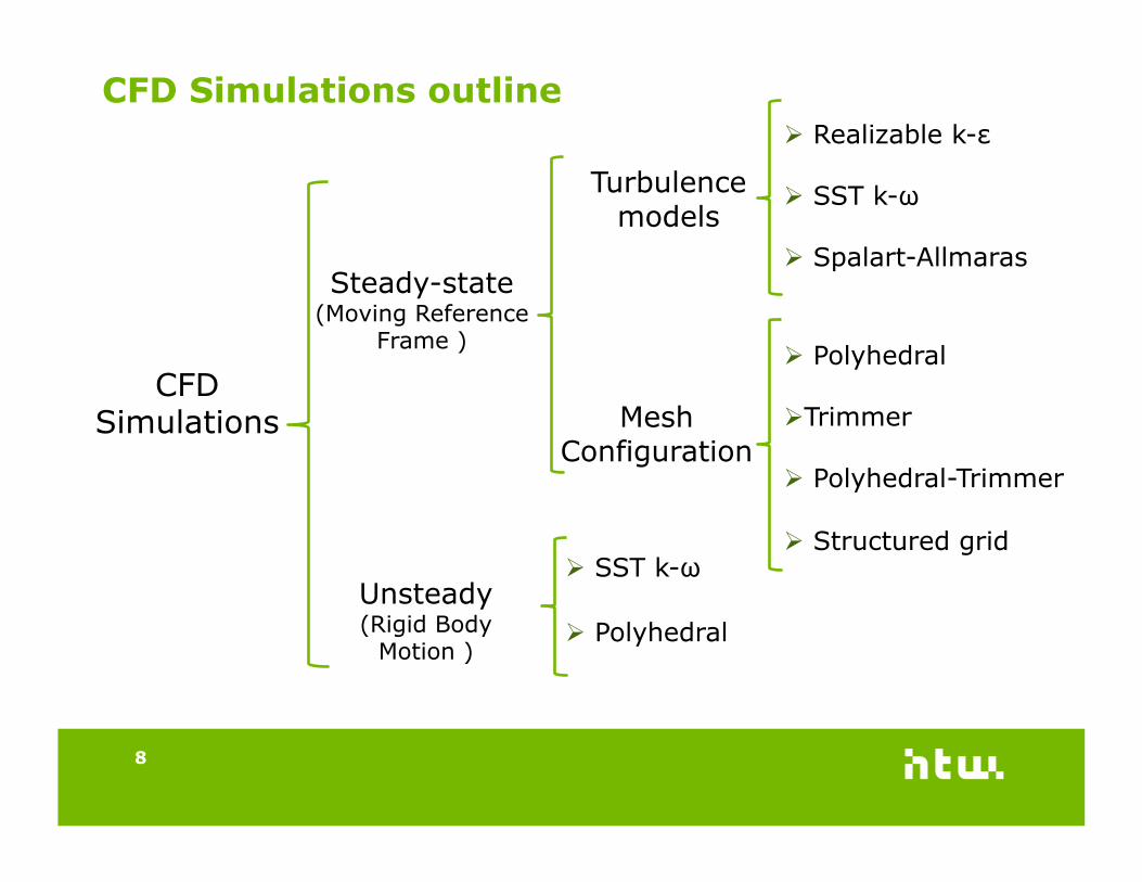
CFD Simulations outline
Turbulence models
Mesh Configuration
Realizable k-ε
SST k-ω
Spalart-Allmaras
Polyhedral
Trimmer
Polyhedral-Trimmer
Structured grid
CFD Simulations
Unsteady (Rigid Body
Motion )
Steady-state (Moving Reference
Frame )
Polyhedral
SST k-ω
8

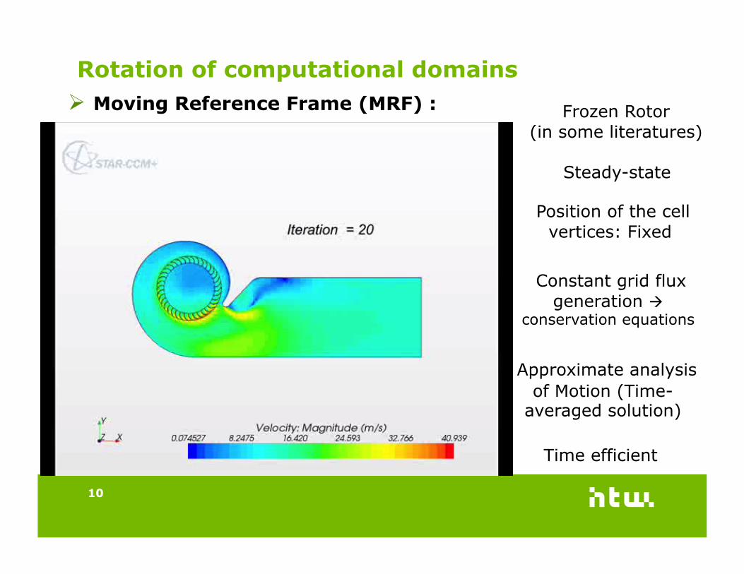
Rotation of computational domains
9
Rigid Body Motion (RBM) : Implicit unsteady
Position of the cell vertices : Moving
Instantaneous local flow behavior Time accurate
solution
Time consuming
Powerful computer is needed
10
Moving Reference Frame (MRF) :
Rotation of computational domains
Frozen Rotor (in some literatures)
Steady-state
Position of the cell vertices: Fixed
Constant grid flux generation
conservation equations
Approximate analysis of Motion (Time-
averaged solution)
Time efficient

Mesh configurations
Conformal Interface Non-Conformal Interface
11
Polyhedral Trimmer Polyhedral-Trimmer
Structured
Mesh generator Star-CCM+ ANSYS ICEM
Number of Cells (in millions)
Total 4.2 6.1 4.0 3.7 Rotor 2.6 4.8 2.7 2.4 Stator 1.6 1.3 1.3 1.3
Interface Mesh Conformal Non-conformal Non-conformal Non-conformal
Mesh generation time 2-4 hours 5-7 days

Mesh configurations comparison
12

Mesh configurations comparison
13
Workstation : CPU : Intel Core i7 (2.8 GHz) RAM : 8 GB

Turbulence models comparison
14

Turbulence models comparison
15
Workstation : CPU : Intel Core i7 (2.8 GHz) RAM : 8 GB

Flow separation in the Nozzle at lower flow rates
Non-uniform inlet flow:
» Dominant flow field generated by Rotor
» Flow attachment to one side & separation from the other side
16

Steady vs. unsteady simulation at 675 m³/h (Overload range)
Static Pressure in Pa
Torque in Nm
Efficiency in %
Exp. 115.8 0.500 41.5
MRF 112.6 0.460 43.9
RBM 114.5 0.470 43.7
Steady (MRF)
Unsteady (RBM)
17

Steady vs. unsteady simulation at 145 m³/h (Throttle range)
Unsteady (RBM)
Steady (MRF)
Static Pressure in Pa
Torque in Nm
Efficiency in %
Exp. 115 0.100 44
MRF 126 0.101 48
RBM 118 0.099 46
18

Conclusions
Unstructured mesh configurations can be used effectively for simulating
sirocco fans.
The best results are achieved by using polyhedral cells.
The best balance between the simulation time and accuracy is achieved
by using Polyhedral cells as well.
Trimmer (as a single mesher) is not suitable for sirocco fan simulation.
SST k-ω turbulence model is the most suitable model for simulating
sirocco fans.
At intermediate and higher flow rates, steady-state MRF approach
provides the same level of accuracy as unsteady RBM approach.
At lower flow rates, flow becomes highly unsteady, and the flow condition
is not suited to steady-state MRF approach.
19

Thank you for your attention!