Embed Size (px)
Citation preview
Paper: ASAT-16-042-PP
16th
International Conference on
AEROSPACE SCIENCES & AVIATION TECHNOLOGY,
ASAT - 16 – May 26 - 28, 2015, E-Mail: [email protected]
Military Technical College, Kobry Elkobbah, Cairo, Egypt
Tel : +(202) 24025292 – 24036138, Fax: +(202) 22621908
Numerical Investigation on the Effect of Using Mixtures of
Natural Gas and Aviation Fuel on Flame Characteristics of Swirl
Gas Turbine Combustor Ahmed I. Farag
*, Tarek M. Belal
†, and Akram E. Zeid
‡
Abstract: The present paper is directed to study aviation fuel combustion compared to that of
natural gas in a gas turbine swirl Combustor. Finite-volume based CFD commercial package
ANSYS Fluent 12 is used for the present investigation. The SST k-ω model is used to
simulate turbulence. The non-premixed combustion model is used to simulate the reacting
flow. Combustion of natural gas is sooty in nature. Thus, soot distribution in the combustor is
investigated numerically using the two step soot model. Simple expressions for the soot
formation and oxidation rates were employed. The radiation heat transfer equation was solved
using the P-1 radiation model. The formation of thermal NO from molecular nitrogen was
modeled and the prompt NO was also included in the computations. CFD modeling is
validated against experimental temperature measurements for a swirl combustor when firing
natural gas as referred to a previous paper. Using the SST-K-ω for predicting gas temperature
distributions satisfy reasonable agreement with the experimental temperature measurements,
except near the combustor upstream and in the vicinity of the combustor axis.
Keywords: Compressed natural gas, Aviation fuel, Gas Turbine Combustor, Temperature
distributions and CFD Modeling, Swirl flame, Turbulence–chemistry interaction, model
Validation.
Nomenclature
A/F Primary air to fuel mass ratio RZ Recirculation Zone
S Swirl Number RFZ Reverse Flow Zone
L Combustor Length r/R Dimensionless Radial Distance
D Combustor Diameter x/D Dimensionless Axial Distance
*Ahmed I. Farag, Dr. Colonel Engineer, Lecturer free, Email: [email protected]
†Tarek M. Belal, Dr. college of engineering, pharos univ., Email: [email protected]
‡ Akram E. Zeid, Dr. College of maritime transportation, Email: akram zaid [email protected]
Paper: ASAT-16-042-PP
1-Introduction:
A gas turbine is one of the most reliable devices for power generation and aircraft
applications. Gas turbine combustors are responsible for the combustion process that provides
energy to the turbine section. Challenges facing the combustor design are related to its wall
cooling, flame stability and emissions control. These features determine the gas turbine
operational range, durability, cost and emissions characteristics [1,2]. The combustion process
within a gas turbine engine is a complex interaction between flow aerodynamics, chemical
kinetics, and air-fuel mixing. Each of these processes plays an essential role in the combustor
design and has been studied extensively over years. Comprehensive previous works regarding
the flow aerodynamics, the combustion process, fuels used in gas turbines are provided.
Natural Gas is a naturally occurring mixture consisting mainly of methane. The average
heating value will depend on the mixtures supplies, and therefore can vary from the typical
values [3]. Natural gas has been increasingly used as a fuel such as in gas turbines for power
generation and in natural gas vehicles (NGVs) as an alternative fuel. However, significant
amounts of pollutant emissions in gas turbine applications, particularly NOx and unburned
methane, can be pointed out as the major drawbacks of its utilization [4]. Aviation fuels are
used for powering aircraft engines where there are two main grades of aviation fuels in use in
aviation field: Jet A and Jet A-1, both are kerosene type fuels [5,6].
Many studies review using CFD analysis in gas turbine combustors used in power generation,
aero-engines and combustion industries [7-11]. New computational methods are developed
for solving problems in different engineering fields. One of these fields is gas turbines where
the challenge is to increase gas turbine efficiency and to reduce pollutant emissions.
Combustion chambers in gas turbines need to be improved for this reason. Therefore, many
experimental and numerical methods are performed to optimize the gas turbine combustion
chamber design.
Pollutant emissions from gas turbines have been of great concern for several decades. NOx
from aircraft engines emits directly to the upper atmosphere layers which contributes to
depletion of ozone layer [12]. New fuels are considered as alternative to petroleum based
fuels. Some other fuels are preferred to mix with petroleum fuels, because its properties are
closer to those of the latter. Studies of the effect of mixtures of Jet-A and other fuels on
emission characteristics of a gas turbine combustion are performed by Mendez et al. Butanol
from 25% to 75% by volume, were mixed with jet-a and used as an alternative fuel. Specific
fuel consumption, turbine inlet temperature, exhaust gas temperature, and emission
characteristics were investigated. NOx and CO emission were lowered for butanol-blends
compared to those with Jet-A [13-18].
All methods of emissions reduction is a “trade-off” between CO and UHC on one side and
NOx on the other side [19]. The majority of NOx emissions are generated in the highest
temperature regions within the combustor taking place in the primary zone before gases
diluted [20]. Technologies have been developed to decrease these pollutant emissions
simultaneously, the key of which is to avoid stoichiometric reactions, to operate at
temperatures sufficient for CO oxidation but does not enhance NOx zone [21, 22].
Flow aerodynamics plays a vital role in design and performance of gas turbine Engines. Good
mixing is essential for high burning rates and minimizing pollutant emissions. Obtaining a
satisfactory temperature distribution in the exhaust is very dependent on mixing [22].
Introducing a swirl flow in gas turbine engine proved a promising way in reducing emissions.
[ 22-22 ]. Different methods that generate swirl are to impart a tangential or azimuthal velocity
component to the flow. The degree of swirl can be characterized by a parameter called the
swirl number (S), which is defined as the ratio of the axial flux of angular momentum to the
Paper: ASAT-16-042-PP
axial flux of axial momentum times the exit radius [22]. When swirl number is increased, a
strong coupling develops between the axial and tangential velocity components. A point is
reached when the adverse pressure gradient along the jet axis cannot be further overcome by
the kinetic energy of the fluid particles in the axial direction, and a reverse flow zone is
formed in the central portion of the jet [27, 28].
Chigier and Chervinsky [29] found that the reverse flow zone is formed beyond a swirl
number ˃ 0.6. Tangirala et al [30] studied the effect of swirl number variations and showed
that increasing the swirl improves mixing and flame stability for swirl numbers up to 1.0.
Further increase in swirl reduced turbulence levels and flame stability. The recommended
swirl number falls in the range of 0.6 up to 1.0. In combustion, the gas axial velocity is higher
compared to the isothermal case due to the gas expansion [23]. Also, the strength of the
recirculation zone is for the reacting case, and the overall length of the recirculation zone is
shorter compared to the non-reacting case [22, 33].
Air Pollutants become a concern, especially NOx due to its contribution to smog, acid rain,
and depletion of ozone layer. The main sources of nitric oxide emissions in combustion are:
1-Oxidation of molecular nitrogen via the thermal NO mechanism 2-Formation of NO via the
prompt mechanism and 3-Oxidation of nitrogen-containing compounds in the fuel via the
fuel-bound NO mechanism. These sources depend on operating conditions and the fuel types
[34].
Kenbar et al [35] reported that increased swirl produced locally higher NOx concentrations
within the central recirculation zone but it did not contribute significantly to overall NOx
emissions. Chen and Driscoll [36] reported that increasing the swirl intensity does not
significantly affect NOx. Schmittel at al [37], using natural gas diffusion flames with found
that NOx emissions decreased significantly with increasing the swirl number. This is due to a
higher recirculated mass flow rate through the recirculation zone which led to decreasing the
residence time within that zone with increasing the swirl number and so NOx is reduced.
Mellor et al [38] measured the temperature and species within a combustor using liquid
propane at an overall equivalence ratio of 0.217. They observed that high NOx concentrations
were found along the centerline in the region thought to be within the recirculation zone.
Claypole, et al [39] studied the influence of swirl levels on the aerodynamics and NOx
emissions using natural gas with 10% excess air. They concluded that the recirculation zone,
despite its long residence time and moderate temperatures, did not contribute to NOx.
One concern to a gas turbine combustor is to minimize CO levels. Significant amount of CO
is produced due to lack of oxygen or due to dissociation of CO2 in fuel-lean combustion, or
due to low combustion temperature in lean-fuel reacting flow cases. Usually, in gas turbine
combustion, CO increases rapidly in the flame zone to a maximum value, followed by a
slower decrease toward the equilibrium concentration. Correa [40] pointed out that carbon
monoxide produced in the flame stabilization zone can survive the flame and must be
oxidized in the turbulent post-flame gas, introducing a much greater dependence on
aerodynamics than is the case for NO, (in lean premixed flames). He also referred that the
reason for CO emissions to increase within the flame stabilization zone because CH species
react much more rapidly than CO with oxidizing radicals. Thus CO cannot be oxidized until
the gas exits the stabilization region and the CH levels drop.
Baulch and Drysdale [41] evaluated the reaction rate of this mechanism and concluded that
this reaction path is important in combustion systems where it acts as the principle source of
CO2 and plays a major role in determining the yield of CO. Bowman [42] cited that for
temperatures below 1000 K, the reaction rate constant (k) is independent of temperature.
Paper: ASAT-16-042-PP
However, at higher temperatures in excess of 1500 K, the rate coefficient k exhibits
significant temperature dependence. Correa referred that the rate of CO oxidation is reduced
by more than two orders of magnitude between flame-like (1800K) and combustor liner-like
(1100-1200K) temperatures. An alternative reaction path that might have significance on CO
oxidation at lower temperatures (1000-1500 K) was suggested by Westenberg and de Ha [43].
Natural gas has been used as an alternative to petroleum fuels to reduce their consumption and
to prolong their life and as potential for reducing exhaust emissions. It has the ability of
reducing exhaust green gas emissions. It is also used for safety handling and secured
operations than that of using petroleum fuels. From previous literature it is clear that
researches about aviation fuel combustion are not enough. Also the shortage in production of
petroleum based fuels is increasing which stimulate the study of alternative fuel and fuel
mixtures. Therefore, the present paper is directed to study the effect of natural gas and jet-A
mixtures on combustion characteristics in aircraft gas turbines.
Different ratios of natural gas (mainly methane) to jet-A aviation fuel are used. The study is
started using natural gas only and then jet-A fuel. Then the study was extended to use 10%
methane up to 75% and then results are compared with the 100 methane. The total air to fuel
ratio in the gas turbine combustor may exceed 100. Air entering the combustor is divided into
two streams, primary air (combustion air) and secondary air (20% of total air). The present
study is concerned about combustion air and the effect of secondary air is not considered
since the combustor used is water cooled. In this study primary air to fuel ratio is about of 40
which results in appropriate flame size for the model combustor.
2-CFD Modeling
This paper is directed to investigate numerically combustion characteristics of aviation and
natural gas fuels in a gas turbine combustor. The present study is started to investigate the
effect of swirl number on the cold flow field in the combustor (Axial velocity distributions
and the RFZ). Then the effect of swirl number on flme sharacteristics in terms of temperature
maps will is investigated using natural gas fuel. Finally the investigation will be extended to
the effect of using mixtures of natural gas and aviation fuels on combustion and emission
characteristics. A test combustor attached wth an air at its upstream end is used. Different air
wirlers are used to study the effect of swirl number on flow field and combustion
characteristics. The swirlers used have same blockage ratio of 0.72 (inner diameter=36 mm
and outer diameter=50 mm) with different vane angles. The swirlers vane angles used are of
30o, 40, 45
o, and 52
o to produce swirl
numbers of 0.5, 0.7, 0.9 and 1.1, respectively since the
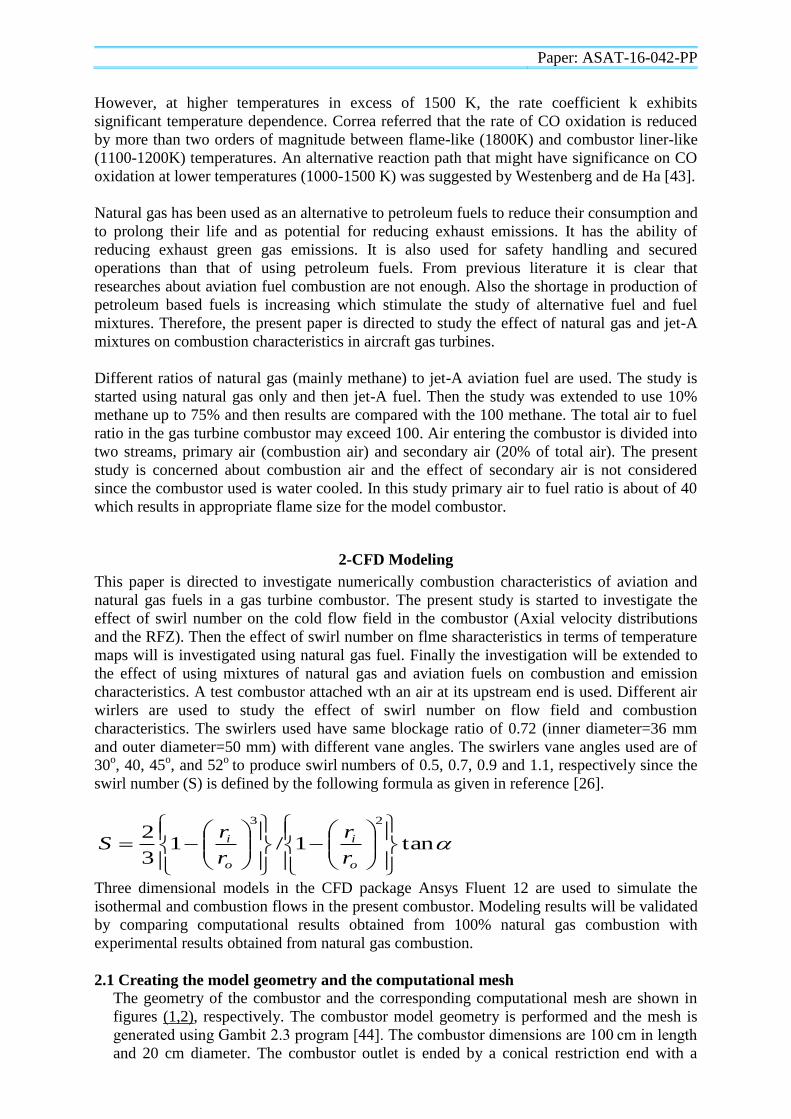
swirl number (S) is defined by the following formula as given in reference [26].
tan1/13
223
o
i
o
i
r
r
r
rS
Three dimensional models in the CFD package Ansys Fluent 12 are used to simulate the
isothermal and combustion flows in the present combustor. Modeling results will be validated
by comparing computational results obtained from 100% natural gas combustion with
experimental results obtained from natural gas combustion.
2.1 Creating the model geometry and the computational mesh The geometry of the combustor and the corresponding computational mesh are shown in
figures (1,2), respectively. The combustor model geometry is performed and the mesh is
generated using Gambit 2.3 program [44]. The combustor dimensions are 100 cm in length
and 20 cm diameter. The combustor outlet is ended by a conical restriction end with a
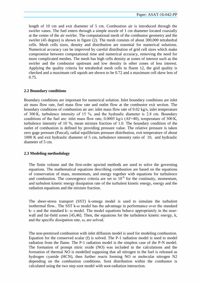
Paper: ASAT-16-042-PP
length of 10 cm and exit diameter of 5 cm. Combustion air is introduced through the
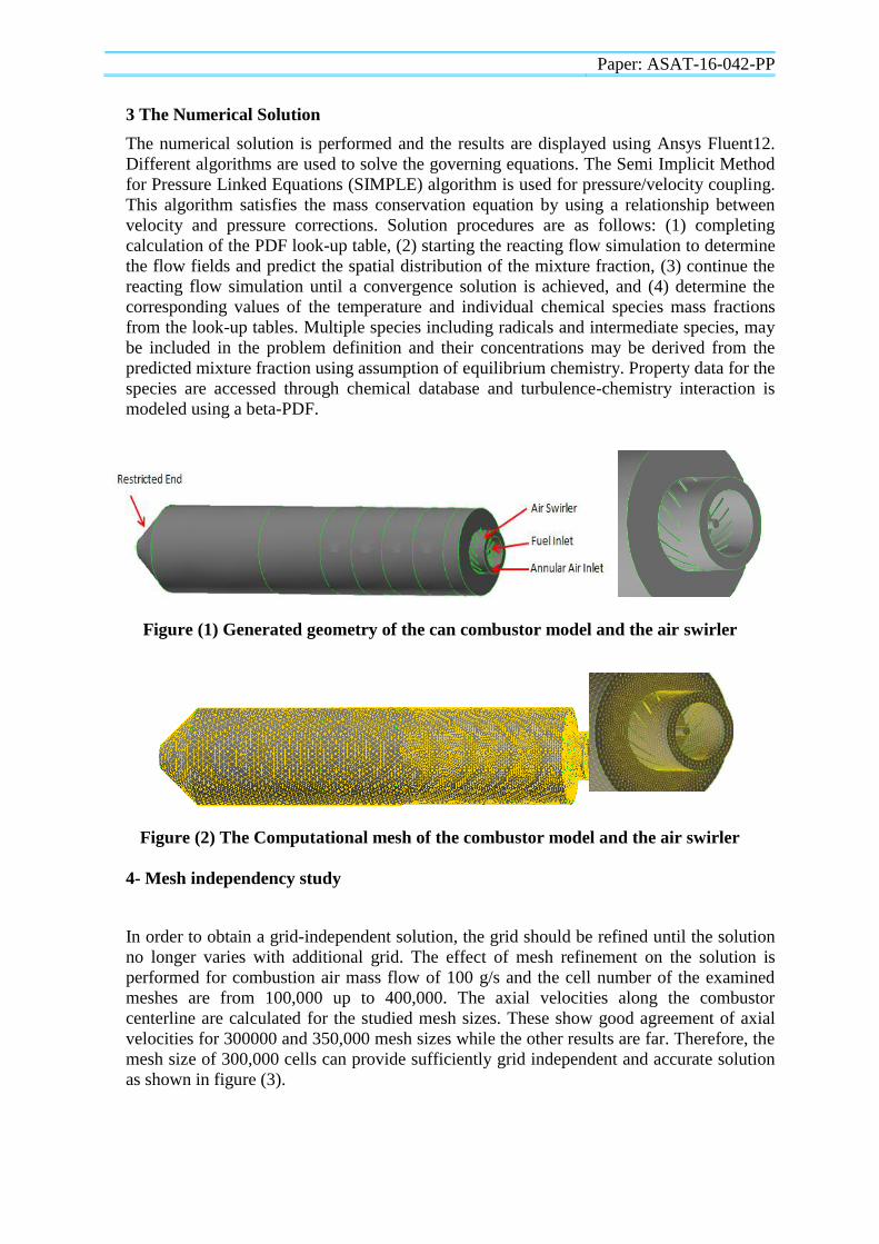
swirler vanes. The fuel enters through a simple nozzle of 1 cm diameter located coaxially
at the center of the air swirler. The computational mesh of the combustor geometry and the
swirler (45 degree) is shown in figure (2). The mesh consists of about 300,000 tetrahedral
cells. Mesh cells sizes, density and distribution are essential for numerical solutions.
Numerical accuracy can be improved by careful distribution of grid cell sizes which make
compromise between computational time and numerical accuracy, removing the need for
more complicated meshes. The mesh has high cells density at zones of interest such as the
swirler and the combustor upstream and low density in other zones of less interest.
Applying the quality criteria for tetrahedral mesh cells in fluent 12, the grid quality is
checked and a maximum cell squish are shown to be 0.72 and a maximum cell skew less of
0.75.
2.2 Boundary conditions
Boundary conditions are important for numerical solution. Inlet boundary conditions are inlet
air mass flow rate, fuel mass flow rate and outlet flow at the combustor exit section. The
boundary conditions of combustion air are: inlet mass flow rate of 0.02 kg/s, inlet temperature
of 300 K, turbulence intensity of 15 %, and the hydraulic diameter is 2.8 cm. Boundary
conditions of the fuel are: inlet mass flow rate, 0.0005 kg/s (AF=40), temperature of 300 K,
turbulence intensity of 10 %, mean mixture fraction of 1.0. The boundary condition of the
outlet of combustion is defined by providing pressure value. The relative pressure is taken
zero gage pressure (Pascal), radial equilibrium pressure distribution, exit temperature of about
1000 K and exit hydraulic diameter of 5 cm, turbulence intensity ratio of 10, and hydraulic
diameter of 5 cm.
2.3 Modeling methodology
The finite volume and the first-order upwind methods are used to solve the governing
equations. The mathematical equations describing combustion are based on the equations
of conservation of mass, momentum, and energy together with equations for turbulence
and combustion. The convergence criteria are set to 10-6
for the continuity, momentum,
and turbulent kinetic energy dissipation rate of the turbulent kinetic energy, energy and the
radiation equations and the mixture fraction.
The sheer-stress transport (SST) k-omega model is used to simulate the turbulent
isothermal flow.. The SST k-ω model has the advantage in performance over the standard
k- ε and the standard k- ω model. The model equations behave appropriately in the near-
wall and far-field zones [45,46]. Then, the equations for the turbulence kinetic energy, k,
and the specific dissipation rate, ω, are solved.
The non-premixed combustion with inlet diffusion model is used for modeling combustion.
Equation for the conserved scalar (f) is solved. The P-1 radiation model is used to model
radiation from the flame. The P-1 radiation model is the simplest case of the P-N model.
The formation of prompt nitric oxide (NO) was included in the calculations and the
formation of thermal NO is modelled supposing that all nitrogen in the fuel is released as
hydrogen cyanide (HCN), then further reacts forming NO or molecular nitrogen N2
depending on the combustion conditions. Soot distribution within the combustor is
calculated using the two step soot model with soot-radiation interaction.
Paper: ASAT-16-042-PP
3 The Numerical Solution
The numerical solution is performed and the results are displayed using Ansys Fluent12.
Different algorithms are used to solve the governing equations. The Semi Implicit Method
for Pressure Linked Equations (SIMPLE) algorithm is used for pressure/velocity coupling.
This algorithm satisfies the mass conservation equation by using a relationship between
velocity and pressure corrections. Solution procedures are as follows: (1) completing
calculation of the PDF look-up table, (2) starting the reacting flow simulation to determine
the flow fields and predict the spatial distribution of the mixture fraction, (3) continue the
reacting flow simulation until a convergence solution is achieved, and (4) determine the
corresponding values of the temperature and individual chemical species mass fractions
from the look-up tables. Multiple species including radicals and intermediate species, may
be included in the problem definition and their concentrations may be derived from the
predicted mixture fraction using assumption of equilibrium chemistry. Property data for the
species are accessed through chemical database and turbulence-chemistry interaction is
modeled using a beta-PDF.
Figure (1) Generated geometry of the can combustor model and the air swirler
Figure (2) The Computational mesh of the combustor model and the air swirler
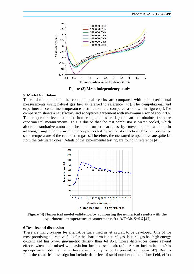
4- Mesh independency study
In order to obtain a grid-independent solution, the grid should be refined until the solution
no longer varies with additional grid. The effect of mesh refinement on the solution is
performed for combustion air mass flow of 100 g/s and the cell number of the examined
meshes are from 100,000 up to 400,000. The axial velocities along the combustor
centerline are calculated for the studied mesh sizes. These show good agreement of axial
velocities for 300000 and 350,000 mesh sizes while the other results are far. Therefore, the
mesh size of 300,000 cells can provide sufficiently grid independent and accurate solution
as shown in figure (3).
Paper: ASAT-16-042-PP
Figure (3) Mesh independency study
5. Model Validation
To validate the model, the computational results are compared with the experimental
measurements using natural gas fuel as referred to reference [47]. The computational and
experimental centerline temperature distributions are compared as shown in figure (4).The
comparison shows a satisfactory and acceptable agreement with maximum error of about 8%.
The temperature levels obtained from computations are higher than that obtained from the
experimental measurements. This is due to that the test combustor is water cooled, which
absorbs quantitative amounts of heat, and further heat is lost by convection and radiation. In
addition, using a bare wire thermocouple cooled by water, its junction does not obtain the
same temperature of the combustion gases. Therefore, the measured temperatures are quite far
from the calculated ones. Details of the experimental test rig are found in reference [47].
Figure (4) Numerical model validation by comparing the numerical results with the
experimental temperature measurements for A/F=30, S=0.5 [47]
6-Results and discussion
There are many reasons for alternative fuels used in jet aircraft to be developed. One of the
most promising alternative fuels for the short term is natural gas. Natural gas has high energy
content and has lower gravimetric density than Jet A-1. These differences cause several
effects when it is mixed with aviation fuel to use in aircrafts. Air to fuel ratio of 40 is
appropriate to obtain suitable flame size to study using the present combustor [47]. Results
from the numerical investigation include the effect of swirl number on cold flow field, effect
Paper: ASAT-16-042-PP
of swirl number on temperature maps of natural gas flame, and effect on temperature maps
and emissions using different mixtures of natural gas and aviation fuels. Natural gas quantities
included in the investigation are: 10%, 25%, 50%, 75%, and 100%.
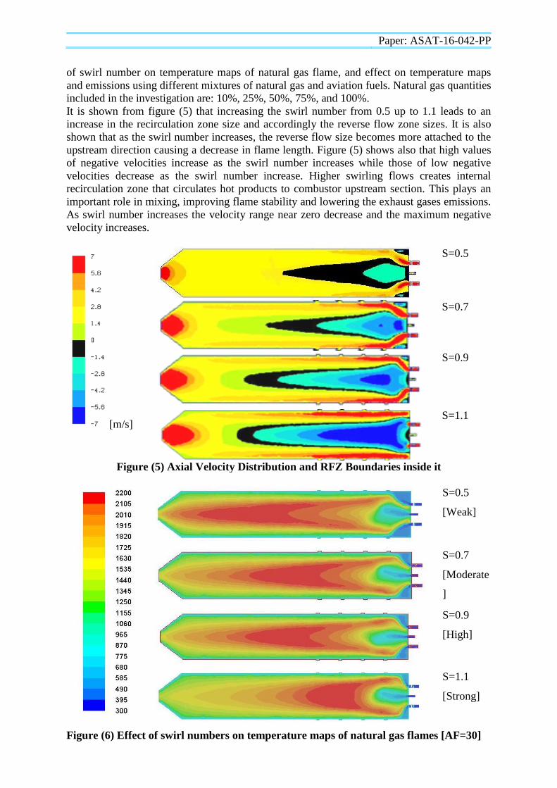
It is shown from figure (5) that increasing the swirl number from 0.5 up to 1.1 leads to an
increase in the recirculation zone size and accordingly the reverse flow zone sizes. It is also
shown that as the swirl number increases, the reverse flow size becomes more attached to the
upstream direction causing a decrease in flame length. Figure (5) shows also that high values
of negative velocities increase as the swirl number increases while those of low negative
velocities decrease as the swirl number increase. Higher swirling flows creates internal
recirculation zone that circulates hot products to combustor upstream section. This plays an
important role in mixing, improving flame stability and lowering the exhaust gases emissions.
As swirl number increases the velocity range near zero decrease and the maximum negative
velocity increases.
[m/s]
S=0.5
S=0.7
S=0.9
S=1.1
Figure (5) Axial Velocity Distribution and RFZ Boundaries inside it
S=0.5
[Weak]
S=0.7
[Moderate
]
S=0.9
[High]
S=1.1
[Strong]
Figure (6) Effect of swirl numbers on temperature maps of natural gas flames [AF=30]
Paper: ASAT-16-042-PP
From figure (6), it is shown from the temperature maps that as the swirl number increase, then
the temperature levels are decreased and move to the upstream direction. Also the sizes of the
high temperature regions are decreased and move to the upstream direction. This indicates
that the flame length is decreased as the swirl number increases and also the high
temperatures in the flame move near the swirler exit and the flame becomes wider in
diameter. So, from the numerical investigation, there is a remarkable effect when using
different air swirl numbers on temperature maps as shown n figure put below.
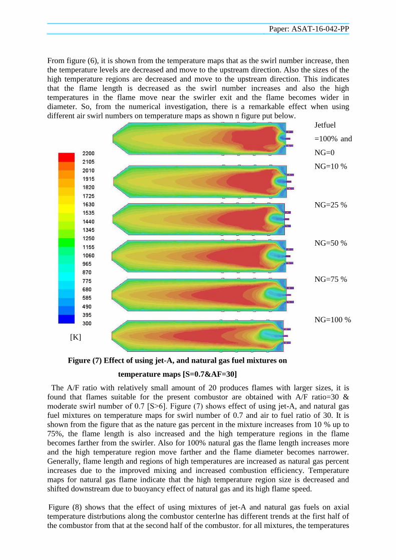
[K]
Jetfuel
=100% and
NG=0
NG=10 %
NG=25 %
NG=50 %
NG=75 %
NG=100 %
Figure (7) Effect of using jet-A, and natural gas fuel mixtures on
temperature maps [S=0.7&AF=30]
The A/F ratio with relatively small amount of 20 produces flames with larger sizes, it is
found that flames suitable for the present combustor are obtained with A/F ratio=30 &
moderate swirl number of 0.7 [S˃6]. Figure (7) shows effect of using jet-A, and natural gas
fuel mixtures on temperature maps for swirl number of 0.7 and air to fuel ratio of 30. It is
shown from the figure that as the nature gas percent in the mixture increases from 10 % up to
75%, the flame length is also increased and the high temperature regions in the flame
becomes farther from the swirler. Also for 100% natural gas the flame length increases more
and the high temperature region move farther and the flame diameter becomes narrower.
Generally, flame length and regions of high temperatures are increased as natural gas percent
increases due to the improved mixing and increased combustion efficiency. Temperature
maps for natural gas flame indicate that the high temperature region size is decreased and
shifted downstream due to buoyancy effect of natural gas and its high flame speed.
Figure (8) shows that the effect of using mixtures of jet-A and natural gas fuels on axial
temperature distrbutions along the combustor centerlne has different trends at the first half of
the combustor from that at the second half of the combustor. for all mixtures, the temperatures
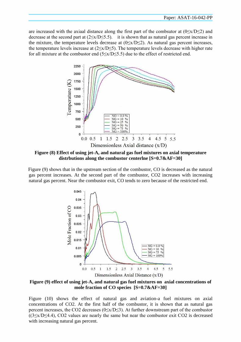
Paper: ASAT-16-042-PP
are increased with the axiaal distance along the first part of the combsutor at (0≤x/D≤2) and
decrease at the second part at (2≤x/D≤5.5). it is shown that as natural gas percent increase in
the mixture, the temperature levels decrease at (0≤x/D≤2). As natural gas percent increases,
the temperature levels increase at (2≤x/D≤5). The temperature levels decrease with higher rate
for all mixture at the combustor end (5≤x/D≤5.5) due to the effect of restricted end.
Figure (8) Effect of using jet-A, and natural gas fuel mixtures on axial temperature
distrbutions along the combustor centerlne [S=0.7&AF=30]
Figure (9) shows that in the upstream section of the combustor, CO is decreased as the natural
gas percent increases. At the second part of the combustor, CO2 increases with increasing
natural gas percent. Near the combustor exit, CO tends to zero because of the restricted end.
Figure (9) effect of using jet-A, and natural gas fuel mixtures on axial concentrations of
mole fraction of CO species [S=0.7&AF=30]
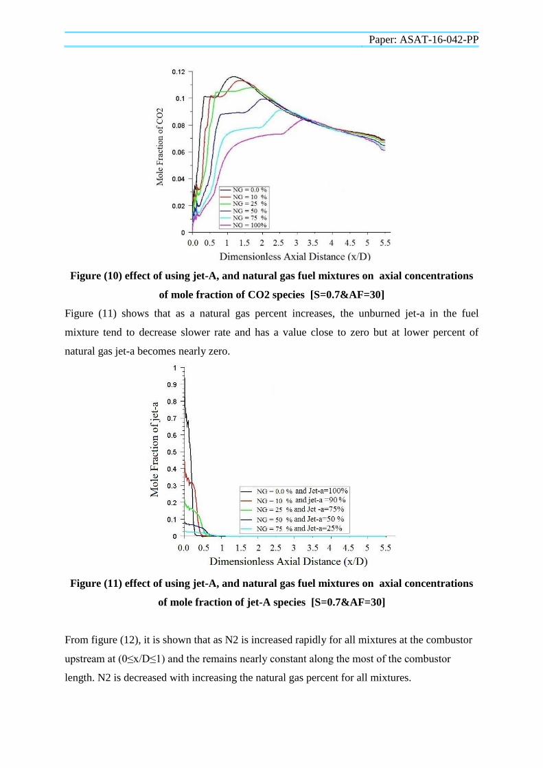
Figure (10) shows the effect of natural gas and aviation-a fuel mixtures on axial
concentrations of CO2. At the first half of the combustor, it is shown that as natural gas
percent increases, the CO2 decreases (0≤x/D≤3). At further downstream part of the combustor
((3≤x/D≤4.4), CO2 values are nearly the same but near the combustor exit CO2 is decreased
with increasing natural gas percent.
Paper: ASAT-16-042-PP
Figure (10) effect of using jet-A, and natural gas fuel mixtures on axial concentrations
of mole fraction of CO2 species [S=0.7&AF=30]
Figure (11) shows that as a natural gas percent increases, the unburned jet-a in the fuel
mixture tend to decrease slower rate and has a value close to zero but at lower percent of
natural gas jet-a becomes nearly zero.
Figure (11) effect of using jet-A, and natural gas fuel mixtures on axial concentrations
of mole fraction of jet-A species [S=0.7&AF=30]
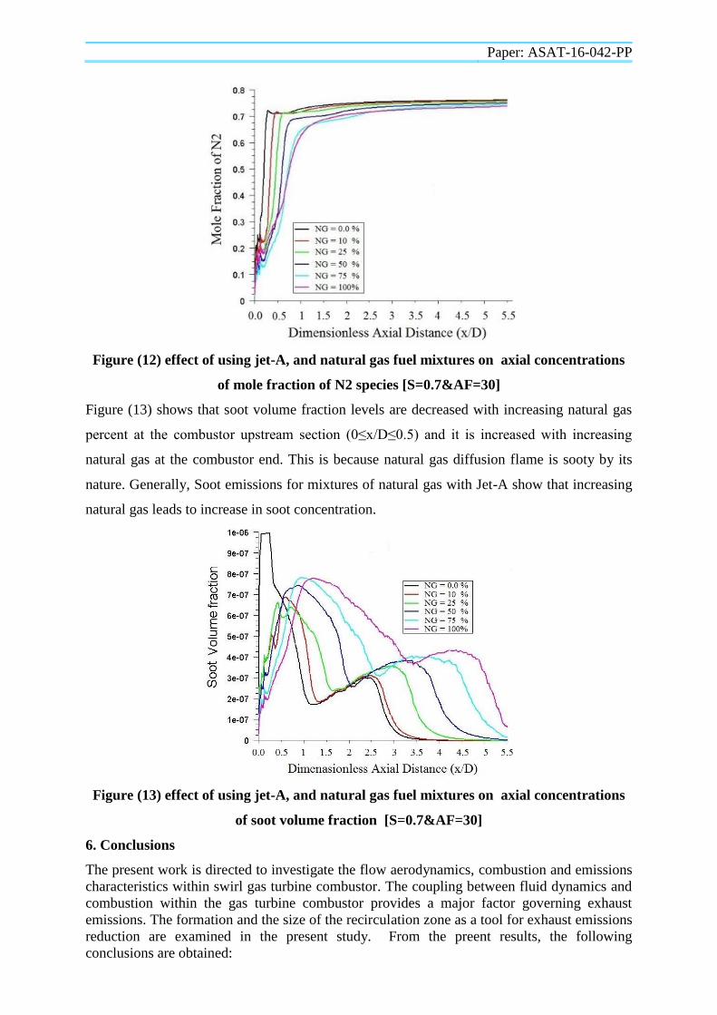
From figure (12), it is shown that as N2 is increased rapidly for all mixtures at the combustor
upstream at (0≤x/D≤1) and the remains nearly constant along the most of the combustor
length. N2 is decreased with increasing the natural gas percent for all mixtures.
Paper: ASAT-16-042-PP
Figure (12) effect of using jet-A, and natural gas fuel mixtures on axial concentrations
of mole fraction of N2 species [S=0.7&AF=30]
Figure (13) shows that soot volume fraction levels are decreased with increasing natural gas
percent at the combustor upstream section (0≤x/D≤0.5) and it is increased with increasing
natural gas at the combustor end. This is because natural gas diffusion flame is sooty by its
nature. Generally, Soot emissions for mixtures of natural gas with Jet-A show that increasing
natural gas leads to increase in soot concentration.
Figure (13) effect of using jet-A, and natural gas fuel mixtures on axial concentrations
of soot volume fraction [S=0.7&AF=30]
6. Conclusions
The present work is directed to investigate the flow aerodynamics, combustion and emissions
characteristics within swirl gas turbine combustor. The coupling between fluid dynamics and
combustion within the gas turbine combustor provides a major factor governing exhaust
emissions. The formation and the size of the recirculation zone as a tool for exhaust emissions
reduction are examined in the present study. From the preent results, the following
conclusions are obtained:
Paper: ASAT-16-042-PP
1-In non-reacting flow, the central recirculation zone has larger size compared to corner
recirculation zone as a result of highly swirling flow and vice-verse for low swirl flow.
2-High turbulence levels are achieved within the combustor dome due to the swirling effects.
3- The high levels of turbulence and the resulting good mixing of fuel with air explain the
success of the air swirler to produce uniform temperature distribution within the gas turbine
combustor and low exhaust emissions.
4-The recirculation zone tends to be longer and wider with increasing the swirl number
especially at upstream section.
5-The swirl number may not be the correct parameter to characterize the properties of the
recirculation zone while sufficient swirl is needed to recirculate the flow.
6- The flow aerodynamics can play a significant role in either decreasing exhaust species
concentrations based on their location and strength.
7-Maximum UHC are found near the combustor upstream before that of the CO. Maximum
N2 concentrations are found farther downstream of CO and UHC maximums.
References
[1] Guenther C. Krieger, Andre P. V. de Campos, Fernando L. Sacomano Filho, Rafael C. de
Souza, “A swirler stabilized combustion chamber for a micro-gas turbine fuelled with
natural gas”, J. Braz. Soc. Mech. Sci. & Eng. vol.34 no.4 Rio de Janeiro Oct./Dec. (2012)
[2] P. Sravan Kumar and P. Punna Rao, “Design and Analysis of Gas Turbine Combustion
Chamber”, International Journal Of Computational Engineering Research (ijcer) Vol. 03
Issue 12 (December 2013) 36:40.
[3] Ahmed I. Farag,“A study of secondary air effect on natural gas combustion characteristics”
Ph. D. thesis, college of engineering, port said university, (2012).
[4] Firoj, H. P., Nikul, K. P., Mihir, V. T., “ Numerical Investigation of the Combustion of
Methane Air Mixture in Gas Turbine Can-Type Combustion Chamber”, International
Journal of Scientific & Engineering Research, Volume 3, Issue 10, (2012)
[5] Gupta, A. K., Lilley, D. G., and Syred, N., Swirl flows, Abacus Press, 1984.
[6] William Allan, Marc La Violette and Pierre Poitras, “Emissions From a Gas Turbine Sector
Rig Operated With Synthetic Aviation and Biodiesel Fuel”, Journal of Engineering for Gas
Turbines and Power, Volume 133, Issue 11, (May, 2011).
[7] Eldrainy, Y.A., Saqr, K.M., Aly, H.S., Nazri Mohd J.M., “CFD insight of the flow
dynamics in a novel swirler for gas turbine combustors”, International Communications in
Heat and Mass Transfer 36, 936 – 94, (2009).
[8] Mark, D.T., Philip, J.S., Syed, K. J., and Eoghan, B., “CFD Simulation of the Flow Within
and Downstream of a High Swirl Lean Premixed Gas Turbine Combustor”, Proceedings of
ASME Turbo Expo 2004 Power for Land, Sea, and Air, June 14–17, (2004), Vienna,
Austria, GT2004-53112
[9] Thiago, K.A., Carlo E.F., Karolline R., Da Silva, L.F., and Luis Enrique A. H., “CFD
analysis of an inducstrial gas turbine combustion chamber”, 13th
Brazilian Congress of
Thermal Sciences and Engineering December 05-10, 2010, Uberlandia, MG, Brazil
[10] Shaik, M.H., Sudheer, P.K., Vijaya, K.R., “CFD analysis of combustion and emissions to
study the effect of compression ratio and biogas substitution in a diesel engine with
experimental verification”, International Journal of Engineering Science and Technology
(IJEST).
[11] ABDALLAHABOU-TAOUK, “CFD Modeling of Combustion in Flexi-Fuel Burners at
Gas Turbine Conditions”, Division of Fluid Dynamics, Department of Applied Mechanics
CHALMERS UNIVERSITY OF TECHNOLOGY, Goteborg, Sweden, (2011).
[12] Mongia, H.C., "A Fourth Generation Propulsion Combustor Technology for Low
Emissions," AIAA International Air and Space Symposium and Exposition: The Next 100
Years , 2003.
Paper: ASAT-16-042-PP
[13] Mongia, H.C., "A Fourth Generation Propulsion Combustor Technology for Low
Emissions," AIAA International Air and Space Symposium and Exposition: The Next 100
Years , 2003.
[14] Nima Mirzamohammad, Omid Razbani, and Mohsen Assadi, “Review of theoretical and
experimental studies implemented on (CHP) Micro turbine using natural gas and biogas
fuels”, Third International Conference on Applied Energy - 16-18 May 2011 - Perugia, Italy
[15] Naitik H. Gor and Milan J. Pandya, “CFD Analysis of Swirl Can Combustion Chamber- A
Review”, IJIRST-International Journal for Innovative Research in science7technology,
Volume 1, issue 6 1 November, 2014.
[16] Fagner Luis Goular Dias, Marco Antonio Rosa do Nascimento, Lucilene de Oliveira
Rodrigues, “Reference Area Investigation in a Gas Turbine Combustion Chamber Using
CFD”, Journal of Mechanical Engineering and Automation 2014, 4(2): 73-82 DOI:
10.5923/j.jmea.20140402.04
[17] Dong-Sik Han, Gyu-Bo Kim, Han-Suk Kim, and Chung-Hwan Jeon, “Experimental study
of NOx correlation for fuel staged combustion using lab-scale gas turbine combustor at high
pressure”, Experimental thermal and fluid science 58-2014:62-69
[18] Mendez, C.J., Parthasarathy, R.N. and Gollahalli, S.R., “Performance and emission
characteristics of butanol/Jet A blends in a gas turbine engine”, Applied Energy, Volume
118 (c ):pages 135-140, 2014.
[19] Lefebvre, A. H., “Pollution Control in Continuous Combustion Engines", Proceedings of
the Combustion Institute, Vol. 15, 1975, pp. 1169-1180.
[20] Stouffer, S. D., Ballal, D. R., Zelina, J., Shouse, D. T., Hancock, R. D., and Mongia, H. C.,
"Development and Combustion Performance of a High-Pressure WSR and TAPS
Combustor," AIAA Paper 2005-1416, January 2005
[21] Tacina, R.R., "Combustor Technology for Future Aircraft," AIAA Paper1990-2400, July
1990.
[22] Penner, J. E., Lister, D. H., Griggs, D. J., Dokken, D. J., and McFarland, M., Aviation and
the global atmosphere , Cambridge University Press, Cambridge, United Kingdom, 1999.
[23] Lefebvre, A. H., Gas Turbine Combustion, 2ed., Taylor and Francis, Philadelphia, PA,
1998.
[24] Syred, N. and Beér, J. M., “Combustion in Swirling Flows: A Review," Combustion and
Flame , Vol. 23, 1974, pp. 143-201.
[25] Sloan, D. G., Smith, P. J., and Smoot, L. D., "Modeling of Swirl in Turbulent Flow
Systems," Progress in Energy and Combustion Science, Vol. 12, 1996, pp. 163-250.
[26] Beer, J.M. and Chigier N., “Combustion Aerodynamics”, Applied Science Publishers LTD,
London , 1972.
[27] Lucca-Negro, O. and O'Doherty, T., “Vortex Breakdown: A Review," Progress in
Energy and Combustion Science , Vol. 27, 2001, pp. 431-481.
[28] Chigier, N. and Beér, J. M., “The Flow Region Near the Nozzle in Double Concentric Jets,"
Journal of Basic Engineering, Vol. 86, No. 4, 1964, pp. 797-804.
[29] Chigier, N. and Chervinsky, A., "Experimental Investigation of Swirling Vortex Motion in
Jets," Journal of Applied Mechanics, Vol. 34, 1967, pp. 443-451.
[30] Tangirala V., Chen, R.H., and Driscoll, J.F., “Effect of Heat Release and Swirl on the
Recirculation within Swirl-Stabilized Flames," Combustion Science and Technology, Vol.
51, 1987, pp. 75-95.
[31] Bulzan, D. L., "Structure of a Swirl-Stabilized Combusting Spray," Journal of Propulsion
and Power, Vol. 11, No. 6, 1995, pp. 1093-1102.
[32] Bornstein, J. and Escudier, M. P., "LDA Measurements within a Vortex-Breakdown
Bubble," International Symposium on Applications of Laser-Doppler Anemometry to Fluid
Mechanics , 1982, pp. 1-11.
[33] Vu, B. T. and Gouldin, F. C., “Flow Measurements in a Model Swirl Combustor," AIAA
Journal, Vol. 20, No. 5, 1982, pp. 642-651.
Paper: ASAT-16-042-PP
[34] Bowman, C. T., "Kinetics of Pollutant Formation and Destruction in Combustion," ogress
in Energy and Combustion Science, Vol. 1, 1975, pp. 33-45.
[35] Kenbar, A. M. A., Beltagui, S. A., Ralston, T., and MacCallum, N. R. L., "Measurement
and Modeling of NOx Formation in a Gas Fired Furnace," Combustion Science and
Technology , Vol. 93, 1993, pp. 173-192.
[36] Chen, R.-H. and Driscoll, J. F., "Nitric Oxide Levels of Jet Diffusion Flames: Effects of
Coaxial Air and Other Mixing Parameters," Proceedings of the Combustion Institute , Vol.
23, 1990, pp. 281-288.
[37] Schmittel, P., Günther, B., Lenze, B., Leuckel, W., and Bockhorn, H., "Turbulent Swirling
Flames: Experimental Investigation of the Flow Field and Formation of Nitrogen Oxide,"
Proceedings of the Combustion Institute, Vol. 28, 2000, pp. 303309.
[38] Mellor, A.M., Anderson, R.D., Altenkirch, R. A., and Tuttle, J. H., "Emissions from and
within an Allison J-33 Combustor," Combustion Science and Technology, Vol. 6, 1972, pp.
169-176.
[39] Claypole, T. C. and Syred, N., “The Effect of Swirl Burner Aerodynamics on NOx
Formation," Proceedings of the Combustion Institute, Vol. 18, 1981, pp. 81-89.
[40] Correa, S. M., "Carbon Monoxide Emissions in Lean Premixed Combustion,"
Journal of Propulsion and Power. Vol.8, No. 6, 1992, pp. 1144-1151.
[41] Baulch, D. L. and Drysdale, D. D., "An Evaluation of the Rate Data for the Reaction + H,
CO + OH --> CO " Combustion and Flame, Vol. 23, 1974, pp. 215-225.
[42] Bowman, C.T. "Chemistry of Gaseous Pollutant Formation and Destruction", Fossil Fuel
Combustion , Wiley & Sons, New York, 1991, pp. 215-260.
[43] Westenberg, A.A. and deHaas, N., "Steady State Intermediate Concentrations and Rate
Constants HO Results," Journal of Physical Chemistry, Vol. 76, No. 11, 1972, pp. 1586-
1593.
[44] GAMBIT Program User Guide, September (2006)
[45] Tobias Knopp, Bernhard Eisfeld and Javier Bartolome Calvo, 2009, “A new extension for
k-ω turbulence models to account for wall roughness”, International Journal of Heat and
Fluid Flow 30, pp. 54–65
[46] Jonas Bredberg, Shia-HuiPeng, Lars Davidson, 2002, “An improved k-ω turbulence model
applied to recirculating flows”, International Journal of Heat and Fluid Flow, 23, pp.731–
743
[47] Akram Zaid and Ahmed Farag “Effect of Secondary Air Configuration in Gas Turbine
Combustor Firing Natural Gas”, Proceedings of ASME 2014 International Mechanical
Engineering Congress & Exposition IMECE2014, Nov. 14-20, 2014, Montreal, Canada.