Embed Size (px)
Citation preview
15 Advances in Railway Engineering, An International Journal Vol.3/ No.1/ Winter and Spring 2015
Numerical Investigation on Effects of Deep Excavations’ Posi-tion on Existing Metro Tunnels in Urban Areas
H. Abbasi*1; H. Katebi2, M. Hajialilue Bonab3
1M.Sc. in Geotechnical Civil Engineering, University of Tabriz, Tabriz, Iran 2Associated Professor, Department of Civil Engineering, University of Tabriz, Tabriz, Iran,
[email protected] Professor, Department of Civil Engineering, University of Tabriz, Tabriz, Iran
Received: 21.02.2015 Accepted: 05.10.2015
Abstract:Nowadays deep excavations are needed for construction of foundation of high rise buildings, providing space for parking and etc. In some cases deep excavations may be constructed in the vicinity of the subway tunnels and causes unpredicted extra displacements and internal forces in tunnel lining of tunnels which were not designed for them and consequently affect serviceability of tunnel. Therefore in order to avoid structural damages, comprehensive studies should be carried out when the excavation is located in adjacent of tunnel and necessary precautions should be ad-opted. In this paper 2D FDM software FLAC 2D was used for modeling and investigating the effects of excavations on existing tunnels in sand layer. In this analysis it is assumed that the cross section of tunnel is circular and tunnel exists before deep excavation and also stress relaxation in the soil body around tunnel was taken into account before installation of tunnel lining. In this study different locations of excavation with respect to the tunnel were taken into account and effects of excavation on induced displacements and changes of internal forces of tunnel lining have been studied. Diaphragm wall is used for retaining of excavation and in the analyses Mohr- Coulomb constitutive model is used for soil body. The results of 2D numerical analyses show that when tunnel is located in the outside of the excava-tion, because of the shielding effect of the diaphragm wall, excavation has less effect on tunnel in comparison with the tunnel which is located below the excavation.
Keywords: Deep Excavation, Tunnel, Numerical Modeling, Finite Difference Method.
* Corresponding Author
16Advances in Railway Engineering, An International Journal Vol.3/ No.1/ Winter and Spring 2015
1. IntroductionDeep excavation is an important issue in geotechnical civil engineering, for example, in the construction of foundation or basement of a high rise building, subways or mass rapid transit systems, etc. It is inevitable to use deep excavation. Economic development and urbaniza-tion make excavations go deeper and larger and some-times they are carried out in difficult soils. These con-ditions usually aren’t discussed in general engineering courses and require advanced analysis such as numerical methods (Ou, 2006).In order to investigate the effects of deep excavations on existing tunnels, many researches have been performed. In some cases researchers have compared field monitoring results with numerical analy-sis results and some others only have carried out numeri-cal simulations.Sharma et al. (2001) have investigated a deep and large excavation in the vicinity of twin MRT tunnels in Singapore using CRISP finite element soft-ware. Also a monitoring system was used for monitoring displacement of tunnels. Results showed that in general, computed displacements are larger than measured values but trends are quite similar. Dolezalova (2001) carried out a research to investigate effects of deep excavation for an office block on the underlying tunnel complex using 2D finite element software CRISP. It was reported that deep excavations have not considerable effect on some tunnel but in some cases decrease of cracking resistance and watertightness in tunnel lining was predicted. Also field measurements was carried out during construction of deep excavation and a good agreement was reported between results of numerical analysis and filed monitor-ing results. Chang et al. (2001) have studied the response of Taipei Rapid Transit System (TRTS) tunnel to adjacent excavation. In the study, it is reported that a section of tunnel in the Panchiao Line was damaged as a result of adjacent excavation. Also, Cracks had appeared in rein-forced concrete segments, the concrete slab on the invert was displaced and detached from the segment. Hu et al. (2003) have presented the design and construction of a deep excavation that was located above and beside the Shanghai Metro tunnels. The paper has discussed some controlling measures for soil and tunnel deformation. The measures included concrete diaphragm wall, pumping consolidation, soil- cement mix pile system and rational excavation procedures.
Karki (2006) has carried out parametric study on the effects of deep excavation on circular tunnels in fine-grained soils using 2D finite element software Plaxis based on Tan Tock Seng Hospital (TTSH) excavation project in Singapore. The excavation was close to MRT twin tunnels. In this study the effect of Young’s modu-lus and undrained shear strength of soil and also stiff-ness of diaphragm wall and tunnel lining as parameters of displacements and internal forces of tunnel was inves-tigated. Zheng and Wei (2008) have carried out numerical analyses on influence of pit excavation on existing tun-nel using 2D finite element software ABAQUS. Modi-fied cam-clay model was used for modeling silty clay soil. Result showed that for tunnels located outside the wall, it experiences more slight distortion during exca-vation. Chen et al. (2011) have carried out a numerical study on the movement of existing tunnel due to deep excavation in Shanghai. In the study, 2D finite element software, ABAQUS, is used to simulate the behavior of soft clay with considering nonlinearity of soil. The in-fluence of some factor, including the excavation proce-dure and installation of resistance piles are investigated. Also, the results of numerical analysis are compared with the results of field measurements. As a result of study, constructing of small pits close to the tunnel can reduce the influence of large pit excavation. Huang et al. (2011) have carried out a parametric study on the influence of deep excavation on nearby existing tunnels in soft soil of Shanghai using 3D finite element software Plaxis-GiD. Results revealed that the influence of excavation on the underlying tunnel is significant in a distance which is about five times the excavation width measured along the tunnel axis. Ding et al. (2012) studied the affection of foundation pit excavation on metro tunnel using 3D finite element analysis software MIDAS\GTS. In this research induced displacements and internal force of tunnel lining due to deep excavation was investigated and reported that effect of excavation on tunnel is not considerable when distance between excavation and tunnel in more than 4 times of tunnel diameter.
2. Characterization of deformation of the tunnel liningDeep excavations adjacent to existing structures such as tunnels, raft foundations or pile foundations, are highly
17 Advances in Railway Engineering, An International Journal Vol.3/ No.1/ Winter and Spring 2015
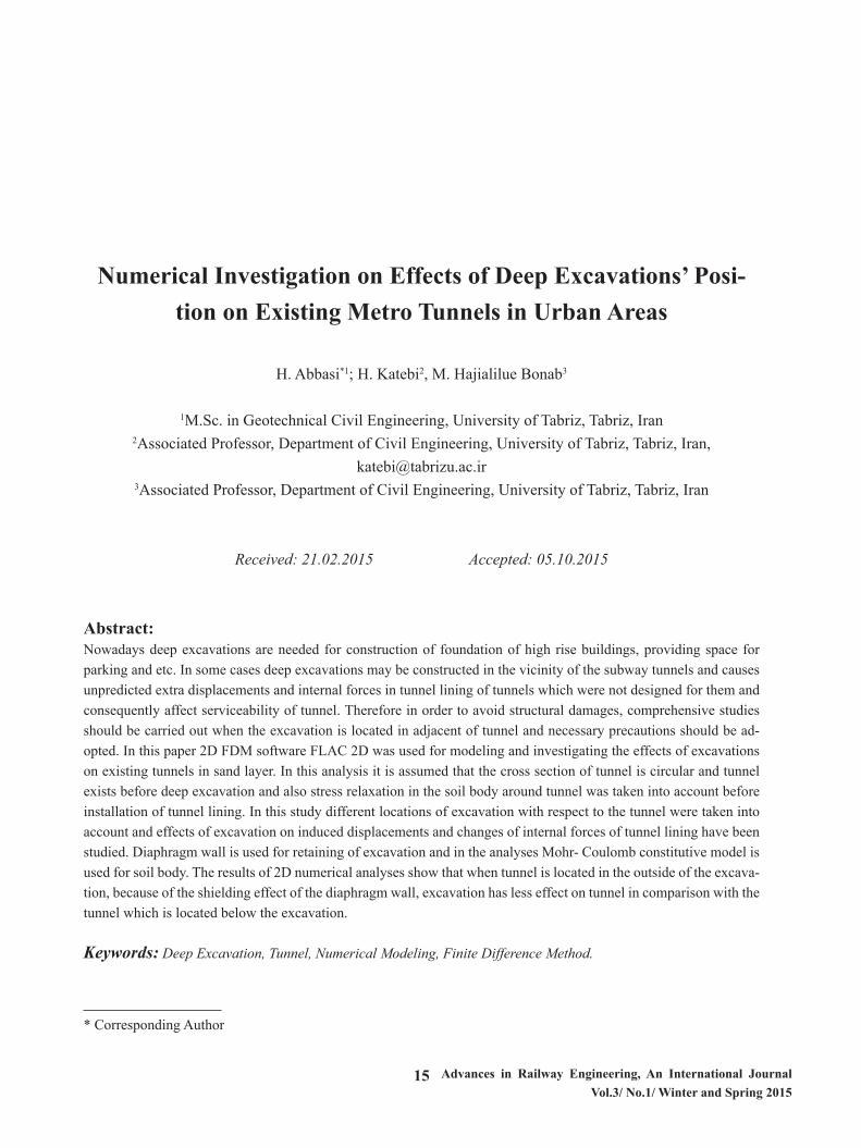
complex soil-structure-interaction problem because of the many different construction processes involved and highly variable ground conditions. It is often difficult to visualize the mechanism of ground deformation around the deep excavation as well as around the existing struc-tures (Karki, 2006).Depending on the relative position of deep excavation and tunnel, response of tunnel to ground movement will be different. Fig. 1 shows the response of tunnel to the movement of surrounding ground when the excavation is located beside and above the tunnel.When the excavation is located beside the tunnel, retain-ing wall and the soil behind the wall move towards the excavation pit and consequently cause the tunnel lining moves towards the excavation. The movement of tunnel is accompanied by horizontal unloading so the horizontal stress at tunnel spring be-comes smaller and results in distortion of tunnel lining. Similarly vertical movements and unloading is occurred when the excavation pit is constructed above the tunnel. During excavation, vertical unloading is occurred in the bottom of pit and causes the bottom of excavation to heave. Consequently soil and tunnel under excavation move upward and circular cross section of tunnel distorted to oval-shaped.So the effect of deep excavation on tunnel is taken into account in two aspects: 1- Displacements of tunnel lining 2- Distortion of tunnel lining In the current study, only the influence of deep excava-tion on displacements of tunnel lining was investigated in uniform sand soils layer.
3
Depending on the relative position of deep excavation and tunnel, response of tunnel to ground movement will be different. Fig. 1 shows the response of tunnel to the movement of surrounding ground when the excavation is located beside and above the tunnel. When the excavation is located beside the tunnel, retaining wall and the soil behind the wall move towards the excavation pit and consequently cause the tunnel lining moves towards the excavation. The movement of tunnel is accompanied by horizontal unloading so the horizontal stress at tunnel spring becomes smaller and results in distortion of tunnel lining. Similarly vertical movements and unloading is occurred when the excavation pit is constructed above the tunnel. During excavation, vertical unloading is occurred in the bottom of pit and causes the bottom of excavation to heave. Consequently soil and tunnel under excavation move upward and circular cross section of tunnel distorted to oval-shaped. So the effect of deep excavation on tunnel is taken into account in two aspects:
1) Displacements of tunnel lining 2) Distortion of tunnel lining
In the current study, only the influence of deep excavation on displacements of tunnel lining was investigated in uniform sand soils layer.
Fig 1. Displacement and distortion of tunnel lining due to adjacent excavation.
MRT Corporation’s Code of Practice for Railway Protection does not allow the construction work in close distance of the tunnels that can displace the tunnels by more than 15 mm. According to codes in order to safe operation of subway tunnels, allowable deformations of existing tunnel are specified and includes (Sharma et al., 2001):
1) the absolute displacement of tunnel should be less than 20 mm; 2) the heave displacement of tunnel invert should be less than 15 mm; 3) The distortion ratio should be less than 1/2500. So it is important to control the displacements of tunnel lining and deformation of surrounding soil mass in
construction phase of excavation. 3. Materials and soil parameters 3.1. Constitutive model for soil
In the analysis, in order to model the soil, Mohr- Coulomb constitutive model is adopted. This model is an elastic- perfectly plastic model and in general, soil modeled with Mohr- Coulomb model behaves linearly in elastic range. This does not present realistic behavior of soil, nevertheless it is a simple model that has been used most widely over the past years. Mohr- Coulomb model includes five parameters: two of them (Young’s modulus, E and Poisson’s ratio, v) define stress- strain behavior of soil. There are two strength parameters that define failure criteria (cohesion, C and the friction angle, φ) and also a parameter (dilation angle, ψ) that is used for modeling the volume changes in the shearing (Ti et al., 2009). 3.2. Soil parameters
Soil used in numerical modeling was Berlin sand and parameters for that are presented in Table 1. where K0 is the Coefficient of lateral earth pressure at rest and is estimated by following relation known as Jaky’s relation:
Fig 1. Displacement and distortion of tunnel lining due to adjacent excavation.
MRT Corporation’s Code of Practice for Railway Pro-tection does not allow the construction work in close distance of the tunnels that can displace the tunnels by more than 15 mm. According to codes in order to safe operation of subway tunnels, allowable deformations of existing tunnel are specified and includes (Sharma et al., 2001):1- the absolute displacement of tunnel should be less than 20 mm; 2- the heave displacement of tunnel invert should be less than 15 mm; 3- The distortion ratio should be less than 1/2500.So it is important to control the displacements of tunnel lining and deformation of surrounding soil mass in con-struction phase of excavation.
3. Materials and soil parameters3.1. Constitutive model for soilIn the analysis, in order to model the soil, Mohr- Cou-lomb constitutive model is adopted. This model is an elastic- perfectly plastic model and in general, soil modeled with Mohr- Coulomb model be-haves linearly in elastic range. This does not present realistic behavior of soil, neverthe-less it is a simple model that has been used most widely over the past years.Mohr- Coulomb model includes five parameters: two of them (Young’s modulus, E and Poisson’s ratio, ) define stress- strain behavior of soil. There are two strength pa-rameters that define failure criteria (cohesion, C and the friction angle, ) and also a parameter (dilation angle,) that is used for modeling the volume changes in the shearing (Ti et al., 2009).
3.2. Soil parametersSoil used in numerical modeling was Berlin sand and pa-rameters for that are presented in Table 1. where is the Coefficient of lateral earth pressure at rest and is estimated by following relation known as Jaky’s relation:
4
K0 = 1 − sinφ (1) In the literature Poisson’s ratio for Berlin sand has not been presented and Poisson’s ratio vs = 0.3 is assumed for medium dense sand according to Table 2.
Table 1. Berlin sand parameters (Schweiger, 2002)
Soil type 𝛄𝛄
𝐊𝐊𝐊𝐊 𝐦𝐦𝟑𝟑⁄ 𝛄𝛄𝐬𝐬𝐬𝐬𝐬𝐬
𝐊𝐊𝐊𝐊 𝐦𝐦𝟑𝟑⁄ 𝛗𝛗
𝐂𝐂 𝐊𝐊𝐊𝐊 𝐦𝐦𝟐𝟐⁄
𝛙𝛙 𝐊𝐊𝟎𝟎 𝐯𝐯𝐬𝐬
Medium dense sand 19 20 35 0 5 0.426 0.3
Table 2. Poisson’s ratio for granular soil (Das, 2008) Soil type Range of Poisson’s ratio
Loose sand 0.2- 0.4 Medium dense sand 0.25- 0.4
Dense sand 0.3- 0.45 Silty sand 0.2- 0.4
Sand and gravel 0.15- 0.35 The dilation angle was determined by the following expression:
ψ ≈ φ − 30 (2)
where φ is the internal friction angle of granular soil (Khoiri, 2013). Variable Young’s modulus with respect to depth is assigned for uniform Berlin sand according to following relations (Schweiger, 2002):
Es = 20000√Z (KPa) for 0 < Z < 20m Es = 60000√Z (KPa) for Z > 20m
where Z is depth below surface. 3.3. Diaphragm wall and tunnel lining parameters
The diaphragm wall as a retaining system is used for stability of excavation pit. The thickness of the diaphragm wall is 0.80 m and its depth is 25 m. Table 3. shows required parameters for numerical modeling of wall. The wall’s parameters are adopted from an excavation project in Berlin that presented for studying and research purpose (Schweiger, 2002).
Also, the dimensions and geometric properties of tunnel in current study are selected based on 2nd Line of Tabriz Metro Tunnel properties. This Subway line is designed as a single tunnel and constructing by tunnel boring machine (TBM).
It is assumed that cross section of tunnel is circular and the radius of excavated Tunnel equals 5m. Table 4. shows the parameters of tunnel lining.
The wall and tunnel lining is modeled by beam element.
3.4. Model parameter for soil- structure interaction
(1)In the literature Poisson’s ratio for Berlin sand has not been presented and Poisson’s ratio is assumed for me-dium dense sand according to Table 2.
18Advances in Railway Engineering, An International Journal Vol.3/ No.1/ Winter and Spring 2015
Table 1. Berlin sand parameters (Schweiger, 2002)
4
K0 = 1 − sinφ (1) In the literature Poisson’s ratio for Berlin sand has not been presented and Poisson’s ratio vs = 0.3 is assumed for medium dense sand according to Table 2.
Table 1. Berlin sand parameters (Schweiger, 2002)
Soil type 𝛄𝛄
𝐊𝐊𝐊𝐊 𝐦𝐦𝟑𝟑⁄ 𝛄𝛄𝐬𝐬𝐬𝐬𝐬𝐬
𝐊𝐊𝐊𝐊 𝐦𝐦𝟑𝟑⁄ 𝛗𝛗
𝐂𝐂 𝐊𝐊𝐊𝐊 𝐦𝐦𝟐𝟐⁄
𝛙𝛙 𝐊𝐊𝟎𝟎 𝐯𝐯𝐬𝐬
Medium dense sand 19 20 35 0 5 0.426 0.3
Table 2. Poisson’s ratio for granular soil (Das, 2008) Soil type Range of Poisson’s ratio
Loose sand 0.2- 0.4 Medium dense sand 0.25- 0.4
Dense sand 0.3- 0.45 Silty sand 0.2- 0.4
Sand and gravel 0.15- 0.35 The dilation angle was determined by the following expression:
ψ ≈ φ − 30 (2)
where φ is the internal friction angle of granular soil (Khoiri, 2013). Variable Young’s modulus with respect to depth is assigned for uniform Berlin sand according to following relations (Schweiger, 2002):
Es = 20000√Z (KPa) for 0 < Z < 20m Es = 60000√Z (KPa) for Z > 20m
where Z is depth below surface. 3.3. Diaphragm wall and tunnel lining parameters
The diaphragm wall as a retaining system is used for stability of excavation pit. The thickness of the diaphragm wall is 0.80 m and its depth is 25 m. Table 3. shows required parameters for numerical modeling of wall. The wall’s parameters are adopted from an excavation project in Berlin that presented for studying and research purpose (Schweiger, 2002).
Also, the dimensions and geometric properties of tunnel in current study are selected based on 2nd Line of Tabriz Metro Tunnel properties. This Subway line is designed as a single tunnel and constructing by tunnel boring machine (TBM).
It is assumed that cross section of tunnel is circular and the radius of excavated Tunnel equals 5m. Table 4. shows the parameters of tunnel lining.
The wall and tunnel lining is modeled by beam element.
3.4. Model parameter for soil- structure interaction
Table 2. Poisson’s ratio for granular soil (Das, 2008)
4
K0 = 1 − sinφ (1) In the literature Poisson’s ratio for Berlin sand has not been presented and Poisson’s ratio vs = 0.3 is assumed for medium dense sand according to Table 2.
Table 1. Berlin sand parameters (Schweiger, 2002)
Soil type 𝛄𝛄
𝐊𝐊𝐊𝐊 𝐦𝐦𝟑𝟑⁄ 𝛄𝛄𝐬𝐬𝐬𝐬𝐬𝐬
𝐊𝐊𝐊𝐊 𝐦𝐦𝟑𝟑⁄ 𝛗𝛗
𝐂𝐂 𝐊𝐊𝐊𝐊 𝐦𝐦𝟐𝟐⁄
𝛙𝛙 𝐊𝐊𝟎𝟎 𝐯𝐯𝐬𝐬
Medium dense sand 19 20 35 0 5 0.426 0.3
Table 2. Poisson’s ratio for granular soil (Das, 2008) Soil type Range of Poisson’s ratio
Loose sand 0.2- 0.4 Medium dense sand 0.25- 0.4
Dense sand 0.3- 0.45 Silty sand 0.2- 0.4
Sand and gravel 0.15- 0.35 The dilation angle was determined by the following expression:
ψ ≈ φ − 30 (2)
where φ is the internal friction angle of granular soil (Khoiri, 2013). Variable Young’s modulus with respect to depth is assigned for uniform Berlin sand according to following relations (Schweiger, 2002):
Es = 20000√Z (KPa) for 0 < Z < 20m Es = 60000√Z (KPa) for Z > 20m
where Z is depth below surface. 3.3. Diaphragm wall and tunnel lining parameters
The diaphragm wall as a retaining system is used for stability of excavation pit. The thickness of the diaphragm wall is 0.80 m and its depth is 25 m. Table 3. shows required parameters for numerical modeling of wall. The wall’s parameters are adopted from an excavation project in Berlin that presented for studying and research purpose (Schweiger, 2002).
Also, the dimensions and geometric properties of tunnel in current study are selected based on 2nd Line of Tabriz Metro Tunnel properties. This Subway line is designed as a single tunnel and constructing by tunnel boring machine (TBM).
It is assumed that cross section of tunnel is circular and the radius of excavated Tunnel equals 5m. Table 4. shows the parameters of tunnel lining.
The wall and tunnel lining is modeled by beam element.
3.4. Model parameter for soil- structure interaction
The dilation angle was determined by the following ex-pression:
4
K0 = 1 − sinφ (1) In the literature Poisson’s ratio for Berlin sand has not been presented and Poisson’s ratio vs = 0.3 is assumed for medium dense sand according to Table 2.
Table 1. Berlin sand parameters (Schweiger, 2002)
Soil type 𝛄𝛄
𝐊𝐊𝐊𝐊 𝐦𝐦𝟑𝟑⁄ 𝛄𝛄𝐬𝐬𝐬𝐬𝐬𝐬
𝐊𝐊𝐊𝐊 𝐦𝐦𝟑𝟑⁄ 𝛗𝛗
𝐂𝐂 𝐊𝐊𝐊𝐊 𝐦𝐦𝟐𝟐⁄
𝛙𝛙 𝐊𝐊𝟎𝟎 𝐯𝐯𝐬𝐬
Medium dense sand 19 20 35 0 5 0.426 0.3
Table 2. Poisson’s ratio for granular soil (Das, 2008) Soil type Range of Poisson’s ratio
Loose sand 0.2- 0.4 Medium dense sand 0.25- 0.4
Dense sand 0.3- 0.45 Silty sand 0.2- 0.4
Sand and gravel 0.15- 0.35 The dilation angle was determined by the following expression:
ψ ≈ φ − 30 (2)
where φ is the internal friction angle of granular soil (Khoiri, 2013). Variable Young’s modulus with respect to depth is assigned for uniform Berlin sand according to following relations (Schweiger, 2002):
Es = 20000√Z (KPa) for 0 < Z < 20m Es = 60000√Z (KPa) for Z > 20m
where Z is depth below surface. 3.3. Diaphragm wall and tunnel lining parameters
The diaphragm wall as a retaining system is used for stability of excavation pit. The thickness of the diaphragm wall is 0.80 m and its depth is 25 m. Table 3. shows required parameters for numerical modeling of wall. The wall’s parameters are adopted from an excavation project in Berlin that presented for studying and research purpose (Schweiger, 2002).
Also, the dimensions and geometric properties of tunnel in current study are selected based on 2nd Line of Tabriz Metro Tunnel properties. This Subway line is designed as a single tunnel and constructing by tunnel boring machine (TBM).
It is assumed that cross section of tunnel is circular and the radius of excavated Tunnel equals 5m. Table 4. shows the parameters of tunnel lining.
The wall and tunnel lining is modeled by beam element.
3.4. Model parameter for soil- structure interaction
(2)
where is the internal friction angle of granular soil (Kho-iri, 2013).Variable Young’s modulus with respect to depth is as-signed for uniform Berlin sand according to following relations (Schweiger, 2002):
4
K0 = 1 − sinφ (1) In the literature Poisson’s ratio for Berlin sand has not been presented and Poisson’s ratio vs = 0.3 is assumed for medium dense sand according to Table 2.
Table 1. Berlin sand parameters (Schweiger, 2002)
Soil type 𝛄𝛄
𝐊𝐊𝐊𝐊 𝐦𝐦𝟑𝟑⁄ 𝛄𝛄𝐬𝐬𝐬𝐬𝐬𝐬
𝐊𝐊𝐊𝐊 𝐦𝐦𝟑𝟑⁄ 𝛗𝛗
𝐂𝐂 𝐊𝐊𝐊𝐊 𝐦𝐦𝟐𝟐⁄
𝛙𝛙 𝐊𝐊𝟎𝟎 𝐯𝐯𝐬𝐬
Medium dense sand 19 20 35 0 5 0.426 0.3
Table 2. Poisson’s ratio for granular soil (Das, 2008) Soil type Range of Poisson’s ratio
Loose sand 0.2- 0.4 Medium dense sand 0.25- 0.4
Dense sand 0.3- 0.45 Silty sand 0.2- 0.4
Sand and gravel 0.15- 0.35 The dilation angle was determined by the following expression:
ψ ≈ φ − 30 (2)
where φ is the internal friction angle of granular soil (Khoiri, 2013). Variable Young’s modulus with respect to depth is assigned for uniform Berlin sand according to following relations (Schweiger, 2002):
Es = 20000√Z (KPa) for 0 < Z < 20m Es = 60000√Z (KPa) for Z > 20m
where Z is depth below surface. 3.3. Diaphragm wall and tunnel lining parameters
The diaphragm wall as a retaining system is used for stability of excavation pit. The thickness of the diaphragm wall is 0.80 m and its depth is 25 m. Table 3. shows required parameters for numerical modeling of wall. The wall’s parameters are adopted from an excavation project in Berlin that presented for studying and research purpose (Schweiger, 2002).
Also, the dimensions and geometric properties of tunnel in current study are selected based on 2nd Line of Tabriz Metro Tunnel properties. This Subway line is designed as a single tunnel and constructing by tunnel boring machine (TBM).
It is assumed that cross section of tunnel is circular and the radius of excavated Tunnel equals 5m. Table 4. shows the parameters of tunnel lining.
The wall and tunnel lining is modeled by beam element.
3.4. Model parameter for soil- structure interaction
where Z is depth below surface.
3.3. Diaphragm wall and tunnel lining parametersThe diaphragm wall as a retaining system is used for stabil-ity of excavation pit. The thickness of the diaphragm wall is 0.80 m and its depth is 25 m. Table 3. shows required parameters for numerical modeling of wall.The wall’s pa-rameters are adopted from an excavation project in Berlin that presented for studying and research purpose (Schwei-ger, 2002).Also, the dimensions and geometric properties of tunnel in current study are selected based on 2nd Line of Tabriz Metro Tunnel properties. This Subway line is de-signed as a single tunnel and constructing by tunnel boring machine (TBM).It is assumed that cross section of tunnel is circular and the radius of excavated Tunnel equals 5m. Table 4. shows the parameters of tunnel lining.The wall and tunnel lining is modeled by beam element.
3.4. Model parameter for soil- structure interactionThere are several instances in geomechanics in which it is desirable to represent planes on which sliding or separa-
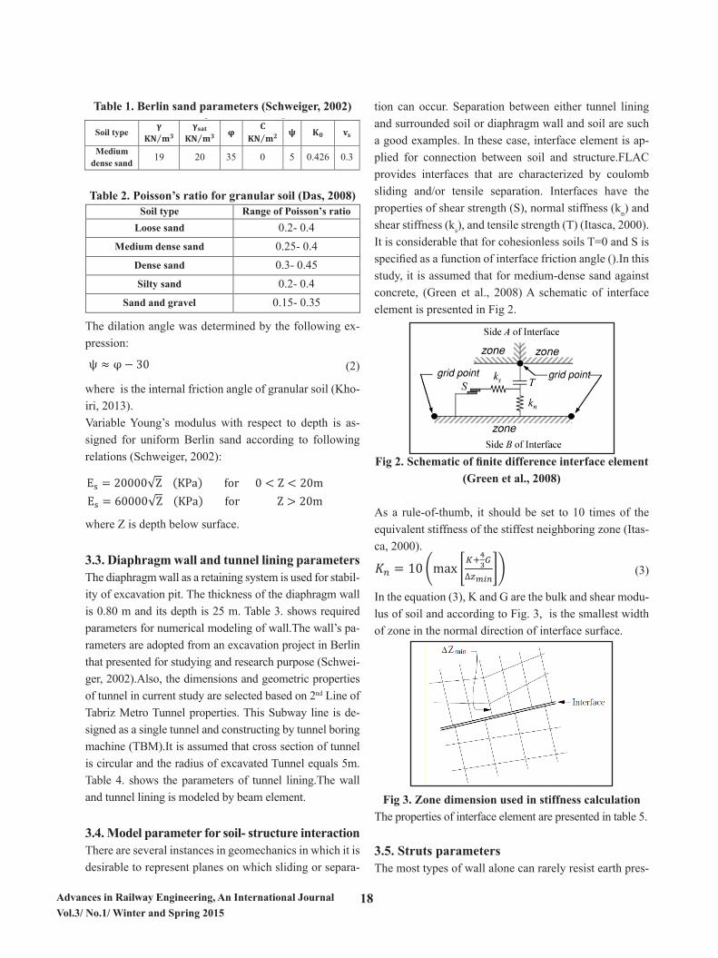
tion can occur. Separation between either tunnel lining and surrounded soil or diaphragm wall and soil are such a good examples. In these case, interface element is ap-plied for connection between soil and structure.FLAC provides interfaces that are characterized by coulomb sliding and/or tensile separation. Interfaces have the properties of shear strength (S), normal stiffness (kn) and shear stiffness (ks), and tensile strength (T) (Itasca, 2000). It is considerable that for cohesionless soils T=0 and S is specified as a function of interface friction angle ().In this study, it is assumed that for medium-dense sand against concrete, (Green et al., 2008) A schematic of interface element is presented in Fig 2.
5
There are several instances in geomechanics in which it is desirable to represent planes on which sliding or separation can occur. Separation between either tunnel lining and surrounded soil or diaphragm wall and soil are such a good examples. In these case, interface element is applied for connection between soil and structure.
FLAC provides interfaces that are characterized by coulomb sliding and/or tensile separation. Interfaces have the properties of shear strength (S), normal stiffness (kn) and shear stiffness (ks), and tensile strength (T) (Itasca, 2000). It is considerable that for cohesionless soils T=0 and S is specified as a function of interface friction angle (𝜑𝜑𝑖𝑖𝑖𝑖𝑖𝑖𝑖𝑖𝑖𝑖𝑖𝑖𝑖𝑖𝑖𝑖𝑖𝑖 =𝛿𝛿). In this study, it is assumed that for medium-dense sand against concrete, 𝛿𝛿 = 31(Green et al., 2008) A schematic of interface element is presented in Fig 2.
Fig 2. Schematic of finite difference interface element (Green et al., 2008)
As a rule-of-thumb, it should be set to 10 times of the equivalent stiffness of the stiffest neighboring zone (Itasca,
2000).
𝐾𝐾𝑖𝑖 = 10(max [𝐾𝐾+43𝐺𝐺
∆𝑧𝑧𝑚𝑚𝑚𝑚𝑚𝑚]) (3)
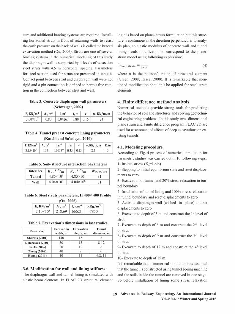
In the equation (3), K and G are the bulk and shear modulus of soil and according to Fig. 3, ∆𝑧𝑧𝑚𝑚𝑖𝑖𝑖𝑖 is the smallest width of zone in the normal direction of interface surface.
Fig 3. Zone dimension used in stiffness calculation
The properties of interface element are presented in table 5. 3.5. Struts parameters
The most types of wall alone can rarely resist earth pressure and additional bracing systems are required. Installing horizontal struts in front of retaining walls to resist the earth pressure on the back of walls is called the braced excavation method (Ou, 2006). Struts are one of several bracing systems.
In the numerical modeling of this study the diaphragm wall is supported by 4 levels of w-section steel struts with 4.5 m horizontal spacing. Parameters for steel section used for struts are presented in table 6. Contact point between strut and diaphragm wall were not rigid and a pin connection is defined to permit free rotation in the connection between strut and wall.
Fig 2. Schematic of finite difference interface element (Green et al., 2008)
As a rule-of-thumb, it should be set to 10 times of the equivalent stiffness of the stiffest neighboring zone (Itas-ca, 2000).
5
There are several instances in geomechanics in which it is desirable to represent planes on which sliding or separation can occur. Separation between either tunnel lining and surrounded soil or diaphragm wall and soil are such a good examples. In these case, interface element is applied for connection between soil and structure.
FLAC provides interfaces that are characterized by coulomb sliding and/or tensile separation. Interfaces have the properties of shear strength (S), normal stiffness (kn) and shear stiffness (ks), and tensile strength (T) (Itasca, 2000). It is considerable that for cohesionless soils T=0 and S is specified as a function of interface friction angle (𝜑𝜑𝑖𝑖𝑖𝑖𝑖𝑖𝑖𝑖𝑖𝑖𝑖𝑖𝑖𝑖𝑖𝑖𝑖𝑖 =𝛿𝛿). In this study, it is assumed that for medium-dense sand against concrete, 𝛿𝛿 = 31(Green et al., 2008) A schematic of interface element is presented in Fig 2.
Fig 2. Schematic of finite difference interface element (Green et al., 2008)
As a rule-of-thumb, it should be set to 10 times of the equivalent stiffness of the stiffest neighboring zone (Itasca,
2000).
𝐾𝐾𝑖𝑖 = 10(max [𝐾𝐾+43𝐺𝐺
∆𝑧𝑧𝑚𝑚𝑚𝑚𝑚𝑚]) (3)
In the equation (3), K and G are the bulk and shear modulus of soil and according to Fig. 3, ∆𝑧𝑧𝑚𝑚𝑖𝑖𝑖𝑖 is the smallest width of zone in the normal direction of interface surface.
Fig 3. Zone dimension used in stiffness calculation
The properties of interface element are presented in table 5. 3.5. Struts parameters
The most types of wall alone can rarely resist earth pressure and additional bracing systems are required. Installing horizontal struts in front of retaining walls to resist the earth pressure on the back of walls is called the braced excavation method (Ou, 2006). Struts are one of several bracing systems.
In the numerical modeling of this study the diaphragm wall is supported by 4 levels of w-section steel struts with 4.5 m horizontal spacing. Parameters for steel section used for struts are presented in table 6. Contact point between strut and diaphragm wall were not rigid and a pin connection is defined to permit free rotation in the connection between strut and wall.
(3)
In the equation (3), K and G are the bulk and shear modu-lus of soil and according to Fig. 3, is the smallest width of zone in the normal direction of interface surface.
5
There are several instances in geomechanics in which it is desirable to represent planes on which sliding or separation can occur. Separation between either tunnel lining and surrounded soil or diaphragm wall and soil are such a good examples. In these case, interface element is applied for connection between soil and structure.
FLAC provides interfaces that are characterized by coulomb sliding and/or tensile separation. Interfaces have the properties of shear strength (S), normal stiffness (kn) and shear stiffness (ks), and tensile strength (T) (Itasca, 2000). It is considerable that for cohesionless soils T=0 and S is specified as a function of interface friction angle (𝜑𝜑𝑖𝑖𝑖𝑖𝑖𝑖𝑖𝑖𝑖𝑖𝑖𝑖𝑖𝑖𝑖𝑖𝑖𝑖 =𝛿𝛿). In this study, it is assumed that for medium-dense sand against concrete, 𝛿𝛿 = 31(Green et al., 2008) A schematic of interface element is presented in Fig 2.
Fig 2. Schematic of finite difference interface element (Green et al., 2008)
As a rule-of-thumb, it should be set to 10 times of the equivalent stiffness of the stiffest neighboring zone (Itasca,
2000).
𝐾𝐾𝑖𝑖 = 10(max [𝐾𝐾+43𝐺𝐺
∆𝑧𝑧𝑚𝑚𝑚𝑚𝑚𝑚]) (3)
In the equation (3), K and G are the bulk and shear modulus of soil and according to Fig. 3, ∆𝑧𝑧𝑚𝑚𝑖𝑖𝑖𝑖 is the smallest width of zone in the normal direction of interface surface.
Fig 3. Zone dimension used in stiffness calculation
The properties of interface element are presented in table 5. 3.5. Struts parameters
The most types of wall alone can rarely resist earth pressure and additional bracing systems are required. Installing horizontal struts in front of retaining walls to resist the earth pressure on the back of walls is called the braced excavation method (Ou, 2006). Struts are one of several bracing systems.
In the numerical modeling of this study the diaphragm wall is supported by 4 levels of w-section steel struts with 4.5 m horizontal spacing. Parameters for steel section used for struts are presented in table 6. Contact point between strut and diaphragm wall were not rigid and a pin connection is defined to permit free rotation in the connection between strut and wall.
Fig 3. Zone dimension used in stiffness calculationThe properties of interface element are presented in table 5.
3.5. Struts parametersThe most types of wall alone can rarely resist earth pres-
19 Advances in Railway Engineering, An International Journal Vol.3/ No.1/ Winter and Spring 2015
sure and additional bracing systems are required. Install-ing horizontal struts in front of retaining walls to resist the earth pressure on the back of walls is called the braced excavation method (Ou, 2006). Struts are one of several bracing systems.In the numerical modeling of this study the diaphragm wall is supported by 4 levels of w-section steel struts with 4.5 m horizontal spacing. Parameters for steel section used for struts are presented in table 6. Contact point between strut and diaphragm wall were not rigid and a pin connection is defined to permit free rota-tion in the connection between strut and wall.
Table 3. Concrete diaphragm wall parameters (Schweiger, 2002)
6
Table 3. Concrete diaphragm wall parameters (Schweiger, 2002) 𝐄𝐄, 𝐊𝐊𝐊𝐊 𝐦𝐦𝟐𝟐⁄ 𝐀𝐀 , 𝐦𝐦𝟐𝟐 𝐈𝐈, 𝐦𝐦𝟒𝟒 𝐭𝐭, 𝐦𝐦 𝐯𝐯 𝐰𝐰, 𝐊𝐊𝐊𝐊 𝐦𝐦/𝐦𝐦⁄ 3.00×10⁷ 0.80 0.04267 0.80 0.15 24
Table 4. Tunnel precast concrete lining parameters (Katebi and Sa’adeyn, 2010) 𝐄𝐄, 𝐊𝐊𝐊𝐊 𝐦𝐦𝟐𝟐⁄ 𝐀𝐀 , 𝐦𝐦𝟐𝟐 𝐈𝐈, 𝐦𝐦𝟒𝟒 𝐭𝐭, 𝐦𝐦 𝐯𝐯 𝐰𝐰, 𝐊𝐊𝐊𝐊 𝐦𝐦/𝐦𝐦⁄ 𝐑𝐑, 𝐦𝐦 3.15×10⁷ 0.35 0.00357 0.35 0.15 8.4 5
Table 5. Soil- structure interaction parameters
Interface 𝑲𝑲𝒏𝒏 , 𝑷𝑷𝑷𝑷 𝒎𝒎⁄ 𝑲𝑲𝒔𝒔 , 𝑷𝑷𝑷𝑷 𝒎𝒎⁄ 𝝋𝝋𝒊𝒊𝒏𝒏𝒊𝒊𝒊𝒊𝒊𝒊𝒊𝒊𝑷𝑷𝒊𝒊𝒊𝒊 Tunnel 4.85×10⁹ 4.85×10⁸ 31
Wall 4.04×10⁹ 4.04×10⁸ 31
Table 6. Steel struts parameters, H 400× 400 Profile (Ou, 2006) 𝐄𝐄, 𝐊𝐊𝐊𝐊 𝐦𝐦𝟐𝟐⁄ 𝐀𝐀 , 𝐦𝐦𝟐𝟐 𝐈𝐈𝐱𝐱,𝐜𝐜𝐦𝐦𝟒𝟒 𝛒𝛒,𝐊𝐊𝐊𝐊 𝐦𝐦𝟑𝟑⁄ 2.10×10⁸ 218.69 66621 7850
Table 7. Excavation’s dimensions in last studies
Researcher Excavation width, m
Excavation depth, m
Tunnel diameter, m
Sharma (2001) 140 15 6 Dolazelova (2001) 30 13 8-12
Karki (2006) 20 12 6 Zheng (2008) 40 8 6 Huang (2011) 10 11 6.2, 11
3.6. Modification for wall and lining stiffness
The diaphragm wall and tunnel lining is simulated with elastic beam elements. In FLAC 2D structural element logic is based on plane- stress formulation but this structure is continuous in the direction perpendicular to analysis plan, so elastic modulus of concrete wall and tunnel lining needs modification to correspond to the plane-strain model using following expression: EPlane strain = E
1−υ2 (4) where υ is the poisson’s ration of structural element (Green, 2008; Itasca, 2000). It is remarkable that mentioned modification shouldn’t be applied for steel struts elements. 4. Finite difference method analysis
Numerical methods provide strong tools for predicting the behavior of soil and structures and solving geotechnical engineering problems. In this study two- dimensional plane strain and Finite difference program FLAC 2D are used for assessment of effects of deep excavations on existing tunnels.
Table 4. Tunnel precast concrete lining parameters (Katebi and Sa’adeyn, 2010)
6
Table 3. Concrete diaphragm wall parameters (Schweiger, 2002) 𝐄𝐄, 𝐊𝐊𝐊𝐊 𝐦𝐦𝟐𝟐⁄ 𝐀𝐀 , 𝐦𝐦𝟐𝟐 𝐈𝐈, 𝐦𝐦𝟒𝟒 𝐭𝐭, 𝐦𝐦 𝐯𝐯 𝐰𝐰, 𝐊𝐊𝐊𝐊 𝐦𝐦/𝐦𝐦⁄ 3.00×10⁷ 0.80 0.04267 0.80 0.15 24
Table 4. Tunnel precast concrete lining parameters (Katebi and Sa’adeyn, 2010) 𝐄𝐄, 𝐊𝐊𝐊𝐊 𝐦𝐦𝟐𝟐⁄ 𝐀𝐀 , 𝐦𝐦𝟐𝟐 𝐈𝐈, 𝐦𝐦𝟒𝟒 𝐭𝐭, 𝐦𝐦 𝐯𝐯 𝐰𝐰, 𝐊𝐊𝐊𝐊 𝐦𝐦/𝐦𝐦⁄ 𝐑𝐑, 𝐦𝐦 3.15×10⁷ 0.35 0.00357 0.35 0.15 8.4 5
Table 5. Soil- structure interaction parameters
Interface 𝑲𝑲𝒏𝒏 , 𝑷𝑷𝑷𝑷 𝒎𝒎⁄ 𝑲𝑲𝒔𝒔 , 𝑷𝑷𝑷𝑷 𝒎𝒎⁄ 𝝋𝝋𝒊𝒊𝒏𝒏𝒊𝒊𝒊𝒊𝒊𝒊𝒊𝒊𝑷𝑷𝒊𝒊𝒊𝒊 Tunnel 4.85×10⁹ 4.85×10⁸ 31
Wall 4.04×10⁹ 4.04×10⁸ 31
Table 6. Steel struts parameters, H 400× 400 Profile (Ou, 2006) 𝐄𝐄, 𝐊𝐊𝐊𝐊 𝐦𝐦𝟐𝟐⁄ 𝐀𝐀 , 𝐦𝐦𝟐𝟐 𝐈𝐈𝐱𝐱,𝐜𝐜𝐦𝐦𝟒𝟒 𝛒𝛒,𝐊𝐊𝐊𝐊 𝐦𝐦𝟑𝟑⁄ 2.10×10⁸ 218.69 66621 7850
Table 7. Excavation’s dimensions in last studies
Researcher Excavation width, m
Excavation depth, m
Tunnel diameter, m
Sharma (2001) 140 15 6 Dolazelova (2001) 30 13 8-12
Karki (2006) 20 12 6 Zheng (2008) 40 8 6 Huang (2011) 10 11 6.2, 11
3.6. Modification for wall and lining stiffness
The diaphragm wall and tunnel lining is simulated with elastic beam elements. In FLAC 2D structural element logic is based on plane- stress formulation but this structure is continuous in the direction perpendicular to analysis plan, so elastic modulus of concrete wall and tunnel lining needs modification to correspond to the plane-strain model using following expression: EPlane strain = E
1−υ2 (4) where υ is the poisson’s ration of structural element (Green, 2008; Itasca, 2000). It is remarkable that mentioned modification shouldn’t be applied for steel struts elements. 4. Finite difference method analysis
Numerical methods provide strong tools for predicting the behavior of soil and structures and solving geotechnical engineering problems. In this study two- dimensional plane strain and Finite difference program FLAC 2D are used for assessment of effects of deep excavations on existing tunnels.
Table 5. Soil- structure interaction parameters
6
Table 3. Concrete diaphragm wall parameters (Schweiger, 2002) 𝐄𝐄, 𝐊𝐊𝐊𝐊 𝐦𝐦𝟐𝟐⁄ 𝐀𝐀 , 𝐦𝐦𝟐𝟐 𝐈𝐈, 𝐦𝐦𝟒𝟒 𝐭𝐭, 𝐦𝐦 𝐯𝐯 𝐰𝐰, 𝐊𝐊𝐊𝐊 𝐦𝐦/𝐦𝐦⁄ 3.00×10⁷ 0.80 0.04267 0.80 0.15 24
Table 4. Tunnel precast concrete lining parameters (Katebi and Sa’adeyn, 2010) 𝐄𝐄, 𝐊𝐊𝐊𝐊 𝐦𝐦𝟐𝟐⁄ 𝐀𝐀 , 𝐦𝐦𝟐𝟐 𝐈𝐈, 𝐦𝐦𝟒𝟒 𝐭𝐭, 𝐦𝐦 𝐯𝐯 𝐰𝐰, 𝐊𝐊𝐊𝐊 𝐦𝐦/𝐦𝐦⁄ 𝐑𝐑, 𝐦𝐦 3.15×10⁷ 0.35 0.00357 0.35 0.15 8.4 5
Table 5. Soil- structure interaction parameters
Interface 𝑲𝑲𝒏𝒏 , 𝑷𝑷𝑷𝑷 𝒎𝒎⁄ 𝑲𝑲𝒔𝒔 , 𝑷𝑷𝑷𝑷 𝒎𝒎⁄ 𝝋𝝋𝒊𝒊𝒏𝒏𝒊𝒊𝒊𝒊𝒊𝒊𝒊𝒊𝑷𝑷𝒊𝒊𝒊𝒊 Tunnel 4.85×10⁹ 4.85×10⁸ 31
Wall 4.04×10⁹ 4.04×10⁸ 31
Table 6. Steel struts parameters, H 400× 400 Profile (Ou, 2006) 𝐄𝐄, 𝐊𝐊𝐊𝐊 𝐦𝐦𝟐𝟐⁄ 𝐀𝐀 , 𝐦𝐦𝟐𝟐 𝐈𝐈𝐱𝐱,𝐜𝐜𝐦𝐦𝟒𝟒 𝛒𝛒,𝐊𝐊𝐊𝐊 𝐦𝐦𝟑𝟑⁄ 2.10×10⁸ 218.69 66621 7850
Table 7. Excavation’s dimensions in last studies
Researcher Excavation width, m
Excavation depth, m
Tunnel diameter, m
Sharma (2001) 140 15 6 Dolazelova (2001) 30 13 8-12
Karki (2006) 20 12 6 Zheng (2008) 40 8 6 Huang (2011) 10 11 6.2, 11
3.6. Modification for wall and lining stiffness
The diaphragm wall and tunnel lining is simulated with elastic beam elements. In FLAC 2D structural element logic is based on plane- stress formulation but this structure is continuous in the direction perpendicular to analysis plan, so elastic modulus of concrete wall and tunnel lining needs modification to correspond to the plane-strain model using following expression: EPlane strain = E
1−υ2 (4) where υ is the poisson’s ration of structural element (Green, 2008; Itasca, 2000). It is remarkable that mentioned modification shouldn’t be applied for steel struts elements. 4. Finite difference method analysis
Numerical methods provide strong tools for predicting the behavior of soil and structures and solving geotechnical engineering problems. In this study two- dimensional plane strain and Finite difference program FLAC 2D are used for assessment of effects of deep excavations on existing tunnels.
Table 6. Steel struts parameters, H 400× 400 Profile (Ou, 2006)
6
Table 3. Concrete diaphragm wall parameters (Schweiger, 2002) 𝐄𝐄, 𝐊𝐊𝐊𝐊 𝐦𝐦𝟐𝟐⁄ 𝐀𝐀 , 𝐦𝐦𝟐𝟐 𝐈𝐈, 𝐦𝐦𝟒𝟒 𝐭𝐭, 𝐦𝐦 𝐯𝐯 𝐰𝐰, 𝐊𝐊𝐊𝐊 𝐦𝐦/𝐦𝐦⁄ 3.00×10⁷ 0.80 0.04267 0.80 0.15 24
Table 4. Tunnel precast concrete lining parameters (Katebi and Sa’adeyn, 2010) 𝐄𝐄, 𝐊𝐊𝐊𝐊 𝐦𝐦𝟐𝟐⁄ 𝐀𝐀 , 𝐦𝐦𝟐𝟐 𝐈𝐈, 𝐦𝐦𝟒𝟒 𝐭𝐭, 𝐦𝐦 𝐯𝐯 𝐰𝐰, 𝐊𝐊𝐊𝐊 𝐦𝐦/𝐦𝐦⁄ 𝐑𝐑, 𝐦𝐦 3.15×10⁷ 0.35 0.00357 0.35 0.15 8.4 5
Table 5. Soil- structure interaction parameters
Interface 𝑲𝑲𝒏𝒏 , 𝑷𝑷𝑷𝑷 𝒎𝒎⁄ 𝑲𝑲𝒔𝒔 , 𝑷𝑷𝑷𝑷 𝒎𝒎⁄ 𝝋𝝋𝒊𝒊𝒏𝒏𝒊𝒊𝒊𝒊𝒊𝒊𝒊𝒊𝑷𝑷𝒊𝒊𝒊𝒊 Tunnel 4.85×10⁹ 4.85×10⁸ 31
Wall 4.04×10⁹ 4.04×10⁸ 31
Table 6. Steel struts parameters, H 400× 400 Profile (Ou, 2006) 𝐄𝐄, 𝐊𝐊𝐊𝐊 𝐦𝐦𝟐𝟐⁄ 𝐀𝐀 , 𝐦𝐦𝟐𝟐 𝐈𝐈𝐱𝐱,𝐜𝐜𝐦𝐦𝟒𝟒 𝛒𝛒,𝐊𝐊𝐊𝐊 𝐦𝐦𝟑𝟑⁄ 2.10×10⁸ 218.69 66621 7850
Table 7. Excavation’s dimensions in last studies
Researcher Excavation width, m
Excavation depth, m
Tunnel diameter, m
Sharma (2001) 140 15 6 Dolazelova (2001) 30 13 8-12
Karki (2006) 20 12 6 Zheng (2008) 40 8 6 Huang (2011) 10 11 6.2, 11
3.6. Modification for wall and lining stiffness
The diaphragm wall and tunnel lining is simulated with elastic beam elements. In FLAC 2D structural element logic is based on plane- stress formulation but this structure is continuous in the direction perpendicular to analysis plan, so elastic modulus of concrete wall and tunnel lining needs modification to correspond to the plane-strain model using following expression: EPlane strain = E
1−υ2 (4) where υ is the poisson’s ration of structural element (Green, 2008; Itasca, 2000). It is remarkable that mentioned modification shouldn’t be applied for steel struts elements. 4. Finite difference method analysis
Numerical methods provide strong tools for predicting the behavior of soil and structures and solving geotechnical engineering problems. In this study two- dimensional plane strain and Finite difference program FLAC 2D are used for assessment of effects of deep excavations on existing tunnels.
Table 7. Excavation’s dimensions in last studies
6
Table 3. Concrete diaphragm wall parameters (Schweiger, 2002) 𝐄𝐄, 𝐊𝐊𝐊𝐊 𝐦𝐦𝟐𝟐⁄ 𝐀𝐀 , 𝐦𝐦𝟐𝟐 𝐈𝐈, 𝐦𝐦𝟒𝟒 𝐭𝐭, 𝐦𝐦 𝐯𝐯 𝐰𝐰, 𝐊𝐊𝐊𝐊 𝐦𝐦/𝐦𝐦⁄ 3.00×10⁷ 0.80 0.04267 0.80 0.15 24
Table 4. Tunnel precast concrete lining parameters (Katebi and Sa’adeyn, 2010) 𝐄𝐄, 𝐊𝐊𝐊𝐊 𝐦𝐦𝟐𝟐⁄ 𝐀𝐀 , 𝐦𝐦𝟐𝟐 𝐈𝐈, 𝐦𝐦𝟒𝟒 𝐭𝐭, 𝐦𝐦 𝐯𝐯 𝐰𝐰, 𝐊𝐊𝐊𝐊 𝐦𝐦/𝐦𝐦⁄ 𝐑𝐑, 𝐦𝐦 3.15×10⁷ 0.35 0.00357 0.35 0.15 8.4 5
Table 5. Soil- structure interaction parameters
Interface 𝑲𝑲𝒏𝒏 , 𝑷𝑷𝑷𝑷 𝒎𝒎⁄ 𝑲𝑲𝒔𝒔 , 𝑷𝑷𝑷𝑷 𝒎𝒎⁄ 𝝋𝝋𝒊𝒊𝒏𝒏𝒊𝒊𝒊𝒊𝒊𝒊𝒊𝒊𝑷𝑷𝒊𝒊𝒊𝒊 Tunnel 4.85×10⁹ 4.85×10⁸ 31
Wall 4.04×10⁹ 4.04×10⁸ 31
Table 6. Steel struts parameters, H 400× 400 Profile (Ou, 2006) 𝐄𝐄, 𝐊𝐊𝐊𝐊 𝐦𝐦𝟐𝟐⁄ 𝐀𝐀 , 𝐦𝐦𝟐𝟐 𝐈𝐈𝐱𝐱,𝐜𝐜𝐦𝐦𝟒𝟒 𝛒𝛒,𝐊𝐊𝐊𝐊 𝐦𝐦𝟑𝟑⁄ 2.10×10⁸ 218.69 66621 7850
Table 7. Excavation’s dimensions in last studies
Researcher Excavation width, m
Excavation depth, m
Tunnel diameter, m
Sharma (2001) 140 15 6 Dolazelova (2001) 30 13 8-12
Karki (2006) 20 12 6 Zheng (2008) 40 8 6 Huang (2011) 10 11 6.2, 11
3.6. Modification for wall and lining stiffness
The diaphragm wall and tunnel lining is simulated with elastic beam elements. In FLAC 2D structural element logic is based on plane- stress formulation but this structure is continuous in the direction perpendicular to analysis plan, so elastic modulus of concrete wall and tunnel lining needs modification to correspond to the plane-strain model using following expression: EPlane strain = E
1−υ2 (4) where υ is the poisson’s ration of structural element (Green, 2008; Itasca, 2000). It is remarkable that mentioned modification shouldn’t be applied for steel struts elements. 4. Finite difference method analysis
Numerical methods provide strong tools for predicting the behavior of soil and structures and solving geotechnical engineering problems. In this study two- dimensional plane strain and Finite difference program FLAC 2D are used for assessment of effects of deep excavations on existing tunnels.
3.6. Modification for wall and lining stiffnessThe diaphragm wall and tunnel lining is simulated with elastic beam elements. In FLAC 2D structural element
logic is based on plane- stress formulation but this struc-ture is continuous in the direction perpendicular to analy-sis plan, so elastic modulus of concrete wall and tunnel lining needs modification to correspond to the plane-strain model using following expression:
6
Table 3. Concrete diaphragm wall parameters (Schweiger, 2002) 𝐄𝐄, 𝐊𝐊𝐊𝐊 𝐦𝐦𝟐𝟐⁄ 𝐀𝐀 , 𝐦𝐦𝟐𝟐 𝐈𝐈, 𝐦𝐦𝟒𝟒 𝐭𝐭, 𝐦𝐦 𝐯𝐯 𝐰𝐰, 𝐊𝐊𝐊𝐊 𝐦𝐦/𝐦𝐦⁄ 3.00×10⁷ 0.80 0.04267 0.80 0.15 24
Table 4. Tunnel precast concrete lining parameters (Katebi and Sa’adeyn, 2010) 𝐄𝐄, 𝐊𝐊𝐊𝐊 𝐦𝐦𝟐𝟐⁄ 𝐀𝐀 , 𝐦𝐦𝟐𝟐 𝐈𝐈, 𝐦𝐦𝟒𝟒 𝐭𝐭, 𝐦𝐦 𝐯𝐯 𝐰𝐰, 𝐊𝐊𝐊𝐊 𝐦𝐦/𝐦𝐦⁄ 𝐑𝐑, 𝐦𝐦 3.15×10⁷ 0.35 0.00357 0.35 0.15 8.4 5
Table 5. Soil- structure interaction parameters
Interface 𝑲𝑲𝒏𝒏 , 𝑷𝑷𝑷𝑷 𝒎𝒎⁄ 𝑲𝑲𝒔𝒔 , 𝑷𝑷𝑷𝑷 𝒎𝒎⁄ 𝝋𝝋𝒊𝒊𝒏𝒏𝒊𝒊𝒊𝒊𝒊𝒊𝒊𝒊𝑷𝑷𝒊𝒊𝒊𝒊 Tunnel 4.85×10⁹ 4.85×10⁸ 31
Wall 4.04×10⁹ 4.04×10⁸ 31
Table 6. Steel struts parameters, H 400× 400 Profile (Ou, 2006) 𝐄𝐄, 𝐊𝐊𝐊𝐊 𝐦𝐦𝟐𝟐⁄ 𝐀𝐀 , 𝐦𝐦𝟐𝟐 𝐈𝐈𝐱𝐱,𝐜𝐜𝐦𝐦𝟒𝟒 𝛒𝛒,𝐊𝐊𝐊𝐊 𝐦𝐦𝟑𝟑⁄ 2.10×10⁸ 218.69 66621 7850
Table 7. Excavation’s dimensions in last studies
Researcher Excavation width, m
Excavation depth, m
Tunnel diameter, m
Sharma (2001) 140 15 6 Dolazelova (2001) 30 13 8-12
Karki (2006) 20 12 6 Zheng (2008) 40 8 6 Huang (2011) 10 11 6.2, 11
3.6. Modification for wall and lining stiffness
The diaphragm wall and tunnel lining is simulated with elastic beam elements. In FLAC 2D structural element logic is based on plane- stress formulation but this structure is continuous in the direction perpendicular to analysis plan, so elastic modulus of concrete wall and tunnel lining needs modification to correspond to the plane-strain model using following expression: EPlane strain = E
1−υ2 (4) where υ is the poisson’s ration of structural element (Green, 2008; Itasca, 2000). It is remarkable that mentioned modification shouldn’t be applied for steel struts elements. 4. Finite difference method analysis
Numerical methods provide strong tools for predicting the behavior of soil and structures and solving geotechnical engineering problems. In this study two- dimensional plane strain and Finite difference program FLAC 2D are used for assessment of effects of deep excavations on existing tunnels.
(4)
where υ is the poisson’s ration of structural element (Green, 2008; Itasca, 2000). It is remarkable that men-tioned modification shouldn’t be applied for steel struts elements.
4. Finite difference method analysisNumerical methods provide strong tools for predicting the behavior of soil and structures and solving geotechni-cal engineering problems. In this study two- dimensional plane strain and Finite difference program FLAC 2D are used for assessment of effects of deep excavations on ex-isting tunnels.
4.1. Modeling procedureAccording to Fig. 4 process of numerical simulation for parametric studies was carried out in 10 following steps:1- Insitue str ess (K0=1-sin)2- Stepping to initial equilibrium state and reset displace-ments to zero3- Excavation of tunnel and 20% stress relaxation in tun-nel boundary4- Installation of tunnel lining and 100% stress relaxation in tunnel boundary and reset displacements to zero5- Activate diaphragm wall (wished- in- place) and set displacements to zero6- Excavate to depth of 3 m and construct the 1st level of strut7- Excavate to depth of 6 m and construct the 2nd level of strut8- Excavate to depth of 9 m and construct the 3rd level of strut9- Excavate to depth of 12 m and construct the 4th level of strut10- Excavate to depth of 15 m.It is remarkable that in numerical simulation it is assumed that the tunnel is constructed using tunnel boring machine and the soils inside the tunnel are removed in one stage. So before installation of lining some stress relaxation
20Advances in Railway Engineering, An International Journal Vol.3/ No.1/ Winter and Spring 2015
(20%~ 30%) in tunnel boundaries is occurred (Mirzamo-hammadi, 2010). An evaluation of numerical installa-tion procedures for closed face shield tunnelling based on ground response cure (GRC) indicates that in contrast to open face tunnelling a relatively small stress reduc-tion of around 20–30% is required (Moller and Vermeer, 2008). For simulation of stress relaxation in FLAC 2D first tunnel boundary gridpoints are identified by fixing in x- and y- direction and then x- and y- reaction forces are recovered. Recovered reaction forces are reduced in 20% and after removing previous fixity conditions, 80% reaction forces are applied to tunnel boundary gridpoints in opposite direction and finally tunnel lining is installed and complete relaxation is allowed (100% relaxation) to develop loads in the lining (Itasca, 2000).
7
4.1. Modeling procedure According to Fig. 4 process of numerical simulation for parametric studies was carried out in 10 following steps:
1) Insitue stress (K0=1-sinφ) 2) Stepping to initial equilibrium state and reset displacements to zero 3) Excavation of tunnel and 20% stress relaxation in tunnel boundary 4) Installation of tunnel lining and 100% stress relaxation in tunnel boundary and reset displacements to zero 5) Activate diaphragm wall (wished- in- place) and set displacements to zero 6) Excavate to depth of 3 m and construct the 1st level of strut 7) Excavate to depth of 6 m and construct the 2nd level of strut 8) Excavate to depth of 9 m and construct the 3rd level of strut 9) Excavate to depth of 12 m and construct the 4th level of strut 10) Excavate to depth of 15 m.
It is remarkable that in numerical simulation it is assumed that the tunnel is constructed using tunnel boring machine and the soils inside the tunnel are removed in one stage. So before installation of lining some stress relaxation (20%~ 30%) in tunnel boundaries is occurred (Mirzamohammadi, 2010). An evaluation of numerical installation procedures for closed face shield tunnelling based on ground response cure (GRC) indicates that in contrast to open face tunnelling a relatively small stress reduction of around 20–30% is required (Moller and Vermeer, 2008). For simulation of stress relaxation in FLAC 2D first tunnel boundary gridpoints are identified by fixing in x- and y- direction and then x- and y- reaction forces are recovered. Recovered reaction forces are reduced in 20% and after removing previous fixity conditions, 80% reaction forces are applied to tunnel boundary gridpoints in opposite direction and finally tunnel lining is installed and complete relaxation is allowed (100% relaxation) to develop loads in the lining (Itasca, 2000).
Fig 4. Details of construction and modeling procedure. 4.2. Modeling assumptions
Some assumptions were made in numerical modeling as following:
1) Because this paper only investigates the effects of deep excavation on tunnel so all displacements developed in soil and structural elements due to tunneling and wall construction and displacement due to gravitational loading set to zero before deep excavation.
2) Tunnel lining and diaphragm wall is modeled as wished- in- place, i.e. the deformations of ground during installation of lining and construction of wall are neglected.
3) Linear elastic behavior was assumed for steel struts, concrete diaphragm wall and precast concrete tunnel lining.
4) The mesh size is assumed 1 m× 1 m. 5) The analyses are carried out without the presence of groundwater.
Fig 4. Details of construction and modeling procedure.
4.2. Modeling assumptionsSome assumptions were made in numerical modeling as following:1- Because this paper only investigates the effects of deep excavation on tunnel so all displacements developed in soil and structural elements due to tunneling and wall construction and displacement due to gravitational load-ing set to zero before deep excavation.2- Tunnel lining and diaphragm wall is modeled as wished- in- place, i.e. the deformations of ground dur-ing installation of lining and construction of wall are ne-glected. 3- Linear elastic behavior was assumed for steel struts, con-crete diaphragm wall and precast concrete tunnel lining.4- The mesh size is assumed 1 m× 1 m.5- The analyses are carried out without the presence of groundwater.
6- It is assumed that in the modeling of tunnel lining seg-ments there is no joint between segments and beam ele-ments are considered as continues beam.
4.3. Verification Finally, numerical results from this research were com-pared with the results of Karki, R (2006) and Sharma J. S. (2001) to verify the present numerical model. The results of the FDM-analyses were in good conformity with these results.
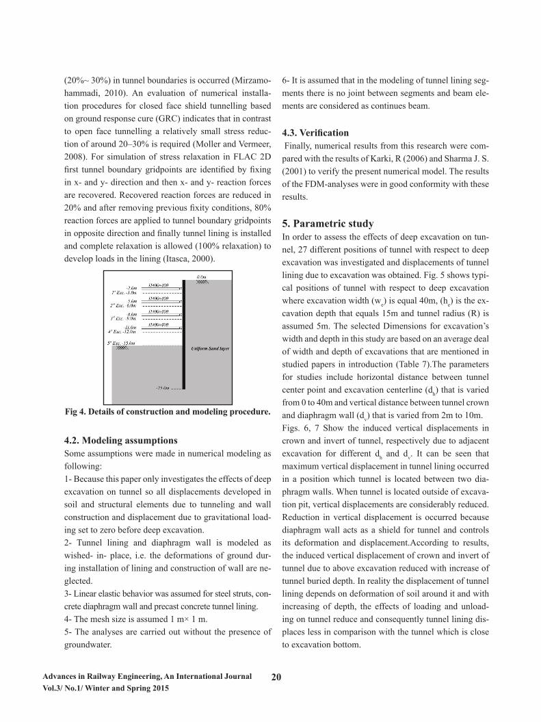
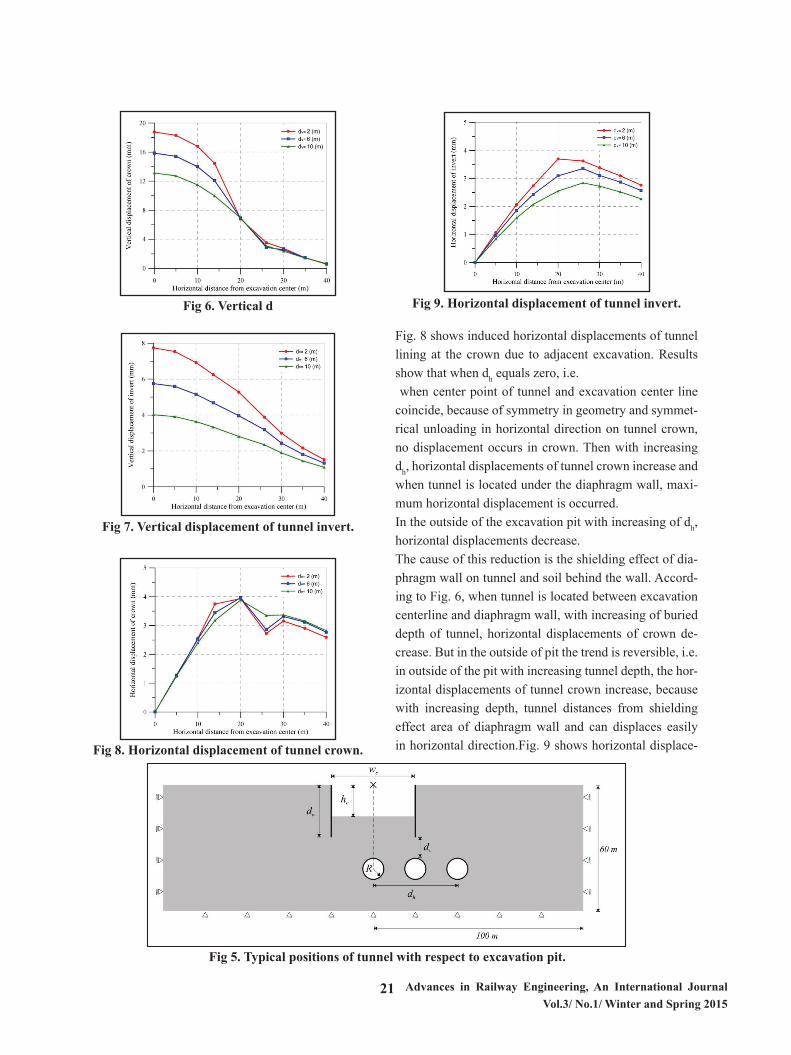
5. Parametric studyIn order to assess the effects of deep excavation on tun-nel, 27 different positions of tunnel with respect to deep excavation was investigated and displacements of tunnel lining due to excavation was obtained. Fig. 5 shows typi-cal positions of tunnel with respect to deep excavation where excavation width (we) is equal 40m, (he) is the ex-cavation depth that equals 15m and tunnel radius (R) is assumed 5m. The selected Dimensions for excavation’s width and depth in this study are based on an average deal of width and depth of excavations that are mentioned in studied papers in introduction (Table 7).The parameters for studies include horizontal distance between tunnel center point and excavation centerline (dh) that is varied from 0 to 40m and vertical distance between tunnel crown and diaphragm wall (dv) that is varied from 2m to 10m.Figs. 6, 7 Show the induced vertical displacements in crown and invert of tunnel, respectively due to adjacent excavation for different dh and dv. It can be seen that maximum vertical displacement in tunnel lining occurred in a position which tunnel is located between two dia-phragm walls. When tunnel is located outside of excava-tion pit, vertical displacements are considerably reduced. Reduction in vertical displacement is occurred because diaphragm wall acts as a shield for tunnel and controls its deformation and displacement.According to results, the induced vertical displacement of crown and invert of tunnel due to above excavation reduced with increase of tunnel buried depth. In reality the displacement of tunnel lining depends on deformation of soil around it and with increasing of depth, the effects of loading and unload-ing on tunnel reduce and consequently tunnel lining dis-places less in comparison with the tunnel which is close to excavation bottom.
21 Advances in Railway Engineering, An International Journal Vol.3/ No.1/ Winter and Spring 2015
10
Fig 6. Vertical displacement of tunnel crown.
Fig 7. Vertical displacement of tunnel invert.
Fig 8. Horizontal displacement of tunnel crown.
Fig 6. Vertical d
isplacement of tunnel crown.
10
Fig 6. Vertical displacement of tunnel crown.
Fig 7. Vertical displacement of tunnel invert.
Fig 8. Horizontal displacement of tunnel crown.
Fig 7. Vertical displacement of tunnel invert.
10
Fig 6. Vertical displacement of tunnel crown.
Fig 7. Vertical displacement of tunnel invert.
Fig 8. Horizontal displacement of tunnel crown.
Fig 8. Horizontal displacement of tunnel crown.
11
Fig 9. Horizontal displacement of tunnel invert.
Fig. 8 shows induced horizontal displacements of tunnel lining at the crown due to adjacent excavation. Results show that when dh equals zero, i.e. when center point of tunnel and excavation center line coincide, because of symmetry in geometry and symmetrical unloading in horizontal direction on tunnel crown, no displacement occurs in crown. Then with increasing dh, horizontal displacements of tunnel crown increase and when tunnel is located under the diaphragm wall, maximum horizontal displacement is occurred. In the outside of the excavation pit with increasing of dh, horizontal displacements decrease. The cause of this reduction is the shielding effect of diaphragm wall on tunnel and soil behind the wall. According to Fig. 6, when tunnel is located between excavation centerline and diaphragm wall, with increasing of buried depth of tunnel, horizontal displacements of crown decrease. But in the outside of pit the trend is reversible, i.e. in outside of the pit with increasing tunnel depth, the horizontal displacements of tunnel crown increase, because with increasing depth, tunnel distances from shielding effect area of diaphragm wall and can displaces easily in horizontal direction.
Fig. 9 shows horizontal displacement of tunnel invert. With comparing Figs. 8, 9, it can be seen that horizontal displacements of tunnel invert are similar to crown’s, when tunnel is located between pit centerline and diaphragm wall. But in the tunnel invert trend of results for positions which tunnel is located in outside of pit are different from crown, i.e. with increasing tunnel depth, the horizontal displacements of invert are reduced either when the tunnel is located inside or outside of the excavation. Because, with increasing the depth of tunnel invert, it gets away from the area in which more horizontal displacements are occurred. Results of the study and comparison between computed displacements and allowable displacements show that considerable displacement is induced in tunnel lining due to adjacent excavation but does not violated from allowable displacement. The investigation of effects of construction of deep excavation adjacent to existing tunnel is a complex soil-structure interaction problem and the amount of displacements of soil and tunnel depend on many factors such as soil stiffness, thickness of tunnel lining and diaphragm wall and etc. So in some cases displacements may be violate allowable displacement. So, for detailed investigation of effects of excavations on existing tunnels further analyses should be carried out. 6. Effects of excavation on the internal forces of tunnel lining Fig. 10 shows the induced shear and axial forces and also bending moment on the tunnel lining due to surrounding soil and other loading on it. As mentioned before, because of deep excavation adjacent to existing tunnel, the stresses of soil around tunnel are disturbed and therefore results in changes in the internal forces of tunnel lining. In order to determine the loading capacity of structural members that are subjected to axial force and bending moment, the interaction curves are used. So, in order to investigate the effects of excavation on the internal forces of adjacent tunnel, the interaction curve for lining section should be calculated and drawn.
Fig 9. Horizontal displacement of tunnel invert.
Fig. 8 shows induced horizontal displacements of tunnel lining at the crown due to adjacent excavation. Results show that when dh equals zero, i.e. when center point of tunnel and excavation center line coincide, because of symmetry in geometry and symmet-rical unloading in horizontal direction on tunnel crown, no displacement occurs in crown. Then with increasing dh, horizontal displacements of tunnel crown increase and when tunnel is located under the diaphragm wall, maxi-mum horizontal displacement is occurred. In the outside of the excavation pit with increasing of dh, horizontal displacements decrease. The cause of this reduction is the shielding effect of dia-phragm wall on tunnel and soil behind the wall. Accord-ing to Fig. 6, when tunnel is located between excavation centerline and diaphragm wall, with increasing of buried depth of tunnel, horizontal displacements of crown de-crease. But in the outside of pit the trend is reversible, i.e. in outside of the pit with increasing tunnel depth, the hor-izontal displacements of tunnel crown increase, because with increasing depth, tunnel distances from shielding effect area of diaphragm wall and can displaces easily in horizontal direction.Fig. 9 shows horizontal displace-
8
6) It is assumed that in the modeling of tunnel lining segments there is no joint between segments and beam elements are considered as continues beam.
4.3 Verification Finally, numerical results from this research were compared with the results of Karki, R (2006) and Sharma J. S. (2001) to verify the present numerical model. The results of the FDM-analyses were in good conformity with these results.
5. Parametric study
In order to assess the effects of deep excavation on tunnel, 27 different positions of tunnel with respect to deep excavation was investigated and displacements of tunnel lining due to excavation was obtained. Fig. 5 shows typical positions of tunnel with respect to deep excavation where excavation width (we) is equal 40m, (he) is the excavation depth that equals 15m and tunnel radius (R) is assumed 5m. The selected Dimensions for excavation’s width and depth in this study are based on an average deal of width and depth of excavations that are mentioned in studied papers in introduction (Table 7).
The parameters for studies include horizontal distance between tunnel center point and excavation centerline (dh) that is varied from 0 to 40m and vertical distance between tunnel crown and diaphragm wall (dv) that is varied from 2m to 10m.
Figs. 6, 7 Show the induced vertical displacements in crown and invert of tunnel, respectively due to adjacent excavation for different dh and dv. It can be seen that maximum vertical displacement in tunnel lining occurred in a position which tunnel is located between two diaphragm walls. When tunnel is located outside of excavation pit, vertical displacements are considerably reduced. Reduction in vertical displacement is occurred because diaphragm wall acts as a shield for tunnel and controls its deformation and displacement.
According to results, the induced vertical displacement of crown and invert of tunnel due to above excavation reduced with increase of tunnel buried depth. In reality the displacement of tunnel lining depends on deformation of soil around it and with increasing of depth, the effects of loading and unloading on tunnel reduce and consequently tunnel lining displaces less in comparison with the tunnel which is close to excavation bottom.
Fig 5. Typical positions of tunnel with respect to excavation pit.Fig 5. Typical positions of tunnel with respect to excavation pit.

22Advances in Railway Engineering, An International Journal Vol.3/ No.1/ Winter and Spring 2015
ment of tunnel invert. With comparing Figs. 8, 9, it can be seen that horizontal displacements of tunnel invert are similar to crown’s, when tunnel is located between pit centerline and diaphragm wall. But in the tunnel invert trend of results for positions which tunnel is located in outside of pit are different from crown, i.e. with increas-ing tunnel depth, the horizontal displacements of invert are reduced either when the tunnel is located inside or outside of the excavation. Because, with increasing the depth of tunnel invert, it gets away from the area in which more horizontal dis-placements are occurred. Results of the study and comparison between computed displacements and allowable displacements show that considerable displacement is induced in tunnel lining due to adjacent excavation but does not violated from allow-able displacement.The investigation of effects of construction of deep exca-vation adjacent to existing tunnel is a complex soil-struc-ture interaction problem and the amount of displacements of soil and tunnel depend on many factors such as soil stiffness, thickness of tunnel lining and diaphragm wall and etc. So in some cases displacements may be violate allowable displacement. So, for detailed investigation of effects of excavations on existing tunnels further analy-ses should be carried out.
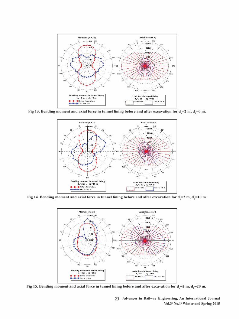
6. Effects of excavation on the internal forces of tunnel liningFig. 10 shows the induced shear and axial forces and also bending moment on the tunnel lining due to surround-ing soil and other loading on it. As mentioned before, be-cause of deep excavation adjacent to existing tunnel, the stresses of soil around tunnel are disturbed and therefore results in changes in the internal forces of tunnel lining.In order to determine the loading capacity of structural members that are subjected to axial force and bending moment, the interaction curves are used. So, in order to investigate the effects of excavation on the internal forces of adjacent tunnel, the interaction curve for lining sec-tion should be calculated and drawn.Figs. 11, 12 Show the precast reinforcement concrete for tunnel lining and its interaction curve, respectively.In order to study the effect of excavation on tunnel, the horizontal distance between tunnel center and excavation
center (dh), is assumed to be 0, 10, 20, 30 and 40 meters. Also it is assumed that the tunnel is located 2 meters be-low the wall.For different positions of tunnel, axial force and bending moment in the lining were calculated before deep exca-vation and after excavation to depth -15.00 meters and results are illustrated in Figs. 13-17.It can be seen from results that the maximum changes and effects on the in-ternal forces of tunnel lining are occurred, when tunnel is located between excavation centerline and diaphragm wall.
12
Figs. 11, 12 Show the precast reinforcement concrete for tunnel lining and its interaction curve, respectively.
In order to study the effect of excavation on tunnel, the horizontal distance between tunnel center and excavation center (dh), is assumed to be 0, 10, 20, 30 and 40 meters. Also it is assumed that the tunnel is located 2 meters below the wall. For different positions of tunnel, axial force and bending moment in the lining were calculated before deep excavation and after excavation to depth -15.00 meters and results are illustrated in Figs. 13-17. It can be seen from results that the maximum changes and effects on the internal forces of tunnel lining are occurred, when tunnel is located between excavation centerline and diaphragm wall.
Fig 10. Induced forces and moment in tunnel lining (Hashash et al., 2001).
Fig 11. Tunnel lining section (Ghasempour, 2008).
Fig 12. Interaction curve for tunnel lining section.
Fig 10. Induced forces and moment in tunnel lining (Hashash et al., 2001).
12
Figs. 11, 12 Show the precast reinforcement concrete for tunnel lining and its interaction curve, respectively.
In order to study the effect of excavation on tunnel, the horizontal distance between tunnel center and excavation center (dh), is assumed to be 0, 10, 20, 30 and 40 meters. Also it is assumed that the tunnel is located 2 meters below the wall. For different positions of tunnel, axial force and bending moment in the lining were calculated before deep excavation and after excavation to depth -15.00 meters and results are illustrated in Figs. 13-17. It can be seen from results that the maximum changes and effects on the internal forces of tunnel lining are occurred, when tunnel is located between excavation centerline and diaphragm wall.
Fig 10. Induced forces and moment in tunnel lining (Hashash et al., 2001).
Fig 11. Tunnel lining section (Ghasempour, 2008).
Fig 12. Interaction curve for tunnel lining section.
Fig 11. Tunnel lining section (Ghasempour, 2008).
12
Figs. 11, 12 Show the precast reinforcement concrete for tunnel lining and its interaction curve, respectively.
In order to study the effect of excavation on tunnel, the horizontal distance between tunnel center and excavation center (dh), is assumed to be 0, 10, 20, 30 and 40 meters. Also it is assumed that the tunnel is located 2 meters below the wall. For different positions of tunnel, axial force and bending moment in the lining were calculated before deep excavation and after excavation to depth -15.00 meters and results are illustrated in Figs. 13-17. It can be seen from results that the maximum changes and effects on the internal forces of tunnel lining are occurred, when tunnel is located between excavation centerline and diaphragm wall.
Fig 10. Induced forces and moment in tunnel lining (Hashash et al., 2001).
Fig 11. Tunnel lining section (Ghasempour, 2008).
Fig 12. Interaction curve for tunnel lining section.Fig 12. Interaction curve for tunnel lining section.
23 Advances in Railway Engineering, An International Journal Vol.3/ No.1/ Winter and Spring 2015
13
Fig 13. Bending moment and axial force in tunnel lining before and after excavation for dv=2 m, dh=0 m.
Fig 14. Bending moment and axial force in tunnel lining before and after excavation for dv=2 m, dh=10 m.
Fig 13. Bending moment and axial force in tunnel lining before and after excavation for dv=2 m, dh=0 m.
13
Fig 13. Bending moment and axial force in tunnel lining before and after excavation for dv=2 m, dh=0 m.
Fig 14. Bending moment and axial force in tunnel lining before and after excavation for dv=2 m, dh=10 m.
Fig 14. Bending moment and axial force in tunnel lining before and after excavation for dv=2 m, dh=10 m.
14
Fig 15. Bending moment and axial force in tunnel lining before and after excavation for dv=2 m, dh=20 m.
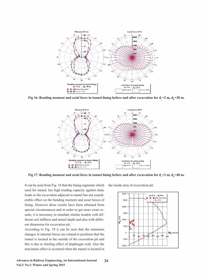
Fig 16. Bending moment and axial force in tunnel lining before and after excavation for dv=2 m, dh=30 m.
Fig 15. Bending moment and axial force in tunnel lining before and after excavation for dv=2 m, dh=20 m.
24Advances in Railway Engineering, An International Journal Vol.3/ No.1/ Winter and Spring 2015
It can be seen from Fig. 18 that the lining segments which used for tunnel, has high loading capacity against static loads so the excavation adjacent to tunnel has not consid-erable effect on the bending moment and axial forces of lining. However these results have been obtained from special circumstances and in order to get more exact re-sults, it is necessary to simulate similar models with dif-ferent soil stiffness and tunnel depth and also with differ-ent dimension for excavation pit.According to Fig. 18 it can be seen that the minimum changes in internal forces are related to positions that the tunnel is located in the outside of the excavation pit and this is due to shieling effect of diaphragm wall. Also the maximum effect is occurred when the tunnel is located in
the inside area of excavation pit.
16
Fig 18. The comparison of internal forces of lining before and after excavation for different positions of tunnel with respect to the excavation.
14
Fig 15. Bending moment and axial force in tunnel lining before and after excavation for dv=2 m, dh=20 m.
Fig 16. Bending moment and axial force in tunnel lining before and after excavation for dv=2 m, dh=30 m.
15
Fig 17. Bending moment and axial force in tunnel lining before and after excavation for dv=2 m, dh=40 m.
It can be seen from Fig. 18 that the lining segments which used for tunnel, has high loading capacity against static loads so the excavation adjacent to tunnel has not considerable effect on the bending moment and axial forces of lining. However these results have been obtained from special circumstances and in order to get more exact results, it is necessary to simulate similar models with different soil stiffness and tunnel depth and also with different dimension for excavation pit.
According to Fig. 18 it can be seen that the minimum changes in internal forces are related to positions that the tunnel is located in the outside of the excavation pit and this is due to shieling effect of diaphragm wall. Also the maximum effect is occurred when the tunnel is located in the inside area of excavation pit.
Fig 16. Bending moment and axial force in tunnel lining before and after excavation for dv=2 m, dh=30 m.
Fig 17. Bending moment and axial force in tunnel lining before and after excavation for dv=2 m, dh=40 m.

25 Advances in Railway Engineering, An International Journal Vol.3/ No.1/ Winter and Spring 2015
16
Fig 18. The comparison of internal forces of lining before and after excavation for different positions of tunnel with respect to the excavation.
16
Fig 18. The comparison of internal forces of lining before and after excavation for different positions of tunnel with respect to the excavation.
16
Fig 18. The comparison of internal forces of lining before and after excavation for different positions of tunnel with respect to the excavation.
16
Fig 18. The comparison of internal forces of lining before and after excavation for different positions of tunnel with respect to the excavation. Fig 18. The comparison of internal forces of lining
before and after excavation for different positions of tunnel with respect to the excavation.
7. Conclusions2D FDM numerical modeling was used in order to in-vestigate the effects of deep excavations on existing tun-nel. Based on the study, following results are obtained; it should be considered that following obtained results are valid only for specific case in which some simplifier assumptions (above mentioned) are applied in numerical simulation.
1) Maximum vertical displacement in crown and invert of tunnel occurs in position which tunnel is located in the center of pit excavation.2) Maximum horizontal displacement in tunnel in-vert occurs when tunnel is located under the diaphragm wall.3) When tunnel is located between two diaphragm walls, with increase in tunnel depth, horizontal displace-ments of invert decreases, but in the outside of excava-tion pit it is reversible.4) In the outside of the excavation, because of shielding effect of diaphragm wall, horizontal displace-ments decrease.5) Considerable influences can be induced in tun-nel lining depending on different soil and structures prop-erties.6) Maximum changes in bending moment and axial forces in tunnel lining are occurred when tunnel is located in inside area of excavation, i.e. between two dia-phragm walls.
References:- Abbasi H (2013) "Investigation of effects of deep exca-vations on tunnel in urban areas", M.Sc. thesis, Univer-sity of Tabriz, Tabriz, Iran.
- Bolton M D (1986) "The Strength and Dilatancy of Sands", Geotechnique 36, No. I.65578.
- Chang C T, Sun C W, Duann S W, Hwang R N (2001) "Response of a Taipei Rapid Transit System (TRTS) tun-nel to adjacent excavation", Tunnelling and Underground Space Technology, 16: 151-158.
- Chen J J, Wang J H, Xiang G W, Wen S L, Du Y (2011) "Numerical Study on the Movement of Existing Tun-

26Advances in Railway Engineering, An International Journal Vol.3/ No.1/ Winter and Spring 2015
nel Due to Deep Excavation in Shanghai", Geotechnical Engineering Journal of the SEAGS & AGSSEA Vol. 42 No.3: 30-40.
- Das B M (2008) "Advanced Soil Mechanics", Taylor & Francis.
- Ding J, Xian Y and Liu T (2012) "Numerical Modeling of Affection of Foundation Pit Excavation on Metro Tun-nel", Advanced Materials Research Vols. 368-37: 2562-2566.
- Dolezalova M (2001) "Tunnel Complex Unloaded by a Deep Excavation", Computers and Geotechnics 28: 469–493.
- Ghasempour N (2008) "Comparing Stability of Single and Twin Tunnels- Case Study of Tabriz Urban Railway Line 2", M.Sc. thesis, University of Tarbiat Modares, Tehran, Iran.
- Green R A, Olgun C G and Cameron W I (2008) "Re-sponse and Modeling of Cantilever Retaining Walls Sub-jected to Seismic Motions", Computer-Aided Civil and Infrastructure Engineering 23:309–322.
- Hashash Y M A, Hook J J, Schmidt B and Yao J I-C (2001) "Seismic design and analysis of underground structures", Tunneling and Underground Space Technol-ogy, Vol. 16: 247- 293.
- Hu Z F, Yue Z Q, Zhou J, and Tham L G (2003) "Design and construction of a deep excavation in soft soils adja-cent to the Shanghai Metro tunnels", Canadian Geotech-nical Journal, 40:933-948.
- Huang X, Schweiger H F and Huang H (2011) "Influ-ence of Deep Excavations on Nearby Existing Tunnels", International Journal of Geomechanics.
- Itasca (2000) "FLAC (Fast Lagrangian Analysis of Con-tinua) User’s Manuals", Itasca Consulting Group, Min-neapolis, MN.
- Katebi H and Sa’adeyn M (2010) "Analysis and pre-diction of ground surface settlement due to tunneling
(Case study: Tabriz 2nd Line of Metro Tunnel)", Journal of Transportation Engineering, V4: 67-75.
- Karki R (2006) "Effects of Deep Excavations on Circu-lar Tunnels in Fine-Grained Soils", MS Thesis. Univer-sity of Saskatchewan, Canada.
- Khoiri, M. and Ou, C-Y. (2013) "Evaluation of Defor-mation Parameter for Deep Excavation in Sand Through Case Histories", Computers and Geotechnics, 47: 57-67.
- Mirzamohammadi mamaghani M (2010) "Investigation of Seismic behavior of Tabriz 2nd Line Subway Structure Under Possible Earthquakes", M.Sc. thesis, University of Tabriz, Tabriz, Iran.
- Moller S C, Vermeer P A (2008) "On numerical simula-tion of tunnel installation", Tunnelling and Underground Space Technology 23: 461–475.
- Ou C-Y (2006) "Deep Excavation: Theory and Prac-tice", Taylor & Francis.
- Schweiger H F (2002) "Results from Numerical Bench-mark Exercises in Geotechnics", Institute for Soil Me-chanics and Foundation Engineering. Graz University of Technology, Austria.
- Sharma, J. S., Hefny, A. M., Zhao, J. and Chan C W (2001) "Effect of Large Excavation on Deformation of Adjacent MRT", Tunnelling and Underground Space Technology 16: 93-98.
- Ti K S, Huat B K, Noorzaei J, Jaafar M S and Sew G S (2009) "A Review of Basic Soil Constitutive Models for Geotechnical Application".
- Zheng G and Wei S W (2008) "Numerical Analyses of Influence of Overlying Pit Excavation on Existing Tun-nels", J. Cent South Univ. T., 15(2): 69-75.