Embed Size (px)
Citation preview
1
Abstract
The effects of ingesting foreign bodies or other
fragments into an engine is a major hazard that
could potentially result in a blade-out event. Due
to the high rotational speeds, an ejected fan
blade can pose an even greater risk than the
original foreign body, necessitating the current
certification requirements. As such a test is
prohibitively expensive, effective computational
analysis to simulate a fan-blade out scenario is
necessary. The current work investigates a fan-
blade out scenario that is consistent with
certification requirements for a modern high-
bypass engine. Emphasis is placed on two casing
designs that incorporate a Kevlar 29 overwrap
while a fully Ti-6Al-4V casing serves as a
baseline. A meso-scale approach is used for the
composite modeling, which is validated against a
ballistic experiment for three different composite
damage theories. In addition to comparing the
response of a conventional and composite fan
casing, the effect of bonding between Kevlar
layers is explored.
1 Introduction
In the event of a foreign body ingestion
scenario, fatigue failure, or manufacturing
defect, a commercial engine must demonstrate
the capability to contain any released blades or
fragments. This test, required by FAR 33.94 [1],
must occur for the stage with the highest blade-
release energy, which is typically the fan blade
for high-bypass engines [2]. However, due to the
extreme cost required to conduct and instrument
such a test, significant research has been directed
toward computationally modeling.
Most early works [3–6] used analytical or
single-blade models to evaluate containment
response for steel cylinders, giving general
approximations of expected casing deformation.
Building on the previous works, Sarkar and
Atluri [7] considered the effect of multi-blade
interactions, discovering that the peak forces
exerted on the casing were approximately twice
as much as predicted by a single-blade study.
Since then, models have progressively become
more complex. Shmotin et al. [8] used a high-
fidelity fan model to investigate computational
modeling effects such as instantaneous blade
release and mesh density. An alternative casing
geometry incorporating a convex curve in the
impact region was proposed by Carney et al. [9]
and found it to have a higher ballistic limit.
Rotational imbalances from blade release have
been shown to play a significant role both
numerically [10] and experimentally [11],
contributing to blade-casing interactions. A
recent FAA report [2] highlighted the importance
of blade tip friction for predicting blade
containment.
In an effort to reduce costs, lightweight
composites have been incorporated into turbofan
engines. Due to the size and weight of the casing,
it has been targeted as a potential way to
significantly reduce costs. As a candidate
material, Kevlar has been widely studied in an
attempt to characterize its behavior for the
purpose of ballistic protection. Its anisotropic
properties, strain-rate dependency, and
inherently multi-scale nature make it a complex
material requiring much experimental
observation. Researchers such as van Hoof,
Cunniff, and Roylance conducted many
experimental tests to characterize the impact
response of Kevlar. Cunniff identified the
longitudinal strain waves that are produced upon
projectile impact, propagating from the impact
zone at the speed of sound through the material
NUMERICAL INVESTIGATION OF FAN-BLADE OUT USING MESO-SCALE COMPOSITE MODELING
Brandon Horton*, Javid Bayandor*
*CRashworthiness for Aerospace Structures and Hybrids (CRASH) Lab, Virginia Tech
Keywords: Fan-blade out, Meso-scale modeling, Softwall casing
HORTON B., BAYANDOR J.
2
[12]. This corroborates earlier observations by
Freeston and Claus [13] that concluded that the
decay of strain waves due to fiber crossover is
very small (reflection coefficient of
approximately 0.01). Roylance also showed that
this small reflectance causes the majority of the
stress to be carried by the principal yarns instead
of the orthogonal yarns [14]. This ability to
involve more material in the impact incident is
what gives Kevlar such high energy absorption
capability, proving it to be a good protective
fabric [15, 16]. Additionally, Kevlar exhibits
limited strain-rate dependency [17], making it
somewhat simpler to model than other composite
fabrics. More recently, Kevlar was extensively
studied specifically for fan casing design in [18,
19].
2 Material Model Theory
Computational analysis requires the use
of material models to describe the structural
response under a load. Models can vary widely in
complexity and computational effort; the
following section details the implementations
used for this study.
2.1 Ti-6Al-4V
Ti-6Al-4V is a commonly used material
in aerospace structures for both fan blades and
containment. As such, significant research has
gone into accurately defining its material
properties and corresponding numerical
representation [20–23]. The Johnson-Cook
model is frequently employed to model the
response of Ti-6Al-4V at high-strain rate
applications, but requires an equation of state and
is computationally expensive.
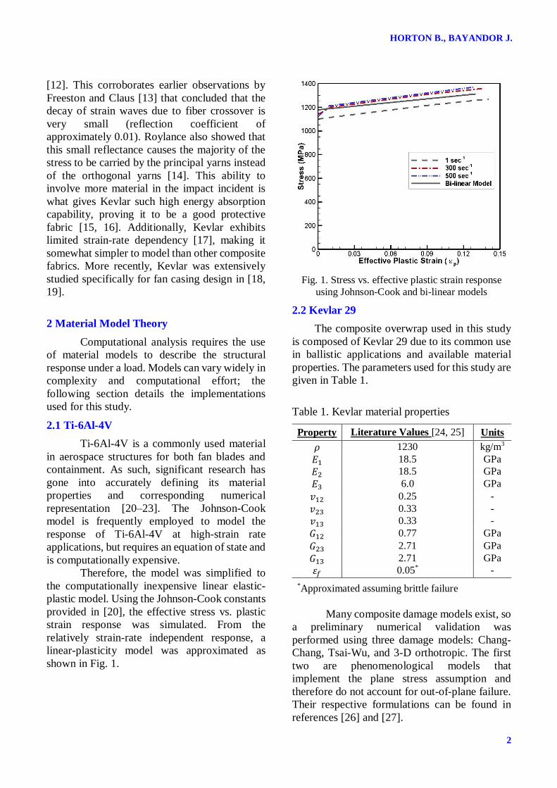
Therefore, the model was simplified to
the computationally inexpensive linear elastic-
plastic model. Using the Johnson-Cook constants
provided in [20], the effective stress vs. plastic
strain response was simulated. From the
relatively strain-rate independent response, a
linear-plasticity model was approximated as
shown in Fig. 1.
Fig. 1. Stress vs. effective plastic strain response
using Johnson-Cook and bi-linear models
2.2 Kevlar 29
The composite overwrap used in this study
is composed of Kevlar 29 due to its common use
in ballistic applications and available material
properties. The parameters used for this study are
given in Table 1.
Table 1. Kevlar material properties
Property Literature Values [24, 25] Units
𝜌 1230 kg/m3
𝐸1 18.5 GPa
𝐸2 18.5 GPa
𝐸3 6.0 GPa
𝑣12 0.25 -
𝑣23 0.33 -
𝑣13 0.33 -
𝐺12 0.77 GPa
𝐺23 2.71 GPa
𝐺13 2.71 GPa
𝜀𝑓 0.05* -
*Approximated assuming brittle failure
Many composite damage models exist, so
a preliminary numerical validation was
performed using three damage models: Chang-
Chang, Tsai-Wu, and 3-D orthotropic. The first
two are phenomenological models that
implement the plane stress assumption and
therefore do not account for out-of-plane failure.
Their respective formulations can be found in
references [26] and [27].
3
NUMERICAL INVESTIGATION OF FAN-BLADE OUT USING MESO-
SCALE COMPOSITE MODELING
Unlike the previously mentioned models,
the 3-D anisotropic model is not based on
phenomenological observations. This model
considers failure in a three-dimensional stress
space where the ultimate failure and damage are
purely driven by strain. The damaged compliance
matrix is given by Equation 1 where 𝐸𝑖𝑗 is
Young's modulus, 𝑣𝑖𝑗 is Poisson's ratio, 𝐺𝑖𝑗 is
shear modulus, and 𝑑𝑖𝑗 is the damage parameter.
This damage parameter is active in both tension
and compression and updates based on the
component strains, as shown in Equation 2:
𝑑𝑖𝑗 = max(𝑑𝑖𝑗; 𝑑𝑖𝑗𝑐 ⟨
𝜀𝑖𝑗 − 𝜀𝑖𝑗𝑡ℎ
𝜀𝑖𝑗𝑐 − 𝜀𝑖𝑗
𝑡ℎ⟩) (2)
where 𝜖𝑖𝑗 is strain, and subscripts 𝑐 and 𝑡ℎ
represent critical and threshold values
respectively. The formulation of the damage
parameter ensures that any damage inflicted
remains present throughout the simulation.
2.3 Epoxy (Tiebreak)
A meso-scale modeling approach is used
for this analysis, allowing delamination to be
explicitly modeled. The separation model used
for this analysis is the Dycoss Discrete Crack
model [28]. This model works in both tension
and compression, with shear (𝜎𝑠 ) and normal
(𝜎𝑛) failure criteria that govern interface strength
as show in Equation 3:
[max(𝜎𝑛, 0)
𝜎𝑁
]
2
+ [𝜎𝑠
𝜎𝑆 − sin(𝜃)min(0, 𝜎𝑛)]2
= 1 (3)
By allowing separation to be calculated on a
continuous scale from 0 to 1, where 0 represents
full adhesion and 1 represents full separation, the
epoxy stretching between interfaces is simulated.
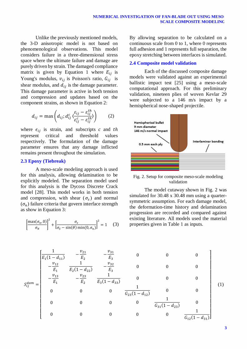
2.4 Composite model validation
Each of the discussed composite damage
models were validated against an experimental
ballistic impact test [25] using a meso-scale
computational approach. For this preliminary
validation, nineteen plies of woven Kevlar 29
were subjected to a 146 m/s impact by a
hemispherical nose-shaped projectile.
Fig. 2. Setup for composite meso-scale modeling
validation
The model cutaway shown in Fig. 2 was
simulated for 30.48 x 30.48 mm using a quarter-
symmetric assumption. For each damage model,
the deformation-time history and delamination
progression are recorded and compared against
existing literature. All models used the material
properties given in Table 1 as inputs.
𝑆𝑖𝑗𝑑𝑎𝑚 =
[
1
𝐸1(1 − 𝑑11)−
𝑣21
𝐸2−
𝑣31
𝐸3
−𝑣12
𝐸1
1
𝐸2(1 − 𝑑22)−
𝑣32
𝐸3
−𝑣13
𝐸1−
𝑣23
𝐸2
1
𝐸3(1 − 𝑑33)
0 0 0
0 0 0
0 0 0
0 0 0
0 0 0
0 0 0
1
𝐺23(1 − 𝑑12)0 0
01
𝐺31(1 − 𝑑23)0
0 01
𝐺12(1 − 𝑑31)]
(1)
HORTON B., BAYANDOR J.
4
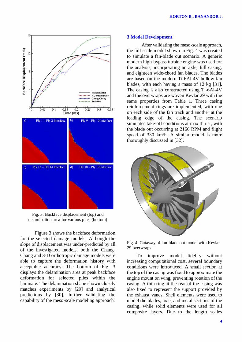
Fig. 3. Backface displacement (top) and
delamination area for various plies (bottom)
Figure 3 shows the backface deformation
for the selected damage models. Although the
slope of displacement was under-predicted by all
of the investigated models, both the Chang-
Chang and 3-D orthotropic damage models were
able to capture the deformation history with
acceptable accuracy. The bottom of Fig. 3
displays the delamination area at peak backface
deformation for selected plies within the
laminate. The delamination shape shown closely
matches experiments by [29] and analytical
predictions by [30], further validating the
capability of the meso-scale modeling approach.
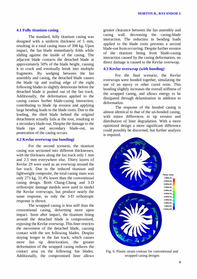
3 Model Development
After validating the meso-scale approach,
the full-scale model shown in Fig. 4 was created
to simulate a fan-blade out scenario. A generic
modern high-bypass turbine engine was used for
the analysis, incorporating an axle, full casing,
and eighteen wide-chord fan blades. The blades
are based on the modern Ti-6Al-4V hollow fan
blades, with each having a mass of 12 kg [31].
The casing is also constructed using Ti-6Al-4V
and the overwraps are woven Kevlar 29 with the
same properties from Table 1. Three casing
reinforcement rings are implemented, with one
on each side of the fan track and another at the
leading edge of the casing. The scenario
simulates take-off conditions at max thrust, with
the blade out occurring at 2166 RPM and flight
speed of 330 km/h. A similar model is more
thoroughly discussed in [32].
Fig. 4. Cutaway of fan-blade out model with Kevlar 29 overwraps
To improve model fidelity without
increasing computational cost, several boundary
conditions were introduced. A small section at
the top of the casing was fixed to approximate the
engine mount on wing, preventing rotation of the
casing. A thin ring at the rear of the casing was
also fixed to represent the support provided by
the exhaust vanes. Shell elements were used to
model the blades, axle, and metal sections of the
casing, while solid elements were used for all
composite layers. Due to the length scales

5
NUMERICAL INVESTIGATION OF FAN-BLADE OUT USING MESO-
SCALE COMPOSITE MODELING
required for such an analysis, each Kevlar
overwrap represents ten plies (0.5 mm each ply),
with a bonding interface between each overwrap.
Without aerodynamic loads, the ejected blade
continues to scrape around the inside of the
casing, artificially producing more damage.
Therefore, upon detachment, an acceleration
based on the expected thrust output is applied to
the free fan-blade. Finally, the rotational speed of
fan assembly is allowed to freely dissipate as the
scenario progresses, simulating an automatic
engine shutdown due to the rotational imbalance.
4 Fan-blade out investigation
Three casing designs were considered for
the fan-blade out analysis: fully titanium casing,
titanium with an un-bonded Kevlar overwrap,
and titanium with a bonded Kevlar overwrap.
The fully titanium casing is used as a baseline
case to compare against for weight and damage
containment. Each of these scenarios represents
potential options for casing design and does not
necessary represent a fully optimized design. The
sequential damage progression for each design is
shown in Fig. 5, with descriptions provided in the
following sections.
Fully Titanium Overlay with no bonding Overlay with bonding
13.5
msec
21.5
msec
30.0
msec
Fig. 5. Sequential damage response for each casing design scenario
HORTON B., BAYANDOR J.
6
4.1 Fully titanium casing
The standard, fully titanium casing was
designed with a uniform thickness of 5 mm,
resulting in a total casing mass of 398 kg. Upon
impact, the fan blade immediately folds while
sliding against the inside of the casing. The
adjacent blade contacts the detached blade at
approximately 50% of the blade height, causing
it to crack and eventually break into multiple
fragments. By wedging between the fan
assembly and casing, the detached blade causes
the blade tip and trailing edge of the eight
following blades to slightly deteriorate before the
detached blade is pushed out of the fan track.
Additionally, the deformation applied to the
casing causes further blade-casing interaction,
contributing to blade tip erosion and applying
large bending loads to the blade roots. Due to the
loading, the third blade behind the original
detachment actually fails at the root, resulting in
a secondary blade-out. Despite the damage to the
blade tips and secondary blade-out, no
penetration of the casing occurs.
4.2 Kevlar overwrap (no bonding)
For the second scenario, the titanium
casing was sectioned into different thicknesses,
with the thickness along the fan track only 1 mm
and 2.5 mm everywhere else. Thirty layers of
Kevlar 29 were used as an overwrap around the
fan track. Due to the reduced titanium and
lightweight composite, the total casing mass was
only 273 kg, 31.4% lower than the conventional
casing design. Both Chang-Chang and 3-D
orthotropic damage models were used to model
the Kevlar overwraps, but produce nearly the
same response, so only the 3-D orthotropic
response is shown.
The wrapped casing is less stiff than the
conventional casing, deforming more upon
impact. Soon after impact, the titanium lining
around the detached blade is compromised,
exposing the Kevlar overwrap. This liner restricts
the movement of the detached blade, causing
contact with the ten following blades. Despite
staying longer in the fan track, which causes
more fan tip deterioration, the greater
deformation of the wrapped casing reduces the
contact area on the following fan blades.
Additionally, the compromised liner allows
greater clearance between the fan assembly and
casing wall, decreasing the casing-blade
interaction. The reduction in bending loads
applied to the blade roots prevents a second
blade-out from occurring. Despite further erosion
of the titanium lining from blade-casing
interaction caused by the casing deformation, no
direct damage is caused to the Kevlar overwrap.
4.3 Kevlar overwrap (with bonding)
For the final scenario, the Kevlar
overwraps were bonded together, simulating the
use of an epoxy or other cured resin. This
bonding slightly increases the overall stiffness of
the wrapped casing, and allows energy to be
dissipated through delamination in addition to
deformation.
The response of the bonded casing is
almost identical to that of the un-bonded casing,
with minor differences in tip erosion and
distribution of liner degradation. With a more
optimized design a more significant difference
could possibly be discerned, but further analysis
is required.
Fig. 6. Plastic strain contour for conventional and
wrapped casing designs
7
NUMERICAL INVESTIGATION OF FAN-BLADE OUT USING MESO-
SCALE COMPOSITE MODELING
4.4 Overall comparison
Both wrapped casing designs provide
lightweight alternatives to the conventional fully
metal casing. In addition to being lightweight, the
wrapped casing designs provide more effective
energy dissipation by having a lower overall
stiffness and allowing the titanium inner lining to
plastically deform and erode. The plastic
deformation of the casing and blades for each
design are displayed in Fig. 6. Due to the similar
response between the two overwrap designs, only
the un-bonded case is shown. Until the secondary
blade detachment for the conventional casing, the
energy dissipation by the casing was 75.4%
greater for the overwrap design than for the fully
titanium casing. By dissipating more kinetic
energy, the loading at the blade roots was
reduced, preventing the secondary blade-out
from occurring.
5 Conclusions
In this study, a fan blade-out scenario
consistent with FAA certification requirements
was simulated using a representative high-bypass
engine. Three casing designs were used, with one
conventional Ti-6Al-4V casing and two softwall,
Kevlar 29 casings. The material models used for
this study were validated against existing
literature before being incorporated into the full-
scale blade-out scenario. By using a bi-linear
titanium material model, computational time was
mitigated while still achieving a close match to
an established Johnson-Cook model. The meso-
scale composite model was successfully
validated against a ballistic experiment for both
Chang-Chang and 3-D orthotropic failure
theories. The full-scale engine model
incorporated eighteen fan blades and a full
casing, allowing for multi-blade interaction.
The conventional casing contained the
fan blade-out event, but produced a secondary
blade-out due to large bending loads imposed at
the blade root from the relatively stiff response.
Despite having 31.4% less mass, the overwrap
casing designs also fully contained the debris.
The overall casing stiffness was lower, leading to
greater deformation upon impact. However,
through the additional casing deformation and
erosion of the titanium inner lining, the overwap
design dissipated 75.4% more energy, reducing
imposed blade root stress and preventing the
secondary blade-out. However, no significant
difference was observed between the un-bonded
and bonded overwrap designs. This could simply
mean that the overwrap casing is over-designed,
but further research is required.
Future work will more thoroughly
investigate each casing design to approach a
more optimized result. Due to the non-linear
nature of composites, a genetic algorithm could
be used to minimize the casing weight while
ensuring debris containment. This could also
allow the effect of overwrap bonding on the
casing to be more clearly defined, potentially
improving ballistic response.
References
[1] Advisory Circular, Engine and Turbosupercharger
Rotor Overspeed Requirements of 14 CFR 33.27.
Federal Aviation Administration, 2011.
[2] K. Sengoz, S. Kan, and A. Eskandarian, “Development of a Generic Gas-Turbine Engine
Fan Blade-Out Full-Fan Rig Model,” 2015.
[3] A. C. Hagg and G. O. Sankey, “The Containment
of Disk Burst Fragments by Cylindrical Shells,” J.
Eng. Power, vol. 96, no. 2, p. 114, 1974.
[4] R. W-H Wu and E. A. Witmerf, “Approximate
Analysis of Containment/Deflection Ring
Responses to Engine Rotor Fragment Impact,” J.
Aircr., vol. 10, no. 1.
[5] J. H. Gerstle, “Analysis of Rotor Fragment Impact
on Ballistic Fabric Engine Burst Containment Shields,” J. Aircr., vol. 12, no. 4.
[6] J. Mathis, S. Parduhn, and P. Alvarez, “Analysis of
turbine engine rotor containment and shielding
structures,” in 29th Joint Propulsion Conference
and Exhibit, 1993.
[7] S. Sarkar and S. N. Atluri, “Effects of multiple
blade interaction on the containment of blade
fragments during a rotor failure,” Finite Elem.
Anal. Des., vol. 23, no. 2–4, pp. 211–223, Nov.
1996.
[8] Y. N. Shmotin, D. V Gabov, A. A. Ryabov, S. S.
Kukanov, and V. N. Rechkin, “Numerical Analysis of Aircraft Engine Fan Blade-Out.”
[9] K. S. Carney, J. M. Pereira, D. M. Revilock, and P.
Matheny, “Jet engine fan blade containment using
an alternate geometry,” Int. J. Impact Eng., vol. 36,
pp. 720–728, 2008.
[10] R. Jain, “Prediction of Transient Loads and
HORTON B., BAYANDOR J.
8
Perforation of Engine Casing During Blade-Off
Event of Fan Rotor Assembly.”
[11] B. Yang, “Blade containment evaluation of civil
aircraft engines,” Chinese J. Aeronaut., vol. 26, no.
1, pp. 9–16, 2013.
[12] P. M. Cunniff, “An Analysis of the System Effects
in Woven Fabrics under Ballistic Impact,” Text.
Res. J., vol. 62, no. 9, pp. 495–509, Sep. 1992.
[13] W. D. Freeston and W. D. Claus, “Strain-Wave
Reflections During Ballistic Impact of Fabric
Panels,” Text. Res. J., vol. 43, no. 6, pp. 348–351, Jun. 1973.
[14] D. Roylance, “Stress wave propagation in fibres:
Effect of crossovers,” Fibre Sci. Technol., vol. 13,
no. 5, pp. 385–395, Aug. 1980.
[15] D. Roylance and S.-S. Wang, “Penetration
Mechanics of Textile Structures.” 1979.
[16] J. E. Field and Q. Sun, “High-speed photographic
study of impact on fibers and woven fabrics,” in
Proceedings of SPIE - The International Society
for Optical Engineering, 1991, vol. 1358, pp. 703–
712.
[17] Y. Wang and Y. M. Xia, “Experimental and
theoretical study on the strain rate and temperature
dependence of mechanical behaviour of Kevlar
fibre,” Compos. Part A Appl. Sci. Manuf., vol. 30,
no. 11, pp. 1251–1257, 1999.
[18] D. Naik, S. Sankaran, B. Mobasher, S. D. Rajan,
and J. M. Pereira, “Development of reliable
modeling methodologies for fan blade out
containment analysis – Part I: Experimental
studies,” Int. J. Impact Eng., vol. 36, no. 1, pp. 1–
11, 2009.
[19] Z. Stahlecker, B. Mobasher, S. D. Rajan, and J. M.
Pereira, “Development of reliable modeling
methodologies for engine fan blade out
containment analysis. Part II: Finite element
analysis,” Int. J. Impact Eng., vol. 36, no. 3, pp.
447–459, 2009.
[20] D. R. Lesuer, “Experimental Investigations of
Material Models for Ti-6Al-4V Titanium and
2024-T3 Aluminum,” 2000.
[21] T. Nicholas, “Dynamic Tensile Testing of
Structural Materials Using a Split Hopkinson Bar
Apparatus.” 1980.
[22] Y. Zhang, J. C. Outeiro, and T. Mabrouki, “On the
Selection of Johnson-cook Constitutive Model
Parameters for Ti-6Al-4V Using Three Types of
Numerical Models of Orthogonal Cutting,”
Procedia CIRP, vol. 31, pp. 112–117, 2015.
[23] R. S. Yatnalkar, A. Gilat, and B. Harper,
“Experimental Investigation of Plastic
Deformation of Ti-6Al-4V under Graduate
Program in Mechanical Engineering,” 2010.
[24] V. Hoof, “Modelling o f Impact Induced
Delamination in,” 1999.
[25] H. L. Gower, D. S. Cronin, and a. Plumtree,
“Ballistic impact response of laminated composite
panels,” Int. J. Impact Eng., vol. 35, no. 9, pp.
1000–1008, 2008.
[26] S. W. Tsai and E. M. Wu, “A General Theory of
Strength for Anisotropic Materials,” J. Compos.
Mater., vol. 5, no. 1, pp. 58–80, 1971.
[27] F.-K. Chang and K.-Y. Chang, “A Progressive Damage Model for Laminated Composites
Containing Stress Concentrations,” J. Compos.
Mater., vol. 21, no. 9, pp. 834–855, Jan. 1987.
[28] P. Lemmen and G. Meijer, “Failure prediction tool
theory and user manual,” 2001.
[29] E. Wu and L.-C. Chang, “Woven glass/epoxy
laminates subject to projectile impact,” Int. J.
Impact Eng., vol. 16, no. 4, pp. 607–619, Aug.
1995.
[30] N. K. Naik, P. Shrirao, and B. C. K. Reddy,
“Ballistic impact behaviour of woven fabric composites: Formulation,” Int. J. Impact Eng., vol.
32, no. 9, pp. 1521–1552, 2006.
[31] “Examination of a Failed Fan Blade Rolls-Royce
RB211 Trent 892 Turbofan Engine Boeing 777-
300, A6-EMM Examination of a Failed Fan Blade
Rolls-Royce RB211 Trent 892 Turbofan Engine
Boeing 777, A6-EMM.”
[32] Y. Song and J. Bayandor, “Analysis of Progressive
Dynamic Damage Caused by Large Hailstone
Ingestion into Modern High Bypass Turbofan
Engine,” in AIAA SciTech 2016, 2016, pp. 1–14.
Contact Author Email Address
Copyright Statement
The authors confirm that they, and/or their company or
organization, hold copyright on all of the original material
included in this paper. The authors also confirm that they
have obtained permission, from the copyright holder of
any third party material included in this paper, to publish
it as part of their paper. The authors confirm that they give permission, or have obtained permission from the
copyright holder of this paper, for the publication and
distribution of this paper as part of the ICAS proceedings
or as individual off-prints from the proceedings.


![AIR COOLED HEAT EXCHANGER [ACHE] FAN BLADE …](https://img.pdfslide.us/doc/110x75/61a8b74bccce2c2f192da0a7/air-cooled-heat-exchanger-ache-fan-blade-.jpg)