Embed Size (px)
Citation preview

447
Proceedings of the IMProVe 2011
International conference on Innovative Methods in Product Design
June 15th – 17th, 2011, Venice, Italy
Numerical fatigue life evaluation of an innovative internal combustion engine shaft
T. Ingrassia (a), G. Lo Buglio (a), E. Lombardo (a), V. Nigrelli (a), G. Sergio (a) (a) Università degli Studi di Palermo – Dipartimento di Ingegneria Chimica, Gestionale, Informatica e Meccanica
Article Information
Keywords: Mechanical design Crankshaft Multiaxial fatigue Finite elements
Corresponding author: Vincenzo Nigrelli Tel.: 0039 091 6657148 Fax.: 0039 091 484334 e-mail: [email protected] Address: viale delle Scienze – Edificio 8 – 90128 Palermo (Italy)
Abstract
A novel self-balanced internal combustion engine is presented. The new engine has a modular structure composed of two cylinders arranged in opposite way. It is characterized by an innovative system of linking between the pistons and the shaft, which has three toggles. One of these is on the middle of the shaft, whereas the others two are placed symmetrically. Thanks to this particular shape of the shaft, the pistons can move with the same timing and so the new engine comes back to be perfectly auto-balanced. Moreover, the fatigue life prediction of the shaft has been studied through numerical methods. In particular, two different approaches have been compared to estimate the maximum number of working cycles: the first is based on a “static” resistance criterion, the second considers the multiaxial nature of the stress and is based on the maximum shear stress (critical) plane criterion. The stress distribution on the shaft during the usual working conditions has been evaluated by a FEM package. Results highlight that the critical plane approach is more conservative than the “static” one.
1 Introduction The paper presents an innovative self-balanced
internal combustion engine with a modular structure composed of two cylinders arranged in opposite way. The new engine is characterized by an innovative crankshaft shape, that has been subjected to an in-depth study in this work.
The crankshaft, in fact, is one of the most important and stressed machine components. It is subjected to superimposed bending and torsion loading cycles. Moreover, the complexity of the geometry, characterized by remarkable size changes produces high stress concentrations at connectors between the crankpins and its arms.
Such crankshaft portions, subjected to the highest stresses during exercise, represent the regions where fatigue cracks growth is located. Therefore, one the main failure cause of the crankshaft is the result of cumulative fatigue damage processes [1].
Essential requirements in the designing of a such component are performances and reliability but, also, material optimized use and cost reduction. Crankshafts can be designed both for unlimited duration, and for limited working periods, so allowing remarkable improvements in terms of mass and dimensions reduction. The last approach is, usually, used in high-power racing engines, where it is particularly important increasing the engine performances also by reducing the weight of all the components [2].
To ensure high performances and reliability, the search for solutions able to make the system more efficient and compact has involved also the spreading of the simulation methods. These ones, in fact, could correctly consider the mechanism dynamics and reducing the approximations in the component performances evaluation phases. For these reasons, many research activities have been addressed to the setting up of
reliable numerical model to identify critical component sections, determining the stress cycles evolution and implementing it in an appropriate resistance criterion [2].
In this work, to estimate the fatigue life of the crankshaft of the novel internal combustion (IC) engine, two different approaches have been used: the first is based on a “static” (maximum shear-stress) resistance criterion, the second on the stresses multi-axial nature. This criterion is also called as ‘critical plane approach’. It postulates that fatigue cracks birth and propagate in specific planes and that the normal stresses to these planes speed up their growth [3]. The identification of the critical plane, as the one where the maximum shear stress value is calculated, it is appropriate in all those cases where the shear failure mechanisms are predominant.
The research activity has been divided into the following five main steps: a) innovative IC engine designing; b) calculation of the working loads on the crankshaft; c) set up of the FEM models; d) evaluation of the results; e) comparison of the two different methodologies in the crankshaft fatigue life prediction.
2 The new internal combustion engine One of the main problems of the internal combustion
engines is the reduction and the balancing of the inertial forces, so to reduce vibrations and increasing the performances. Usually, internal combustion engines are balanced using different constructive solutions: by arranging the cylinders in a particular way, modelling the crankshaft so to counterbalance the variable loads and inertial moments, or by adding new variable loads, through the use of additional balancing masses. Nevertheless, the mentioned balancing methods do not completely solve the inertial forces problems because either the system is left slightly unbalanced or, even if fully balanced, the efficiency of the engine is reduced because of the additional (energy-wasting) balancing masses. To
448
T. Ingrassia et al. Numerical fatigue life evaluation of an innovative internal combustion engine shaft
June 15th – 17th, 2011, Venice, Italy Proceedings of the IMProVe 2011
overcome these problems, the authors have developed a novel internal combustion engine that has very innovative characteristics as regard the mass distribution, the arrangement of pistons and, consequently, the global balancing.
The new engine has a modular structure composed of two cylinders arranged in opposite way.
Fig. 1 CAD model of the novel crankshaft
The main innovative aspects concern the particular shape of the crankshaft and the linking of the pistons. Fig. 1 shows the CAD model of the novel crankshaft.
Even if similar solutions have been presented in the past, the engine, presented in the paper, is characterized by an innovative system of linking between the pistons and the shaft, that is composed of three crankpins: one of these is on the middle of the shaft, whereas the others two are placed symmetrically.
In detail, the engine is composed of two opposite and symmetric cylinders; one of the two pistons is connected, through a big connecting rod, to the pivot of the central crankpin, whereas the second one is linked to the other two pivots through two small connecting rods. Because the two pistons are identical and the two small connecting rods have a mass equal to the big one, the engine (fig. 2) is intrinsically balanced.
Fig. 2 - Innovative internal combustion engine
In a such internal combustion engine, in fact, the inertial forces of the pistons and connecting rods, are at the same times equal and opposite in direction and so reciprocally balanced.
3 Evaluation of the loads acting on the crankshaft
In order to evaluate the loads acting, during a whole working cycle, on the intermediate crankpin (the resultant of the loads on the terminal pivots is equal and opposite), two different working configurations have been simulated. In particular, two extreme engine rotational speeds,
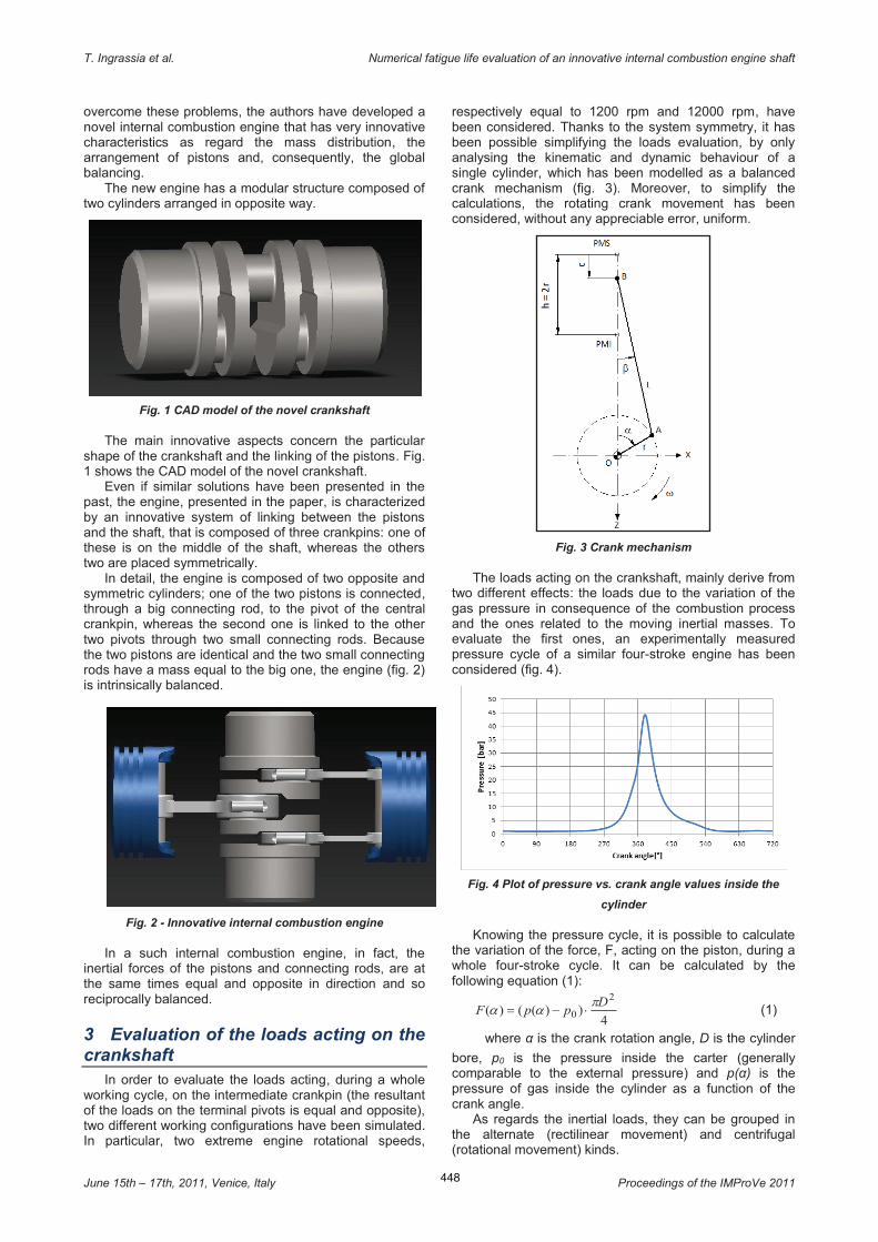
respectively equal to 1200 rpm and 12000 rpm, have been considered. Thanks to the system symmetry, it has been possible simplifying the loads evaluation, by only analysing the kinematic and dynamic behaviour of a single cylinder, which has been modelled as a balanced crank mechanism (fig. 3). Moreover, to simplify the calculations, the rotating crank movement has been considered, without any appreciable error, uniform.
Fig. 3 Crank mechanism
The loads acting on the crankshaft, mainly derive from two different effects: the loads due to the variation of the gas pressure in consequence of the combustion process and the ones related to the moving inertial masses. To evaluate the first ones, an experimentally measured pressure cycle of a similar four-stroke engine has been considered (fig. 4).
Fig. 4 Plot of pressure vs. crank angle values inside the
cylinder
Knowing the pressure cycle, it is possible to calculate the variation of the force, F, acting on the piston, during a whole four-stroke cycle. It can be calculated by the following equation (1):
4))(()(
2
0D
ppFp
aa ×-= (1)
where α is the crank rotation angle, D is the cylinder
bore, p0 is the pressure inside the carter (generally comparable to the external pressure) and p(α) is the pressure of gas inside the cylinder as a function of the crank angle.
As regards the inertial loads, they can be grouped in the alternate (rectilinear movement) and centrifugal (rotational movement) kinds.
449
T. Ingrassia et al. Numerical fatigue life evaluation of an innovative internal combustion engine shaft
June 15th – 17th, 2011, Venice, Italy Proceedings of the IMProVe 2011
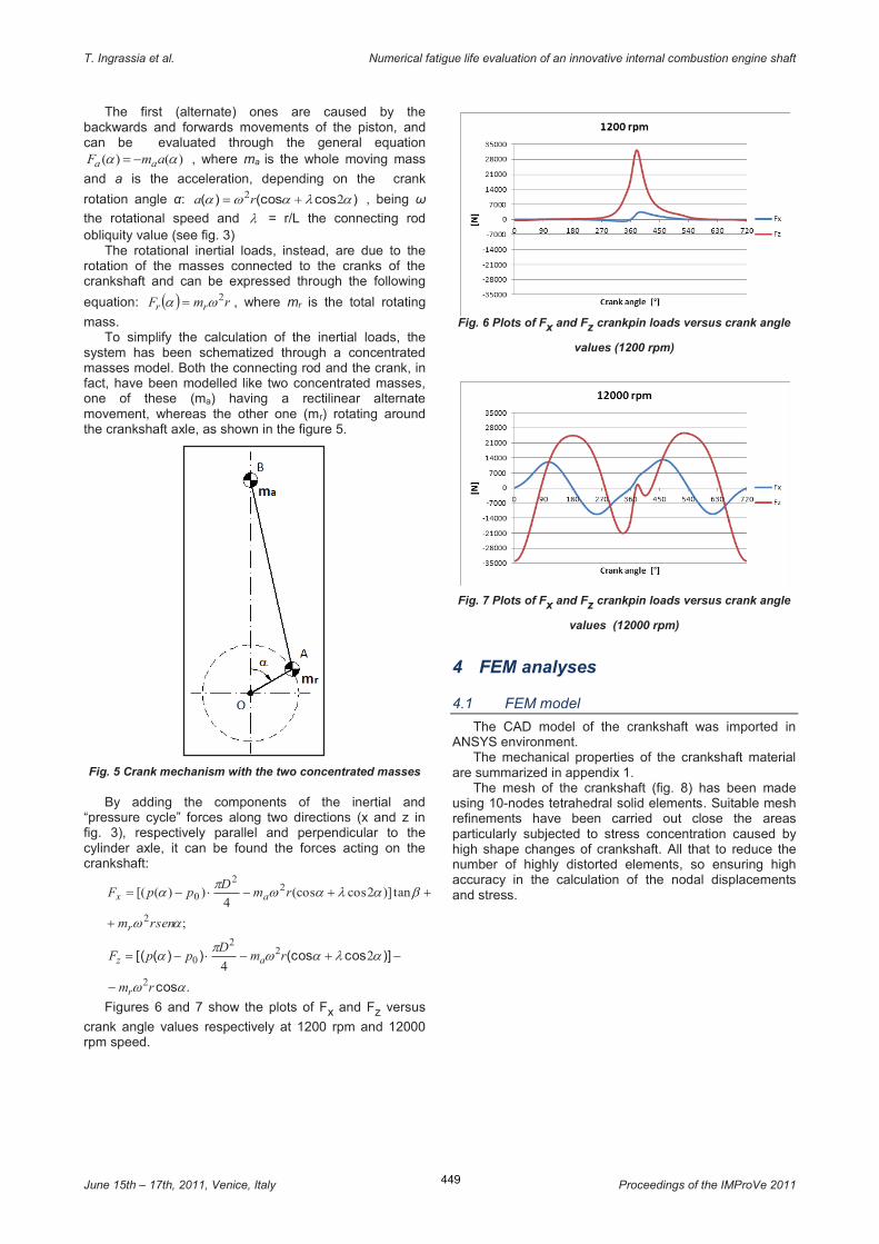
The first (alternate) ones are caused by the backwards and forwards movements of the piston, and can be evaluated through the general equation
)()( aa amF aa -= , where ma is the whole moving mass
and a is the acceleration, depending on the crank
rotation angle α: )cos(cos)( alawa 22 += ra , being ω
the rotational speed and l = r/L the connecting rod obliquity value (see fig. 3)
The rotational inertial loads, instead, are due to the rotation of the masses connected to the cranks of the crankshaft and can be expressed through the following
equation: ( ) rmF rr2wa = , where mr is the total rotating
mass. To simplify the calculation of the inertial loads, the
system has been schematized through a concentrated masses model. Both the connecting rod and the crank, in fact, have been modelled like two concentrated masses, one of these (ma) having a rectilinear alternate movement, whereas the other one (mr) rotating around the crankshaft axle, as shown in the figure 5.
Fig. 5 Crank mechanism with the two concentrated masses
By adding the components of the inertial and “pressure cycle” forces along two directions (x and z in fig. 3), respectively parallel and perpendicular to the cylinder axle, it can be found the forces acting on the crankshaft:
;
tan)]2cos(cos4
))([(
2
22
0
aw
balawp
a
rsenm
rmD
ppF
r
ax
+
++-×-=
.cos
)]cos(cos))([(
aw
alawp
a
rm
rmD
ppF
r
az
2
22
0 24
-
-+-×-=
Figures 6 and 7 show the plots of Fx and Fz versus
crank angle values respectively at 1200 rpm and 12000 rpm speed.
Fig. 6 Plots of Fx and Fz crankpin loads versus crank angle
values (1200 rpm)
Fig. 7 Plots of Fx and Fz crankpin loads versus crank angle
values (12000 rpm)
4 FEM analyses
4.1 FEM model
The CAD model of the crankshaft was imported in ANSYS environment.
The mechanical properties of the crankshaft material are summarized in appendix 1.
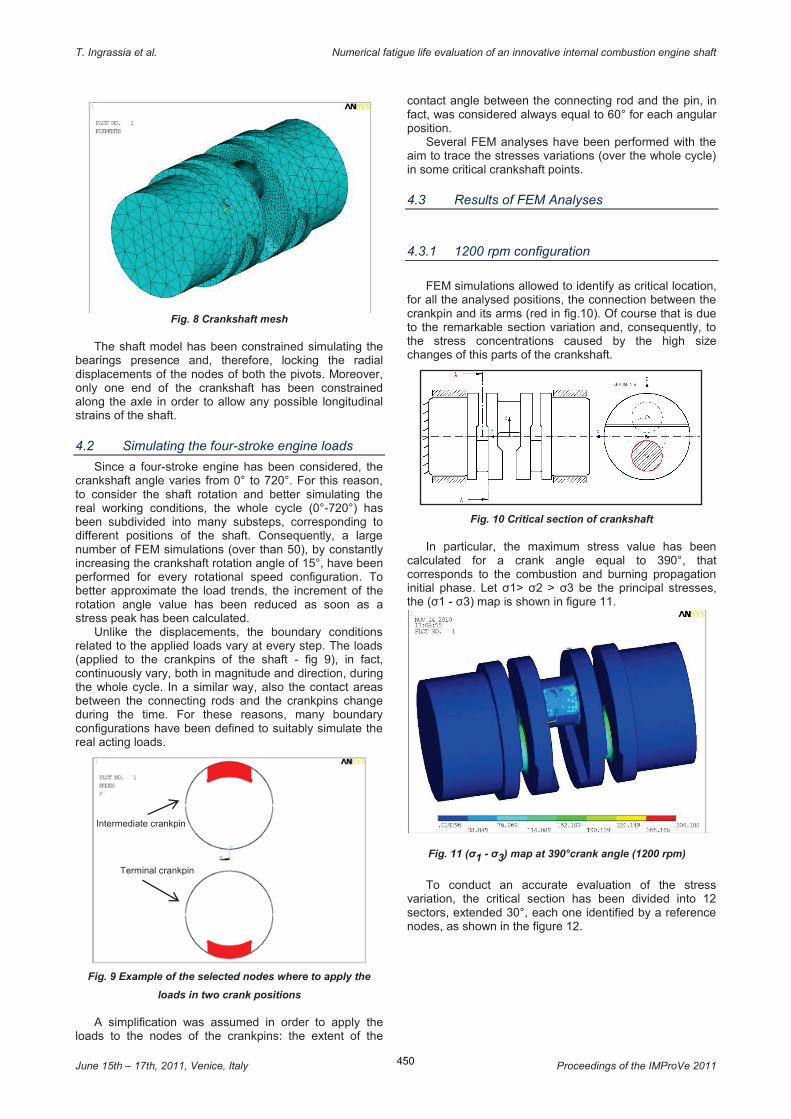
The mesh of the crankshaft (fig. 8) has been made using 10-nodes tetrahedral solid elements. Suitable mesh refinements have been carried out close the areas particularly subjected to stress concentration caused by high shape changes of crankshaft. All that to reduce the number of highly distorted elements, so ensuring high accuracy in the calculation of the nodal displacements and stress.
450
T. Ingrassia et al. Numerical fatigue life evaluation of an innovative internal combustion engine shaft
June 15th – 17th, 2011, Venice, Italy Proceedings of the IMProVe 2011
Fig. 8 Crankshaft mesh
The shaft model has been constrained simulating the bearings presence and, therefore, locking the radial displacements of the nodes of both the pivots. Moreover, only one end of the crankshaft has been constrained along the axle in order to allow any possible longitudinal strains of the shaft.
4.2 Simulating the four-stroke engine loads
Since a four-stroke engine has been considered, the crankshaft angle varies from 0° to 720°. For this reason, to consider the shaft rotation and better simulating the real working conditions, the whole cycle (0°-720°) has been subdivided into many substeps, corresponding to different positions of the shaft. Consequently, a large number of FEM simulations (over than 50), by constantly increasing the crankshaft rotation angle of 15°, have been performed for every rotational speed configuration. To better approximate the load trends, the increment of the rotation angle value has been reduced as soon as a stress peak has been calculated.
Unlike the displacements, the boundary conditions related to the applied loads vary at every step. The loads (applied to the crankpins of the shaft - fig 9), in fact, continuously vary, both in magnitude and direction, during the whole cycle. In a similar way, also the contact areas between the connecting rods and the crankpins change during the time. For these reasons, many boundary configurations have been defined to suitably simulate the real acting loads.
Fig. 9 Example of the selected nodes where to apply the
loads in two crank positions
A simplification was assumed in order to apply the loads to the nodes of the crankpins: the extent of the
contact angle between the connecting rod and the pin, in fact, was considered always equal to 60° for each angular position.
Several FEM analyses have been performed with the aim to trace the stresses variations (over the whole cycle) in some critical crankshaft points.
4.3 Results of FEM Analyses
4.3.1 1200 rpm configuration
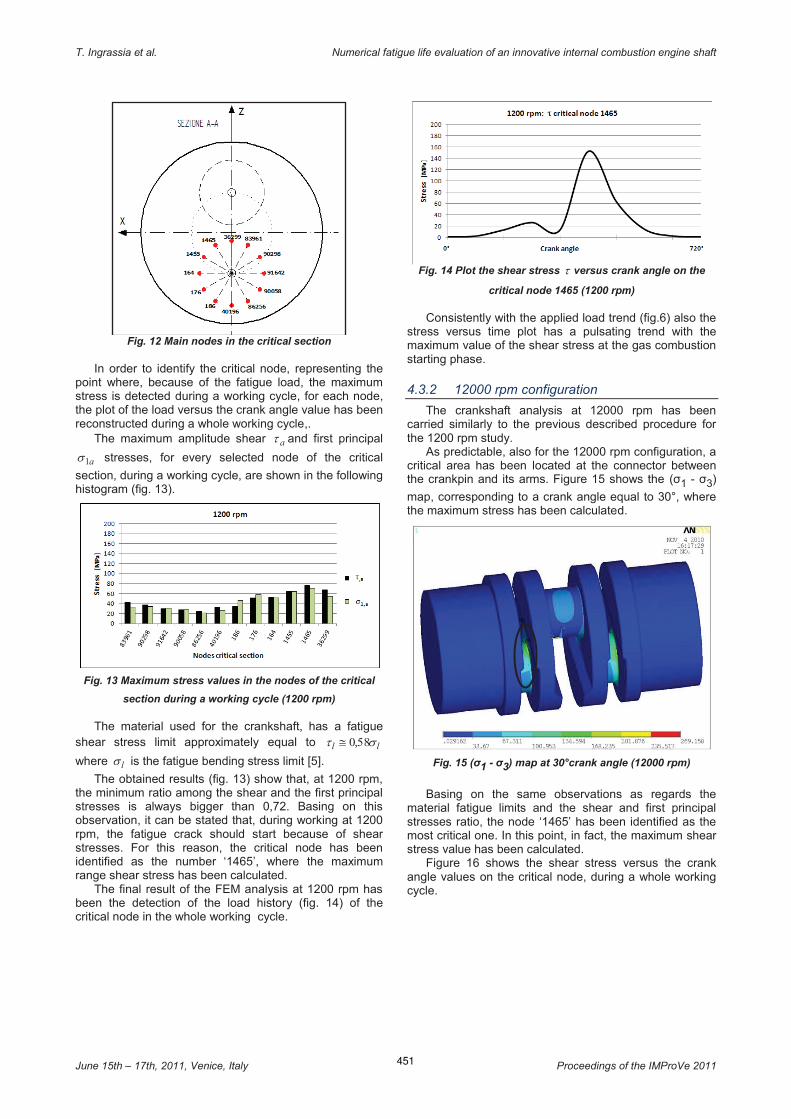
FEM simulations allowed to identify as critical location,
for all the analysed positions, the connection between the crankpin and its arms (red in fig.10). Of course that is due to the remarkable section variation and, consequently, to the stress concentrations caused by the high size changes of this parts of the crankshaft.
Fig. 10 Critical section of crankshaft
In particular, the maximum stress value has been calculated for a crank angle equal to 390°, that corresponds to the combustion and burning propagation initial phase. Let σ1> σ2 > σ3 be the principal stresses, the (σ1 - σ3) map is shown in figure 11.
Fig. 11 (σ1 - σ3) map at 390°crank angle (1200 rpm)
To conduct an accurate evaluation of the stress variation, the critical section has been divided into 12 sectors, extended 30°, each one identified by a reference nodes, as shown in the figure 12.
Intermediate crankpin
Terminal crankpin
451
T. Ingrassia et al. Numerical fatigue life evaluation of an innovative internal combustion engine shaft
June 15th – 17th, 2011, Venice, Italy Proceedings of the IMProVe 2011
Fig. 12 Main nodes in the critical section
In order to identify the critical node, representing the point where, because of the fatigue load, the maximum stress is detected during a working cycle, for each node, the plot of the load versus the crank angle value has been reconstructed during a whole working cycle,.
The maximum amplitude shear at and first principal
a1s stresses, for every selected node of the critical
section, during a working cycle, are shown in the following histogram (fig. 13).
Fig. 13 Maximum stress values in the nodes of the critical
section during a working cycle (1200 rpm)
The material used for the crankshaft, has a fatigue shear stress limit approximately equal to ll st 580,@
where ls is the fatigue bending stress limit [5].
The obtained results (fig. 13) show that, at 1200 rpm, the minimum ratio among the shear and the first principal stresses is always bigger than 0,72. Basing on this observation, it can be stated that, during working at 1200 rpm, the fatigue crack should start because of shear stresses. For this reason, the critical node has been identified as the number ‘1465’, where the maximum range shear stress has been calculated.
The final result of the FEM analysis at 1200 rpm has been the detection of the load history (fig. 14) of the critical node in the whole working cycle.
Fig. 14 Plot the shear stress t versus crank angle on the
critical node 1465 (1200 rpm)
Consistently with the applied load trend (fig.6) also the stress versus time plot has a pulsating trend with the maximum value of the shear stress at the gas combustion starting phase.
4.3.2 12000 rpm configuration
The crankshaft analysis at 12000 rpm has been carried similarly to the previous described procedure for the 1200 rpm study.
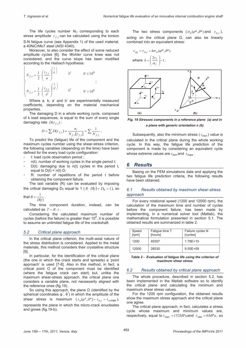
As predictable, also for the 12000 rpm configuration, a critical area has been located at the connector between the crankpin and its arms. Figure 15 shows the (σ1 - σ3)
map, corresponding to a crank angle equal to 30°, where the maximum stress has been calculated.
Fig. 15 (σ1 - σ3) map at 30°crank angle (12000 rpm)
Basing on the same observations as regards the material fatigue limits and the shear and first principal stresses ratio, the node ‘1465’ has been identified as the most critical one. In this point, in fact, the maximum shear stress value has been calculated.
Figure 16 shows the shear stress versus the crank angle values on the critical node, during a whole working cycle.

452
T. Ingrassia et al. Numerical fatigue life evaluation of an innovative internal combustion engine shaft
June 15th – 17th, 2011, Venice, Italy Proceedings of the IMProVe 2011
Fig. 16 Plot of the shear stresst versus crank angle on the
critical node 1465 (12000 rpm)
Due to the remarkable effect of the inertia actions, the loading cycle at 12000 rpm is much more complex than the 1200 rpm one.
5 Crankshaft fatigue life prediction To evaluate the fatigue life of the new crankshaft, two
different approaches have been used and compared: the maximum shear-stress approach and the critical plane one.
5.1 Maximum shear-stress approach
To apply the maximum shear-stress criterion, because of the not regular cycle of working load, both for the 1200 rpm and 12000 rpm configurations, the stress cycles (fig.14-16) have been convert to equivalent peaks and minima sequences. Moreover, these peaks and minima sequences have been reordered so that the starting points correspond to the minimum stress value of each cycle (fig. 17-18).
Fig. 17 Peaks-minima sequence at 1200 rpm
Because of its very simple nature, in the 1200 rpm analysis, the shear stress cycle (and consequently the peaks and minima sequence) has been reduced to an equivalent sinusoidal one, whose mean and alternate stress values are equal to:
MPama 762
max ===t
tt .
Fig. 18 Peaks-minima sequence at 12000 rpm
To evaluate the fatigue damaging in the 12000 rpm configuration, instead, different tools, like the rainflow counting method, the Goodman diagram and the Palmgren-Miner rule, have been used.
Using the rainflow method, the whole cycle has been subdivided in different reduced sequences and, for each one, the amplitude ia,t , the mean values im,t and the
repetitions number have been evaluated (table 1).
Rainflow-based cycle subdivision
Sequence ia,t im,t Repetitions ni
BC 13.3 32.7 n1=1
DE 21.5 64.5 n2=1
HI 13.5 67.9 n3=1
NO 10.8 50.8 n4=1
QR 18.6 36.2 n5=1
FG 42.5 59.6 n6=1
OP 43.4 60.9 n7=1
AL 62.8 72.2 n8=nk=1
Table 1 – Sequence, amplitude and mean stress value and repetitions number (12000 rpm)
To calculate the damaging rate )( ,ifD t due to every
sub cycle, instead of a couples ( ia,t , im,t ) of stresses, an
equivalent amplitude stress value has been calculated, by considering the effect of a mean stress value through the Haigh diagram (simplified Goodman model):
u
im
iaif
t
tt
t,
,,
-=
1
;
being iu,t the ultimate shear strength value.
So, knowing the equivalent amplitude value if ,t and
the repetitions number ni of every cycle (always equal to
1), the damaging rate, ][
)(,,
,ifif
iif
N
nD
tt = , can be
simplified in the following way:
ifif
ND
,, )(
1=t .
453
T. Ingrassia et al. Numerical fatigue life evaluation of an innovative internal combustion engine shaft
June 15th – 17th, 2011, Venice, Italy Proceedings of the IMProVe 2011
The life cycles number Nf,i corresponding to each stress amplitude if ,t can be calculated using the torsion
S-N fatigue curve (see Appendix 1) of the used material, a 40NiCrMo7 steel (AISI 4340).
Moreover, to also consider the effect of some reduced amplitude cycles [6], the Wohler curve knee was not considered, and the curve slope has been modified according to the Haibach hypothesis:
ïïï
î
ïïï
í
ì
÷÷ø
öççè
æ×=
÷÷ø
öççè
æ×=
÷ø
öçè
æ
÷ø
öçè
æ
',,
,,
'
bifif
bifif
a
tN
a
tN
1
1
2
1
2
1
if
if
6
6
10
10
>
£
N
N
;
Where a, b, a’ and b’ are experimentally measured coefficients, depending on the material mechanical properties.
The damaging D in a whole working cycle, composed of k load sequences, is equal to the sum of every single damaging rate )( ,ifD t :
åå ===ififif
iif
NN
nDD
,,,, ][
)(1
tt .
To predict the (fatigue) life of the component and the maximum cycles number using the shear-stress criterion, the following variables (depending on the time) have been defined for the every load cycle configuration: - t: load cycle observation period ; - n(t): number of working cycles in the single period t; - D(t): damaging due to n(t) cycles in the period t,
equal to D(t) = n(t) D; - R: number of repetitions of the period t before
obtaining the component failure. The last variable (R) can be evaluated by imposing
the critical damaging D0 equal to 1 ( ( ) 10 ==× DtDR ), so
that ( )tDR
1= .
The time component duration, instead, can be calculated as tRT ×= .
Considering the calculated maximum number of cycles (before the failure) is greater than 108, it is possible to assume an unlimited fatigue life of the crankshaft.
5.2 Critical plane approach
In the critical plane criterion, the multi-axial nature of the stress distribution is considered. Applied to the metal materials, this method considers their crystalline structure
[9]. In particular, for the identification of the critical plane
(the one in which the crack starts and spreads) a ‘point approach’ is used [7-8]. Also in this method, in fact, a critical point O of the component must be identified (where the fatigue crack can start) but, unlike the maximum shear-stress approach, the critical plane one considers a variable plane, not necessarily aligned with the reference ones (fig.19).
So using this approach, the plane Ω (identified by the spherical coordinates φ
*, θ
*) in which the amplitude of the shear stress is maximum ( max,,*)*,( ncnn ttJjt == ),
represents the plane in which the micro-crack enucleates and grows (fig.19-b).
The two stress components ( *)*,( Jjsn and cn,t ),
acting on the critical plane Ω, can also be linearly combined into an equivalent stress:
*)*,(, Jjstt ncneq k+=
where 12
-÷÷ø
öççè
æ=
l
lkst
.
Fig. 19 Stresses components in a reference plane (a) and in
a plane with generic orientation n (b)
Subsequently, also the minimum stress ( mint ) value is
calculated in the critical plane during the whole working cycle. In this way, the fatigue life prediction of the component is made by considering an equivalent cycle whose extreme values are mint and maxt .
6 Results Basing on the FEM simulations data and applying the
two fatigue life prediction criteria, the following results have been obtained.
6.1 Results obtained by maximum shear-stress approach
For every rotational speed (1200 and 12000 rpm), the calculation of the maximum time and number of cycles before the component failure, has been made by implementing, in a numerical solver tool (Matlab), the mathematical formulation presented in section 5.1. The obtained results are summarized in table 2.
Speed [rpm]
Fatigue time T [hours]
Failure cycles N [cycles]
1200 49357 1.78E+10
12000 26530 9.55E+09
Table 2 - Evaluation of fatigue life using the criterion of maximum shear stress
6.2 Results obtained by critical plane approach
The whole procedure, described in section 5.2, has been implemented in the Matlab software so to identify the critical plane and calculating the minimum and maximum shear stress values.
For the 1200 rpm configuration, the obtained results show the maximum stress approach and the critical plane one agree.
The critical plane approach, in fact, calculates a stress cycle whose maximum and minimum values are, respectively, equal to MPa152max =t and MPa0min =t , so
454
T. Ingrassia et al. Numerical fatigue life evaluation of an innovative internal combustion engine shaft
June 15th – 17th, 2011, Venice, Italy Proceedings of the IMProVe 2011
that MPama 762
minmax =-
==tt
tt , like previously
evaluated with the maximum shear stress method. At 12000 rpm, instead, the critical plane approach
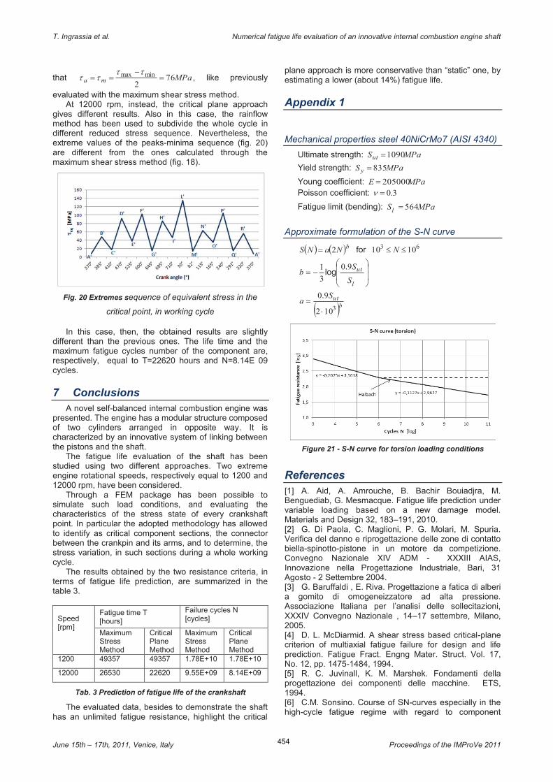
gives different results. Also in this case, the rainflow method has been used to subdivide the whole cycle in different reduced stress sequence. Nevertheless, the extreme values of the peaks-minima sequence (fig. 20) are different from the ones calculated through the maximum shear stress method (fig. 18).
Fig. 20 Extremes sequence of equivalent stress in the
critical point, in working cycle
In this case, then, the obtained results are slightly different than the previous ones. The life time and the maximum fatigue cycles number of the component are, respectively, equal to T=22620 hours and N=8.14E 09 cycles.
7 Conclusions A novel self-balanced internal combustion engine was
presented. The engine has a modular structure composed of two cylinders arranged in opposite way. It is characterized by an innovative system of linking between the pistons and the shaft.
The fatigue life evaluation of the shaft has been studied using two different approaches. Two extreme engine rotational speeds, respectively equal to 1200 and 12000 rpm, have been considered.
Through a FEM package has been possible to simulate such load conditions, and evaluating the characteristics of the stress state of every crankshaft point. In particular the adopted methodology has allowed to identify as critical component sections, the connector between the crankpin and its arms, and to determine, the stress variation, in such sections during a whole working cycle.
The results obtained by the two resistance criteria, in terms of fatigue life prediction, are summarized in the table 3.
Speed [rpm]
Fatigue time T [hours]
Failure cycles N [cycles]
Maximum Stress Method
Critical Plane Method
Maximum Stress Method
Critical Plane Method
1200 49357 49357 1.78E+10 1.78E+10
12000 26530 22620 9.55E+09 8.14E+09
Tab. 3 Prediction of fatigue life of the crankshaft
The evaluated data, besides to demonstrate the shaft has an unlimited fatigue resistance, highlight the critical
plane approach is more conservative than “static” one, by estimating a lower (about 14%) fatigue life.
Appendix 1
Mechanical properties steel 40NiCrMo7 (AISI 4340)
Ultimate strength: MPaSut 1090=
Yield strength: MPaS y 835=
Young coefficient: MPaE 205000= Poisson coefficient: 3.0=n
Fatigue limit (bending): MPaSl
564=
Approximate formulation of the S-N curve
( ) ( )bNaNS 2= for 63 1010 ££ N
÷÷
ø
ö
çç
è
æ-=
l
ut
S
Sb
90
3
1 .log
( )butS
a3102
90
×=
.
Figure 21 - S-N curve for torsion loading conditions
References [1] A. Aid, A. Amrouche, B. Bachir Bouiadjra, M. Benguediab, G. Mesmacque. Fatigue life prediction under variable loading based on a new damage model. Materials and Design 32, 183–191, 2010. [2] G. Di Paola, C. Maglioni, P. G. Molari, M. Spuria. Verifica del danno e riprogettazione delle zone di contatto biella-spinotto-pistone in un motore da competizione. Convegno Nazionale XIV ADM - XXXIII AIAS, Innovazione nella Progettazione Industriale, Bari, 31 Agosto - 2 Settembre 2004. [3] G. Baruffaldi , E. Riva. Progettazione a fatica di alberi a gomito di omogeneizzatore ad alta pressione. Associazione Italiana per l’analisi delle sollecitazioni, XXXIV Convegno Nazionale , 14–17 settembre, Milano, 2005. [4] D. L. McDiarmid. A shear stress based critical-plane criterion of multiaxial fatigue failure for design and life prediction. Fatigue Fract. Engng Mater. Struct. Vol. 17, No. 12, pp. 1475-1484, 1994. [5] R. C. Juvinall, K. M. Marshek. Fondamenti della progettazione dei componenti delle macchine. ETS, 1994. [6] C.M. Sonsino. Course of SN-curves especially in the high-cycle fatigue regime with regard to component

455
T. Ingrassia et al. Numerical fatigue life evaluation of an innovative internal combustion engine shaft
June 15th – 17th, 2011, Venice, Italy Proceedings of the IMProVe 2011
design and safety. International Journal of Fatigue 29, 2246–2258, 2007. [7] I. V. Papadopoulos. Long life fatigue under multiaxial loading. International Journal of Fatigue 23, 839–849, 2001. [8] I. V. Papadopoulos. Critical plane approaches in high-cycle fatigue: on the definition of the amplitude and mean value of the shear stress acting on the critical plane. Fatigue & Fracture of Engineering Materials & Structures, 21: 269–285, 1998. [9] I. V. Papadopoulos. A high-cycle fatigue criterion applied in biaxial and triaxial out-of-phase stress conditions. Fatigue Fract. Engng Mater. Struct. Vol. 18, No. 1, pp. 79-91, 1995. [10] J. E. Shigley, C. R. Miscke, R. G. Budynas. Progetto e costruzione di macchine; capitolo 7, McGraw-Hill – Milano, 2005.