Embed Size (px)
Citation preview
THE PUBLISHING HOUSE PROCEEDINGS OF THE ROMANIAN ACADEMY, Series A, OF THE ROMANIAN ACADEMY Volume 18, Number 1/2017, pp. 64–71
NUMERICAL AND EXPERIMENTAL INVESTIGATIONS OF THE FLOW CONFIGURATION IN VICINITY OF IMMERSED SMOOTH AND PATTERNED
CYLINDERS
Nicoleta Octavia TĂNASE, Diana BROBOANĂ, Corneliu BĂLAN
“Politehnica” University of Bucharest, Reorom Laboratory, Hydraulic Departament, Romania Corresponding author: Nicoleta Octavia TĂNASE, E-mail: [email protected]
Abstract. The paper is concerned with the CFD analysis of the 2D free surface flows in the vicinity of smooth and patterned immersed cylinders. The main goal of the study is to evaluate and to quantify the influence of the grooved surfaces of the immersed cylinders on the local hydrodynamics and wake configuration. The investigated motion is weakly turbulent in the sub-critical regime. The numerics are performed with the Fluent code using the RNG k-ε turbulence model coupled with VOF for the computation of the free surface. The results indicate that presence of a grooved geometry with small aspect ratio on the surface of the immersed cylinders changes the flow spectrum downstream the bodies, especially in the structure of the separated shear-layers which delimit the wake. These qualitative modifications of the flow spectrum are confirmed by the decreasing of the viscous forces due to the presence of the grooves on the cylinder surface. The present experimental and CFD study emphasis value and novel information on the changes in the local hydrodynamics of immersed bodies induced by the patterned surfaces. The authors propose the spectrum of vorticity number as complementary kinematics criteria to evaluate and characterize the shear layer and wake configurations downstream the immersed bodies.
Key words: free surface flow, immersed cylinder, grooved wall, separation point, vorticity number.
1. INTRODUCTION
The free surface flows around immersed bodies, in particular flows around immersed cylinders in presence of water-air interface, is a constant topic of investigation in literature for the last two decades. Despite the numerous existing CFD applications in hydrology, hydraulics and hydraulic turbines, marine platforms, inflatable dams, this particular flow is still of interest for fundamental research in fluid mechanics, in relation to hydraulics jump, boundary layer theory, flow instabilities and transition to turbulence. The motion is characterized by two non-dimensional parameters: the Reynolds number and the Froude number,
0
0
Re V Dρ=η
, 0Fr Vg D
= , (1)
where V0 is the average velocity upstream the cylinder, D is the diameter of the cylinder, ρ is the density,
0η is the viscosity and g is the gravitational acceleration [16, 18, 19]. The previous studies dedicated to this subject were mainly focused to evaluate the influence of the
Froude number on the flow pattern, respectively to determine the influence of the immersed depth on the downstream vortical structures and wake, the stability of shear-layers and the mechanism of the vorticity transfer from the free surface to the wake. Sheridan et al. [15] remarked in the first detailed experimental study that presence of the free surface damps the Kármán vortex-type instability downstream the immersed cylinder, but maintain relatively stable the Kelvin-Helmholtz vortices-type instability associated with the shear-layer which bound the wake.
The works dedicated to the flow characterization and modeling around immersed bodies with patterned surface are only recently published in the literature. The effect of the grooved surface of the cylinder on the drag and the differences against the smooth geometry were experimentally and numerically investigated by
2 Flow configuration in vicinity of immersed smooth and patterned cylinders 65
Yamagishi and Oki [21]. This flow configuration is of great interest for various applications, especially in relation to the drag dependence on the Reynolds number for the grooved (cactus-shape) cylinders. The phenomena of the drag decreasing induced by the grooves of the immersed bodies were later investigated by other authors, e.g. [1, 3, 6, 11]. The effect of cactus-like spines on the topology and the dynamics of the flow past a stationary or pivoted cylinder were studied by Levy and Liu [9]. The experiments were performed either in a water channel or in a wind tunnel at low to moderate Reynolds numbers. The spines around the cylinders tend to slow down the flow, enlarging the recirculation region in length and width, which causes a local increase of the pressure in the near wake.
A recent numeric study of the flow structure around a circular cylinder with V-grooves was made by Munendra et al. [12]. The V-grooves drop the drag coefficient in comparison to a smooth similar cylinder by almost 30% and also reduce the vortex region behind the obstacle.
Wang et al. [20] have examined the influence of the cactus-analogue grooved surface on the fluid flow, with particular emphasis on the wall-pressure fluctuations and the near-cylinder hydrodynamics. The study confirms some important findings of the previous studies, e.g. [6], on the flow around grooved immersed cylinder in comparison with the smooth geometry: (i) reduction of the drag due to recirculation in the grooves, and delay of the separation layer from the immersed grooved body, (ii) wall pressure fluctuations are damped by the grooves and vortical structures close to the grooved surface are more organized.
The experimental and numerical analyses of the flow around immersed bodies are also presented in some previous papers of the authors [17–19], where the studies were mainly focused to the measurements and computations of the free surface. In the most recent paper dedicated to the modeling of the flow over an immersed broad-crested weir, the work emphasized the influence of patterned surfaces of the broad-crested weir on the free surface profile [17].
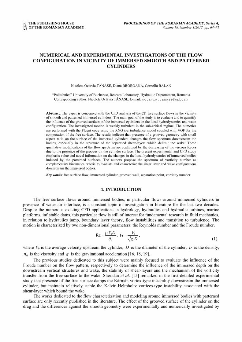
In present investigations the qualitative direct visualizations of the flow spectrum were obtained for the flow regime characterized by the Reynolds number Re = 7 500 and Froude number Fr = 0.214.
The experiments are performed in a free surface transparent water channel whose cross-section is a rectangular with maximum height Hmax = 150 mm and width B = 15 mm. The cylinder with the diameter D = 50 mm is located at the distance L1 = 303 mm from the entrance section (Fig. 1). The entrance depth H0 = 105 mm and the height of the weir hw = 64 mm were maintained constant during the experiments. The images were recorded with a Sony SLT digital camera at a frequency of 12 frames/s (for details see [16, 19]).
Fig. 1 – Flow domain and the geometry of the experimental channel of 15 mm width and cylinder diameter of D = 50 mm.
The 2D flow spectrum, the separation points on the immersed cylinder (D1 and D2) and the wake downstream are represented [19].
The main goal of the paper is to investigate the influence of the grooved surfaces of the immersed cylinder on the local hydrodynamics and wake configuration. The study is based on the corroboration between experiments and numerical simulations performed with the Fluent code (RNG k-ε turbulence model coupled with VOF). The investigations are concerned with the following aspects: (i) the location of the separation points on smooth and patterned cylinders, (ii) the flow spectrum of the wake downstream the cylinders, (iii) the distributions of the shear stress, vorticity and the turbulence intensity around the cylinders. The tested geometries under investigation are smooth and patterned cylinders with small aspect ratio between the groove height δ and the cylinder diameter 02.0: <= Dδδ . The cylinders are immersed in the free surface water channel (Fig. 1); the bodies are placed in the vicinity of the free surface and the flow is considered to be pseudo-planar and steady.
Nicoleta Octavia TĂNASE, Diana BROBOANĂ, Corneliu BĂLAN 3 66
The experimental visualizations and measurements were focused to the region between the free surface and the wake downstream the cylinder. The positions of the upper and lower separation points of the boundary layer from the cylinders and the wake trace were the main experimental characteristics compared with the numerical results.
The paper is structured in 4 paragraphs. Following the Introduction, paragraph 2 is concerned with the numerical procedure of the flow around a smooth cylinder. The paragraph 3 is dedicated to the comparison between the hydrodynamics in the vicinity of smooth and patterned cylinders. Two type of patterns on the surface of cylinders are studied: round and square teeth-grooves with small aspect ratio. The numerical results for vorticity, turbulent intensity, shear stresses and vorticity number distributions in vicinity of immersed cylinder are shown.
The final remarks and conclusions are given in paragraph 4. This section includes a brief analyze of the computed drag forces and coefficients, and also the further direction of the study. The paper ends with acknowledgement and the list of references.
2. NUMERICAL SIMULATIONS OF THE FLOW AROUND IMMERSED CYLINDER
In previous papers the authors established the RNG k-ε turbulence model (coupled with the VOF code) as the most indicated numerical procedure to reproduce qualitatively and quantitatively the experiments performed in the planar free surface flow around the immersed smooth cylinder [16, 18, 19], for details on the PIV technique used in our experiments see [10, 13, 15, 16].
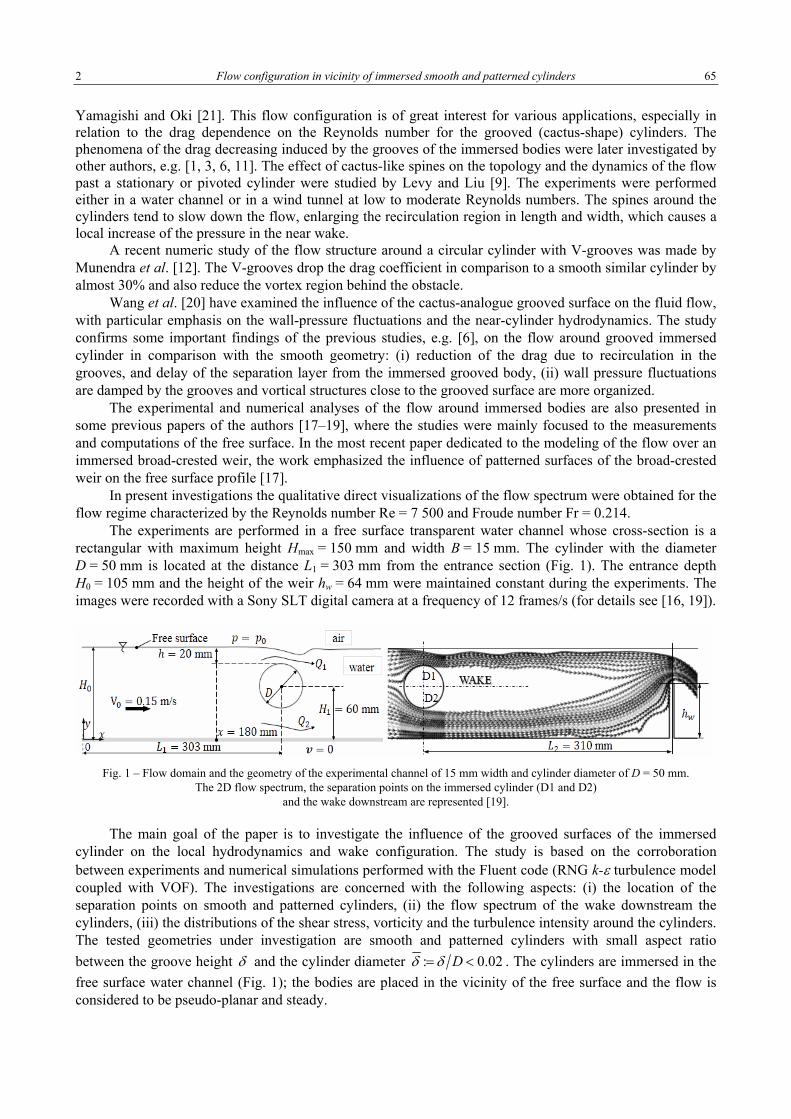
The working geometry is the 2D configuration from Fig. 1, see also [18, 19]. The mesh for the whole domain (water and air) has 638.436 cells (quad-element, type map and tri-elements, pave type), 1.270.606 faces and 632.170 nodes. The geometry and mesh were built using the pre-processor Gambit. The mesh is structured around the cylinder and the corresponding values of dimensionless wall distance +y are in the recommended range of 70 <+< y . The quality of the mesh plays a significant role in the accuracy and stability of the numerical computation. One important indicator of the mesh quality is a parameter referred as the orthogonal quality: the worst cells will have an orthogonal quality closer to 0 and the best cells will have an orthogonal quality closer to 1, [2]. In our case the value is 0.7. Another parameter of the mesh quality is the distribution of the cell equiangle skew, the acceptable quality being in this case represented by values lower than 0.5. One concludes that the constructed mesh is proper for the numerical analysis of the flow under investigation.
The boundary conditions (Fig. 1) for the numerical simulations are: (i) entrance water ( 0=x ): the height 1050 =H mm is kept constant, imposing the linear relative pressure distribution ygp ⋅⋅= ρ ,
00 Hy ≤≤ ; (ii) the entrance of the air, top-air and exit: constant atmospheric pressure, 0pp = ; (iii) adherence (no slip) conditions at solid walls: velocity 0=v [18, 19].
The solvers are run under steady conditions and no influence of surface tension on the free surface line was taken into consideration. The computations are performed on a 64-bit server Dual 2.33 GHz with 16 GB RAM memory, the computation time for each case being around 4 days at a precision of 10-5.
Fig. 2 – The local geometry a) and the mesh for smooth (638 436 cells, 1 270 606 faces, 632 170 nodes); b) and grooved; c) cylinders; two patterned geometries are used in the study P1 (690 012 cells, 1 386 166 faces, 696 154 nodes),
respectively P2 (718 729 cells, 1 444 709 faces, 725 980 nodes).
DETAIL
a) b) c)
4 Flow configuration in vicinity of immersed smooth and patterned cylinders 67
The numerical simulations of the free surface flow around cylinders with grooved surfaces was performed in 2D configuration using the same turbulence model and the same boundary conditions as for the smooth cylinder. The working geometries (smooth, patterned P1 and patterned P2), with details on the mesh and the number of the elements, are shown in the Fig. 2.
3. COMPARISON BETWEEN SMOOTH AND PATTERNED IMMERSED CYLINDERS
A cylinder with grooved surface (the patterned cylinder P1) was investigated experimentally under the same conditions as the smooth cylinder. The groove have a round tooth geometry with small aspect ratio
014.0: == Dδδ ; the grooves are dense uniformly distributed on the cylinder of nominal diameter
502 0 =R mm. A similar aspect ratio characterize the patterned cylinder P2, where the grooves are square teeth, Fig. 2a. We have to mention that hydrodynamics around the immersed cylinder P2 was investigated only numerically.
The main kinematic quantities used to analyze and interpret the distribution of vortical structures around immersed bodies in 2D simulations are the magnitude of vorticity [5, 7],
curl=ω v (2)
and the turbulent intensity I on the main flow direction,
Vv′
=I (3)
where V is the average flow velocity, v′ is the root-mean-square of the turbulent velocity fluctuations [2, 8]. A possible quantification of the vortical structures is the vorticity number, Wo, defined as the ratio
between the vorticity magnitude and the local the local strain rate γ [4],
Wo = ωγ
. (4)
The flow domains with Wo > 1 are regions where vortices might be present. However, since at separation points the wall shear stress is zero, i.e. the strain rate and vorticity are simultaneously zero, it is expected to find a discontinuity in the computed vorticity number in vicinity of that points.
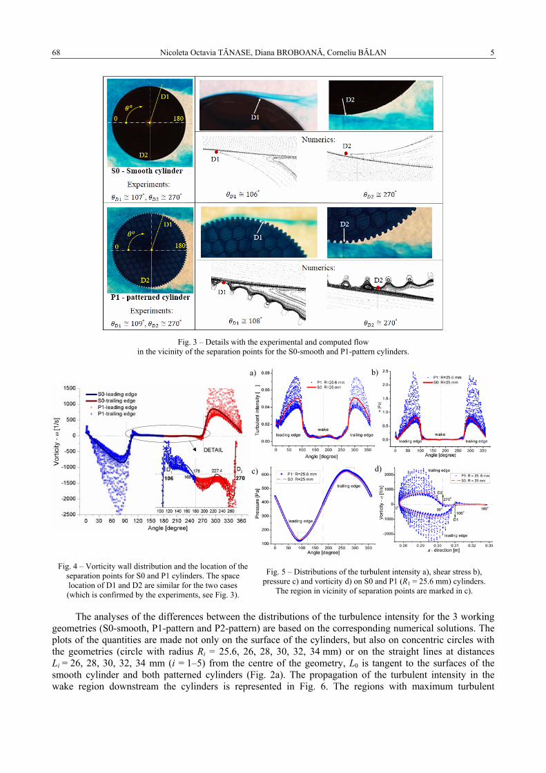
The values and distributions of vorticity number can be associated with the vorticity flux [14]. Maximum vorticity number corresponds to maximum local rotation of particles, which are expected to take place in the neighborhood of the wake boundary, starting from the separation point downstream the immersed cylinder. The flow in vicinity of the separations points D1 and D2 for the smooth and P1 cylinders are shown in Fig. 3 and the vorticity distributions on the walls are represented in Fig. 4.
In Fig. 5 are plotted representative quantities computed on the wall of S0 smooth cylinder and on the circle tangent to P1 geometry (R1 = 25.6 mm, see Fig. 2a). The differences are remarkable in the local magnitudes of shear stress, σ and turbulent intensity, ,I not in the pressure distributions. The micro-
patterns induce high space fluctuations of vorticity (respectively I and σ ) at the wall and in the very vicinity of the patterned cylinder, but also decrease the wall values in majority of the points (Fig. 4).
Nicoleta Octavia TĂNASE, Diana BROBOANĂ, Corneliu BĂLAN 5 68
Fig. 3 – Details with the experimental and computed flow
in the vicinity of the separation points for the S0-smooth and P1-pattern cylinders.
Fig. 4 – Vorticity wall distribution and the location of the separation points for S0 and P1 cylinders. The space location of D1 and D2 are similar for the two cases (which is confirmed by the experiments, see Fig. 3).
Fig. 5 – Distributions of the turbulent intensity a), shear stress b), pressure c) and vorticity d) on S0 and P1 (R1 = 25.6 mm) cylinders.
The region in vicinity of separation points are marked in c).
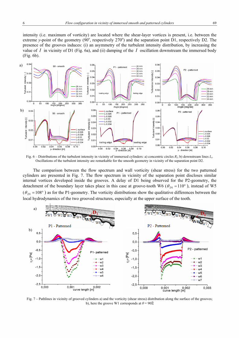
The analyses of the differences between the distributions of the turbulence intensity for the 3 working geometries (S0-smooth, P1-pattern and P2-pattern) are based on the corresponding numerical solutions. The plots of the quantities are made not only on the surface of the cylinders, but also on concentric circles with the geometries (circle with radius Ri = 25.6, 26, 28, 30, 32, 34 mm) or on the straight lines at distances Li = 26, 28, 30, 32, 34 mm (i = 1–5) from the centre of the geometry, L0 is tangent to the surfaces of the smooth cylinder and both patterned cylinders (Fig. 2a). The propagation of the turbulent intensity in the wake region downstream the cylinders is represented in Fig. 6. The regions with maximum turbulent
a) b)
c) d)
6 Flow configuration in vicinity of immersed smooth and patterned cylinders 69
intensity (i.e. maximum of vorticity) are located where the shear-layer vortices is present, i.e. between the extreme y-point of the geometry (90o, respectively 270o) and the separation point D1, respectively D2. The presence of the grooves induces: (i) an asymmetry of the turbulent intensity distribution, by increasing the value of I in vicinity of D1 (Fig. 6a), and (ii) damping of the I oscillation downstream the immersed body (Fig. 6b).
Fig. 6 – Distributions of the turbulent intensity in vicinity of immersed cylinders: a) concentric circles Ri; b) downstream lines Li.
Oscillations of the turbulent intensity are remarkable for the smooth geometry in vicinity of the separation point D2.
The comparison between the flow spectrum and wall vorticity (shear stress) for the two patterned cylinders are presented in Fig. 7. The flow spectrum in vicinity of the separation point discloses similar internal vortices developed inside the grooves. A delay of D1 being observed for the P2-geometry, the detachment of the boundary layer takes place in this case at groove-tooth W6 ( °= 1101Dθ ), instead of W5 ( °= 1081Dθ ) as for the P1-geometry. The vorticity distributions show the qualitative differences between the local hydrodynamics of the two grooved structures, especially at the upper surface of the tooth.
Fig. 7 – Pathlines in vicinity of grooved cylinders a) and the vorticity (shear stress) distribution along the surface of the grooves;
b), here the groove W1 corresponds at θ = 90º.
a)
b)
a)
b)
Nicoleta Octavia TĂNASE, Diana BROBOANĂ, Corneliu BĂLAN 7 70
4. FINAL REMARKS AND CONCLUSIONS
The influence of the patterned surfaces on the local hydrodynamics of immersed bodies is a subject of interest not only for applied fluid mechanics and hydraulics, but also for the fundamental research dedicated to the hydrodynamics instability and transition to turbulence.
The present work investigated the flow in the vicinity of the separation points for smooth and grooved of pattern surfaces of an immersed cylinder, under weakly turbulent sub-critical conditions. The analyse was focused to put in evidence the differences between a smooth and two grooved immersed cylinders. The peak in turbulent intensity in the vicinity of the separation point D1 (Fig. 6a) are found to be with more 25% higher for the patterned geometries in comparison with the smooth one. The influence of the grooved surfaces are also remarkable in the region of the trailing edge, close to the separation point D2, where their presence damp the oscillations of the vorticity and turbulence intensity downstream the cylinder (Fig. 6b).
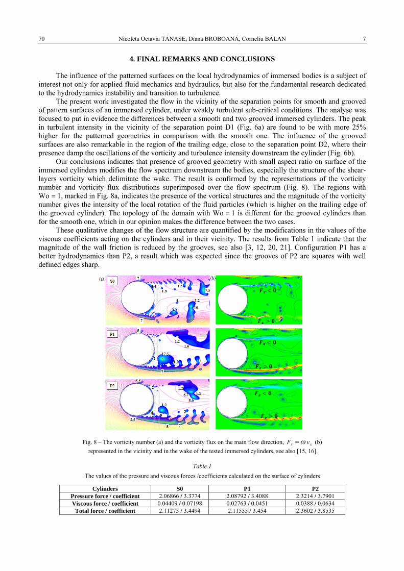
Our conclusions indicates that presence of grooved geometry with small aspect ratio on surface of the immersed cylinders modifies the flow spectrum downstream the bodies, especially the structure of the shear-layers vorticity which delimitate the wake. The result is confirmed by the representations of the vorticity number and vorticity flux distributions superimposed over the flow spectrum (Fig. 8). The regions with Wo > 1, marked in Fig. 8a, indicates the presence of the vortical structures and the magnitude of the vorticity number gives the intensity of the local rotation of the fluid particles (which is higher on the trailing edge of the grooved cylinder). The topology of the domain with Wo > 1 is different for the grooved cylinders than for the smooth one, which in our opinion makes the difference between the two cases.
These qualitative changes of the flow structure are quantified by the modifications in the values of the viscous coefficients acting on the cylinders and in their vicinity. The results from Table 1 indicate that the magnitude of the wall friction is reduced by the grooves, see also [3, 12, 20, 21]. Configuration P1 has a better hydrodynamics than P2, a result which was expected since the grooves of P2 are squares with well defined edges sharp.
Fig. 8 – The vorticity number (a) and the vorticity flux on the main flow direction, xx vF ω= (b)
represented in the vicinity and in the wake of the tested immersed cylinders, see also [15, 16].
Table 1 The values of the pressure and viscous forces /coefficients calculated on the surface of cylinders
Cylinders S0 P1 P2 Pressure force / coefficient 2.06866 / 3.3774 2.08792 / 3.4088 2.3214 / 3.7901 Viscous force / coefficient 0.04409 / 0.07198 0.02763 / 0.0451 0.0388 / 0.0634
Total force / coefficient 2.11275 / 3.4494 2.11555 / 3.454 2.3602 / 3.8535
8 Flow configuration in vicinity of immersed smooth and patterned cylinders 71
The analysed flow configuration is not symmetric and the grooves have a different geometry and aspect ratio than the most used in the previous published papers. So, the present experimental and CFD investigations emphasis value and novel information on the changes in the local hydrodynamics of immersed bodies induced by the patterned surface. Based on the numerical simulations, the author propose a complementary kinematics criteria to evaluate the flow configuration: the vorticity spectrum associated with the wake configuration (Fig. 8).
The results of the paper also enlarged the perspective for the further studies in the domain of free surface flows around immersed bodies. One such direction of interest for our group is to investigate for the immersed cylinder with micro-grooves surfaces the influence of the fluid elasticity on the wake and shear-layers configurations.
ACKNOWLEDGMENTS
The authors acknowledge the financial support received from the grant of the Romanian National Authority for Scientific Research, CNDI-UEFISCDI, project number PN-II-PT-PCCA-2011-3.1-0052 and grant of the Ministry of National Education, CNCS – UEFISCDI, project number PN-II-ID-PCE-2012-4-0245. Nicoleta Octavia Tanase acknowledges the financial contribution from the postdoctoral project InnoRESEARCH - POSDRU/159/1.5/S/132395.
REFERENCES
1. ABBOUD J.E., KARAKI W.S., OWEIS G.F., Particle image velocimetry measurements in the wake of a cactus-shaped cylinder, J. Fluids Eng, 133, 9, pp. 1–3, 2011.
2. ANSYS INC., Ansys Fluent Theory Guide, 2013. 3. BABU P., MAHESH K., Aerodynamic loads on cactus-shaped cylinders at low Reynolds numbers, Phys Fluids, 20, pp. 1–9.
2008. 4. BALAN C., BROBOANA D., KÁDÁR R., Vortex and vorticity. Vortex dominated flows and applications, edit. by Susan-
Resiga R. et al., Eurostampa, Timişoara, 2007, pp. 430–442. 5. DANAILA S., BERBENTE C., Numerical methods in fluid dynamics (in Romanian), Edit. Academiei, Bucuresti; 2003. 6. EL-MAKDAH A.M., OWEIS G.F., The flow past a cactus-inspired grooved cylinder, Exp. Fluids, 54, pp. 1–16, 2013. 7. FERZIGER J.H., PERIC M., Computational methods for fluid dynamics, Springer, Berlin, 1999. 8. LAUNDER B.E., SPALDING D.B., Mathematical models of turbulence, Academic Press, London, 1972. 9. LEVY B., LIU Y., The effects of cactus inspired spines on the aerodynamics of a cylinder, J. Fluids Struct, 39, pp. 335–346, 2013. 10. LIN J., PHETKONG N., SHERIDAN J., ROCKWELL D., Controlled motion of a cylinder through a free surface: Effect of
depth of penetration, J. Fluids Struct., 10, 4, pp. 309–317, 1996. 11. Liu Y.Z., Shi L.L., Yu J., TR-PIV measurement of the wake behind a grooved cylinder at low Reynolds number, J. Fluids
Struct., 27, 3, pp. 394–407, 2011. 12. MUNENDRA C.V., INAMDAR A., KUMAR R., Numerical studies of drag reduction on circular cylinder with V - grooves,
Int. J. Eng. Gen. Sci., 3, 3, pp. 290–302, 2015. 13. NASTASE I., MESLEM A., Vortex dynamics and entrainment mechanisms in low Reynolds orifice jets, J. Vis., 11, 4, pp. 309–318,
2008. 14. SHERIDAN, J., LIN, J.-C., ROCKWELL, D., Flow past a cylinder close to a free surface, J. Fluid Mech., 330, pp.1–30, 1997. 15. SHERIDAN J., LIN J., ROCKWELL D., Metastable states of a cylinder wake adjacent to a free surface, Phys Fluids, 7, 9,
pp. 2099–2101, 1995. 16. TANASE N.O., Hydrodynamics of free surface flow in vicinity of immersed bodies in transitory subcritical flow regim (in
Romanian), “Politehnica” University of Bucharest, 2013. 17. TANASE N.O., BROBOANA D., BALAN C., Free surface flow over the broad-crested weir, in: Advanced Topics in
Electrical Engineering (ATEE), 9th International Symposium 2015, pp. 548–551. 18. TANASE N.O., BROBOANA D., BALAN C., Flow around an immersed cylinder in the presence of free surface, UPB Sci.
Bull. Ser. D: Mech. Eng., 76, pp. 259–266, 2014. 19. TANASE N.O., BROBOANA D., BALAN C., Free surface flow in vicinity of an immersed cylinder, Proc. Rom. Acad. Series
A, 15, pp. 371–378, 2014. 20. WANG S.F., LIU Y.Z., ZHANG Q.S., Measurement of flow around a cactus-analogue grooved cylinder at ReD = 5.4·104:
Wall-pressure fluctuations and flow pattern, J. Fluids Struct., 50, pp. 120–136, 2014. 21. YAMAGISHI Y., OKI M., Effect of groove shape on flow characteristics around a circular cylinder with grooves, J. Vis., 7,
3, pp. 209–216, 2004.
Received August 25, 2015