Embed Size (px)
Citation preview
Numerical and Experimental Investigation of Pressurization System in a High-Rise
Building with Stairwell Compartmentation
B. Hepguzel1,*
1Mechanical Engineering Faculty, Istanbul Technical University, Istanbul, Turkey
ABSTRACT
Stairwell pressurization is an important part of the fire safety plan of high rise
buildings because it is associated with life safety by means of preventing fire and
smoke spread into the stairwells in case of a fire. Fire safety codes and standards
require that the pressure difference between the stairwell and the floor is kept in a
certain range at each floor, because too much pressure causes excessive forces for
opening stair doors and inhibits the occupants to enter the staircases. Stairwell
pressurization systems should provide homogeneous pressure distribution along the
stairwells by eliminating the driving forces on air movement. Magnitudes of these
driving forces increase as the height of the building increases. A typical application in
high rise buildings is compartmentation, dividing the stairwell vertically into two or
more separate pressurization zones by walls and doors. The door is kept unlocked to
provide free access across the zones for the occupants. By this approach, the
magnitudes of the driving forces are expected to decrease. In this paper, field
experiments and building simulation are executed in a high-rise building with two
pressurization zones and the effect of the compartmentation is examined by keeping
the door either open or closed during the set of measurements. The results show that
more homogeneous pressure distribution is obtained in closed door situation than that
in open door situation.
KEYWORDS
Stairwell pressurization, high-rise building, stairwell compartmentation, field tests,
CONTAM
INTRODUCTION
During an event of fire in a high-rise building, the stairs represent the most important
way to escape the building. Therefore it is important to maintain a smoke-free stair
with features including lighting and exit direction indicator to the greatest extent
possible. A stairwell pressurization system is used to limit smoke movement from the
floor area into the stairwell and thus provide a tenable environment during egress
* Corresponding author email: [email protected]
99
NFPA (2012). In a high-rise building, stairwell pressurization systems typically utilize
multiple fans distributed over the height of the stair, a ducted shaft with multiple
injection points to stairwell, frequency converter for each fan and relief damper for
the purpose of discharging excess air.
The system has to be designed so that the stairwells are kept clear of smoke as well as
the forces on the stairwell door shall not exceed a certain value in order to occupants
to be capable of opening the door to the staircase in an emergency event. The design
minimum pressure difference values and maximum door handle forces are defined in
various codes and standards (NFPA (2012), TUYAK (2012), BSI (2005)). During
design process of pressurization system, two distinct cases are considered; all of the
stair doors are closed in one case and the other case comprise of open doors (generally
these doors are final exit door, door of the design fire floor, doors of the neighbors of
design fire floor). The pressurization fan capacity will be much more than the required
pressurization air demand in the case of “closed doors”. Maintaining acceptable
pressurization can be achieved in combination of two methods, which have to be
applied simultaneously; first reducing the rotation speed of the pressurization fan by
frequency convertors and second implementing overpressure relief dampers to
discharge the excessive amount of air.
In high rise buildings evacuation is normally phased such that occupants do not all
move to the escape stairs at the same time. Instead, occupants who are most at risk (on
the fire floor) evacuate first, followed by the rest of the occupants, phase by phase
(Lay 2014).
For buildings, that are relatively complicated, CONTAM analysis of the pressurized
stairwells is often needed to determine if the stairwell systems are capable of being
balanced to perform as intended (Klote et al. 2012). The plans of high rise buildings
are usually complicated; they have a basement zone (3-5 underground floors for
parking lots), lobby zone, residential or office zones and utility zone having a
mechanical room (Jo et al. 2007). Also they generally have a central core with vertical
shafts such as elevator shafts and stairwells in their core which are surrounded by 4-7
residential units or offices on each floor.
The driving forces of air movement in buildings include naturally occurring stack
effect, the wind effect and fan-powered ventilation systems. The air flow induced by
stack effect is the main driver in the vertical channels and it increases with increasing
temperature difference as well as the height of the building. One efficient solution for
the problems caused by stack effect is to improve the overall airtightness of the whole
building (Jo et al. 2007).
Stairwell compartmentation is another solution for the stack effect problems which
consists of dividing a stairwell into a number of sections and each compartment has at
least one supply air injection point. The main advantage of the compartmentation is
that it allows acceptable pressurization of stairwells, otherwise too tall for acceptable
pressurization (Klote et al. 2012). Compartmentation is not suggested for buildings
where total building evacuation by the stairwell is planned in the event of a fire
100
because the doors between compartments stay open during building evacuation thus
the effect of compartmentation is lost (Klote et al. 2012).
RESEARCH METHODS
A high-rise building in Istanbul is selected as the test building for field measurements
and numerical studies. The building is 156 m tall which has 38 floors above ground
level and 7 basement floors. The building is a multi-use building, includes hotel and
offices. Hotel rooms are located at the top of the building while the offices are placed
in mid-height of the building. Ground and first floors includes ballroom, meeting
room, restaurants, shops etc. Parking lots and storage rooms are located at the
basement floors.
The building has two stairwells that serve all of the floors. Lobbies are provided in
front of each stairwell. One of the stairwell (M1) shares the lobby with an emergency
elevator. Elevator shaft can directly affect the air movement in the stair shaft, for this
reason the stairwell (M2) which has its own lobby is selected. Ducted pressurization
shaft is located near the stairwells and air injection in every floor is provided via
louvered vent openings. M2 stairwells consist of two compartments, both stair
enclosure and the pressurization shaft are divided into two at 14th floor. Stairwell
compartmentation wall is equipped with a door to provide transition in between the
compartments. Each compartment has its own pressurization fan; the fans of the
bottom and top compartment locate at 3rd
and 38th floors respectively. The fans are
identical and have a capacity of 34000 m3/h. Relief damper of the pressurization
system is located on the 38th floor.
Field Measurements
Field experiments are executed in spring time. In order to reduce the effect of building
occupants on experimental setup, the timing of the experiments are adjusted to be
before the commissioning of the building. Two test cases are selected to obtain the
effect of the compartmentation. At first field test, the door at the compartmentation
wall is opened and remained open during the test to have one undivided stair shaft and
the door is closed in the second field test. The climatic conditions remained almost
constant for the whole duration of each test; therefore, the assumption of the steady
state was done. The pressure differences across the stairwell and lobby is measured in
every floor at each test.
The measured parameters in the tests include supply air velocity through the open
doors, positive pressure differences in between stairwell and the building and
temperatures of stairwell, inside and the outside of the building.
Pressure difference and velocity of air are measured by a differential pressure
transducer (Testo 512, with a measurement range of 0 to 2 hPa) and hot wire
anemometer (Testo 425, with a measurement range of 0 to 20 m/s) respectively.
Both of the measuring instruments are calibrated with an inclined manometer.
101
Relative errors are obtained as 2.1% for the pressure transducer and 5.2% for hot
wire.anemometer.
Frequency converters of the fans are set to supply constant air flow rate during all the
tests. Doors of the 38th
floor and ground floor and the final exit doors stayed open
during the tests. It is observed that the measuring velocity with hot wire anemometer
from louvered vents at 9 points is challenging, because estimating the perpendicular
direction of the air flow is difficult (Hepguzel 2013). A different method is utilized to
obtain air flow rate two doors stayed open during the tests; velocity at the open doors
were measured with hotwire anemometer in 21 points and average velocity and air
flow rate is measured. The air flow rate is multiplied with a coefficient of safety to
derive the total airflow rate.
A series of tests were conducted under non-fire conditions. During the tests, the
temperature values are measured in the range of 14.8°C to 15.5°C for outside air,
18°C to 21°C for the staircase and 21°C for the building compartments. Relief damper
is disabled by opening the stairwell door of the 38th floor, where the damper is
located.
Modeling Approach
All numerical studies were executed via CONTAM software developed by the Indoor
Air Quality and Ventilation Group at the National Institute of Standards and
Technologies. The software is a zonal model in which a building geometry is
composed of a number of zones (rooms, shafts, floors, etc.). Each zone is treated as a
lumped parameter with only hydrostatic pressure variations within the zone (dynamic
pressure variations being five or more orders of magnitude smaller for the present
application). Only the “long time” equilibrium pressure distributions are predicted.
Details of the software can be found at CONTAM website (Anon.) and handbook of
smoke control engineering (Klote et al. 2012).
The building model has three distinct floor plans, 38th to 15
th floors serves as hotel
and hotel floor plan is utilized for them (Fig.1-a), 14th to ground mezzanine floor has
office floor plan(Fig.1-b), ground floor to 6th basement floor has basement floor plan.
Basement floor model has same utilities as office floor model, however floor area of
basement floor is seven times of the office floor area and another shaft for accessing
the parking lot is created.
The height of the floors of the real building change between 2,9m to 3.5m, the height
of the model building floors is 3m for every floor. M2 stairwell and its pressurization
shaft run entire height of the building and openings provided at every floor from
pressurization shaft to the stairwell for air supply. The essential air leakage data were
obtained through literature survey and which are shown in Table 1. Lowest air leakage
data is selected for walls, because hotel rooms which have openable window are
empty during tests and windows of offices are not openable.
102
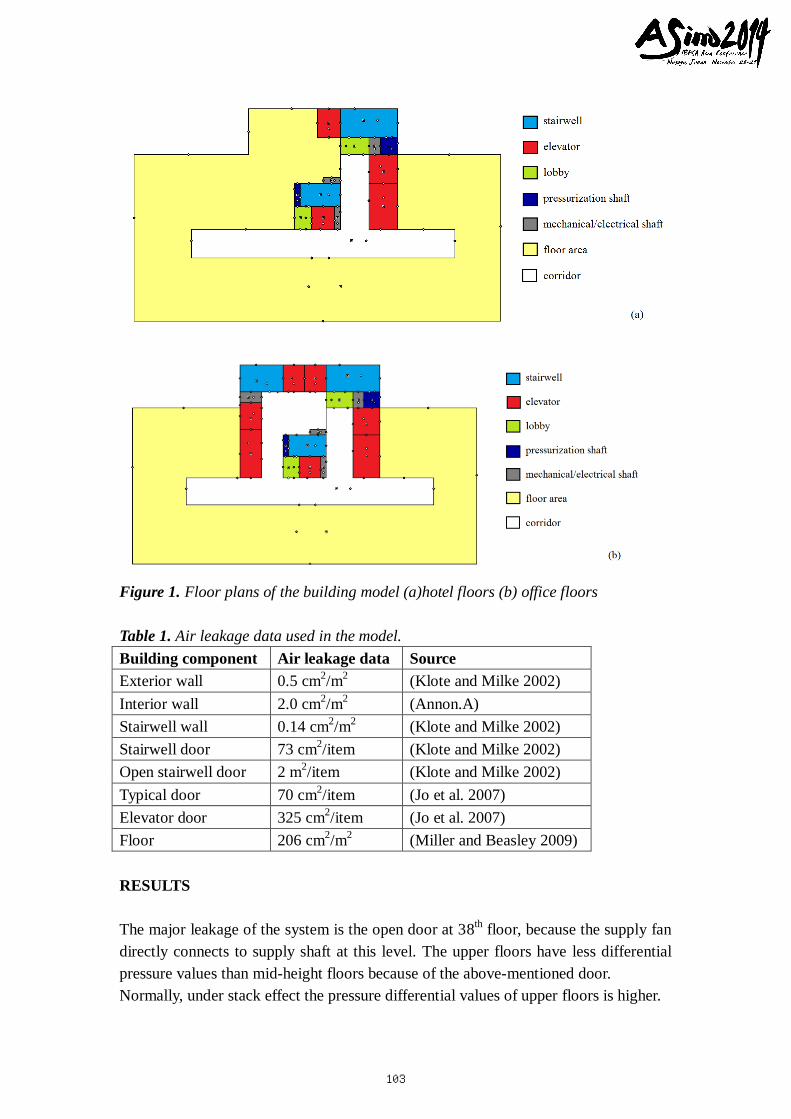
Figure 1. Floor plans of the building model (a)hotel floors (b) office floors
Table 1. Air leakage data used in the model.
Building component Air leakage data Source
Exterior wall 0.5 cm2/m
2 (Klote and Milke 2002)
Interior wall 2.0 cm2/m
2 (Annon.A)
Stairwell wall 0.14 cm2/m
2 (Klote and Milke 2002)
Stairwell door 73 cm2/item (Klote and Milke 2002)
Open stairwell door 2 m2/item (Klote and Milke 2002)
Typical door 70 cm2/item (Jo et al. 2007)
Elevator door 325 cm2/item (Jo et al. 2007)
Floor 206 cm2/m
2 (Miller and Beasley 2009)
RESULTS
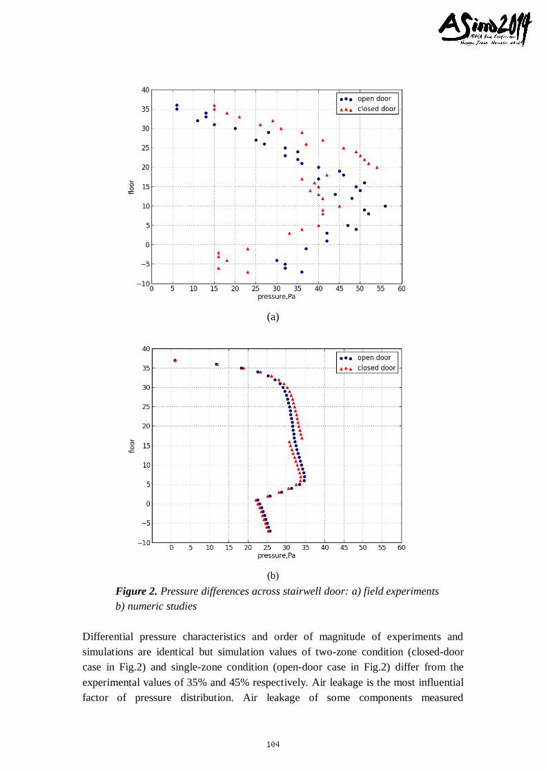
The major leakage of the system is the open door at 38th floor, because the supply fan
directly connects to supply shaft at this level. The upper floors have less differential
pressure values than mid-height floors because of the above-mentioned door.
Normally, under stack effect the pressure differential values of upper floors is higher.
103
(a)
(b)
Figure 2. Pressure differences across stairwell door: a) field experiments
b) numeric studies
Differential pressure characteristics and order of magnitude of experiments and
simulations are identical but simulation values of two-zone condition (closed-door
case in Fig.2) and single-zone condition (open-door case in Fig.2) differ from the
experimental values of 35% and 45% respectively. Air leakage is the most influential
factor of pressure distribution. Air leakage of some components measured
104
experimentally and used in CONTAM simulations in some studies in the literature (Jo
et al. 2007) (Miller and Beasley 2009). Instead of such a study, air leakages from
literature survey are used in this work.
Dividing the stairwell into two zones affects the differential pressure values to
distribute in a wider range for upper floors and a narrow range for the lower floors. It
is concluded both experimental and numerical studies that the air tends to flow from
upper zones to lower zones in stairwell; when the stairwell is composed of two zones
(closed door case in Fig.2), the differential pressure values of upper floors are
increased and lower floors are decreased.
Also, differential pressure distribution expands to a narrower range in closed-door
case, thus provides that the compartmantetion supports homogeneous pressure
distribution in the stairwell.
DISCUSSION
Instead of only one floor plan, three floor plans is used in order to accurately model
the building in this study because the building is a multi-purpose building. During
modeling process, pressure distribution characteristics consistent with experimental
results were obtained by using model with three different floor plans.
The most influential factor of differential pressure distribution through the stairwell is
the air leakage. While creating the building model, it is observed that the use of
different leakage area data change the results enormously. In order to determine the
appropriate coefficient of leakage area, calibration and experimental measurements
are executed in the some studies in literature (Jo et al. 2007) (Miller and Beasley
2009). Instead of such a study, leakage air data taken from literature. It is thought that
modeling the air leakage needs to be developed.
The supply air flow rate was obtained by an approximation in experimental study, in
which the air flow rate of the two open stairwell doors was measured and multiplied
with a safety factor. Using different values of the supply air flow did not change the
slope of the differential pressure versus floors, it changed only the values of
differential pressure values and it caused difference in between measured values and
simulation results.
CONCLUSION AND IMPLICATIONS
Compartmentation of stairwells is found in literature (Klote et al. 2012), but there is
not any study in the literature which investigates compartmentation. It is concluded
that compartmentation supports uniform pressure distribution on stairwells, however
it has needs to prevent pressure rise in upper floors by additional mechanisms if the
system is top injected.
105
REFERENCES
Anonymity. http://www.bfrl.nist.gov/IAQanalysis/CONTAM/, last accessed on 2
September 2014.
Anonymity A. http://www.bfrl.nist.gov/IAQanalysis/CONTAM/table03_res.htm, last
accessed on 2 September 2014
BSİ. 2005. BS EN 12101-6:2005, Smoke and Heat Control Systems – Part 6:
Specification for Pressure Differential Systems – Kits, United Kingdom: The
British Standards Institution.
Hepguzel, B. 2013. The effect of using relief damper in staircase pressurization as a
part of positive ventilation systems, Proceedings of the 7th Mediterranean
Conference of Climatization, pp.217-22.
Jo, J.H., Lim, J.H., Song, S.Y., Myoung-Souk, Y. and Kwang-Woo, K. 2007.
Characteristics of pressure distribution and solution to problem caused by stack
effect şn high-eise residential buildings, Building and Environment,Vol.42,
pp.13-17.
Lay, S. 2014. Pressurization systems do not work & present a risk to life safety, Case
Studies in Fire Safety, Vol.1, pp.13-17.
Klote, J.H., Ferreira, M.J., Kashef, A., Turnbull, P.G., and Milke, J.A. 2012.
Handbook of Smoke Control Engineering, American Society of Heating,
Refrigerating and Air-Conditioning Engineers.
Klote, J.H. and Milke, J.A. 2002. Principles of Smoke Management, American
Society of Heating, Refrigerating and Air-Conditioning Engineers.
Miller, R.S. and Beasley,D. 2009. On stairwell and elevator shaft pressurization for
smoke control in tall buildings, Building and Environment,Vol.44, pp.1306-1317.
NFPA. 2012. NFPA Standard 92, Standard for Smoke Control Systems,
Massachusetts: National Fire Protection Association.
TUYAK. 2012. Turkey’s Regulation on Fire Protection, Regulation Referring to the
Fire Protection of Buildings, İstanbul: Turkish Fire Protection and Education
Foundation.
106