Embed Size (px)
Citation preview
This paper discusses the structural behavior of reinforced concrete beams subjected to cyclic loadings by numerical and experimental analysis. The main objective was to quantify the increase in deflections of the beams when subjected to repeated loading cycles. Experimental tests with the application of cyclic and monotonic loading were carried out with reduced size beams. The numerical analysis utilized a simplified damage model that is part of the group denominated lumped dissipation models. This model takes into account the damage increase as a function of the increase in the number of cycles, enabling an evaluation of the stiffness loss due to repeated loads. The experimental results not only confirmed the effect of repeated loads on the stiffness loss of beams, but also demonstrated the important influence of the flexural reinforcement ratio on cyclic behavior. Comparisons between the experimental results and those obtained with the numerical model provided support for the potential of the damage model employed in the prediction of the increase of deflections caused by repeated cyclic loading.
Keywords: beams, reinforced concrete, cyclic loads, damage; stiffness loss.
O presente trabalho discute o comportamento estrutural de vigas de concreto armado submetidas a carregamentos cíclicos, através de análise numérica e experimental. O objetivo principal é quantificar o crescimento das flechas dessas vigas quando submetidas a ciclos de carga repetida. Foram realizados ensaios experimentais com vigas de tamanho reduzido, com aplicação de carregamento monotônico e cíclico. A análise nu-mérica utiliza um modelo simplificado de dano que se enquadra nos denominados modelos de dissipação concentrada. O referido modelo leva em conta o acréscimo de dano em função do aumento do número de ciclos, podendo assim avaliar a perda de rigidez das vigas decorrente das ações repetidas. Os resultados experimentais confirmaram não somente o efeito das ações repetidas na perda de rigidez das vigas, mas também reforçam a importante influência da taxa de armadura de flexão no comportamento cíclico. Comparações entre os resultados experimentais e os obtidos com o modelo numérico forneceram indícios do potencial do modelo de dano empregado para a previsão do crescimento de flechas com o car-regamento cíclico repetido.
Palavras-chave: vigas, concreto armado, ações cíclicas, dano, perda de rigidez.
Numerical and experimental analysis of the displacements evolution of reinforced concrete beams under repeated cyclic loads
Análise numérica e experimental da evolução de flechas de vigas de concreto armado sob ações cíclicas repetidas
J. OLIVEIRA FILHO a
G. M. S. ALVA b
R. M. F. CANHA c
A. L. H. C. EL DEBS d
a Universidade Federal de Sergipe, Departamento de Engenharia Civil, [email protected], Endereço: Avenida Marechal Rondon, s/n, Jardim Rosa Elze, CEP: 49100-000, São Cristóvão-SE, Brasil;b Universidade Federal de Santa Maria, Departamento de Estruturas e Construção Civil, [email protected], Endereço: Avenida Roraima, 1000, Cidade Universitária, CEP: 97105-900, Santa Maria-RS, Brasil;c Universidade Federal de Sergipe, Departamento de Engenharia Civil, [email protected], Endereço: Avenida Marechal Rondon, s/n, Jardim Rosa Elze, CEP: 49100-000, São Cristóvão-SE, Brasil;d Universidade de São Paulo – Escola de Engenharia de São Carlos, Departamento de Engenharia de Estruturas, [email protected]. Endereço: Av Trabalhador São-Carlense, 400, Arnold Schimidt, CEP: 13566-590, São Carlos – SP, Brasil
Received: 20 Nov 2010 • Accepted: 05 Jul 2011 • Available Online: 28 Nov 2011
Abstract
Resumo
Volume 4, Number 5 (December, 2011) p. 709-734 • ISSN 1983-4195
© 2011 IBRACON
710 IBRACON Structures and Materials Journal • 2011 • vol. 4 • nº 5
Numerical and experimental analysis of the displacements evolution of reinforced concrete beams under repeated cyclic loads
1. Introduction
Despite the significant development achieved in materials science and structural engineering during the last decades, the behavior of concrete is still considered as highly complex. The nonlinear behav-ior of concrete resulting from cracking starts even before its use with the micro cracking of the mortar matrix during curing process. This behavior is very difficult to be represented by numerical models even for monotonically loaded elements, and mainly for cyclic loading. Reinforced concrete behavior is highly affected by the steel-con-crete bond behavior, which is dependent of the type of applied load. Cyclic loading are characterized by the variation of stresses within a certain range with time. They provoke bond decay and strain increase due to the evolution of cracking process. Many studies have been conducted in the last years to investigate the influence of cyclic loads on reinforced concrete structures (including those using composite materials as reinforcement) mainly for the ulti-mate limit state of fatigue [1-4] and for the degradation of the steel-con-crete bond [5-9]. In Brazil, Braguim [10] and Oliveira Filho [11] studied the behavior of reinforced concrete beams under repeated loading.However, even with those numerous results, most of countries, including Brazil, have codes whose procedures are based on re-searches considering only monotonic loading. So, to understand the behavior of each component material, steel and concrete, and the behavior of both, forming a composite structure, still remain as challenges to be faced and motivation for new studies.
Present work has two main objectives: i) to present experimental re-sults showing the increase of deflections due to cyclic loading on re-inforced concrete beams, and ii) to propose a simple and consistent procedure to predict the deflection evolution during cycles, consid-ering the influence of important parameters as reinforcement ratio.The experimental results presented in this paper were obtained for the PhD thesis of Oliveira Filho [11] who performed an experi-mental investigation of the behavior of reinforced concrete beams submitted to monotonic and cyclic loads.The theoretical model proposed in this paper used a damage model based on Picón and Flórez-López [12]. A comparison be-tween theoretical and experimental results allowed the evalua-tion of the potential of the proposed model for simulations with repeated loads.
2. Tests on reinforced concrete beams
Tests on reinforced concrete beams under repeated cyclic loading were performed. In these tests, it was intended to determine the loss of rigidity caused by the imposed cyclic loading measuring vertical dis-placements and strains on concrete surface (compression zone) and in reinforcing bars. The used equipment consisted of an INSTRON testing machine with a servo-hydraulic actuator of 500kN capacity, from the Structural Laboratory of Sao Carlos Engineering School.In this paper, they are presented the tests results on seven beams subjected to cyclic loading and subsequent unloading and mono-tonic loading till failure.
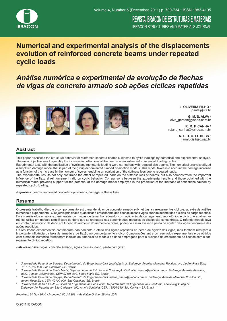
Figure 1 – Geometry and reinforcement layout of tested beams with rectangular cross section (dimensions in mm)
50 320 320 320 50
P/2 P/2
Ø 5 @ 80
VR-NA-CE
60
120 120Ø 6.3
Ø 5 @ 80
VR-AD-CE
60
Ø 10
Ø 4.2 Ø 5
711IBRACON Structures and Materials Journal • 2011 • vol. 4 • nº 5
J. OLIVEIRA FILHO | G. M. S. ALVA | R. M. F. CANHA | A. L. H. C. EL DEBS
mains 2 and 3, with stirrups (CE). First tested beam of the group was used as reference to evaluate the failure load and also to de-termine the frequency to be used in the cyclic loading of the 2 remaining beams (VR-NA-CE-01 and VR-NA-CE-02). Group II consisted also of 3 beams with rectangular cross section, designed with additional longitudinal compression reinforcement
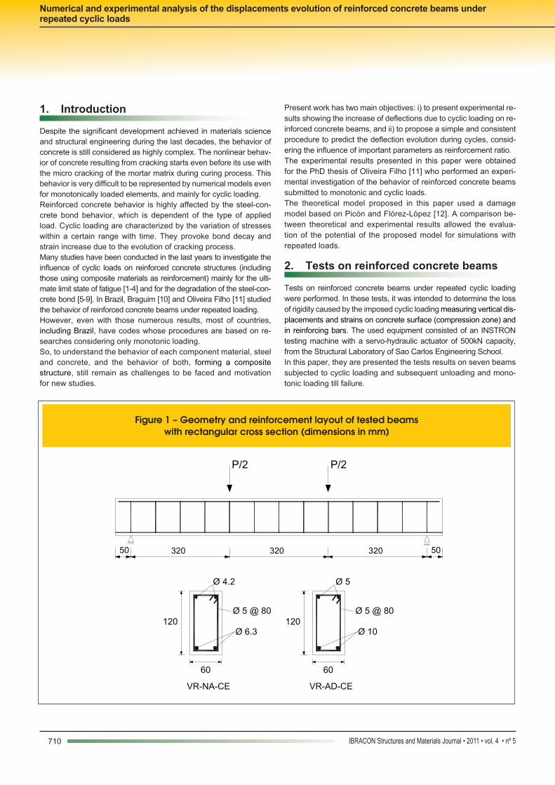
The beams were made in a reduced scale, with rectangular and T crosses sections. Figures 1 and 2 show the geometry, the rein-forcement details and the loading scheme used for tests.The beams were divided into 3 groups (I, II e III): Group I consisted of 3 beams with rectangular cross section, de-signed as normally reinforced ones (VR-NA), in the limit of do-
Figure 2 – Geometry and reinforcement layout of tested beam VT-NA-SE-02 (dimensions in mm)
50A
320
A
320
B
320 50
B
P/2 P/2
4040
Section A-A
80
Section B-B
Ø 5 @ 160
60
Ø 10 80 Ø 10
Ø 4.2 @ 160 Ø 4.2 40 4060
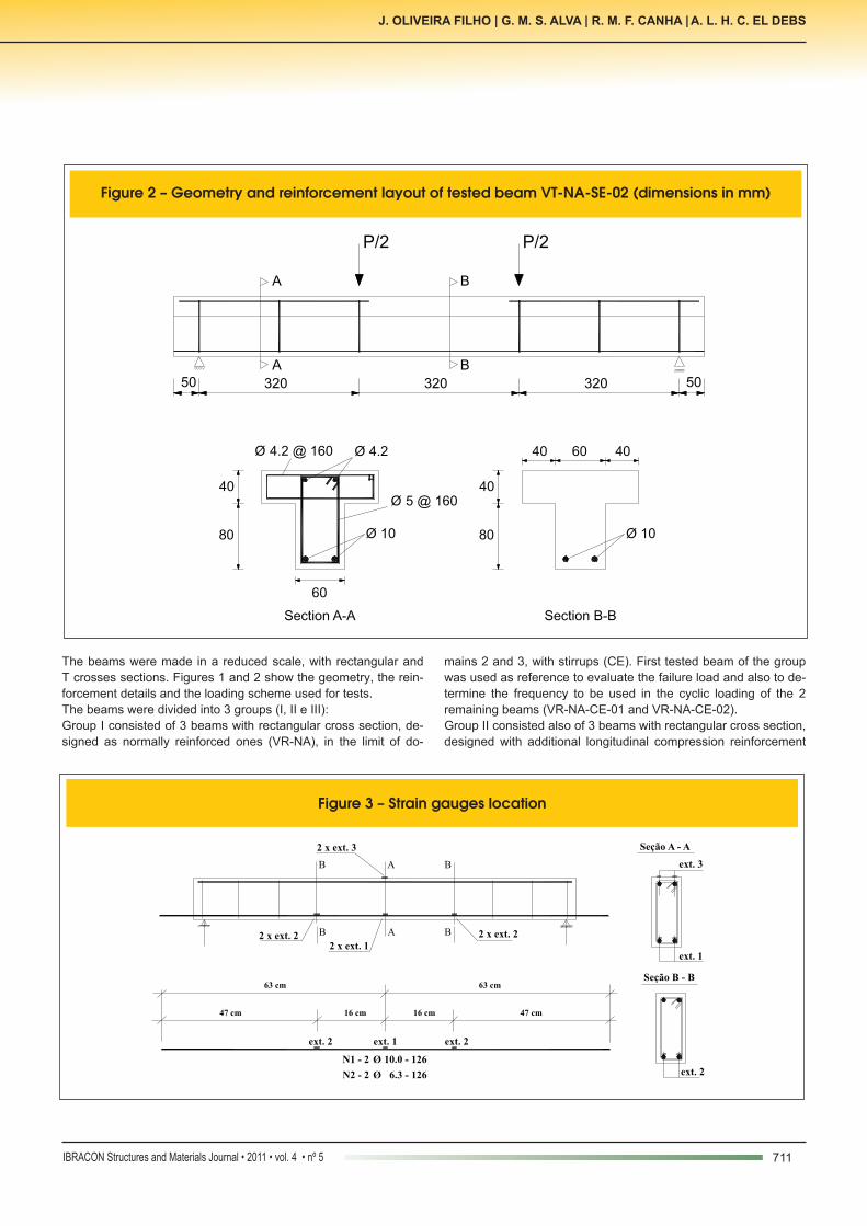
Figure 3 – Strain gauges location
ext. 2
47 cm
63 cm
N1 - 2 Ø 10.0 - 126
ext. 2
16 cm16 cm
ext. 1
47 cm
63 cm
B2 x ext. 2 B
2 x ext. 1
A
2 x ext. 3
B BA
2 x ext. 2
ext. 2
ext. 3
ext. 1
Seção A - A
Seção B - B
N2 - 2 Ø 6.3 - 126
712 IBRACON Structures and Materials Journal • 2011 • vol. 4 • nº 5
Numerical and experimental analysis of the displacements evolution of reinforced concrete beams under repeated cyclic loads
mm were made of CA-60 and bars of 6.3 mm and 10.0 mm were CA-50.Regarding concrete properties, tests performed gave the fol-lowing mean values: compres-sive strength of 40.19 MPa, se-cant elasticity modulus of 26781 MPa and tension strength (from Brazilian test) of 3.20 MPa.Measurements system con-sisted of electrical strain gaug-es placed on reinforcement
(VR-AD), to avoid neutral axis in Domain 4, and with stirrups (CE). As for the Group I, first tested beam of Group II (VR-AD-T) was taken as reference to evaluate the load capacity.Finally, Group III consisted of only one beam of T cross section, designed as normally reinforced (VT-NA), without stirrups (SE) in the zone of constant bending moment. Steel wires of 4.2 mm and 5.0
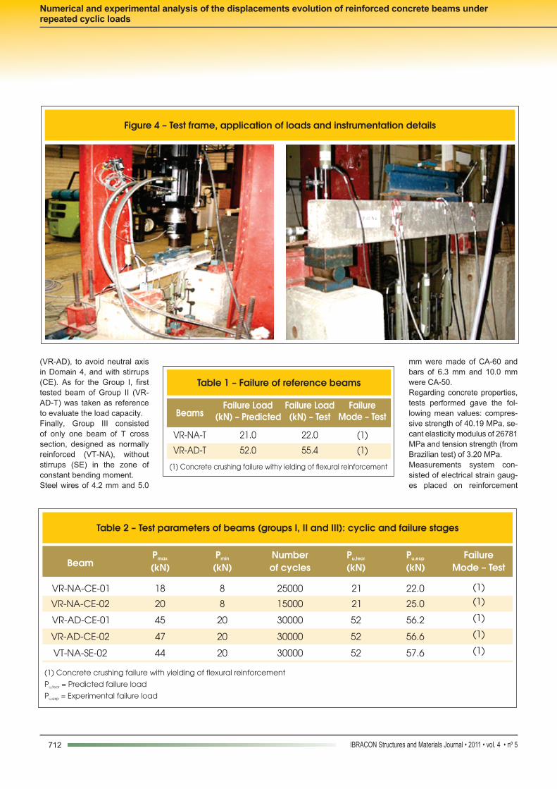
Figure 4 – Test frame, application of loads and instrumentation details
Table 1 – Failure of reference beams
Beams Failure Load
(kN) – Predicted Failure Load
(kN) – Test Failure
Mode – Test
VR-NA-T 21.0 22.0 (1)
VR-AD-T 52.0 55.4 (1)
(1) Concrete crushing failure withy ielding of flexural reinforcement
Table 2 – Test parameters of beams (groups I, II and III): cyclic and failure stages
Beam Pmax
(kN) Pmin
(kN) Number
of cycles Pu,teor
(kN) Pu,exp
(kN) Failure
Mode – Test
VR-NA-CE-01 18 8 25000 21 22.0 (1)
VR-NA-CE-02 20 8 15000 21 25.0 (1)
VR-AD-CE-01 45 20 30000 52 56.2 (1)
VR-AD-CE-02 47 20 30000 52 56.6 (1)
VT-NA-SE-02 44 20 30000 52 57.6 (1)
(1) Concrete crushing failure with yielding of flexural reinforcement
P = Predicted failure loadu,teor
P = Experimental failure loadu,exp
713IBRACON Structures and Materials Journal • 2011 • vol. 4 • nº 5
J. OLIVEIRA FILHO | G. M. S. ALVA | R. M. F. CANHA | A. L. H. C. EL DEBS
and concrete, for both groups of beams. Strain-gauges 1 and 2 were placed on reinforcement and 3 on the upper face of concrete beams, as shown in Figure 3.Figure 4 shows the test frame with the beam, the hydraulic actua-tor, the load cell and also the used instrumentation, supports and load system.At first, reference tests (T) were performed to determine the failure load. One beam of each group, I and II, were tested. The predicted failure loads and the obtained values are given in Table 1.Table 2 shows a summary of main tests parameters for the remain-ing beams of groups I, II and III.Predicted failure loads were obtained from usual calculation for reinforced concrete cross sections under flexure at ultimate limit state. Mean values of materials strength and deformability ob-tained in the characterization tests of steel and concrete were used in this calculation.
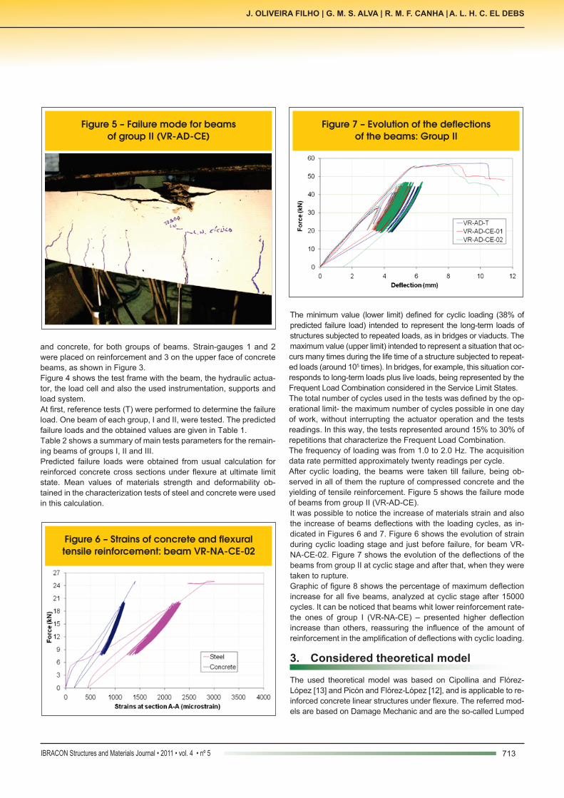
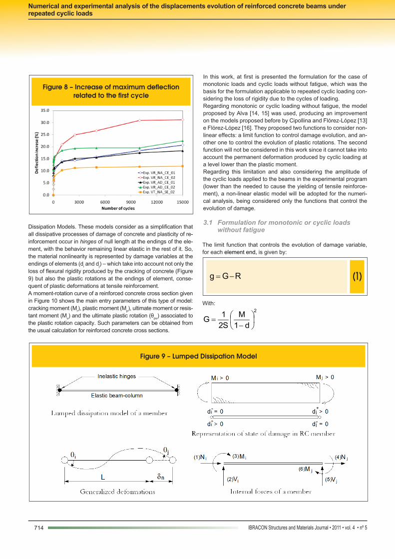
The minimum value (lower limit) defined for cyclic loading (38% of predicted failure load) intended to represent the long-term loads of structures subjected to repeated loads, as in bridges or viaducts. The maximum value (upper limit) intended to represent a situation that oc-curs many times during the life time of a structure subjected to repeat-ed loads (around 105 times). In bridges, for example, this situation cor-responds to long-term loads plus live loads, being represented by the Frequent Load Combination considered in the Service Limit States.The total number of cycles used in the tests was defined by the op-erational limit- the maximum number of cycles possible in one day of work, without interrupting the actuator operation and the tests readings. In this way, the tests represented around 15% to 30% of repetitions that characterize the Frequent Load Combination. The frequency of loading was from 1.0 to 2.0 Hz. The acquisition data rate permitted approximately twenty readings per cycle.After cyclic loading, the beams were taken till failure, being ob-served in all of them the rupture of compressed concrete and the yielding of tensile reinforcement. Figure 5 shows the failure mode of beams from group II (VR-AD-CE). It was possible to notice the increase of materials strain and also the increase of beams deflections with the loading cycles, as in-dicated in Figures 6 and 7. Figure 6 shows the evolution of strain during cyclic loading stage and just before failure, for beam VR-NA-CE-02. Figure 7 shows the evolution of the deflections of the beams from group II at cyclic stage and after that, when they were taken to rupture. Graphic of figure 8 shows the percentage of maximum deflection increase for all five beams, analyzed at cyclic stage after 15000 cycles. It can be noticed that beams whit lower reinforcement rate- the ones of group I (VR-NA-CE) – presented higher deflection increase than others, reassuring the influence of the amount of reinforcement in the amplification of deflections with cyclic loading.
3. Considered theoretical model
The used theoretical model was based on Cipollina and Flórez-López [13] and Picón and Flórez-López [12], and is applicable to re-inforced concrete linear structures under flexure. The referred mod-els are based on Damage Mechanic and are the so-called Lumped
Figure 5 – Failure mode for beams of group II (VR-AD-CE)
Figure 6 – Strains of concrete and flexural tensile reinforcement: beam VR-NA-CE-02
Figure 7 – Evolution of the deflections of the beams: Group II
714 IBRACON Structures and Materials Journal • 2011 • vol. 4 • nº 5
Numerical and experimental analysis of the displacements evolution of reinforced concrete beams under repeated cyclic loads
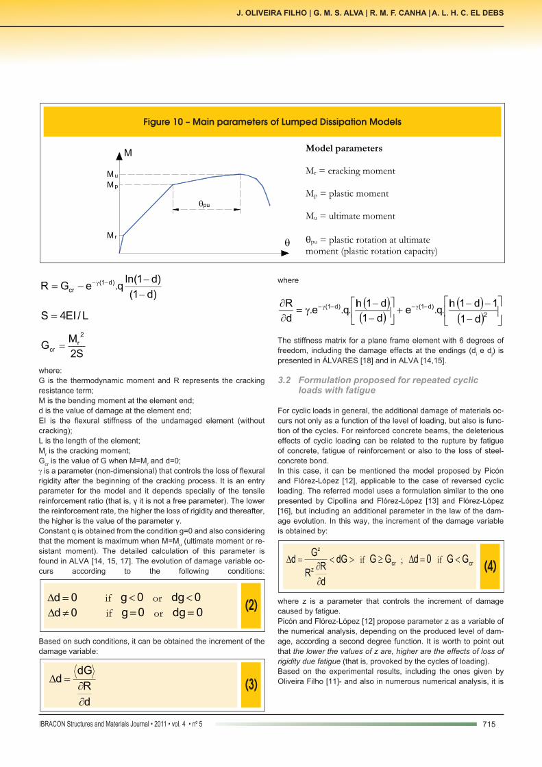
Dissipation Models. These models consider as a simplification that all dissipative processes of damage of concrete and plasticity of re-inforcement occur in hinges of null length at the endings of the ele-ment, with the behavior remaining linear elastic in the rest of it. So, the material nonlinearity is represented by damage variables at the endings of elements (di and dj) – which take into account not only the loss of flexural rigidity produced by the cracking of concrete (Figure 9) but also the plastic rotations at the endings of element, conse-quent of plastic deformations at tensile reinforcement. A moment-rotation curve of a reinforced concrete cross section given in Figure 10 shows the main entry parameters of this type of model: cracking moment (Mr), plastic moment (Mp), ultimate moment or resis-tant moment (Mu) and the ultimate plastic rotation (θpu) associated to the plastic rotation capacity. Such parameters can be obtained from the usual calculation for reinforced concrete cross sections.
In this work, at first is presented the formulation for the case of monotonic loads and cyclic loads without fatigue, which was the basis for the formulation applicable to repeated cyclic loading con-sidering the loss of rigidity due to the cycles of loading. Regarding monotonic or cyclic loading without fatigue, the model proposed by Alva [14, 15] was used, producing an improvement on the models proposed before by Cipollina and Flórez-López [13] e Flórez-López [16]. They proposed two functions to consider non-linear effects: a limit function to control damage evolution, and an-other one to control the evolution of plastic rotations. The second function will not be considered in this work since it cannot take into account the permanent deformation produced by cyclic loading at a level lower than the plastic moment.Regarding this limitation and also considering the amplitude of the cyclic loads applied to the beams in the experimental program (lower than the needed to cause the yielding of tensile reinforce-ment), a non-linear elastic model will be adopted for the numeri-cal analysis, being considered only the functions that control the evolution of damage.
3.1 Formulation for monotonic or cyclic loads without fatigue
The limit function that controls the evolution of damage variable, for each element end, is given by:
(1) RGg -=
With:2
d1M
S21G
−=
Figure 8 – Increase of maximum deflection related to the first cycle
Figure 9 – Lumped Dissipation Model
715IBRACON Structures and Materials Journal • 2011 • vol. 4 • nº 5
J. OLIVEIRA FILHO | G. M. S. ALVA | R. M. F. CANHA | A. L. H. C. EL DEBS
)d1(
)d1ln(q.eGR )d1(
cr-
--= -g-
L/EI4S =
S2
MG
2
rcr =
where:G is the thermodynamic moment and R represents the cracking resistance term;M is the bending moment at the element end;d is the value of damage at the element end;EI is the flexural stiffness of the undamaged element (without cracking);L is the length of the element;Mr is the cracking moment;Gcr is the value of G when M=Mr and d=0;γ is a parameter (non-dimensional) that controls the loss of flexural rigidity after the beginning of the cracking process. It is an entry parameter for the model and it depends specially of the tensile reinforcement ratio (that is, γ it is not a free parameter). The lower the reinforcement rate, the higher the loss of rigidity and thereafter, the higher is the value of the parameter γ. Constant q is obtained from the condition g=0 and also considering that the moment is maximum when M=Mu (ultimate moment or re-sistant moment). The detailed calculation of this parameter is found in ALVA [14, 15, 17]. The evolution of damage variable oc-curs according to the following conditions:
(2)0d =D if 0g< or 0dg<
0d ¹D if 0g= or 0dg =
Based on such conditions, it can be obtained the increment of the damage variable:
(3)
d
R
dGd
¶=D
where
( )( )
( )( )
−−−
+
−−
γ=∂∂ −γ−−γ−
2)d1()d1(
d11d1ln.q.e
d1d1ln.q.e.
dR
The stiffness matrix for a plane frame element with 6 degrees of freedom, including the damage effects at the endings (di e dj) is presented in ÁLVARES [18] and in ALVA [14,15].
3.2 Formulation proposed for repeated cyclic loads with fatigue
For cyclic loads in general, the additional damage of materials oc-curs not only as a function of the level of loading, but also is func-tion of the cycles. For reinforced concrete beams, the deleterious effects of cyclic loading can be related to the rupture by fatigue of concrete, fatigue of reinforcement or also to the loss of steel-concrete bond. In this case, it can be mentioned the model proposed by Picón and Flórez-López [12], applicable to the case of reversed cyclic loading. The referred model uses a formulation similar to the one presented by Cipollina and Flórez-López [13] and Flórez-López [16], but including an additional parameter in the law of the dam-age evolution. In this way, the increment of the damage variable is obtained by:
(4)><
¶=D dG
d
RR
Gd
z
z
if crGG ³ ; 0d =D if crGG <
where z is a parameter that controls the increment of damage caused by fatigue.Picón and Flórez-López [12] propose parameter z as a variable of the numerical analysis, depending on the produced level of dam-age, according a second degree function. It is worth to point out that the lower the values of z are, higher are the effects of loss of rigidity due fatigue (that is, provoked by the cycles of loading). Based on the experimental results, including the ones given by Oliveira Filho [11]- and also in numerous numerical analysis, it is
Figure 10 – Main parameters of Lumped Dissipation Models
Model parameters Mr = cracking moment Mp = plastic moment Mu = ultimate moment
qpu = plastic rotation at ultimate moment (plastic rotation capacity)
rM
M
M p
M u
q
puq
716 IBRACON Structures and Materials Journal • 2011 • vol. 4 • nº 5
Numerical and experimental analysis of the displacements evolution of reinforced concrete beams under repeated cyclic loads
proposed in this work that the parameter z is determined from the following general expression for the case of repeated cyclic loading:
(5) 4d.Az =
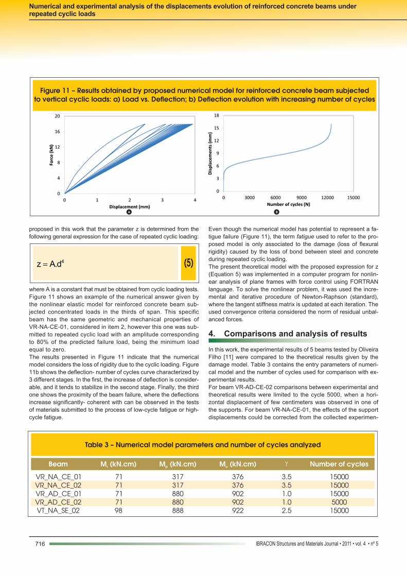
where A is a constant that must be obtained from cyclic loading tests.Figure 11 shows an example of the numerical answer given by the nonlinear elastic model for reinforced concrete beam sub-jected concentrated loads in the thirds of span. This specific beam has the same geometric and mechanical properties of VR-NA-CE-01, considered in item 2, however this one was sub-mitted to repeated cyclic load with an amplitude corresponding to 80% of the predicted failure load, being the minimum load equal to zero. The results presented in Figure 11 indicate that the numerical model considers the loss of rigidity due to the cyclic loading. Figure 11b shows the deflection- number of cycles curve characterized by 3 different stages. In the first, the increase of deflection is consider-able, and it tends to stabilize in the second stage. Finally, the third one shows the proximity of the beam failure, where the deflections increase significantly- coherent with can be observed in the tests of materials submitted to the process of low-cycle fatigue or high-cycle fatigue.
Even though the numerical model has potential to represent a fa-tigue failure (Figure 11), the term fatigue used to refer to the pro-posed model is only associated to the damage (loss of flexural rigidity) caused by the loss of bond between steel and concrete during repeated cyclic loading.The present theoretical model with the proposed expression for z (Equation 5) was implemented in a computer program for nonlin-ear analysis of plane frames with force control using FORTRAN language. To solve the nonlinear problem, it was used the incre-mental and iterative procedure of Newton-Raphson (standard), where the tangent stiffness matrix is updated at each iteration. The used convergence criteria considered the norm of residual unbal-anced forces. 4. Comparisons and analysis of results
In this work, the experimental results of 5 beams tested by Oliveira Filho [11] were compared to the theoretical results given by the damage model. Table 3 contains the entry parameters of numeri-cal model and the number of cycles used for comparison with ex-perimental results. For beam VR-AD-CE-02 comparisons between experimental and theoretical results were limited to the cycle 5000, when a hori-zontal displacement of few centimeters was observed in one of the supports. For beam VR-NA-CE-01, the effects of the support displacements could be corrected from the collected experimen-
Figure 11 – Results obtained by proposed numerical model for reinforced concrete beam subjected to vertical cyclic loads: a) Load vs. Deflection; b) Deflection evolution with increasing number of cycles
A B
Table 3 – Numerical model parameters and number of cycles analyzed
Beam M (kN.cm)r M (kN.cm)p M (kN.cm)u g Number of cycles
VR_NA_CE_01 71 317 376 3.5 15000 VR_NA_CE_02 71 317 376 3.5 15000 VR_AD_CE_01 71 880 902 1.0 15000 VR_AD_CE_02 71 880 902 1.0 5000 VT_NA_SE_02 98 888 922 2.5 15000
717IBRACON Structures and Materials Journal • 2011 • vol. 4 • nº 5
J. OLIVEIRA FILHO | G. M. S. ALVA | R. M. F. CANHA | A. L. H. C. EL DEBS
tal results and also from the analysis of observed tendency of deflections increase. Parameters Mr, Mp and Mu were obtained from the experimental results. For a good prediction of parameter γ, numerical simula-tions using a more precise model were performed. Such model consisted of the discretization of the beam in 12 elements using moment-curvature diagrams to obtain the flexural stiffness of ele-ments. For behavior in service, Branson expression was used. Be-havior at ultimate limit state was represented by a linear branch for moment–curvature diagram between the beginning of reinforce-ment plastic behavior and the ultimate moment. Considering the load-deflection diagrams given by the damage model and also by the refined model, values for γ were obtained and are shown in Table 3.Graphics of Figures 12 to 16 indicate the increase of beams de-flections along the cycles of loading (related to the first cycle). In those figures are shown the most adequate values of constant A regarding the experimental results. The graphics of Figures 12 to 16 show that the proposed model presents a good potential to predict the stiffness loss and the de-flection increase that occurs in reinforced concrete beams subject-ed to repeated cyclic loading. However, it is necessary a careful evaluation of the values assumed by constant A in function of the many variables affecting the problem solution.
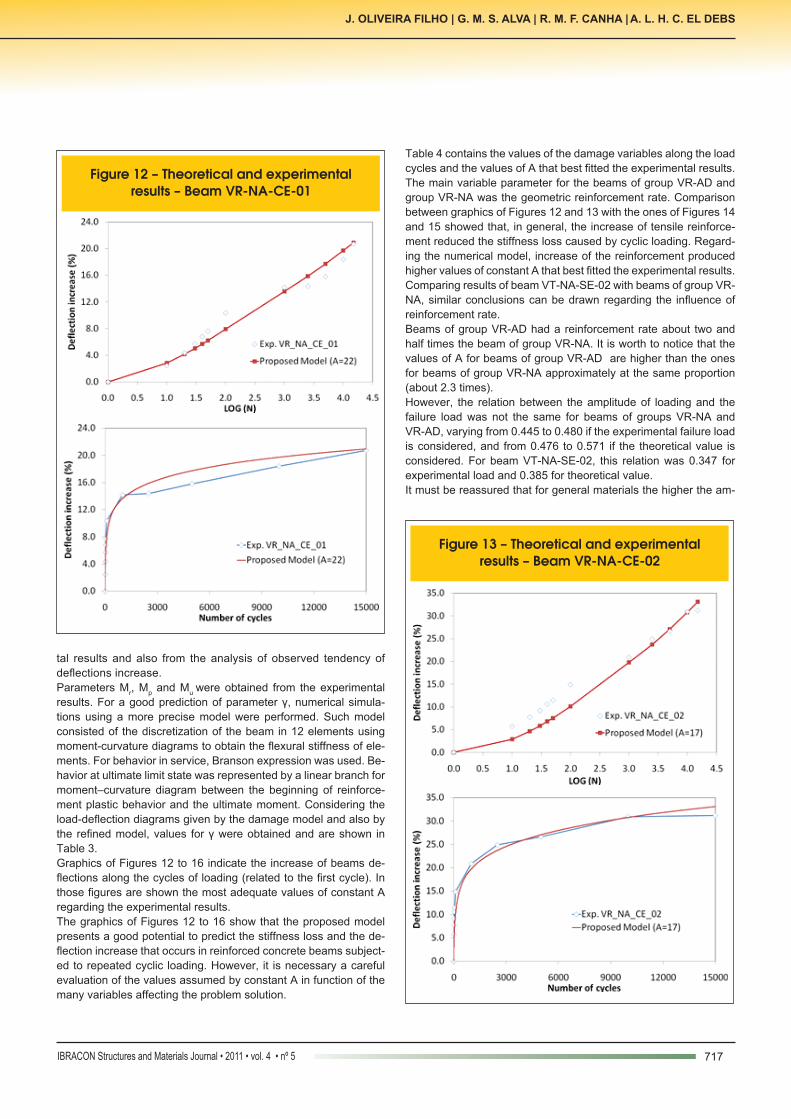
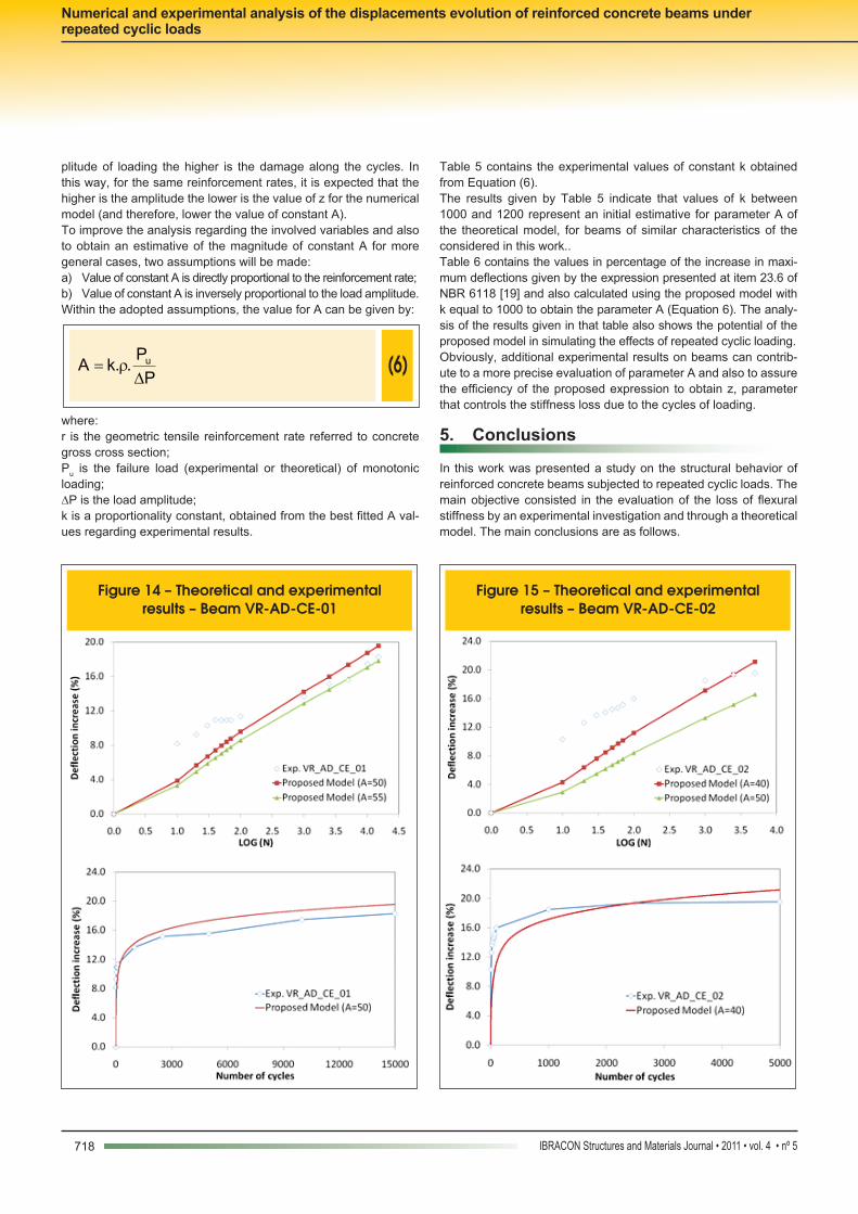
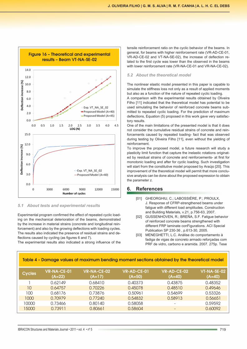
Table 4 contains the values of the damage variables along the load cycles and the values of A that best fitted the experimental results.The main variable parameter for the beams of group VR-AD and group VR-NA was the geometric reinforcement rate. Comparison between graphics of Figures 12 and 13 with the ones of Figures 14 and 15 showed that, in general, the increase of tensile reinforce-ment reduced the stiffness loss caused by cyclic loading. Regard-ing the numerical model, increase of the reinforcement produced higher values of constant A that best fitted the experimental results. Comparing results of beam VT-NA-SE-02 with beams of group VR-NA, similar conclusions can be drawn regarding the influence of reinforcement rate.Beams of group VR-AD had a reinforcement rate about two and half times the beam of group VR-NA. It is worth to notice that the values of A for beams of group VR-AD are higher than the ones for beams of group VR-NA approximately at the same proportion (about 2.3 times).However, the relation between the amplitude of loading and the failure load was not the same for beams of groups VR-NA and VR-AD, varying from 0.445 to 0.480 if the experimental failure load is considered, and from 0.476 to 0.571 if the theoretical value is considered. For beam VT-NA-SE-02, this relation was 0.347 for experimental load and 0.385 for theoretical value.It must be reassured that for general materials the higher the am-
Figure 12 – Theoretical and experimental results – Beam VR-NA-CE-01
Figure 13 – Theoretical and experimental results – Beam VR-NA-CE-02
718 IBRACON Structures and Materials Journal • 2011 • vol. 4 • nº 5
Numerical and experimental analysis of the displacements evolution of reinforced concrete beams under repeated cyclic loads
Figure 14 – Theoretical and experimental results – Beam VR-AD-CE-01
Figure 15 – Theoretical and experimental results – Beam VR-AD-CE-02
plitude of loading the higher is the damage along the cycles. In this way, for the same reinforcement rates, it is expected that the higher is the amplitude the lower is the value of z for the numerical model (and therefore, lower the value of constant A).To improve the analysis regarding the involved variables and also to obtain an estimative of the magnitude of constant A for more general cases, two assumptions will be made: a) Value of constant A is directly proportional to the reinforcement rate; b) Value of constant A is inversely proportional to the load amplitude. Within the adopted assumptions, the value for A can be given by:
(6)
P
P..kA u
Dr=
where:r is the geometric tensile reinforcement rate referred to concrete gross cross section; Pu is the failure load (experimental or theoretical) of monotonic loading;∆P is the load amplitude;k is a proportionality constant, obtained from the best fitted A val-ues regarding experimental results.
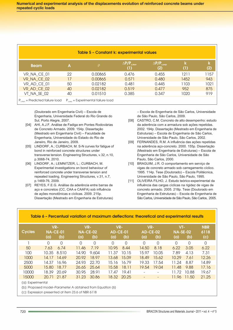
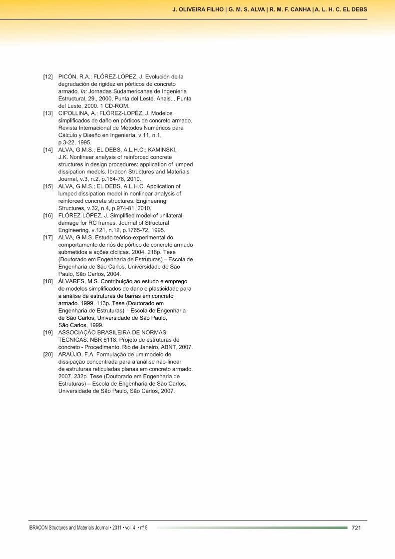
Table 5 contains the experimental values of constant k obtained from Equation (6).The results given by Table 5 indicate that values of k between 1000 and 1200 represent an initial estimative for parameter A of the theoretical model, for beams of similar characteristics of the considered in this work..Table 6 contains the values in percentage of the increase in maxi-mum deflections given by the expression presented at item 23.6 of NBR 6118 [19] and also calculated using the proposed model with k equal to 1000 to obtain the parameter A (Equation 6). The analy-sis of the results given in that table also shows the potential of the proposed model in simulating the effects of repeated cyclic loading. Obviously, additional experimental results on beams can contrib-ute to a more precise evaluation of parameter A and also to assure the efficiency of the proposed expression to obtain z, parameter that controls the stiffness loss due to the cycles of loading.
5. Conclusions
In this work was presented a study on the structural behavior of reinforced concrete beams subjected to repeated cyclic loads. The main objective consisted in the evaluation of the loss of flexural stiffness by an experimental investigation and through a theoretical model. The main conclusions are as follows.
719IBRACON Structures and Materials Journal • 2011 • vol. 4 • nº 5
J. OLIVEIRA FILHO | G. M. S. ALVA | R. M. F. CANHA | A. L. H. C. EL DEBS
Figure 16 – Theoretical and experimental results – Beam VT-NA-SE-02
Table 4 – Damage values at maximum bending moment sections obtained by the theoretical model
Cycles VR-NA-CE-01(A=22)
VR-NA-CE-02(A=17)
VR-AD-CE-01(A=50)
VR-AD-CE-02(A=40)
VT-NA-SE-02(A=40)
1 0.62149 0.68410 0.40373 0.43875 0.48352 10 0.64757 0.70226 0.45078 0.48510 0.49646 100 0.68176 0.73876 0.50961 0.54699 0.53326 1000 0.70979 0.77240 0.54832 0.58913 0.56651 10000 0.73466 0.80140 0.58058 - 0.59592 15000 0.73911 0.80661 0.58604 - 0.60092
5.1 About tests and experimental results
Experimental program confirmed the effect of repeated cyclic load-ing on the mechanical deterioration of the beams, demonstrated by the increase in material strains (concrete and longitudinal rein-forcement) and also by the growing deflections with loading cycles. The results also indicated the presence of residual strains and de-flections caused by cycling (as figures 6 and 7).The experimental results also indicated a strong influence of the
tensile reinforcement ratio on the cyclic behavior of the beams. In general, for beams with higher reinforcement rate (VR-AD-CE-01, VR-AD-CE-02 and VT-NA-SE-02), the increase of deflection re-lated to the first cycle was lower than the observed in the beams with lower reinforcement rate (VR-NA-CE-01 and VR-NA-CE-02).
5.2 About the theoretical model
The nonlinear elastic model presented in this paper is capable to simulate the stiffness loss not only as a result of applied moments but also as a function of the nature of repeated cyclic loading.A comparison with the experimental results obtained by Oliveira Filho [11] indicated that the theoretical model has potential to be used simulating the behavior of reinforced concrete beams sub-mitted to repeated cyclic loading. For the prediction of maximum deflections, Equation (5) proposed in this work gave very satisfac-tory results. One of the main limitations of the presented model is that it does not consider the cumulative residual strains of concrete and rein-forcements caused by repeated loading- fact that was observed during testing by Oliveira Filho [11], even without the yielding of reinforcement. To improve the proposed model, a future research will study a plasticity limit function that capture the inelastic rotations originat-ed by residual strains of concrete and reinforcements- at first for monotonic loading and after for cyclic loading. Such investigation will start from the constitutive model proposed by Araújo [20]. This improvement of the theoretical model will permit that more conclu-sive analysis can be done about the proposed expression to obtain the parameter z.
6. References
[01] GHEORGHIU, C.; LABOSSIÈRE, P.; PROULX, J. Response of CFRP-strengthened beams under fatigue with different load amplitudes. Construction
and Building Materials, v.21, p.756-63, 2007. [02] GUSSENHOVEN, R.; BREÑA, S.F. Fatigue behavior
of reinforced concrete beams strengthened with different FRP laminate conFigurations. ACI Special
Publication SP 230-36 , p.613-30, 2005. [03] MENEGHETTI, L.C. Análise do comportamento à fadiga de vigas de concreto armado reforçadas com
PRF de vidro, carbono e aramida. 2007. 275p. Tese
720 IBRACON Structures and Materials Journal • 2011 • vol. 4 • nº 5
Numerical and experimental analysis of the displacements evolution of reinforced concrete beams under repeated cyclic loads
(Doutorado em Engenharia Civil) – Escola de Engenharia, Universidade Federal do Rio Grande do
Sul, Porto Alegre, 2007. [04] AHI, A.J.F. Análise de Fadiga em Pontes Rodoviárias
de Concreto Armado. 2009. 154p. Dissertação (Mestrado em Engenharia Civil) – Faculdade de Engenharia, Universidade do Estado do Rio de Janeiro, Rio de Janeiro, 2009. [05] LINDORF, A.; CURBACH, M. S-N curves for fatigue of bond in reinforced concrete structures under transverse tension. Engineering Structures, v.32, n.10, p.3068-74, 2010. [06] LINDORF, A.; LEMNITZER, L.; CURBACH, M. Experimental investigations on bond behaviour of reinforced concrete under transverse tension and repeated loading. Engineering Structures, v.31, n.7,
p.1469-76, 2009. [07] REYES, F.E.G. Análise da aderência entre barras de
aço e concretos (CC, CAA e CAAFA) sob influência de ações monotônicas e cíclicas. 2009. 215p.
Dissertação (Mestrado em Engenharia de Estruturas)
– Escola de Engenharia de São Carlos, Universidade de São Paulo, São Carlos, 2009.
[08] CASTRO, C.M. Concreto de alto desempenho: estudo da aderência com a armadura sob ações repetidas.
2002. 194p. Dissertação (Mestrado em Engenharia de Estruturas) – Escola de Engenharia de São Carlos,
Universidade de São Paulo, São Carlos, 2002. [09] FERNANDES, R.M. A influência das ações repetidas
na aderência aço-concreto. 2000. 155p. Dissertação (Mestrado em Engenharia de Estruturas) – Escola de Engenharia de São Carlos, Universidade de São
Paulo, São Carlos, 2000. [10] BRAGUIM, J.R. O comportamento em serviço de vigas de concreto armado sob carregamento cíclico.
1995. 114p. Tese (Doutorado) – Escola Politécnica, Universidade de São Paulo, São Paulo, 1995.
[11] OLIVEIRA FILHO, J. Estudo teórico-experimental da influência das cargas cíclicas na rigidez de vigas de concreto armado. 2005. 218p. Tese (Doutorado em Engenharia de Estruturas) – Escola de Engenharia de
São Carlos, Universidade de São Paulo, São Carlos, 2005.
Table 5 – Constant k: experimental values
Beam A r DP/Pu,teor
(1)DP/Pu,exp
(2)k
(1)k
(2)
VR_NA_CE_01 22 0.00865 0.476 0.455 1211 1157 VR_NA_CE_02 17 0.00865 0.571 0.480 1452 943 VR_AD_CE_01 50 0.02182 0.481 0.445 1103 1021 VR_AD_CE_02 40 0.02182 0.519 0.477 952 875 VT_NA_SE_02 40 0.01510 0.385 0.347 1020 919
P = Predicted failure loadu,teor P = Experimental failure loadu,exp
Table 6 – Percentual variation of maximum deflections: theoretical and experimental results
Cycles VR-
NA-CE-01 VR-
NA-CE-02VR-
AD-CE-01 VR-
AD-CE-02 VT-
NA-SE-02 NBR 6118
(a) (b) (a) (b) (a) (b) (a) (b) (a) (b) (c) 1 0 0 0 0 0 0 0 0 0 0 0
50 7.63 6.74 11.46 7.19 10.95 8.44 14.50 8.18 6.22 3.05 6.22 100 10.35 8.510 14.90 9.604 11.37 10.15 15.97 10.05 7.89 4.13 7.31 1000 14.17 14.69 20.92 18.97 13.68 15.09 18.49 15.62 10.29 7.61 12.26 2500 14.37 16.96 24.93 22.70 15.16 16.79 19.33 17.54 11.24 8.87 14.89 5000 15.80 18.77 26.65 25.64 15.58 18.11 19.54 19.04 11.48 9.88 17.16 10000 18.39 20.69 30.95 28.91 17.47 19.41 - - 11.72 10.88 19.67 15000 20.71 21.87 31.23 30.86 18.32 20.25 - - 11.96 11.50 21.25
(a): Experimental
(b): Proposed model–Parameter A obtained from Equation (6)
(c): Expression presented at item 23.6 of NBR 6118
721IBRACON Structures and Materials Journal • 2011 • vol. 4 • nº 5
J. OLIVEIRA FILHO | G. M. S. ALVA | R. M. F. CANHA | A. L. H. C. EL DEBS
[12] PICÓN, R.A.; FLÓREZ-LÓPEZ, J. Evolución de la degradación de rigidez en pórticos de concreto
armado. In: Jornadas Sudamericanas de Ingenieria Estructural, 29., 2000, Punta del Leste. Anais... Punta del Leste, 2000. 1 CD-ROM.
[13] CIPOLLINA, A.; FLÓREZ-LOPÉZ, J. Modelos simplificados de daño en pórticos de concreto armado. Revista Internacional de Métodos Numéricos para
Cálculo y Diseño en Ingeniería, v.11, n.1, p.3-22, 1995. [14] ALVA, G.M.S.; EL DEBS, A.L.H.C.; KAMINSKI, J.K. Nonlinear analysis of reinforced concrete structures in design procedures: application of lumped dissipation models. Ibracon Structures and Materials
Journal, v.3, n.2, p.164-78, 2010. [15] ALVA, G.M.S.; EL DEBS, A.L.H.C. Application of
lumped dissipation model in nonlinear analysis of reinforced concrete structures. Engineering Structures, v.32, n.4, p.974-81, 2010. [16] FLÓREZ-LÓPEZ, J. Simplified model of unilateral
damage for RC frames. Journal of Structural Engineering, v.121, n.12, p.1765-72, 1995. [17] ALVA, G.M.S. Estudo teórico-experimental do comportamento de nós de pórtico de concreto armado submetidos a ações cíclicas. 2004. 218p. Tese (Doutorado em Engenharia de Estruturas) – Escola de Engenharia de São Carlos, Universidade de São Paulo, São Carlos, 2004. [18] ÁLVARES, M.S. Contribuição ao estudo e emprego de modelos simplificados de dano e plasticidade para
a análise de estruturas de barras em concreto armado. 1999. 113p. Tese (Doutorado em Engenharia de Estruturas) – Escola de Engenharia de São Carlos, Universidade de São Paulo, São Carlos, 1999. [19] ASSOCIAÇÃO BRASILEIRA DE NORMAS TÉCNICAS. NBR 6118: Projeto de estruturas de concreto - Procedimento. Rio de Janeiro, ABNT, 2007. [20] ARAÚJO, F.A. Formulação de um modelo de dissipação concentrada para a análise não-linear de estruturas reticuladas planas em concreto armado. 2007. 232p. Tese (Doutorado em Engenharia de Estruturas) – Escola de Engenharia de São Carlos,
Universidade de São Paulo, São Carlos, 2007.