Embed Size (px)
Citation preview
National Aeronautics and Space Administration
www.nasa.govASM 2017 1
SciTech 201755nd AIAA Aerospace Sciences Meeting
Grapevine, TexasJanuary 9-13, 2017
Numerical and Analytical Assessment of a Coupled Rotating Detonation Engine and Turbine Experiment
Daniel E. PaxsonNASA Glenn Research Center
Cleveland, Ohio
Andrew NaplesInnovative Scientific Solutions Inc.
Dayton, Ohio
https://ntrs.nasa.gov/search.jsp?R=20170005180 2020-04-18T20:24:46+00:00Z
National Aeronautics and Space Administration
www.nasa.govASM 2017 2
Outline
• Background/Motivation• Experiment Description• Model Approach• Results• Concluding Remarks

National Aeronautics and Space Administration
www.nasa.gov 3ASM 2017
BackgroundRotating Detonation Engines (RDE’s) represent an IntriguingApproach to Detonative Pressure Gain Combustion (PGC)
• 1000+ Hz. cycle frequency• No ‘spark’ required• No lossy DDT devices• Compact
PGC: A periodic process, in a fixed volume, whereby gas expansion by heat release is constrained, causing a rise in stagnation pressure and allowing work extraction by expansion to the initial pressure.
Source: Schwer, AIAA 2011-581
Tem
pera
tureP
ress
ure
National Aeronautics and Space Administration
www.nasa.govASM 2017 4
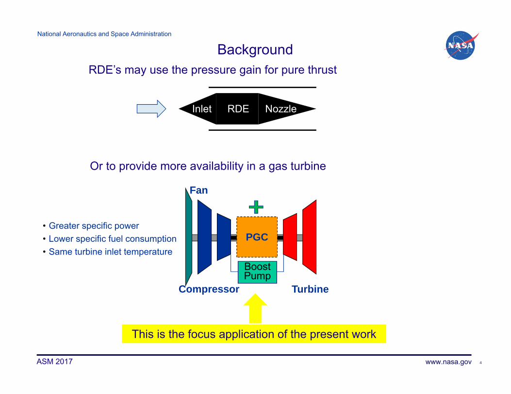
Background
RDEInlet Nozzle
RDE’s may use the pressure gain for pure thrust
Or to provide more availability in a gas turbine
Turbine
PGC
Compressor
BoostPump
Fan
• Greater specific power• Lower specific fuel consumption• Same turbine inlet temperature
This is the focus application of the present work
National Aeronautics and Space Administration
www.nasa.govASM 2017 5
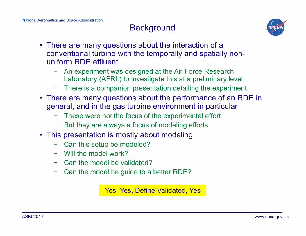
Yes, Yes, Define Validated, Yes
Background
• There are many questions about the interaction of a conventional turbine with the temporally and spatially non-uniform RDE effluent.− An experiment was designed at the Air Force Research
Laboratory (AFRL) to investigate this at a preliminary level− There is a companion presentation detailing the experiment
• There are many questions about the performance of an RDE in general, and in the gas turbine environment in particular− These were not the focus of the experimental effort− But they are always a focus of modeling efforts
• This presentation is mostly about modeling− Can this setup be modeled?− Will the model work?− Can the model be validated?− Can the model be guide to a better RDE?

National Aeronautics and Space Administration
www.nasa.govASM 2017 6
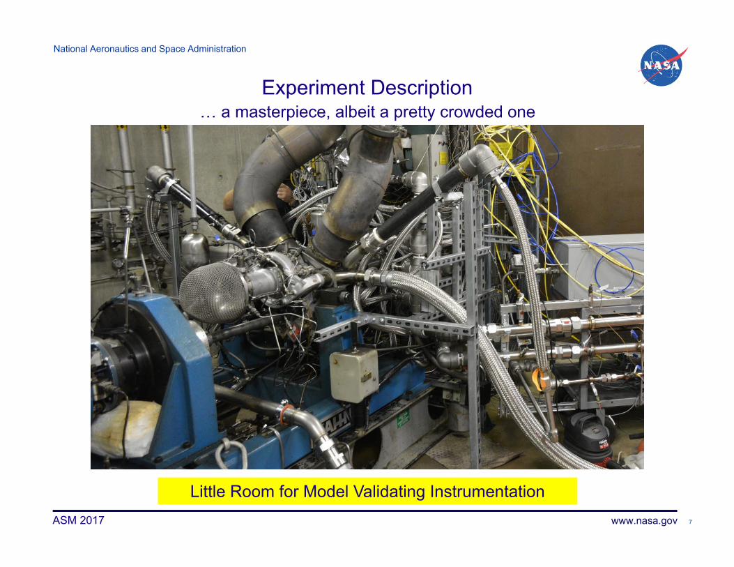
Experiment Description• Start with a small gas turbine
− T-63 (~3 lbm/s; ~6 OPR)
• Replace combustor with RDE & Ejector/ Bypass Configuration
pressuretransducerlocation
CL
RD
E ai
r
ejec
tor a
ir
ejec
tor a
irfu
el
Station 4, turbine inlet
mixingplane
RD
E c
hann
el
ejec
tor
• Vent compressor output− Compressor becomes HPT dynamometer
• Facility supply RDE & bypass• Add dynamometer to LPT
And the Result is…
National Aeronautics and Space Administration
www.nasa.govASM 2017 7
… a masterpiece, albeit a pretty crowded one
Little Room for Model Validating Instrumentation
Experiment Description

National Aeronautics and Space Administration
www.nasa.govASM 2017 8
Model Approach
• Solve RDE flowfield with 2-D CFD• Combine RDE exit flow with ejector/bypass flow using constant area mixing equations
• Accelerate flow to Station 4 using isentropic area change relations
• Static pressure at Station 4 is the only local measurement
pressuretransducerlocation
CL
RD
E ai
r
ejec
tor a
ir
ejec
tor a
irfu
el
Station 4, turbine inlet
mixingplane
RD
E c
hann
el
ejec
tor

National Aeronautics and Space Administration
www.nasa.govASM 2017 9
2-Dimensional CFDEuler Solver With Source Terms
• Calorically Perfect Gas• Source Terms Model:
• Chemical Reaction• Friction• Heat Transfer
• 2 Species Reaction (reactant or product)• Simplified Finite Rate Reaction• High Resolution Numerical Scheme• Coarse Numerical Grid (< 10,000 cells)• Adopts Detonation Frame of Reference
• Time derivatives ultimately vanish and solution is steady• Robust Boundary Conditions
• Sub or supersonic exhaust flow• Optional isentropic exhaust throat• Forward or reverse inlet flow with choking possible• Physics based inlet loss model from typical restriction
• Runs on a laptop• Approximately 20 sec. per wave revolution
Model Approach
9
Validated: Compares Well With Instrumented RDE Experiments(Thrust, Mass Flow Rate, Pressures)
National Aeronautics and Space Administration
www.nasa.govASM 2017 10
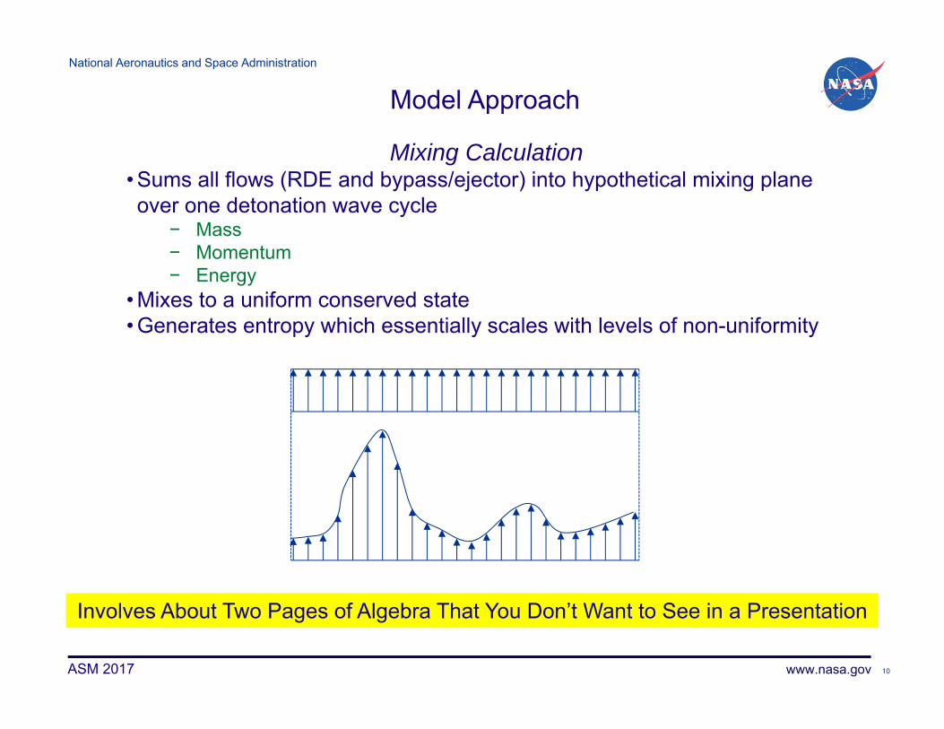
Involves About Two Pages of Algebra That You Don’t Want to See in a Presentation
Mixing Calculation• Sums all flows (RDE and bypass/ejector) into hypothetical mixing plane over one detonation wave cycle
− Mass− Momentum− Energy
• Mixes to a uniform conserved state• Generates entropy which essentially scales with levels of non-uniformity
Model Approach

National Aeronautics and Space Administration
www.nasa.govASM 2017 11
Closure
• Both RDE solver and mixing calculation require a specified pressure here – pexit
• We only know pressure here – p4Procedure
1. Guess pexit2. Adjust RDE inlet area until mass flow rate
matches experiment− Measured inlet manifold P, and T imposed
3. Mix RDE and ejector flows4. Accelerate Mixed flow through area
change5. Compare computed p4 with measured
value6. Repeat steps 1-5 until a match is found
Validation• Compare calculated and measured inlet areas
pressuretransducerlocation
CL
RD
E ai
r
ejec
tor a
ir
ejec
tor a
irfu
el
Station 4, turbine inlet
mixingplane
RD
E c
hann
el
ejec
tor
Acalc/Ameas≈0.71 for 2 Operating Points-Reasonable Considering Actual Flowpath and Model Simplicity
National Aeronautics and Space Administration
www.nasa.govASM 2017 12
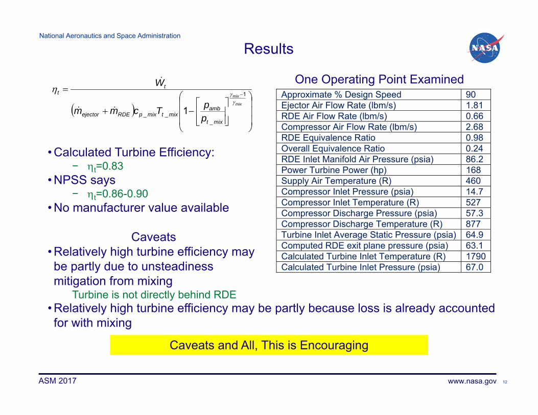
Results
• Calculated Turbine Efficiency:− t=0.83
• NPSS says− t=0.86-0.90
• No manufacturer value available
Caveats• Relatively high turbine efficiency may be partly due to unsteadiness mitigation from mixing
Turbine is not directly behind RDE
One Operating Point ExaminedApproximate % Design Speed 90 Ejector Air Flow Rate (lbm/s) 1.81 RDE Air Flow Rate (lbm/s) 0.66 Compressor Air Flow Rate (lbm/s) 2.68 RDE Equivalence Ratio 0.98 Overall Equivalence Ratio 0.24 RDE Inlet Manifold Air Pressure (psia) 86.2 Power Turbine Power (hp) 168 Supply Air Temperature (R) 460 Compressor Inlet Pressure (psia) 14.7 Compressor Inlet Temperature (R) 527 Compressor Discharge Pressure (psia) 57.3 Compressor Discharge Temperature (R) 877 Turbine Inlet Average Static Pressure (psia) 64.9 Computed RDE exit plane pressure (psia) 63.1 Calculated Turbine Inlet Temperature (R) 1790Calculated Turbine Inlet Pressure (psia) 67.0
mix
mix
mixt
ambmixtmixpRDEejector
tt
ppTcmm
W
1
___ 1
• Relatively high turbine efficiency may be partly because loss is already accounted for with mixing
Caveats and All, This is Encouraging

National Aeronautics and Space Administration
www.nasa.gov
4.60
4.85
5.10
5.35
5.60
5.85
6.10
-0.2
0
0.2
0.4
0.6
0.8
1
0.00 0.05 0.10
Tem
pera
ture
, T/T
*
Axi
al M
ach
Num
ber
Time, msec.
MachT/T*
ASM 2017 13
Results
Contours of Temperature
-2
-1.5
-1
-0.5
0
0.5
1
0.00 0.05 0.10
Nor
mai
lized
Mas
s Flu
x
Time, msec.
Observations• RDE is longer than necessary
− Adds to viscous losses− 28% of chemical energy sent to
walls• Exit flow is entirely subsonic and has inflow
• Inlet shows a relatively low backflow of 18% of total, but a large total pressure loss of 43% relative to manifold.
• Overall RDE pressure ratio=0.83− Not a pressure gain device− Though detonation itself has
PR=1.46
Perhaps We Can Do Better
National Aeronautics and Space Administration
www.nasa.govASM 2017 14
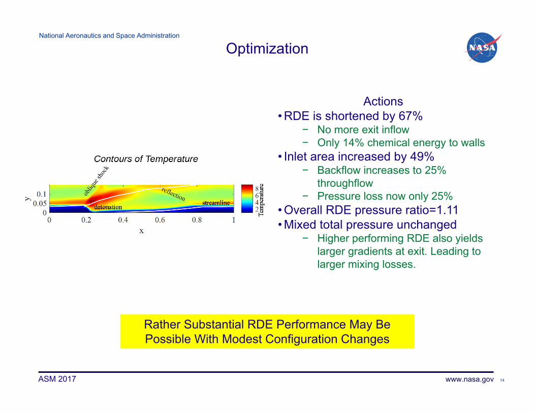
Optimization
Contours of Temperature
Actions• RDE is shortened by 67%
− No more exit inflow− Only 14% chemical energy to walls
• Inlet area increased by 49%− Backflow increases to 25%
throughflow− Pressure loss now only 25%
• Overall RDE pressure ratio=1.11• Mixed total pressure unchanged
− Higher performing RDE also yields larger gradients at exit. Leading to larger mixing losses.
Rather Substantial RDE Performance May Be Possible With Modest Configuration Changes

National Aeronautics and Space Administration
www.nasa.govASM 2017 15
Conclusion• Results from an experimental rig consisting of a rotating
detonation engine (RDE) with bypass ejector flow coupled to a downstream turbine were analyzed using a validated computational fluid dynamics RDE simulation combined with an algebraic mixing model of the ejector.
• The analysis agreed reasonably well with limited available data.
• The analysis indicated only modest loss of turbine efficiency compared to that under steady loading
• The examination indicated that the RDE operated in an unusual fashion, with subsonic flow throughout the exhaust plane.
• The rotating detonation produced a total pressure rise relative to the pre-detonative pressure; however, the length of the device and the substantial flow restriction at the inlet yielded an overall pressure loss.
• It was shown that with changes to the RDE length and inlet area the RDE could produce an overall pressure rise.
National Aeronautics and Space Administration
www.nasa.govASM 2017 16
AcknowledgmentNASA’s contribution to this work was done under a cooperative Reimbursable Space Act Agreement with the Air Force Research Laboratory in Dayton, Ohio.
National Aeronautics and Space Administration
www.nasa.govASM 2017 17
END