Embed Size (px)
Citation preview
Numerical analysis of the process of trapezoidal thread rolling
L. Kukielka & K. Kukielka
Abstract
In this paper the physical and mathematical models of deformations (displacements and strains) and stress in the cold process of trapezoidal thread rolling is presented. The process is considered as a geometrical and physical non-linear, initial as well as boundary value problem. The phenomena on a typical incremental step were described using a step-by-step incremental procedure, with an updated Lagrangian formulation. The state of strains was described by Green-Lagrange’s tensor, while the state of stress by the second symmetrical Pioli-Kirchhoff’s tensor. The object was treated as an elastic (in the reversible zone) and visco-plastic body (in non-reversible zone) with mixed hardening. The variational equation of motion in three dimensions for this case was proposed. Then, the finite elements methods (FEM) and dynamic explicit method (DEM) were used to obtain the solution. The application developed for the method of finite elements ANSYS 8.1 provides a complex time analysis of displacement, strains and stresses occurring in the object. The boundary conditions for a displacement increment determined in model investigations were used. Examples of calculations of influence of a friction coefficient on the state’s deformation and stress were presented.
1 Introduction
One of the most widespread machine elements is the thread. Above 60% parts of modern machines, devices and mechanism has threaded holes, whose performance by screw-tap in high-plastic steels, some non-ferrous metals and their alloy, pose difficult problems in technological aspects. The difficulty at threading hard materials characterized by a large ductility and a high elastic
High Performance Structures and Materials III 663
doi:10.2495/HPSM06065
The Technical University of Koszalin, Poland Department of Mechanical Engineering,
© 2006 WIT PressWIT Transactions on The Built Environment, Vol 85, www.witpress.com, ISSN 1743-3509 (on-line)
limit, come especially from the tendency to seizure the screw - tap in a threading hole. However, in spite of peck constructional improvements and many recommendations in the field of selection conditions for treatment quality executed, threads do not comply with standard technical requirements, the required proprieties do not apply to the surface layer, and apart from this, this tool wears away too fast, while the capacity of the process is low [1].
At the Technical University of Koszalin in Poland, in the Chair of Working Machines a scientific research is being conducted into methods of realization of male threads through plastic shaping (e.g. embossing screw threads) with a high velocity.
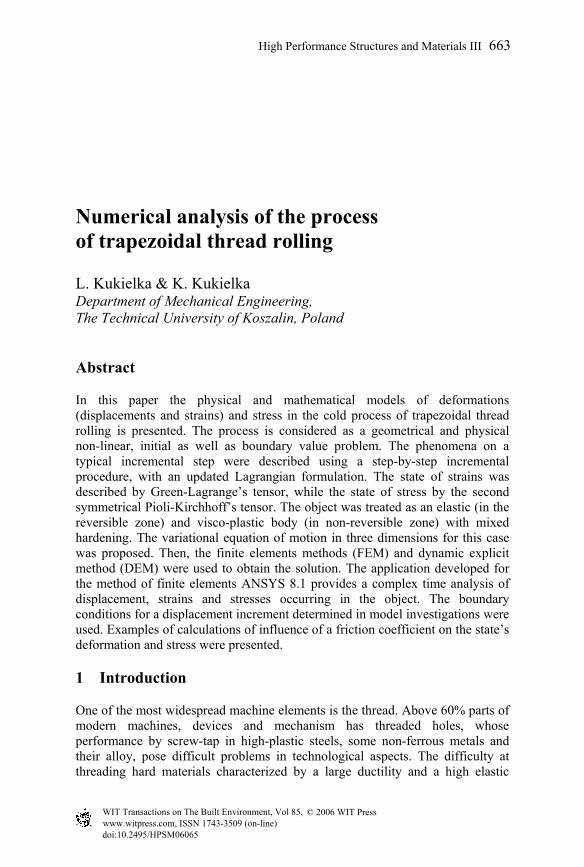
Thread rolling is a non-cutting cold-forming process, and this gives the following further advantages: the actual time for thread rolling lasts only seconds and, therefore, it is unimportant in respect to the cycle time; the time required for inspection is very short and the maintenance costs are extremely low; the rolling attachment operation is of a very high accuracy; changing to another thread size is possible by using another set of thread rolls and a gauge, provided that the thread diameter is in the range of the respective rolling attachment size; the short thread run-out (about ½ pitch) of the thread rolls allows to produce a thread reaching up to the collar of the component; high resistance to corrosion due to smooth press polished surfaces; significant in the surface strength; an uninterrupted grain flow (Fig. 1). The advantageous exploitation proprieties of screw threads are the result of a plastic strain in surface layer of elements.
Figure 1: The surface layer after trapezoidal thread rolling.
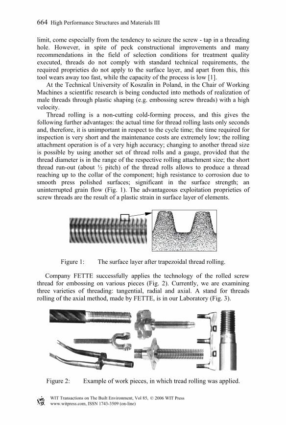
Company FETTE successfully applies the technology of the rolled screw thread for embossing on various pieces (Fig. 2). Currently, we are examining three varieties of threading: tangential, radial and axial. A stand for threads rolling of the axial method, made by FETTE, is in our Laboratory (Fig. 3).
Figure 2: Example of work pieces, in which tread rolling was applied.
664 High Performance Structures and Materials III
© 2006 WIT PressWIT Transactions on The Built Environment, Vol 85, www.witpress.com, ISSN 1743-3509 (on-line)
Figure 3: Machine for axial thread rolling, produced by the FETTE.
The trapezoidal thread rolling is a geometrical and physical non-linear process, with initial and boundary conditions as a function of time and space. The boundary conditions in the contact zone are not known. The paper has focused mostly on the preparation of a physical model of the process and then on a mathematical model and the solution algorithms obtained for the discrete systems of equations along with the respective initial and boundary conditions. The basic problem in this technology is the knowledge of physical phenomena, especially influence of friction coefficient on state’s deformation and stress in the surface layer.
2 Mathematical model of process
A mathematical model of the process is formulated in increments and contains the following: a material model, an equation of motion, with initial and boundary conditions.
2.1 Material model
2.1.1 Incremental model of yield stress Yield stress σy is the most important parameter characterizing the resistance of a visco-plastic deformation. The incremental model of the yield stress for a typical step time t→τ=t+∆t is defined as [2]:
,)(F][F][Fy)y(F )VP(eqt
)VP(eq
tt3
tt
sttt
1tt)VP(
eqt)VP(eq
tt
1tt
ttt2
ttyt ε∆ε
σ∂•∂
+ε∆ε∂
•∂+∆=σ∆ ττττ (1)
where /3∆e∆e2∆ε (VP)ij
τt
(VP)ij
τt
(VP)eq
τt = , /3e∆e∆2ε∆ (VP)
ijτt
(VP)ij
τt
(VP)eq
τt = are
the incremental of effective visco-plastic strain and strain rate; σst is the state stress depending on the accumulated effective visco-plastic strain and time,
y)y(F ttt2
tt ∆τ is the component of change in the initial yield stress Re with a
High Performance Structures and Materials III 665
© 2006 WIT PressWIT Transactions on The Built Environment, Vol 85, www.witpress.com, ISSN 1743-3509 (on-line)
change of chemical composition; (VP)eq
τt
(VP)eq
tt3
ttst
tt1
tt ∆ε)ε(F]σ]/[F[ ∂•∂ is the
component of change in the temporary yield stress ytt σ with change of the visco-
plastic strain, (VP)eq
τt
(VP)eq
tt1
tt ε∆]ε]/[F[ ∂•∂ is the component of change in the
temporary yield stress with change of the visco-plastic strain rate.
2.1.2 Elastic/visco-plastic material model A new model of mixed hardening for isotropic material which includes the combined effects of elasticity (a reversible domain), visco-plasticity (a non reversible domain) (E/VP) is used. The model takes into account the history of the material.
The constitutive equation of increment components of a total strain tensor takes form [3]:
A]∆σD[S~1
1∆ε ttkl
τt
(E)ijkl
tt**t
tij
τt −
−= (2)
and of increment components of the total stress tensor:
A],∆εCS~[S~ψ∆εC∆σ t
tklτt
(E)ijkl
ttij
tt
*ij
ttkl
τt
(E)ijkl
ttij
τt −−= (3)
where:
mntt
(TE)ijmn
tt
*ij
tt
**tt S~CS~S~ = (4)
is a positive scalar variable,
,)EC~(σS~CS~
S~S~
Ttt
tt
2y
ttij
tt
(E)ijkl
ttij
tt
ijtt*
ijtt
3
2++
= (5)
is a component of a stress tensor,
(VP)eq
τt(VP)
eqtt
yy
tt
tt ε∆
εσ
σA3
2
∂
∂= (6)
is a positive scalar variable, ijt σ∆τ is the increment component of the second
Piola-Kirchhoff stress tensor, (E)ijkl
tt D are the components of tensor
1(E)tt
(E)tt ]C[D −= in time t, ij
τt∆ε is the increment component of Green-Lagrange
strain tensor, (E)ijkl
t C are the components of elastic constitutive tensor.
666 High Performance Structures and Materials III
© 2006 WIT PressWIT Transactions on The Built Environment, Vol 85, www.witpress.com, ISSN 1743-3509 (on-line)
2.2 Incremental model of motion
In this section we develop the equation of a deformation of the object in the updated Lagrangian formulation. Assuming that numerical solutions are obtained at discrete time t, the solution for t+∆t is to be obtained. In such a case, a functional increment )(t ⋅∆τ J is formulated for the increment displacement and reads as follows:
)(∆)∆u,u∆,u∆(∆ τ
tiτti
τti
τt
τt ⋅= JJ , (7)
where ititit u,u,u ∆∆∆ τττ are the ith increment components of the displacement, velocity and acceleration vectors, respectively. While using the conditions of stationary of functional J∆τ
t and a finite element method, we can write an equation of motion in the form: }{}{}{}{}]){[]([}]{[}]{[ t
ttttttTtT
tttT
ttt
tt RFFRrKKrCrM ++∆+∆=∆∆++∆+∆ ττττττ (8)
where mass matrix ][t
t M , damping matrix ][ Ttt C , stiffness matrix ][ T
tt K and
force vector }{ Ttt F are known at time t. However, increment stiffness matrix
][ Tt K∆τ , external incremental load vector }{t R∆τ , internal incremental forces
vector }{t F∆τ , incremental vectors of displacement }{t r∆τ , velocity }{t r∆τ and
acceleration }{t r∆τ of finite element assembly at a typical step time are not known. In order to solve this problem we apply the integration methods.
3 DEM solution
Assuming that an increase of temporary step ∆t is very small, it is possible to execute a linearization of equation (8) and using the incremental decomposition we obtain: }.{}{}]{[}]{[}]{[ t
ttTtttt
tttT
tttT
ttt QFrKrCrM ∆−
∆−∆−∆−∆−∆− +=++ (9)
Then using the central difference method (DEM), in which it is assumed that: }){}({
t21}{ ttttt rrr ∆−∆+ −∆
= , }){}{2}({t1}{ ttttt
2t rrrr ∆−∆+ +−
∆= (10)
and substituting the relations in (10) into (9) we obtain:
High Performance Structures and Materials III 667
© 2006 WIT PressWIT Transactions on The Built Environment, Vol 85, www.witpress.com, ISSN 1743-3509 (on-line)
}~{}]{~[ Ttttt QrM ∆−
τ = , (11) where:
].[t2}{][
t}{}{2
}]{[}{}{}~{
],[t2
1][t1]~[
T
tt
2
ttt
tttT
tttT
ttttT
ttt
T2
CrMrr
rKQFQ
CMM
∆+
∆−
+
+−+=
∆+
∆=
∆−∆−∆−∆−
∆−∆−∆− (12)
The integration method requires that the time step ∆t is smaller than critical value ∆tkr, which can be calculated from the mass and stiffness properties of the complete element assemblage: ,/Ttt Nkr π=∆≤∆ where TN is the smallest period of the finite element assemblage with n degrees of freedom.
4 Model investigation
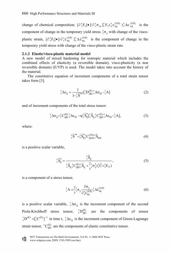
The model investigation was conducted in order to settle the course deformation layer top sample executed from the plastic material, as well as with the aim to qualify boundary conditions for displacements indispensable to numeric analysis of the trapezoidal tread rolling process. To model investigations were applied to the samples in a rectangle shape with the following dimensions:
Figure 4: The stamp (a) and the meshed sample before deformation (b).
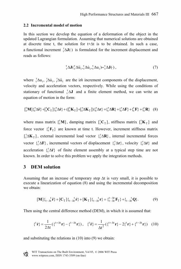
Two samples were joined by sides with a plot mesh, and were closed in a metal form. Then the samples were subjected to the deformation by a perpendicular shift of rectilinear motion in the model stamp of an outline of trapezoidal thread rolling. The view of the deformed mesh of complete elements is presented in Fig. 5.
Figure 5: The mesh after deformation for µ=0,2 (a) and µ=0,39 (b).
bb))aa))
bb))aa))
668 High Performance Structures and Materials III
© 2006 WIT PressWIT Transactions on The Built Environment, Vol 85, www.witpress.com, ISSN 1743-3509 (on-line)
5 Numerical analysis of state of displacement, strain and stress of material during trapezoidal thread rolling
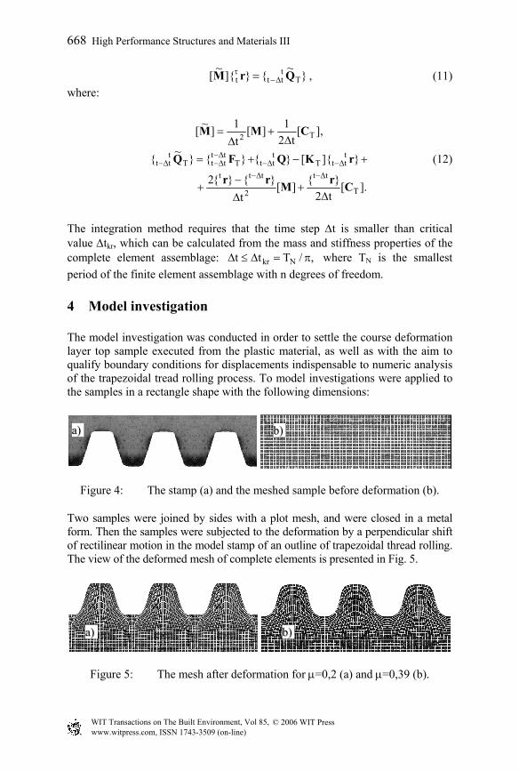
The application developed with regard to the method of finite elements in ANSYS 8.1 programme provides a complex time analysis of states of displacement, strains and stresses. Digital computing for the process was carried out with the use of two methods. The first method requires introducing the boundary conditions for displacements in the contact zone determined by the model investigation, whereas the second one requires the adequate determination of the contact zone without an introduction of boundary conditions. The main aim of the simulation was to define the influence of friction coefficient on the state of deformation and stress in the surface layer of the object. The numerical analysis for 2-D states of deformation and 3-D states of stress was applied on the example of steel C55 (DIN). The example results of deformation, strain and stress obtained by the numerical analysis for friction coefficient µ=0,2 and µ=0,39 are presented in Fig. 6 and Fig.7.
Figure 6: Composition of numerical results for friction coefficient µ=0,2: 1 – initial finite element mesh, 2 - finite elements after deformation, 3 – intensity of strain, 4 – intensity of stress.
The distribution of strain and stress intensity in defined nodes (Fig. 8) is shown in Figs. 9–12.
High Performance Structures and Materials III 669
© 2006 WIT PressWIT Transactions on The Built Environment, Vol 85, www.witpress.com, ISSN 1743-3509 (on-line)
1
X
Y
Z
APR 13 200521:59:14
ELEMENTS2
X
Y
Z
APR 13 200521:59:14
DISPLACEMENT
STEP=1SUB =100TIME=1DMX =15.6
3
MN
MX
X
Y
Z
.00995
.9114051.813
2.7143.616
APR 13 200521:59:14
NODAL SOLUTION
STEP=1SUB =100TIME=1EPTOINT (AVG)DMX =15.6SMN =.00995SMX =3.616
4
MN
MX
X
Y
Z
.517E+08
.485E+09.918E+09
.135E+10.178E+10
APR 13 200521:59:14
NODAL SOLUTION
STEP=1SUB =100TIME=1SINT (AVG)DMX =15.6SMN =.517E+08SMX =.178E+10
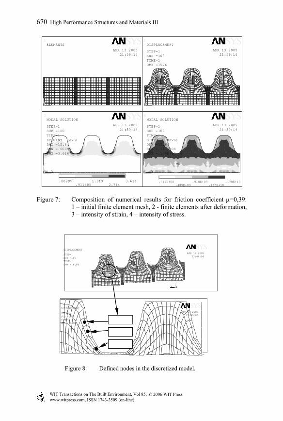
Figure 7: Composition of numerical results for friction coefficient µ=0,39: 1 – initial finite element mesh, 2 - finite elements after deformation, 3 – intensity of strain, 4 – intensity of stress.
1
X
Y
Z
APR 19 200522:49:06
DISPLACEMENT
STEP=1SUB =100TIME=1DMX =16.85
2
APR 19 200522:49:06
DISPLACEMENT
STEP=1SUB =100TIME=1DMX =16.85
Figure 8: Defined nodes in the discretized model.
node 158
node 160
node 127
670 High Performance Structures and Materials III
© 2006 WIT PressWIT Transactions on The Built Environment, Vol 85, www.witpress.com, ISSN 1743-3509 (on-line)
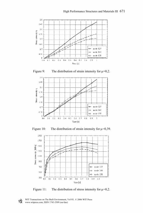
Figure 9: The distribution of strain intensity for µ=0,2.
Figure 10: The distribution of strain intensity for µ=0,39.
Figure 11: The distribution of stress intensity for µ=0,2.
High Performance Structures and Materials III 671
© 2006 WIT PressWIT Transactions on The Built Environment, Vol 85, www.witpress.com, ISSN 1743-3509 (on-line)
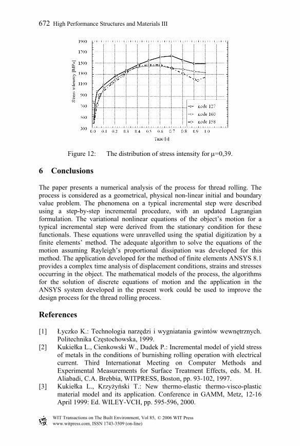
Figure 12: The distribution of stress intensity for µ=0,39.
6 Conclusions
The paper presents a numerical analysis of the process for thread rolling. The process is considered as a geometrical, physical non-linear initial and boundary value problem. The phenomena on a typical incremental step were described using a step-by-step incremental procedure, with an updated Lagrangian formulation. The variational nonlinear equations of the object’s motion for a typical incremental step were derived from the stationary condition for these functionals. These equations were unravelled using the spatial digitization by a finite elements’ method. The adequate algorithm to solve the equations of the motion assuming Rayleigh’s proportional dissipation was developed for this method. The application developed for the method of finite elements ANSYS 8.1 provides a complex time analysis of displacement conditions, strains and stresses occurring in the object. The mathematical models of the process, the algorithms for the solution of discrete equations of motion and the application in the ANSYS system developed in the present work could be used to improve the design process for the thread rolling process.
References
[1] Łyczko K.: Technologia narzędzi i wygniatania gwintów wewnętrznych. Politechnika Częstochowska, 1999.
[2] Kukiełka L., Cienkowski W., Dudek P.: Incremental model of yield stress of metals in the conditions of burnishing rolling operation with electrical current. Third Internationat Meeting on Computer Methods and Experimental Measurements for Surface Treatment Effects, eds. M. H. Aliabadi, C.A. Brebbia, WITPRESS, Boston, pp. 93-102, 1997.
[3] Kukiełka L., Krzyżyński T.: New thermo-elastic thermo-visco-plastic material model and its application. Conference in GAMM, Metz, 12-16 April 1999: Ed. WILEY-VCH, pp. 595-596, 2000.
672 High Performance Structures and Materials III
© 2006 WIT PressWIT Transactions on The Built Environment, Vol 85, www.witpress.com, ISSN 1743-3509 (on-line)