Embed Size (px)
Citation preview
2012 SIMULIA Community Conference 1
Numerical analyses of low velocity impacts on composite. Advanced modelling techniques.
Giovanni Perillo1, Nils Petter Vedvik
1, Andreas T. Echtermeyer
1
1 Norwegian University of Science and Technology (NTNU) - Department of Engineering Design
and Materials
Abstract: Due to the extreme increase in computational power over the last years, numerical
analyses are gaining more success in designing composite structures and components, taking into consideration complicated failure mechanisms. One crucial aspect is low velocity impact. It can produce devastating damage that can lead to premature failure of the component/structure.
However, modelling the three-dimensional impact damage and its consequences is still a challenge. This is because material properties, failure criteria, properties after initial failure, and numerical techniques are still not well established, especially for the through thickness properties.
As a consequence, industry must perform costly full-scale tests to improve the design and eventually to prove its fitness for purpose. In this paper the most advanced features currently
available in FE analysis (Abaqus/Explicit) have been used to predict the behaviour of a composite structure under low velocity impact. A low velocity impact event on a flat composite plate has been evaluated. The plate has been modelled using solid elements for each composite layer and a
user defined material model with a modified Puck failure criterion was implemented. The intralayer damages (fibre breaking, matrix failure) are evaluated. Between each layer, cohesive elements have been placed to model the interlayer damage (delamination). Failure initiation and
properties of damaged/degraded materials are modelled. The influences of the different parameters, mesh dimensions, element types and failure criteria on the numerical results are reported. The numerical results have been compared with real experimental data from literature.
Keywords: Composites, Damage, Delamination, Failure, Fracture, Impact
1. Introduction
Fibre composite materials are widely used in a variety of structural applications. The low weight (compare to the classical structural materials like steel, aluminium etc.) combined with good
strength and stiffness make it the optimum in many structural applications. Though these materials have very attractive properties, their use is often restricted due to their vulnerability to the
transverse impact (Abrate 1998) leading to the necessity of a higher safety factor resulting in an increase of the total weight.
The damage produced by low velocity impact can be divided in two different categories: intralayer
damages: mainly matrix cracking and fibre breaking, along with interlayer damage (delamination) that occurs between different oriented plies. Perforation is another possible damage that occurs especially in case of a high energy/velocity impact event which is not considered in this work.
This work mainly focuses on the study of delamination and matrix cracks that are the primary damage events that occur during impact at low velocity/energy. These damages are difficult to
detect but deserve high attention due to the reduction of the resultant compressive strength.
2 2012 SIMULIA Community Conference
The impact response of composites has been investigated in depth in past years especially by experimental works and analytical/numerical formulation (Zhou 1998; Naik NK 2000; Olsson 2001). A huge effort has been used for the implementation of an analytical closed (Abrate 2001;
Olsson 2001; Olsson 2006) and semi-closed (Gong SW 1994; Gong SW 1995) form solution that unfortunately are only applicable to very simple impact cases. These analytical methods are based
on mathematical and physical principles and provide a better understanding of the controlling factors but are unsuitable for predicting the impact-induced damages like delamination and matrix cracking. Experimental studies are fundamental for the verification of the theoretical predictions
but are too expensive when the experimental parameters need to be varied over a wide range. Today, due to the current computational power and the new available technologies, the Finite Element Methods (FE) can be used to simulate the impact event in composites.
1.1 Scope
The present work is a Finite Elements (FE) investigation on impact problems on laminated
composites using the most advanced modelling technique currently available. The FE commercial software, Abaqus/Cae and Abaqus/Explicit, has been used to model and analyze the impact events. This work gives an overview of the newest available numerical technique applied to model the
impact on laminated composites. Both interlayer and intralayer damages have been considered for the numerical simulation. The intralayer damages have been evaluated using: Puck failure criterion (Puck and Schürmann 1998; Puck and Schürmann 2001) for matrix cracking and Hashin
failure criterion (Hashin 1980) for fibre failure, implemented by a user defined material model VUMAT written in Fortran. The interlayer damage has been evaluated by the use of the CZM
(cohesive zone model) and was implemented by the standard cohesive elements available in Abaqus.
2. Failure modes in low velocity impact
In the present work only low velocity impact events have been considered; with no complete penetration of the target by the impactor. For this type of impact, the main damage modes were:
delamination and matrix cracking; fibre failure rarely occurred. The impact damage starts with localized matrix cracking that acts as an initiation point for propagation of delamination. Two types of matrix cracks can be observed: vertical and oblique cracks (Figure 1). Vertical cracks are
introduced by the flexural deformations due to the tensile stresses and are generally located at the bottom plies. Oblique cracks (related to the layer plane) are formed by the high transverse shear
stresses due to the flexural deformation of the component. These cracks are typically located at the top or middle plies. Even if the matrix cracks do not significantly reduce the laminate properties, they work as delamination initiation point. Delamination occurs at the interface between the
different oriented layers and is introduced by interlaminar shear stresses which are promoted due to: matrix cracking, different stiffness between the adjacent plies, and deflection of the structure. The usual shape is an oblong peanut with the mayor axis oriented in the fibre direction of the
lower layer (Abrate 1998; Davies 2004). The peanut shape is a result of the shear stress distribution around the impactor, the interlamina shear strength along the fibre direction and the
matrix cracking. Figure 2 shows the typical delamination shape for [90/-45/0/-45] laminate.

2012 SIMULIA Community Conference 3
Figure 1: Type of matrix cracks in a [0/90/0] laminated composite (longitudinal and transverse views).
Figure 2: Shape of the delamination
2.1 Intralayer damage material model – VUMAT
A user defined material model with the intralayer damage model for laminated composite material has been implemented for Abaqus/Explicit by a VUMAT subroutine. The intralayer failure modes
of composites were evaluated using Puck failure criterion (Puck and Schürmann 1998; Puck and Schürmann 2001) for matrix cracking, and the classical Hashin failure criterion (Hashin 1980) for fibre failure. When failure was predicted in a particular position of the composite, the local
properties were reduced according to the failure type. The subroutine was implemented to be used with both brick and tetrahedral elements.
Hashin failure criterion for fibre failure
The Hashin failure criterion (Hashin 1980) for fibre failure is reported here:
(1)
4 2012 SIMULIA Community Conference
Where is the stress in the fibre direction and and are the in plane and the out of plane shear stresses. Moreover and are the tension and compression strengths in the fibre
directions and is the in plane shear strength of the used material.
Puck failure criteria
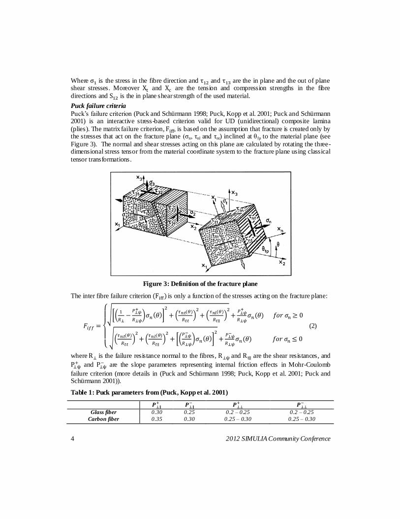
Puck’s failure criterion (Puck and Schürmann 1998; Puck, Kopp et al. 2001; Puck and Schürmann 2001) is an interactive stress-based criterion valid for UD (unidirectional) composite lamina
(plies). The matrix failure criterion, , is based on the assumption that fracture is created only by the stresses that act on the fracture plane (σn, τnl and τnt) inclined at θfp to the material plane (see
Figure 3). The normal and shear stresses acting on this plane are calculated by rotating the three-dimensional stress tensor from the material coordinate system to the fracture plane using classical
tensor transformations.
Figure 3: Definition of the fracture plane
The inter fibre failure criterion is only a function of the stresses acting on the fracture plane:
(2)
where is the failure resistance normal to the fibres, and are the shear resistances, and
and
are the slope parameters representing internal friction effects in Mohr-Coulomb
failure criterion (more details in (Puck and Schürmann 1998; Puck, Kopp et al. 2001; Puck and Schürmann 2001)).
Table 1: Puck parameters from (Puck, Kopp et al. 2001)
Glass fiber 0.30 0.25 0.2 – 0.25 0.2 – 0.25
Carbon fiber 0.35 0.30 0.25 – 0.30 0.25 – 0.30
2012 SIMULIA Community Conference 5
The parameters presented before can be calculated (Puck, Kopp et al. 2001) using:
(3)
Where and are the tension and compression in plane material strengths in the direction perpendicular to the fibre. In addition to the standard material parameters, special Puck parameters are needed. Measuring these parameters requires complicated multi-axial testing. However, Puck recommends using the default parameters given in the Table 1.
2.2 Interlayer damage – Cohesive zone model (CZM)
The interlayer damage (delamination) was implemented by the cohesive zone model. This model is based on the assumption that between the different composite layers there is another material with an own constitutive law. This interface connects the different structural elements (layers) and
is mainly based on the cohesive crack model introduced by (Dugdale 1960; Barenblatt 1962; Hillerborg 1976). This theory is based on a presence of a cohesive damage zone near the crack
front that connects the tractions to displacement jumps at the interface where the crack may occur. The damage initiation is directly connected to the interfacial strength of the material and the damage evolution is related to the critical strain energy release rates. When the total area under the
traction-separation curve is equal to the critical fracture toughness of the interface material, the residual traction force is reduced to zero. The main advantage of this theory is related to the possibility to have both the crack initiation and propagation in the same model, thus reducing the
complexity of the numerical model. The critical problem with CZM is related to the crack path that needs to be known in advance. Only in these cases can discrete interface elements (with
cohesive law) be inserted in the finite element mesh. For composite materials, the crack path definition is not a problem due to the nature of the material that allows delamination only between the different oriented plies. The crack can be easily defined a priori.
Constitutive response / damage model for cohesive elements
The cohesive elements used in the present work are those implemented in Abaqus/Explicit based on the (Dugdale 1960; Barenblatt 1962; Hillerborg 1976) theory. Cohesive behavior is defined
directly in terms of a traction-separation law based on the follow assumptions:
Linear elastic traction-separation law for the undamaged material;
Damage onset based on stress criterion
Material degradation based on fracture mechanic More details about the cohesive elements can be founded in the Abaqus Analysis User Manual.
6 2012 SIMULIA Community Conference
3. Numerical modelling
Composite
The laminate was modelled using the most advanced techniques currently available in Abaqus.
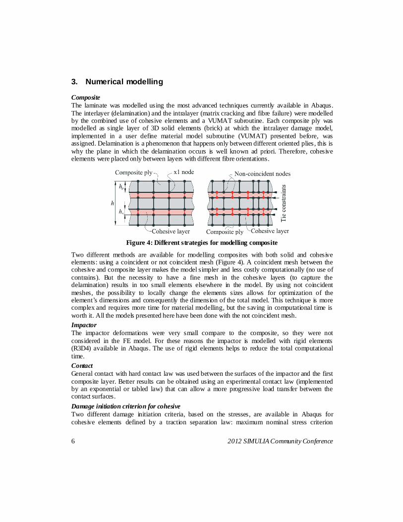
The interlayer (delamination) and the intralayer (matrix cracking and fibre failure) were modelled by the combined use of cohesive elements and a VUMAT subroutine. Each composite ply was modelled as single layer of 3D solid elements (brick) at which the intralayer damage model,
implemented in a user define material model subroutine (VUMAT) presented before, was assigned. Delamination is a phenomenon that happens only between different oriented plies , this is
why the plane in which the delamination occurs is well known ad priori. Therefore, cohesive elements were placed only between layers with different fibre orientations.
Figure 4: Different strategies for modelling composite
Two different methods are available for modelling composites with both solid and cohesive elements: using a coincident or not coincident mesh (Figure 4). A coincident mesh between the cohesive and composite layer makes the model simpler and less costly computationally (no use of
contrains). But the necessity to have a fine mesh in the cohesive layers (to capture the delamination) results in too small elements elsewhere in the model. By using not coincident
meshes, the possibility to locally change the elements sizes allows for optimization of the element’s dimensions and consequently the dimension of the total model. This technique is more complex and requires more time for material modelling, but the saving in computational time is
worth it. All the models presented here have been done with the not coincident mesh.
Impactor
The impactor deformations were very small compare to the composite, so they were not
considered in the FE model. For these reasons the impactor is modelled with rigid elements (R3D4) available in Abaqus. The use of rigid elements helps to reduce the total computational
time.
Contact
General contact with hard contact law was used between the surfaces of the impactor and the first
composite layer. Better results can be obtained using an experimental contact law (implemented by an exponential or tabled law) that can allow a more progressive load transfer between the contact surfaces.
Damage initiation criterion for cohesive
Two different damage initiation criteria, based on the stresses, are available in Abaqus for
cohesive elements defined by a traction separation law: maximum nominal stress criterion
2012 SIMULIA Community Conference 7
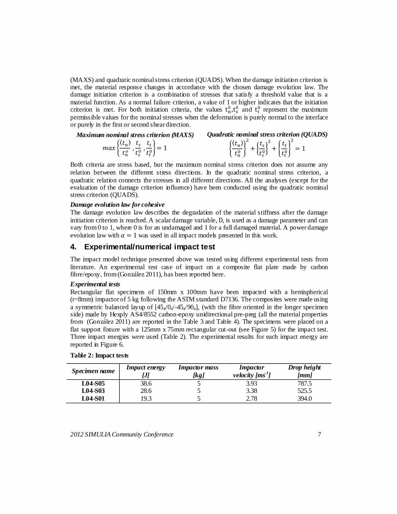
(MAXS) and quadratic nominal stress criterion (QUADS). When the damage initiation criterion is met, the material response changes in accordance with the chosen damage evolution law. The damage initiation criterion is a combination of stresses that satisfy a threshold value that is a
material function. As a normal failure criterion, a value of 1 or higher indicates that the initiation criterion is met. For both initiation criteria, the values
and
represent the maximum
permissible values for the nominal stresses when the deformation is purely normal to the interface or purely in the first or second shear direction.
Maximum nominal stress criterion (MAXS)
Quadratic nominal stress criterion (QUADS)
Both criteria are stress based, but the maximum nominal stress criterion does not assume any
relation between the different stress directions. In the quadratic nominal stress criterion, a
quadratic relation connects the stresses in all different directions. All the analyses (except for the evaluation of the damage criterion influence) have been conducted using the quadratic nominal stress criterion (QUADS).
Damage evolution law for cohesive
The damage evolution law describes the degradation of the material stiffness after the damage
initiation criterion is reached. A scalar damage variable, , is used as a damage parameter and can vary from 0 to 1, where 0 is for an undamaged and 1 for a full damaged material. A power damage
evolution law with was used in all impact models presented in this work.
4. Experimental/numerical impact test
The impact model technique presented above was tested using different experimental tests from
literature. An experimental test case of impact on a composite flat plate made by carbon fibre/epoxy, from (González 2011), has been reported here.
Experimental tests
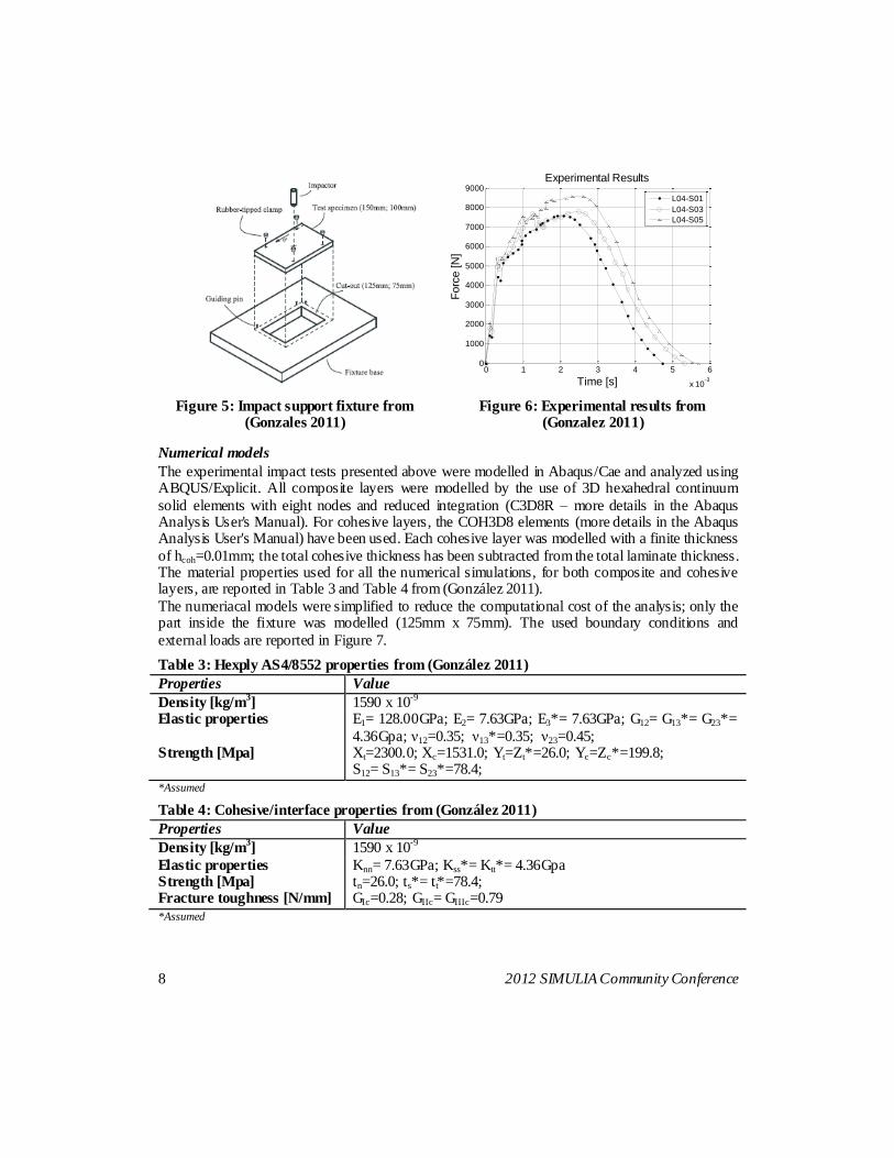
Rectangular flat specimens of 150mm x 100mm have been impacted with a hemispherical (r=8mm) impactor of 5 kg following the ASTM standard D7136. The composites were made using
a symmetric balanced layup of [454/04/-454/904]s (with the fibre oriented in the longer specimen side) made by Hexply AS4/8552 carbon-epoxy unidirectional pre-preg (all the material properties from (González 2011) are reported in the Table 3 and Table 4). The specimens were placed on a
flat support fixture with a 125mm x 75mm rectangular cut-out (see Figure 5) for the impact test. Three impact energies were used (Table 2). The experimental results for each impact energy are
reported in Figure 6.
Table 2: Impact tests
Specimen name Impact energy
[J]
Impactor mass
[kg]
Impactor
velocity [ms-1
]
Drop height
[mm]
L04-S05 38.6 5 3.93 787.5 L04-S03 28.6 5 3.38 525.5
L04-S01 19.3 5 2.78 394.0
8 2012 SIMULIA Community Conference
Figure 5: Impact support fixture from (Gonzales 2011)
Figure 6: Experimental results from (Gonzalez 2011)
Numerical models
The experimental impact tests presented above were modelled in Abaqus/Cae and analyzed using ABQUS/Explicit. All composite layers were modelled by the use of 3D hexahedral continuum
solid elements with eight nodes and reduced integration (C3D8R – more details in the Abaqus Analysis User's Manual). For cohesive layers, the COH3D8 elements (more details in the Abaqus Analysis User's Manual) have been used. Each cohesive layer was modelled with a finite thickness
of hcoh=0.01mm; the total cohesive thickness has been subtracted from the total laminate thickness. The material properties used for all the numerical simulations, for both composite and cohesive layers, are reported in Table 3 and Table 4 from (González 2011).
The numeriacal models were simplified to reduce the computational cost of the analysis; only the part inside the fixture was modelled (125mm x 75mm). The used boundary conditions and
external loads are reported in Figure 7.
Table 3: Hexply AS4/8552 properties from (González 2011)
Properties Value
Density [kg/m3] 1590 x 10
-9
Elastic properties E1= 128.00GPa; E2= 7.63GPa; E3*= 7.63GPa; G12= G13*= G23*=
4.36Gpa; ν12=0.35; ν13*=0.35; ν23=0.45; Strength [Mpa] Xt=2300.0; Xc=1531.0; Yt=Zt*=26.0; Yc=Zc*=199.8;
S12= S13*= S23*=78.4;
*Assumed
Table 4: Cohesive/interface properties from (González 2011)
Properties Value
Density [kg/m3] 1590 x 10
-9
Elastic properties Knn= 7.63GPa; Kss*= Ktt*= 4.36Gpa Strength [Mpa] tn=26.0; ts*= tt*=78.4; Fracture toughness [N/mm] GIc=0.28; GIIc= GIIIc=0.79
*Assumed
0 1 2 3 4 5 6
x 10-3
0
1000
2000
3000
4000
5000
6000
7000
8000
9000
Time [s]
Forc
e [N
]
Experimental Results
L04-S01
L04-S03
L04-S05
2012 SIMULIA Community Conference 9
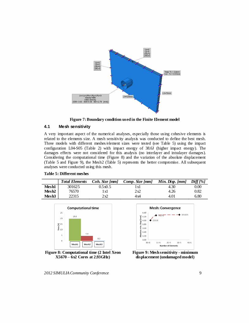
Figure 7: Boundary condition used in the Finite Element model
4.1 Mesh sensitivity
A very important aspect of the numerical analyses, especially those using cohesive elements is
related to the elements size. A mesh sensitivity analysis was conducted to define the best mesh. Three models with different meshes/element sizes were tested (see Table 5) using the impact
configuration L04-S05 (Table 2) with impact energy of 38.6J (higher impact energy). The damages effects were not considered for this analysis (no interlayer and intralayer damages). Considering the computational time (Figure 8) and the variation of the absolute displacement
(Table 5 and Figure 9), the Mesh2 (Table 5) represents the better compromise. All subsequent analyses were conducted using this mesh.
Table 5: Different meshes
Total Elements Coh. Size [mm] Comp. Size [mm] Min. Disp. [mm] Diff [%]
Mesh1 301625 0.5x0.5 1x1 4.30 0.00 Mesh2 76570 1x1 2x2 4.26 0.82
Mesh3 22315 2x2 4x4 4.01 6.80
Figure 8: Computational time (2 Intel Xeon
X5670 – 6x2 Cores at 2.93GHz)
Figure 9: Mesh sensitivity - minimum
displacement (undamaged model)
10 2012 SIMULIA Community Conference
4.2 Different impact energies
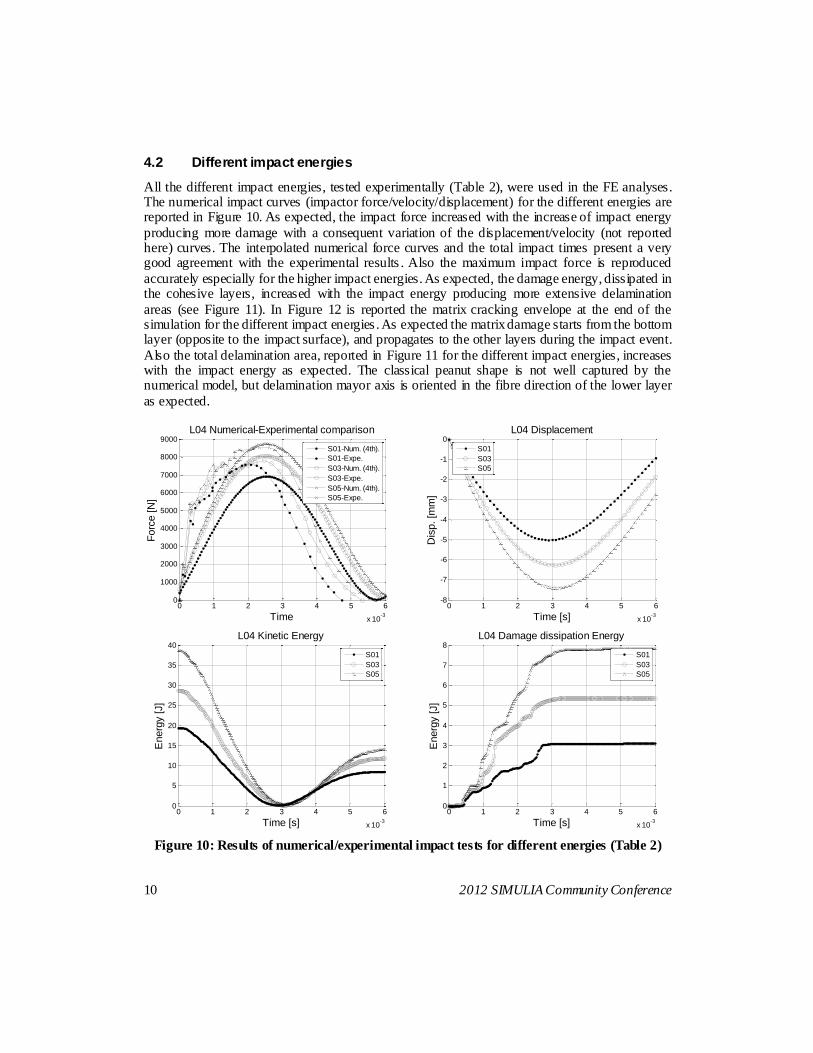
All the different impact energies, tested experimentally (Table 2), were used in the FE analyses. The numerical impact curves (impactor force/velocity/displacement) for the different energies are reported in Figure 10. As expected, the impact force increased with the increase of impact energy
producing more damage with a consequent variation of the displacement/velocity (not reported here) curves. The interpolated numerical force curves and the total impact times present a very good agreement with the experimental results . Also the maximum impact force is reproduced
accurately especially for the higher impact energies. As expected, the damage energy, dissipated in the cohesive layers, increased with the impact energy producing more extensive delamination
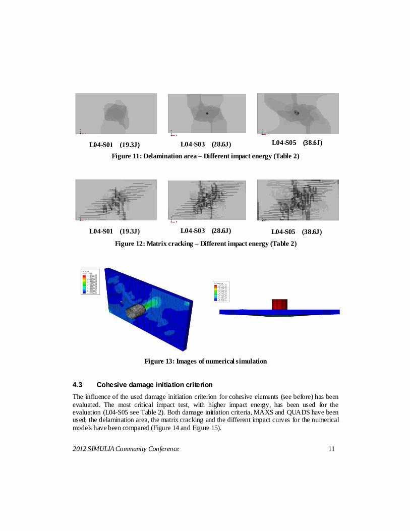
areas (see Figure 11). In Figure 12 is reported the matrix cracking envelope at the end of the simulation for the different impact energies . As expected the matrix damage starts from the bottom layer (opposite to the impact surface), and propagates to the other layers during the impact event.
Also the total delamination area, reported in Figure 11 for the different impact energies, increases with the impact energy as expected. The classical peanut shape is not well captured by the numerical model, but delamination mayor axis is oriented in the fibre direction of the lower layer
as expected.
Figure 10: Results of numerical/experimental impact tests for different energies (Table 2)
0 1 2 3 4 5 6
x 10-3
0
1000
2000
3000
4000
5000
6000
7000
8000
9000
Time
Forc
e [N
]
L04 Numerical-Experimental comparison
S01-Num. (4th).
S01-Expe.
S03-Num. (4th).
S03-Expe.
S05-Num. (4th).
S05-Expe.
0 1 2 3 4 5 6
x 10-3
-8
-7
-6
-5
-4
-3
-2
-1
0
Time [s]
Dis
p. [m
m]
L04 Displacement
S01
S03
S05
0 1 2 3 4 5 6
x 10-3
0
5
10
15
20
25
30
35
40
Time [s]
Energ
y [J]
L04 Kinetic Energy
S01
S03
S05
0 1 2 3 4 5 6
x 10-3
0
1
2
3
4
5
6
7
8
Time [s]
Energ
y [J]
L04 Damage dissipation Energy
S01
S03
S05
2012 SIMULIA Community Conference 11
L04-S01 (19.3J) L04-S03 (28.6J) L04-S05 (38.6J)
Figure 11: Delamination area – Different impact energy (Table 2)
L04-S01 (19.3J) L04-S03 (28.6J)
L04-S05 (38.6J)
Figure 12: Matrix cracking – Different impact energy (Table 2)
Figure 13: Images of numerical simulation
4.3 Cohesive damage initiation criterion
The influence of the used damage initiation criterion for cohesive elements (see before) has been
evaluated. The most critical impact test, with higher impact energy, has been used for the evaluation (L04-S05 see Table 2). Both damage initiation criteria, MAXS and QUADS have been used; the delamination area, the matrix cracking and the different impact curves for the numerical
models have been compared (Figure 14 and Figure 15).
12 2012 SIMULIA Community Conference
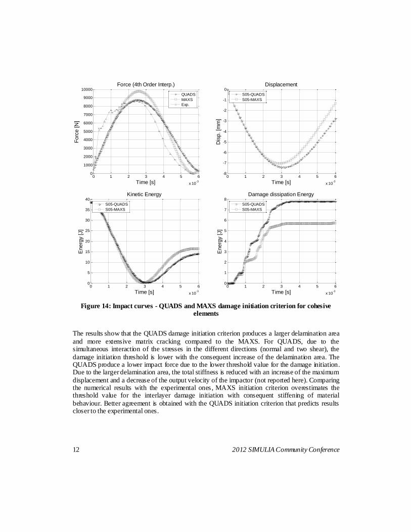
Figure 14: Impact curves - QUADS and MAXS damage initiation criterion for cohesive elements
The results show that the QUADS damage initiation criterion produces a larger delamination area
and more extensive matrix cracking compared to the MAXS. For QUADS, due to the simultaneous interaction of the stresses in the different directions (normal and two shear), the
damage initiation threshold is lower with the consequent increase of the delamination area. The QUADS produce a lower impact force due to the lower threshold value for the damage initiation. Due to the larger delamination area, the total stiffness is reduced with an increase of the maximum
displacement and a decrease of the output velocity of the impactor (not reported here). Comparing the numerical results with the experimental ones , MAXS initiation criterion overestimates the threshold value for the interlayer damage initiation with consequent stiffening of material
behaviour. Better agreement is obtained with the QUADS initiation criterion that predicts results closer to the experimental ones.
0 1 2 3 4 5 6
x 10-3
0
1000
2000
3000
4000
5000
6000
7000
8000
9000
10000
Time [s]
Forc
e [N
]
Force (4th Order Interp.)
QUADS
MAXS
Exp.
0 1 2 3 4 5 6
x 10-3
-8
-7
-6
-5
-4
-3
-2
-1
0
Time [s]
Dis
p. [m
m]
Displacement
S05-QUADS
S05-MAXS
0 1 2 3 4 5 6
x 10-3
0
5
10
15
20
25
30
35
40
Time [s]
Energ
y [J]
Kinetic Energy
S05-QUADS
S05-MAXS
0 1 2 3 4 5 6
x 10-3
0
1
2
3
4
5
6
7
8
Time [s]
Energ
y [J]
Damage dissipation Energy
S05-QUADS
S05-MAXS
2012 SIMULIA Community Conference 13
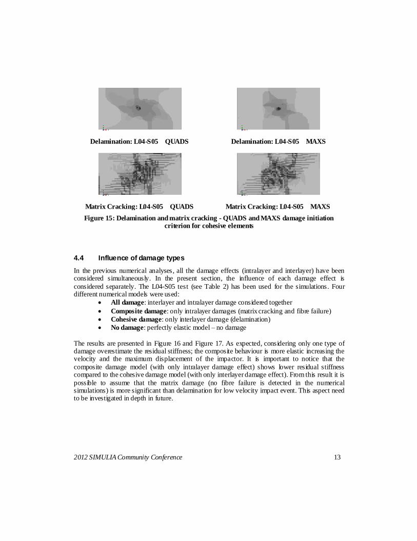
Delamination: L04-S05 QUADS
Delamination: L04-S05 MAXS
Matrix Cracking: L04-S05 QUADS
Matrix Cracking: L04-S05 MAXS
Figure 15: Delamination and matrix cracking - QUADS and MAXS damage initiation criterion for cohesive elements
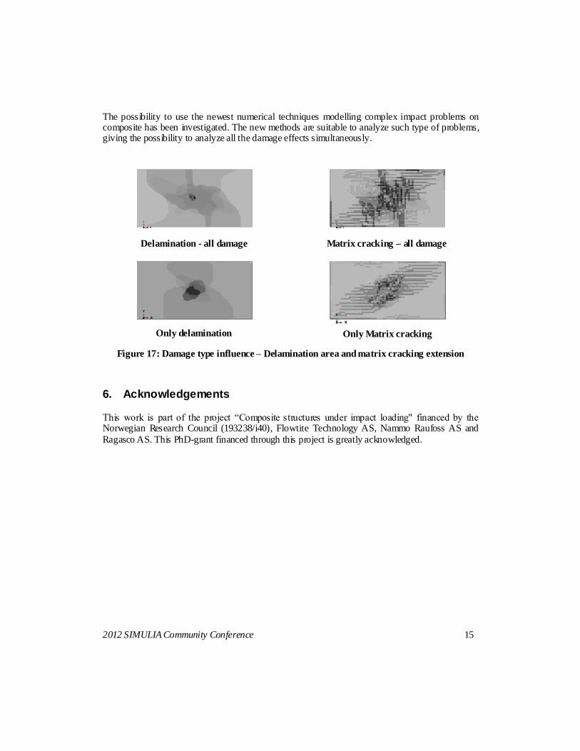
4.4 Influence of damage types
In the previous numerical analyses, all the damage effects (intralayer and interlayer) have been considered simultaneously. In the present section, the influence of each damage effect is
considered separately. The L04-S05 test (see Table 2) has been used for the simulations. Four different numerical models were used:
All damage: interlayer and intralayer damage considered together
Composite damage: only intralayer damages (matrix cracking and fibre failure)
Cohesive damage: only interlayer damage (delamination)
No damage: perfectly elastic model – no damage
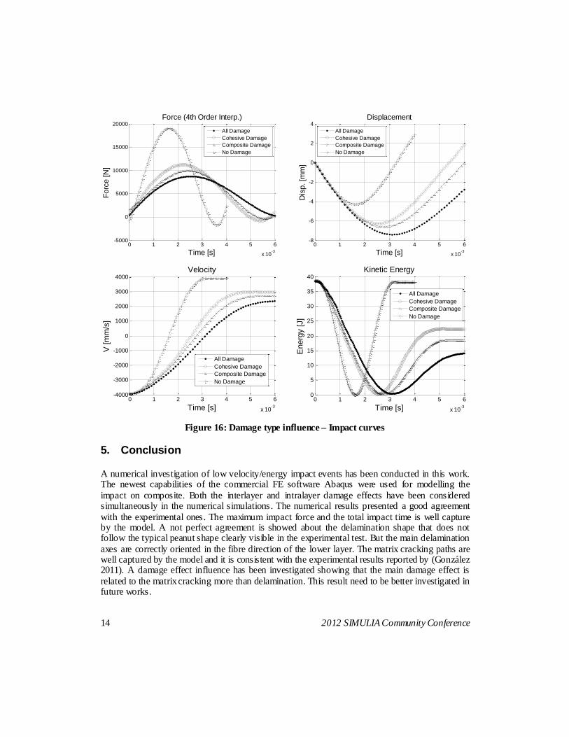
The results are presented in Figure 16 and Figure 17. As expected, considering only one type of damage overestimate the residual stiffness; the composite behaviour is more elastic increasing the velocity and the maximum displacement of the impactor. It is important to notice that the
composite damage model (with only intralayer damage effect) shows lower residual stiffness compared to the cohesive damage model (with only interlayer damage effect). From this result it is
possible to assume that the matrix damage (no fibre failure is detected in the numerical simulations) is more significant than delamination for low velocity impact event. This aspect need to be investigated in depth in future.
14 2012 SIMULIA Community Conference
Figure 16: Damage type influence – Impact curves
5. Conclusion
A numerical investigation of low velocity/energy impact events has been conducted in this work. The newest capabilities of the commercial FE software Abaqus were used for modelling the
impact on composite. Both the interlayer and intralayer damage effects have been considered simultaneously in the numerical simulations. The numerical results presented a good agreement
with the experimental ones. The maximum impact force and the total impact time is well capture by the model. A not perfect agreement is showed about the delamination shape that does not follow the typical peanut shape clearly visible in the experimental test. But the main delamination
axes are correctly oriented in the fibre direction of the lower layer. The matrix cracking paths are well captured by the model and it is consistent with the experimental results reported by (González 2011). A damage effect influence has been investigated showing that the main damage effect is
related to the matrix cracking more than delamination. This result need to be better investigated in future works.
0 1 2 3 4 5 6
x 10-3
-5000
0
5000
10000
15000
20000
Time [s]
Forc
e [N
]
Force (4th Order Interp.)
All Damage
Cohesive Damage
Composite Damage
No Damage
0 1 2 3 4 5 6
x 10-3
-8
-6
-4
-2
0
2
4
Time [s]
Dis
p. [m
m]
Displacement
All Damage
Cohesive Damage
Composite Damage
No Damage
0 1 2 3 4 5 6
x 10-3
-4000
-3000
-2000
-1000
0
1000
2000
3000
4000
Time [s]
V [m
m/s
]
Velocity
All Damage
Cohesive Damage
Composite Damage
No Damage
0 1 2 3 4 5 6
x 10-3
0
5
10
15
20
25
30
35
40
Time [s]
Energ
y [J]
Kinetic Energy
All Damage
Cohesive Damage
Composite Damage
No Damage
2012 SIMULIA Community Conference 15
The possibility to use the newest numerical techniques modelling complex impact problems on composite has been investigated. The new methods are suitable to analyze such type of problems, giving the possibility to analyze all the damage effects simultaneously.
Delamination - all damage
Matrix cracking – all damage
Only delamination
Only Matrix cracking
Figure 17: Damage type influence – Delamination area and matrix cracking extension
6. Acknowledgements
This work is part of the project “Composite structures under impact loading" financed by the Norwegian Research Council (193238/i40), Flowtite Technology AS, Nammo Raufoss AS and
Ragasco AS. This PhD-grant financed through this project is greatly acknowledged.
16 2012 SIMULIA Community Conference
7. Reference
1. "Abaqus Analysis User's Manual."
2. "Abaqus Theory Manual."
3. "ASTM D7136 / D7136M - 07 Standard Test Method for Measuring the Damage Resistance of a Fiber-Reinforced Polymer Matrix Composite to a Drop-Weight Impact Event."
4. Abrate, S. (1998). "Impact on composite structures." Cambridge University Press: 289.
5. Abrate, S. (2001). "Modeling of impacts on composite structures." Compos Struct.
6. Barenblatt (1962). "The mathematical theory of equilibrium cracks in brittle fracture." advances in Applied Mechanics.
7. Davies, O. (2004). "Impact on composite structures." The aeronautical Journal.
8. Dugdale (1960). "Yielding of steel sheets containing slits." Journal of the Mechanics and Physics of Solids.
9. Gong SW, T. S., Shim VPW (1994). "The elastic response of orthotropic laminated cylindrical shells to low-velocity impact." Compos Engineering
10. Gong SW, T. S., Shim VPW (1995). "Impact response of laminated shells with orthogonal curvatures." Compos Engineering.
11. González (2011). "Simulation of interlaminar and intralaminar damage in polymer-based composites for aeronautical applications under impact loading." Thesis.
12. Hashin (1980). "Failure criteria for unidirectional composites." J Appl Mech 47: 329-334.
13. Hillerborg (1976). "Analysis of crack formulation and crack growth in concrete by means of fracture mechanics and finite elements." Cement and Concrete Research.
14. Naik NK, C. Y. (2000). "Damage in woven-fabric composites subjected to lowvelocity impact." Compos Sci Technol.
15. Olsson, D. M., Falzon BG (2006). "Delamination threshold load for dynamic impact on plates." Int J Solids Struct.
16. Olsson, R. (2001). "Analytical prediction of large mass impact damage in composite laminates." Appl Sci Manuf.
17. Puck, A., J. Kopp, et al. (2001). "Guidelines for the determination of the parameters in Puck's action plane strength criterion." Composites Science and Technology 62(3): 371-378.
18. Puck, A. and H. Schürmann (1998). "Failure analysis of FRP laminates by means of physically based phenomenological models." Composites Science and Technology 58(7): 1045-1067.
19. Puck, A. and H. Schürmann (2001). "Failure analysis of FRP laminates by means of physically based phenomenological models." Composites Science and Technology 62(12-13): 1633-1662.
20. Zhou, G. (1998). "The use of experimentally-determined impact force as a damage measure in impact damage resistance and tolerance of composite structures." Compos Struct