Embed Size (px)
Citation preview

THE JOURNAL OF THE
ROYAL SIGNALS AMATEUR RADIO SOCIETY
NUMBER 18 JANUARY 1967
OFFICERS OF THE SOCIETY PRESIDENT: Brigadier D.R. HORSFIELD, OBE, MA, AMIEE,
Director of Telecommunications
VICE PRESIDENT: Major General E.S. COLE, (Retd), CB, CBE. CALL SIGN G2EC
TREASURER: Captain J.A. TONNISON, Royal Signals,
24th Signal Regiment,
Catterick Camp,
Yorkshire.
HQ SECRETARY: Lieutenant Colonel (Retd) J.S. MARTINSON
Signals 1(A),
Defence Signal Staff,
Ministry of Defence,
LONDON, S.W.1.
FIELD SECRETARY: Major L.S. BEAUMONT, CALL SIGN G3RUS
24th Signal Regiment,
Catterick Camp,
Yorkshire.
HEADQUARTERS STATION - CATTERICK CAMP - GB3RCS/G3CIO/G4RS
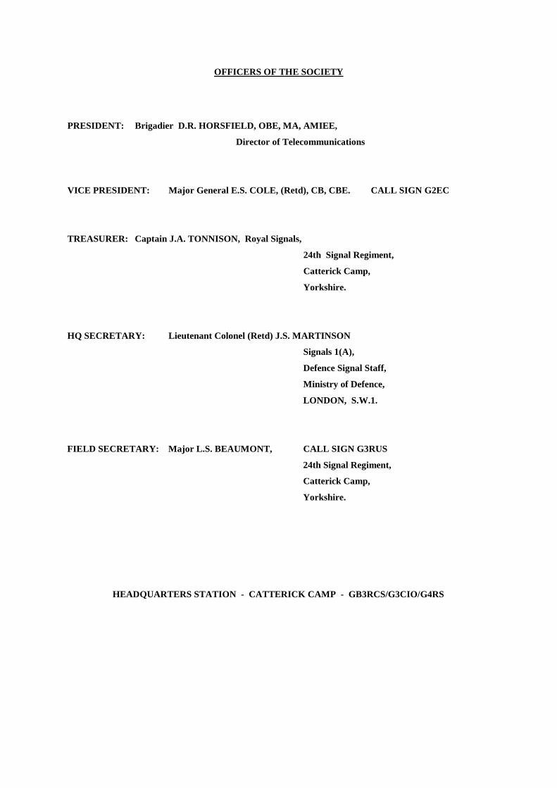
CONTENTS
Editorial ...................................................................................................... 1
Activity Periods .......................................................................................... 1
Some Thoughts on AM (by G3EJF) ........................................................... 2
The RSGB Exhibition - One Man’s View .................................................. 6
Lets Have a Look at It (by G5YN) ............................................................. 8
Awards Roll Call ........................................................................................ 13
From the Mail Bag ...................................................................................... 15
Clangers ...................................................................................................... 15
Stop Press .................................................................................................... 15
Member and Club Activities ....................................................................... 16
QTH Amendments ...................................................................................... 17
Silent Key ................................................................................................... 17
Minutes of the Annual General Meeting..................................................... 18
Rules for the Royal Signals Amateur Award .............................................. 26
Nota Bene - G4RS ...................................................................................... 27
Available from Headquarters .......................................................... Back cover
E D I T O R I A L CALLING CQ DOG X-RAY
Elsewhere in this issue will be found the minutes of the AGM. Quite a notable one at which some fifty members attended (I0% of our strength). Yes, the interest is there all right. A few points arising from the minutes of particular moment are worthy of repetition and the first one must surely be, for me to endorse, on behalf of all members, the vote of thanks attended to G3EJF. He has (in this man's humble opinion) virtually carried the Society for three years plus. Sorry, no golden handshake, but thank you JOHNNY. The 'SOCIETY' stand at SEYMOUR HALL, so ably organised by TED PHILP (G3NJM) was a "magnificent job" (quote from SWM - praise indeed). His ROYAL HIGHNESS, PRINCE PHILIP, opened the Exhibition from our stage and from that moment onwards it was a question of all hands on deck and every man for himself. There can be few of the 10,000 who came to SEYMOUR HALL who did not come to see our stand (in fact, on the Saturday it is believed that they were all on the stand at the same time !). During the verbal battle raised at the Meeting, 'to contest or not to contest'. (G5YN still trying to reform G5HZ!), a comment, "why don't you try the top band," stung G3C10 into action in November for the SWM MCC contest. your editor now inclines to the belief that after all there is something in it. Though not aspiring to any fame we managed about a hundred contacts and had a most enjoyable time. With great reluctance we have to announce an increase (from 2s. 6d. to 5s. 0d.) in annual subscriptions, payable wef 1 Jan 67. This has been brought about solely by the increase in Postal Rates. For the same reason the price of Society QSL cards has risen slightly - but they are still ridiculously cheap. We look forward to hearing from you in 1967. A SAE is always welcome where a direct reply is required. Please include your Membership Number on correspondence - it helps. Technical articles (Not TOO technical) are most urgently required. Your help is requested. Lastly, on behalf of the officers of the Society and the Staff of G3CIO - A VERY HAPPY AND PROSPEROUS NEW YEAR to you all. Good Hunting es 73 G3RUS ----------------------------------------------------------------------------------------------------------------------------
ACTIVITY PERIODS On the LAST SUNDAY OF EACH MONTH from 1000-1200 and 1400-1600 UK time. Approx. frequencies:- 3530, 14050 and 21050 Kc/s on CW 3700, 14120 and 21150 Kc/s on Phone (SSB or AM) UK members are particularly asked to attempt to contact overseas members on 14 and 21 Mc/s during these periods. Ring these dates on your calendar:- Jan 29 Feb. 26 Mar 26 Apr. 30
BCNU
1
SOME THOUGHTS ON A.M. BY G3EJF
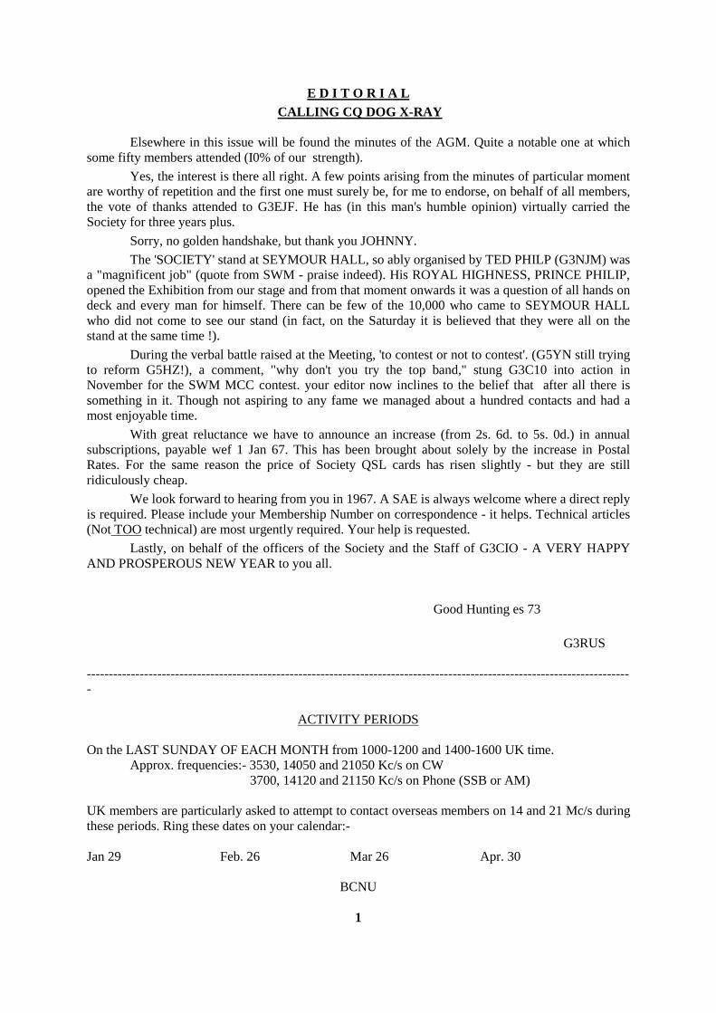
In this year of grace it would not be unfair to say that all the DX is being worked on CW or SSB and that by far the majority of AM contacts are confined to relatively local QSO’s particularly on the lower frequencies. The exceptions are of course the VHF bands where the majority of stations still use A.M. Leaving aside these exotic frequencies and concentrating our attention on bands such as 80 Metres it appears likely that many people will still build or rebuild A.M. transmitters. It is to these hardy souls that these thoughts are directed. Let us consider the average AM transmitter; having built an RF section capable of giving something like 66% efficiency at the legal 150 watts input one is faced with the task of producing some 75 watts of audio and achieving correct matching between the P.A. and the modulator. Having built this clumsy beast and bought a table strong enough to stand its weight plus that of its power supplies the owner often finds himself troubled by TVI, usually due to harmonic radiation. One of the fallacies that one often hears on the bands is that using SSB will cure TVI. Using SSB will cure nothing, using linear amplifiers will and it just happens that one has to use linear amplifiers on SSB because the signal is already modulated when it is fed to the final. Could we not then use this technique with AM ? Ah yes but what about efficiency says the man who always finds a snag in any suggestion. Granted that if your amplifier is linear the efficiency will be less than in class C but read on mate and you will find that the author isn't just touting for business for the Electricity Board (Confirmed ED). Briefly what is being suggested is that we should modulate at low level and follow the modulated stage by one or more linear amplifiers with the consequent suppression of those harmonics which cause so much trouble. This is already done in a considerable number of commercial high power transmitters so it's not exactly new. The problem of A.M. stations with enormous bandwidths splattering all over the place has always been with us but we tend to forget that there are causes other than overmodulation. Very often the high power modulator stage is anything but linear and the match between the modulator and the PA may leave a lot to be desired. Either of these faults may result in intermodulation products; these frequencies are produced when two or more audio frequencies in a non-linear stage combine to produce new and often higher frequencies. The result is that the sidebands contain frequencies far higher than those present in the voice of the operator. Right then, let's get rid of high power modulator stages and modulation transformers altogether. For the last twelve years the writer has been using a transmitter for all bands from 80 to 10 metres with an 807 in the final running at 50 watts on CW. On AM the final is Clamp Valve Modulated with the PA anode current meter indicating an input of about 40watts on speech peaks. Reports have always been good but the final encouragement to rush into print came when a station said he preferred the quality of the signal from ‘EJF to that from the LG300 at 'CIO. This was over a month ago and he hasn’t tried to borrow anything yet so perhaps he meant it. The use of a clamp valve in a CW transmitter has been for many years a convenient way of holding the PA anode current within limits whilst keying some previous stage. The basic circuit; is shown in Fig 1.
2
3
4
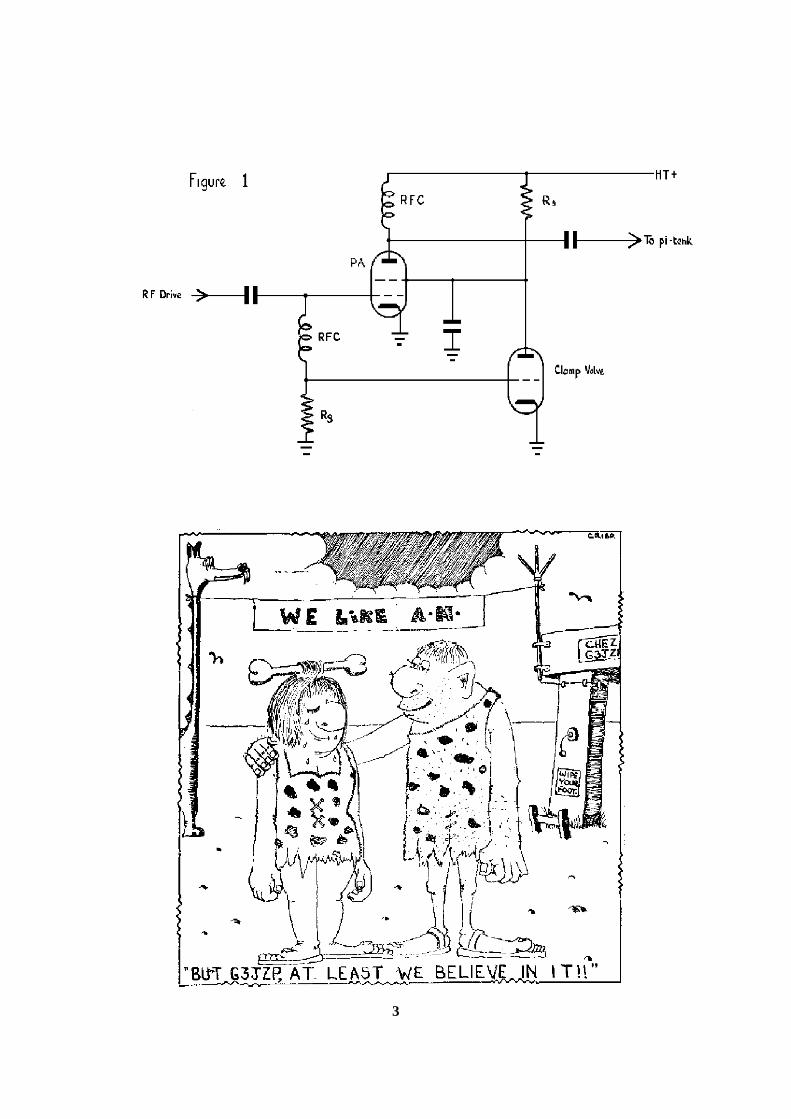
With the key up there is no RF drive and hence no bias on the clamp valve which therefore draws a high anode current through Rs. There is a large voltage drop across Rs and hence the screen on the PA is low and the PA anode current is much reduced. When the key is pressed and drive applied the clamp valve receives a high negative bias and draws very little anode current. The voltage drop across Rs is therefore quite small and the PA anode current rises to its normal operating value as the screen voltage of the PA is now at its normal value. If the bias to the clamp valve were derived from the output of an A.F. amplifier it would be possible to modulate the P.A. by this means. Figure 2 shows the circuit used by the writer. It will be seen that variable control of the PA input is provided by means of the 50K potentiometer in the PA grid circuit. The parasitic stopper in the PA grid circuit L1 & R1 consists of 8 turns of 22 swg enamelled wire wound on a 200 ohm 1 watt resistor. The valves used for the speech amplifier are EF50's. Twelve years ago these were cheap and plentiful, they still are, but on their own would give far too much amplification. To reduce the gain and to save buying a couple of electrolytics it was decided to put negative feedback on both stages by omitting the cathode by-pass capacitors. Assuming that the normal precautions are taken to prevent instability such as careful screening of the audio stages there appears to be only one secret of success. Before using phone the transmitter must be loaded up to its full CW operating input, throw the CW/Phone switch and off you go. Failure to fully load the PA on CW first will result in the woolly sounding speech that one sometimes hears from efficiency modulated transmitters, The unmodulated input with the switch at Phone is of the order of 15 to 20 watts. If this transmitter doesn't make a big enough hole in the ether for your taste then add a linear amplifier. Whilst the writer has never seen a ruling on this he would imagine that provided the reduced unmodulated carrier did not exceed 150 watts input to the final linear amplifier and that speech peaks did not exceed the maximum permitted p.e.p. for SSB then licence regulations would be complied with. Now how does all this work out from the power supply angle. The speech amplifier only consumes a few milliamps and can conveniently be powered by the same power pack as the driver stages. Whilst a linear amplifier would consume more power than a 150 watt class C stage there are no modulator power supplies to consider so we're about quits. The great advantage is that we have deloused the transmitter, no harmonics, no intermodulation products and think what a fine doorstop that old modulation transformer will make.
5
THE RSGB EXHIBITION - ONE MAN’S VIEW The average reader of MERCURY will already have seen in the Amateur Radio journals detailed accounts of the various exhibits at the 1966 International Radio Communications Exhibition. The writer does not intend to duplicate these accounts but looks back on the event long after the aching feet and sore larynx have returned to normal. Of course one’s memories are a jumble of disconnected incidents which it is difficult to arrange into a pattern but the effort must be made. Have you ever entered an exhibition hall the evening before the opening? The scene is one of apparently utter chaos, carpenters planing off rough corners and painters applying a final coat here and there. Despite the chaos there is no sign of panic, only those of little faith doubt whether it will all be ready on time. During the exhibition life is one embarrassment after another as people whose faces are familiar greet you, I even failed to recognise the Editor of The Wire! Apart from looking, perhaps enviously, at the equipment on display it is very much a social occasion as "eyeball QSO’s" take place in the bar and restaurant. I found it impossible to go for a cuppa without someone I knew joining me for a natter. One aspect which has changed over the years since the first exhibition was held after the war is the increasing number of overseas visitors, you could make WAC if not DXCC in the bar. Now the writer has neither the cash nor the inclination to invest in the exotic equipment on display. However I have no bias against commercial gear so the following opinions are not coloured by prejudice. Two things struck most forcibly, the enormous range of books and booklets on various aspects of Amateur Radio which are available today and the very high standard of construction of many of the transistorised transmitters and receivers on show, a standard far higher than many of the valve jobs I thought. To the home constructor the large range of components and modules made available by the STC - Electroniques tie up must have been of great interest while the stands selling “surplus” items were a useful source of cheap bits. Any gear the writer builds in the next year or so will have stacks of 0·01 microfarad decoupling capacitors in it, I got 200 for 25s. 0d. Spoilt by use of modern service-type equipment it was amazing to see the results people were getting on RTTY using clapped-out Creed 7B’s etc. As usual the RSGB stand included two working stations but why must they stick to 80m all the time, surely with the increased international co-operation which is a feature of Amateur Radio in this day and age it would be a good thing to stress the international aspect by spending at least half the time on the DX bands. It was good to see at least two displays of cases for equipment, this is perhaps the most difficult part of building an elegant looking rig. Probably the most lasting impression one gets is the compactness of most of the commercial gear, mini-cars, mini-skirts and now mini-rigs, the ultimate being an all-band receiver measuring 6” x 7” x 4”. On the Royal signals stand the crystal calibration service proved most popular, more than one visitor arrived with a paper bag containing some fifty or more crystals and left them while he looked round the exhibition. Using the callsign GB3RCS the club station at Bampton was operated over landlines from the stand and many interesting QSO’s were made including the RSGB’s exhibition station GB3RS. This QSO may well have created a record as QSL cards were exchanged before the end of the contact. We’ve all heard of long QSO’s that with W7ARS in Tucson, Arizona, measured over nine feet!
6

This was the first time that the Regular Army had been represented and the presence of the Corps was apparent to all as off-duty members in uniform took the opportunity to look round the stands or take it easy in the various refreshment rooms. From assistance to other exhibitors in getting ready for the opening to the provision of a clean handkerchief to blindfold G3SGN for the draw on the last evening those manning the Corps stand helped when they could, talked to thousands of visitors, posed for photographers and generally found it a shattering but worth while experience. It is to be hoped that the powers-that-be also found it worthwhile and that this was the first of many Royal Signals appearances at the Radio Amateurs' own show
7
"LETS HAVE A LOOK AT IT" by G5YN
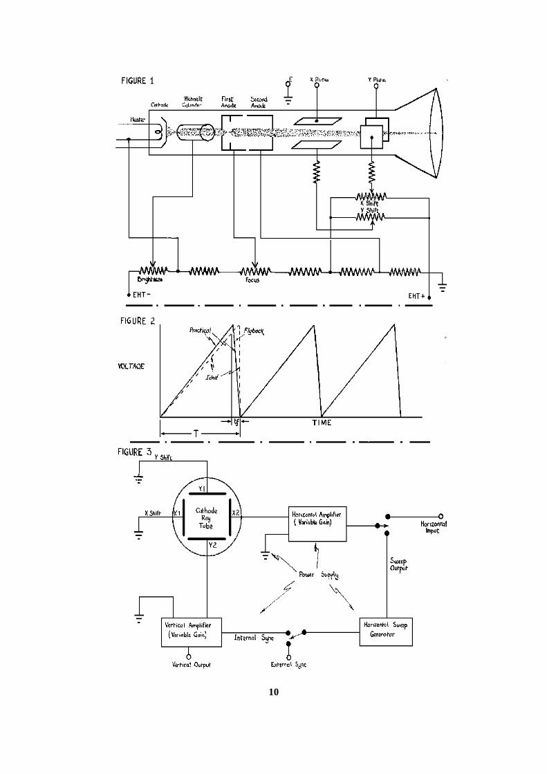
For many years pointer instruments of varying degrees of simplicity (or complexity) and accuracy were good enough to indicate the AC or DC voltages and currents in electrical equipment under construction, investigation or in use in the laboratory or ham shack. With the increasing complexity and sophistication of electronic equipment the information which such instruments can provide is frequently not enough. It is often necessary to be able to see the waveform of an alternating quantity. The instrument which enables you to do this is the "oscilloscope". This consists basically of a stream of electrons which are accelerated and focused onto a fluorescent screen. The point at which they strike appears as a bright spot. Means are provided of deflecting the beam so that the bright spot moves across the screen producing a bright line. Persistence of vision enables repetitive waveforms to be seen as stationary curves. Let us see how a simple cathode ray tube is constructed. First there is the source of electrons, a heater and cathode as in a valve. This is followed by a tube known as the Wehnelt cylinder. This is maintained at a small negative potential which is variable. It controls the flow of electrons as does the grid of a valve. As the brightness of the spot on the tube face depends on the number and velocity of electrons striking it the adjustment that controls the potential of the Wehnelt cylinder is in effect the brightness control. The Wehnelt cylinder is followed by two anodes. The second is maintained at a high positive potential and the first at a lower variable positive potential. The effect of the difference of potential between the two anodes is to form an electrostatic field which acts on the electron stream in the same way as does a convex lens on light and causes the electrons to converge onto one point. The potential of the first anode is adjusted until this spot lies on the phosphor covered face of the tube. This adjustment is therefore called the focus control. Following the two anodes are two pairs of parallel plates. By applying different potentials to them the stream of electrons can be deflected in the vertical and horizontal planes. Apart from the voltages under investigation adjustable voltages or bias are applied to the plates so that the position of rest of the spot can be adjusted to any desired point on the screen. The first pair of plates deflects the beam in the vertical plane and is called the "Y" plates. The second pair deflects the beam in the horizontal plane and is called the "X" plates. The two controls are known as the X and Y Shift Controls. The upper part of Fig 1 shows a diagram of a simple tube. The lower part of Figure 1 shows the chain of resistors and potentiometers connected across the EHT supply with the various controls. It must be noted that EHT +ve is earthed and that the cathode is at a high negative potential with respect to earth.
8

Before a tube can be used to display waveforms certain ancillary items are needed. If a recurrent waveform is applied to the Y plates and nothing to the X plates all that will appear is a vertical bright line on the screen. To expand this into a curve the spot must at the same time be drawn at a steady rate left to right across the screen and returned quickly to the left at the end of each stroke. This must be carried out at the correct speed so that the waveform will appear stationary. The part of the equipment which does this is called the time base. It is an oscillator which produces a waveform of the type shown in Figure 2, commonly called "sawtooth". Ideally the steadily rising voltage would occupy the whole period T and the return to zero or "flyback" would be instantaneous. This of course is impossible and the flyback will occupy a short time tf. Circuitry is included to extinguish the spot during this period. A sawtooth waveform is basically produced by charging a condenser from a constant current source so that the charge in the condenser and hence the voltage across it rises linearly. To produce the flyback the condenser is short circuited. The circuit techniques to approximate to these ideals fill books and will not be entered into in this short article. It is seldom that the amplitude of the waveform to be investigated or of the output of the sawtooth generator is sufficient to sweep the spot completely across the tube. This applies particularly to the waveform under investigation. It is therefore necessary to provide amplifiers between the vertical input terminal and the Y plates and between the sawtooth generator and the X plates. These amplifiers must have the necessary gain (variable), bandwidth and output and be linear. At Figure 3 is a block diagram of a simple 'scope. This indicates single ended amplifiers which are now only found in the simplest instruments. In 'scopes of any quality push pull amplifiers with their greater linearity and output are used. The shift controls then vary the relative d.c. potential of the two anodes which are directly connected to the X and Y plates. The remaining essential facility is that of being able to lock the frequency of the sawtooth generator to that of the signal under investigation so that constant critical adjustment of the former is not necessary to ensure that the trace on the screen remains steady. A portion of the output of the vertical amplifier is introduced into the sawtooth generator. This operation is known as synchronisation. Having discussed in simple terms what a 'scope is and how it works, let us see some of the things it can do to help the amateur: - 1. Checking the performance of audio amplifiers 2. Aligning receiver tuned circuits 3. Measuring and monitoring modulation depth 4. Setting up single sideband equipment 5. Measurement of alternating voltage, frequency and phase Let as start by checking an audio amplifier. The block diagram of the set up is shown at Figure 4A. The audio oscillator must be capable of supplying either a very pure sine wave or a square wave over the range of frequencies that the amplifier must cover. First a sine wave is injected into the amplifier. If the picture on the ‘scope is also a sine wave then you know that your amplifier is free of harmonic distortion. If one peak is flattened as at B then there is 2nd harmonic present. Third harmonic, which makes particularly nasty noise, gives a picture like C. Flattening of both peaks as at D indicates over-loading.
9
10
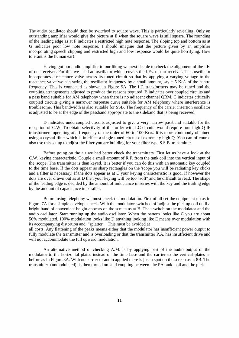
The audio oscillator should then be switched to square wave. This is particularly revealing. Only an outstanding amplifier would give the picture at E when the square wave is still square. The rounding of the leading edge as at F indicates a restricted high note response. The sloping top and bottom as at G indicates poor low note response. I should imagine that the picture given by an amplifier incorporating speech clipping and restricted high and low response would be quite horrifying. How tolerant is the human ear! Having got our audio amplifier to our liking we next decide to check the alignment of the I.F. of our receiver. For this we need an oscillator which covers the I.Fs. of our receiver. This oscillator incorporates a reactance valve across its tuned circuit so that by applying a varying voltage to the reactance valve we can swing the oscillator frequency by a small amount, say ± 5 Kc/s of the centre frequency. This is connected as shown in Figure 5A. The I.F. transformers may be tuned and the coupling arrangements adjusted to produce the reasons required. B indicates over coupled circuits and a pass band suitable for AM telephony when there is no adjacent channel QRM. C indicates critically coupled circuits giving a narrower response curve suitable for AM telephony where interference is troublesome. This bandwidth is also suitable for SSB. The frequency of the carrier insertion oscillator is adjusted to be at the edge of the passband appropriate to the sideband that is being received. D indicates undercoupled circuits adjusted to give a very narrow passband suitable for the reception of C.W. To obtain selectivity of this order with LC circuits would require four high Q IF transformers operating at a frequency of the order of 60 to 100 Kc/s. It is more commonly obtained using a crystal filter which is in effect a single tuned circuit of extremely high Q. You can of course also use this set up to adjust the filter you are building for your filter type S.S.B. transmitter. Before going on the air we had better check the transmitters. First let us have a look at the C.W. keying characteristic. Couple a small amount of R.F. from the tank coil into the vertical input of the 'scope. The transmitter is than keyed. It is better if you can do this with an automatic key coupled to the time base. If the dots appear as sharp rectangles on the 'scope you will be radiating key clicks and a filter is necessary. If the dots appear as at C your keying characteristic is good. If however the dots are over drawn out as at D then your keying will be too "soft" and be difficult to read. The shape of the leading edge is decided by the amount of inductance in series with the key and the trailing edge by the amount of capacitance in parallel. Before using telephony we must check the modulation. First of all set the equipment up as in Figure 7A for a simple envelope check. With the modulator switched off adjust the pick up coil until a bright band of convenient height appears on the screen as at B. Then switch on the modulator and the audio oscillator. Start running up the audio oscillator. When the pattern looks like C you are about 50% modulated. 100% modulation looks like D anything looking like E means over modulation with its accompanying distortion and "splatter". This must be avoided at all costs. Any flattening of the peaks means either that the modulator has insufficient power output to fully modulate the transmitter and is overloading or that the transmitter P.A. has insufficient drive and will not accommodate the full upward modulation. An alternative method of checking A.M. is by applying part of the audio output of the modulator to the horizontal plates instead of the time base and the carrier to the vertical plates as before as in Figure 8A. With no carrier or audio applied there is just a spot on the screen as at 8B. The transmitter (unmodulated) is then turned on and coupling between the PA tank coil and the pick
11
12
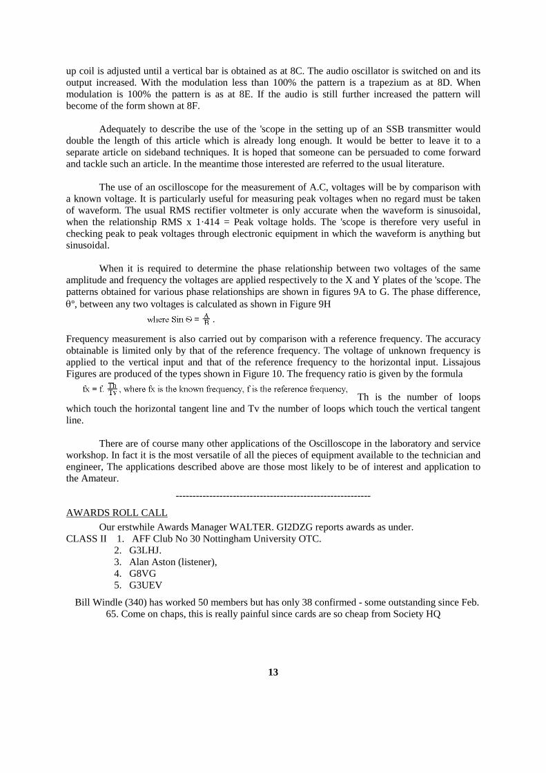
up coil is adjusted until a vertical bar is obtained as at 8C. The audio oscillator is switched on and its output increased. With the modulation less than 100% the pattern is a trapezium as at 8D. When modulation is 100% the pattern is as at 8E. If the audio is still further increased the pattern will become of the form shown at 8F. Adequately to describe the use of the 'scope in the setting up of an SSB transmitter would double the length of this article which is already long enough. It would be better to leave it to a separate article on sideband techniques. It is hoped that someone can be persuaded to come forward and tackle such an article. In the meantime those interested are referred to the usual literature. The use of an oscilloscope for the measurement of A.C, voltages will be by comparison with a known voltage. It is particularly useful for measuring peak voltages when no regard must be taken of waveform. The usual RMS rectifier voltmeter is only accurate when the waveform is sinusoidal, when the relationship RMS x 1·414 = Peak voltage holds. The 'scope is therefore very useful in checking peak to peak voltages through electronic equipment in which the waveform is anything but sinusoidal. When it is required to determine the phase relationship between two voltages of the same amplitude and frequency the voltages are applied respectively to the X and Y plates of the 'scope. The patterns obtained for various phase relationships are shown in figures 9A to G. The phase difference, θº, between any two voltages is calculated as shown in Figure 9H Frequency measurement is also carried out by comparison with a reference frequency. The accuracy obtainable is limited only by that of the reference frequency. The voltage of unknown frequency is applied to the vertical input and that of the reference frequency to the horizontal input. Lissajous Figures are produced of the types shown in Figure 10. The frequency ratio is given by the formula
Th is the number of loops
which touch the horizontal tangent line and Tv the number of loops which touch the vertical tangent line. There are of course many other applications of the Oscilloscope in the laboratory and service workshop. In fact it is the most versatile of all the pieces of equipment available to the technician and engineer, The applications described above are those most likely to be of interest and application to the Amateur.
----------------------------------------------------------
AWARDS ROLL CALL Our erstwhile Awards Manager WALTER. GI2DZG reports awards as under. CLASS II 1. AFF Club No 30 Nottingham University OTC. 2. G3LHJ. 3. Alan Aston (listener), 4. G8VG 5. G3UEV
Bill Windle (340) has worked 50 members but has only 38 confirmed - some outstanding since Feb. 65. Come on chaps, this is really painful since cards are so cheap from Society HQ
13
14
15
16

LA2J is the Signals HQ Club Stn Royal Norwegian Signals also have their own CATTERICK BARRACKS (who said serves 'em right). VS9ALV ( - ) Sgt Lawbuary if you want another exotic on Top band!!
G3EKL (46) Ray Webb knows a good bargain. In happy anticipation he has estb the Rig and bought 1000 Society QSL cards!!
--------------------------------------------
QTH AMENDMENTS DES BARRY (VE3CLV) now at 67 HARCOURT RD, BUSHEY, HERTS and using his G call G3ONU. E. FORD (419) now with 237 Sig Sqn Singapore. J. WORTH (420) at same QTH. J.R. TERRY (407) now with 25 FD SQN RE BAOR. LES KINCH (405) with 7th Sig Regt BAOR. GEORGE BEASLEY (483) G3LNS at 219 MOSELEY RD, BIRMINGHAM 12. RON COX (442) G3V1S at 8 FIR TREE AVENUE, HEATHERSHAW, OLDHAM, LANCS. DENNIS BOWDEN (85) 9M2NF (G3PNF) with 1st Regt MALAYSIAN SIGNALS, KUALA LUMPUR. RAY WEBB (46) G3EKL with 30th Sig Regt BLANDFORD. JOHN AKEHURST (82) G3OAZ at 19 Meadowland Avenue, Hampden Park, Eastbourne, Sussex. GEORGE EDWARDS (480) G2UX at Chapel Street, Barford, Norwich, Norfolk. FRANK PENFOLD G3SDD 12 Fieldway Crescent, Northwood, Cowes. JOHN SWINNERTON G2YS 29 Beacon Way, Rickmansworth, Harts. SILENT KEY It is with deep regret that we learn of the sudden death on Sept. 15th of HAROLD HINTON (216) G3LWQ of Southport. A telegraphist of the Royal Engineers Signal Service during World War I, his fist kept that professional touch until the end. Using simple equipment HAROLD was a keen supporter of RSARS CW contests and his signal was always a pleasure to work. Our sympathy goes to his widow.
17
18
ACTION
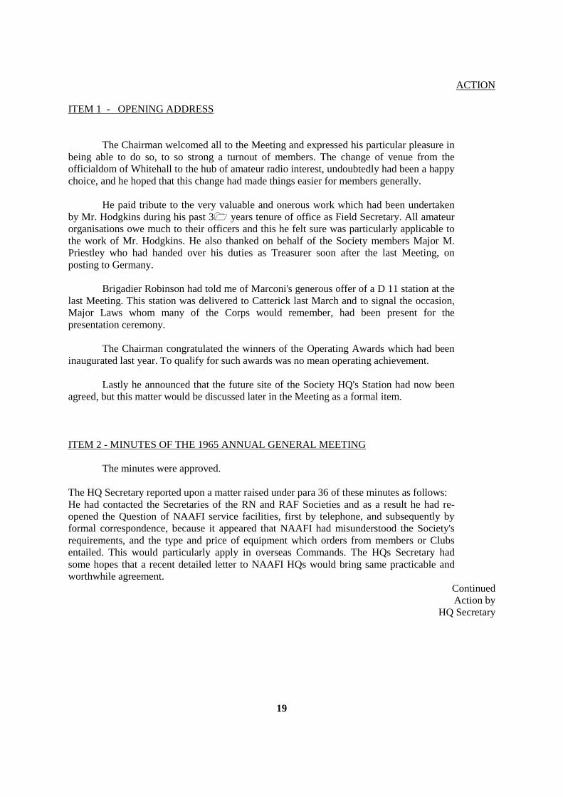
ITEM 1 - OPENING ADDRESS The Chairman welcomed all to the Meeting and expressed his particular pleasure in being able to do so, to so strong a turnout of members. The change of venue from the officialdom of Whitehall to the hub of amateur radio interest, undoubtedly had been a happy choice, and he hoped that this change had made things easier for members generally. He paid tribute to the very valuable and onerous work which had been undertaken by Mr. Hodgkins during his past 3 years tenure of office as Field Secretary. All amateur organisations owe much to their officers and this he felt sure was particularly applicable to the work of Mr. Hodgkins. He also thanked on behalf of the Society members Major M. Priestley who had handed over his duties as Treasurer soon after the last Meeting, on posting to Germany. Brigadier Robinson had told me of Marconi's generous offer of a D 11 station at the last Meeting. This station was delivered to Catterick last March and to signal the occasion, Major Laws whom many of the Corps would remember, had been present for the presentation ceremony. The Chairman congratulated the winners of the Operating Awards which had been inaugurated last year. To qualify for such awards was no mean operating achievement. Lastly he announced that the future site of the Society HQ's Station had now been agreed, but this matter would be discussed later in the Meeting as a formal item. ITEM 2 - MINUTES OF THE 1965 ANNUAL GENERAL MEETING The minutes were approved. The HQ Secretary reported upon a matter raised under para 36 of these minutes as follows: He had contacted the Secretaries of the RN and RAF Societies and as a result he had re-opened the Question of NAAFI service facilities, first by telephone, and subsequently by formal correspondence, because it appeared that NAAFI had misunderstood the Society's requirements, and the type and price of equipment which orders from members or Clubs entailed. This would particularly apply in overseas Commands. The HQs Secretary had some hopes that a recent detailed letter to NAAFI HQs would bring same practicable and worthwhile agreement.
Continued Action by
HQ Secretary
19
ACTION ITEM 3 - THE FUTURE SITE OF THE HEADQUARTERS STATION The Chairman expressed generally the reason why a move from our present site was brought about, These are very briefly summarised as :-
a. The move to Blandford in April next of the School of Signals, the subsequent necessary re-siting programme in Catterick and this effect upon the present HQ Station location.
b. Blandford would in many ways become the home of the corps, with a large
concentration of its members, and considerable floating population at all times.
c. The best technical backing of Corps tradesmen would be in the Blandford area. d. Liaison with the MOD would be easier, and a closer proximity to London would
greatly facilitate such occasions as, for example, the Corps Recruiting Display held this year in Golden Cross House, and indeed the Corps' very active participation in the Radio Society of Great Britain Exhibition. which we are now witnessing. This latter could also well prove to have attracted potential entrants to the Corps, in addition to the appeal to amateur radio enthusiasts.
The Chairman explained that he had been in close touch with the Commandant School of Signals upon the practicability of moving the HQs Station to Blandford next year as well as with the Commanders of Signal Units in Blandford. Accommodation in this area had been long earmarked, but there would now appear to be, subject to formal confirmation, an adequate site in the present AER non-permanent buildings which could be made available for at least a few years. This offer was made known by Major Philp. During discussion following this announcement the following points arose: a. Mr. Hodgkins, who admitted that up to last Annual General Meeting he was in Favour
of the Catterick site, said he now fully supported the move, but asked that Catterick be provided with some equipment, for example TX/RX etc. to be the basis of a Catterick Club, to provide facilities for Annual Reunion transmissions and to enable the training of keen young "would be hams" to continue. This was fully agreed.
b. The call sign to be used by the Blandford Station has raised many suggestions and it
was decided to approach the GPO discreetly through suitable liaison channels to enquire if an appropriate 'out out of sequence, call sign could be allotted. There was considerable feeling that the call sign G3CIO had meant Catterick for so long that it should remain there.
Field Secretary
20

ACTION c. Colonel Crump expressed Catterick’s anxiety that the details of the new Catterick
amateur Station site should be decided without delay, for pressing Catterick reorganisation reasons. The President gave assurance that this matter would be resolved through the Commander Training Brigade to whom he would be writing.
President d. Arising from the question of HQ' day to day maintenance, Colonel Crump stated he
would arrange for the present HQ Station NCO (Cpl Thompson) to be made available to move to Blandford. He pointed out that this would probably require School of Signals establishment action to regularise the arrangement
HQ Secretary
e. Upon the move to Blandford the question of the method of apportionment of Station equipment was queried. Much of this was taken over from the old Catterick Amateur Radio Club and there was a case for the retention of equipment at Catterick. On the other hand there was no justification, it was agreed, that Catterick should be unduly affluent, because there was scant interest outside the Camp. It was decided that A Working Party should convene at Catterick to decide upon the allocation of assets and to ensure that Catterick would retain adequate equipment to run a simple Station when the present HQ Station moves to Blandford.
Field Secretary
ITEM 4 - FIELD SECRETARY'S REPORT Following a year in which there were no changes among the officers of the Society, the past year has seen quite a number of changes and, if he could anticipate a later item on the agenda, there are more to come. He had always felt that one of the most important aspects of the Field Secretary’s duties was the publication of an issue of MERCURY each quarter. With a membership scattered throughout the world our journal was the only way we could keep in regular touch. The decision to pay members for contributions to MERCURY had increased the number of articles offered to a small degree, but we still needed more. Last year members would recall that he made the point that if MERCURY was too technical this was because it was the technicians who submitted the articles. He thought that members had taken the point and we have been able to include a non-technical, general interest, article each quarter. He would like to stress that to keep MERCURY going we needed a constant supply of articles of all types and he urged more members to have a go. Following upon criticism of the design of our members' QSL cards he had asked for suggestions for an alternative design in MERCURY. None were received. What comment there was preferred the present design so a further stock has been ordered from our printers. Unfortunately the price would have to be increased.
21
ACTION He saw from his post book that when we first provided this service the postage on 500 cards was 2/3d., it was now 3/6d. Apart from this the Purchase Tax we had to pay had gone up. The Society received some useful publicity from the efforts of members who have operated from exotic places. The visit to Kamaran Island by a group of Middle East members was particularly successful, over 3,000 contacts being made in the ten days operation. Membership has increased slowly throughout the year but a reduction in the number of affiliated clubs was occurring in view of the re-organisation of the Reserve Army. The Fund Raising Draw which took place during the year was a success thanks to the efforts of members, but there were signs that we were saturating the market and he would strongly recommend that we leave a gap of a year or two before attempting this again. We could well benefit in the long run. The main event at your HQs Station was the presentation of the Marconi HS27/HR28 installation of which members would have read in the Wire and the amateur radio press. This station was operated continuously on the 14 Mc/s band during Old Comrades weekend and made contact with many overseas Royal Signals stations. Altogether a total of over 400 contacts were made by our four transmitters during Reunion weekend and many visitors were shown round the station. Using the Marconi equipment the HQ Station had been active on radio-teleprinter and in its first contest using this mode of transmission was the second highest scoring UK station. At that stage, he felt he must express the Society's gratitude to the Chairman's predecessor, Brigadier Robinson, who was instrumental in arranging this magnificent gift. He was sure all members would wish to join him in wishing him a long and happy retirement. With the introduction of the Royal Signals Amateur Radio Award it was agreed to run monthly Activity Periods instead of an annual contest. Whether these Activity Periods have been a success it was difficult to say, and it may well be that this meeting would have other ideas. There had been a number of protests from members against the contests ending. We still hadn't solved the problem of getting members together on the air. The Award had got off to a good start and to date 4 members had received the Class II award and it was known that several more were near to qualifying. The Class I award was proving more difficult but that was as it should be. Whilst speaking of the Award he would like to thank Walter Caughey who has acted as Awards Manager and he was pleased to say was willing to continue in the appointment. Mr. Caughey had offered to waive his postage expenses as a small gesture to the Society. He was conscious that the meeting had many important things to discuss and it would be wrong of him to say more. However this was the last of these annual reports that he would be making and he felt he must express his thanks to all the people at Catterick and elsewhere whose assistance had made the job possible.
22
ACTION Particularly he would like to thank those members whose regular letters had kept him in touch with amateur radio matters in the Army and he must also thank, those members who had never written - he would really have been snowed under if they had. ITEM 5 - TREASURER'S REPORT The Treasurer explained that the presentation D 11 was systematically devalued every six months by the sum of 1,000 pounds. The insurance cost, at lowest possible tender, was 30 pounds per annum and this expenditure was obligatory. During discussion following the presentation the following financial points arose:
a. The Treasurer explained the extra work involved in accounting for subscription receipts spread around the 12 months, and it was agreed that subscriptions should be paid as at January 1st each year.
b. It was agreed that the annual subscription of 2/6d. was now quite inadequate to cover
the day to day running expenses, and indeed postage alone, and it was unanimously decided that the subscription be raised to 5/- per annum with effect from 1 Jan 1967. The Chairman pointed out that there was no question of profit making on this. The danger of resignations affecting the Society's welfare was discounted. Life membership fee would remain at 2 Guineas and affiliation fees would remain unaltered.
Motion proposed by Mr. Corsham and seconded by
Captain Webb
c. The Field Secretary's statement was agreed in that it would be financially unwise to hold a Lottery this year. Interest had fallen away on the second venture, and it was thought better to lie fallow for a year.
d. Mr. Hodgkins pointed out that Grants to clubs were a drain on resources, and the
purchase of the Racal receiver was mentioned. Perhaps also in any apportioning of HQ Station equipment on Blandford move, the old Catterick members should be borne in mind as some assets held from very early days were identified with Catterick, though there was now scant interest in amateur radio. After open discussion which followed on finance the following was decided:
(1) Recognition - The Society received no formal recognition as for the Corps Games
Clubs. Members felt very strongly that formal recognition should be afforded the Society. Would it be possible to change this situation.
HQ Secretary
23
ACTION (2) Major Douglas asked if his TA Club could apply for a Nuffield Grant in the same
way as the Regular Army. The HQ Secretary would look into this. HQ
Secretary (3) The President stated that the disbanding of the TA might render some equipment
available, which the Society could utilise. He suggested that anyone who had a specific case should put it up for consideration.
(4) Sgt Walker enquired which firms give discount. The Field Secretary assured him
that the list was published (or would be) in the MERCURY which admittedly goes to non-members, but all applications must in fact be endorsed by the Field Secretary personally, to vouch for their authenticity. Mr. Corsham asked if any guarantee was given and he was assured that it was.
ITEM 6 - ELECTION OF OFFICERS It was unanimously decided that Major Beaumont would assume the duties of Field Secretary forthwith from Mr. Hodgkins and that the present Treasurer and HQs Secretary should continue in office. ITEM 7 - DESIRABILITY OF HOLDING WINTER SEASON CONTESTS AND
ACTIVITY WEEKENDS AND TO RESTRICT THESE TO DISCRETE SECTIONS AND FREQUENCY BANDS TO BE USED
This item was tabled by Colonel Nepean, who felt that too many contests were carried out over all the frequency bands. (See his letter to MERCURY) and therefore was it not time to restrict the band usage and to advertise such intentions as a good example. During discussions which followed General Cole asked Mr. John Rouse if he would give his opinion. Mr. Rouse said he had no particular opinion, arguments for and against contests were a permanent feature of the hobby. Major Philp favoured the proposal but Major Beaumont was doubtful and Colonel Bower thought it was quite impracticable. In this Mr. Corsham agreed. He thought that undue interference might result to other users. Major Beaumont felt also that there were perhaps too many contests. It was asked if inter-Service contests were wanted, and Mr. Hodgkins replied that he had tested re-actions but without an echo. Eventually it was deemed advisable to drop the matter in view of no pronounced support for the motion.
24
ACTION ITEM 8 - ANY OTHER BUSINESS
a. Sunday morning activities - Sgt Ford suggested a regular Sunday morning net on the 3·5 Mc/s band. Field Secretary agreed to consider the suggestion.
b. Colonel Pargeter asked if there were any VHF transmitters active in Catterick. Mr.
Hodgkins replied that there were none from the HQ Station.
c. Colonel Bower stated that Royal Signals Records had from time to time difficulty in finding technicians for posting with amateur radio experience. They had little to refer to, and asked if they could be supplied with a list as comprehensive as possible.
d. WOI Caplan asked if we could get more publicity through periodicals etc. There was
the question of cost. Mr. Hodgkins said that it was normal practice to ensure that all likely Society contacts were sent leaflets. After the last Reunion 75 were sent leaflets but it was slow going. He said that back copies of MERCURY, as far as available, could and would be utilised where appropriate.
General Cole suggested that the minutes of the AGM should be sent to the Radio Society of Great Britain for inclusion in their bulletin. A copy will be sent.
Field Secretary
Major Philp suggested use of "Short Wave Magazine". Mr. Corsham thought that are should circularise the RE Signals ex members.
Field/HQ Secretary
It was felt by many members that an approach should be made by higher authority to Unit Commanders Royal Signals with a view to more Unit Amateur Radio Clubs being formed and affiliated to the Society. It was felt that this might best be achieved by good publicity and an approach to units on a 'non-official level'.
Field Secretary
WOI Caplan then offered to take on the duties of Society Publicity Officer. His offer was accepted nem con.
e. Invitation to visit Royal Signals Stand - Major Philp invited anyone who had not yet
done so to visit the Corps stand at the exhibition, sign the visitors' book and leave their QSL cards.
25
ACTION f. The RMAS Club Station - O/C Matthens explained that his station had been
functioning for some time, but with old end not very efficient equipment, He asked if on behalf of the RMA he could have assistance. The President, after ascertaining that no problem existed in providing suitable equipment from Command resources, asked Western Command Rep if he would arrange a Command visit to the RMAS to ensure the issue of the necessary items.
Western Command
g. WOI Caplan, seconded by S/Sgt Morris, moved that, on behalf of overseas members in particular, the Meeting should record a hearty vote of thanks to Mr. John Hodgkins in recognition of his long and most valuable term of office as Field Secretary.
This motion was carried unanimously.
The meeting was closed at 1810 hours.
RULES FOR THE ROYAL SIGNALS AMATEUR RADIO AWARD 1. The object of this award is to encourage activity amongst the transmitting and listener members of
Royal Signals Amateur Radio Society. 2. The award is available to all individual members of the Society and the affiliated clubs subject to
the conditions laid down in these rules. 3. The award will be made in two classes and will consist of a certificate for the Class II award and a
Royal Signals plaque for the Class I award . 4. Transmitting members must furnish proof of contact and Short Wave Listener members proof of
having heard, member stations as detailed below:- For the Class II award: 25 member stations including the Society's HQ station G3CIO/GB3RCS For the Class I award: 50 member stations including the Society's HQ station G3CIO/GB3RCS.
26
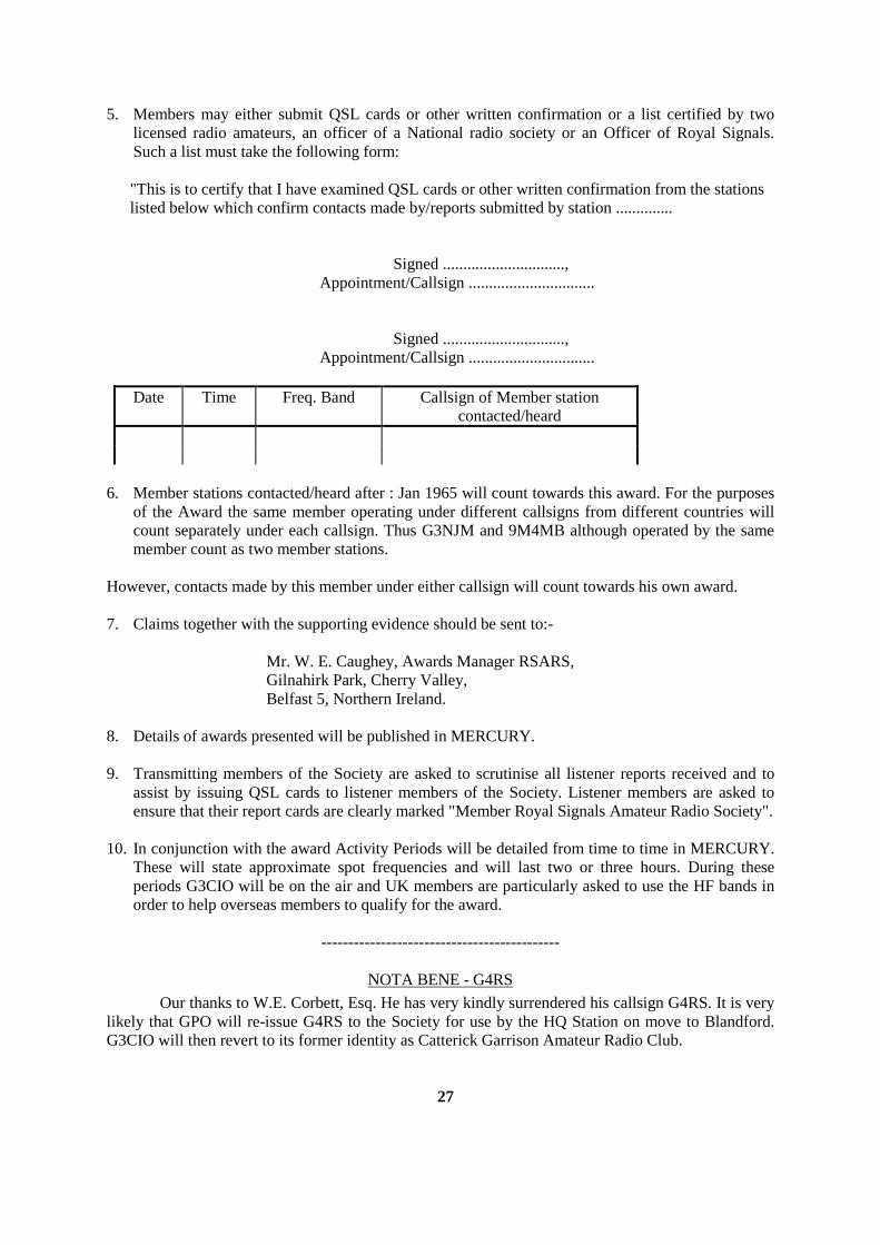
5. Members may either submit QSL cards or other written confirmation or a list certified by two licensed radio amateurs, an officer of a National radio society or an Officer of Royal Signals. Such a list must take the following form:
"This is to certify that I have examined QSL cards or other written confirmation from the stations listed below which confirm contacts made by/reports submitted by station ..............
Signed .............................., Appointment/Callsign ............................... Signed .............................., Appointment/Callsign ...............................
Date Time Freq. Band Callsign of Member station contacted/heard
6. Member stations contacted/heard after : Jan 1965 will count towards this award. For the purposes
of the Award the same member operating under different callsigns from different countries will count separately under each callsign. Thus G3NJM and 9M4MB although operated by the same member count as two member stations.
However, contacts made by this member under either callsign will count towards his own award. 7. Claims together with the supporting evidence should be sent to:- Mr. W. E. Caughey, Awards Manager RSARS, Gilnahirk Park, Cherry Valley, Belfast 5, Northern Ireland. 8. Details of awards presented will be published in MERCURY. 9. Transmitting members of the Society are asked to scrutinise all listener reports received and to
assist by issuing QSL cards to listener members of the Society. Listener members are asked to ensure that their report cards are clearly marked "Member Royal Signals Amateur Radio Society".
10. In conjunction with the award Activity Periods will be detailed from time to time in MERCURY.
These will state approximate spot frequencies and will last two or three hours. During these periods G3CIO will be on the air and UK members are particularly asked to use the HF bands in order to help overseas members to qualify for the award.
--------------------------------------------
NOTA BENE - G4RS
Our thanks to W.E. Corbett, Esq. He has very kindly surrendered his callsign G4RS. It is very likely that GPO will re-issue G4RS to the Society for use by the HQ Station on move to Blandford. G3CIO will then revert to its former identity as Catterick Garrison Amateur Radio Club.
27
AVAILABLE FROM HQ MEMBERS' NOTEPAPER This is a good quality white paper and costs 8/4d. per 100
sheets post free. MEMBERS' QSL CARDS The basic card cost 35/-. per 500 post free. We can overprint your
callsign, Name and address in black, red, blue or green for a further 15/- per 500, making a total price of 50/- per 500, less than a penny farthing each.
P.S. If you want to pass on information to HQ but can’t seem to catch G3CIO on the air you can still save the cost of a stamp. Look for G3LPC or G3LQC, our friends at Bampton, and pass the gen to them. They will store it on tape, the punched variety, and QSP it to Catterick on the next RTTY contact. -----------------------------------------------------------------------------------------------------------------------
ORDER FORM (Block letters please)
Name .................................................................................Callsign ............................................. Address ........................................................................................................................................ ..................................................................................................................................................... I enclose Cheque/Postal Order for ..................................................................Please supply :- .....................................sheets of Members Notepaper at 8/4d per 100 .....................................Basic QSL cards at 35/- per 500 .....................................QSL cards overprinted in ............................(state colour) at 50/- per 500
Cheques and Postal Orders to be crossed and made payable to Royal Signals Amateur Radio Society.