Embed Size (px)
Citation preview
07-98 en-938979/0
NUM 1000 FAMILY
CNC - NUM DRIVEMAINTENANCE
MANUAL0101938979/0

2 en-938979/0
Despite the care taken in the preparation of this document, NUM cannot guarantee the accuracy of the information it contains and cannot be held
responsible for any errors therein, nor for any damage which might result from the use or application of the document.
The physical, technical and functional characteristics of the hardware and software products and the services described in this document are subject
to modification and cannot under any circumstances be regarded as contractual.
The programming examples described in this manual are intended for guidance only. They must be specially adapted before they can be used in
programs with an industrial application, according to the automated system used and the safety levels required.
© Copyright NUM 1998.
All rights reserved. No part of this manual may be copied or reproduced in any form or by any means whatsoever, including photographic or magnetic
processes. The transcription on an electronic machine of all or part of the contents is forbidden.
© Copyright NUM 1998 software NUM 1000 family.
This software is the property of NUM. Each memorized copy of this software sold confers upon the purchaser a non-exclusive licence strictly limited
to the use of the said copy. No copy or other form of duplication of this product is authorized.
en-938979/0 3
Table of Contents
Table of Contents
Part 1: CNC1 General 1 - 1
1.1 Main Rack 1 - 31.2 Differences Between Versions 1 - 51.3 Panels 1 - 91.4 Additional Components 1 - 11
2 System Overview 2 - 1
3 Power Supplies 3 - 13.1 Rack Power Supply 3 - 33.2 Panel Power Supply 3 - 63.3 Keyboard Power Supply 3 - 7
4 Processors 4 - 14.1 CNC Processor 4 - 34.2 Machine (PLC) Processor 4 - 74.3 Graphic Processor 4 - 144.4 UCSII Monoprocessor 4 - 184.5 PCNC Processor 4 - 234.6 1020/1040 Motherboard 4 - 39
5 Memory 5 - 15.1 Memory Card 5 - 3
6 Axis card 6 - 16.1 Encoder Feedback Theory 6 - 36.2 Analogue Axis Card 6 - 46.3 QVN Axis Card 6 - 11
7 Input/Output Cards 7 - 17.1 I/O Card Display and Troubleshooting 7 - 37.2 32-Input Card 7 - 57.3 32-Output Card 7 - 77.4 32-Input/24-Output Card (with Sub.D
connectors) 7 - 107.5 32-24 I/O Card (with high density
connectors) 7 - 147.6 64-48 I/O Card (with high density
connectors) 7 - 157.7 32-Input Interface Panel 7 - 167.8 24-Output Relay Panel 7 - 17
8 IT/Serial Line Card 8 - 1
9 Analogue Input/Output Card 9 - 1
10 Remote Input/Output Modules 10 - 110.1 Introduction 10 - 310.2 Diagnostics and Maintenance 10 - 510.3 Replacement 10 - 7
4 en-938979/0
11 Racks 11 - 111.1 Rack Addressing 11 - 311.2 EEPROM Chips 11 - 311.3 Temperature Sensor 11 - 311.4 Power Connections 11 - 411.5 Replacing a Rack 11 - 4
12 Machine Panel 12 - 112.1 Connections 12 - 312.2 Fibre-Optic Power Settings 12 - 512.3 Address Settings 12 - 512.4 Troubleshooting 12 - 612.5 Replacing a Machine Panel 12 - 6
13 Software 13 - 113.1 Selecting the CNC Serial Port 13 - 313.2 CNC Software Backup Methods 13 - 613.3 NUMCOM 13 - 813.4 Part Programme (Zone 0) Backup/Restore 13 - 913.5 Part Programme Backup/Restore in
Zone 1, 2 or 3 13 - 1113.6 Tool Offset Backup/Restore 13 - 1313.7 Parameter File Backup/Restore 13 - 1413.8 PLC File Backup/Restore 13 - 1613.9 Axis Calibration File Backup/Restore 13 - 18
14 PLC Diagnostics 14 - 114.1 Global Addresses CNC —> PLC 14 - 314.2 Global Addresses PLC —> CNC 14 - 914.3 CNC —> PLC Axis Group Addresses 14 - 1814.4 PLC —> CNC Axis Group Addresses 14 - 2214.5 Standard Internal Variables 14 - 2414.6 Displaying the PLC Variables 14 - 2514.7 Utility 7 - Ladder Programming 14 - 28
15 Machine Parameters 15 - 115.1 List of Parameters 15 - 315.2 Utility 5 - Machine Setup Data 15 - 615.3 Often Accessed Machine Parameters 15 - 8
16 PCNC 16 - 116.1 Using in the PC 16 - 316.2 OS/2 Window Session 16 - 816.3 Hard Drive Directory Structure 16 - 816.4 Making Utility Diskettes 16 - 916.5 Hard Drive Backup/Restore 16 - 916.6 OS/2 Text Editor 16 - 1016.7 Mouse Enabling 16 - 1016.8 Default System Files 16 - 11
en-938979/0 5
Table of Contents
17 Option Grid Settings 17 - 117.1 Viewing the Options 17 - 317.2 Setting the Options 17 - 6
18 Main Diagnostics 18 - 1
19 Initial Messages 19 - 1
20 Card Part Numbers 20 - 1
Appendix A - List of Errors A - 1A.1 Miscellaneous and Machine Errors A - 3A.2 Parametric Programming Errors A - 5A.3 Profile Geometry Programming (PGP)
Errors A - 5A.4 Miscellaneous errors A - 6A.5 Axis Overtravel Errors A - 6A.6 Structured Programming Errors A - 7A.7 Axis Faults A - 7A.8 Errors in Pocket Cycles A - 8
Part 2: NUM DRIVE21 Axis Motors 21 - 1
21.1 General 21 - 321.2 Characteristics and Performance 21 - 321.3 Sensors 21 - 921.4 Thermal Probes 21 - 1121.5 Maintenance 21 - 1121.6 Technical Characteristics of
Brushless Motors 21 - 1221.7 Technical Characteristics of
BMS Motors 21 - 1321.8 Technical Characteristics of
BMH Motors 21 - 15
22 Spindle Motors 22 - 122.1 General 22 - 322.2 Characteristics and Performance 22 - 322.3 Sensors 22 - 1122.4 Thermal Probes 22 - 1422.5 Maintenance 22 - 1422.6 Electrical Characteristics of the
Spindle Motors Described inthe Catalogue 22 - 15
23 UAC Line 23 - 123.1 General 23 - 323.2 Rack 23 - 323.3 Power Connections 23 - 7

6 en-938979/0
24 PWS Power Supply Modules 24 - 124.1 Resistive Braking Power Supply Module 24 - 324.2 Regenerative Power Supply Module 24 - 10
25 UAC Servo-Drives 25 - 125.1 Technical Characteristics 25 - 325.2 Hardware Implementation 25 - 425.3 Maintenance - Alarms 25 - 14

en-938979/0 7
Record of Revisions
Record of Revisions
DOCUMENT REVISIONS
Date Revision Reason for Revision
07 - 98 0 Document creation

8 en-938979/0

Part 1
CNC


en-938979/0 1 - 1
General
1
1 General
1.1 Main Rack 1 - 3
1.2 Differences Between Versions 1 - 5
1.3 Panels 1 - 9
1.4 Additional Components 1 - 11

1 - 2 en-938979/0
en-938979/0 1 - 3
General
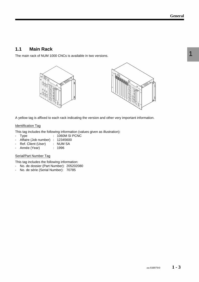
11.1 Main RackThe main rack of NUM 1000 CNCs is available in two versions.
A yellow tag is affixed to each rack indicating the version and other very important information.
Identification Tag
This tag includes the following information (values given as illustration):- Type : 1060M SI PCNC- Affaire (Job number) : 12345600- Ref. Client (User) : NUM SA- Année (Year) : 1996
Serial/Part Number Tag
This tag includes the following information:- No. de dossier (Part Number): 205202080- No. de série (Serial Number): 70785
1 - 4 en-938979/0
Affaire Number
Whenever you need to contact NUM for service or parts information, you will be asked for the 8-digit Affaire Number,used by NUM to keep track of all the systems sold throughout the world. All the pertinent information on 1060 systemsis available from Num.
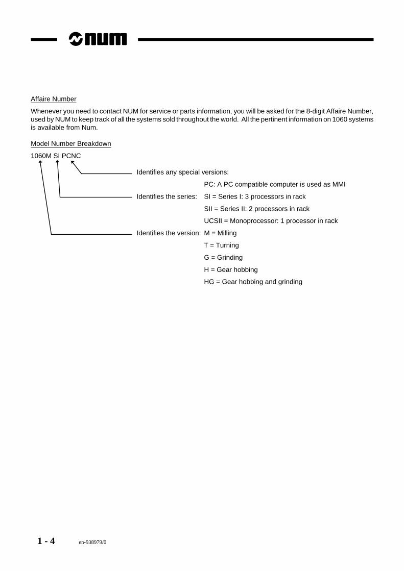
Model Number Breakdown
1060M SI PCNC
Identifies any special versions:
PC: A PC compatible computer is used as MMI
Identifies the series: SI = Series I: 3 processors in rack
SII = Series II: 2 processors in rack
UCSII = Monoprocessor: 1 processor in rack
Identifies the version: M = Milling
T = Turning
G = Grinding
H = Gear hobbing
HG = Gear hobbing and grinding
en-938979/0 1 - 5
General
11.2 Differences Between VersionsThe entire family of NUM 1000 CNCs is based on Motorola MC68020 microprocessors and associated chipsets. Thedifferences between series are a result of the number of processors in each series. The dialogue functionality (MMI)is identical on all systems, which differ only by the hardware.
The main rack assembly is available in two sizes: 19" and 12". Series I generally uses a 19" rack and Series II andUCSII a 12" rack, but this is not always the case. Always check the Affaire Number on the ID tag. The main componentsare briefly described below. For more detailed information on the sizes and conditions of use, refer to InstallationManuals 938816, 938938 and 938977.
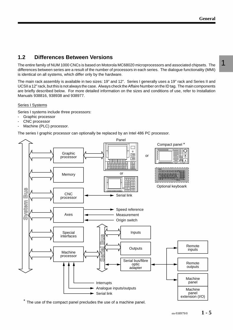
Series I Systems
Series I systems include three processors:- Graphic processor- CNC processor- Machine (PLC) processor.
The series I graphic processor can optionally be replaced by an Intel 486 PC processor.
Graphicprocessor
Memory
CNCprocessor
Axes
Specialinterfaces
Machineprocessor
Serial link
Speed referenceMeasurementOrigin switch
InterruptsAnalogue inputs/outputsSerial link
Inputs
Remoteoutputs
Sys
tem
Bu
s
Ser
ial B
us
Serial bus/fibreoptic
adapter
RemoteinputsOutputs
Machinepanel
Machinepanel
extension (I/O)
Compact panel ∗
Optional keyboark
Panel
or
or
∗ The use of the compact panel precludes the use of a machine panel.
1 - 6 en-938979/0
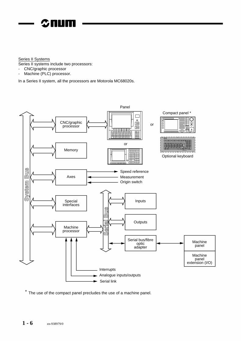
Series II SystemsSeries II systems include two processors:- CNC/graphic processor- Machine (PLC) processor.
In a Series II system, all the processors are Motorola MC68020s.
CNC/graphicprocessor
Memory
Axes
Specialinterfaces
Machineprocessor
Speed referenceMeasurementOrigin switch
InputsSys
tem
Bu
s
Ser
ial B
us
Serial bus/fibreoptic
adapter
Outputs
Machinepanel
Machinepanel
extension (I/O)
Compact panel ∗
Optional keyboard
Panel
or
or
∗ The use of the compact panel precludes the use of a machine panel.
Serial link
Interrupts
Analogue inputs/outputs
en-938979/0 1 - 7
General
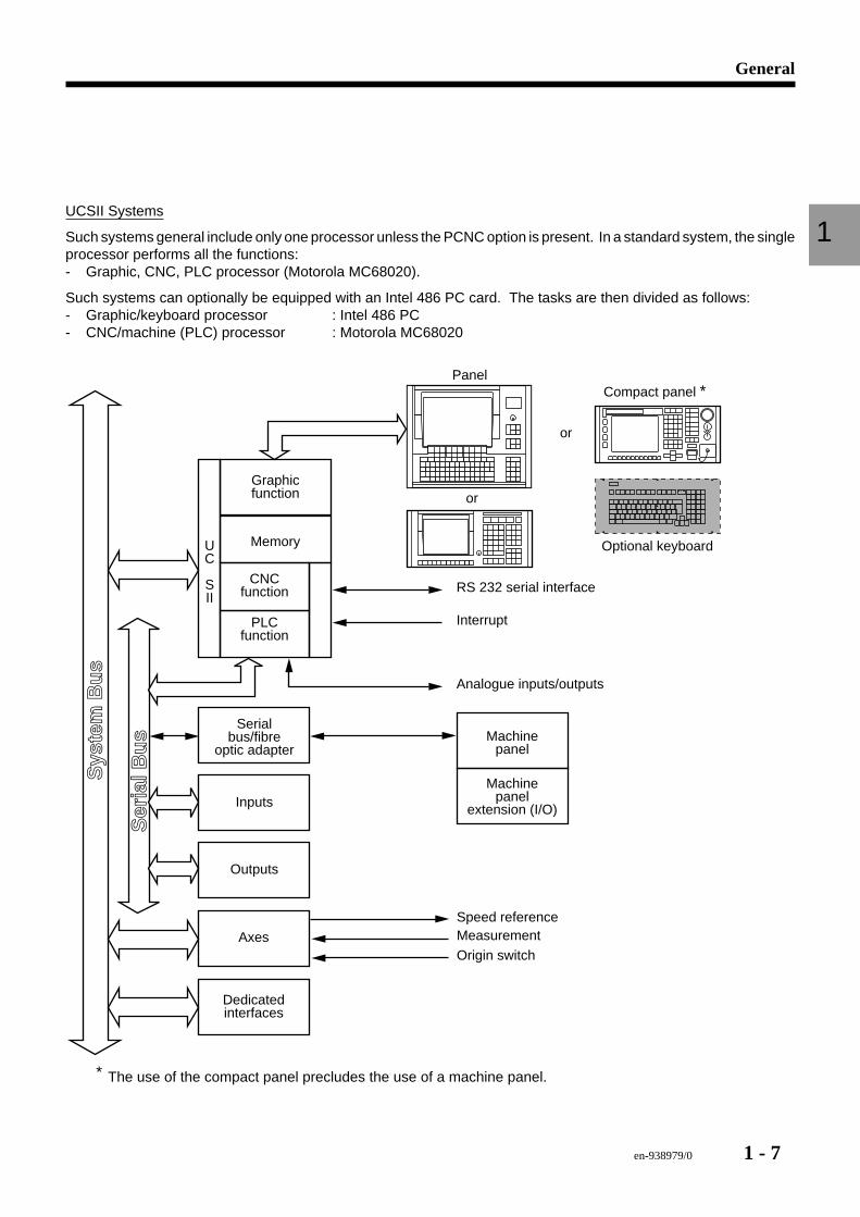
1UCSII Systems
Such systems general include only one processor unless the PCNC option is present. In a standard system, the singleprocessor performs all the functions:- Graphic, CNC, PLC processor (Motorola MC68020).
Such systems can optionally be equipped with an Intel 486 PC card. The tasks are then divided as follows:- Graphic/keyboard processor : Intel 486 PC- CNC/machine (PLC) processor : Motorola MC68020
Graphicfunction
Memory
CNCfunction
Axes
Dedicatedinterfaces
PLCfunction
RS 232 serial interface
Inputs
Sys
tem
Bu
s
Ser
ial B
us
Outputs
Analogue inputs/outputs
Interrupt
Serialbus/fibre
optic adapterMachine
panel
Machinepanel
extension (I/O)
UC
SII
Compact panel ∗
Optional keyboard
Panel
or
or
∗ The use of the compact panel precludes the use of a machine panel.
Speed reference
Origin switchMeasurement
1 - 8 en-938979/0
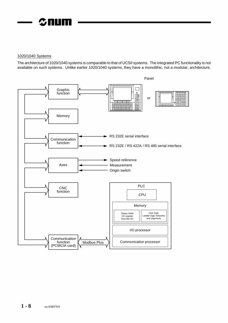
1020/1040 Systems
The architecture of 1020/1040 systems is comparable to that of UCSII systems. The integrated PC functionality is notavailable on such systems. Unlike earlier 1020/1040 systems, they have a monolithic, not a modular, architecture.
Graphicfunction
Memory
Communicationfunction
Axes
CNCfunction
Communicationfunction
(PCMCIA card)
RS 232E serial interface
RS 232E / RS 422A / RS 485 serial interface
Speed referenceMeasurementOrigin switch
Panel
or
CPU
I/O processor
Communication processor
Status RAMI/O registerDiscrete I/O
User logicLadder logic networks
and segments
Memory
PLC
Modbus Plus
en-938979/0 1 - 9
General
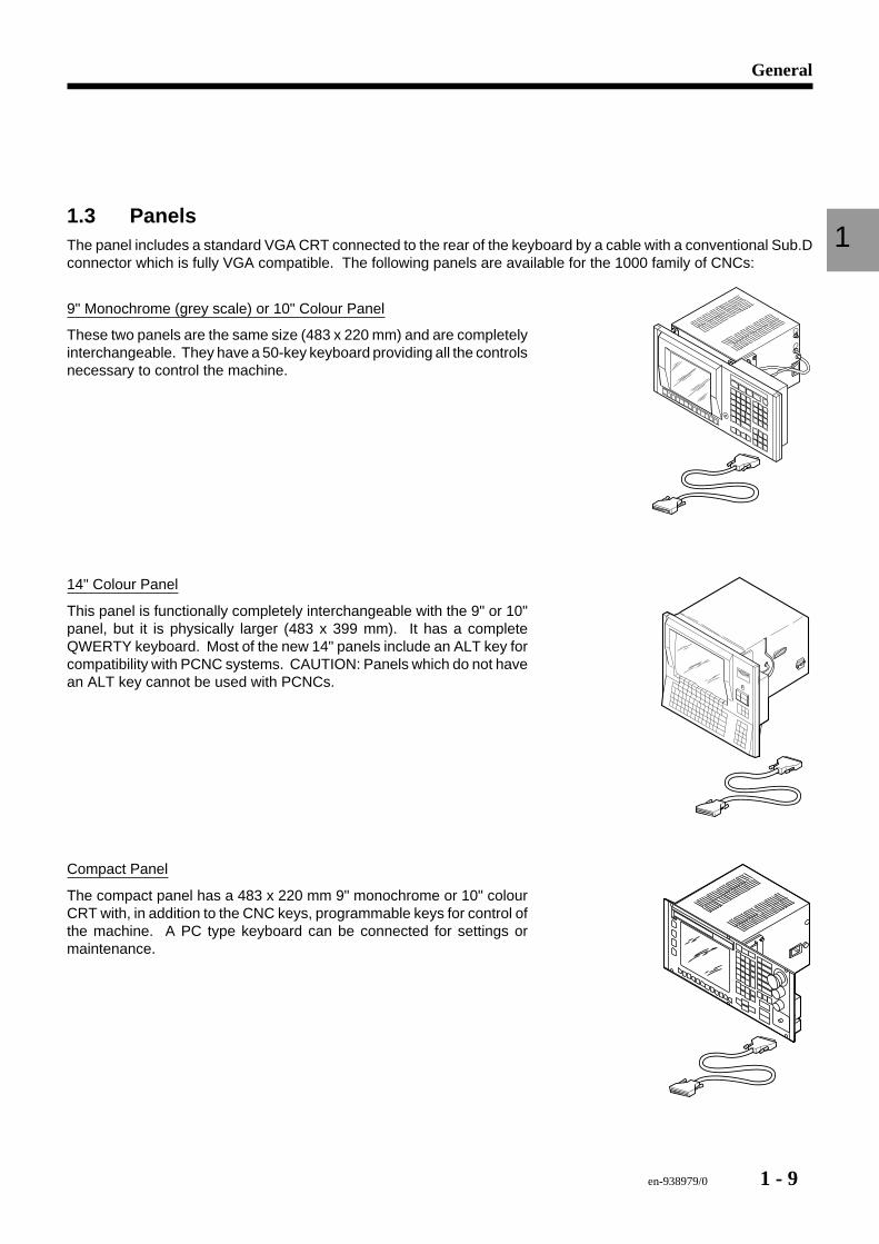
11.3 PanelsThe panel includes a standard VGA CRT connected to the rear of the keyboard by a cable with a conventional Sub.Dconnector which is fully VGA compatible. The following panels are available for the 1000 family of CNCs:
9" Monochrome (grey scale) or 10" Colour Panel
These two panels are the same size (483 x 220 mm) and are completelyinterchangeable. They have a 50-key keyboard providing all the controlsnecessary to control the machine.
14" Colour Panel
This panel is functionally completely interchangeable with the 9" or 10"panel, but it is physically larger (483 x 399 mm). It has a completeQWERTY keyboard. Most of the new 14" panels include an ALT key forcompatibility with PCNC systems. CAUTION: Panels which do not havean ALT key cannot be used with PCNCs.
Compact Panel
The compact panel has a 483 x 220 mm 9" monochrome or 10" colourCRT with, in addition to the CNC keys, programmable keys for control ofthe machine. A PC type keyboard can be connected for settings ormaintenance.
1 - 10 en-938979/0
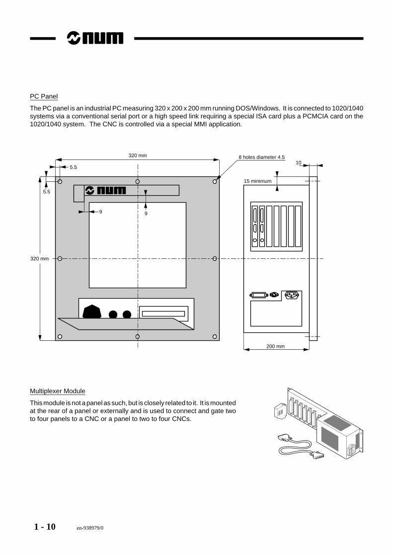
PC Panel
The PC panel is an industrial PC measuring 320 x 200 x 200 mm running DOS/Windows. It is connected to 1020/1040systems via a conventional serial port or a high speed link requiring a special ISA card plus a PCMCIA card on the1020/1040 system. The CNC is controlled via a special MMI application.
200 mm
8 holes diameter 4.5
15 minimum
105.5
9
5.5
9
320 mm
320 mm
Multiplexer Module
This module is not a panel as such, but is closely related to it. It is mountedat the rear of a panel or externally and is used to connect and gate twoto four panels to a CNC or a panel to two to four CNCs.
en-938979/0 1 - 11
General
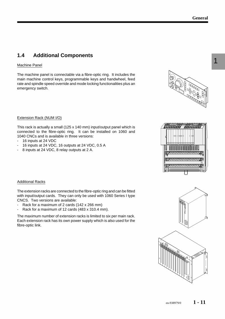
11.4 Additional Components
Machine Panel
The machine panel is connectable via a fibre-optic ring. It includes themain machine control keys, programmable keys and handwheel, feedrate and spindle speed override and mode locking functionalities plus anemergency switch.
Extension Rack (NUM I/O)
This rack is actually a small (125 x 140 mm) input/output panel which isconnected to the fibre-optic ring. It can be installed on 1060 and1040 CNCs and is available in three versions:- 16 inputs at 24 VDC- 16 inputs at 24 VDC, 16 outputs at 24 VDC, 0.5 A- 8 inputs at 24 VDC, 8 relay outputs at 2 A.
Additional Racks
The extension racks are connected to the fibre-optic ring and can be fittedwith input/output cards. They can only be used with 1060 Series I typeCNCS. Two versions are available:- Rack for a maximum of 2 cards (142 x 266 mm)- Rack for a maximum of 12 cards (483 x 310.4 mm).
The maximum number of extension racks is limited to six per main rack.Each extension rack has its own power supply which is also used for thefibre-optic link.
1 - 12 en-938979/0
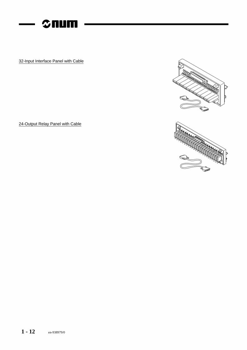
32-Input Interface Panel with Cable
24-Output Relay Panel with Cable
en-938979/0 2 - 1
System Overview
2
2 System Overview
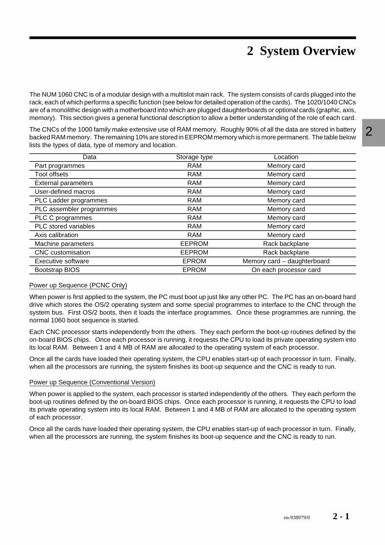
The NUM 1060 CNC is of a modular design with a multislot main rack. The system consists of cards plugged into therack, each of which performs a specific function (see below for detailed operation of the cards). The 1020/1040 CNCsare of a monolithic design with a motherboard into which are plugged daughterboards or optional cards (graphic, axis,memory). This section gives a general functional description to allow a better understanding of the role of each card.
The CNCs of the 1000 family make extensive use of RAM memory. Roughly 90% of all the data are stored in batterybacked RAM memory. The remaining 10% are stored in EEPROM memory which is more permanent. The table belowlists the types of data, type of memory and location.
Data Storage type LocationPart programmes RAM Memory cardTool offsets RAM Memory cardExternal parameters RAM Memory cardUser-defined macros RAM Memory cardPLC Ladder programmes RAM Memory cardPLC assembler programmes RAM Memory cardPLC C programmes RAM Memory cardPLC stored variables RAM Memory cardAxis calibration RAM Memory cardMachine parameters EEPROM Rack backplaneCNC customisation EEPROM Rack backplaneExecutive software EPROM Memory card – daughterboardBootstrap BIOS EPROM On each processor card
Power up Sequence (PCNC Only)
When power is first applied to the system, the PC must boot up just like any other PC. The PC has an on-board harddrive which stores the OS/2 operating system and some special programmes to interface to the CNC through thesystem bus. First OS/2 boots, then it loads the interface programmes. Once these programmes are running, thenormal 1060 boot sequence is started.
Each CNC processor starts independently from the others. They each perform the boot-up routines defined by theon-board BIOS chips. Once each processor is running, it requests the CPU to load its private operating system intoits local RAM. Between 1 and 4 MB of RAM are allocated to the operating system of each processor.
Once all the cards have loaded their operating system, the CPU enables start-up of each processor in turn. Finally,when all the processors are running, the system finishes its boot-up sequence and the CNC is ready to run.
Power up Sequence (Conventional Version)
When power is applied to the system, each processor is started independently of the others. They each perform theboot-up routines defined by the on-board BIOS chips. Once each processor is running, it requests the CPU to loadits private operating system into its local RAM. Between 1 and 4 MB of RAM are allocated to the operating systemof each processor.
Once all the cards have loaded their operating system, the CPU enables start-up of each processor in turn. Finally,when all the processors are running, the system finishes its boot-up sequence and the CNC is ready to run.

2 - 2 en-938979/0
en-938979/0 3 - 1
Power Supplies
3
3 Power Supplies
3.1 Rack Power Supply 3 - 33.1.1 Voltage Level Indicators 3 - 43.1.2 PWR FAIL LED 3 - 43.1.3 RaZ (Reset) Button 3 - 43.1.4 Fibre-Optic Ports 3 - 5
3.2 Panel Power Supply 3 - 6
3.3 Keyboard Power Supply 3 - 7

3 - 2 en-938979/0
en-938979/0 3 - 3
Power Supplies
3
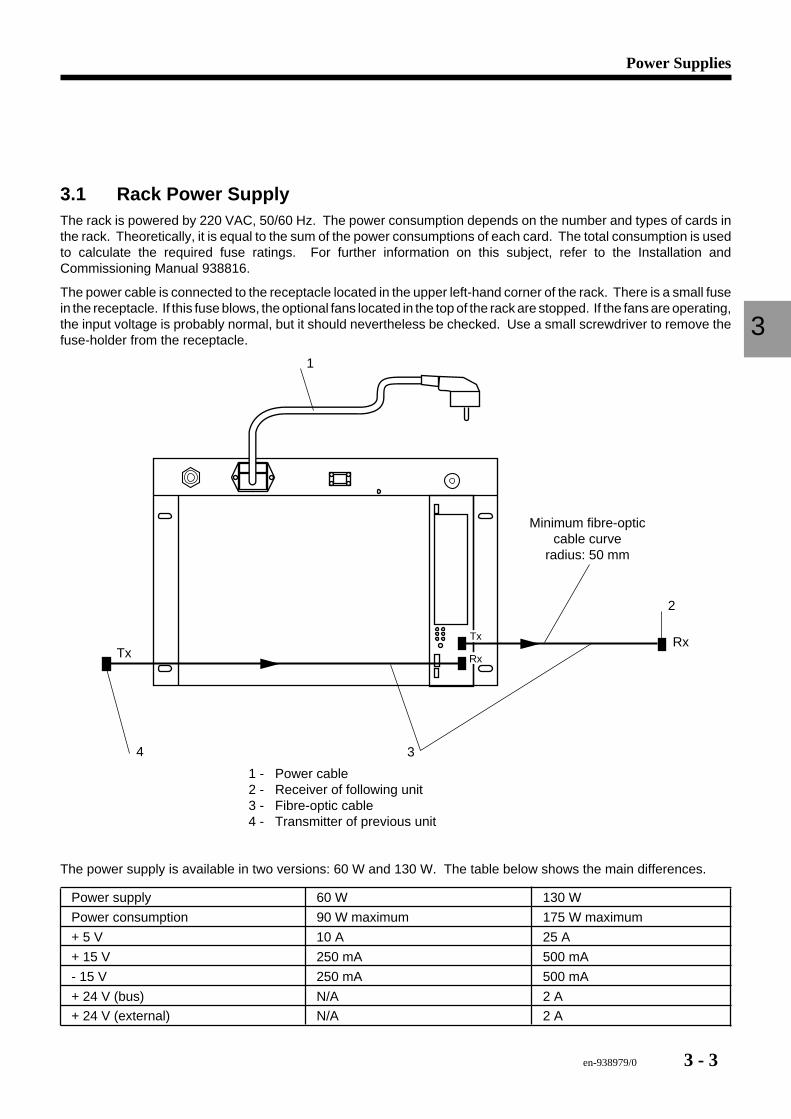
3.1 Rack Power SupplyThe rack is powered by 220 VAC, 50/60 Hz. The power consumption depends on the number and types of cards inthe rack. Theoretically, it is equal to the sum of the power consumptions of each card. The total consumption is usedto calculate the required fuse ratings. For further information on this subject, refer to the Installation andCommissioning Manual 938816.
The power cable is connected to the receptacle located in the upper left-hand corner of the rack. There is a small fusein the receptacle. If this fuse blows, the optional fans located in the top of the rack are stopped. If the fans are operating,the input voltage is probably normal, but it should nevertheless be checked. Use a small screwdriver to remove thefuse-holder from the receptacle.
Tx
RxTxRx
Minimum fibre-opticcable curve
radius: 50 mm
34
1
2
1 - Power cable2 - Receiver of following unit3 - Fibre-optic cable4 - Transmitter of previous unit
The power supply is available in two versions: 60 W and 130 W. The table below shows the main differences.
Power supply 60 W 130 W
Power consumption 90 W maximum 175 W maximum
+ 5 V 10 A 25 A
+ 15 V 250 mA 500 mA
- 15 V 250 mA 500 mA
+ 24 V (bus) N/A 2 A
+ 24 V (external) N/A 2 A
3 - 4 en-938979/0
3.1.1 Voltage Level Indicators
+24VI
+15V
+5V
+24VE
-15V
Pw Fail
RaZEm
F/O
24 VE0 VE
Alim
Rec
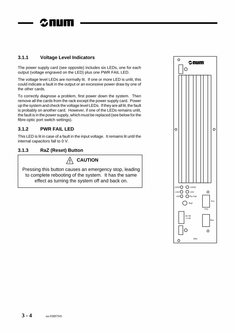
The power supply card (see opposite) includes six LEDs, one for eachoutput (voltage engraved on the LED) plus one PWR FAIL LED.
The voltage level LEDs are normally lit. If one or more LED is unlit, thiscould indicate a fault in the output or an excessive power draw by one ofthe other cards.
To correctly diagnose a problem, first power down the system. Thenremove all the cards from the rack except the power supply card. Powerup the system and check the voltage level LEDs. If they are all lit, the faultis probably on another card. However, if one of the LEDs remains unlit,the fault is in the power supply, which must be replaced (see below for thefibre-optic port switch settings).
3.1.2 PWR FAIL LED
This LED is lit in case of a fault in the input voltage. It remains lit until theinternal capacitors fall to 0 V.
3.1.3 RaZ (Reset) Button
! CAUTION
Pressing this button causes an emergency stop, leadingto complete rebooting of the system. It has the same
effect as turning the system off and back on.
en-938979/0 3 - 5
Power Supplies
3
3.1.4 Fibre-Optic Ports
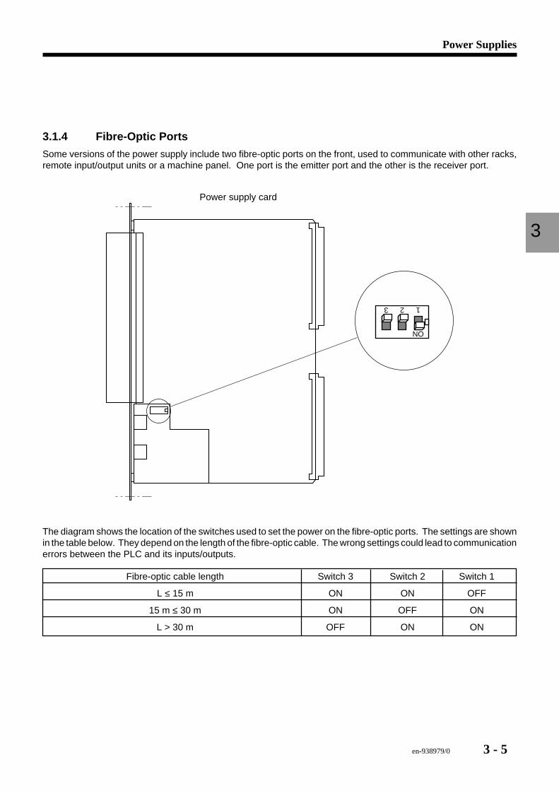
Some versions of the power supply include two fibre-optic ports on the front, used to communicate with other racks,remote input/output units or a machine panel. One port is the emitter port and the other is the receiver port.
Power supply card
ON
123
The diagram shows the location of the switches used to set the power on the fibre-optic ports. The settings are shownin the table below. They depend on the length of the fibre-optic cable. The wrong settings could lead to communicationerrors between the PLC and its inputs/outputs.
Fibre-optic cable length Switch 3 Switch 2 Switch 1
L ≤ 15 m ON ON OFF
15 m ≤ 30 m ON OFF ON
L > 30 m OFF ON ON
3 - 6 en-938979/0
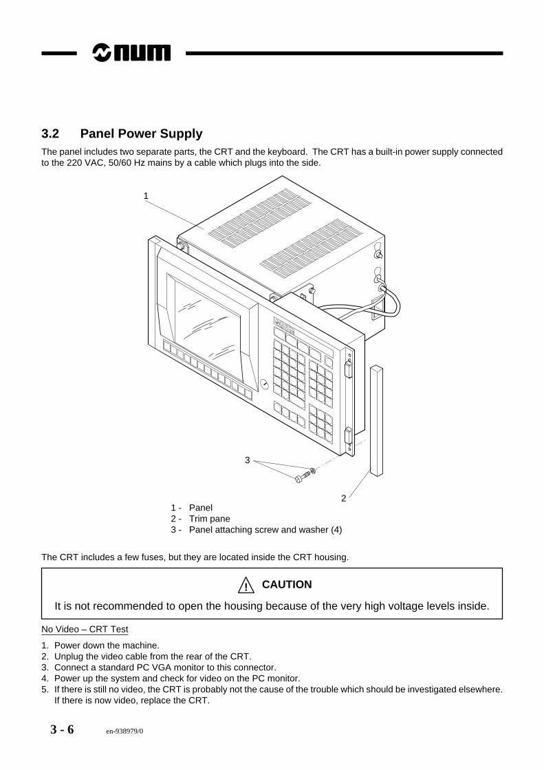
3.2 Panel Power SupplyThe panel includes two separate parts, the CRT and the keyboard. The CRT has a built-in power supply connectedto the 220 VAC, 50/60 Hz mains by a cable which plugs into the side.
2
1
3
1 - Panel2 - Trim pane3 - Panel attaching screw and washer (4)
The CRT includes a few fuses, but they are located inside the CRT housing.
! CAUTION
It is not recommended to open the housing because of the very high voltage levels inside.
No Video – CRT Test
1. Power down the machine.2. Unplug the video cable from the rear of the CRT.3. Connect a standard PC VGA monitor to this connector.4. Power up the system and check for video on the PC monitor.5. If there is still no video, the CRT is probably not the cause of the trouble which should be investigated elsewhere.
If there is now video, replace the CRT.
en-938979/0 3 - 7
Power Supplies
3
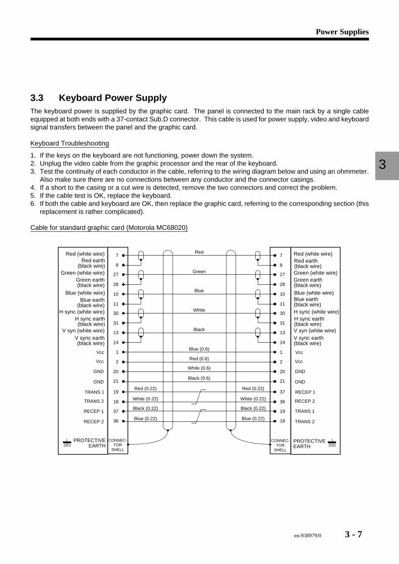
3.3 Keyboard Power SupplyThe keyboard power is supplied by the graphic card. The panel is connected to the main rack by a single cableequipped at both ends with a 37-contact Sub.D connector. This cable is used for power supply, video and keyboardsignal transfers between the panel and the graphic card.
Keyboard Troubleshooting
1. If the keys on the keyboard are not functioning, power down the system.2. Unplug the video cable from the graphic processor and the rear of the keyboard.3. Test the continuity of each conductor in the cable, referring to the wiring diagram below and using an ohmmeter.
Also make sure there are no connections between any conductor and the connector casings.4. If a short to the casing or a cut wire is detected, remove the two connectors and correct the problem.5. If the cable test is OK, replace the keyboard.6. If both the cable and keyboard are OK, then replace the graphic card, referring to the corresponding section (this
replacement is rather complicated).
Cable for standard graphic card (Motorola MC68020)
CONNEC-TOR
SHELL
1Vcc
2
20
Vcc
GND
GND
31
13
14
10
11
30
8
27
28
7
1 Vcc
2
20
Vcc
GND
GND
31
13
14
10
11
30
8
27
28
7
CONNEC-TOR
SHELL
Red
Green
Blue
White
Black
Blue (0.6)
Red (0.6)
White (0.6)
Black (0.6)21 21
19TRANS 1
18
37
TRANS 2
RECEP 1
RECEP 2
37 RECEP 1
36
19
RECEP 2
TRANS 1
TRANS 236 18
Red (0.22)
White (0.22)
Black (0.22)
Blue (0.22)
Red (0.22)
White (0.22)
Black (0.22)
Blue (0.22)
H sync earth(black wire)
V syn (white wire)V sync earth(black wire)
Blue (white wire)Blue earth
(black wire)H sync (white wire)
Red earth(black wire)
Green (white wire)Green earth(black wire)
Red (white wire)
H sync earth(black wire)V syn (white wire)V sync earth(black wire)
Blue (white wire)Blue earth(black wire)H sync (white wire)
Red earth(black wire)Green (white wire)Green earth(black wire)
Red (white wire)
PROTECTIVEEARTH
PROTECTIVEEARTH
3 - 8 en-938979/0
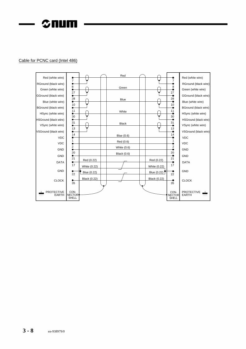
Cable for PCNC card (Intel 486)
CON-NECTORSHELL
PROTECTIVEEARTH
1VDC
2
20
VDC
GND
GND
31HSGround (black wiire)
13
14
VSync (white wire)
VSGround (black wire)
10Blue (white wire)
11
30
BGround (black wire)
HSync (white wire)
8RGround (black wire)
27
28
Green (white wire)
GGround (black wire)
7Red (white wire)
1VDC
2
20
VDC
GND
GND
31HSGround (black wire)
13
14
VSync (white wire)
VSGround (black wire)
10Blue (white wire)
11
30
BGround (black wire)
HSync (white wire)
8RGround (black wire)
27
28
Green (white wire)
GGround (black wire)
7Red (white wire)
CON-NECTORSHELL
PROTECTIVEEARTH
Red
Green
Blue
White
Black
Blue (0.6)
Red (0.6)
White (0.6)
Black (0.6)
21 21
17DATA
22GND
CLOCK
17DATA
22GND
CLOCK35 35
Red (0.22)
White (0.22)
Blue (0.22)
Black (0.22)
Red (0.22)
White (0.22)
Blue (0.22)
Black (0.22)
en-938979/0 4 - 1
Processors
4
4 Processors
4.1 CNC Processor 4 - 34.1.1 Version Identification 4 - 34.1.2 LEDs 4 - 44.1.3 Ports 4 - 44.1.4 Card Location 4 - 54.1.5 Replacing the Card 4 - 6
4.2 Machine (PLC) Processor 4 - 74.2.1 Version Identification 4 - 74.2.2 LEDs 4 - 84.2.3 Ports 4 - 84.2.4 Card Location 4 - 114.2.5 Replacing the Card 4 - 13
4.3 Graphic Processor 4 - 144.3.1 Version Identification 4 - 144.3.2 LEDs 4 - 154.3.3 Daughterboards 4 - 154.3.4 Ports 4 - 164.3.5 Card Location 4 - 174.3.6 Replacing the Card 4 - 17
4.4 UCSII Monoprocessor 4 - 184.4.1 Version Identification 4 - 184.4.2 LEDs 4 - 194.4.3 Ports 4 - 194.4.4 Card Location 4 - 214.4.5 Replacing the Card 4 - 22
4.5 PCNC Processor 4 - 234.5.1 Version Identification 4 - 234.5.2 LEDs 4 - 244.5.3 Ports 4 - 244.5.4 Card Location 4 - 274.5.5 Pre-replacement Diagnostics 4 - 284.5.6 Replacing the Card Alone 4 - 294.5.7 Card and Hard Drive Replacement
Procedure 4 - 294.5.8 CMOS RAM Configuration Access 4 - 304.5.9 Replacing the Battery 4 - 324.5.10 Adding or Removing a DRAM Memory
Module 4 - 334.5.11 Diskette Drive 4 - 35
4.6 1020/1040 Motherboard 4 - 394.6.1 Version Identification 4 - 394.6.2 LEDs 4 - 404.6.3 Ports 4 - 404.6.4 Characteristics 4 - 434.6.5 Replacing the Card 4 - 444.6.6 Replacing the Battery 4 - 454.6.7 Adding an SRAM Module 4 - 46

4 - 2 en-938979/0
en-938979/0 4 - 3
Processors
4
Depending on the type, the system is equipped with one or more processors. Chapter 1 explains how to determinethe number of processors in a given system.
This section contains a detailed description of the cards, their functions, connectors, and diagnostic aids. It alsoexplains how to replace the processors if necessary.
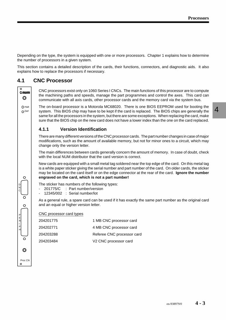
4.1 CNC Processor
Halt
Def
DNC
PERIPH
Proc CN
CNC processors exist only on 1060 Series I CNCs. The main functions of this processor are to computethe machining paths and speeds, manage the part programmes and control the axes. This card cancommunicate with all axis cards, other processor cards and the memory card via the system bus.
The on-board processor is a Motorola MC68020. There is one BIOS EEPROM used for booting thesystem. This BIOS chip may have to be kept if the card is replaced. The BIOS chips are generally thesame for all the processors in the system, but there are some exceptions. When replacing the card, makesure that the BIOS chip on the new card does not have a lower index than the one on the card replaced.
4.1.1 Version Identification
There are many different versions of the CNC processor cards. The part number changes in case of majormodifications, such as the amount of available memory, but not for minor ones to a circuit, which maychange only the version letter.
The main differences between cards generally concern the amount of memory. In case of doubt, checkwith the local NUM distributor that the card version is correct.
New cards are equipped with a small metal tag soldered near the top edge of the card. On this metal tagis a white paper sticker giving the serial number and part number of the card. On older cards, the stickermay be located on the card itself or on the edge connector at the rear of the card. Ignore the numberengraved on the card, which is not a part number!
The sticker has numbers of the following types:- 201775/C : Part number/version- 12345/002 : Serial number/lot
As a general rule, a spare card can be used if it has exactly the same part number as the original cardand an equal or higher version letter.
CNC processor card types
204201775 1 MB CNC processor card
204202771 4 MB CNC processor card
204203288 Referee CNC processor card
204203484 V2 CNC processor card
4 - 4 en-938979/0
! CAUTION
Never replace a card by a card with a different part number or a lower versionletter without first consulting NUM Technical Support.
4.1.2 LEDs
The front plate of this card includes two red LEDs, marked DEF and HALT. Under normal operating conditions, neitherLED is lit, except during start-up, when they may come on briefly.
DEF LED
If the DEF LED is lit steady, the processor card is no longer operating. It may be a hardware or a software failure, butthe most frequent cause is a problem with the software or memory. It is then necessary to reboot the system. ThisLED is sometimes lit during boot-up.
HALT LED
If the HALT LED is lit steady, the processor has stopped generally due to a fault on the card. However, this is not anabsolute rule, and in some rare cases, the fault may be due to an outside cause.
Replace the card and reboot the system. If the system hangs on reboot or stops later with the same fault, reinstall theoriginal card, which was not the cause of the failure, and look elsewhere for the cause.
4.1.3 Ports
There are two communication ports available on the front plate.
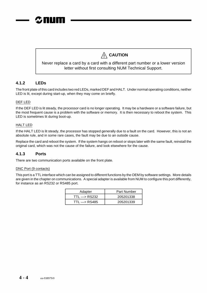
DNC Port (9 contacts)
This port is a TTL interface which can be assigned to different functions by the OEM by software settings. More detailsare given in the chapter on communications. A special adapter is available from NUM to configure this port differently,for instance as an RS232 or RS485 port.
Adapter Part Number
TTL —> RS232 205201338
TTL —> RS485 205201339
en-938979/0 4 - 5
Processors
4
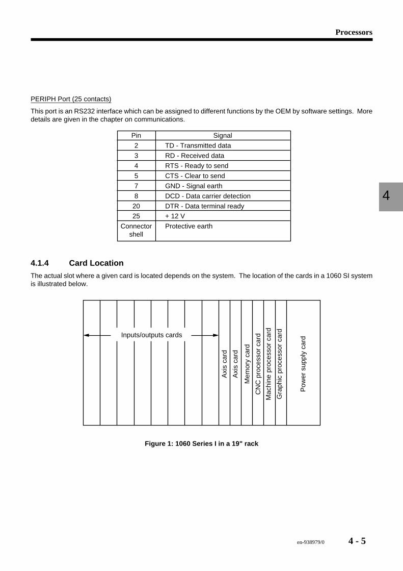
PERIPH Port (25 contacts)
This port is an RS232 interface which can be assigned to different functions by the OEM by software settings. Moredetails are given in the chapter on communications.
Pin Signal
2 TD - Transmitted data
3 RD - Received data
4 RTS - Ready to send
5 CTS - Clear to send
7 GND - Signal earth
8 DCD - Data carrier detection
20 DTR - Data terminal ready
25 + 12 V
Connector Protective earthshell
4.1.4 Card Location
The actual slot where a given card is located depends on the system. The location of the cards in a 1060 SI systemis illustrated below.
Mac
hine
pro
cess
or c
ard
Gra
phic
pro
cess
or c
ard
Pow
er s
uppl
y ca
rd
CN
C p
roce
ssor
car
d
Mem
ory
card
Axi
s ca
rd
Axi
s ca
rd
Inputs/outputs cards
Figure 1: 1060 Series I in a 19" rack
4 - 6 en-938979/0
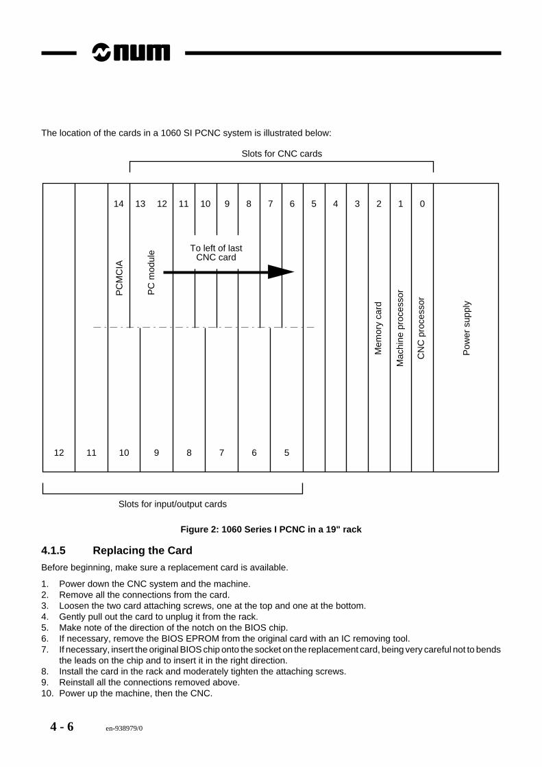
The location of the cards in a 1060 SI PCNC system is illustrated below:
12 11 10 8 7 6 5
11
9
121314 10 9 8 7 6 5 4 3 2 1 0
Slots for CNC cards
Slots for input/output cards
Mac
hine
pro
cess
or
CN
C p
roce
ssor
Pow
er s
uppl
y
Mem
ory
card
PC
mod
ule
PC
MC
IA
To left of lastCNC card
Figure 2: 1060 Series I PCNC in a 19" rack
4.1.5 Replacing the Card
Before beginning, make sure a replacement card is available.
1. Power down the CNC system and the machine.2. Remove all the connections from the card.3. Loosen the two card attaching screws, one at the top and one at the bottom.4. Gently pull out the card to unplug it from the rack.5. Make note of the direction of the notch on the BIOS chip.6. If necessary, remove the BIOS EPROM from the original card with an IC removing tool.7. If necessary, insert the original BIOS chip onto the socket on the replacement card, being very careful not to bends
the leads on the chip and to insert it in the right direction.8. Install the card in the rack and moderately tighten the attaching screws.9. Reinstall all the connections removed above.10. Power up the machine, then the CNC.
en-938979/0 4 - 7
Processors
4
4.2 Machine (PLC) Processor
Halt
Def
SERIE
Proc Mach
RS 232422/485
CAN/CNA
IT.EXT
RS 232
SERIE
Machine processors are found on 1060 Series I and Series II systems. The main functions of thisprocessor are to process the PLC programmes and control the discrete inputs and outputs. This cardcan communicate with all the other processor cards, the power supply (for the serial fibre-optic link) andthe memory card via the system bus.
The on-board processor is a Motorola MC68020. There is one BIOS EEPROM used for booting thesystem. This BIOS chip may have to be kept if the card is replaced. The BIOS chips are generally thesame for all the processors in the system, but there are some exceptions. When replacing the card, makesure that the BIOS chip on the new card does not have a lower index than the one on the card replaced.
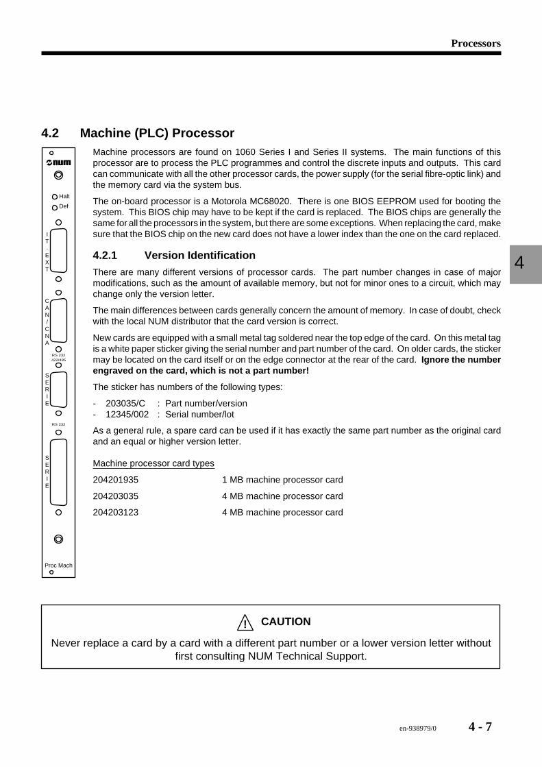
4.2.1 Version IdentificationThere are many different versions of processor cards. The part number changes in case of majormodifications, such as the amount of available memory, but not for minor ones to a circuit, which maychange only the version letter.
The main differences between cards generally concern the amount of memory. In case of doubt, checkwith the local NUM distributor that the card version is correct.
New cards are equipped with a small metal tag soldered near the top edge of the card. On this metal tagis a white paper sticker giving the serial number and part number of the card. On older cards, the stickermay be located on the card itself or on the edge connector at the rear of the card. Ignore the numberengraved on the card, which is not a part number!
The sticker has numbers of the following types:
- 203035/C : Part number/version- 12345/002 : Serial number/lot
As a general rule, a spare card can be used if it has exactly the same part number as the original cardand an equal or higher version letter.
Machine processor card types
204201935 1 MB machine processor card
204203035 4 MB machine processor card
204203123 4 MB machine processor card
! CAUTION
Never replace a card by a card with a different part number or a lower version letter withoutfirst consulting NUM Technical Support.
4 - 8 en-938979/0
4.2.2 LEDs
The front plate of this card includes two red LEDs, marked DEF and HALT. Under normal operating conditions, neitherLED is lit, except during start-up, when they may come on briefly.
DEF LED
If the DEF LED is lit steady, the processor card is no longer operating. It may be a hardware or a software failure, butthe most frequent cause is a problem with the software or memory. It is then necessary to reboot the system.
HALT LED
If the HALT LED is lit steady, the processor has stopped generally due to a fault on the card. However, the fault is notnecessarily on the card.
Replace the card and reboot the system. If the system hangs on reboot or stops later with the same fault, reinstall theoriginal card, which was not the cause of the failure, and look elsewhere for the cause.
4.2.3 Ports
There are four ports available on the front plate, two dedicated to I/O and two to communications.
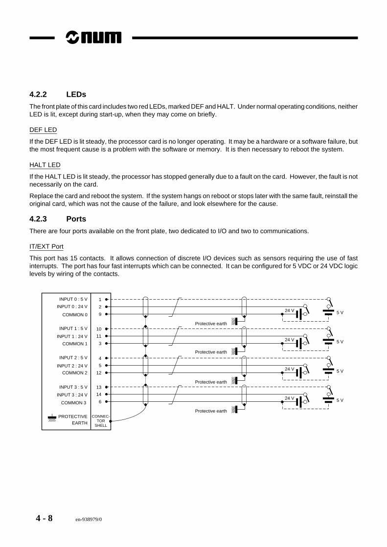
IT/EXT Port
This port has 15 contacts. It allows connection of discrete I/O devices such as sensors requiring the use of fastinterrupts. The port has four fast interrupts which can be connected. It can be configured for 5 VDC or 24 VDC logiclevels by wiring of the contacts.
1
CONNEC-TOR
SHELL
2
9
10
11
3
4
5
12
13
14
6
24 V 5 V
24 V 5 V
24 V 5 V
24 V 5 V
INPUT 0 : 5 V
Protective earth
INPUT 0 : 24 V
COMMON 0
INPUT 1 : 5 V
INPUT 1 : 24 V
COMMON 1
INPUT 2 : 5 V
INPUT 2 : 24 V
COMMON 2
INPUT 3 : 5 V
INPUT 3 : 24 V
COMMON 3
PROTECTIVEEARTH
Protective earth
Protective earth
Protective earth
en-938979/0 4 - 9
Processors
4
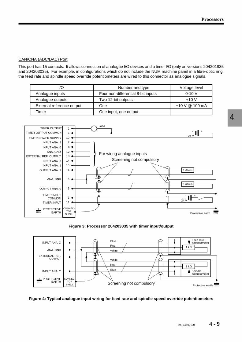
CAN/CNA (ADC/DAC) Port
This port has 15 contacts. It allows connection of analogue I/O devices and a timer I/O (only on versions 204201935and 204203035). For example, in configurations which do not include the NUM machine panel in a fibre-optic ring,the feed rate and spindle speed override potentiometers are wired to this connector as analogue signals.
I/O Number and type Voltage level
Analogue inputs Four non-differential 8-bit inputs 0-10 V
Analogue outputs Two 12-bit outputs +10 V
External reference output One +10 V @ 100 mA
Timer One input, one output
2
9
10
4
6
5
3
11
8
12
13
15
24 V
- +
2 kΩ min.
2 kΩ min.
24 V
- +
14
7
TIMER OUTPUT
TIMER INPUTCOMMON
OUTPUT ANA. 1
OUTPUT ANA. 0
ANA. GND
INPUT ANA. 0
TIMER OUTPUT COMMON
TIMER POWER SUPPLY
ANA. GND
EXTERNAL REF. OUTPUT
INPUT ANA. 1
PROTECTIVEEARTH
Load
Protective earth
INPUT ANA. 3
INPUT ANA. 2
For wiring analogue inputs
Screening not compulsory
TIMER INPUT
CONNEC-TOR
SHELL
Figure 3: Processor 204203035 with timer input/output
White
Red
Blue
CONNEC-TOR
SHELL
INPUT ANA. X
ANA. GND
EXTERNAL REF.OUTPUT
INPUT ANA. Y
PROTECTIVEEARTH
1 kΩ
1 kΩ
White
Red
Blue
Feed ratepotentiometer
Spindlepotentiometer
Protective earthScreening not compulsory
Figure 4: Typical analogue input wiring for feed rate and spindle speed override potentiometers
4 - 10 en-938979/0
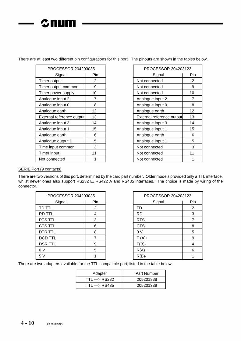
There are at least two different pin configurations for this port. The pinouts are shown in the tables below.
PROCESSOR 204203035 PROCESSOR 204203123
Signal Pin Signal Pin
Timer output 2 Not connected 2
Timer output common 9 Not connected 9
Timer power supply 10 Not connected 10
Analogue input 2 7 Analogue input 2 7
Analogue input 0 8 Analogue input 0 8
Analogue earth 12 Analogue earth 12
External reference output 13 External reference output 13
Analogue input 3 14 Analogue input 3 14
Analogue input 1 15 Analogue input 1 15
Analogue earth 6 Analogue earth 6
Analogue output 1 5 Analogue input 1 5
Time input common 3 Not connected 3
Timer input 11 Not connected 11
Not connected 1 Not connected 1
SERIE Port (9 contacts)
There are two versions of this port, determined by the card part number. Older models provided only a TTL interface,whilst newer ones also support RS232 E, RS422 A and RS485 interfaces. The choice is made by wiring of theconnector.
PROCESSOR 204203035 PROCESSOR 204203123
Signal Pin Signal Pin
TD TTL 2 TD 2
RD TTL 4 RD 3
RTS TTL 3 RTS 7
CTS TTL 6 CTS 8
DTR TTL 8 0 V 5
DCD TTL 7 T (A)+ 9
DSR TTL 9 T(B)- 4
0 V 5 R(A)+ 6
5 V 1 R(B)- 1
There are two adapters available for the TTL compatible port, listed in the table below.
Adapter Part Number
TTL —> RS232 205201338
TTL —> RS485 205201339
en-938979/0 4 - 11
Processors
4
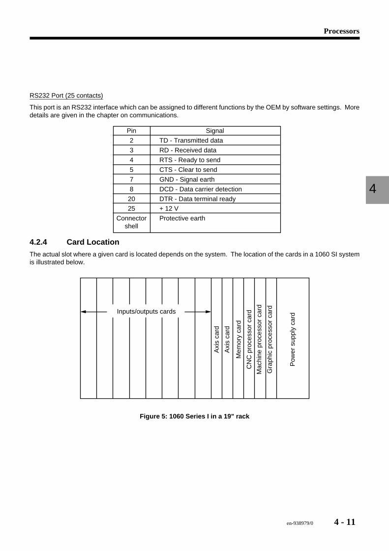
RS232 Port (25 contacts)
This port is an RS232 interface which can be assigned to different functions by the OEM by software settings. Moredetails are given in the chapter on communications.
Pin Signal
2 TD - Transmitted data
3 RD - Received data
4 RTS - Ready to send
5 CTS - Clear to send
7 GND - Signal earth
8 DCD - Data carrier detection
20 DTR - Data terminal ready
25 + 12 V
Connector Protective earthshell
4.2.4 Card Location
The actual slot where a given card is located depends on the system. The location of the cards in a 1060 SI systemis illustrated below.
Mac
hine
pro
cess
or c
ard
Gra
phic
pro
cess
or c
ard
Pow
er s
uppl
y ca
rd
CN
C p
roce
ssor
car
d
Mem
ory
card
Axi
s ca
rd
Axi
s ca
rd
Inputs/outputs cards
Figure 5: 1060 Series I in a 19" rack
4 - 12 en-938979/0
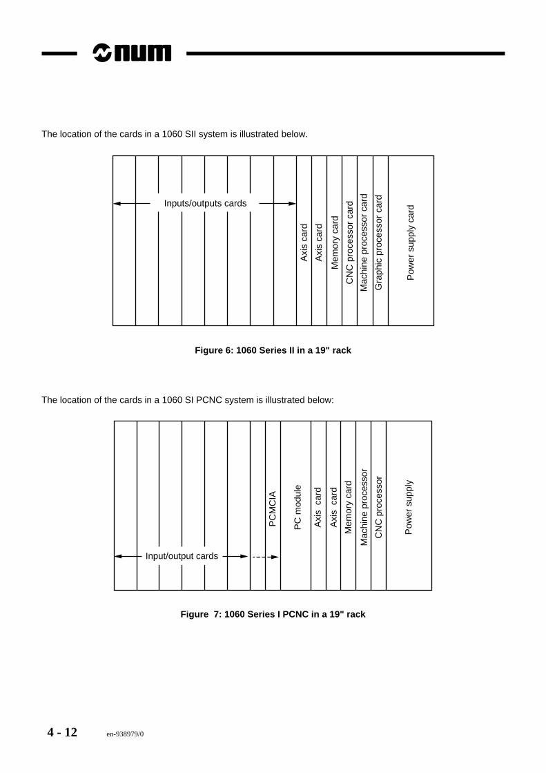
The location of the cards in a 1060 SII system is illustrated below.
Mac
hine
pro
cess
or c
ard
Gra
phic
pro
cess
or c
ard
Pow
er s
uppl
y ca
rd
CN
C p
roce
ssor
car
d
Mem
ory
card
Axi
s ca
rd
Axi
s ca
rd
Inputs/outputs cards
Figure 6: 1060 Series II in a 19" rack
The location of the cards in a 1060 SI PCNC system is illustrated below:
Mac
hine
pro
cess
or
CN
C p
roce
ssor
Pow
er s
uppl
y
Mem
ory
card
Axi
s c
ard
Axi
s c
ard
PC
mod
ule
Input/output cards
PC
MC
IA
Figure 7: 1060 Series I PCNC in a 19" rack
en-938979/0 4 - 13
Processors
4
4.2.5 Replacing the Card
Before beginning, make sure a replacement card is available.
1. Power down the CNC system and the machine.2. Remove all the connections from the card.3. Loosen the two card attaching screws, one at the top and one at the bottom.4. Gently pull out the card to unplug it from the rack.5. Make note of the direction of the notch on the BIOS chip.6. If necessary, remove the BIOS EPROM from the original card with an IC removing tool.7. If necessary, insert the original BIOS chip onto the socket on the replacement card, being very careful not to bends
the leads on the chip and to insert it in the right direction.8. Install the card in the rack and moderately tighten the attaching screws.9. Reinstall all the connections removed above.10. Power up the machine, then the CNC.
4 - 14 en-938979/0
4.3 Graphic Processor
Halt
Def
Proc Graph
LIAISON
PUPITRE
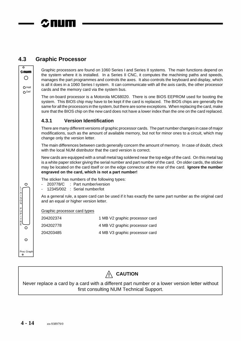
Graphic processors are found on 1060 Series I and Series II systems. The main functions depend onthe system where it is installed. In a Series II CNC, it computes the machining paths and speeds,manages the part programmes and controls the axes. It also controls the keyboard and display, whichis all it does in a 1060 Series I system. It can communicate with all the axis cards, the other processorcards and the memory card via the system bus.
The on-board processor is a Motorola MC68020. There is one BIOS EEPROM used for booting thesystem. This BIOS chip may have to be kept if the card is replaced. The BIOS chips are generally thesame for all the processors in the system, but there are some exceptions. When replacing the card, makesure that the BIOS chip on the new card does not have a lower index than the one on the card replaced.
4.3.1 Version Identification
There are many different versions of graphic processor cards. The part number changes in case of majormodifications, such as the amount of available memory, but not for minor ones to a circuit, which maychange only the version letter.
The main differences between cards generally concern the amount of memory. In case of doubt, checkwith the local NUM distributor that the card version is correct.
New cards are equipped with a small metal tag soldered near the top edge of the card. On this metal tagis a white paper sticker giving the serial number and part number of the card. On older cards, the stickermay be located on the card itself or on the edge connector at the rear of the card. Ignore the numberengraved on the card, which is not a part number!
The sticker has numbers of the following types:- 203778/C : Part number/version- 12345/002 : Serial number/lot
As a general rule, a spare card can be used if it has exactly the same part number as the original cardand an equal or higher version letter.
Graphic processor card types
204202374 1 MB V2 graphic processor card
204202778 4 MB V2 graphic processor card
204203485 4 MB V3 graphic processor card
! CAUTION
Never replace a card by a card with a different part number or a lower version letter withoutfirst consulting NUM Technical Support.
en-938979/0 4 - 15
Processors
4
4.3.2 LEDs
The front plate of this card includes two red LEDs, marked DEF and HALT. Under normal operating conditions, neitherLED is lit, except during start-up, when they may come on briefly.
DEF LED
If the DEF LED is lit steady, the processor card is no longer operating. It may be a hardware or a software failure, butthe most frequent cause is a problem with the software or memory. It is then necessary to reboot the system.
Note: On the V3 graphic processor card (204203485), the Halt LED may flash at a very high rate and appear to belit dimly. This does not indicate a fault , but corresponds to normal microprocessor operating modes.
HALT LED
If the HALT LED is lit steady, the processor has stopped generally due to a fault on the card. However, the fault is notnecessarily on the card.
Replace the card and reboot the system. Do not forget to recover the BIOS EPROM from the original card. If the systemhangs on reboot or stops later with the same fault, reinstall the original card, which was not the cause of the failure,and look elsewhere for the cause.
4.3.3 Daughterboards
Card 204203485 has two daughterboards which must not be moved. They are- One 4 MB DRAM memory module- One display control card (204202888).
These cards are almost always installed. If it should prove necessary to recover one of these cards on the card to bereplaced, take all due precautions against electrostatic discharge and be careful to install the daughterboards gentlyon the new motherboard without forcing.
4 - 16 en-938979/0
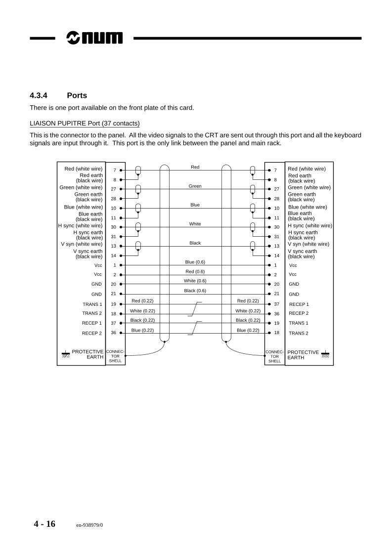
4.3.4 Ports
There is one port available on the front plate of this card.
LIAISON PUPITRE Port (37 contacts)
This is the connector to the panel. All the video signals to the CRT are sent out through this port and all the keyboardsignals are input through it. This port is the only link between the panel and main rack.
CONNEC-TOR
SHELL
1Vcc
2
20
Vcc
GND
GND
31
13
14
10
11
30
8
27
28
7
1 Vcc
2
20
Vcc
GND
GND
31
13
14
10
11
30
8
27
28
7
CONNEC-TOR
SHELL
Red
Green
Blue
White
Black
Blue (0.6)
Red (0.6)
White (0.6)
Black (0.6)21 21
19TRANS 1
18
37
TRANS 2
RECEP 1
RECEP 2
37 RECEP 1
36
19
RECEP 2
TRANS 1
TRANS 236 18
Red (0.22)
White (0.22)
Black (0.22)
Blue (0.22)
Red (0.22)
White (0.22)
Black (0.22)
Blue (0.22)
H sync earth(black wire)
V syn (white wire)V sync earth(black wire)
Blue (white wire)Blue earth
(black wire)H sync (white wire)
Red earth(black wire)
Green (white wire)Green earth(black wire)
Red (white wire)
H sync earth(black wire)V syn (white wire)V sync earth(black wire)
Blue (white wire)Blue earth(black wire)H sync (white wire)
Red earth(black wire)Green (white wire)Green earth(black wire)
Red (white wire)
PROTECTIVEEARTH
PROTECTIVEEARTH
en-938979/0 4 - 17
Processors
4
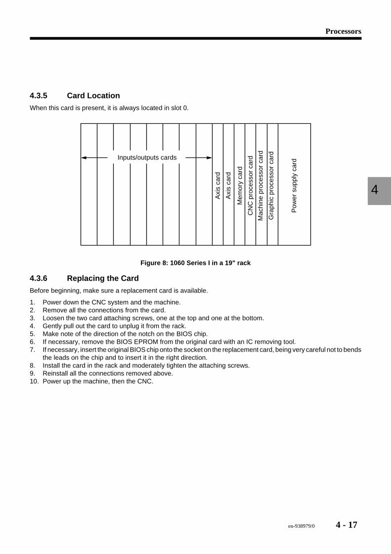
4.3.5 Card Location
When this card is present, it is always located in slot 0.
Mac
hine
pro
cess
or c
ard
Gra
phic
pro
cess
or c
ard
Pow
er s
uppl
y ca
rd
CN
C p
roce
ssor
car
d
Mem
ory
card
Axi
s ca
rd
Axi
s ca
rd
Inputs/outputs cards
Figure 8: 1060 Series I in a 19" rack
4.3.6 Replacing the Card
Before beginning, make sure a replacement card is available.
1. Power down the CNC system and the machine.2. Remove all the connections from the card.3. Loosen the two card attaching screws, one at the top and one at the bottom.4. Gently pull out the card to unplug it from the rack.5. Make note of the direction of the notch on the BIOS chip.6. If necessary, remove the BIOS EPROM from the original card with an IC removing tool.7. If necessary, insert the original BIOS chip onto the socket on the replacement card, being very careful not to bends
the leads on the chip and to insert it in the right direction.8. Install the card in the rack and moderately tighten the attaching screws.9. Reinstall all the connections removed above.10. Power up the machine, then the CNC.
4 - 18 en-938979/0
4.4 UCSII Monoprocessor
Halt
Def
UC SII
LIAISON
PUPITRE
COMM1
COMM2
E/S
ANALOG
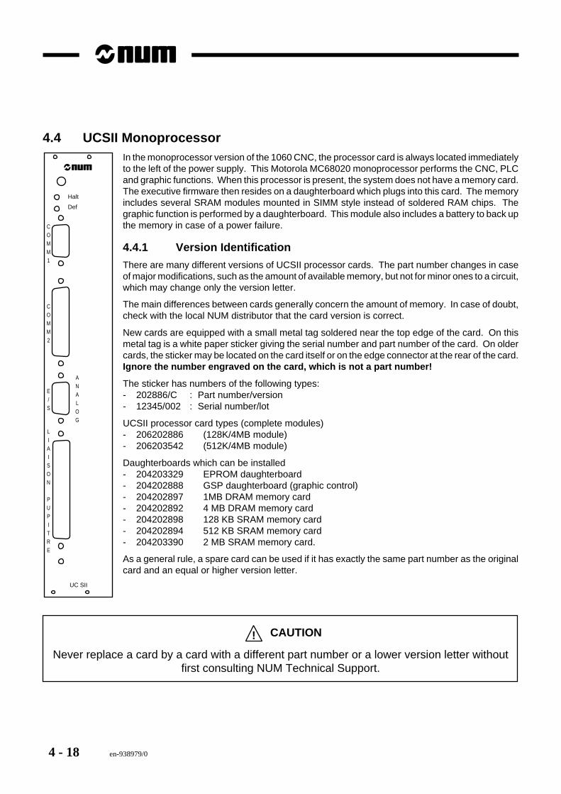
In the monoprocessor version of the 1060 CNC, the processor card is always located immediatelyto the left of the power supply. This Motorola MC68020 monoprocessor performs the CNC, PLCand graphic functions. When this processor is present, the system does not have a memory card.The executive firmware then resides on a daughterboard which plugs into this card. The memoryincludes several SRAM modules mounted in SIMM style instead of soldered RAM chips. Thegraphic function is performed by a daughterboard. This module also includes a battery to back upthe memory in case of a power failure.
4.4.1 Version Identification
There are many different versions of UCSII processor cards. The part number changes in caseof major modifications, such as the amount of available memory, but not for minor ones to a circuit,which may change only the version letter.
The main differences between cards generally concern the amount of memory. In case of doubt,check with the local NUM distributor that the card version is correct.
New cards are equipped with a small metal tag soldered near the top edge of the card. On thismetal tag is a white paper sticker giving the serial number and part number of the card. On oldercards, the sticker may be located on the card itself or on the edge connector at the rear of the card.Ignore the number engraved on the card, which is not a part number!
The sticker has numbers of the following types:- 202886/C : Part number/version- 12345/002 : Serial number/lot
UCSII processor card types (complete modules)- 206202886 (128K/4MB module)- 206203542 (512K/4MB module)
Daughterboards which can be installed- 204203329 EPROM daughterboard- 204202888 GSP daughterboard (graphic control)- 204202897 1MB DRAM memory card- 204202892 4 MB DRAM memory card- 204202898 128 KB SRAM memory card- 204202894 512 KB SRAM memory card- 204203390 2 MB SRAM memory card.
As a general rule, a spare card can be used if it has exactly the same part number as the originalcard and an equal or higher version letter.
! CAUTION
Never replace a card by a card with a different part number or a lower version letter withoutfirst consulting NUM Technical Support.
en-938979/0 4 - 19
Processors
4
4.4.2 LEDs
The front plate of this card includes two red LEDs, marked DEF and HALT. Under normal operating conditions, neitherLED is lit, except during start-up, when they may come on briefly.
DEF LED
If the DEF LED is lit steady, the processor card is no longer operating. It may be a hardware or a software failure, butthe most frequent cause is a problem with the software or memory. It is then necessary to reboot the system.
HALT LED
If the HALT LED is lit steady, the processor has stopped generally due to a fault on the card. However, the fault is notnecessarily on the card.
Replace the card and reboot the system. If the system hangs on reboot or stops later with the same fault, reinstall theoriginal card, which was not the cause of the failure, and look elsewhere for the cause.
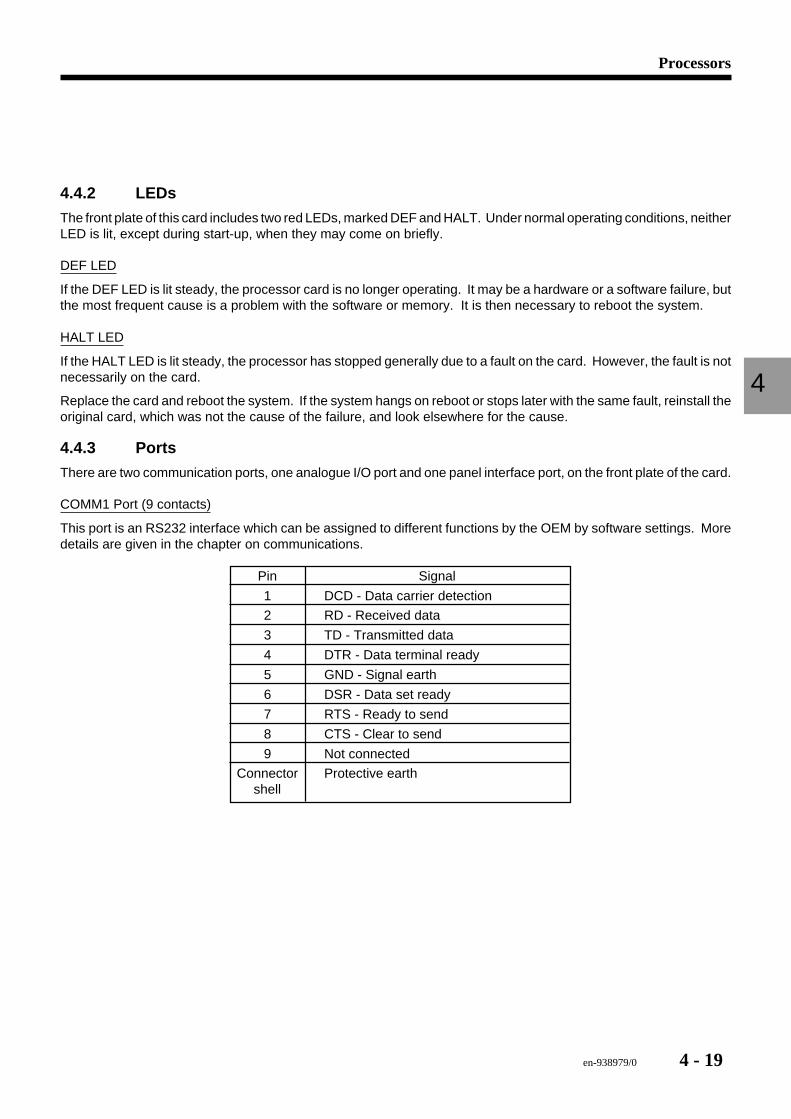
4.4.3 Ports
There are two communication ports, one analogue I/O port and one panel interface port, on the front plate of the card.
COMM1 Port (9 contacts)
This port is an RS232 interface which can be assigned to different functions by the OEM by software settings. Moredetails are given in the chapter on communications.
Pin Signal
1 DCD - Data carrier detection
2 RD - Received data
3 TD - Transmitted data
4 DTR - Data terminal ready
5 GND - Signal earth
6 DSR - Data set ready
7 RTS - Ready to send
8 CTS - Clear to send
9 Not connected
Connector Protective earthshell
4 - 20 en-938979/0
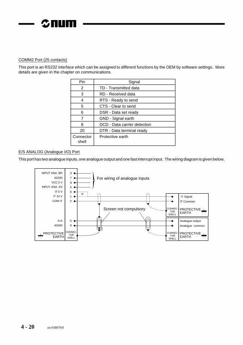
COMM2 Port (25 contacts)
This port is an RS232 interface which can be assigned to different functions by the OEM by software settings. Moredetails are given in the chapter on communications.
Pin Signal
2 TD - Transmitted data
3 RD - Received data
4 RTS - Ready to send
5 CTS - Clear to send
6 DSR - Data set ready
7 GND - Signal earth
8 DCD - Data carrier detection
20 DTR - Data terminal ready
Connector Protective earthshell
E/S ANALOG (Analogue I/O) Port
This port has two analogue inputs, one analogue output and one fast interrupt input. The wiring diagram is given below.
6
1
2
5
9
3
7
8
4
COM IT
S-A
AGND
IT 24 V
IT 5 V
INPUT ANA. BR
AGND
VCC 5 V
INPUT ANA. AV
or IT Signal
IT Common
Analogue output
Analogue common
Screen not compulsory
For wiring of analogue inputs
PROTECTIVEEARTH
PROTECTIVEEARTH
CONNEC-TOR
SHELL
PROTECTIVEEARTH
CONNEC-TOR
SHELL
CONNEC-TOR
SHELL
en-938979/0 4 - 21
Processors
4
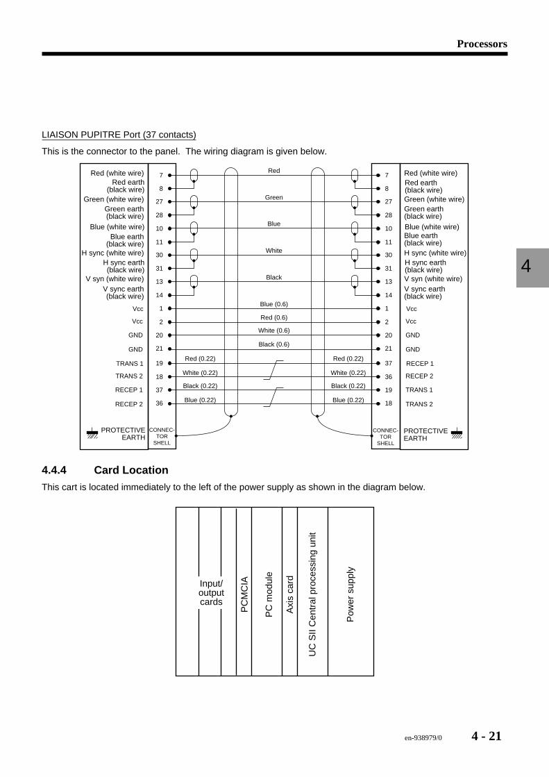
LIAISON PUPITRE Port (37 contacts)
This is the connector to the panel. The wiring diagram is given below.
CONNEC-TOR
SHELL
1Vcc
2
20
Vcc
GND
GND
31
13
14
10
11
30
8
27
28
7
1 Vcc
2
20
Vcc
GND
GND
31
13
14
10
11
30
8
27
28
7
CONNEC-TOR
SHELL
Red
Green
Blue
White
Black
Blue (0.6)
Red (0.6)
White (0.6)
Black (0.6)21 21
19TRANS 1
18
37
TRANS 2
RECEP 1
RECEP 2
37 RECEP 1
36
19
RECEP 2
TRANS 1
TRANS 236 18
Red (0.22)
White (0.22)
Black (0.22)
Blue (0.22)
Red (0.22)
White (0.22)
Black (0.22)
Blue (0.22)
H sync earth(black wire)
V syn (white wire)V sync earth(black wire)
Blue (white wire)Blue earth
(black wire)H sync (white wire)
Red earth(black wire)
Green (white wire)Green earth(black wire)
Red (white wire)
H sync earth(black wire)V syn (white wire)V sync earth(black wire)
Blue (white wire)Blue earth(black wire)H sync (white wire)
Red earth(black wire)Green (white wire)Green earth(black wire)
Red (white wire)
PROTECTIVEEARTH
PROTECTIVEEARTH
4.4.4 Card LocationThis cart is located immediately to the left of the power supply as shown in the diagram below.
UC
SII
Cen
tral
pro
cess
ing
unit
Pow
er s
uppl
y
Axi
s ca
rd
PC
mod
ule
PC
MC
IAInput/outputcards
4 - 22 en-938979/0
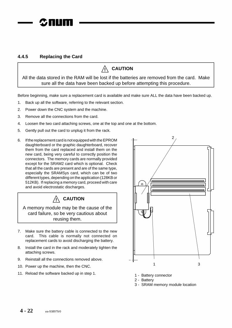
4.4.5 Replacing the Card
! CAUTION
All the data stored in the RAM will be lost if the batteries are removed from the card. Makesure all the data have been backed up before attempting this procedure.
Before beginning, make sure a replacement card is available and make sure ALL the data have been backed up.
1. Back up all the software, referring to the relevant section.
2. Power down the CNC system and the machine.
3. Remove all the connections from the card.
4. Loosen the two card attaching screws, one at the top and one at the bottom.
5. Gently pull out the card to unplug it from the rack.
1
2
3
1 - Battery connector2 - Battery3 - SRAM memory module location
6. If the replacement card is not equipped with the EPROMdaughterboard or the graphic daughterboard, recoverthem from the card replaced and install them on thenew card, being very careful to correctly position theconnectors. The memory cards are normally providedexcept for the SRAM2 card which is optional. Checkthat all the cards are present and are of the same type,especially the SRAMSys card, which can be of twodifferent types, depending on the application (128KB or512KB). If replacing a memory card, proceed with careand avoid electrostatic discharges.
! CAUTION
A memory module may be the cause of thecard failure, so be very cautious about
reusing them.
7. Make sure the battery cable is connected to the newcard. This cable is normally not connected onreplacement cards to avoid discharging the battery.
8. Install the card in the rack and moderately tighten theattaching screws.
9. Reinstall all the connections removed above.
10. Power up the machine, then the CNC.
11. Reload the software backed up in step 1.
en-938979/0 4 - 23
Processors
4
4.5 PCNC Processor
Déf.
COM1
COM2
LPT1
LIAISON
PUPITRE
Proc. PC
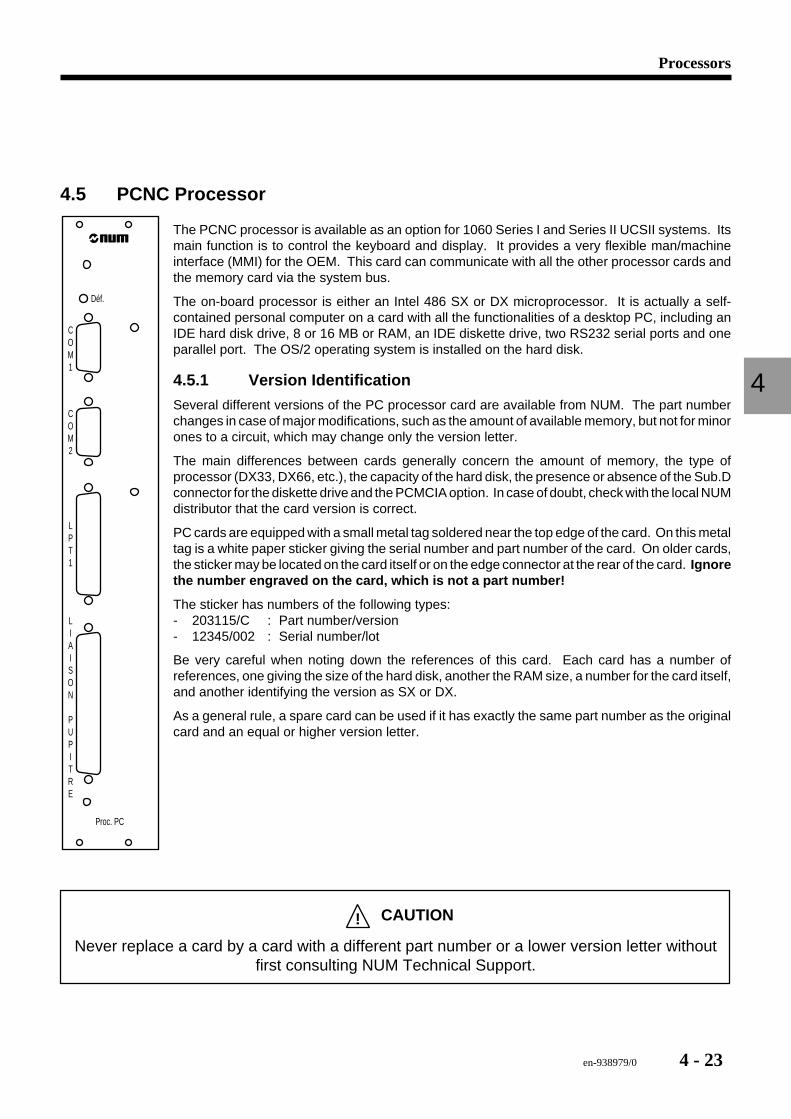
The PCNC processor is available as an option for 1060 Series I and Series II UCSII systems. Itsmain function is to control the keyboard and display. It provides a very flexible man/machineinterface (MMI) for the OEM. This card can communicate with all the other processor cards andthe memory card via the system bus.
The on-board processor is either an Intel 486 SX or DX microprocessor. It is actually a self-contained personal computer on a card with all the functionalities of a desktop PC, including anIDE hard disk drive, 8 or 16 MB or RAM, an IDE diskette drive, two RS232 serial ports and oneparallel port. The OS/2 operating system is installed on the hard disk.
4.5.1 Version Identification
Several different versions of the PC processor card are available from NUM. The part numberchanges in case of major modifications, such as the amount of available memory, but not for minorones to a circuit, which may change only the version letter.
The main differences between cards generally concern the amount of memory, the type ofprocessor (DX33, DX66, etc.), the capacity of the hard disk, the presence or absence of the Sub.Dconnector for the diskette drive and the PCMCIA option. In case of doubt, check with the local NUMdistributor that the card version is correct.
PC cards are equipped with a small metal tag soldered near the top edge of the card. On this metaltag is a white paper sticker giving the serial number and part number of the card. On older cards,the sticker may be located on the card itself or on the edge connector at the rear of the card. Ignorethe number engraved on the card, which is not a part number!
The sticker has numbers of the following types:- 203115/C : Part number/version- 12345/002 : Serial number/lot
Be very careful when noting down the references of this card. Each card has a number ofreferences, one giving the size of the hard disk, another the RAM size, a number for the card itself,and another identifying the version as SX or DX.
As a general rule, a spare card can be used if it has exactly the same part number as the originalcard and an equal or higher version letter.
! CAUTION
Never replace a card by a card with a different part number or a lower version letter withoutfirst consulting NUM Technical Support.
4 - 24 en-938979/0
4.5.2 LEDs
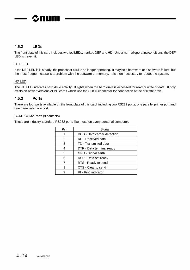
The front plate of this card includes two red LEDs, marked DEF and HD. Under normal operating conditions, the DEFLED is never lit.
DEF LED
If the DEF LED is lit steady, the processor card is no longer operating. It may be a hardware or a software failure, butthe most frequent cause is a problem with the software or memory. It is then necessary to reboot the system.
HD LED
The HD LED indicates hard drive activity. It lights when the hard drive is accessed for read or write of data. It onlyexists on newer versions of PC cards which use the Sub.D connector for connection of the diskette drive.
4.5.3 Ports
There are four ports available on the front plate of this card, including two RS232 ports, one parallel printer port andone panel interface port.
COM1/COM2 Ports (9 contacts)
These are industry-standard RS232 ports like those on every personal computer.
Pin Signal
1 DCD - Data carrier detection
2 RD - Received data
3 TD - Transmitted data
4 DTR - Data terminal ready
5 GND - Signal earth
6 DSR - Data set ready
7 RTS - Ready to send
8 CTS - Clear to send
9 RI - Ring indicator
en-938979/0 4 - 25
Processors
4
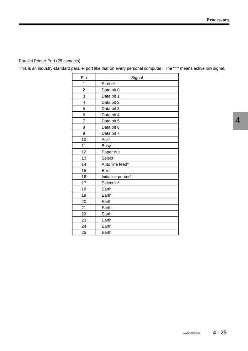
Parallel Printer Port (25 contacts)
This is an industry-standard parallel port like that on every personal computer. The "*" means active low signal.
Pin Signal
1 Strobe*
2 Data bit 0
3 Data bit 1
4 Data bit 2
5 Data bit 3
6 Data bit 4
7 Data bit 5
8 Data bit 6
9 Data bit 7
10 Ack*
11 Busy
12 Paper out
13 Select
14 Auto line feed*
15 Error
16 Initialise printer*
17 Select in*
18 Earth
19 Earth
20 Earth
21 Earth
22 Earth
23 Earth
24 Earth
25 Earth
4 - 26 en-938979/0
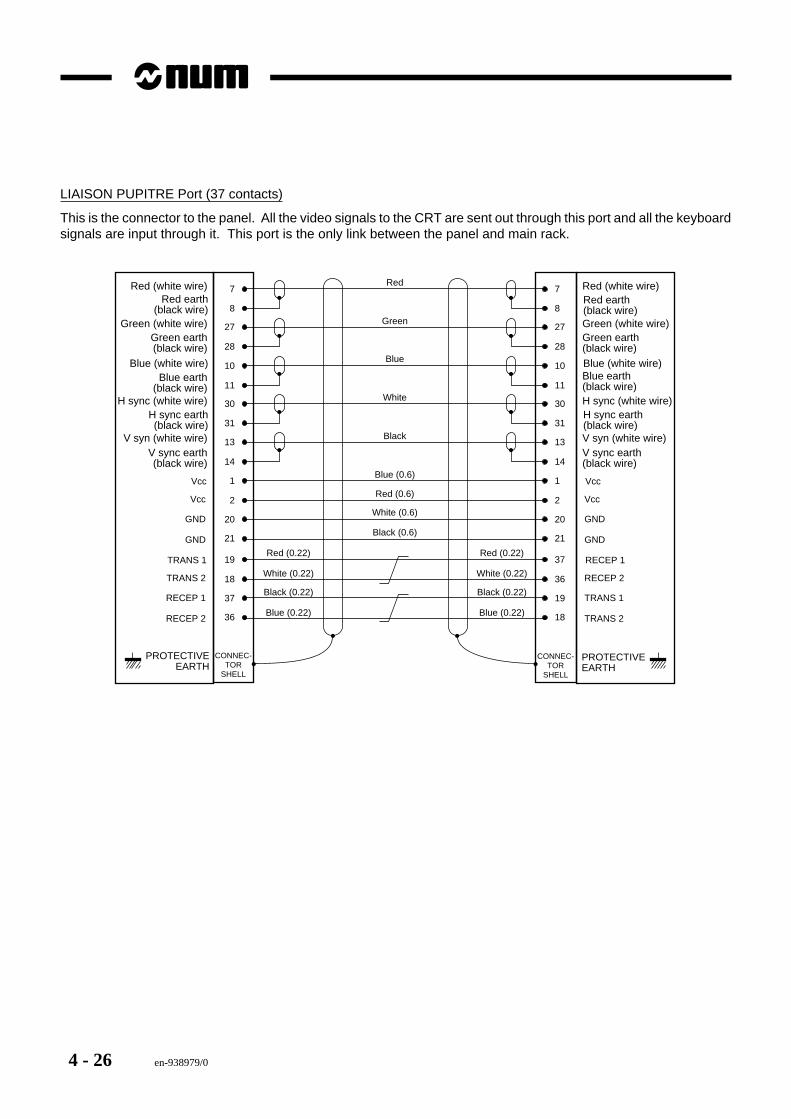
LIAISON PUPITRE Port (37 contacts)
This is the connector to the panel. All the video signals to the CRT are sent out through this port and all the keyboardsignals are input through it. This port is the only link between the panel and main rack.
CONNEC-TOR
SHELL
1Vcc
2
20
Vcc
GND
GND
31
13
14
10
11
30
8
27
28
7
1 Vcc
2
20
Vcc
GND
GND
31
13
14
10
11
30
8
27
28
7
CONNEC-TOR
SHELL
Red
Green
Blue
White
Black
Blue (0.6)
Red (0.6)
White (0.6)
Black (0.6)21 21
19TRANS 1
18
37
TRANS 2
RECEP 1
RECEP 2
37 RECEP 1
36
19
RECEP 2
TRANS 1
TRANS 236 18
Red (0.22)
White (0.22)
Black (0.22)
Blue (0.22)
Red (0.22)
White (0.22)
Black (0.22)
Blue (0.22)
H sync earth(black wire)
V syn (white wire)V sync earth(black wire)
Blue (white wire)Blue earth
(black wire)H sync (white wire)
Red earth(black wire)
Green (white wire)Green earth(black wire)
Red (white wire)
H sync earth(black wire)V syn (white wire)V sync earth(black wire)
Blue (white wire)Blue earth(black wire)H sync (white wire)
Red earth(black wire)Green (white wire)Green earth(black wire)
Red (white wire)
PROTECTIVEEARTH
PROTECTIVEEARTH
en-938979/0 4 - 27
Processors
4
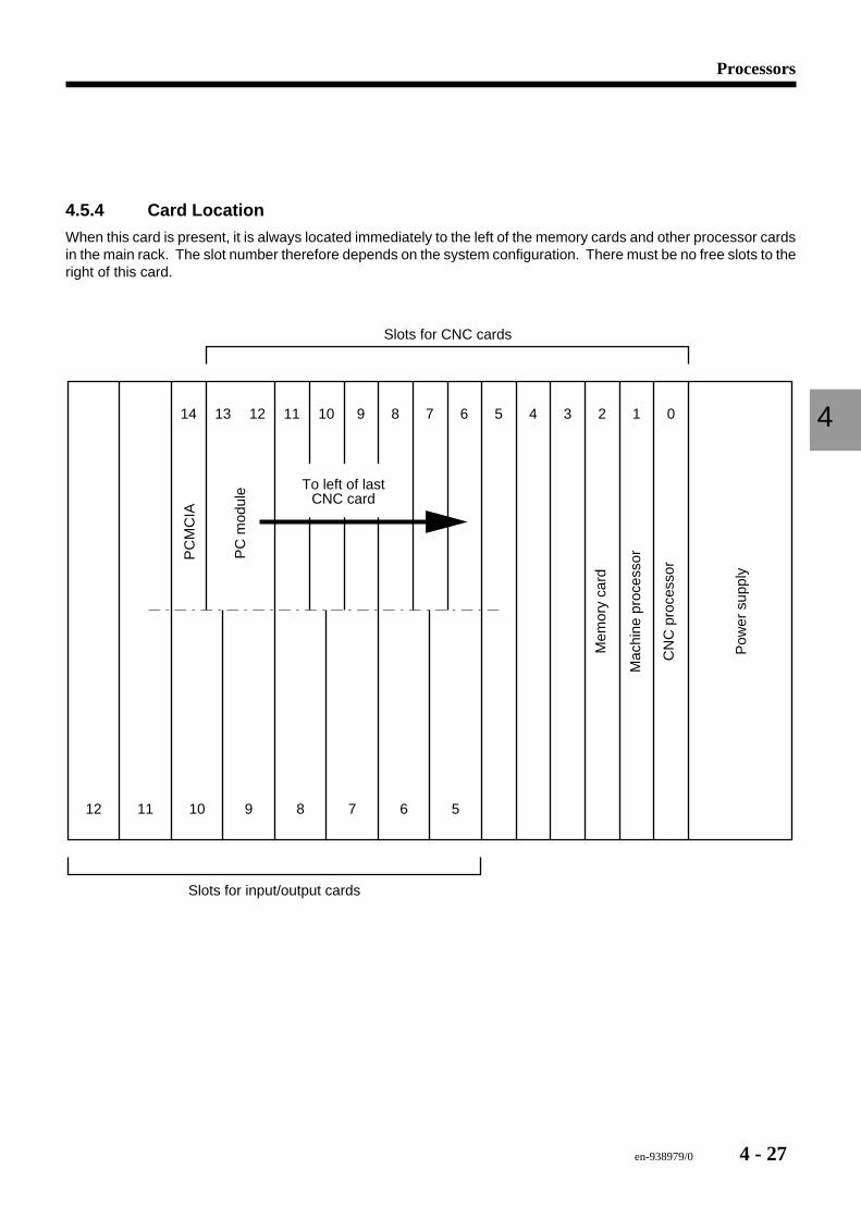
4.5.4 Card Location
When this card is present, it is always located immediately to the left of the memory cards and other processor cardsin the main rack. The slot number therefore depends on the system configuration. There must be no free slots to theright of this card.
12 11 10 8 7 6 5
11
9
121314 10 9 8 7 6 5 4 3 2 1 0
Slots for CNC cards
Slots for input/output cards
Mac
hine
pro
cess
or
CN
C p
roce
ssor
Pow
er s
uppl
y
Mem
ory
card
PC
mod
ule
PC
MC
IA
To left of lastCNC card
4 - 28 en-938979/0
4.5.5 Pre-replacement Diagnostics
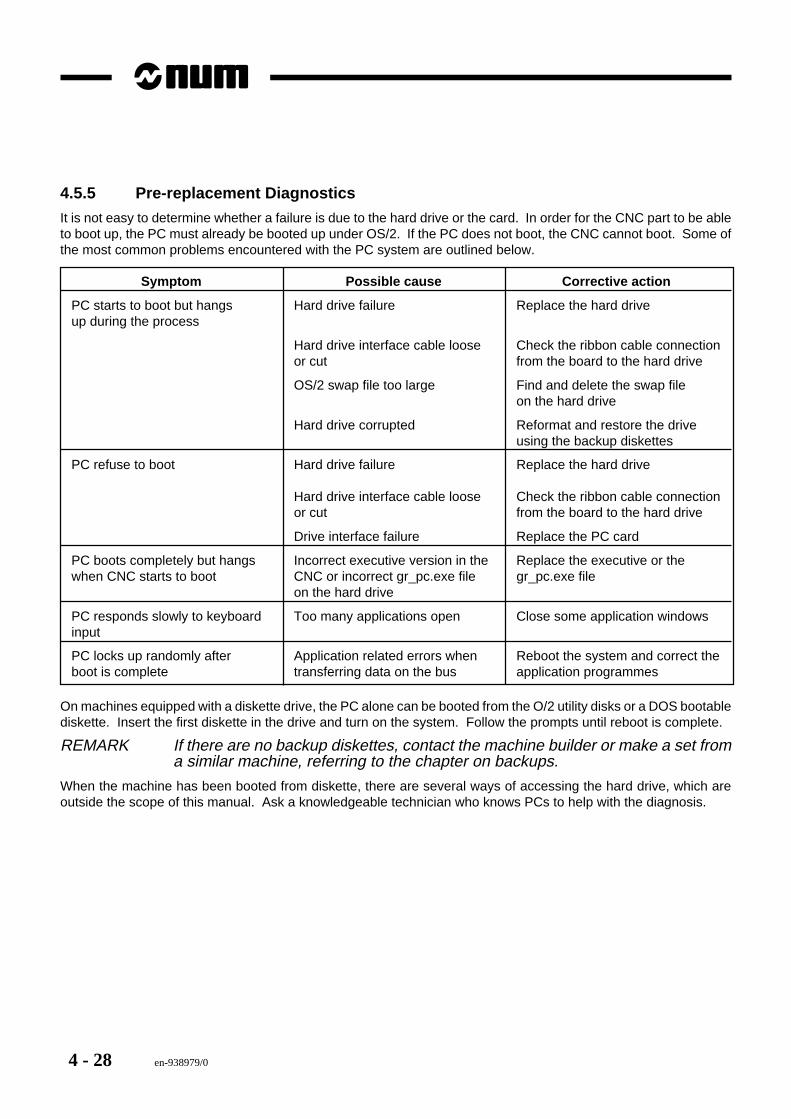
It is not easy to determine whether a failure is due to the hard drive or the card. In order for the CNC part to be ableto boot up, the PC must already be booted up under OS/2. If the PC does not boot, the CNC cannot boot. Some ofthe most common problems encountered with the PC system are outlined below.
Symptom Possible cause Corrective action
PC starts to boot but hangs Hard drive failure Replace the hard driveup during the process
Hard drive interface cable loose Check the ribbon cable connectionor cut from the board to the hard drive
OS/2 swap file too large Find and delete the swap fileon the hard drive
Hard drive corrupted Reformat and restore the driveusing the backup diskettes
PC refuse to boot Hard drive failure Replace the hard drive
Hard drive interface cable loose Check the ribbon cable connectionor cut from the board to the hard drive
Drive interface failure Replace the PC card
PC boots completely but hangs Incorrect executive version in the Replace the executive or thewhen CNC starts to boot CNC or incorrect gr_pc.exe file gr_pc.exe file
on the hard drive
PC responds slowly to keyboard Too many applications open Close some application windowsinput
PC locks up randomly after Application related errors when Reboot the system and correct theboot is complete transferring data on the bus application programmes
On machines equipped with a diskette drive, the PC alone can be booted from the O/2 utility disks or a DOS bootablediskette. Insert the first diskette in the drive and turn on the system. Follow the prompts until reboot is complete.
REMARK If there are no backup diskettes, contact the machine builder or make a set froma similar machine, referring to the chapter on backups.
When the machine has been booted from diskette, there are several ways of accessing the hard drive, which areoutside the scope of this manual. Ask a knowledgeable technician who knows PCs to help with the diagnosis.
en-938979/0 4 - 29
Processors
4
4.5.6 Replacing the Card Alone
Before beginning, make sure a replacement card is available and make sure all the software has been backed up.Refer to Chapter 13.
1. Power down the CNC system and the machine.2. Remove all the connections from the card.3. Loosen the two card attaching screws, one at the top and one at the bottom.4. Gently pull out the card to unplug it from the rack.
! CAUTION
There may be other cables connected to the card from inside the rack, so remove the cardvery carefully, without pulling hard.
5. If there are other cables inside the rack connected to the card, it is probably the diskette drive connection. Takecareful note of the orientation of the connector on the card before removing it.
6. Place the card on a static control surface and disconnect the hard drive’s ribbon cable from the card, not the drive.7. Remove the hard drive from the card by removing the screws which hold the rubber mounts on the card. Do not
disconnect the rubber mounts from the card unless access to the card screws is impossible.8. Mount the original hard drive on the new PC card by proceeding strictly in reverse order.9. Connect the hard drive ribbon cable to the card, making sure that the cable connector is firmly pushed onto the
pins (this is a common source of trouble).10. Reconnect the diskette drive cable coming from inside the rack if so equipped.11. Install the card in the rack and moderately tighten the attaching screws.12. Reinstall all the connections removed above.13. Power up the machine, then the CNC.14. It may be necessary to configure the CMOS RAM to match the hard drive with the new card. Refer to the section
on PC CMOS configuration for more information.
4.5.7 Card and Hard Drive Replacement Procedure
Before beginning, make sure a replacement card is available with a working hard drive.
! CAUTION
The new card may not have the application programmes which were installed on the harddrive by the OEM. They will then have to be reinstalled. Refer to the section on software
backup/restore procedures.
1. Power down the CNC system and the machine.2. Remove all the connections from the card.3. Loosen the two card attaching screws, one at the top and one at the bottom.4. Gently pull out the card to unplug it from the rack.
! CAUTION
There may be other cables connected to the card from inside the rack, so remove the cardvery carefully, without pulling hard.
4 - 30 en-938979/0
5. If there are other cables inside the rack connected to the card, it is probably the diskette drive connection. Takecareful note of the orientation of the connector on the card before removing it.
6. Reconnect the diskette drive cable coming from inside the rack if so equipped.7. Install the card in the rack and moderately tighten the attaching screws.8. Reinstall all the connections removed above.9. Power up the machine, then the CNC.10. It may be necessary to configure the CMOS RAM to match the hard drive with the new card. Refer to the section
on PC CMOS configuration for more information.
4.5.8 CMOS RAM Configuration AccessThe CMOS RAM is configured in the same way as on any personal computer. Only the command to access the utilityis different.
! CAUTION
Changing the CMOS configuration data could result in loss of functionality of the hard drive,pointing devices, diskette drives, memory allocation, etc. Only trained technicians familiar
with PC configurations should attempt these changes.
To access the CMOS configuration routine, depress the CTRL+ALT+S keys simultaneously while the PC is bootingup from a power off state. Depress these keys at the end of the memory test and hold them depressed until the CMOSsetup page appears.
The CMOS configuration utility is used to specify the type of hard drive, diskette drive, CRT, and keyboard and to setthe date and time for the PC card. However, the only settings which should ever be adjusted are the hard drive settingsand the time/date settings if required. In particular, the diskette drive should never be enabled from here. It is controlledvia a software driver loaded in the config.sys file.
Since there are many types of hard drives currently available on the market, the settings for each drive are toonumerous to list herein. To find out the settings required for a given hard disk, either call NUM technical support orthe hard disk manufacturer. It is important to note that the CMOS RAM configuration does not allow custom drivesettings, but only a choice among predefined values on a list for each parameter. This means that it may not be possibleto exactly configure a given hard drive, if it does not match the available values.
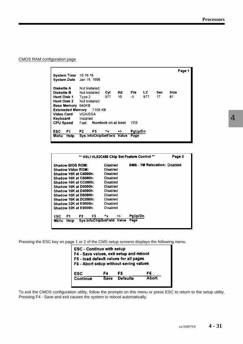
A typical CMOS RAM setup screen is illustrated below. For instance, the hard disk size is set to 81 MB. It also containsother parameters such as time, date, memory size, diskette drives (none selected, which is correct), hard drives, videomode, keyboard, etc.
Page 2 shows the shadow RAMs, which are usually all disabled.
en-938979/0 4 - 31
Processors
4
CMOS RAM configuration page
Pressing the ESC key on page 1 or 2 of the CMS setup screens displays the following menu.
To exit the CMOS configuration utility, follow the prompts on this menu or press ESC to return to the setup utility.Pressing F4 - Save and exit causes the system to reboot automatically.
4 - 32 en-938979/0
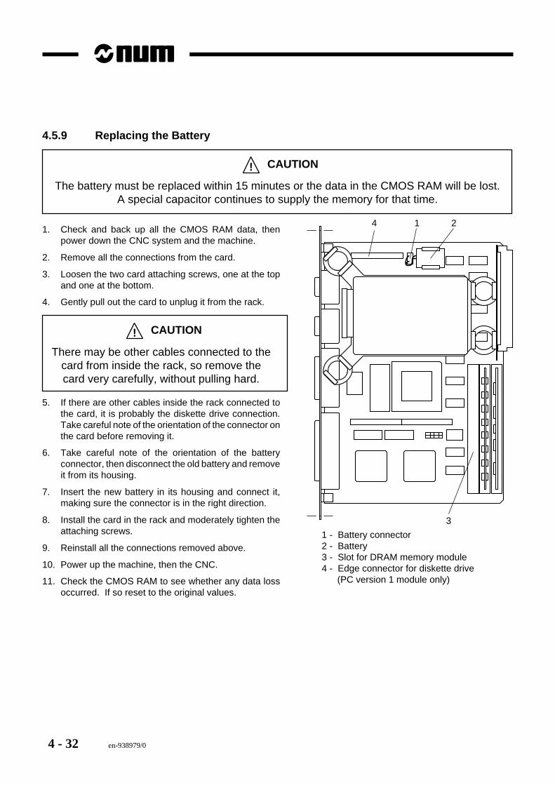
4.5.9 Replacing the Battery
! CAUTION
The battery must be replaced within 15 minutes or the data in the CMOS RAM will be lost.A special capacitor continues to supply the memory for that time.
2
3
14
1 - Battery connector2 - Battery3 - Slot for DRAM memory module4 - Edge connector for diskette drive (PC version 1 module only)
1. Check and back up all the CMOS RAM data, thenpower down the CNC system and the machine.
2. Remove all the connections from the card.
3. Loosen the two card attaching screws, one at the topand one at the bottom.
4. Gently pull out the card to unplug it from the rack.
! CAUTION
There may be other cables connected to thecard from inside the rack, so remove thecard very carefully, without pulling hard.
5. If there are other cables inside the rack connected tothe card, it is probably the diskette drive connection.Take careful note of the orientation of the connector onthe card before removing it.
6. Take careful note of the orientation of the batteryconnector, then disconnect the old battery and removeit from its housing.
7. Insert the new battery in its housing and connect it,making sure the connector is in the right direction.
8. Install the card in the rack and moderately tighten theattaching screws.
9. Reinstall all the connections removed above.
10. Power up the machine, then the CNC.
11. Check the CMOS RAM to see whether any data lossoccurred. If so reset to the original values.
en-938979/0 4 - 33
Processors
4
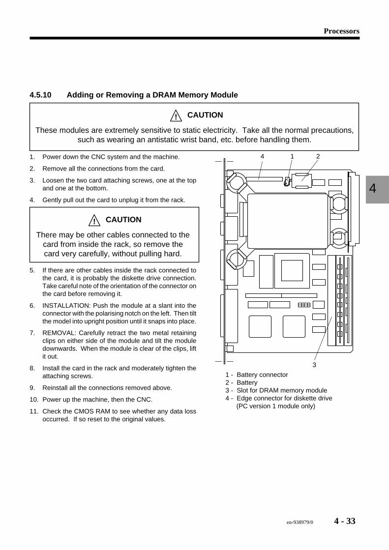
4.5.10 Adding or Removing a DRAM Memory Module
! CAUTION
These modules are extremely sensitive to static electricity. Take all the normal precautions,such as wearing an antistatic wrist band, etc. before handling them.
2
3
14
1 - Battery connector2 - Battery3 - Slot for DRAM memory module4 - Edge connector for diskette drive (PC version 1 module only)
1. Power down the CNC system and the machine.
2. Remove all the connections from the card.
3. Loosen the two card attaching screws, one at the topand one at the bottom.
4. Gently pull out the card to unplug it from the rack.
! CAUTION
There may be other cables connected to thecard from inside the rack, so remove thecard very carefully, without pulling hard.
5. If there are other cables inside the rack connected tothe card, it is probably the diskette drive connection.Take careful note of the orientation of the connector onthe card before removing it.
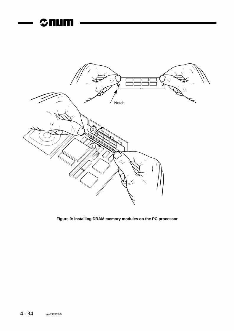
6. INSTALLATION: Push the module at a slant into theconnector with the polarising notch on the left. Then tiltthe model into upright position until it snaps into place.
7. REMOVAL: Carefully retract the two metal retainingclips on either side of the module and tilt the moduledownwards. When the module is clear of the clips, liftit out.
8. Install the card in the rack and moderately tighten theattaching screws.
9. Reinstall all the connections removed above.
10. Power up the machine, then the CNC.
11. Check the CMOS RAM to see whether any data lossoccurred. If so reset to the original values.
4 - 34 en-938979/0
Notch
2
1
Figure 9: Installing DRAM memory modules on the PC processor
en-938979/0 4 - 35
Processors
4
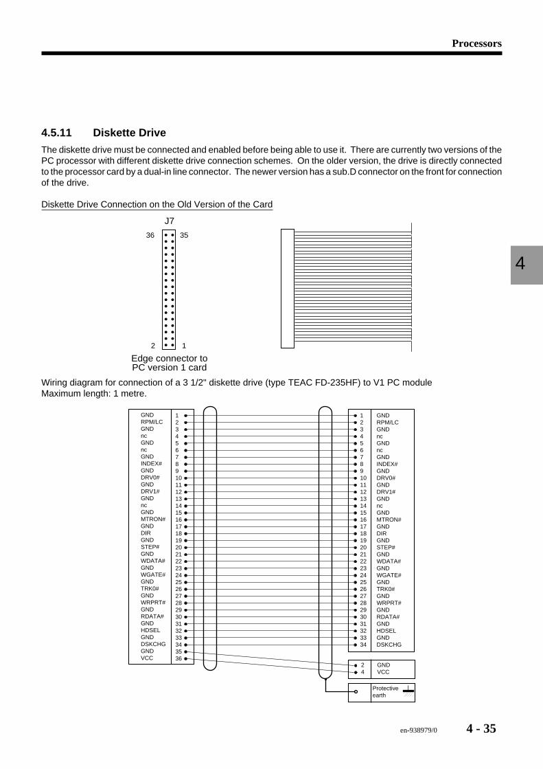
4.5.11 Diskette Drive
The diskette drive must be connected and enabled before being able to use it. There are currently two versions of thePC processor with different diskette drive connection schemes. On the older version, the drive is directly connectedto the processor card by a dual-in line connector. The newer version has a sub.D connector on the front for connectionof the drive.
Diskette Drive Connection on the Old Version of the Card
J7
2 1
3536
Edge connector toPC version 1 card
Wiring diagram for connection of a 3 1/2" diskette drive (type TEAC FD-235HF) to V1 PC moduleMaximum length: 1 metre.
GNDRPM/LCGNDncGNDncGNDINDEX#GNDDRV0#GNDDRV1#GNDncGNDMTRON#GNDDIRGNDSTEP#GNDWDATA#GNDWGATE#GNDTRK0#GNDWRPRT#GNDRDATA#GNDHDSELGNDDSKCHGGNDVCC
12345678910111213141516171819202122232425262728293031323334
GNDRPM/LCGNDncGNDncGNDINDEX#GNDDRV0#GNDDRV1#GNDncGNDMTRON#GNDDIRGNDSTEP#GNDWDATA#GNDWGATE#GNDTRK0#GNDWRPRT#GNDRDATA#GNDHDSELGNDDSKCHG
24
GNDVCC
123456789101112131415161718192021222324252627282930313233343536
Protectiveearth
4 - 36 en-938979/0
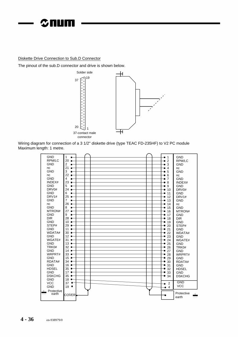
Diskette Drive Connection to Sub.D Connector
The pinout of the sub.D connector and drive is shown below.
Solder side
37-contact maleconnector
1
1937
20
Wiring diagram for connection of a 3 1/2" diskette drive (type TEAC FD-235HF) to V2 PC moduleMaximum length: 1 metre.
12022132242352462572682792810291130123113321433153416351735183719
GNDRPM/LCGNDncGNDncGNDINDEX#GNDDRV0#GNDDRV1#GNDncGNDMTRON#GNDDIRGNDSTEP#GNDWDATA#GNDWGATE#GNDTRK0#GNDWRPRT#GNDRDATA#GNDHDSELGNDDSKCHGGNDVCCGND
12345678910111213141516171819202122232425262728293031323334
GNDRPM/LCGNDncGNDncGNDINDEX#GNDDRV0#GNDDRV1#GNDncGNDMTRON#GNDDIRGNDSTEP#GNDWDATA#GNDWGATE#GNDTRK0#GNDWRPRT#GNDRDATA#GNDHDSELGNDDSKCHG
24
GNDVCC
Protectiveearth
COVERProtective
earth
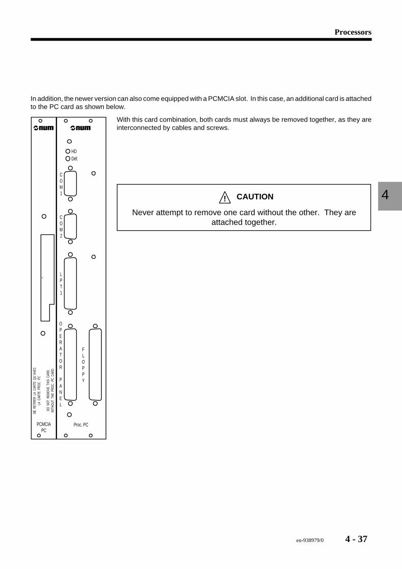
en-938979/0 4 - 37
Processors
4
In addition, the newer version can also come equipped with a PCMCIA slot. In this case, an additional card is attachedto the PC card as shown below.
PCMCIAPC
NE R
ETIR
ER L
A C
ARTE
QU'
AVE
CLA
CAR
TE P
ROC.
PC
DO N
OT R
EMOV
E T
HIS
CAR
DW
ITHO
UT T
HE P
ROC.
PC
CAR
D
Déf.HD
COM1
COM2
LPT1
FLOPPY
OPERATOR
PANEL
Proc. PC
With this card combination, both cards must always be removed together, as they areinterconnected by cables and screws.
! CAUTION
Never attempt to remove one card without the other. They areattached together.
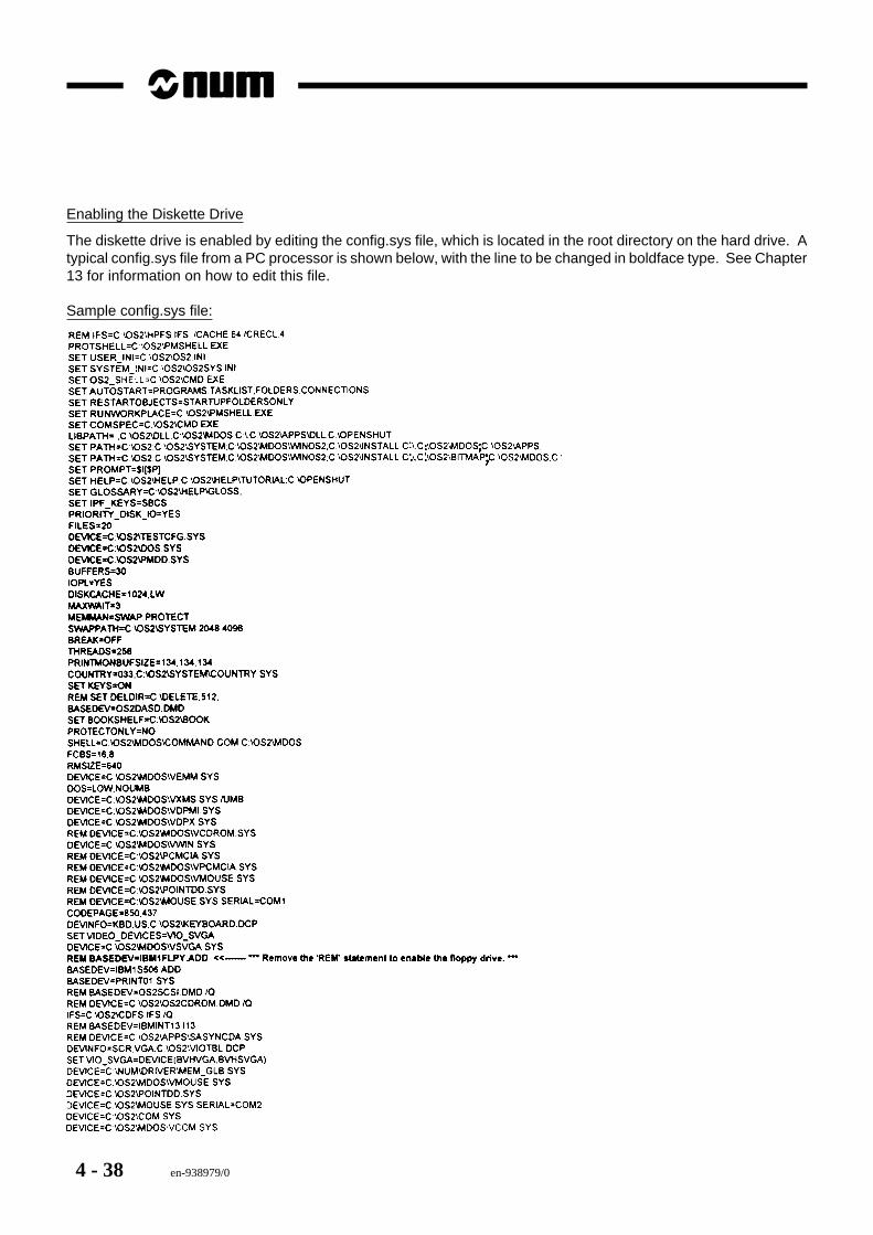
4 - 38 en-938979/0
Enabling the Diskette Drive
The diskette drive is enabled by editing the config.sys file, which is located in the root directory on the hard drive. Atypical config.sys file from a PC processor is shown below, with the line to be changed in boldface type. See Chapter13 for information on how to edit this file.
Sample config.sys file:
Processeurs
4
en-938979/0 4 - 39
4.6 1020/1040 Motherboard
This board is functionally very similar to the UCSII board. The difference resides in the absence of a rack. 1020systems consist of a motherboard containing the customisation parameters usually stored in the rack, to which areconnected axis cards and I/O cards. This Motorola MC68020 monoprocessor performs the CNC, PLC and graphicfunctions. The executive firmware resides on a daughterboard which plugs into this card. The memory includesseveral SRAM modules mounted in SIMM style instead of soldered RAM chips. The graphic function is performedby a daughterboard. This module also includes a battery to back up the memory in case of a power failure.
4.6.1 Version IdentificationThere are several different versions of 1020/1040 cards. The part number changes in case of major modifications,such as the amount of available memory, but not for minor ones to a circuit, which may change only the version letter.
The main differences between cards generally concern the amount of memory. In case of doubt, check with the localNUM distributor that the card version is correct.
New cards are equipped with a small metal tag soldered near the top edge of the card. On this metal tag is a whitepaper sticker giving the serial number and part number of the card. On older cards, the sticker may be located on thecard itself or on the edge connector at the rear of the card. Ignore the number engraved on the card, which is nota part number!
The sticker has numbers of the following types:- 203310/C : Part number/version- 12345/002 : Serial number/lot
1020/1040 processor card types (complete modules)- 204203310
Daughterboards which can be installed- 204203329 EPROM daughterboard- 204202888 GSP daughterboard (graphic control)- 204202897 1MB DRAM memory card- 204202892 4 MB DRAM memory card- 204202898 128 KB SRAM memory card- 204202894 512 KB SRAM memory card- 204203390 2 MB SRAM memory card.
As a general rule, a spare card can be used if it has exactly the same part number as the original card and an equalor higher version letter.
! CAUTION
Never replace a card by a card with a different part number or a lower version letter withoutfirst consulting NUM Technical Support.
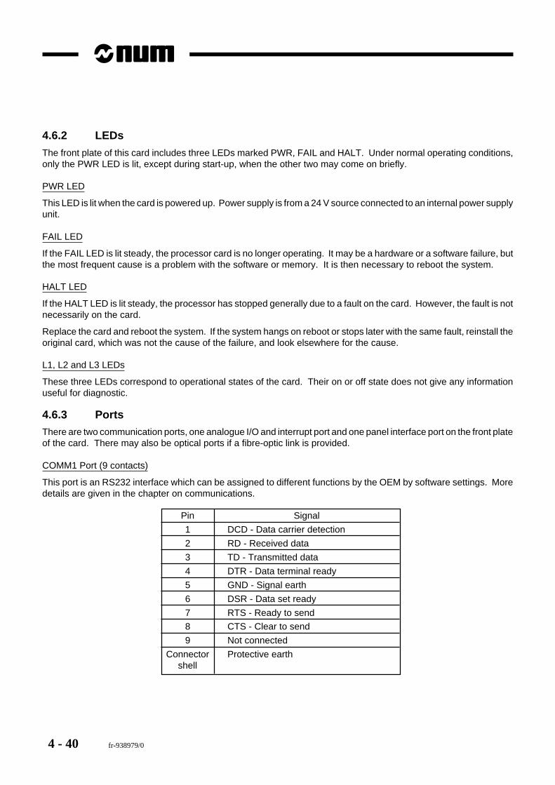
4 - 40 fr-938979/0
4.6.2 LEDs
The front plate of this card includes three LEDs marked PWR, FAIL and HALT. Under normal operating conditions,only the PWR LED is lit, except during start-up, when the other two may come on briefly.
PWR LED
This LED is lit when the card is powered up. Power supply is from a 24 V source connected to an internal power supplyunit.
FAIL LED
If the FAIL LED is lit steady, the processor card is no longer operating. It may be a hardware or a software failure, butthe most frequent cause is a problem with the software or memory. It is then necessary to reboot the system.
HALT LED
If the HALT LED is lit steady, the processor has stopped generally due to a fault on the card. However, the fault is notnecessarily on the card.
Replace the card and reboot the system. If the system hangs on reboot or stops later with the same fault, reinstall theoriginal card, which was not the cause of the failure, and look elsewhere for the cause.
L1, L2 and L3 LEDs
These three LEDs correspond to operational states of the card. Their on or off state does not give any informationuseful for diagnostic.
4.6.3 PortsThere are two communication ports, one analogue I/O and interrupt port and one panel interface port on the front plateof the card. There may also be optical ports if a fibre-optic link is provided.
COMM1 Port (9 contacts)
This port is an RS232 interface which can be assigned to different functions by the OEM by software settings. Moredetails are given in the chapter on communications.
Pin Signal
1 DCD - Data carrier detection
2 RD - Received data
3 TD - Transmitted data
4 DTR - Data terminal ready
5 GND - Signal earth
6 DSR - Data set ready
7 RTS - Ready to send
8 CTS - Clear to send
9 Not connected
Connector Protective earthshell
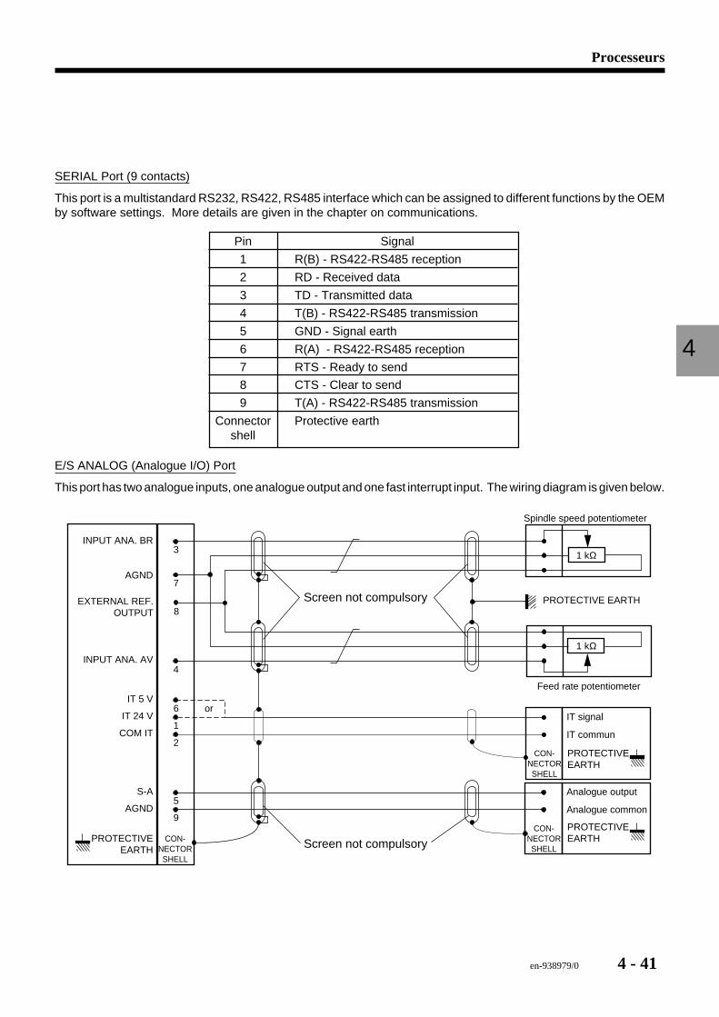
Processeurs
4
en-938979/0 4 - 41
SERIAL Port (9 contacts)
This port is a multistandard RS232, RS422, RS485 interface which can be assigned to different functions by the OEMby software settings. More details are given in the chapter on communications.
Pin Signal
1 R(B) - RS422-RS485 reception
2 RD - Received data
3 TD - Transmitted data
4 T(B) - RS422-RS485 transmission
5 GND - Signal earth
6 R(A) - RS422-RS485 reception
7 RTS - Ready to send
8 CTS - Clear to send
9 T(A) - RS422-RS485 transmission
Connector Protective earthshell
E/S ANALOG (Analogue I/O) Port
This port has two analogue inputs, one analogue output and one fast interrupt input. The wiring diagram is given below.
6
1
2
5
9
3
7
8
4
COM IT
S-A
AGND
IT 24 V
IT 5 V
INPUT ANA. BR
AGND
EXTERNAL REF.OUTPUT
PROTECTIVEEARTH
INPUT ANA. AV
orIT signal
IT commun
PROTECTIVEEARTH
Analogue output
Analogue common
CON-NECTORSHELL
PROTECTIVEEARTHCON-
NECTORSHELL
CON-NECTORSHELL
Screen not compulsory
1 kΩ
1 kΩ
Spindle speed potentiometer
Feed rate potentiometer
PROTECTIVE EARTHScreen not compulsory
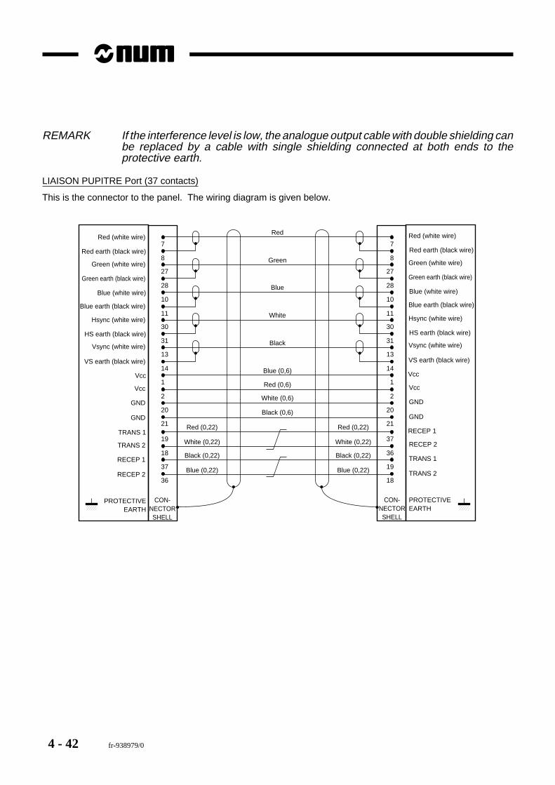
4 - 42 fr-938979/0
REMARK If the interference level is low, the analogue output cable with double shielding canbe replaced by a cable with single shielding connected at both ends to theprotective earth.
LIAISON PUPITRE Port (37 contacts)
This is the connector to the panel. The wiring diagram is given below.
CON-NECTORSHELL
PROTECTIVEEARTH
1Vcc
2
20
Vcc
GND
GND
31HS earth (black wire)
13
14
Vsync (white wire)
VS earth (black wire)
10Blue (white wire)
11
30
Blue earth (black wire)
Hsync (white wire)
8Red earth (black wire)
27
28
Green (white wire)
Green earth (black wire)
7Red (white wire)
1Vcc
2
20
Vcc
GND
GND
31
13
14
10
11
30
8
27
28
7
CON-NECTORSHELL
PROTECTIVEEARTH
Red
Green
Blue
White
Black
Blue (0,6)
Red (0,6)
White (0,6)
Black (0,6)
21 21
19TRANS 1
18
37
TRANS 2
RECEP 1
RECEP 2
37RECEP 1
36
19
RECEP 2
TRANS 1
TRANS 236 18
Red (0,22)
White (0,22)
Black (0,22)
Blue (0,22)
Red (0,22)
White (0,22)
Black (0,22)
Blue (0,22)
HS earth (black wire)
Vsync (white wire)
VS earth (black wire)
Blue (white wire)
Blue earth (black wire)
Hsync (white wire)
Red earth (black wire)
Green (white wire)
Green earth (black wire)
Red (white wire)

Processeurs
4
en-938979/0 4 - 43
4.6.4 Characteristics
Halt
Def
UC SII
LIAISON
PUPITRE
COMM1
COMM2
E/S
ANALOG
Power consumption 11 W maximumLocation CNC card slots 0 and 1
Serial Lines2 RS232 serial linesMaximum input voltage ± 30 VV
0L typical - 9 V
V0H
typical + 9 VExtreme loads 2000 pF, 5 kΩ (approximately 10 m of cable)Data rate 9600, 19200 or 38400 bauds
Analogue InputsThe inputs can be dedicated to connection of resistive potentiometersTypical potentiometer rating 1 kΩResolution 0.4 percent full scale value
Analogue OutputOutput voltage - 10 / + 10 VMinimum load 2 kΩMaximum error 20 mV (offset + accuracy)Output amplifier AD712 (Analog Device)
External InterruptMaximum current rating 20 mAMinimum current required 10 mA5 V input Logic "0" between 0 and 1 V
Logic "1" between 3.5 and 5.5 V24 V input Logic "0" between 0 and 4.7 V
Logic "1" between 18 and 27 VIT duration Programmable: T1 = 0,5/250/500/2220/4440 µsMasking between 2 ITs Programmable: T2 = 1/500/1000/4000/8000 µs
Interrupt timing diagram:
t ≥ T1 t ≥ T2Rising edge active
Falling edge activeIT masking
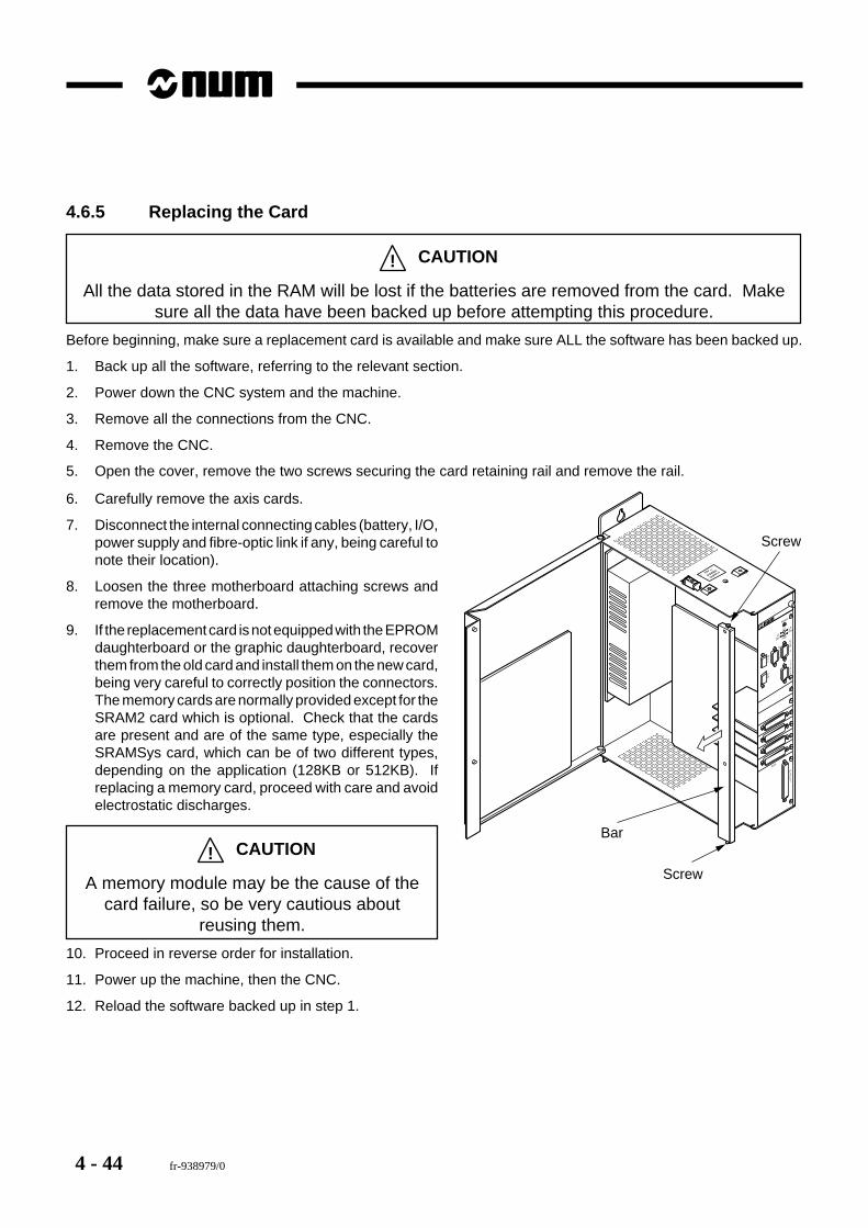
4 - 44 fr-938979/0
4.6.5 Replacing the Card
! CAUTION
All the data stored in the RAM will be lost if the batteries are removed from the card. Makesure all the data have been backed up before attempting this procedure.
Before beginning, make sure a replacement card is available and make sure ALL the software has been backed up.
1. Back up all the software, referring to the relevant section.
2. Power down the CNC system and the machine.
3. Remove all the connections from the CNC.
4. Remove the CNC.
5. Open the cover, remove the two screws securing the card retaining rail and remove the rail.
It/Ana
Com 1
Serial
Rec
Em
L1
Def
L3PwrL2
Fail
Reset
Axis
Panel
24V DC
POWER
SUPPLY+
-
Bar
Screw
Screw
6. Carefully remove the axis cards.
7. Disconnect the internal connecting cables (battery, I/O,power supply and fibre-optic link if any, being careful tonote their location).
8. Loosen the three motherboard attaching screws andremove the motherboard.
9. If the replacement card is not equipped with the EPROMdaughterboard or the graphic daughterboard, recoverthem from the old card and install them on the new card,being very careful to correctly position the connectors.The memory cards are normally provided except for theSRAM2 card which is optional. Check that the cardsare present and are of the same type, especially theSRAMSys card, which can be of two different types,depending on the application (128KB or 512KB). Ifreplacing a memory card, proceed with care and avoidelectrostatic discharges.
! CAUTION
A memory module may be the cause of thecard failure, so be very cautious about
reusing them.
10. Proceed in reverse order for installation.
11. Power up the machine, then the CNC.
12. Reload the software backed up in step 1.
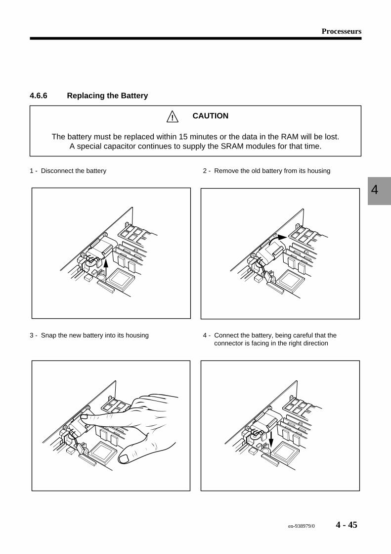
Processeurs
4
en-938979/0 4 - 45
4.6.6 Replacing the Battery
! CAUTION
The battery must be replaced within 15 minutes or the data in the RAM will be lost.A special capacitor continues to supply the SRAM modules for that time.
1 - Disconnect the battery 2 - Remove the old battery from its housing
3 - Snap the new battery into its housing 4 - Connect the battery, being careful that theconnector is facing in the right direction
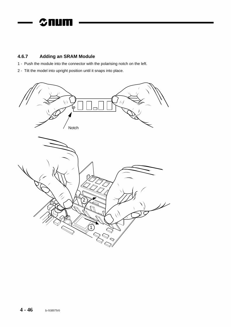
4 - 46 fr-938979/0
4.6.7 Adding an SRAM Module
1 - Push the module into the connector with the polarising notch on the left.
2 - Tilt the model into upright position until it snaps into place.
2
1
Notch
en-938979/0 5 - 1
Memory
5
5 Memory
5.1 Memory Card 5 - 35.1.1 Executive Firmware 5 - 35.1.2 Batteries 5 - 45.1.3 Battery Jumpers 5 - 45.1.4 Replacing the Card 5 - 5

5 - 2 en-938979/0
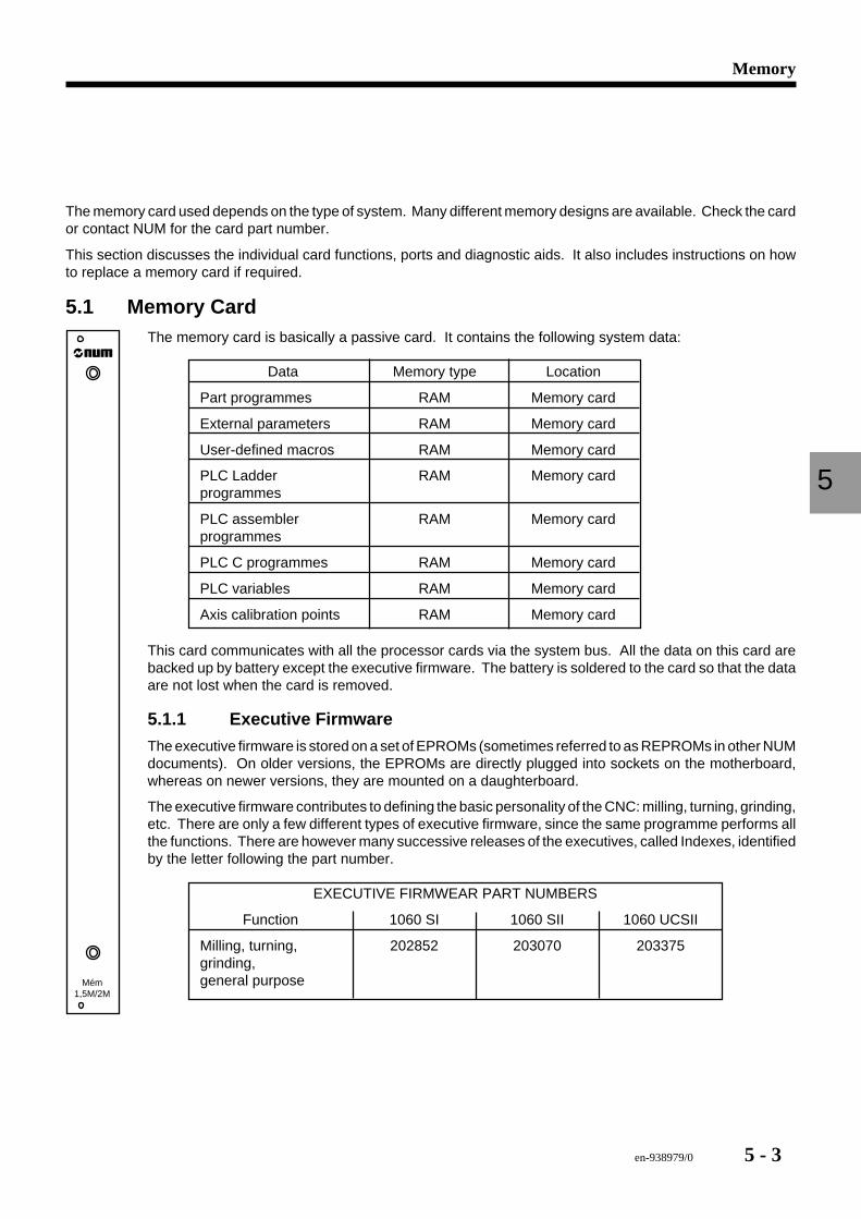
en-938979/0 5 - 3
Memory
5
The memory card used depends on the type of system. Many different memory designs are available. Check the cardor contact NUM for the card part number.
This section discusses the individual card functions, ports and diagnostic aids. It also includes instructions on howto replace a memory card if required.
5.1 Memory Card
Mém1,5M/2M
The memory card is basically a passive card. It contains the following system data:
Data Memory type Location
Part programmes RAM Memory card
External parameters RAM Memory card
User-defined macros RAM Memory card
PLC Ladder RAM Memory cardprogrammes
PLC assembler RAM Memory cardprogrammes
PLC C programmes RAM Memory card
PLC variables RAM Memory card
Axis calibration points RAM Memory card
This card communicates with all the processor cards via the system bus. All the data on this card arebacked up by battery except the executive firmware. The battery is soldered to the card so that the dataare not lost when the card is removed.
5.1.1 Executive Firmware
The executive firmware is stored on a set of EPROMs (sometimes referred to as REPROMs in other NUMdocuments). On older versions, the EPROMs are directly plugged into sockets on the motherboard,whereas on newer versions, they are mounted on a daughterboard.
The executive firmware contributes to defining the basic personality of the CNC: milling, turning, grinding,etc. There are only a few different types of executive firmware, since the same programme performs allthe functions. There are however many successive releases of the executives, called Indexes, identifiedby the letter following the part number.
EXECUTIVE FIRMWEAR PART NUMBERS
Function 1060 SI 1060 SII 1060 UCSII
Milling, turning, 202852 203070 203375grinding,general purpose
5 - 4 en-938979/0
The EPROM sockets are numbered U1, U2, U3, U4 or U1, V1, W1, etc. These numbers are etched on the card. Alwaysnote down the socket number on a chip before removing it to be able to reinstall it in the same socket. This is veryimportant to prevent problems.
If the memory card is equipped with a daughterboard. The daughterboard may easily be removed if needed. Be verycareful not to bend the leads when reinstalling it.
5.1.2 Batteries
! CAUTION
All the data stored in the RAM will be lost if the batteries are removed from the card. Makesure all the data have been backed up before attempting this procedure.
The batteries are soldered in the lower right-hand corner of the memory card, near the bus connector. These batteriesare under a constant charge whenever the rack is on. When the rack is turned off, the batteries supply the RAM chipsto preserve the data they contain.
The batteries can be replaced, but only by a skilled technician with suitable tools. Replacement batteries can beobtained from NUM technical support.
5.1.3 Battery Jumpers
! CAUTION
Removing these jumpers causes a total loss of all the data contained in the RAM.
The two small jumpers located near the batteries control charging and discharging. If the jumpers are removed, thebatteries are not kept charged and will not be able to maintain the RAMs supplied.
One jumper controls charging and one controls the RAM socket. Their orientation is critical. The jumpers must beinstalled parallel to the bottom of the memory card. NEVER INSTALL THE JUMPERS PERPENDICULAR TO THEBOTTOM OF THE CARD.
These jumpers can be used to completely erase the memory. Other information on this subject is given in the sectionon the backup/restore procedure.
en-938979/0 5 - 5
Memory
5
5.1.4 Replacing the Card
! CAUTION
Always back up the complete contents of the memory card before replacing the card. Thefollowing data are lost when replacing this card: part programmes, tool geometry offsets,
tool wear offsets, DAT datum shifts, protected memory zones 1, 2 and 3, all PLC program-mes and external parameters E8xxxx.
Before beginning, make sure a replacement card is available.
1. Power down the CNC system and the machine.2. Loosen the two card attaching screws, one at the top and one at the bottom.3. Gently pull out the card to unplug it from the rack.4. Perform one of the following operations on the card, depending on the version:
a) If the old card is equipped with a daughterboard, carefully remove the daughterboard from the old card andplace it on the new one.
b) If the old card is not equipped with a daughterboard, carefully remove the EPROM chips from the old cardand install them on the new one. Handle these chips very carefully, because the leads are very fragile.
! CAUTION
Use an approved IC extraction device and take all normal anti-static measures to preventdamage to the chips.
5. Make sure the battery jumpers are correctly installed on the new card.6. Install the card in the rack and moderately tighten the attaching screws.7. Power up the machine, then the CNC.8. Restore all the data backed up by the procedures described in the relevant section of this manual.9. Leave the CNC on for at least 24 hours to allow the batteries to charge fully.

5 - 6 en-938979/0
en-938979/0 6 - 1
Axis cards
6
6 Axis card
6.1 Encoder Feedback Theory 6 - 36.1.1 Incremental Encoders 6 - 36.1.2 SSI Absolute Encoders 6 - 3
6.2 Analogue Axis Card 6 - 46.2.1 SSI Absolute + Incremental Axis Cable -
Sinusoidal Pulses 6 - 56.2.2 SSI Absolute + Incremental Axis Cable -
Square Pulses 6 - 66.2.3 Axis Addressing 6 - 76.2.4 Troubleshooting 6 - 96.2.5 Replacing the Card 6 - 10
6.3 QVN Axis Card 6 - 116.3.1 Axis Port Connections 6 - 116.3.2 Axis Addressing 6 - 136.3.3 Troubleshooting 6 - 146.3.4 Replacing an Axis Card 6 - 176.3.5 Fibre-Optic Power Settings 6 - 18

6 - 2 en-938979/0
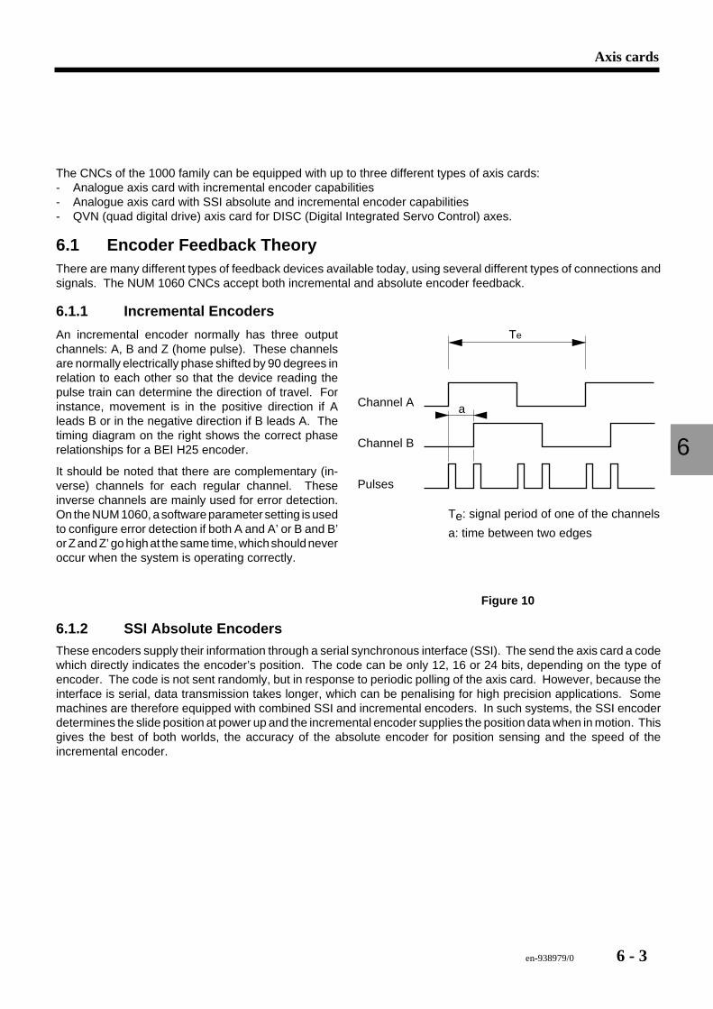
en-938979/0 6 - 3
Axis cards
6
The CNCs of the 1000 family can be equipped with up to three different types of axis cards:- Analogue axis card with incremental encoder capabilities- Analogue axis card with SSI absolute and incremental encoder capabilities- QVN (quad digital drive) axis card for DISC (Digital Integrated Servo Control) axes.
6.1 Encoder Feedback TheoryThere are many different types of feedback devices available today, using several different types of connections andsignals. The NUM 1060 CNCs accept both incremental and absolute encoder feedback.
6.1.1 Incremental Encoders
Channel A
Channel B
Pulses
Te: signal period of one of the channels
a: time between two edges
a
TeAn incremental encoder normally has three outputchannels: A, B and Z (home pulse). These channelsare normally electrically phase shifted by 90 degrees inrelation to each other so that the device reading thepulse train can determine the direction of travel. Forinstance, movement is in the positive direction if Aleads B or in the negative direction if B leads A. Thetiming diagram on the right shows the correct phaserelationships for a BEI H25 encoder.
It should be noted that there are complementary (in-verse) channels for each regular channel. Theseinverse channels are mainly used for error detection.On the NUM 1060, a software parameter setting is usedto configure error detection if both A and A’ or B and B’or Z and Z’ go high at the same time, which should neveroccur when the system is operating correctly.
Figure 10
6.1.2 SSI Absolute EncodersThese encoders supply their information through a serial synchronous interface (SSI). The send the axis card a codewhich directly indicates the encoder’s position. The code can be only 12, 16 or 24 bits, depending on the type ofencoder. The code is not sent randomly, but in response to periodic polling of the axis card. However, because theinterface is serial, data transmission takes longer, which can be penalising for high precision applications. Somemachines are therefore equipped with combined SSI and incremental encoders. In such systems, the SSI encoderdetermines the slide position at power up and the incremental encoder supplies the position data when in motion. Thisgives the best of both worlds, the accuracy of the absolute encoder for position sensing and the speed of theincremental encoder.
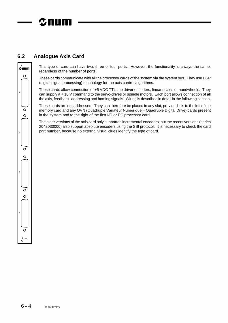
6 - 4 en-938979/0
6.2 Analogue Axis Card
Axes
4
3
2
1
This type of card can have two, three or four ports. However, the functionality is always the same,regardless of the number of ports.
These cards communicate with all the processor cards of the system via the system bus. They use DSP(digital signal processing) technology for the axis control algorithms.
These cards allow connection of +5 VDC TTL line driver encoders, linear scales or handwheels. Theycan supply a + 10 V command to the servo-drives or spindle motors. Each port allows connection of allthe axis, feedback, addressing and homing signals. Wiring is described in detail in the following section.
These cards are not addressed. They can therefore be placed in any slot, provided it is to the left of thememory card and any QVN (Quadruple Variateur Numérique = Quadruple Digital Drive) cards presentin the system and to the right of the first I/O or PC processor card.
The older versions of the axis card only supported incremental encoders, but the recent versions (series2042030000) also support absolute encoders using the SSI protocol. It is necessary to check the cardpart number, because no external visual clues identify the type of card.
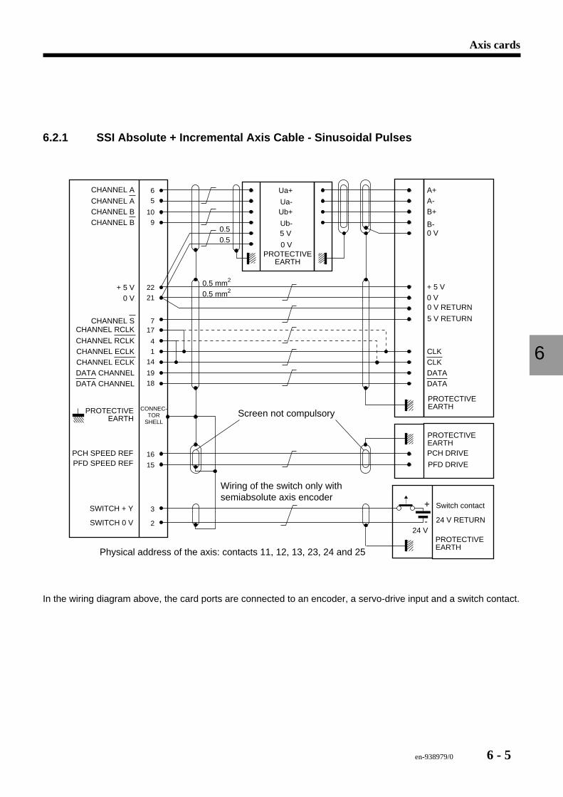
en-938979/0 6 - 5
Axis cards
6
6.2.1 SSI Absolute + Incremental Axis Cable - Sinusoidal Pulses
CHANNEL RCLKCHANNEL ECLKCHANNEL ECLKDATA CHANNELDATA CHANNEL
17
4
1
14
19
18
22
21+ 5 V
0 V
7
0.5 mm2
0.5 mm2+ 5 V0 V
16
15
3
2
+
-24 V
CHANNEL RCLKCHANNEL S
CLKCLKDATADATA
Ua+
Ua-Ub+
Ub-5 V
0 V
10
9
6
5CHANNEL ACHANNEL BCHANNEL B
CHANNEL A
0 V
A+A-B+
B-0.50.5
Wiring of the switch only with semiabsolute axis encoder
0 V RETURN
PCH DRIVE
PFD DRIVE
Switch contact
24 V RETURN
SWITCH + Y
SWITCH 0 V
5 V RETURN
Screen not compulsory
Physical address of the axis: contacts 11, 12, 13, 23, 24 and 25
PROTECTIVEEARTH
PROTECTIVEEARTHCONNEC-
TORSHELL
PROTECTIVEEARTH
PROTECTIVEEARTH
PROTECTIVEEARTH
PCH SPEED REFPFD SPEED REF
In the wiring diagram above, the card ports are connected to an encoder, a servo-drive input and a switch contact.
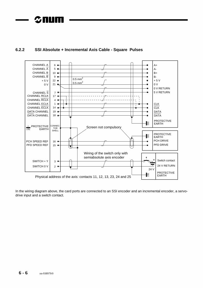
6 - 6 en-938979/0
6.2.2 SSI Absolute + Incremental Axis Cable - Square Pulses
22
21+ 5 V
0 V
0.5 mm2
0.5 mm2+ 5 V0 V
10
9
6
5A+A-B+B-
717
4
1
14
19
18
16
15
3
2
+
-24 V
CLKCLK
CHANNEL ACHANNEL BCHANNEL B
PCH DRIVE
PFD DRIVE
Switch contact
24 V RETURN
SWITCH + Y
SWITCH 0 V
CHANNEL A
Screen not compulsory
Physical address of the axis: contacts 11, 12, 13, 23, 24 and 25
PROTECTIVEEARTH
PROTECTIVEEARTH
CONNEC-TOR
SHELL
PROTECTIVEEARTH
PROTECTIVEEARTH
DATADATA
CHANNEL RCLKCHANNEL ECLKCHANNEL ECLKDATA CHANNELDATA CHANNEL
CHANNEL RCLKCHANNEL S
Wiring of the switch only with semiabsolute axis encoder
0 V RETURN5 V RETURN
PCH SPEED REFPFD SPEED REF
In the wiring diagram above, the card ports are connected to an SSI encoder and an incremental encoder, a servo-drive input and a switch contact.
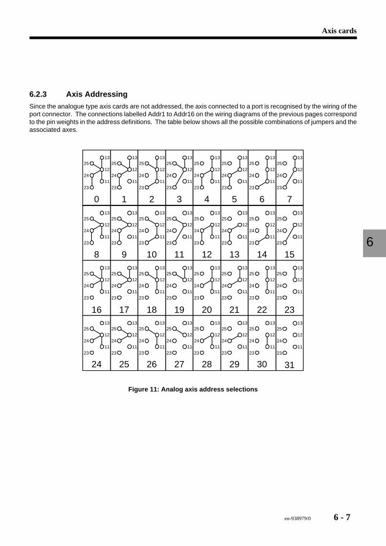
en-938979/0 6 - 7
Axis cards
6
6.2.3 Axis Addressing
Since the analogue type axis cards are not addressed, the axis connected to a port is recognised by the wiring of theport connector. The connections labelled Addr1 to Addr16 on the wiring diagrams of the previous pages correspondto the pin weights in the address definitions. The table below shows all the possible combinations of jumpers and theassociated axes.
0
25
24
2311
12
13
1
25
24
2311
12
13
2
25
24
2311
12
13
3
25
24
2311
12
13
4
25
24
2311
12
13
5
25
24
2311
12
13
6
25
24
2311
12
13
7
25
24
2311
12
13
8
25
24
2311
12
13
9
25
24
2311
12
13
10
25
24
2311
12
13
11
25
24
2311
12
13
12
25
24
2311
12
13
13
25
24
2311
12
13
14
25
24
2311
12
13
15
25
24
2311
12
13
16
25
24
2311
12
13
17
25
24
2311
12
13
18
25
24
2311
12
13
19
25
24
2311
12
13
20
25
24
2311
12
13
21
25
24
2311
12
13
22
25
24
2311
12
13
23
25
24
2311
12
13
24
25
24
2311
12
13
25
25
24
2311
12
13
26
25
24
2311
12
13
27
25
24
2311
12
13
28
25
24
2311
12
13
29
25
24
2311
12
13
30
25
24
2311
12
13
31
25
24
2311
12
13
Figure 11: Analog axis address selections
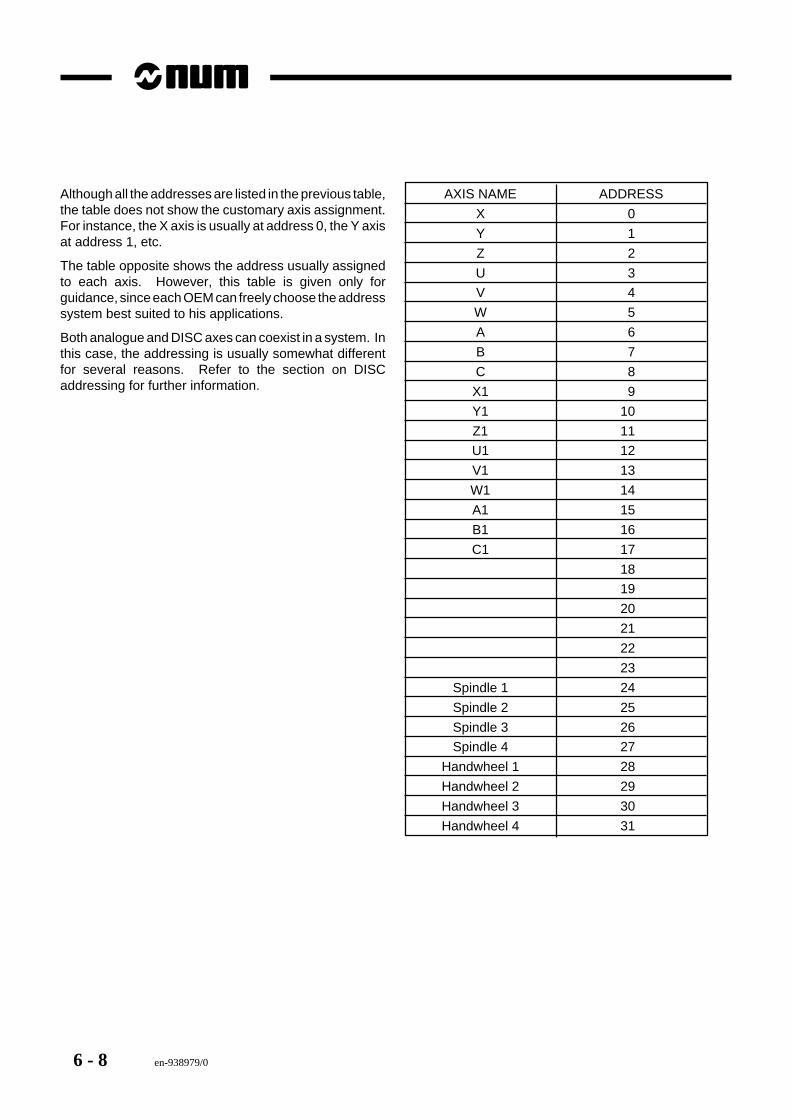
6 - 8 en-938979/0
Although all the addresses are listed in the previous table,the table does not show the customary axis assignment.For instance, the X axis is usually at address 0, the Y axisat address 1, etc.
The table opposite shows the address usually assignedto each axis. However, this table is given only forguidance, since each OEM can freely choose the addresssystem best suited to his applications.
Both analogue and DISC axes can coexist in a system. Inthis case, the addressing is usually somewhat differentfor several reasons. Refer to the section on DISCaddressing for further information.
AXIS NAME ADDRESS
X 0
Y 1
Z 2
U 3
V 4
W 5
A 6
B 7
C 8
X1 9
Y1 10
Z1 11
U1 12
V1 13
W1 14
A1 15
B1 16
C1 17
18
19
20
21
22
23
Spindle 1 24
Spindle 2 25
Spindle 3 26
Spindle 4 27
Handwheel 1 28
Handwheel 2 29
Handwheel 3 30
Handwheel 4 31
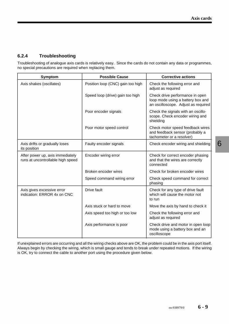
en-938979/0 6 - 9
Axis cards
6
6.2.4 Troubleshooting
Troubleshooting of analogue axis cards is relatively easy. Since the cards do not contain any data or programmes,no special precautions are required when replacing them.
Symptom Possible Cause Corrective actions
Axis shakes (oscillates) Position loop (CNC) gain too high Check the following error andadjust as required
Speed loop (drive) gain too high Check drive performance in openloop mode using a battery box andan oscilloscope. Adjust as required
Poor encoder signals Check the signals with an oscillo-scope. Check encoder wiring andshielding
Poor motor speed control Check motor speed feedback wiresand feedback sensor (probably atachometer or a resolver)
Axis drifts or gradually loses Faulty encoder signals Check encoder wiring and shieldingits position
After power up, axis immediately Encoder wiring error Check for correct encoder phasingruns at uncontrollable high speed and that the wires are correctly
connected
Broken encoder wires Check for broken encoder wires
Speed command wiring error Check speed command for correctphasing
Axis gives excessive error Drive fault Check for any type of drive faultindication: ERROR 4x on CNC which will cause the motor not
to run
Axis stuck or hard to move Move the axis by hand to check it
Axis speed too high or too low Check the following error andadjust as required
Axis performance is poor Check drive and motor in open loopmode using a battery box and anoscilloscope
If unexplained errors are occurring and all the wiring checks above are OK, the problem could be in the axis port itself.Always begin by checking the wiring, which is small gauge and tends to break under repeated motions. If the wiringis OK, try to connect the cable to another port using the procedure given below.
6 - 10 en-938979/0
Checking an Axis Port
1. Power down the machine and the CNC.2. Remove the cable from the suspected bad port.3. Connect the cable to another analogue port. If there are no free ports, remove another cable from a good port
and swap the two cables.4. After reattaching the cables, power up the machine and the CNC. Test the axis where the problem was found.
If the problem has disappeared, the port is probably faulty and the card should be replaced. However, if theproblem persists on this axis, the original port is OK and the cause of the problem is elsewhere.
6.2.5 Replacing the Card
Before beginning, make sure a replacement card is available.
1. Power down the CNC system and the machine.2. Remove all the connections from the card.3. Loosen the two card attaching screws, one at the top and one at the bottom.4. Gently pull out the card to unplug it from the rack.5. Install the new card in the rack and moderately tighten the attaching screws.6. Reinstall all the connections removed above.7. Power up the machine, then the CNC.
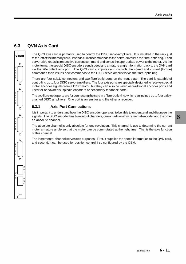
en-938979/0 6 - 11
Axis cards
6
6.3 QVN Axis Card
QVN
EMI
REC
VAR
CAPT0
CAPT1
CAPT2
CAPT3
The QVN axis card is primarily used to control the DISC servo-amplifiers. It is installed in the rack justto the left of the memory card. It sends current commands to the servo-drives via the fibre-optic ring. Eachservo-drive reads its respective current command and sends the appropriate power to the motor. As themotor turns, the special DISC encoders send speed and armature angle information back to the QVN cardvia the 26-contact axis port. The QVN card computes and controls the speed and current (torque)commands then issues new commands to the DISC servo-amplifiers via the fibre-optic ring.
There are four sub.D connectors and two fibre-optic ports on the front plate. The card is capable ofcontrolling up to four DISC servo-amplifiers. The four axis ports are specially designed to receive specialmotor encoder signals from a DISC motor, but they can also be wired as traditional encoder ports andused for handwheels, spindle encoders or secondary feedback ports.
The two fibre-optic ports are for connecting the card in a fibre-optic ring, which can include up to four daisy-chained DISC amplifiers. One port is an emitter and the other a receiver.
6.3.1 Axis Port Connections
It is important to understand how the DISC encoder operates, to be able to understand and diagnose thesignals. The DISC encoder has two output channels, one a traditional incremental encoder and the otheran absolute channel.
The absolute channel is only absolute for one revolution. This channel is use to determine the currentmotor armature angle so that the motor can be commutated at the right time. That is the sole functionof this channel.
The incremental channel serves two purposes. First, it supplies the speed information to the QVN card,and second, it can be used for position control if so configured by the OEM.
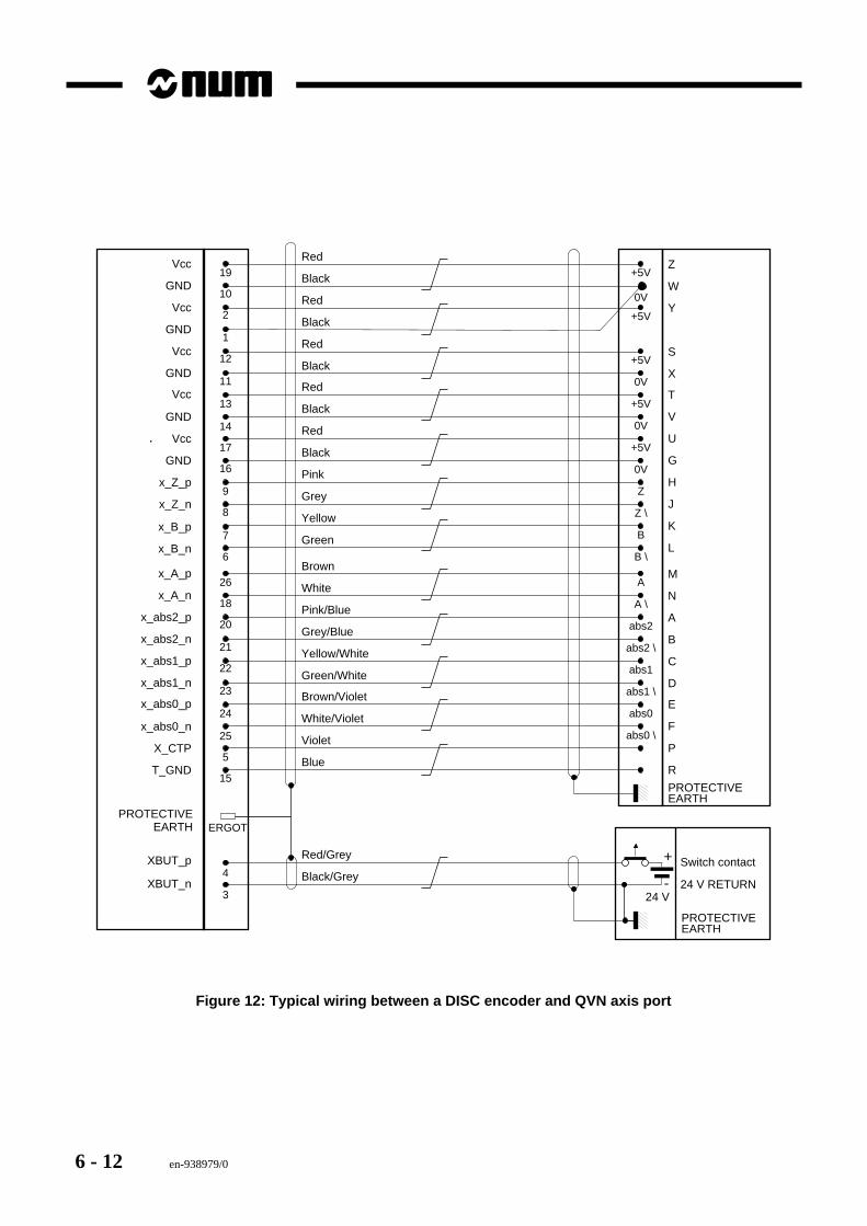
6 - 12 en-938979/0
19Vcc
GND
Vcc
GND
Vcc
GNDRed
GND
Vcc
GND
x_Z_p
x_Z_n
10
2
1
12
11
13
14
17
16
9
8
7
6
+5VT
x_B_p
x_B_n
0V
+5V
0V
Z
Z \
B
B \
Black
Red
Black
Pink
Grey
Yellow
Green
V
U
G
H
J
K
L
4
3
+
-
Switch contact
24 V RETURN
PROTECTIVEEARTH
XBUT_p
XBUT_n24 V
Vcc
Red
Black
Red
Black
Red
Black
+5V
0V
+5V
+5V
0V
Z
W
Y
S
X
26x_A_p
x_A_n
x_abs2_p
x_abs2_n
x_abs1_p
x_abs1_nBrown/Violet
x_abs0_n
X_CTP
T_GND
18
20
21
22
23
24
25
5
15
abs0E
abs0 \
White/Violet
Violet
Blue
F
P
R
x_abs0_p
Brown
White
Pink/Blue
Grey/Blue
Yellow/White
Green/White
A
A \
abs2
abs2 \
abs1
abs1 \
M
N
A
B
C
D
ERGOTPROTECTIVE
EARTH
Red/Grey
Black/Grey
PROTECTIVEEARTH
Figure 12: Typical wiring between a DISC encoder and QVN axis port
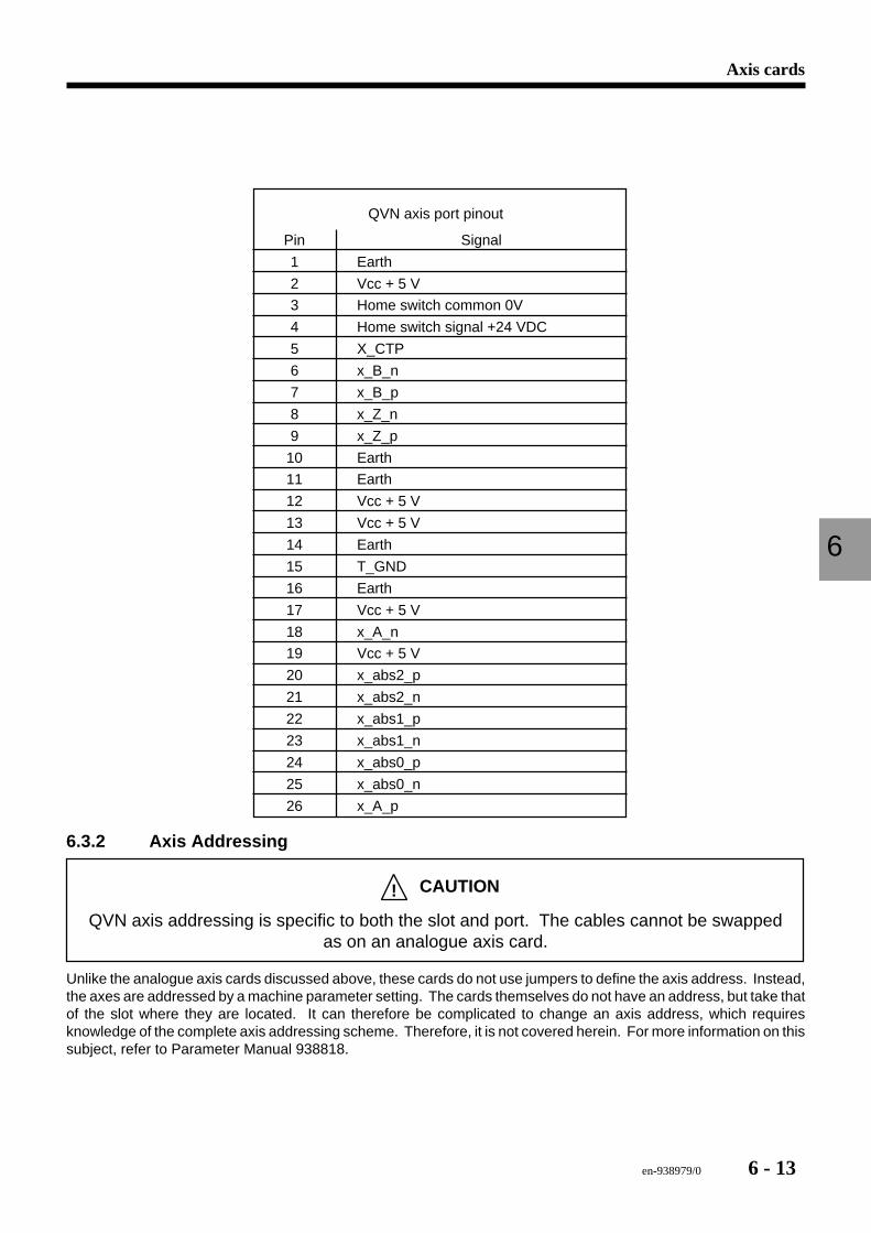
en-938979/0 6 - 13
Axis cards
6
QVN axis port pinout
Pin Signal
1 Earth
2 Vcc + 5 V
3 Home switch common 0V
4 Home switch signal +24 VDC
5 X_CTP
6 x_B_n
7 x_B_p
8 x_Z_n
9 x_Z_p
10 Earth
11 Earth
12 Vcc + 5 V
13 Vcc + 5 V
14 Earth
15 T_GND
16 Earth
17 Vcc + 5 V
18 x_A_n
19 Vcc + 5 V
20 x_abs2_p
21 x_abs2_n
22 x_abs1_p
23 x_abs1_n
24 x_abs0_p
25 x_abs0_n
26 x_A_p
6.3.2 Axis Addressing
! CAUTION
QVN axis addressing is specific to both the slot and port. The cables cannot be swappedas on an analogue axis card.
Unlike the analogue axis cards discussed above, these cards do not use jumpers to define the axis address. Instead,the axes are addressed by a machine parameter setting. The cards themselves do not have an address, but take thatof the slot where they are located. It can therefore be complicated to change an axis address, which requiresknowledge of the complete axis addressing scheme. Therefore, it is not covered herein. For more information on thissubject, refer to Parameter Manual 938818.
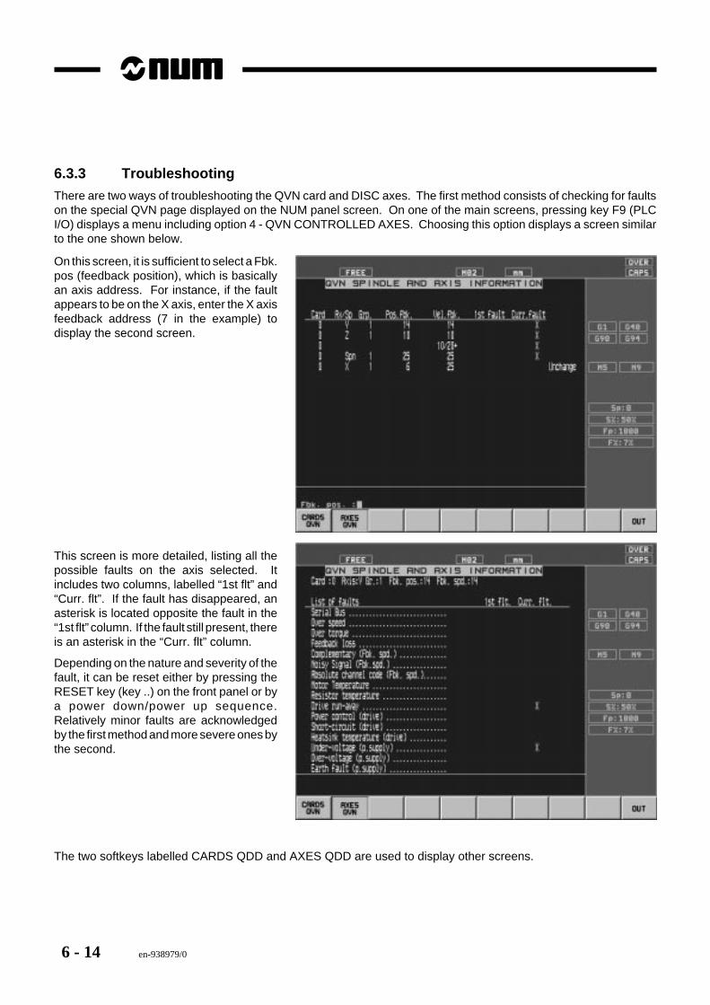
6 - 14 en-938979/0
6.3.3 Troubleshooting
There are two ways of troubleshooting the QVN card and DISC axes. The first method consists of checking for faultson the special QVN page displayed on the NUM panel screen. On one of the main screens, pressing key F9 (PLCI/O) displays a menu including option 4 - QVN CONTROLLED AXES. Choosing this option displays a screen similarto the one shown below.
On this screen, it is sufficient to select a Fbk.pos (feedback position), which is basicallyan axis address. For instance, if the faultappears to be on the X axis, enter the X axisfeedback address (7 in the example) todisplay the second screen.
This screen is more detailed, listing all thepossible faults on the axis selected. Itincludes two columns, labelled “1st flt” and“Curr. flt”. If the fault has disappeared, anasterisk is located opposite the fault in the“1st flt” column. If the fault still present, thereis an asterisk in the “Curr. flt” column.
Depending on the nature and severity of thefault, it can be reset either by pressing theRESET key (key ..) on the front panel or bya power down/power up sequence.Relatively minor faults are acknowledgedby the first method and more severe ones bythe second.
The two softkeys labelled CARDS QDD and AXES QDD are used to display other screens.
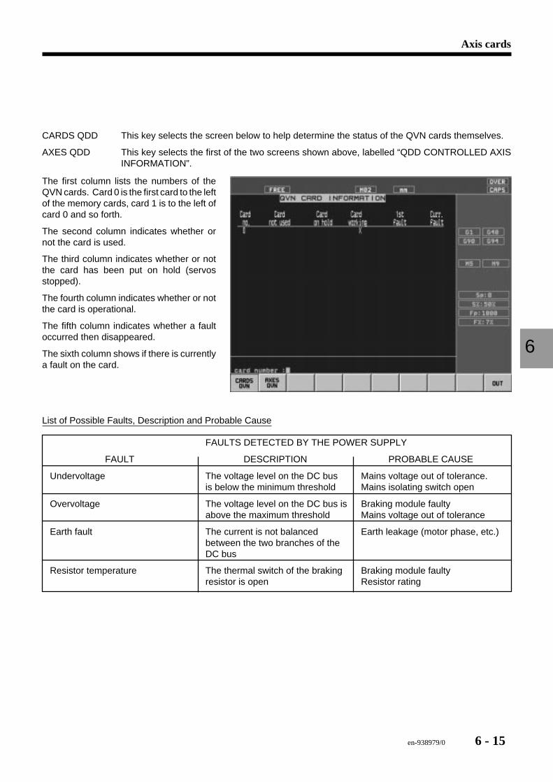
en-938979/0 6 - 15
Axis cards
6
CARDS QDD This key selects the screen below to help determine the status of the QVN cards themselves.
AXES QDD This key selects the first of the two screens shown above, labelled “QDD CONTROLLED AXISINFORMATION”.
The first column lists the numbers of theQVN cards. Card 0 is the first card to the leftof the memory cards, card 1 is to the left ofcard 0 and so forth.
The second column indicates whether ornot the card is used.
The third column indicates whether or notthe card has been put on hold (servosstopped).
The fourth column indicates whether or notthe card is operational.
The fifth column indicates whether a faultoccurred then disappeared.
The sixth column shows if there is currentlya fault on the card.
List of Possible Faults, Description and Probable Cause
FAULTS DETECTED BY THE POWER SUPPLY
FAULT DESCRIPTION PROBABLE CAUSE
Undervoltage The voltage level on the DC bus Mains voltage out of tolerance.is below the minimum threshold Mains isolating switch open
Overvoltage The voltage level on the DC bus is Braking module faultyabove the maximum threshold Mains voltage out of tolerance
Earth fault The current is not balanced Earth leakage (motor phase, etc.)between the two branches of theDC bus
Resistor temperature The thermal switch of the braking Braking module faultyresistor is open Resistor rating
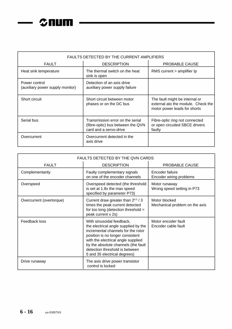
6 - 16 en-938979/0
FAULTS DETECTED BY THE CURRENT AMPLIFIERS
FAULT DESCRIPTION PROBABLE CAUSE
Heat sink temperature The thermal switch on the heat RMS current > amplifier Ipsink is open
Power control Detection of an axis drive(auxiliary power supply monitor) auxiliary power supply failure
Short circuit Short circuit between motor The fault might be internal orphases or on the DC bus external ato the module. Check the
motor power leads for shorts
Serial bus Transmission error on the serial Fibre-optic ring not connected(fibre-optic) bus between the QVN or open circuited SBCE driverscard and a servo-drive faulty
Overcurrent Overcurrent detected in theaxis drive
FAULTS DETECTED BY THE QVN CARDS
FAULT DESCRIPTION PROBABLE CAUSE
Complementarity Faulty complementary signals Encoder failureon one of the encoder channels Encoder wiring problems
Overspeed Overspeed detected (the threshold Motor runawayis set at 1.8x the max speed Wrong speed setting in P73specified by parameter P73)
Overcurrent (overtorque) Current draw greater than 20.5 / 3 Motor blockedtimes the peak current detected Mechanical problem on the axisfor too long (detection threshold =peak current x 2s)
Feedback loss With sinusoidal feedback, Motor encoder faultthe electrical angle supplied by the Encoder cable faultincremental channels for the rotorposition is no longer consistentwith the electrical angle suppliedby the absolute channels (the faultdetection threshold is between5 and 35 electrical degrees)
Drive runaway The axis drive power transistor control is locked
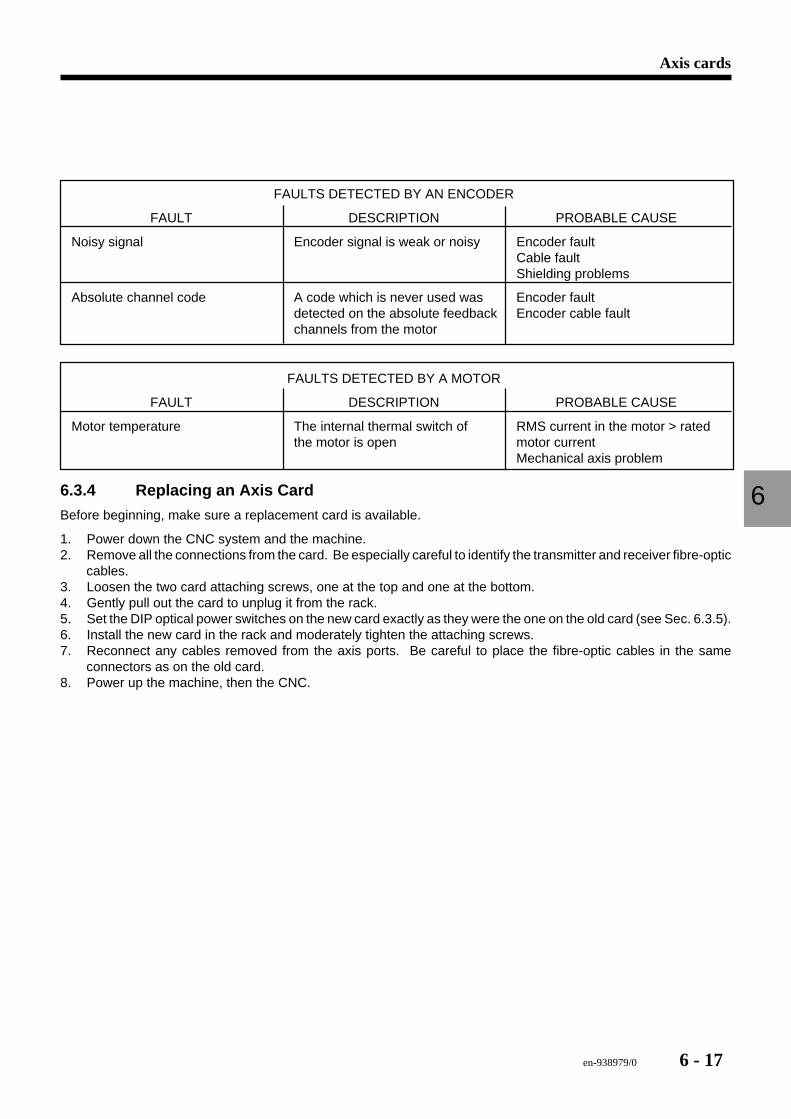
en-938979/0 6 - 17
Axis cards
6
FAULTS DETECTED BY AN ENCODER
FAULT DESCRIPTION PROBABLE CAUSE
Noisy signal Encoder signal is weak or noisy Encoder faultCable faultShielding problems
Absolute channel code A code which is never used was Encoder faultdetected on the absolute feedback Encoder cable faultchannels from the motor
FAULTS DETECTED BY A MOTOR
FAULT DESCRIPTION PROBABLE CAUSE
Motor temperature The internal thermal switch of RMS current in the motor > ratedthe motor is open motor current
Mechanical axis problem
6.3.4 Replacing an Axis Card
Before beginning, make sure a replacement card is available.
1. Power down the CNC system and the machine.2. Remove all the connections from the card. Be especially careful to identify the transmitter and receiver fibre-optic
cables.3. Loosen the two card attaching screws, one at the top and one at the bottom.4. Gently pull out the card to unplug it from the rack.5. Set the DIP optical power switches on the new card exactly as they were the one on the old card (see Sec. 6.3.5).6. Install the new card in the rack and moderately tighten the attaching screws.7. Reconnect any cables removed from the axis ports. Be careful to place the fibre-optic cables in the same
connectors as on the old card.8. Power up the machine, then the CNC.
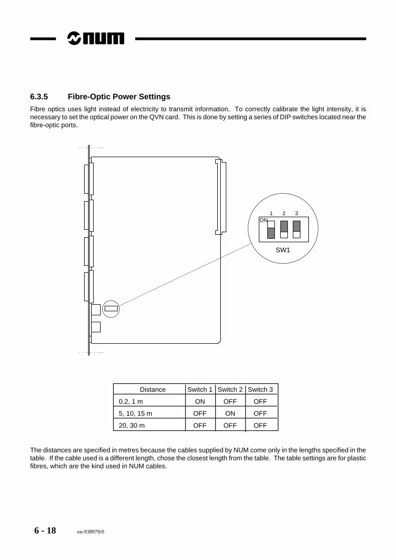
6 - 18 en-938979/0
6.3.5 Fibre-Optic Power Settings
Fibre optics uses light instead of electricity to transmit information. To correctly calibrate the light intensity, it isnecessary to set the optical power on the QVN card. This is done by setting a series of DIP switches located near thefibre-optic ports.
SW1
ON1 2 3
Distance Switch 1 Switch 2 Switch 3
0.2, 1 m ON OFF OFF
5, 10, 15 m OFF ON OFF
20, 30 m OFF OFF OFF
The distances are specified in metres because the cables supplied by NUM come only in the lengths specified in thetable. If the cable used is a different length, chose the closest length from the table. The table settings are for plasticfibres, which are the kind used in NUM cables.
en-938979/0 7 - 1
Input/Output Cards
7
7 Input/Output Cards
7.1 I/O Card Display and Troubleshooting 7 - 37.1.1 Input/Output Display 7 - 4
7.2 32-Input Card 7 - 57.2.1 Input Wiring 7 - 67.2.2 Replacing the Card 7 - 7
7.3 32-Output Card 7 - 77.3.1 Output Wiring 7 - 87.3.2 Replacing the Card 7 - 9
7.4 32-Input/24-Output Card (with Sub.D connectors) 7 - 107.4.1 Input Wiring 7 - 117.4.2 Output Wiring 7 - 127.4.3 External Power Connector 7 - 137.4.4 Replacing the Card 7 - 13
7.5 32-24 I/O Card (with high density connectors) 7 - 147.5.1 Replacing the Card 7 - 14
7.6 64-48 I/O Card (with high density connectors) 7 - 157.6.1 Replacing the Card 7 - 15
7.7 32-Input Interface Panel 7 - 167.7.1 Replacing the Panel 7 - 16
7.8 24-Output Relay Panel 7 - 177.8.1 Replacing the Panel 7 - 17

7 - 2 en-938979/0
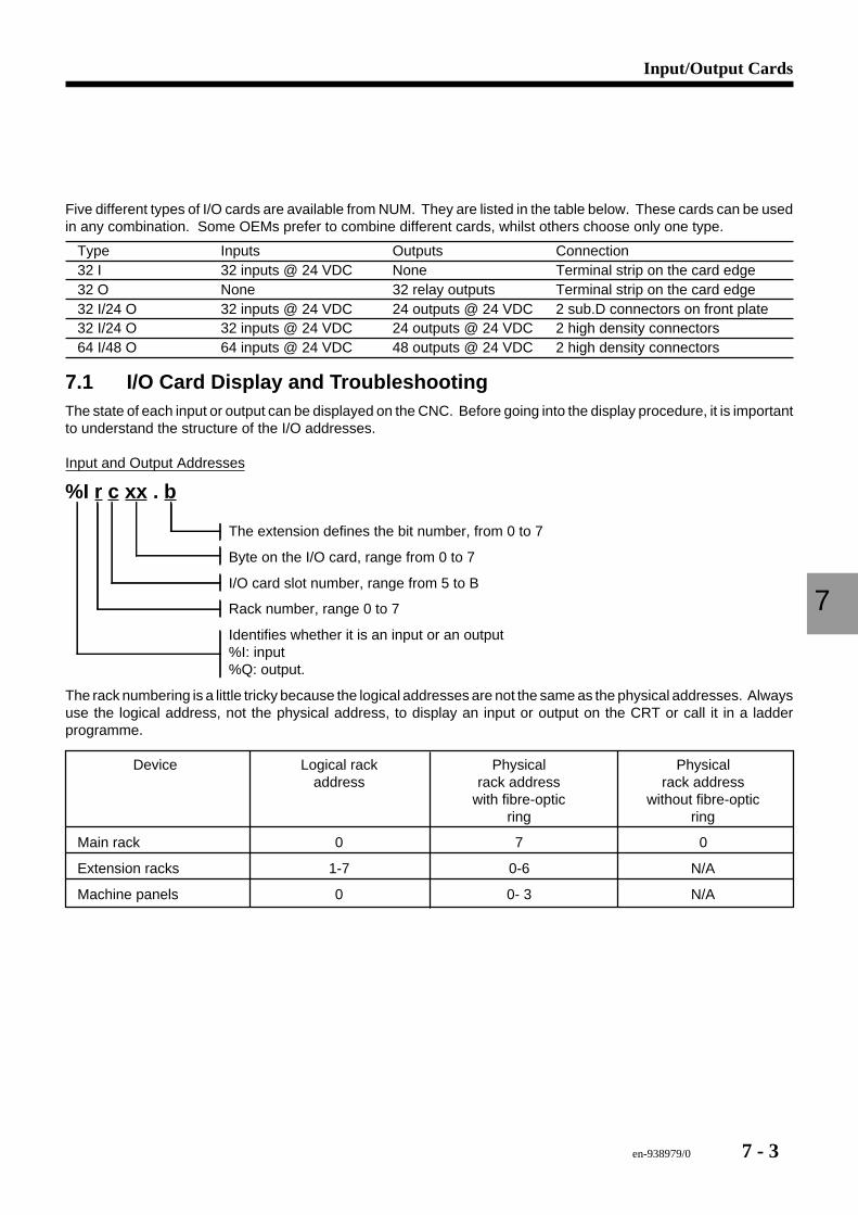
en-938979/0 7 - 3
Input/Output Cards
7
Five different types of I/O cards are available from NUM. They are listed in the table below. These cards can be usedin any combination. Some OEMs prefer to combine different cards, whilst others choose only one type.
Type Inputs Outputs Connection32 I 32 inputs @ 24 VDC None Terminal strip on the card edge32 O None 32 relay outputs Terminal strip on the card edge32 I/24 O 32 inputs @ 24 VDC 24 outputs @ 24 VDC 2 sub.D connectors on front plate32 I/24 O 32 inputs @ 24 VDC 24 outputs @ 24 VDC 2 high density connectors64 I/48 O 64 inputs @ 24 VDC 48 outputs @ 24 VDC 2 high density connectors
7.1 I/O Card Display and TroubleshootingThe state of each input or output can be displayed on the CNC. Before going into the display procedure, it is importantto understand the structure of the I/O addresses.
Input and Output Addresses
%I r c xx . b
The extension defines the bit number, from 0 to 7
Byte on the I/O card, range from 0 to 7
I/O card slot number, range from 5 to B
Rack number, range 0 to 7
Identifies whether it is an input or an output%I: input%Q: output.
The rack numbering is a little tricky because the logical addresses are not the same as the physical addresses. Alwaysuse the logical address, not the physical address, to display an input or output on the CRT or call it in a ladderprogramme.
Device Logical rack Physical Physicaladdress rack address rack address
with fibre-optic without fibre-opticring ring
Main rack 0 7 0
Extension racks 1-7 0-6 N/A
Machine panels 0 0- 3 N/A
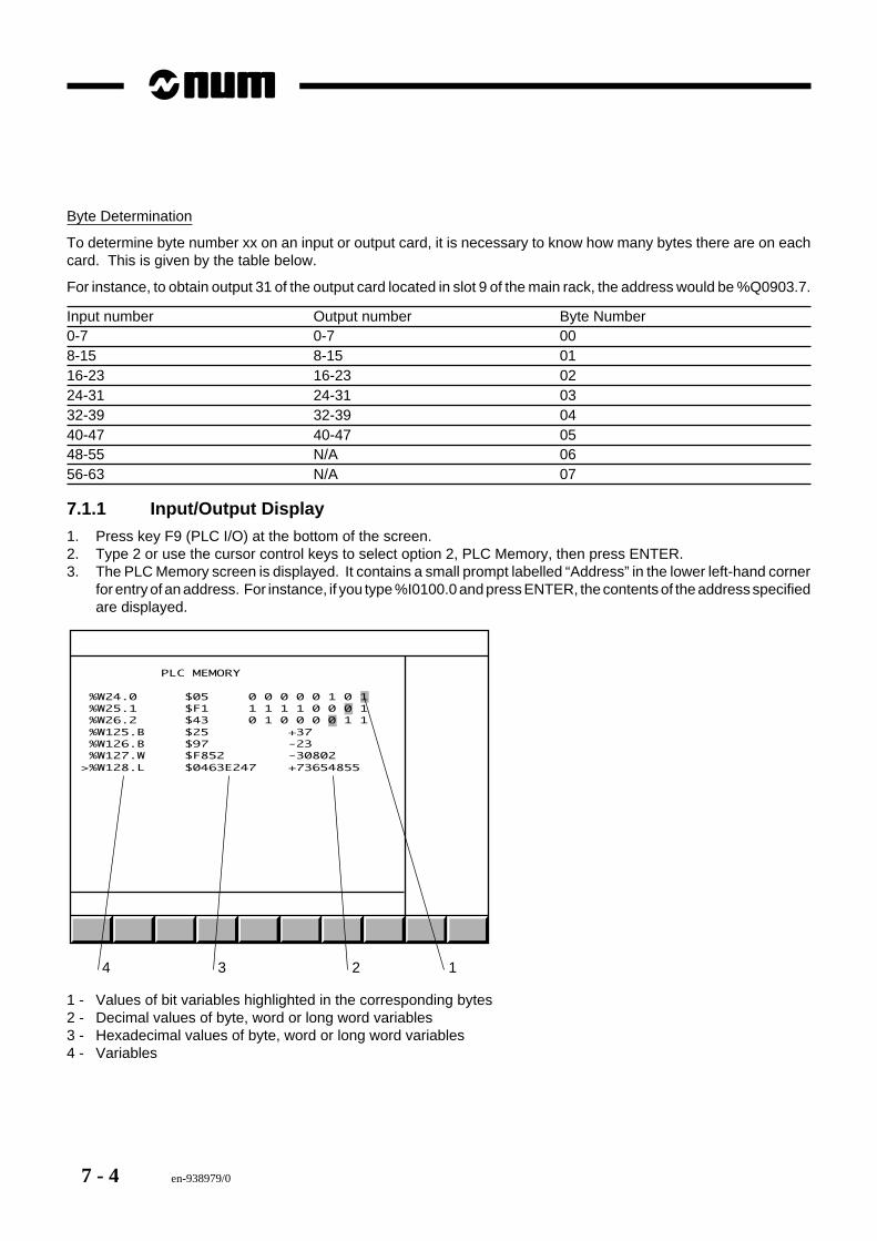
7 - 4 en-938979/0
Byte Determination
To determine byte number xx on an input or output card, it is necessary to know how many bytes there are on eachcard. This is given by the table below.
For instance, to obtain output 31 of the output card located in slot 9 of the main rack, the address would be %Q0903.7.
Input number Output number Byte Number0-7 0-7 008-15 8-15 0116-23 16-23 0224-31 24-31 0332-39 32-39 0440-47 40-47 0548-55 N/A 0656-63 N/A 07
7.1.1 Input/Output Display
1. Press key F9 (PLC I/O) at the bottom of the screen.2. Type 2 or use the cursor control keys to select option 2, PLC Memory, then press ENTER.3. The PLC Memory screen is displayed. It contains a small prompt labelled “Address” in the lower left-hand corner
for entry of an address. For instance, if you type %I0100.0 and press ENTER, the contents of the address specifiedare displayed.
4 3 2 1
PLC MEMORY
%W24.0 $05 0 0 0 0 0 1 0 1 %W25.1 $F1 1 1 1 1 0 0 0 1 %W26.2 $43 0 1 0 0 0 0 1 1 %W125.B $25 +37 %W126.B $97 -23 %W127.W $F852 -30802>%W128.L $0463E247 +73654855
1 - Values of bit variables highlighted in the corresponding bytes2 - Decimal values of byte, word or long word variables3 - Hexadecimal values of byte, word or long word variables4 - Variables
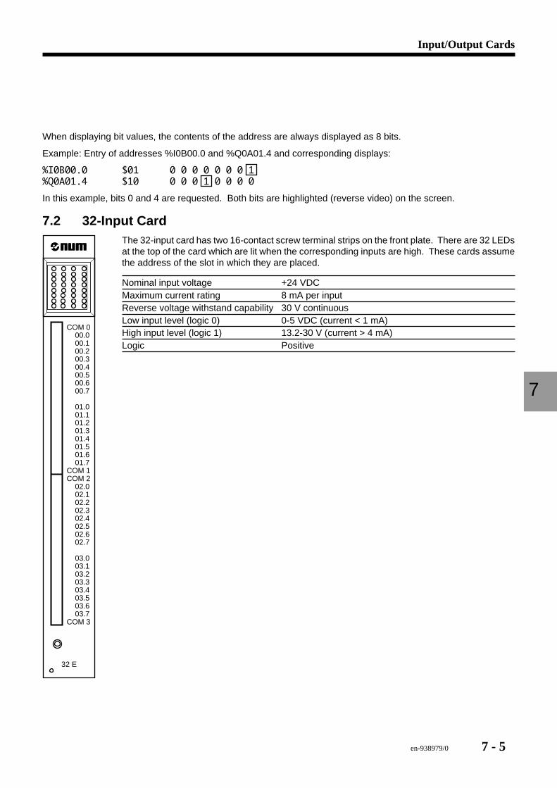
en-938979/0 7 - 5
Input/Output Cards
7
When displaying bit values, the contents of the address are always displayed as 8 bits.
Example: Entry of addresses %I0B00.0 and %Q0A01.4 and corresponding displays:
%I0B00.0 $01 0 0 0 0 0 0 0 1%Q0A01.4 $10 0 0 0 1 0 0 0 0
In this example, bits 0 and 4 are requested. Both bits are highlighted (reverse video) on the screen.
7.2 32-Input Card
32 E
COM 0 00.0 00.1 00.2 00.3 00.4 00.5 00.6 00.7
01.0 01.1 01.2 01.3 01.4 01.5 01.6 01.7COM 1COM 2 02.0 02.1 02.2 02.3 02.4 02.5 02.6 02.7
03.0 03.1 03.2 03.3 03.4 03.5 03.6 03.7 COM 3
The 32-input card has two 16-contact screw terminal strips on the front plate. There are 32 LEDsat the top of the card which are lit when the corresponding inputs are high. These cards assumethe address of the slot in which they are placed.
Nominal input voltage +24 VDCMaximum current rating 8 mA per inputReverse voltage withstand capability 30 V continuousLow input level (logic 0) 0-5 VDC (current < 1 mA)High input level (logic 1) 13.2-30 V (current > 4 mA)Logic Positive
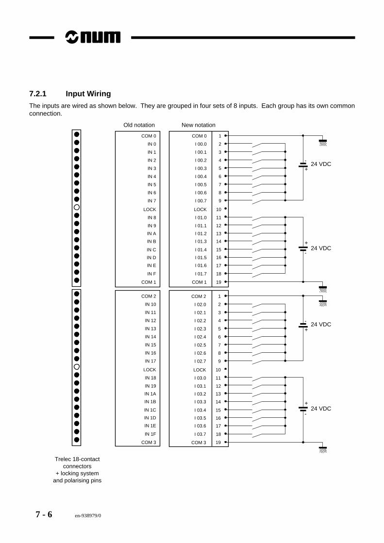
7 - 6 en-938979/0
7.2.1 Input Wiring
The inputs are wired as shown below. They are grouped in four sets of 8 inputs. Each group has its own commonconnection.
1COM 0
2IN 0
3IN 1
4IN 2
5IN 3
6IN 4
7IN 5
8IN 6
9IN 7
10LOCK
11IN 8
12IN 9
24 VDC
13
14
15
16
17
18
19
IN A
IN B
IN C
IN D
IN E
IN F
COM 1
COM 0
I 00.0
I 00.1
I 00.2
I 00.3
I 00.4
I 00.5
I 00.6
I 00.7
LOCK
I 01.0
I 01.1
I 01.2
I 01.3
I 01.4
I 01.5
I 01.6
I 01.7
COM 1
24 VDC+
+
-
-
1COM 2
2IN 10
3IN 11
4IN 12
5IN 13
6IN 14
7IN 15
8IN 16
9IN 17
10LOCK
11IN 18
12IN 19
24 VDC
13
14
15
16
17
18
19
IN 1A
IN 1B
IN 1C
IN 1D
IN 1E
IN 1F
COM 3
COM 2
I 02.0
I 02.1
I 02.2
I 02.3
I 02.4
I 02.5
I 02.6
I 02.7
LOCK
I 03.0
I 03.1
I 03.2
I 03.3
I 03.4
I 03.5
I 03.6
I 03.7
COM 3
24 VDC+
+
-
-
Trelec 18-contactconnectors
+ locking systemand polarising pins
Old notation New notation
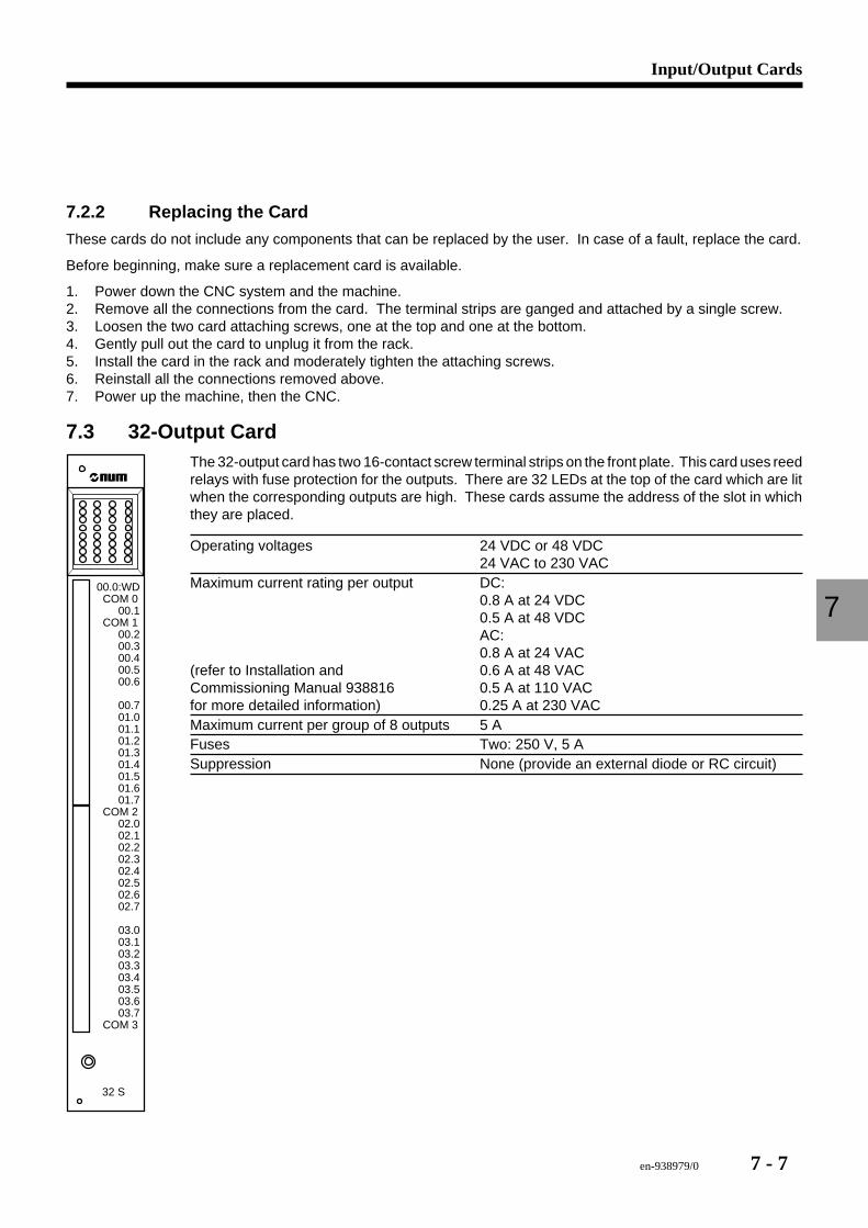
en-938979/0 7 - 7
Input/Output Cards
7
7.2.2 Replacing the Card
These cards do not include any components that can be replaced by the user. In case of a fault, replace the card.
Before beginning, make sure a replacement card is available.
1. Power down the CNC system and the machine.2. Remove all the connections from the card. The terminal strips are ganged and attached by a single screw.3. Loosen the two card attaching screws, one at the top and one at the bottom.4. Gently pull out the card to unplug it from the rack.5. Install the card in the rack and moderately tighten the attaching screws.6. Reinstall all the connections removed above.7. Power up the machine, then the CNC.
7.3 32-Output Card
32 S
00.0:WD COM 0 00.1 COM 1 00.2 00.3 00.4 00.5 00.6
00.7 01.0 01.1 01.2 01.3 01.4 01.5 01.6 01.7 COM 2 02.0 02.1 02.2 02.3 02.4 02.5 02.6 02.7
03.0 03.1 03.2 03.3 03.4 03.5 03.6 03.7 COM 3
The 32-output card has two 16-contact screw terminal strips on the front plate. This card uses reedrelays with fuse protection for the outputs. There are 32 LEDs at the top of the card which are litwhen the corresponding outputs are high. These cards assume the address of the slot in whichthey are placed.
Operating voltages 24 VDC or 48 VDC24 VAC to 230 VAC
Maximum current rating per output DC:0.8 A at 24 VDC0.5 A at 48 VDCAC:0.8 A at 24 VAC
(refer to Installation and 0.6 A at 48 VACCommissioning Manual 938816 0.5 A at 110 VACfor more detailed information) 0.25 A at 230 VACMaximum current per group of 8 outputs 5 AFuses Two: 250 V, 5 ASuppression None (provide an external diode or RC circuit)
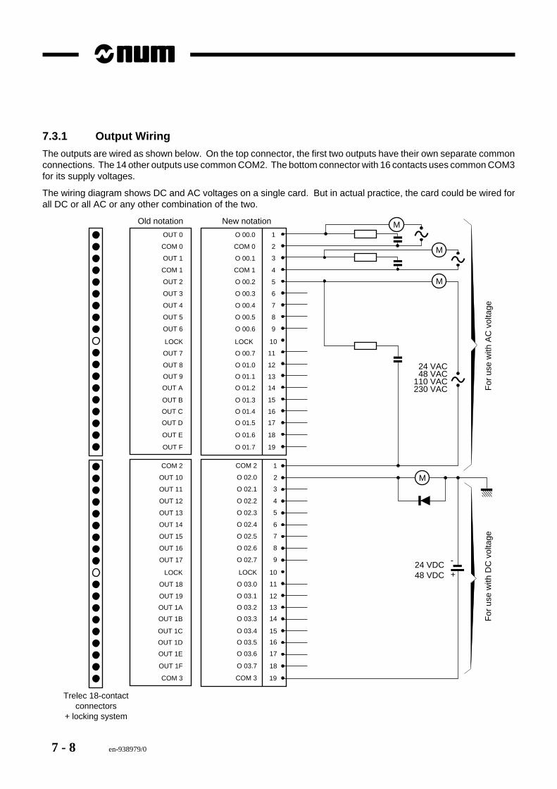
7 - 8 en-938979/0
7.3.1 Output Wiring
The outputs are wired as shown below. On the top connector, the first two outputs have their own separate commonconnections. The 14 other outputs use common COM2. The bottom connector with 16 contacts uses common COM3for its supply voltages.
The wiring diagram shows DC and AC voltages on a single card. But in actual practice, the card could be wired forall DC or all AC or any other combination of the two.
1OUT 0
2COM 0
3OUT 1
4COM 1
5OUT 2
6OUT 3
7OUT 4
8OUT 5
9OUT 6
10
11OUT 7
12OUT 8
13
14
15
16
17
18
19
OUT 9
OUT A
OUT B
OUT C
OUT D
OUT E
OUT F
O 00.0
COM 0
O 00.1
COM 1
O 00.2
O 00.3
O 00.4
O 00.5
O 00.6
O 00.7
O 01.0
O 01.1
O 01.2
O 01.3
O 01.4
O 01.5
O 01.6
O 01.7
1COM 2
2O 02.0
3O 02.1
4O 02.2
5O 02.3
6O 02.4
7O 02.5
8O 02.6
9O 02.7
10LOCK
11O 03.0
12O 03.1
13
14
15
16
17
18
19
O 03.2
O 03.3
O 03.4
O 03.5
O 03.6
O 03.7
COM 3
COM 2
OUT 10
OUT 11
OUT 12
OUT 13
OUT 14
OUT 15
OUT 16
OUT 17
LOCK
OUT 18
OUT 19
OUT 1A
OUT 1B
OUT 1C
OUT 1D
OUT 1E
OUT 1F
COM 3
24 VDC48 VDC
Trelec 18-contactconnectors
+ locking system
M
M
M
24 VAC48 VAC
110 VAC230 VAC
+
-
MF
or u
se w
ith A
C v
olta
geF
or u
se w
ith D
C v
olta
ge
LOCKLOCK
Old notation New notation

en-938979/0 7 - 9
Input/Output Cards
7
7.3.2 Replacing the Card
With the exception of the fuses, these cards do not include any components that can be replaced by the user. Alwayscheck the fuses first, before deciding the card is faulty. There are two fuses, one for each group of 16 outputs.
If after checking the fuses, the card is determined to be faulty, replace the complete card.
Before beginning, make sure a replacement card is available.
1. Power down the CNC system and the machine.2. Remove all the connections from the card. The terminal strips are ganged and attached by a single screw.3. Loosen the two card attaching screws, one at the top and one at the bottom.4. Gently pull out the card to unplug it from the rack.5. Install the card in the rack and moderately tighten the attaching screws.6. Reinstall all the connections removed above.7. Power up the machine, then the CNC.
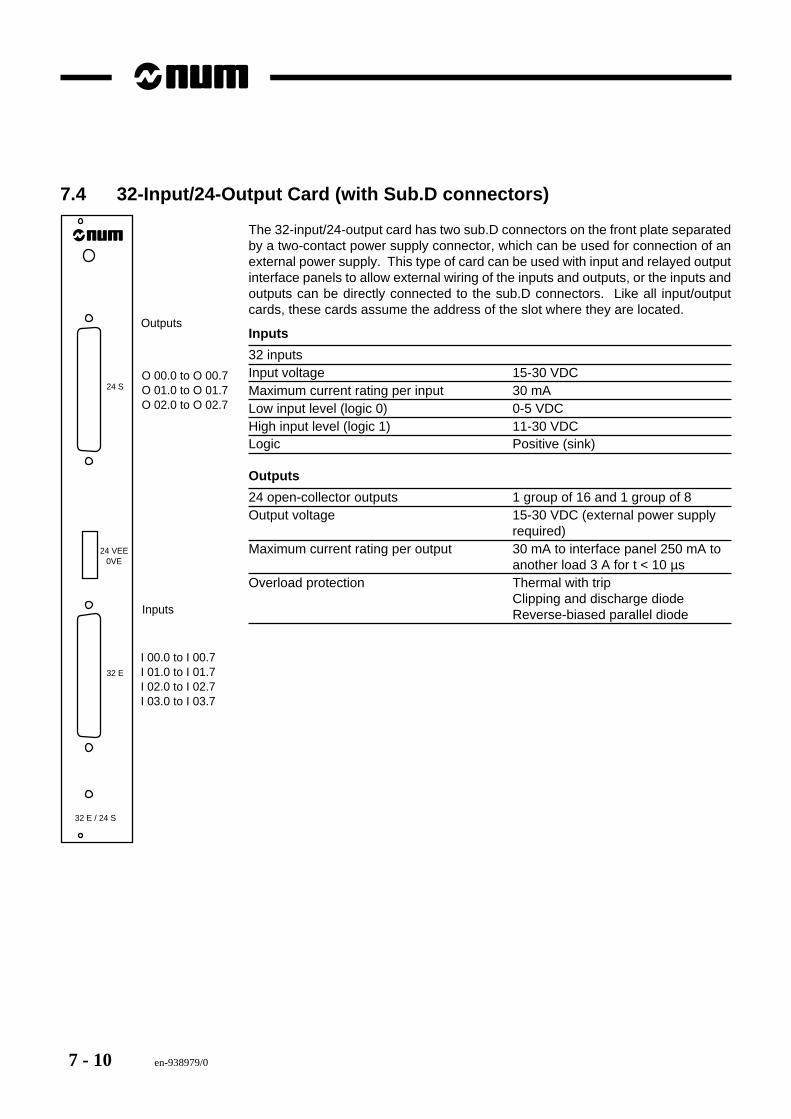
7 - 10 en-938979/0
7.4 32-Input/24-Output Card (with Sub.D connectors)
32 E / 24 S
32 E
24 S
24 VEE0VE
Inputs
I 00.0 to I 00.7I 01.0 to I 01.7I 02.0 to I 02.7I 03.0 to I 03.7
Outputs
O 00.0 to O 00.7O 01.0 to O 01.7O 02.0 to O 02.7
The 32-input/24-output card has two sub.D connectors on the front plate separatedby a two-contact power supply connector, which can be used for connection of anexternal power supply. This type of card can be used with input and relayed outputinterface panels to allow external wiring of the inputs and outputs, or the inputs andoutputs can be directly connected to the sub.D connectors. Like all input/outputcards, these cards assume the address of the slot where they are located.
Inputs
32 inputsInput voltage 15-30 VDCMaximum current rating per input 30 mALow input level (logic 0) 0-5 VDCHigh input level (logic 1) 11-30 VDCLogic Positive (sink)
Outputs
24 open-collector outputs 1 group of 16 and 1 group of 8Output voltage 15-30 VDC (external power supply
required)Maximum current rating per output 30 mA to interface panel 250 mA to
another load 3 A for t < 10 µsOverload protection Thermal with trip
Clipping and discharge diodeReverse-biased parallel diode
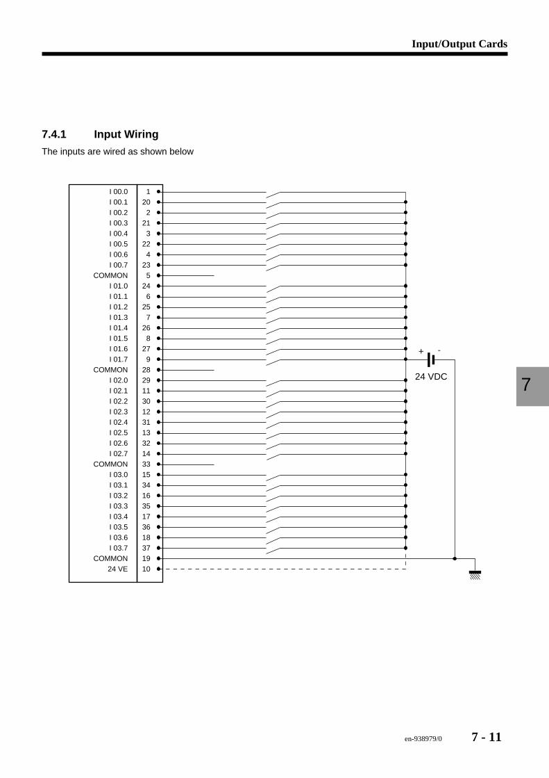
en-938979/0 7 - 11
Input/Output Cards
7
7.4.1 Input Wiring
The inputs are wired as shown below
24 VDC
+
1202
213
224
235
246
257
268
279
2829113012311332143315341635173618371910
I 00.0I 00.1I 00.2I 00.3I 00.4I 00.5I 00.6I 00.7
COMMON
COMMONI 02.0I 02.1I 02.2I 02.3I 02.4I 02.5I 02.6I 02.7
COMMON
COMMON24 VE
-
I 01.0I 01.1I 01.2I 01.3I 01.4I 01.5I 01.6I 01.7
I 03.0I 03.1I 03.2I 03.3I 03.4I 03.5I 03.6I 03.7
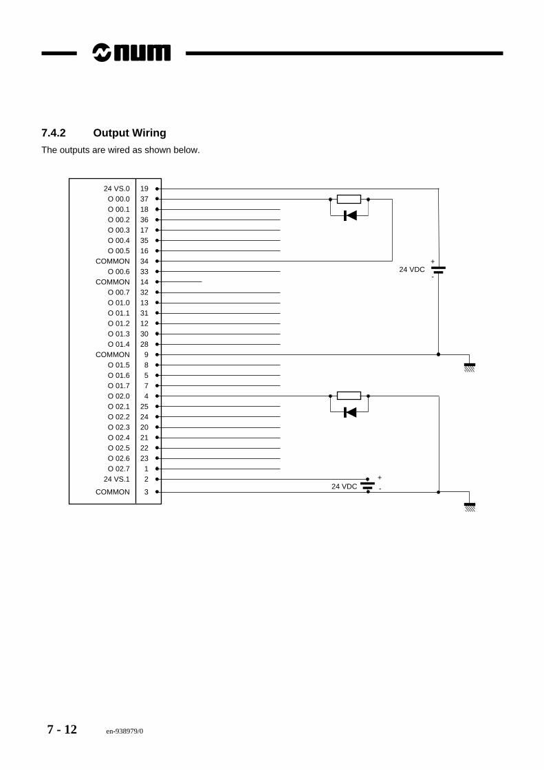
7 - 12 en-938979/0
7.4.2 Output Wiring
The outputs are wired as shown below.
24 VS.0 1937183617351634331432133112302898574
25242021222312
3
O 00.0O 00.1O 00.2O 00.3O 00.4O 00.5
COMMONO 00.6
COMMONO 00.7O 01.0O 01.1O 01.2O 01.3O 01.4
COMMONO 01.5O 01.6O 01.7O 02.0O 02.1O 02.2O 02.3O 02.4O 02.5O 02.6O 02.7
24 VS.1
COMMON
+
-24 VDC
+
-24 VDC
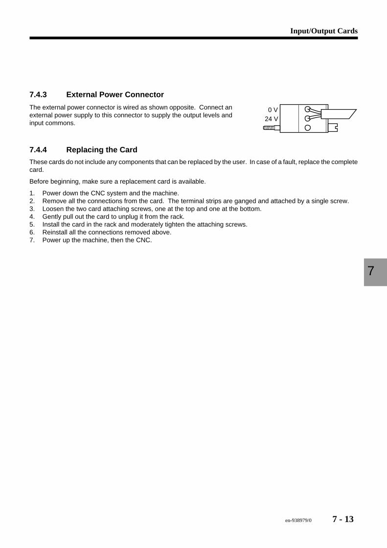
en-938979/0 7 - 13
Input/Output Cards
7
7.4.3 External Power Connector
0 V24 V
The external power connector is wired as shown opposite. Connect anexternal power supply to this connector to supply the output levels andinput commons.
7.4.4 Replacing the Card
These cards do not include any components that can be replaced by the user. In case of a fault, replace the completecard.
Before beginning, make sure a replacement card is available.
1. Power down the CNC system and the machine.2. Remove all the connections from the card. The terminal strips are ganged and attached by a single screw.3. Loosen the two card attaching screws, one at the top and one at the bottom.4. Gently pull out the card to unplug it from the rack.5. Install the card in the rack and moderately tighten the attaching screws.6. Reinstall all the connections removed above.7. Power up the machine, then the CNC.
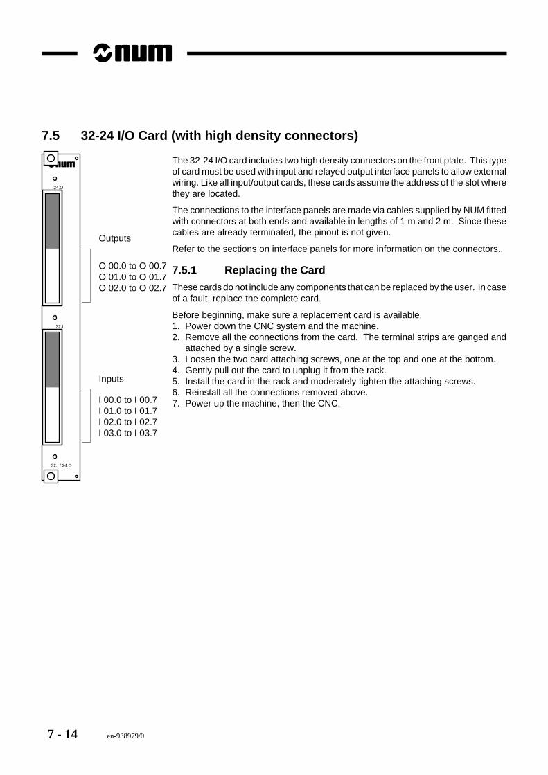
7 - 14 en-938979/0
7.5 32-24 I/O Card (with high density connectors)
O 00.0 to O 00.7O 01.0 to O 01.7O 02.0 to O 02.7
32.I / 24.O
32.I
24.O
I 00.0 to I 00.7I 01.0 to I 01.7I 02.0 to I 02.7I 03.0 to I 03.7
Inputs
Outputs
The 32-24 I/O card includes two high density connectors on the front plate. This typeof card must be used with input and relayed output interface panels to allow externalwiring. Like all input/output cards, these cards assume the address of the slot wherethey are located.
The connections to the interface panels are made via cables supplied by NUM fittedwith connectors at both ends and available in lengths of 1 m and 2 m. Since thesecables are already terminated, the pinout is not given.
Refer to the sections on interface panels for more information on the connectors..
7.5.1 Replacing the Card
These cards do not include any components that can be replaced by the user. In caseof a fault, replace the complete card.
Before beginning, make sure a replacement card is available.1. Power down the CNC system and the machine.2. Remove all the connections from the card. The terminal strips are ganged and
attached by a single screw.3. Loosen the two card attaching screws, one at the top and one at the bottom.4. Gently pull out the card to unplug it from the rack.5. Install the card in the rack and moderately tighten the attaching screws.6. Reinstall all the connections removed above.7. Power up the machine, then the CNC.
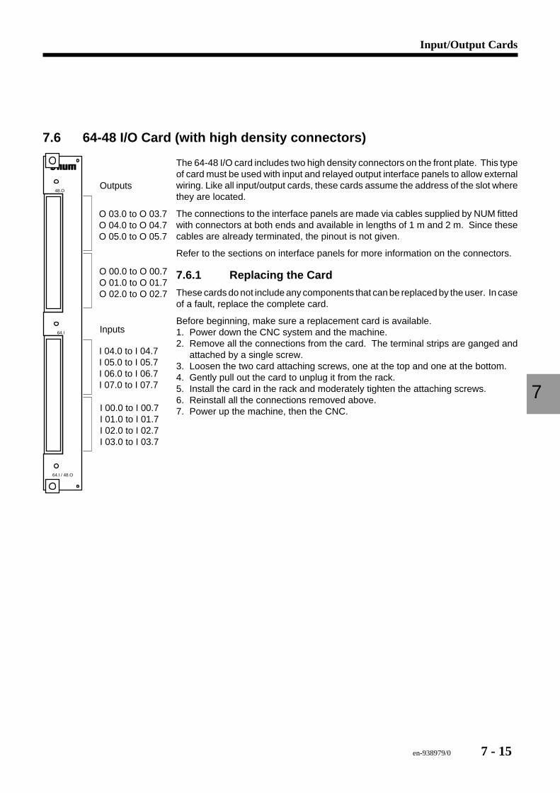
en-938979/0 7 - 15
Input/Output Cards
7
7.6 64-48 I/O Card (with high density connectors)
64.I / 48.O
64.I
48.O
I 00.0 to I 00.7I 01.0 to I 01.7I 02.0 to I 02.7I 03.0 to I 03.7
Inputs
I 04.0 to I 04.7I 05.0 to I 05.7I 06.0 to I 06.7I 07.0 to I 07.7
O 03.0 to O 03.7O 04.0 to O 04.7O 05.0 to O 05.7
Outputs
O 00.0 to O 00.7O 01.0 to O 01.7O 02.0 to O 02.7
The 64-48 I/O card includes two high density connectors on the front plate. This typeof card must be used with input and relayed output interface panels to allow externalwiring. Like all input/output cards, these cards assume the address of the slot wherethey are located.
The connections to the interface panels are made via cables supplied by NUM fittedwith connectors at both ends and available in lengths of 1 m and 2 m. Since thesecables are already terminated, the pinout is not given.
Refer to the sections on interface panels for more information on the connectors.
7.6.1 Replacing the Card
These cards do not include any components that can be replaced by the user. In caseof a fault, replace the complete card.
Before beginning, make sure a replacement card is available.1. Power down the CNC system and the machine.2. Remove all the connections from the card. The terminal strips are ganged and
attached by a single screw.3. Loosen the two card attaching screws, one at the top and one at the bottom.4. Gently pull out the card to unplug it from the rack.5. Install the card in the rack and moderately tighten the attaching screws.6. Reinstall all the connections removed above.7. Power up the machine, then the CNC.
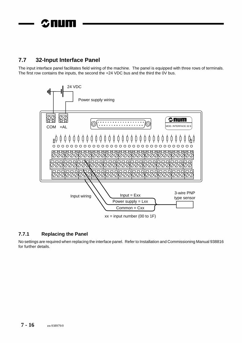
7 - 16 en-938979/0
7.7 32-Input Interface PanelThe input interface panel facilitates field wiring of the machine. The panel is equipped with three rows of terminals.The first row contains the inputs, the second the +24 VDC bus and the third the 0V bus.
MOD. INTERFACE 32 E
E00
E1F
COM +AL
xx = input number (00 to 1F)
Input wiring
Power supply wiring
24 VDC
3-wire PNPtype sensor
Input = Exx
Power supply = Lxx
Common = Cxx
7.7.1 Replacing the Panel
No settings are required when replacing the interface panel. Refer to Installation and Commissioning Manual 938816for further details.
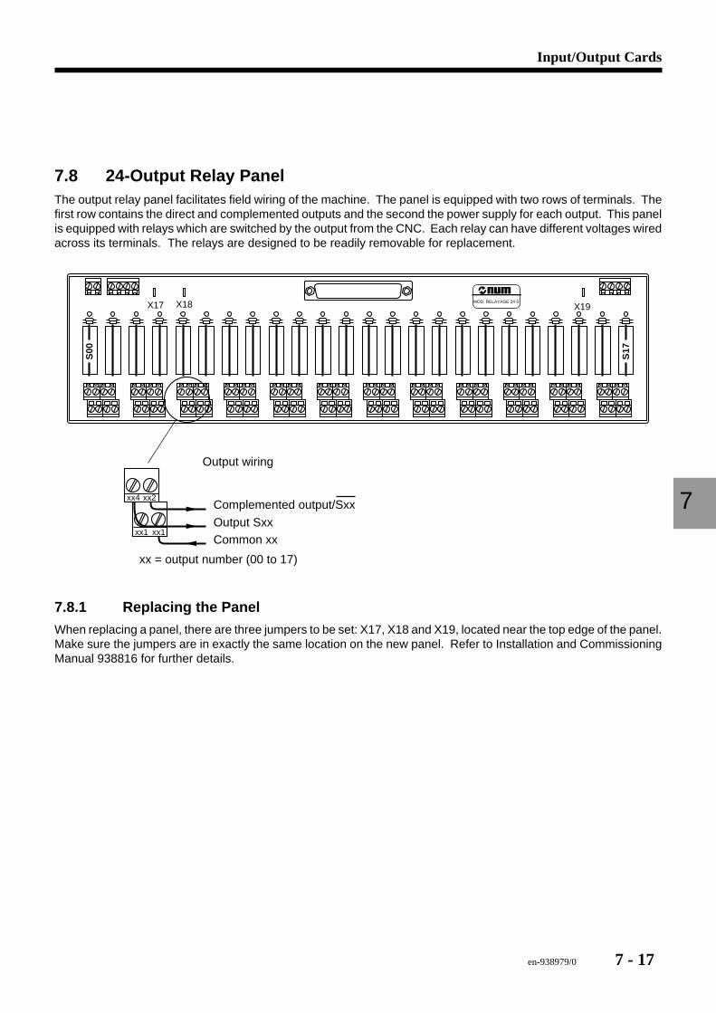
en-938979/0 7 - 17
Input/Output Cards
7
7.8 24-Output Relay PanelThe output relay panel facilitates field wiring of the machine. The panel is equipped with two rows of terminals. Thefirst row contains the direct and complemented outputs and the second the power supply for each output. This panelis equipped with relays which are switched by the output from the CNC. Each relay can have different voltages wiredacross its terminals. The relays are designed to be readily removable for replacement.
MOD. RELAYAGE 24 S
S00
S17
xx4 xx2
xx1 xx1Output Sxx
Complemented output/Sxx
Common xx
xx = output number (00 to 17)
X17 X18 X19
Output wiring
7.8.1 Replacing the Panel
When replacing a panel, there are three jumpers to be set: X17, X18 and X19, located near the top edge of the panel.Make sure the jumpers are in exactly the same location on the new panel. Refer to Installation and CommissioningManual 938816 for further details.

7 - 18 en-938979/0
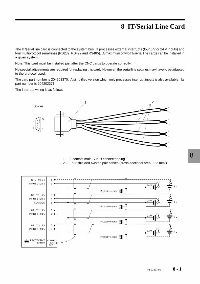
en-938979/0 8 - 1
IT/Serial Line Card
8
8 IT/Serial Line Card
The IT/serial line card is connected to the system bus. It processes external interrupts (four 5 V or 24 V inputs) andfour multiprotocol serial lines (RS232, RS422 and RS485). A maximum of two IT/serial line cards can be installed ina given system.
Note: This card must be installed just after the CNC cards to operate correctly.
No special adjustments are required for replacing this card. However, the serial line settings may have to be adaptedto the protocol used.
The card part number is 204203370. A simplified version which only processes interrupt inputs is also available. Itspart number is 204202371.
The interrupt wiring is as follows
1 2Solder
6
95
1
1 - 9-contact male Sub.D connector plug2 - Four shielded twisted pair cables (cross-sectional area 0,22 mm2)
1INPUT 0 : 5 V
CONNEC-TOR
SHELL
Protective earth
2INPUT 0 : 24 V
3INPUT 1 : 5 V
4INPUT 1 : 24 V
5COMMON
6INPUT 2 : 5 V
7INPUT 2 : 24 V
8INPUT 3 : 5 V
9INPUT 3 : 24 V
PROTECTIVEEARTH
24 V 5 V
24 V 5 V
24 V 5 V
24 V 5 V
Protective earth
Protective earth
Protective earth
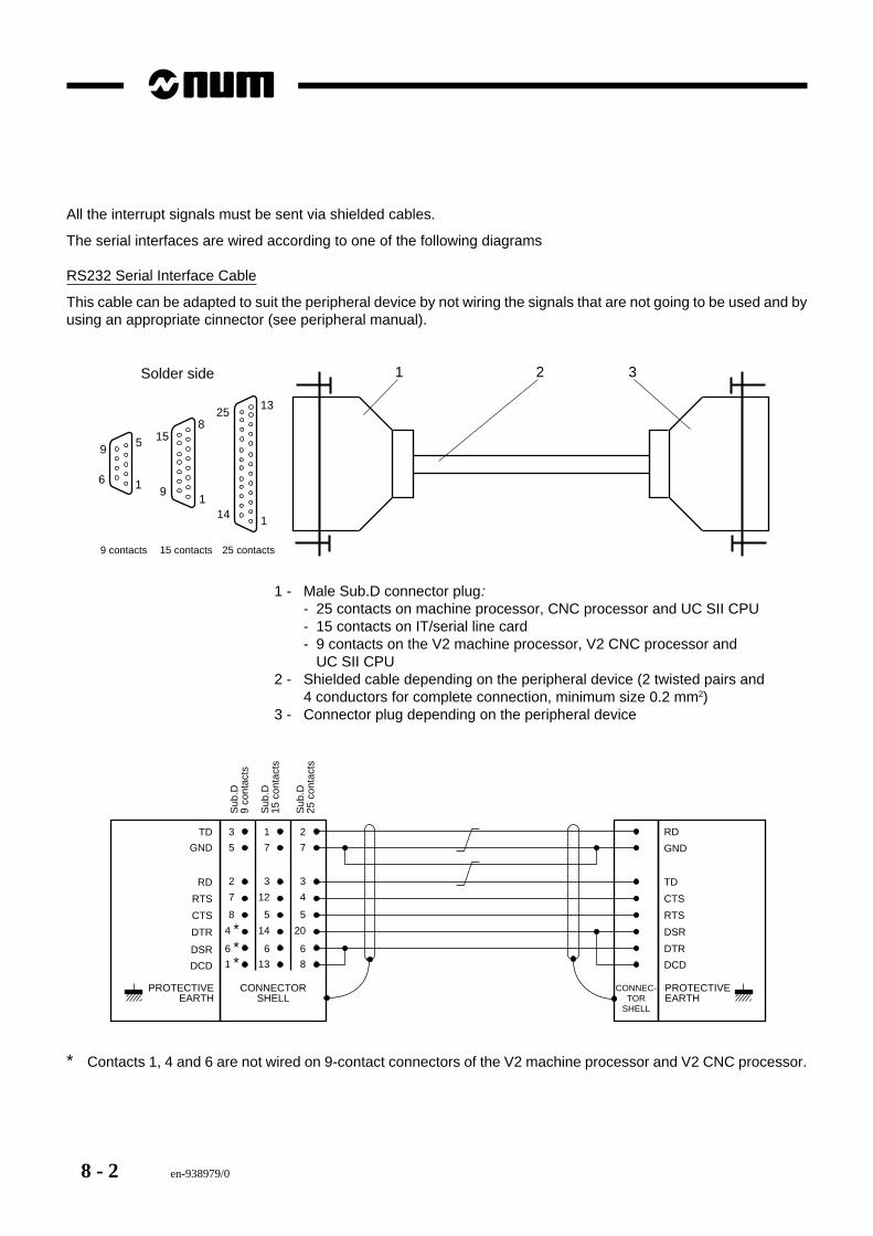
8 - 2 en-938979/0
All the interrupt signals must be sent via shielded cables.
The serial interfaces are wired according to one of the following diagrams
RS232 Serial Interface Cable
This cable can be adapted to suit the peripheral device by not wiring the signals that are not going to be used and byusing an appropriate cinnector (see peripheral manual).
1
13
25 contacts
25
Solder side 1 2 3
8
19
15
15 contacts
14
6
95
1
9 contacts
1 - Male Sub.D connector plug:- 25 contacts on machine processor, CNC processor and UC SII CPU- 15 contacts on IT/serial line card- 9 contacts on the V2 machine processor, V2 CNC processor and
UC SII CPU2 - Shielded cable depending on the peripheral device (2 twisted pairs and
4 conductors for complete connection, minimum size 0.2 mm2)3 - Connector plug depending on the peripheral device
CONNECTORSHELL
TD
RD
RTS
CTS
DTR
PROTECTIVEEARTH
7
2
3
4
5
20
6
8
GND
DSR
DCD
RD
TD
CTS
RTS
DSR
DTR
DCD
GND
CONNEC-TOR
SHELL
PROTECTIVEEARTH
5
3
2
7
8
4 ∗6 ∗1 ∗
7
1
3
12
5
14
6
13
Sub
.D9
cont
acts
Sub
.D25
con
tact
s
Sub
.D15
con
tact
s
∗ Contacts 1, 4 and 6 are not wired on 9-contact connectors of the V2 machine processor and V2 CNC processor.
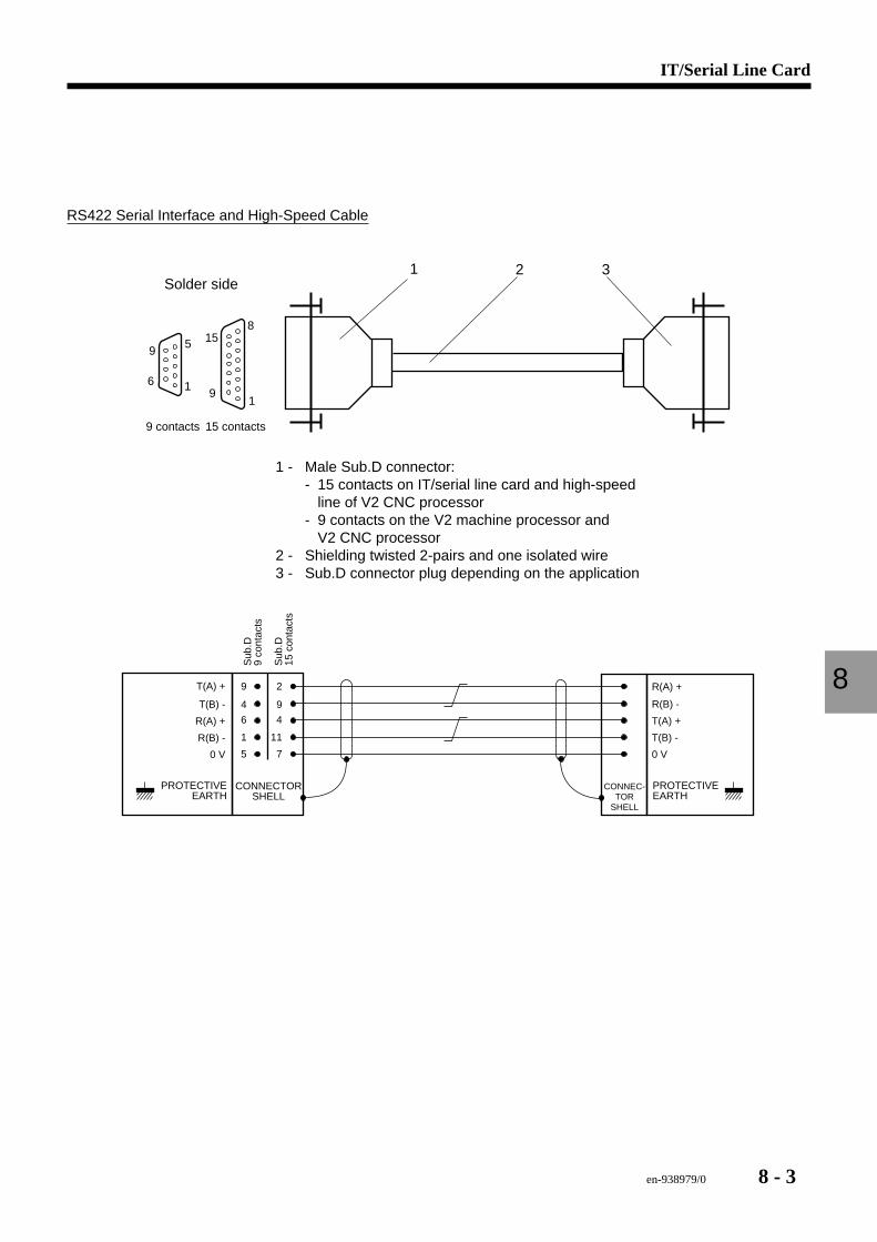
en-938979/0 8 - 3
IT/Serial Line Card
8
RS422 Serial Interface and High-Speed Cable
2 31Solder side
8
19
15
15 contacts
6
95
1
9 contacts
1 - Male Sub.D connector:- 15 contacts on IT/serial line card and high-speed
line of V2 CNC processor- 9 contacts on the V2 machine processor and
V2 CNC processor2 - Shielding twisted 2-pairs and one isolated wire3 - Sub.D connector plug depending on the application
CONNECTORSHELL
T(B) -
R(A) +
R(B) -
PROTECTIVEEARTH
2
9
4
11
R(A) +
R(B) -
T(A) +
T(B) -
T(A) +
CONNEC-TOR
SHELL
PROTECTIVEEARTH
0 V 7 0 V
9
4
6
1
5
Sub
.D9
cont
acts
Sub
.D15
con
tact
s
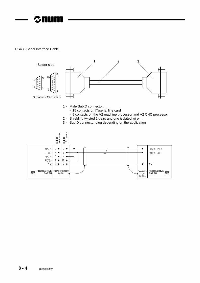
8 - 4 en-938979/0
RS485 Serial Interface Cable
2 31Solder side
8
19
15
15 contacts
6
95
1
9 contacts
1 - Male Sub.D connector:- 15 contacts on IT/serial line card- 9 contacts on the V2 machine processor and V2 CNC processor
2 - Shielding twisted 2-pairs and one isolated wire3 - Sub.D connector plug depending on the application
CONNECTORSHELL
T(B) -
R(A) +
R(B) -
PROTECTIVEEARTH
2
9
4
11
R(A) / T(A) +
R(B) / T(B) -
T(A) +
CONNEC-TOR
SHELL
PROTECTIVEEARTH
0 V 7 0 V
9
4
6
1
5
Sub
.D9
cont
acts
Sub
.D15
con
tact
s
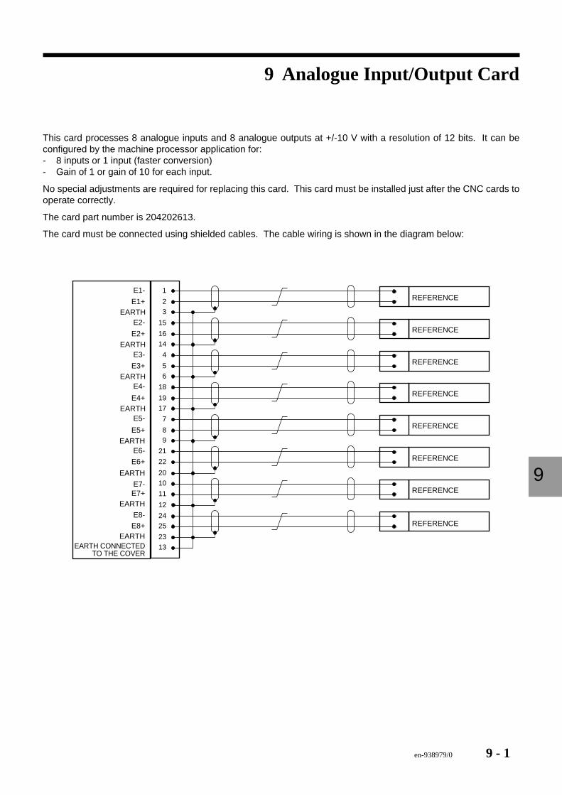
en-938979/0 9 - 1
Analogue Input/Output Card
9
9 Analogue Input/Output Card
This card processes 8 analogue inputs and 8 analogue outputs at +/-10 V with a resolution of 12 bits. It can beconfigured by the machine processor application for:- 8 inputs or 1 input (faster conversion)- Gain of 1 or gain of 10 for each input.
No special adjustments are required for replacing this card. This card must be installed just after the CNC cards tooperate correctly.
The card part number is 204202613.
The card must be connected using shielded cables. The cable wiring is shown in the diagram below:
17EARTH7
89
21
22
20
10
E5-
E5+EARTH
E6-
E6+
EARTH
E7-E7+
EARTH
E8-E8+
EARTHEARTH CONNECTED
TO THE COVER
REFERENCE
6EARTH18
19
E4-
E4+
14EARTH4
5
E3-
E3+
3EARTH15
16
E2-
E2+
1
2
E1-
E1+
11
12
2425
23
13
REFERENCE
REFERENCE
REFERENCE
REFERENCE
REFERENCE
REFERENCE
REFERENCE

9 - 2 en-938979/0
Remote Input/Output Modules
en-938979/0 10 - 1
10.1 Introduction 10 - 310.1.1 General 10 - 310.1.2 Module Connection to the CNC 10 - 4
10.2 Diagnostics and Maintenance 10 - 510.2.1 Block Diagram of a Remote I/O Module 10 - 510.2.2 Power Supply Faults 10 - 610.2.3 Fibre-Optic Ring Fault 10 - 610.2.4 Address Fault 10 - 610.2.5 Input or Output Stage Fault 10 - 6
10.3 Replacement 10 - 710.3.1 Setting the Output Power 10 - 710.3.2 Programming 10 - 810.3.2.1 Module Addressing 10 - 8
10 Remote Input/Output Modules

10 - 2 en-938979/0
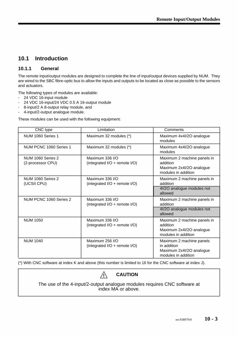
Remote Input/Output Modules
en-938979/0 10 - 3
10.1 Introduction
10.1.1 General
The remote input/output modules are designed to complete the line of input/output devices supplied by NUM. Theyare wired to the SBC fibre-optic bus to allow the inputs and outputs to be located as close as possible to the sensorsand actuators.
The following types of modules are available:- 24 VDC 16-input module- 24 VDC 16-input/24 VDC 0.5 A 16-output module- 8-input/2 A 8-output relay module, and- 4-input/2-output analogue module.
These modules can be used with the following equipment:
CNC type Limitation Comments
NUM 1060 Series 1 Maximum 32 modules (*) Maximum 4x4I/2O analoguemodules
NUM PCNC 1060 Series 1 Maximum 32 modules (*) Maximum 4x4I/2O analoguemodules
NUM 1060 Series 2 Maximum 336 I/O Maximum 2 machine panels in(2-processor CPU) (integrated I/O + remote I/O) addition
Maximum 2x4I/2O analoguemodules in addition
NUM 1060 Seires 2 Maximum 336 I/O Maximum 2 machine panels in(UCSII CPU) (integrated I/O + remote I/O) addition
4I/2O analogue modules notallowed
NUM PCNC 1060 Series 2 Maximum 336 I/O Maximum 2 machine panels in(integrated I/O + remote I/O) addition
4I/2O analogue modules notallowed
NUM 1050 Maximum 336 I/O Maximum 2 machine panels in(integrated I/O + remote I/O) addition
Maximum 2x4I/2O analoguemodules in addition
NUM 1040 Maximum 256 I/O Maximum 2 machine panels(integrated I/O + remote I/O) in addition
Maximum 2x4I/2O analoguemodules in addition
(*) With CNC software at index K and above (this number is limited to 16 for the CNC software at index J).
! CAUTION
The use of the 4-input/2-output analogue modules requires CNC software atindex MA or above.
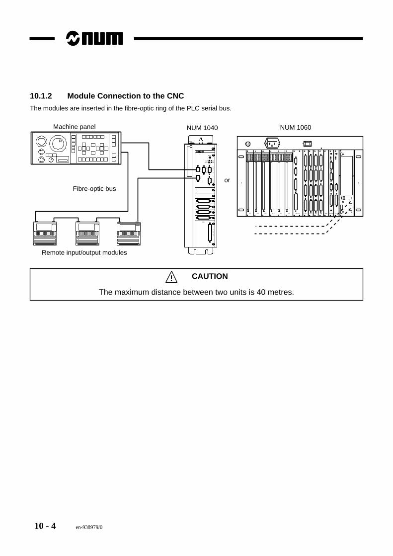
10 - 4 en-938979/0
10.1.2 Module Connection to the CNC
The modules are inserted in the fibre-optic ring of the PLC serial bus.
Axis
Panel
It/Ana
Com
1
Serial
Rec
Em
L1Def
L3Pwr
L2
Fail
Reset
NUM 1040 NUM 1060Machine panel
Remote input/output modules
Fibre-optic bus
AlimProc Mach Proc CNAxesAxesAxes32 E 32 E 32 E 32 S32 S32 S Axes MemProc. PC
or
! CAUTION
The maximum distance between two units is 40 metres.
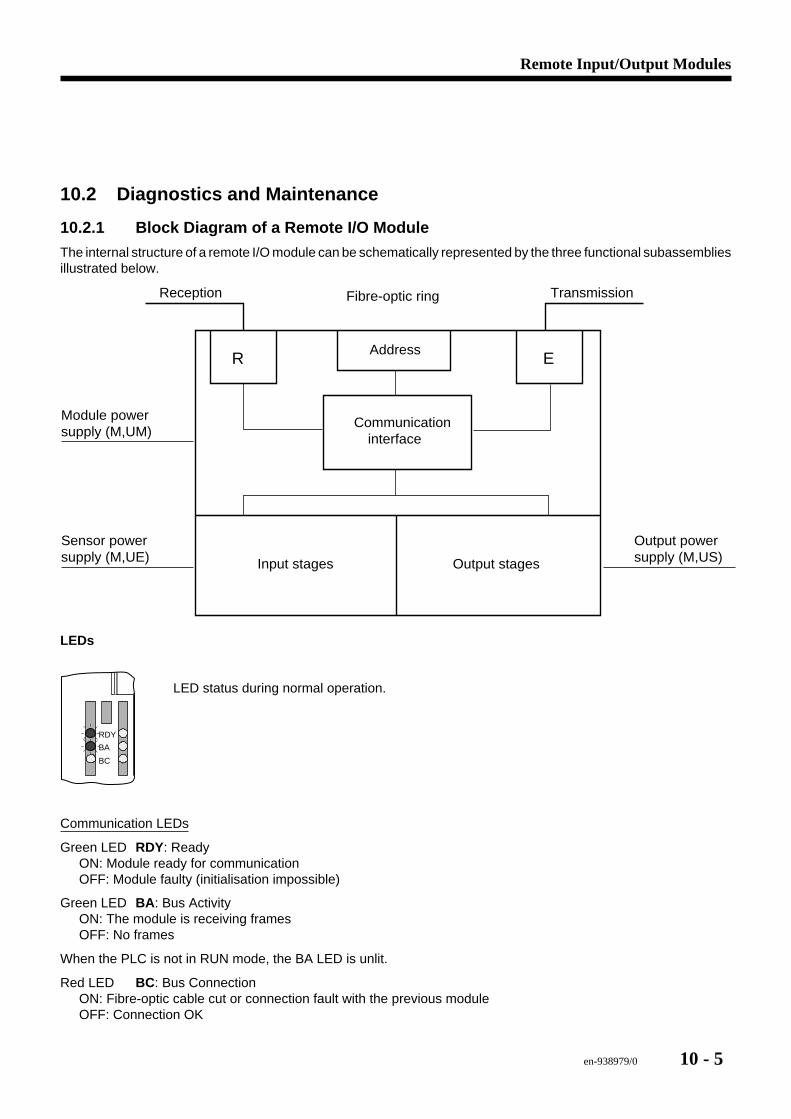
Remote Input/Output Modules
en-938979/0 10 - 5
10.2 Diagnostics and Maintenance
10.2.1 Block Diagram of a Remote I/O Module
The internal structure of a remote I/O module can be schematically represented by the three functional subassembliesillustrated below.
R EAddress
Communicationinterface
Input stages Output stages
Reception TransmissionFibre-optic ring
Module power supply (M,UM)
Sensor power supply (M,UE)
Output power supply (M,US)
LEDs
BA
RDY
BC
LED status during normal operation.
Communication LEDs
Green LED RDY: ReadyON: Module ready for communicationOFF: Module faulty (initialisation impossible)
Green LED BA : Bus ActivityON: The module is receiving framesOFF: No frames
When the PLC is not in RUN mode, the BA LED is unlit.
Red LED BC: Bus ConnectionON: Fibre-optic cable cut or connection fault with the previous moduleOFF: Connection OK

10 - 6 en-938979/0
Faults can be classified in the following categories:- Power supply faults- Fault on the fibre-optic ring- Address fault- Input or output stage fault.
10.2.2 Power Supply FaultsTo operate correctly, a remote I/O module requires presence of 24 VDC power supply for:
- The internal module logic (M,UM)- The sensors wired to the inputs- The output stages.
The presence of each of these power supplies is indicated by a green LED.
Failure of the power supply of a module causes a break in the fibre-optic ring, a watchdog timeout and sets the generallink fault bit (DEFBUS %R97F.0).
Failure of the power supply of the sensors and/or the output stages is not detected or indicated by the PLC. It resultsin malfunctioning of the automatic control system, since the state of the inputs and/or outputs is no longerrepresentative of reality.
REMARK To enhance safety and availability of the automatic control system, it isrecommended to wire these voltages to inputs that can be continuously monitoredby the PLC programme.
10.2.3 Fibre-Optic Ring Fault
A break in the fibre-optic ring causing a loss of data frames is immediately detected by the PLC, causes a watchdogtimeout and sets the general link fault bit (DEFBUS %R97F.0).
The fibre-optic ring continuity fault can be located as follows:- Search for the module on which the red BC LED is lit- On this module, check that:
- The reception fibre-optic cable (marked Rx) is correctly connected- The fibre-optic cable connecting it to the previous module is not damaged.
- On the previous module, check that:- It is correctly supplied- The transmission fibre-optic cable (marked Tx) is correctly connected- The output power setting switches are correctly set.
10.2.4 Address Fault
It is necessary to make sure that the addresses set on the remote I/O module effectively correspond to the addressesof the I/O variables used in the PLC programme.
When two I/O modules have the same address, the general link fault bit (DEFBUS %R97F.0) is set and a watchdogtimeout occurs.
10.2.5 Input or Output Stage Fault
A fault on an input or output stage is not detected and results in malfunctioning of the automatic control system.
On the 16-input/16-output static I/O module, each shorted output is indicated by a red LED and a status word %Irc3C.W(1 bit per group of 8 outputs).
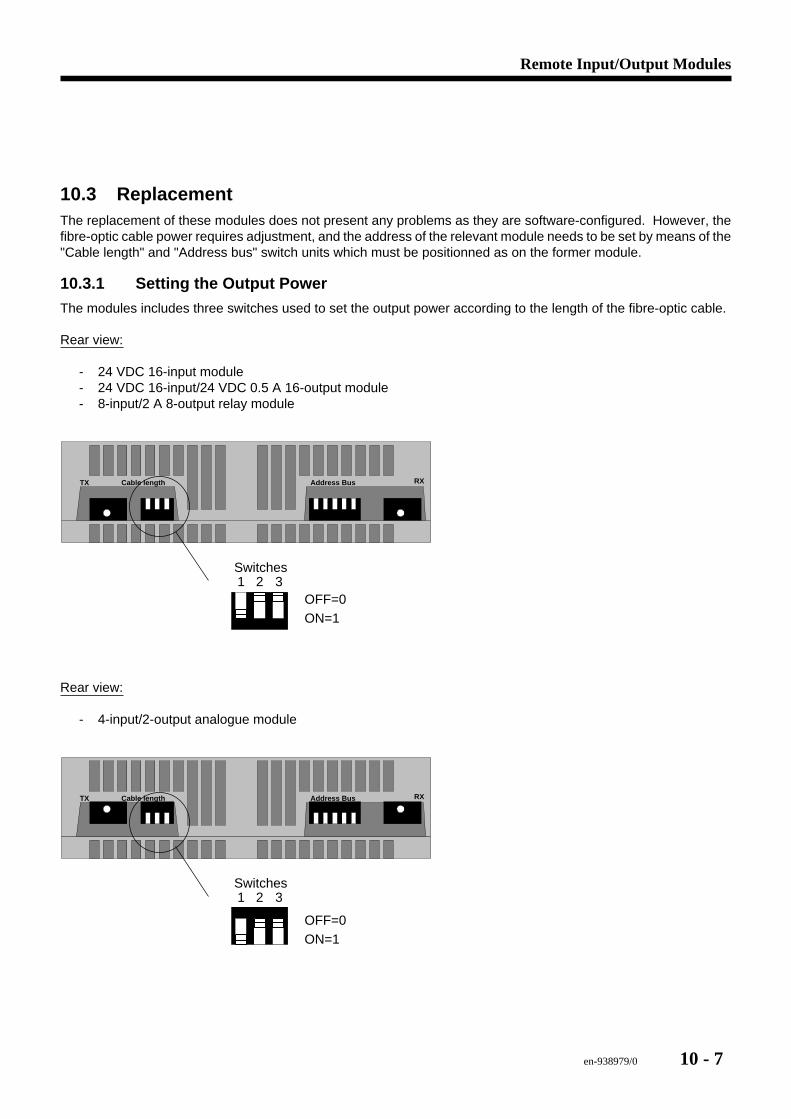
Remote Input/Output Modules
en-938979/0 10 - 7
10.3 ReplacementThe replacement of these modules does not present any problems as they are software-configured. However, thefibre-optic cable power requires adjustment, and the address of the relevant module needs to be set by means of the"Cable length" and "Address bus" switch units which must be positionned as on the former module.
10.3.1 Setting the Output Power
The modules includes three switches used to set the output power according to the length of the fibre-optic cable.
Rear view:
- 24 VDC 16-input module- 24 VDC 16-input/24 VDC 0.5 A 16-output module- 8-input/2 A 8-output relay module
TX RXCable length Address Bus
1 2 3
ON=1OFF=0
Switches
Rear view:
- 4-input/2-output analogue module
TX RXCable length Address Bus
1 2 3
ON=1OFF=0
Switches
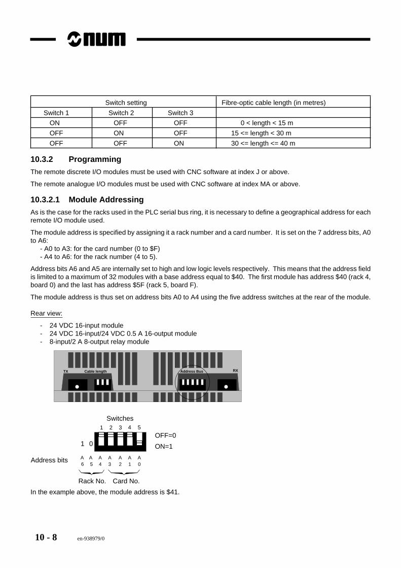
10 - 8 en-938979/0
Switch setting Fibre-optic cable length (in metres)
Switch 1 Switch 2 Switch 3
ON OFF OFF 0 < length < 15 m
OFF ON OFF 15 <= length < 30 m
OFF OFF ON 30 <= length <= 40 m
10.3.2 Programming
The remote discrete I/O modules must be used with CNC software at index J or above.
The remote analogue I/O modules must be used with CNC software at index MA or above.
10.3.2.1 Module Addressing
As is the case for the racks used in the PLC serial bus ring, it is necessary to define a geographical address for eachremote I/O module used.
The module address is specified by assigning it a rack number and a card number. It is set on the 7 address bits, A0to A6:
- A0 to A3: for the card number (0 to $F)- A4 to A6: for the rack number (4 to 5).
Address bits A6 and A5 are internally set to high and low logic levels respectively. This means that the address fieldis limited to a maximum of 32 modules with a base address equal to $40. The first module has address $40 (rack 4,board 0) and the last has address $5F (rack 5, board F).
The module address is thus set on address bits A0 to A4 using the five address switches at the rear of the module.
Rear view:
- 24 VDC 16-input module- 24 VDC 16-input/24 VDC 0.5 A 16-output module- 8-input/2 A 8-output relay module
TX RXCable length Address Bus
4 51 2 3
ON=1
OFF=0
A0
A1
A2
A3
AAA456
Switches
01
Rack No. Card No.
Address bits
In the example above, the module address is $41.
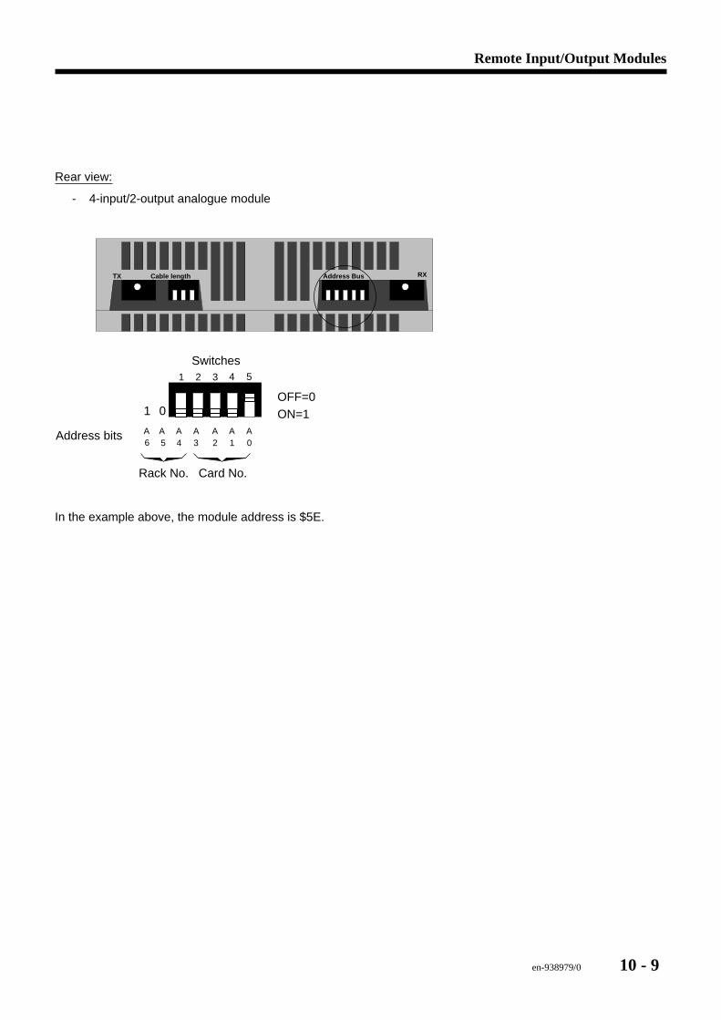
Remote Input/Output Modules
en-938979/0 10 - 9
Rear view:
- 4-input/2-output analogue module
TX RXCable length Address Bus
4 51 2 3
ON=1OFF=0
A0
A1
A2
A3
AAA456
Switches
01
Rack No. Card No.
Address bits
In the example above, the module address is $5E.
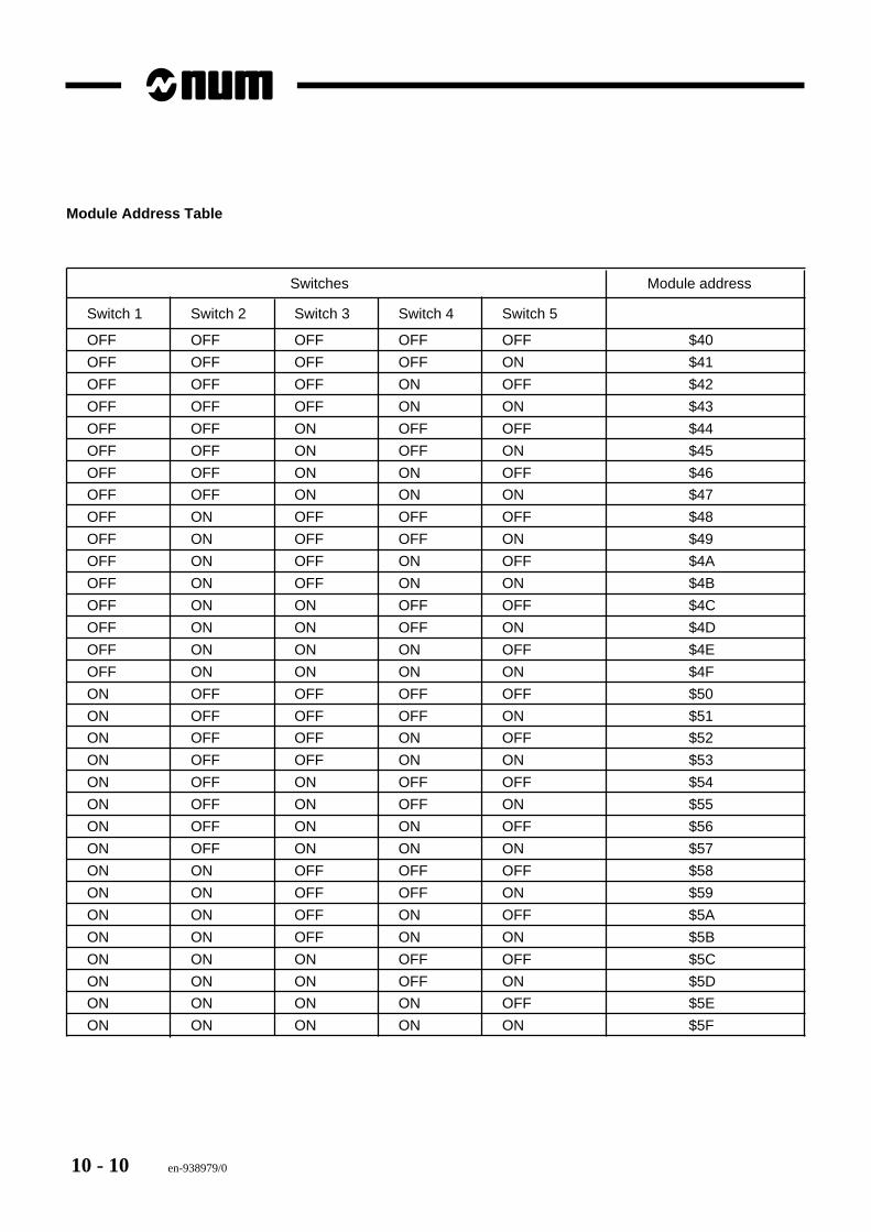
10 - 10 en-938979/0
Module Address Table
Switches Module address
Switch 1 Switch 2 Switch 3 Switch 4 Switch 5
OFF OFF OFF OFF OFF $40
OFF OFF OFF OFF ON $41
OFF OFF OFF ON OFF $42
OFF OFF OFF ON ON $43
OFF OFF ON OFF OFF $44
OFF OFF ON OFF ON $45
OFF OFF ON ON OFF $46
OFF OFF ON ON ON $47
OFF ON OFF OFF OFF $48
OFF ON OFF OFF ON $49
OFF ON OFF ON OFF $4A
OFF ON OFF ON ON $4B
OFF ON ON OFF OFF $4C
OFF ON ON OFF ON $4D
OFF ON ON ON OFF $4E
OFF ON ON ON ON $4F
ON OFF OFF OFF OFF $50
ON OFF OFF OFF ON $51
ON OFF OFF ON OFF $52
ON OFF OFF ON ON $53
ON OFF ON OFF OFF $54
ON OFF ON OFF ON $55
ON OFF ON ON OFF $56
ON OFF ON ON ON $57
ON ON OFF OFF OFF $58
ON ON OFF OFF ON $59
ON ON OFF ON OFF $5A
ON ON OFF ON ON $5B
ON ON ON OFF OFF $5C
ON ON ON OFF ON $5D
ON ON ON ON OFF $5E
ON ON ON ON ON $5F
en-938979/0 11 - 1
Racks
11
11 Racks
11.1 Rack Addressing 11 - 3
11.2 EEPROM Chips 11 - 3
11.3 Temperature Sensor 11 - 3
11.4 Power Connections 11 - 4
11.5 Replacing a Rack 11 - 4

11 - 2 en-938979/0
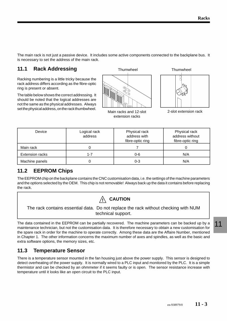
en-938979/0 11 - 3
Racks
11
The main rack is not just a passive device. It includes some active components connected to the backplane bus. Itis necessary to set the address of the main rack.
11.1 Rack Addressing
5
1234
0
Thumwheel Thumwheel
Main racks and 12-slotextension racks
2-slot extension rack
Racking numbering is a little tricky because therack address differs according as the fibre-opticring is present or absent.
The table below shows the correct addressing. Itshould be noted that the logical addresses arenot the same as the physical addresses. Alwaysset the physical address, on the rack thumbwheel.
Device Logical rack Physical rack Physical rackaddress address with address without
fibre-optic ring fibre-optic ring
Main rack 0 7 0
Extension racks 1-7 0-6 N/A
Machine panels 0 0-3 N/A
11.2 EEPROM ChipsThe EEPROM chip on the backplane contains the CNC customisation data, i.e. the settings of the machine parametersand the options selected by the OEM. This chip is not removable! Always back up the data it contains before replacingthe rack.
! CAUTION
The rack contains essential data. Do not replace the rack without checking with NUMtechnical support.
The data contained in the EEPROM can be partially recovered. The machine parameters can be backed up by amaintenance technician, but not the customisation data. It is therefore necessary to obtain a new customisation forthe spare rack in order for the machine to operate correctly. Among these data are the Affaire Number, mentionedin Chapter 1. The other information concerns the maximum number of axes and spindles, as well as the basic andextra software options, the memory sizes, etc.
11.3 Temperature SensorThere is a temperature sensor mounted in the fan housing just above the power supply. This sensor is designed todetect overheating of the power supply. It is normally wired to a PLC input and monitored by the PLC. It is a simplethermistor and can be checked by an ohmmeter if it seems faulty or is open. The sensor resistance increase withtemperature until it looks like an open circuit to the PLC input.

11 - 4 en-938979/0
11.4 Power ConnectionsThe rack is powered by 220 VAC single phase. The power cable is connected to the receptacle located in the upperleft-hand corner of the rack, which is fitted with a small fuse. If the fuse blows, the fans located in the top of the rackare stopped. In case of a problem, the power supply is probably not faulty if the fans are running, but the voltage shouldbe checked. Use a small screwdriver to pry the fuse-holder out of the receptacle. Refer to Section 3.1 for further detailson the power supply.
11.5 Replacing a RackAlways check with NUM technical support before attempting to replace a rack. Also read Section 11.2, EEPROMChips, and back up the machine parameters.
1. Power down the machine and the CNC system2. Unplug all the cables from the cards in the rack and from the rack itself, marking each cable with the name of the
connector it came from!3. Unscrew the rack equipped with all its cards as a single unit.4. Set the old rack next to the new rack on a workbench. Gently remove each card from the old rack and insert it
in the new one, starting with the power supply on the right-hand side and working leftward. Always hold the cardsby the edges and be careful not to touch the surface.
5. Install the new rack in the cabinet.6. Reconnect all the cables disconnected in step 2. Use the marks made when disconnecting the cables to ensure
that each cable is reconnected to the right connector. This is a very critical step!7. Power up the CNC but do not attempt to take the system out of Emergency Stop.8 Follow the procedure for checking or entering a new customisation and restore the machine parameters, referring
to the appropriate sections.9. Once the parameters have been loaded and customisation confirmed, the system is ready to operate.
en-938979/0 12 - 1
Machine Panel
12
12 Machine Panel
12.1 Connections 12 - 312.1.1 Machine Panel Extension 12 - 4
12.2 Fibre-Optic Power Settings 12 - 5
12.3 Address Settings 12 - 5
12.4 Troubleshooting 12 - 6
12.5 Replacing a Machine Panel 12 - 6

12 - 2 en-938979/0
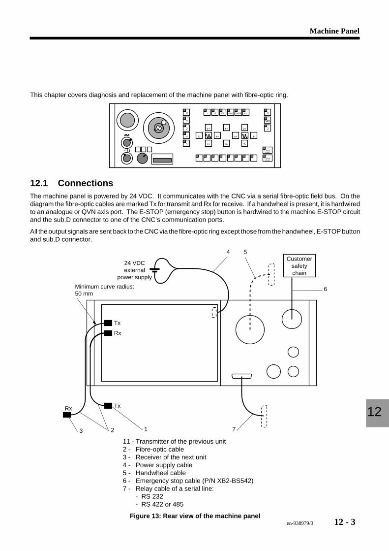
en-938979/0 12 - 3
Machine Panel
12
This chapter covers diagnosis and replacement of the machine panel with fibre-optic ring.
X 1 10 100 1000 10000 ILL
Y
Z
X
M01
Z
4
5
Y+ 5+ Z+
X-
Y- 5- Z-
CYCLESTART
CYCLESTOP
X+ 4+ 4-
12.1 ConnectionsThe machine panel is powered by 24 VDC. It communicates with the CNC via a serial fibre-optic field bus. On thediagram the fibre-optic cables are marked Tx for transmit and Rx for receive. If a handwheel is present, it is hardwiredto an analogue or QVN axis port. The E-STOP (emergency stop) button is hardwired to the machine E-STOP circuitand the sub.D connector to one of the CNC’s communication ports.
All the output signals are sent back to the CNC via the fibre-optic ring except those from the handwheel, E-STOP buttonand sub.D connector.
Rx
Rx
Tx
Tx
6
24 VDCexternal
power supply
Customersafetychain
723
4 5
1
Minimum curve radius: 50 mm
11 - Transmitter of the previous unit2 - Fibre-optic cable3 - Receiver of the next unit4 - Power supply cable5 - Handwheel cable6 - Emergency stop cable (P/N XB2-BS542)7 - Relay cable of a serial line:
- RS 232- RS 422 or 485
Figure 13: Rear view of the machine panel
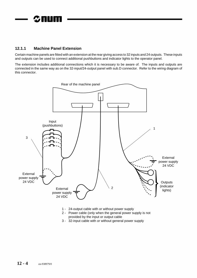
12 - 4 en-938979/0
12.1.1 Machine Panel Extension
Certain machine panels are fitted with an extension at the rear giving access to 32 inputs and 24 outputs. These inputsand outputs can be used to connect additional pushbuttons and indicator lights to the operator panel.
The extension includes additional connections which it is necessary to be aware of. The inputs and outputs areconnected in the same way as on the 32-input/24-output panel with sub.D connector. Refer to the wiring diagram ofthis connector.
Externalpower supply
24 VDC
Outputs(indicator
lights)
Input(pushbuttons)
Externalpower supply
24 VDC
Externalpower supply
24 VDC
3
2
1
Rear of the machine panel
1 - 24-output cable with or without power supply2 - Power cable (only when the general power supply is not
provided by the input or output cable3 - 32-input cable with or without general power supply
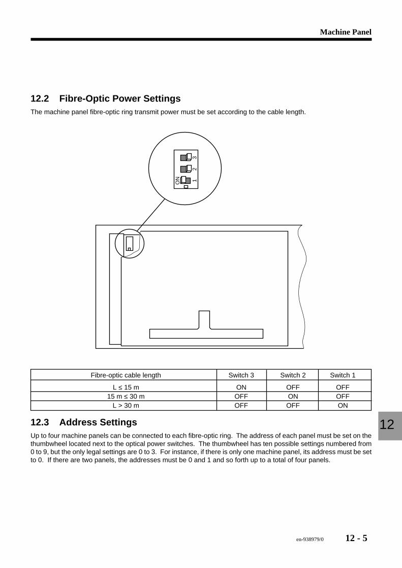
en-938979/0 12 - 5
Machine Panel
12
12.2 Fibre-Optic Power SettingsThe machine panel fibre-optic ring transmit power must be set according to the cable length.
ON 1
23
Fibre-optic cable length Switch 3 Switch 2 Switch 1
L ≤ 15 m ON OFF OFF15 m ≤ 30 m OFF ON OFF
L > 30 m OFF OFF ON
12.3 Address SettingsUp to four machine panels can be connected to each fibre-optic ring. The address of each panel must be set on thethumbwheel located next to the optical power switches. The thumbwheel has ten possible settings numbered from0 to 9, but the only legal settings are 0 to 3. For instance, if there is only one machine panel, its address must be setto 0. If there are two panels, the addresses must be 0 and 1 and so forth up to a total of four panels.
12 - 6 en-938979/0
12.4 TroubleshootingThere is very little troubleshooting to be done on a machine panel. If a panel is thought to be faulty, proceed as shownin the table below.
PROBLEM POSSIBLE CAUSE CORRECTIVE ACTION
An LED or pushbutton is Function inhibited by the PLC Check the PLC variables; refer toinoperative I/O troubleshooting
Pushbutton or LED defective Replace the machine panel
No LEDs or pushbuttons Loss of 24 VDC input power Check the 24 VDC input to theare operative panel
Loss of fibre-optic signals Broken fibre-optic cable, incorrectpower settings or defective panel
Wrong address Check the address set on the panel
12.5 Replacing a Machine PanelProceed as follows to replace the machine panel.
1. Power down the machine and the CNC.2. Disconnect all the cables from the rear of the machine panel. Carefully note down on each fibre-optic cable the
port to which it is connected (sometimes the cables are not marked by the OEM).
REMARK The 24 VDC wires are connected to a special type of terminal rail, without screws.The wires are inserted in holes with special clamping mechanisms. To release aclamp, insert a small screwdriver in the slot directly above where the wire entersthe terminal.
3. Remove the four panel attaching screws and remove the panel.4. Set the removed panel on a workbench next to the replacement panel and check that the power settings on the
two panels are the same.5. Install the new panel and screw down the attaching screws.6. Reconnect all the wires and fibre-optic cables, being careful to connect them correctly, especially the fibre-optic
cables, which it is very easy to connect to the wrong port.7. Power up the machine, then the CNC. Test the new machine panel.
en-938979/0 13 - 1
Software
13
13 Software
13.1 Selecting the CNC Serial Port 13 - 313.1.1 Configuring the Serial Ports 13 - 413.1.2 Configuring the Port for the NUMCOM
Software 13 - 513.1.3 Selecting an Existing Configuration 13 - 5
13.2 CNC Software Backup Methods 13 - 6
13.3 NUMCOM 13 - 813.3.1 Communication Cable 13 - 8
13.4 Part Programme (Zone 0) Backup/Restore 13 - 913.4.1 Backup (Upload) One or
All Programme(s) 13 - 913.4.2 Restore (Download) One or
All Programmes 13 - 10
13.5 Part Programme Backup/Restore in Zone 1, 2 or 3 13 - 1113.5.1 Backup (Upload) a Protected
Memory Zone 13 - 1113.5.2 Restore (Download) a Protected
Memory Area 13 - 12
13.6 Tool Offset Backup/Restore 13 - 1313.6.1 Backup Tool Offsets 13 - 1313.6.2 Restore (Download) Tool Offsets 13 - 13
13.7 Parameter File Backup/Restore 13 - 1413.7.1 Backup (Upload) Parameters 13 - 1413.7.2 Restore (Download) Parameters 13 - 15
13.8 PLC File Backup/Restore 13 - 1613.8.1 Backup (Upload) PLC Files 13 - 1613.8.2 Restore (Download) PLC files 13 - 17
13.9 Axis Calibration File Backup/Restore 13 - 1813.9.1 Backup (Upload) Calibration Data 13 - 1813.9.2 Restore (Download) Calibration Data 13 - 19

13 - 2 en-938979/0
en-938979/0 13 - 3
Software
13
This chapter is devoted to the operation, backup/restore functions and diagnostic tools available to the maintenancepersonnel through NUM software and the MMI.
13.1 Selecting the CNC Serial PortBefore beginning communications, it is necessary to check that the serial line parameters are correctly set for thebackup and restore functions. There are many ways of configuring the serial ports on the NUM 1060 CNCs. The OEMhas a choice of several possible types of connection and configuration schemes. Since the number of possiblecombinations is large, this manual covers only the most common cases. For other cases, contact NUM customersupport or the OEM for assistance.
The table below shows the recommended primary and secondary port choices for each of the three CNC types. If theprimary port is available, select it. Otherwise, choose the secondary port.
PREFERRED SERIAL PORT CHOICESand line (port) numbers
PORT 1060 UCSII 1060 SII 1060 SI
COMM1 Primary(line 0)
COMM2 Secondary(line 1)
SERIE (line 0) (line 0)
RS232C Primary Secondary(line 1) (line 1)
DNC (line 2)
Periph Primary(line 3)
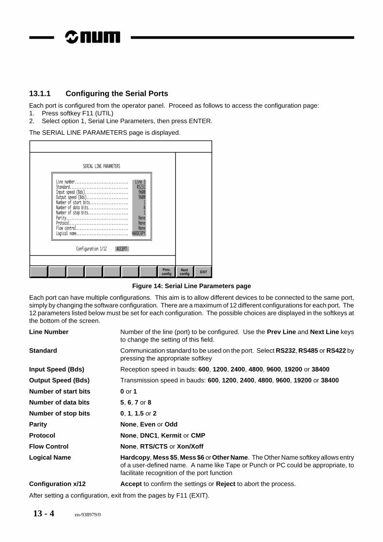
13 - 4 en-938979/0
13.1.1 Configuring the Serial Ports
Each port is configured from the operator panel. Proceed as follows to access the configuration page:1. Press softkey F11 (UTIL)2. Select option 1, Serial Line Parameters, then press ENTER.
The SERIAL LINE PARAMETERS page is displayed.
EXIT Next Prev.config config
SERIAL LINE PARAMETERS
Line number................................ Line 3 Standard................................... RS232 Input speed (Bds).......................... 9600 Output speed (Bds)......................... 9600 Number of start bits....................... 1 Number of data bits........................ 8 Number of stop bits........................ 1 Parity..................................... None Protocol................................... None Flow control............................... None Logical name............................... HARDCOPY
Configuration 1/12 ACCEPT
Figure 14: Serial Line Parameters page
Each port can have multiple configurations. This aim is to allow different devices to be connected to the same port,simply by changing the software configuration. There are a maximum of 12 different configurations for each port. The12 parameters listed below must be set for each configuration. The possible choices are displayed in the softkeys atthe bottom of the screen.
Line Number Number of the line (port) to be configured. Use the Prev Line and Next Line keysto change the setting of this field.
Standard Communication standard to be used on the port. Select RS232, RS485 or RS422 bypressing the appropriate softkey
Input Speed (Bds) Reception speed in bauds: 600, 1200, 2400, 4800, 9600, 19200 or 38400
Output Speed (Bds) Transmission speed in bauds: 600, 1200, 2400, 4800, 9600, 19200 or 38400
Number of start bits 0 or 1
Number of data bits 5 , 6, 7 or 8
Number of stop bits 0 , 1, 1.5 or 2
Parity None , Even or Odd
Protocol None , DNC1, Kermit or CMP
Flow Control None , RTS/CTS or Xon/Xoff
Logical Name Hardcopy , Mess $5 , Mess $6 or Other Name . The Other Name softkey allows entryof a user-defined name. A name like Tape or Punch or PC could be appropriate, tofacilitate recognition of the port function
Configuration x/12 Accept to confirm the settings or Reject to abort the process.
After setting a configuration, exit from the pages by F11 (EXIT).
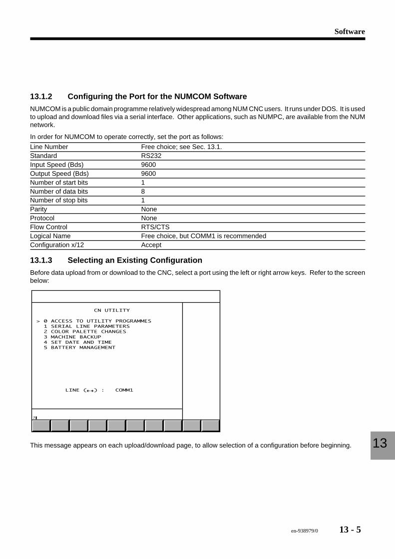
en-938979/0 13 - 5
Software
13
13.1.2 Configuring the Port for the NUMCOM Software
NUMCOM is a public domain programme relatively widespread among NUM CNC users. It runs under DOS. It is usedto upload and download files via a serial interface. Other applications, such as NUMPC, are available from the NUMnetwork.
In order for NUMCOM to operate correctly, set the port as follows:
Line Number Free choice; see Sec. 13.1.Standard RS232Input Speed (Bds) 9600Output Speed (Bds) 9600Number of start bits 1Number of data bits 8Number of stop bits 1Parity NoneProtocol NoneFlow Control RTS/CTSLogical Name Free choice, but COMM1 is recommendedConfiguration x/12 Accept
13.1.3 Selecting an Existing Configuration
Before data upload from or download to the CNC, select a port using the left or right arrow keys. Refer to the screenbelow:
CN UTILITY
> 0 ACCESS TO UTILITY PROGRAMMES 1 SERIAL LINE PARAMETERS 2 COLOR PALETTE CHANGES 3 MACHINE BACKUP 4 SET DATE AND TIME 5 BATTERY MANAGEMENT
LINE ( ) : COMM1
?
This message appears on each upload/download page, to allow selection of a configuration before beginning.
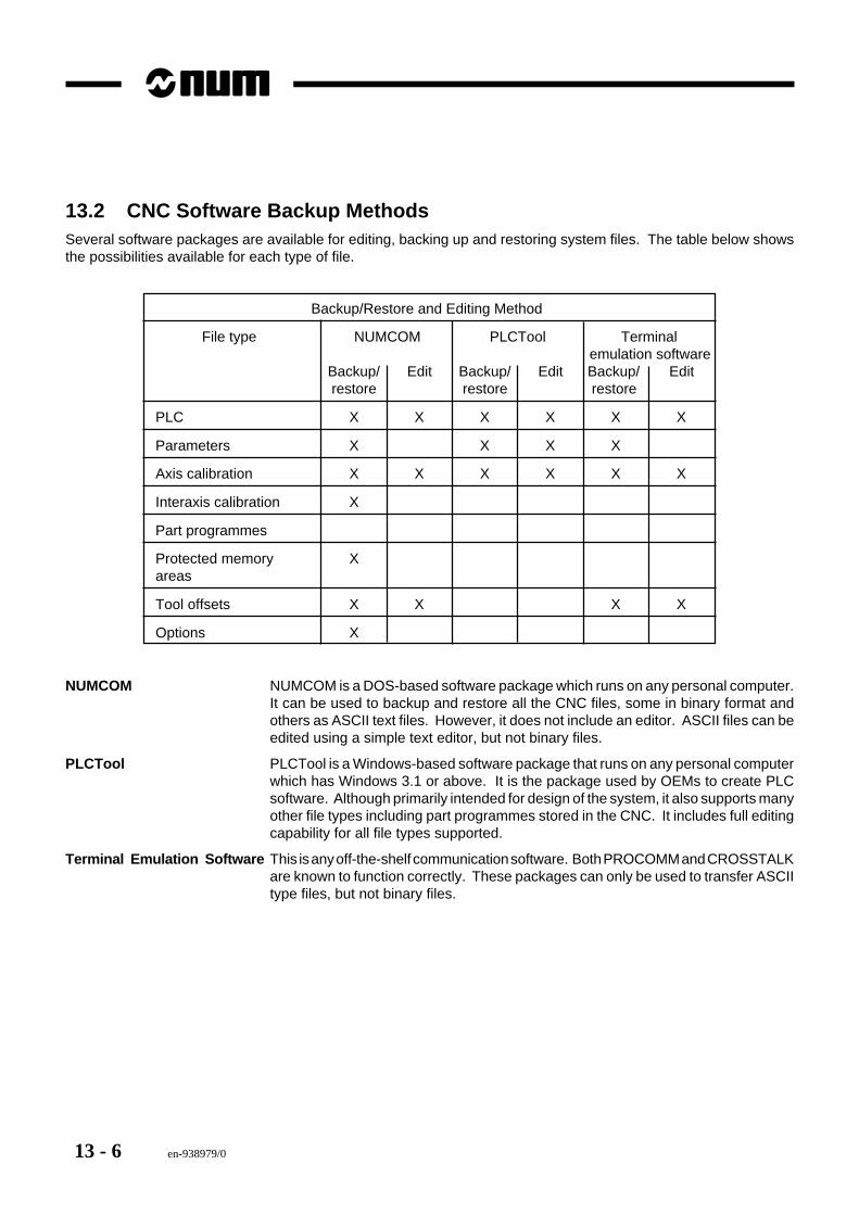
13 - 6 en-938979/0
13.2 CNC Software Backup MethodsSeveral software packages are available for editing, backing up and restoring system files. The table below showsthe possibilities available for each type of file.
Backup/Restore and Editing Method
File type NUMCOM PLCTool Terminalemulation software
Backup/ Edit Backup/ Edit Backup/ Editrestore restore restore
PLC X X X X X X
Parameters X X X X
Axis calibration X X X X X X
Interaxis calibration X
Part programmes
Protected memory Xareas
Tool offsets X X X X
Options X
NUMCOM NUMCOM is a DOS-based software package which runs on any personal computer.It can be used to backup and restore all the CNC files, some in binary format andothers as ASCII text files. However, it does not include an editor. ASCII files can beedited using a simple text editor, but not binary files.
PLCTool PLCTool is a Windows-based software package that runs on any personal computerwhich has Windows 3.1 or above. It is the package used by OEMs to create PLCsoftware. Although primarily intended for design of the system, it also supports manyother file types including part programmes stored in the CNC. It includes full editingcapability for all file types supported.
Terminal Emulation Software This is any off-the-shelf communication software. Both PROCOMM and CROSSTALKare known to function correctly. These packages can only be used to transfer ASCIItype files, but not binary files.
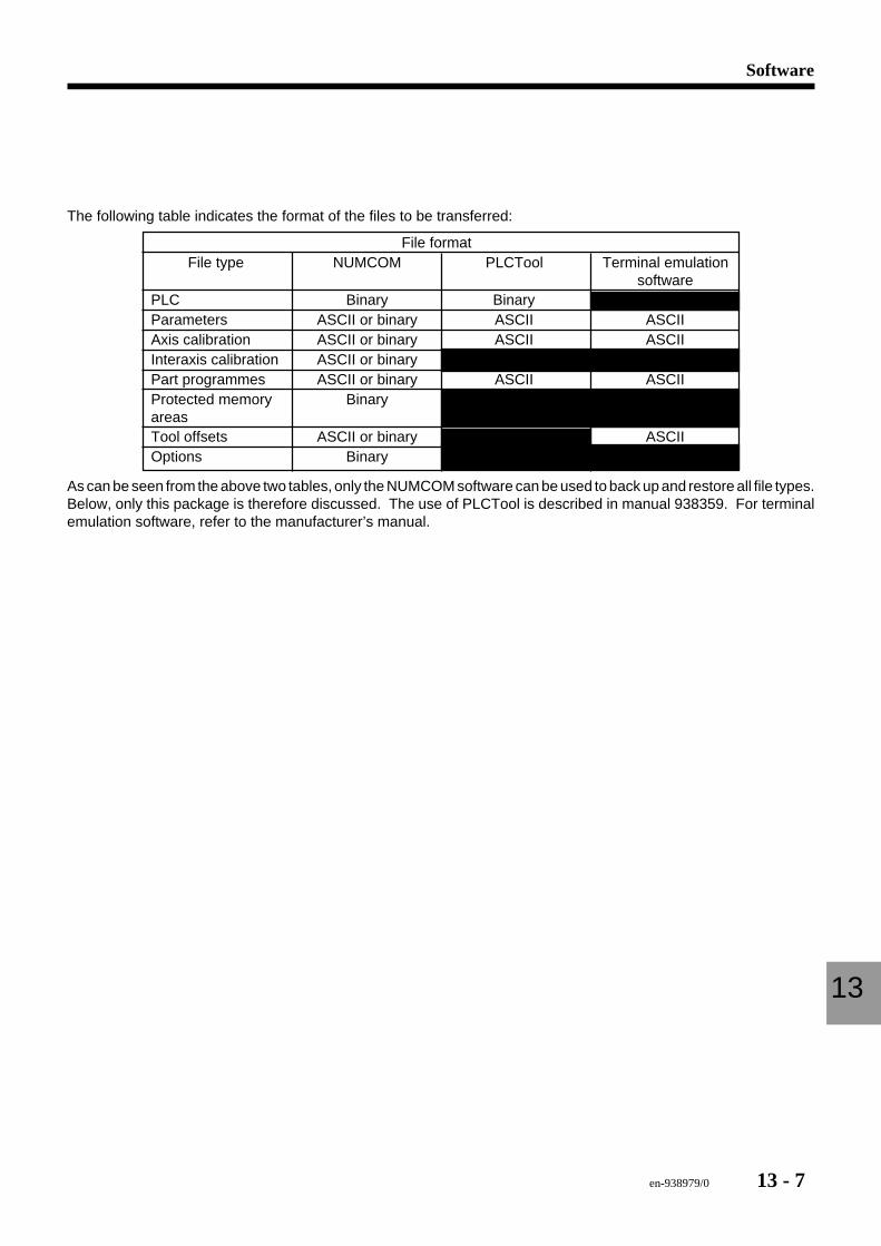
en-938979/0 13 - 7
Software
13
The following table indicates the format of the files to be transferred:
File formatFile type NUMCOM PLCTool Terminal emulation
softwarePLC Binary BinaryParameters ASCII or binary ASCII ASCIIAxis calibration ASCII or binary ASCII ASCIIInteraxis calibration ASCII or binaryPart programmes ASCII or binary ASCII ASCIIProtected memory BinaryareasTool offsets ASCII or binary ASCIIOptions Binary
As can be seen from the above two tables, only the NUMCOM software can be used to back up and restore all file types.Below, only this package is therefore discussed. The use of PLCTool is described in manual 938359. For terminalemulation software, refer to the manufacturer’s manual.
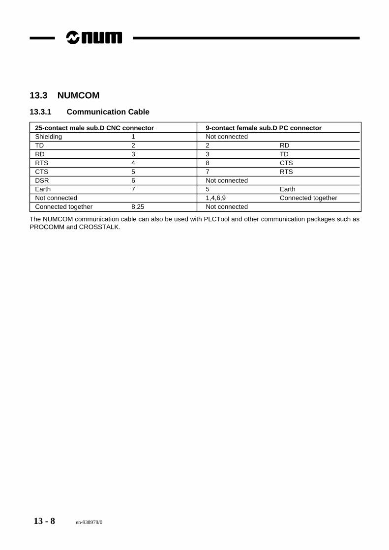
13 - 8 en-938979/0
13.3 NUMCOM
13.3.1 Communication Cable
25-contact male sub.D CNC connector 9-contact female sub.D PC connectorShielding 1 Not connectedTD 2 2 RDRD 3 3 TDRTS 4 8 CTSCTS 5 7 RTSDSR 6 Not connectedEarth 7 5 EarthNot connected 1,4,6,9 Connected togetherConnected together 8,25 Not connected
The NUMCOM communication cable can also be used with PLCTool and other communication packages such asPROCOMM and CROSSTALK.
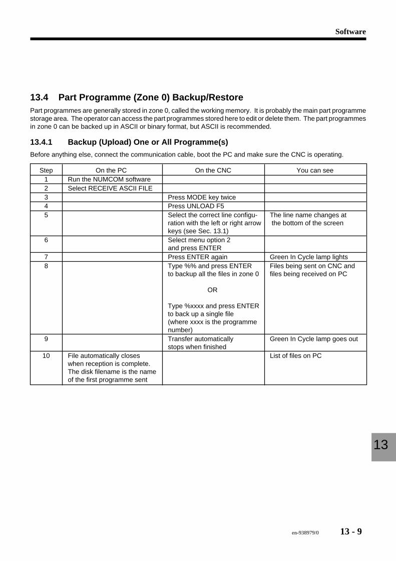
en-938979/0 13 - 9
Software
13
13.4 Part Programme (Zone 0) Backup/RestorePart programmes are generally stored in zone 0, called the working memory. It is probably the main part programmestorage area. The operator can access the part programmes stored here to edit or delete them. The part programmesin zone 0 can be backed up in ASCII or binary format, but ASCII is recommended.
13.4.1 Backup (Upload) One or All Programme(s)
Before anything else, connect the communication cable, boot the PC and make sure the CNC is operating.
Step On the PC On the CNC You can see1 Run the NUMCOM software2 Select RECEIVE ASCII FILE3 Press MODE key twice4 Press UNLOAD F55 Select the correct line configu- The line name changes at
ration with the left or right arrow the bottom of the screenkeys (see Sec. 13.1)
6 Select menu option 2and press ENTER
7 Press ENTER again Green In Cycle lamp lights8 Type %% and press ENTER Files being sent on CNC and
to backup all the files in zone 0 files being received on PC
OR
Type %xxxx and press ENTERto back up a single file(where xxxx is the programmenumber)
9 Transfer automatically Green In Cycle lamp goes outstops when finished
10 File automatically closes List of files on PCwhen reception is complete.The disk filename is the nameof the first programme sent
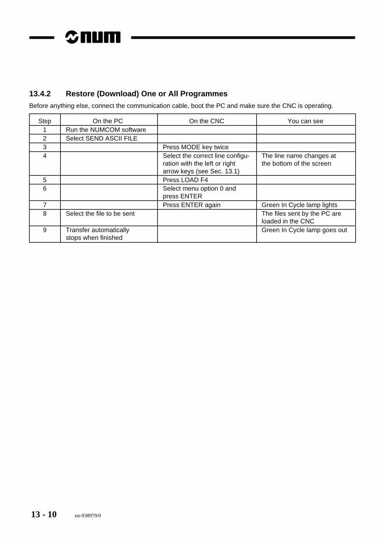
13 - 10 en-938979/0
13.4.2 Restore (Download) One or All Programmes
Before anything else, connect the communication cable, boot the PC and make sure the CNC is operating.
Step On the PC On the CNC You can see1 Run the NUMCOM software2 Select SEND ASCII FILE3 Press MODE key twice4 Select the correct line configu- The line name changes at
ration with the left or right the bottom of the screenarrow keys (see Sec. 13.1)
5 Press LOAD F46 Select menu option 0 and
press ENTER7 Press ENTER again Green In Cycle lamp lights8 Select the file to be sent The files sent by the PC are
loaded in the CNC9 Transfer automatically Green In Cycle lamp goes out
stops when finished
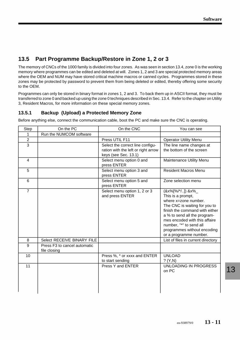
en-938979/0 13 - 11
Software
13
13.5 Part Programme Backup/Restore in Zone 1, 2 or 3The memory of CNCs of the 1000 family is divided into four zones. As was seen in section 13.4, zone 0 is the workingmemory where programmes can be edited and deleted at will. Zones 1, 2 and 3 are special protected memory areaswhere the OEM and NUM may have stored critical machine macros or canned cycles. Programmes stored in thesezones may be protected by password to prevent them from being deleted or edited, thereby offering some securityto the OEM.
Programmes can only be stored in binary format in zones 1, 2 and 3. To back them up in ASCII format, they must betransferred to zone 0 and backed up using the zone 0 techniques described in Sec. 13.4. Refer to the chapter on Utility3, Resident Macros, for more information on these special memory zones.
13.5.1 Backup (Upload) a Protected Memory ZoneBefore anything else, connect the communication cable, boot the PC and make sure the CNC is operating.
Step On the PC On the CNC You can see1 Run the NUMCOM software2 Press UTIL F11 Operator Utility Menu3 Select the correct line configu- The line name changes at
ration with the left or right arrow the bottom of the screenkeys (see Sec. 13.1)
4 Select menu option 0 and Maintenance Utility Menupress ENTER
5 Select menu option 3 and Resident Macros Menupress ENTER
6 Select menu option 5 and Zone selection menupress ENTER
7 Select menu option 1, 2 or 3 (&x%[%/*/..]) &x%_and press ENTER This is a prompt,
where x=zone number.The CNC is waiting for you tofinish the command with eithera % to send all the program-mes encoded with this affairenumber, "*" to send allprogrammes without encodingor a programme number.
8 Select RECEIVE BINARY FILE List of files in current directory9 Press F3 to cancel automatic
file closing10 Press %, * or xxxx and ENTER UNLOAD
to start sending ? (Y,N)11 Press Y and ENTER UNLOADING IN PROGRESS
on PC
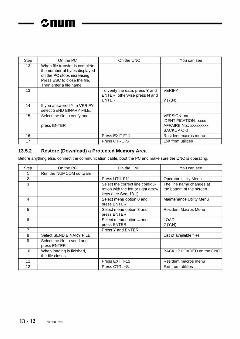
13 - 12 en-938979/0
Step On the PC On the CNC You can see12 When file transfer is complete,
the number of bytes displayedon the PC stops increasing.Press ESC to close the file.Then enter a file name.
13 To verify the data, press Y and VERIFYENTER; otherwise press N andENTER ? (Y,N)
14 If you answered Y to VERIFY,select SEND BINARY FILE.
15 Select the file to verify and VERSION: xxIDENTIFICATION: xxxx
press ENTER AFFAIRE No.: xxxxxxxxxBACKUP OK!
16 Press EXIT F11 Resident macros menu17 Press CTRL+S Exit from utilities
13.5.2 Restore (Download) a Protected Memory Area
Before anything else, connect the communication cable, boot the PC and make sure the CNC is operating.
Step On the PC On the CNC You can see1 Run the NUMCOM software2 Press UTIL F11 Operator Utility Menu3 Select the correct line configu- The line name changes at
ration with the left or right arrow the bottom of the screenkeys (see Sec. 13.1)
4 Select menu option 0 and Maintenance Utility Menupress ENTER
5 Select menu option 3 and Resident Macros Menupress ENTER
6 Select menu option 4 and LOADpress ENTER ? (Y,N)
7 Press Y and ENTER8 Select SEND BINARY FILE List of available files9 Select the file to send and
press ENTER10 When loading is finished, BACKUP LOADED on the CNC
the file closes11 Press EXIT F11 Resident macros menu12 Press CTRL+S Exit from utilities
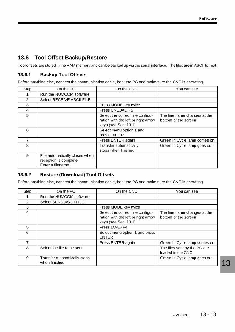
en-938979/0 13 - 13
Software
13
13.6 Tool Offset Backup/RestoreTool offsets are stored in the RAM memory and can be backed up via the serial interface. The files are in ASCII format.
13.6.1 Backup Tool Offsets
Before anything else, connect the communication cable, boot the PC and make sure the CNC is operating.
Step On the PC On the CNC You can see1 Run the NUMCOM software2 Select RECEIVE ASCII FILE3 Press MODE key twice4 Press UNLOAD F55 Select the correct line configu- The line name changes at the
ration with the left or right arrow bottom of the screenkeys (see Sec. 13.1)
6 Select menu option 1 andpress ENTER
7 Press ENTER again Green In Cycle lamp comes on8 Transfer automatically Green In Cycle lamp goes out
stops when finished9 File automatically closes when
reception is complete.Enter a filename.
13.6.2 Restore (Download) Tool OffsetsBefore anything else, connect the communication cable, boot the PC and make sure the CNC is operating.
Step On the PC On the CNC You can see1 Run the NUMCOM software2 Select SEND ASCII FILE3 Press MODE key twice4 Select the correct line configu- The line name changes at the
ration with the left or right arrow bottom of the screenkeys (see Sec. 13.1)
5 Press LOAD F46 Select menu option 1 and press
ENTER7 Press ENTER again Green In Cycle lamp comes on8 Select the file to be sent The files sent by the PC are
loaded in the CNC9 Transfer automatically stops Green In Cycle lamp goes out
when finished
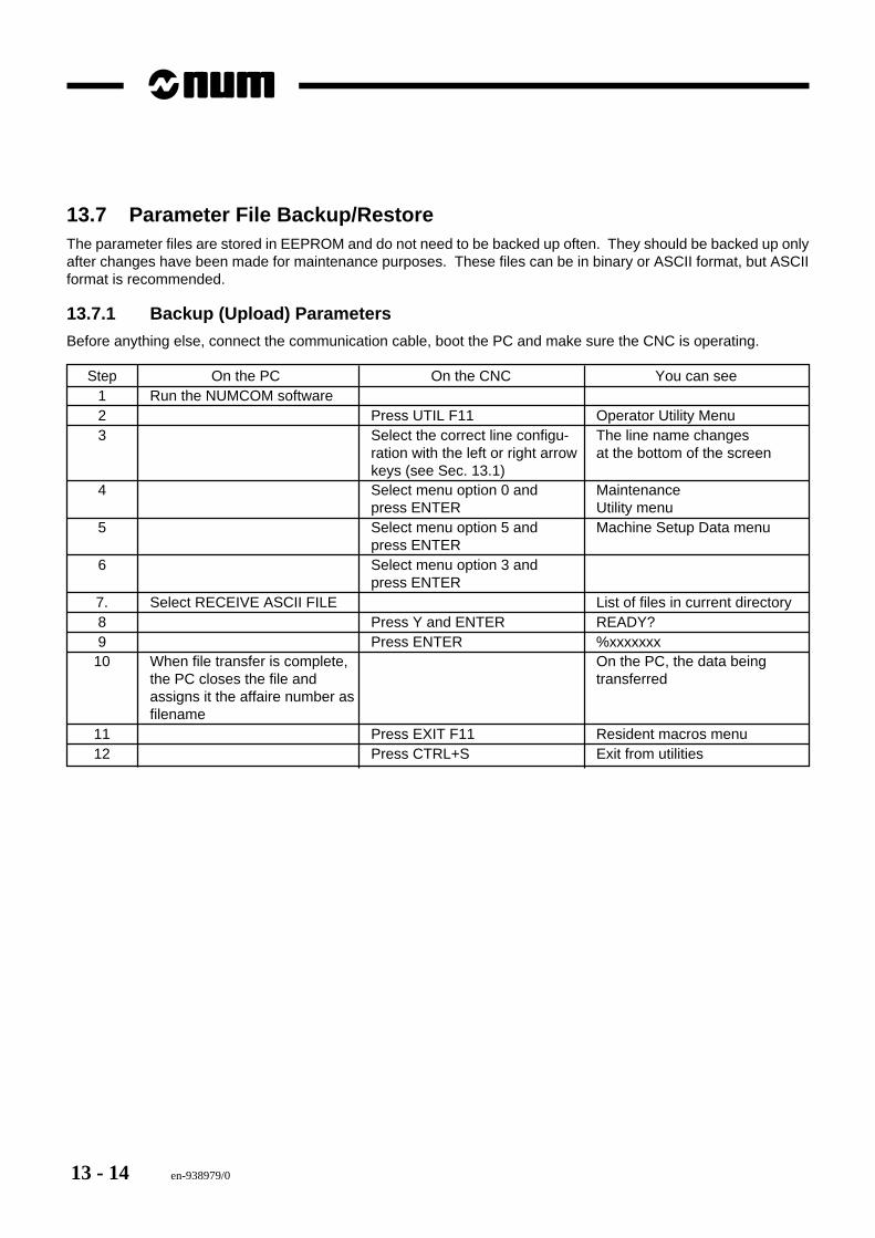
13 - 14 en-938979/0
13.7 Parameter File Backup/RestoreThe parameter files are stored in EEPROM and do not need to be backed up often. They should be backed up onlyafter changes have been made for maintenance purposes. These files can be in binary or ASCII format, but ASCIIformat is recommended.
13.7.1 Backup (Upload) Parameters
Before anything else, connect the communication cable, boot the PC and make sure the CNC is operating.
Step On the PC On the CNC You can see1 Run the NUMCOM software2 Press UTIL F11 Operator Utility Menu3 Select the correct line configu- The line name changes
ration with the left or right arrow at the bottom of the screenkeys (see Sec. 13.1)
4 Select menu option 0 and Maintenancepress ENTER Utility menu
5 Select menu option 5 and Machine Setup Data menupress ENTER
6 Select menu option 3 andpress ENTER
7. Select RECEIVE ASCII FILE List of files in current directory8 Press Y and ENTER READY?9 Press ENTER %xxxxxxx
10 When file transfer is complete, On the PC, the data beingthe PC closes the file and transferredassigns it the affaire number asfilename
11 Press EXIT F11 Resident macros menu12 Press CTRL+S Exit from utilities
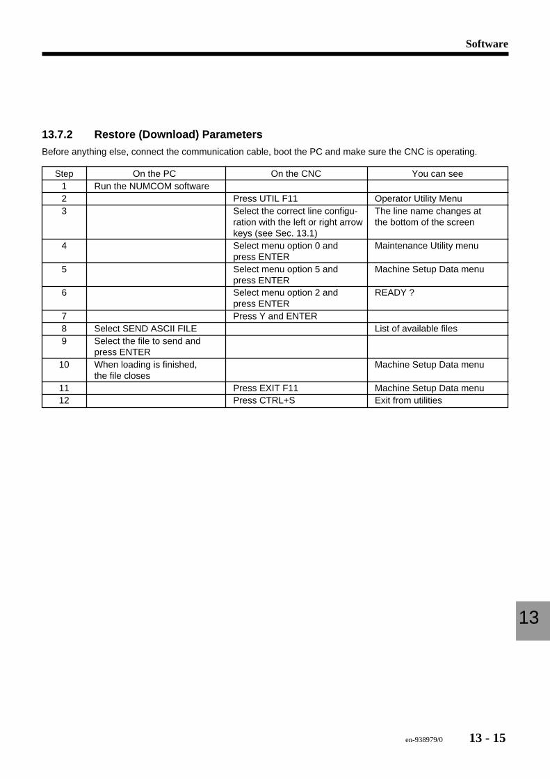
en-938979/0 13 - 15
Software
13
13.7.2 Restore (Download) Parameters
Before anything else, connect the communication cable, boot the PC and make sure the CNC is operating.
Step On the PC On the CNC You can see1 Run the NUMCOM software2 Press UTIL F11 Operator Utility Menu3 Select the correct line configu- The line name changes at
ration with the left or right arrow the bottom of the screenkeys (see Sec. 13.1)
4 Select menu option 0 and Maintenance Utility menupress ENTER
5 Select menu option 5 and Machine Setup Data menupress ENTER
6 Select menu option 2 and READY ?press ENTER
7 Press Y and ENTER8 Select SEND ASCII FILE List of available files9 Select the file to send and
press ENTER10 When loading is finished, Machine Setup Data menu
the file closes11 Press EXIT F11 Machine Setup Data menu12 Press CTRL+S Exit from utilities
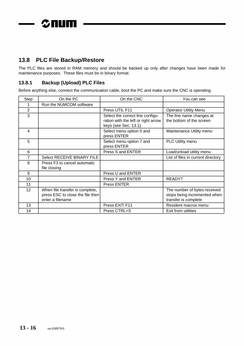
13 - 16 en-938979/0
13.8 PLC File Backup/RestoreThe PLC files are stored in RAM memory and should be backed up only after changes have been made formaintenance purposes. These files must be in binary format.
13.8.1 Backup (Upload) PLC Files
Before anything else, connect the communication cable, boot the PC and make sure the CNC is operating.
Step On the PC On the CNC You can see1 Run the NUMCOM software2 Press UTIL F11 Operator Utility Menu3 Select the correct line configu- The line name changes at
ration with the left or right arrow the bottom of the screenkeys (see Sec. 13.1)
4 Select menu option 0 and Maintenance Utility menupress ENTER
5 Select menu option 7 and PLC Utility menupress ENTER
6 Press S and ENTER Load/unload utility menu7 Select RECEIVE BINARY FILE List of files in current directory8 Press F3 to cancel automatic
file closing9 Press U and ENTER
10 Press Y and ENTER READY?11 Press ENTER12 When file transfer is complete, The number of bytes received
press ESC to close the file then stops being incremented whenenter a filename transfer is complete
13 Press EXIT F11 Resident macros menu14 Press CTRL+S Exit from utilities
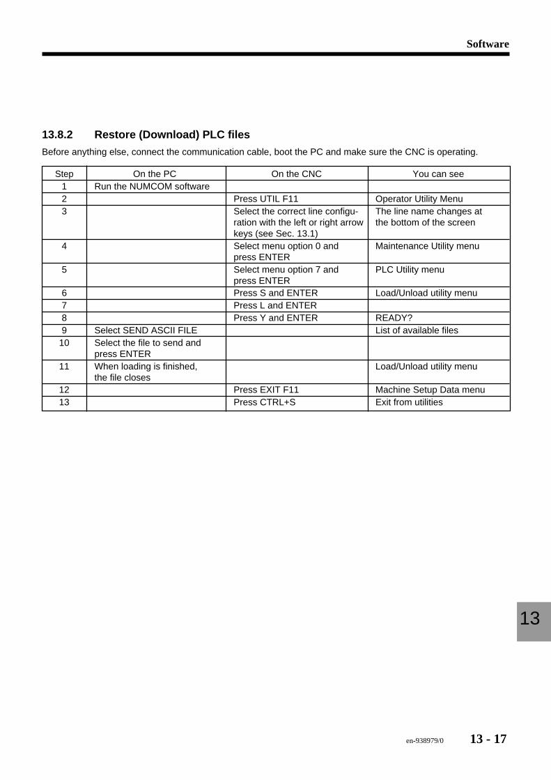
en-938979/0 13 - 17
Software
13
13.8.2 Restore (Download) PLC files
Before anything else, connect the communication cable, boot the PC and make sure the CNC is operating.
Step On the PC On the CNC You can see1 Run the NUMCOM software2 Press UTIL F11 Operator Utility Menu3 Select the correct line configu- The line name changes at
ration with the left or right arrow the bottom of the screenkeys (see Sec. 13.1)
4 Select menu option 0 and Maintenance Utility menupress ENTER
5 Select menu option 7 and PLC Utility menupress ENTER
6 Press S and ENTER Load/Unload utility menu7 Press L and ENTER8 Press Y and ENTER READY?9 Select SEND ASCII FILE List of available files
10 Select the file to send andpress ENTER
11 When loading is finished, Load/Unload utility menuthe file closes
12 Press EXIT F11 Machine Setup Data menu13 Press CTRL+S Exit from utilities
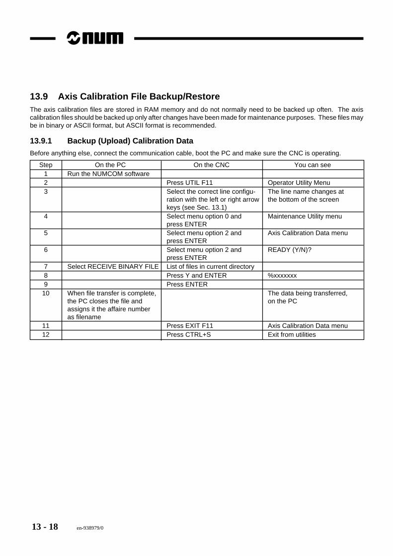
13 - 18 en-938979/0
13.9 Axis Calibration File Backup/RestoreThe axis calibration files are stored in RAM memory and do not normally need to be backed up often. The axiscalibration files should be backed up only after changes have been made for maintenance purposes. These files maybe in binary or ASCII format, but ASCII format is recommended.
13.9.1 Backup (Upload) Calibration Data
Before anything else, connect the communication cable, boot the PC and make sure the CNC is operating.
Step On the PC On the CNC You can see1 Run the NUMCOM software2 Press UTIL F11 Operator Utility Menu3 Select the correct line configu- The line name changes at
ration with the left or right arrow the bottom of the screenkeys (see Sec. 13.1)
4 Select menu option 0 and Maintenance Utility menupress ENTER
5 Select menu option 2 and Axis Calibration Data menupress ENTER
6 Select menu option 2 and READY (Y/N)?press ENTER
7 Select RECEIVE BINARY FILE List of files in current directory8 Press Y and ENTER %xxxxxxx9 Press ENTER
10 When file transfer is complete, The data being transferred,the PC closes the file and on the PCassigns it the affaire numberas filename
11 Press EXIT F11 Axis Calibration Data menu12 Press CTRL+S Exit from utilities
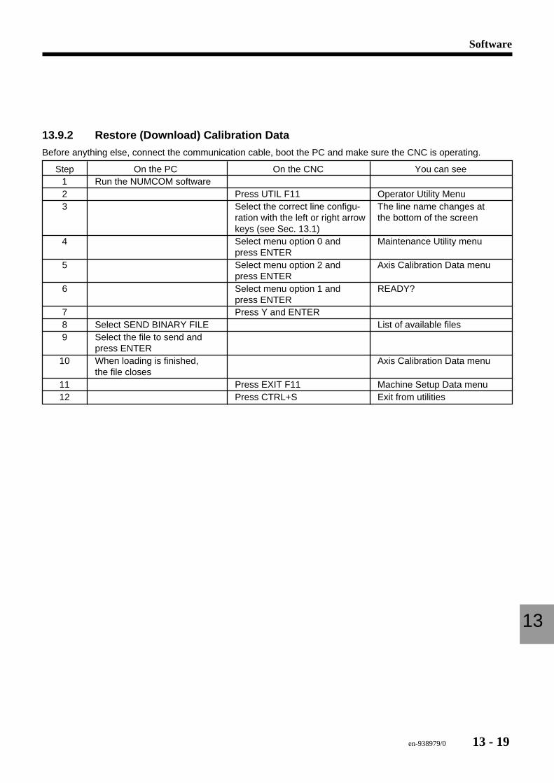
en-938979/0 13 - 19
Software
13
13.9.2 Restore (Download) Calibration Data
Before anything else, connect the communication cable, boot the PC and make sure the CNC is operating.
Step On the PC On the CNC You can see1 Run the NUMCOM software2 Press UTIL F11 Operator Utility Menu3 Select the correct line configu- The line name changes at
ration with the left or right arrow the bottom of the screenkeys (see Sec. 13.1)
4 Select menu option 0 and Maintenance Utility menupress ENTER
5 Select menu option 2 and Axis Calibration Data menupress ENTER
6 Select menu option 1 and READY?press ENTER
7 Press Y and ENTER8 Select SEND BINARY FILE List of available files9 Select the file to send and
press ENTER10 When loading is finished, Axis Calibration Data menu
the file closes11 Press EXIT F11 Machine Setup Data menu12 Press CTRL+S Exit from utilities

13 - 20 en-938979/0
en-938979/0 14 - 1
PLC Diagnostics
14
14 PLC Diagnostics
14.1 Global Addresses CNC —> PLC 14 - 3
14.2 Global Addresses PLC —> CNC 14 - 9
14.3 CNC —> PLC Axis Group Addresses 14 - 18
14.4 PLC —> CNC Axis Group Addresses 14 - 22
14.5 Standard Internal Variables 14 - 24
14.6 Displaying the PLC Variables 14 - 2514.6.1 Displaying PLC Internal or I/O Variables 14 - 2514.6.2 Displaying the Ladder Programme 14 - 26
14.7 Utility 7 - Ladder Programming 14 - 2814.7.1 PLC Operation 14 - 2914.7.2 Monitor and %TS Time Profile 14 - 3214.7.3 PLC File Management 14 - 3314.7.4 I/O Configuration 14 - 3414.7.5 Software Backup 14 - 35

14 - 2 en-938979/0
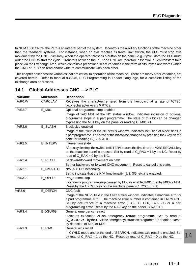
en-938979/0 14 - 3
PLC Diagnostics
14
In NUM 1060 CNCs, the PLC is an integral part of the system. It controls the auxiliary functions of the machine otherthan the feedback systems. For instance, when an axis reaches its travel limit switch, the PLC must stop axismovement by the CNC. Similarly, when the operator presses a button on the panel, e.g. Cycle Start, the PLC mustorder the CNC to start the cycle. Transfers between the PLC and CNC are therefore essential. Such transfers takeplace via the Exchange Area, which contains a predefined set of variables in the form of bits, bytes and words whichthe CNC or PLC can read and/or write to communicate with each other.
This chapter describes the variables that are critical to operation of the machine. There are many other variables, notcovered herein. Refer to manual 938846, PLC Programming in Ladder Language, for a complete listing of theexchange area addresses.
14.1 Global Addresses CNC —> PLCVariable Mnemonic Description%R0.W CARCLAV Receives the characters entered from the keyboard at a rate of %TS5,
i.e.onecharacter every 5 RTCs.%R2.7 E_M01 Optional programme stop enabled
Image of field M01 of the NC status window. Indicates inclusion of optionalprogramme stops in a part programme. The state of this bit can be changedbypressing the M01 key on the panel or reading C_M01 =1.
%R2.6 E_SLASH Block skip enabledImage of the / field of the NC status window. Indicates inclusion of block skips ina part programme. The state of the bit can be changed by pressing the / key on thepanel or reading C_SLASH =1.
%R2.5 E_INTERV Intervention stateAfter a cycle stop, the switch to INTERV occurs the first time the AXIS RECALL keyon the machine panel is pressed. Set by read of C_RAX = 1 by the NC. Reset byread of C_RAX = 0 by the NC.
%R2.4 S_RECUL Backward/forward movement on pathSet for backward or forward CNC movement. Reset to cancel this state.
%R2.1 E_NMAUTO N/M AUTO functionalitySet to indicate that the N/M functionality (2/3, 3/5, etc.) is enabled.
%R3.7 E_OPER Programme stopIndicates a programme stop caused by M00 or enabled M01. Set by M00 or M01.Reset by the CYCLE key on the machine panel (C_CYCLE = 1)
%R3.6 E_DEFCN CNC faultImage of the NC?? field in the CNC status window. Indicates a machine error ora part programme error. The machine error number is contained in ERRMACH.Set by occurrence of a machine error (E30-E33, E36, E40-E71) or a partprogramming error. Reset by the RAZ key on the panel, C RAZ = 1.
%R3.4 E DGURG General emergency retractIndicates execution of an emergency retract programme. Set by read ofC_DGURG = 1 by the NC if the emergency retraction programme is enabled. Resetby detection of M00 or M02.
%R3.3 E_RAX General axis recallIn CYHLD mode and at the end of SEARCH, indicates axis recall is enabled. Setby read of C_RAX = 1 by the NC. Reset by read of C_RAX = 0 by the NC.
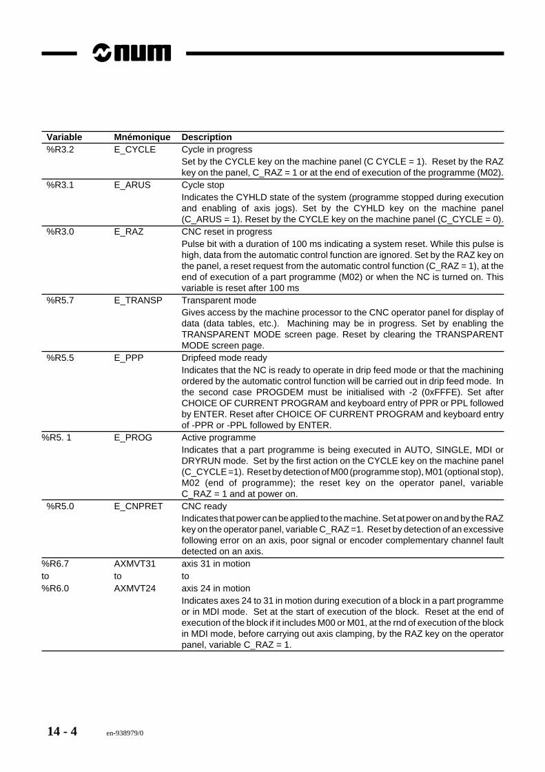
14 - 4 en-938979/0
Variable Mnémonique Description%R3.2 E_CYCLE Cycle in progress
Set by the CYCLE key on the machine panel (C CYCLE = 1). Reset by the RAZkey on the panel, C_RAZ = 1 or at the end of execution of the programme (M02).
%R3.1 E_ARUS Cycle stopIndicates the CYHLD state of the system (programme stopped during executionand enabling of axis jogs). Set by the CYHLD key on the machine panel(C_ARUS = 1). Reset by the CYCLE key on the machine panel (C_CYCLE = 0).
%R3.0 E_RAZ CNC reset in progressPulse bit with a duration of 100 ms indicating a system reset. While this pulse ishigh, data from the automatic control function are ignored. Set by the RAZ key onthe panel, a reset request from the automatic control function (C_RAZ = 1), at theend of execution of a part programme (M02) or when the NC is turned on. Thisvariable is reset after 100 ms
%R5.7 E_TRANSP Transparent modeGives access by the machine processor to the CNC operator panel for display ofdata (data tables, etc.). Machining may be in progress. Set by enabling theTRANSPARENT MODE screen page. Reset by clearing the TRANSPARENTMODE screen page.
%R5.5 E_PPP Dripfeed mode readyIndicates that the NC is ready to operate in drip feed mode or that the machiningordered by the automatic control function will be carried out in drip feed mode. Inthe second case PROGDEM must be initialised with -2 (0xFFFE). Set afterCHOICE OF CURRENT PROGRAM and keyboard entry of PPR or PPL followedby ENTER. Reset after CHOICE OF CURRENT PROGRAM and keyboard entryof -PPR or -PPL followed by ENTER.
%R5. 1 E_PROG Active programmeIndicates that a part programme is being executed in AUTO, SINGLE, MDI orDRYRUN mode. Set by the first action on the CYCLE key on the machine panel(C_CYCLE =1). Reset by detection of M00 (programme stop), M01 (optional stop),M02 (end of programme); the reset key on the operator panel, variableC_RAZ = 1 and at power on.
%R5.0 E_CNPRET CNC readyIndicates that power can be applied to the machine. Set at power on and by the RAZkey on the operator panel, variable C_RAZ =1. Reset by detection of an excessivefollowing error on an axis, poor signal or encoder complementary channel faultdetected on an axis.
%R6.7 AXMVT31 axis 31 in motionto to to%R6.0 AXMVT24 axis 24 in motion
Indicates axes 24 to 31 in motion during execution of a block in a part programmeor in MDI mode. Set at the start of execution of the block. Reset at the end ofexecution of the block if it includes M00 or M01, at the rnd of execution of the blockin MDI mode, before carrying out axis clamping, by the RAZ key on the operatorpanel, variable C_RAZ = 1.
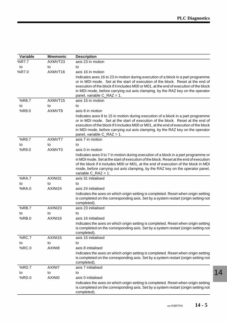
en-938979/0 14 - 5
PLC Diagnostics
14
Variable Mnemonic Description%R7.7 AXMVT23 axis 23 in motionto to to
%R7.0 AXMVT16 axis 16 in motionIndicates axes 16 to 23 in motion during execution of a block in a part programmeor in MDI mode. Set at the start of execution of the block. Reset at the end ofexecution of the block if it includes M00 or M01, at the end of execution of the blockin MDI mode, before carrying out axis clamping. by the RAZ key on the operatorpanel, variable C_RAZ = 1.
%R8.7 AXMVT15 axis 15 in motionto to to%R8.0 AXMVT8 axis 8 in motion
Indicates axes 8 to 15 in motion during execution of a block in a part programmeor in MDI mode. Set at the start of execution of the block. Reset at the end ofexecution of the block if it includes M00 or M01, at the end of execution of the blockin MDI mode, before carrying out axis clamping. by the RAZ key on the operatorpanel, variable C_RAZ = 1.
%R9.7 AXMVT7 axis 7 in motionto to to%R9.0 AXMVT0 axis 0 in motion
Indicates axes 0 to 7 in motion during execution of a block in a part programme orin MDI mode. Set at the start of execution of the block. Reset at the end of executionof the block if it includes M00 or M01, at the end of execution of the block in MDImode, before carrying out axis clamping, by the RAZ key on the operator panel,variable C_RAZ = 1.
%RA.7 AXINI31 axis 31 initialisedto to to%RA.0 AXINI24 axis 24 initialised
Indicates the axes on which origin setting is completed. Reset when origin settingis completed on the corresponding axis. Set by a system restart (origin setting notcompleted).
%RB.7 AXINI23 axis 23 initialisedto to to%RB.0 AXINI16 axis 16 initialised
Indicates the axes on which origin setting is completed. Reset when origin settingis completed on the corresponding axis. Set by a system restart (origin setting notcompleted).
%RC.7 AXINI15 axis 15 initialisedto to to%RC.0 AXINI8 axis 8 initialised
Indicates the axes on which origin setting is completed. Reset when origin settingis completed on the corresponding axis. Set by a system restart (origin setting notcompleted).
%RD.7 AXINI7 axis 7 initialisedto to to%RD.0 AXINI0 axis 0 initialised
Indicates the axes on which origin setting is completed. Reset when origin settingis completed on the corresponding axis. Set by a system restart (origin setting notcompleted).
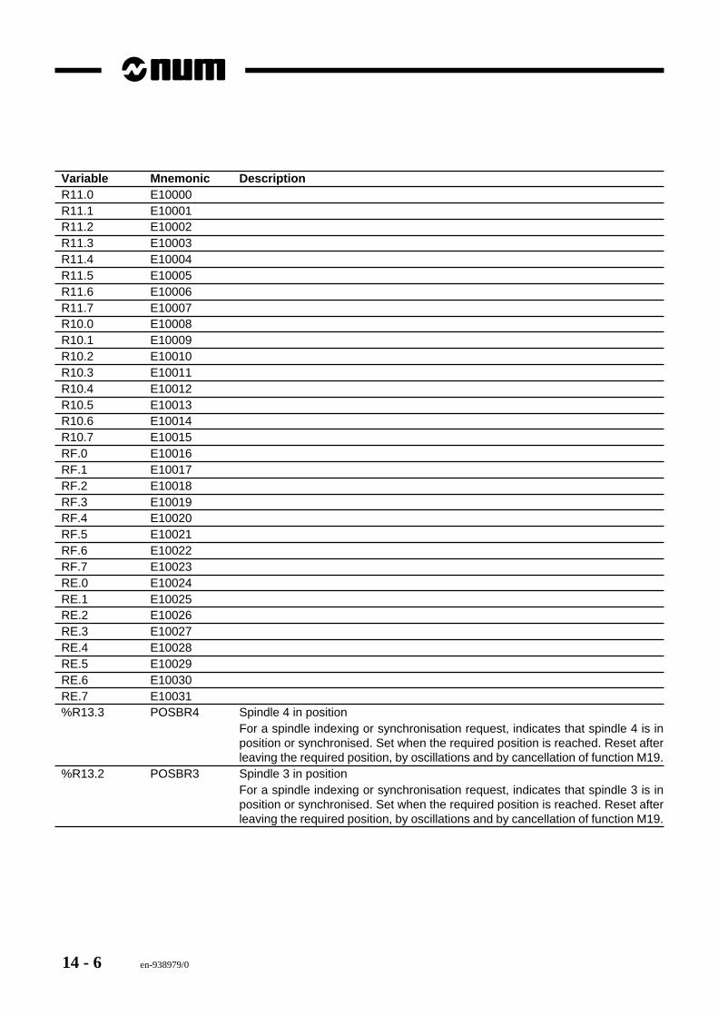
14 - 6 en-938979/0
Variable Mnemonic DescriptionR11.0 E10000R11.1 E10001R11.2 E10002R11.3 E10003R11.4 E10004R11.5 E10005R11.6 E10006R11.7 E10007R10.0 E10008R10.1 E10009R10.2 E10010R10.3 E10011R10.4 E10012R10.5 E10013R10.6 E10014R10.7 E10015RF.0 E10016RF.1 E10017RF.2 E10018RF.3 E10019RF.4 E10020RF.5 E10021RF.6 E10022RF.7 E10023RE.0 E10024RE.1 E10025RE.2 E10026RE.3 E10027RE.4 E10028RE.5 E10029RE.6 E10030RE.7 E10031%R13.3 POSBR4 Spindle 4 in position
For a spindle indexing or synchronisation request, indicates that spindle 4 is inposition or synchronised. Set when the required position is reached. Reset afterleaving the required position, by oscillations and by cancellation of function M19.
%R13.2 POSBR3 Spindle 3 in positionFor a spindle indexing or synchronisation request, indicates that spindle 3 is inposition or synchronised. Set when the required position is reached. Reset afterleaving the required position, by oscillations and by cancellation of function M19.
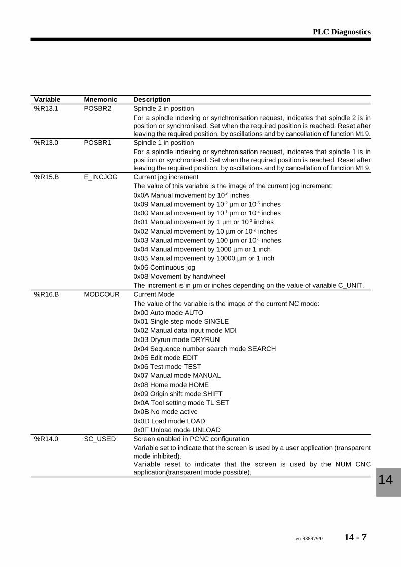
en-938979/0 14 - 7
PLC Diagnostics
14
Variable Mnemonic Description%R13.1 POSBR2 Spindle 2 in position
For a spindle indexing or synchronisation request, indicates that spindle 2 is inposition or synchronised. Set when the required position is reached. Reset afterleaving the required position, by oscillations and by cancellation of function M19.
%R13.0 POSBR1 Spindle 1 in positionFor a spindle indexing or synchronisation request, indicates that spindle 1 is inposition or synchronised. Set when the required position is reached. Reset afterleaving the required position, by oscillations and by cancellation of function M19.
%R15.B E_INCJOG Current jog incrementThe value of this variable is the image of the current jog increment:0x0A Manual movement by 10-6 inches0x09 Manual movement by 10-2 µm or 10-5 inches0x00 Manual movement by 10-1 µm or 10-4 inches0x01 Manual movement by 1 µm or 10-3 inches0x02 Manual movement by 10 µm or 10-2 inches0x03 Manual movement by 100 µm or 10-1 inches0x04 Manual movement by 1000 µm or 1 inch0x05 Manual movement by 10000 µm or 1 inch0x06 Continuous jog0x08 Movement by handwheelThe increment is in µm or inches depending on the value of variable C_UNIT.
%R16.B MODCOUR Current ModeThe value of the variable is the image of the current NC mode:0x00 Auto mode AUTO0x01 Single step mode SINGLE0x02 Manual data input mode MDI0x03 Dryrun mode DRYRUN0x04 Sequence number search mode SEARCH0x05 Edit mode EDIT0x06 Test mode TEST0x07 Manual mode MANUAL0x08 Home mode HOME0x09 Origin shift mode SHIFT0x0A Tool setting mode TL SET0x0B No mode active0x0D Load mode LOAD0x0F Unload mode UNLOAD
%R14.0 SC_USED Screen enabled in PCNC configurationVariable set to indicate that the screen is used by a user application (transparentmode inhibited).Variable reset to indicate that the screen is used by the NUM CNCapplication(transparent mode possible).
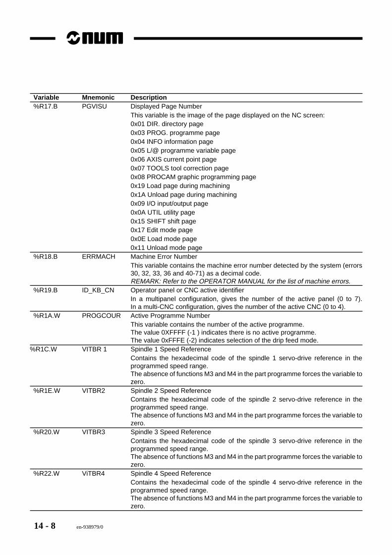
14 - 8 en-938979/0
Variable Mnemonic Description%R17.B PGVISU Displayed Page Number
This variable is the image of the page displayed on the NC screen:0x01 DIR. directory page0x03 PROG. programme page0x04 INFO information page0x05 L/@ programme variable page0x06 AXIS current point page0x07 TOOLS tool correction page0x08 PROCAM graphic programming page0x19 Load page during machining0x1A Unload page during machining0x09 I/O input/output page0x0A UTIL utility page0x15 SHIFT shift page0x17 Edit mode page0x0E Load mode page0x11 Unload mode page
%R18.B ERRMACH Machine Error NumberThis variable contains the machine error number detected by the system (errors30, 32, 33, 36 and 40-71) as a decimal code.REMARK: Refer to the OPERATOR MANUAL for the list of machine errors.
%R19.B ID_KB_CN Operator panel or CNC active identifierIn a multipanel configuration, gives the number of the active panel (0 to 7).In a multi-CNC configuration, gives the number of the active CNC (0 to 4).
%R1A.W PROGCOUR Active Programme NumberThis variable contains the number of the active programme.The value 0XFFFF (-1 ) indicates there is no active programme.The value 0xFFFE (-2) indicates selection of the drip feed mode.
%R1C.W VITBR 1 Spindle 1 Speed ReferenceContains the hexadecimal code of the spindle 1 servo-drive reference in theprogrammed speed range.The absence of functions M3 and M4 in the part programme forces the variable tozero.
%R1E.W VITBR2 Spindle 2 Speed ReferenceContains the hexadecimal code of the spindle 2 servo-drive reference in theprogrammed speed range.The absence of functions M3 and M4 in the part programme forces the variable tozero.
%R20.W VITBR3 Spindle 3 Speed ReferenceContains the hexadecimal code of the spindle 3 servo-drive reference in theprogrammed speed range.The absence of functions M3 and M4 in the part programme forces the variable tozero.
%R22.W ViTBR4 Spindle 4 Speed ReferenceContains the hexadecimal code of the spindle 4 servo-drive reference in theprogrammed speed range.The absence of functions M3 and M4 in the part programme forces the variable tozero.
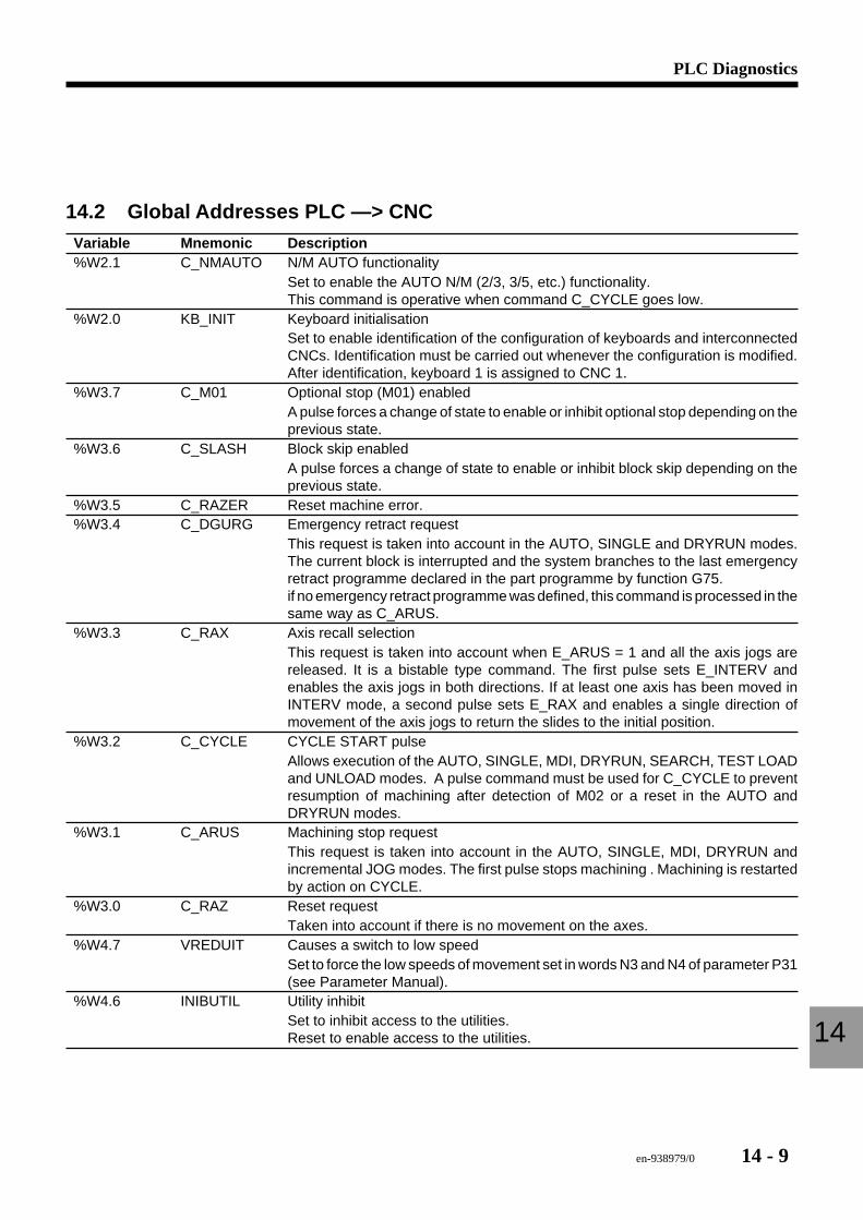
en-938979/0 14 - 9
PLC Diagnostics
14
14.2 Global Addresses PLC —> CNCVariable Mnemonic Description%W2.1 C_NMAUTO N/M AUTO functionality
Set to enable the AUTO N/M (2/3, 3/5, etc.) functionality.This command is operative when command C_CYCLE goes low.
%W2.0 KB_INIT Keyboard initialisationSet to enable identification of the configuration of keyboards and interconnectedCNCs. Identification must be carried out whenever the configuration is modified.After identification, keyboard 1 is assigned to CNC 1.
%W3.7 C_M01 Optional stop (M01) enabledA pulse forces a change of state to enable or inhibit optional stop depending on theprevious state.
%W3.6 C_SLASH Block skip enabledA pulse forces a change of state to enable or inhibit block skip depending on theprevious state.
%W3.5 C_RAZER Reset machine error.%W3.4 C_DGURG Emergency retract request
This request is taken into account in the AUTO, SINGLE and DRYRUN modes.The current block is interrupted and the system branches to the last emergencyretract programme declared in the part programme by function G75.if no emergency retract programme was defined, this command is processed in thesame way as C_ARUS.
%W3.3 C_RAX Axis recall selectionThis request is taken into account when E_ARUS = 1 and all the axis jogs arereleased. It is a bistable type command. The first pulse sets E_INTERV andenables the axis jogs in both directions. If at least one axis has been moved inINTERV mode, a second pulse sets E_RAX and enables a single direction ofmovement of the axis jogs to return the slides to the initial position.
%W3.2 C_CYCLE CYCLE START pulseAllows execution of the AUTO, SINGLE, MDI, DRYRUN, SEARCH, TEST LOADand UNLOAD modes. A pulse command must be used for C_CYCLE to preventresumption of machining after detection of M02 or a reset in the AUTO andDRYRUN modes.
%W3.1 C_ARUS Machining stop requestThis request is taken into account in the AUTO, SINGLE, MDI, DRYRUN andincremental JOG modes. The first pulse stops machining . Machining is restartedby action on CYCLE.
%W3.0 C_RAZ Reset requestTaken into account if there is no movement on the axes.
%W4.7 VREDUIT Causes a switch to low speedSet to force the low speeds of movement set in words N3 and N4 of parameter P31(see Parameter Manual).
%W4.6 INIBUTIL Utility inhibitSet to inhibit access to the utilities.Reset to enable access to the utilities.
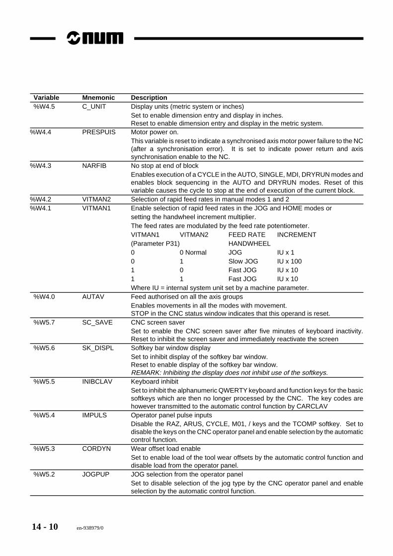
14 - 10 en-938979/0
Variable Mnemonic Description%W4.5 C_UNIT Display units (metric system or inches)
Set to enable dimension entry and display in inches.Reset to enable dimension entry and display in the metric system.
%W4.4 PRESPUIS Motor power on.This variable is reset to indicate a synchronised axis motor power failure to the NC(after a synchronisation error). It is set to indicate power return and axissynchronisation enable to the NC.
%W4.3 NARFIB No stop at end of blockEnables execution of a CYCLE in the AUTO, SINGLE, MDI, DRYRUN modes andenables block sequencing in the AUTO and DRYRUN modes. Reset of thisvariable causes the cycle to stop at the end of execution of the current block.
%W4.2 VITMAN2 Selection of rapid feed rates in manual modes 1 and 2%W4.1 VITMAN1 Enable selection of rapid feed rates in the JOG and HOME modes or
setting the handwheel increment multiplier.The feed rates are modulated by the feed rate potentiometer.VITMAN1 VITMAN2 FEED RATE INCREMENT(Parameter P31) HANDWHEEL0 0 Normal JOG IU x 10 1 Slow JOG IU x 1001 0 Fast JOG IU x 101 1 Fast JOG IU x 10Where IU = internal system unit set by a machine parameter.
%W4.0 AUTAV Feed authorised on all the axis groupsEnables movements in all the modes with movement.STOP in the CNC status window indicates that this operand is reset.
%W5.7 SC_SAVE CNC screen saverSet to enable the CNC screen saver after five minutes of keyboard inactivity.Reset to inhibit the screen saver and immediately reactivate the screen
%W5.6 SK_DISPL Softkey bar window displaySet to inhibit display of the softkey bar window.Reset to enable display of the softkey bar window.REMARK: Inhibiting the display does not inhibit use of the softkeys.
%W5.5 INIBCLAV Keyboard inhibitSet to inhibit the alphanumeric QWERTY keyboard and function keys for the basicsoftkeys which are then no longer processed by the CNC. The key codes arehowever transmitted to the automatic control function by CARCLAV
%W5.4 IMPULS Operator panel pulse inputsDisable the RAZ, ARUS, CYCLE, M01, / keys and the TCOMP softkey. Set todisable the keys on the CNC operator panel and enable selection by the automaticcontrol function.
%W5.3 CORDYN Wear offset load enableSet to enable load of the tool wear offsets by the automatic control function anddisable load from the operator panel.
%W5.2 JOGPUP JOG selection from the operator panelSet to disable selection of the jog type by the CNC operator panel and enableselection by the automatic control function.
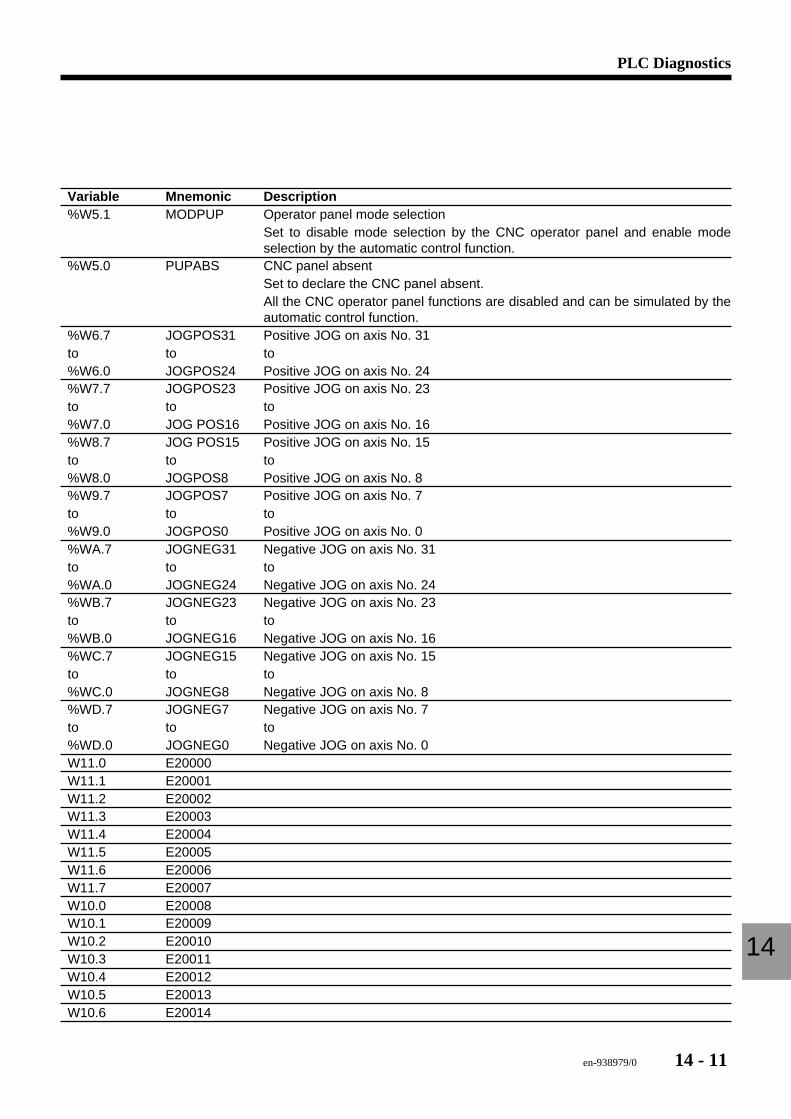
en-938979/0 14 - 11
PLC Diagnostics
14
Variable Mnemonic Description%W5.1 MODPUP Operator panel mode selection
Set to disable mode selection by the CNC operator panel and enable modeselection by the automatic control function.
%W5.0 PUPABS CNC panel absentSet to declare the CNC panel absent.All the CNC operator panel functions are disabled and can be simulated by theautomatic control function.
%W6.7 JOGPOS31 Positive JOG on axis No. 31to to to%W6.0 JOGPOS24 Positive JOG on axis No. 24%W7.7 JOGPOS23 Positive JOG on axis No. 23to to to%W7.0 JOG POS16 Positive JOG on axis No. 16%W8.7 JOG POS15 Positive JOG on axis No. 15to to to%W8.0 JOGPOS8 Positive JOG on axis No. 8%W9.7 JOGPOS7 Positive JOG on axis No. 7to to to%W9.0 JOGPOS0 Positive JOG on axis No. 0%WA.7 JOGNEG31 Negative JOG on axis No. 31to to to%WA.0 JOGNEG24 Negative JOG on axis No. 24%WB.7 JOGNEG23 Negative JOG on axis No. 23to to to%WB.0 JOGNEG16 Negative JOG on axis No. 16%WC.7 JOGNEG15 Negative JOG on axis No. 15to to to%WC.0 JOGNEG8 Negative JOG on axis No. 8%WD.7 JOGNEG7 Negative JOG on axis No. 7to to to%WD.0 JOGNEG0 Negative JOG on axis No. 0W11.0 E20000W11.1 E20001W11.2 E20002W11.3 E20003W11.4 E20004W11.5 E20005W11.6 E20006W11.7 E20007W10.0 E20008W10.1 E20009W10.2 E20010W10.3 E20011W10.4 E20012W10.5 E20013W10.6 E20014
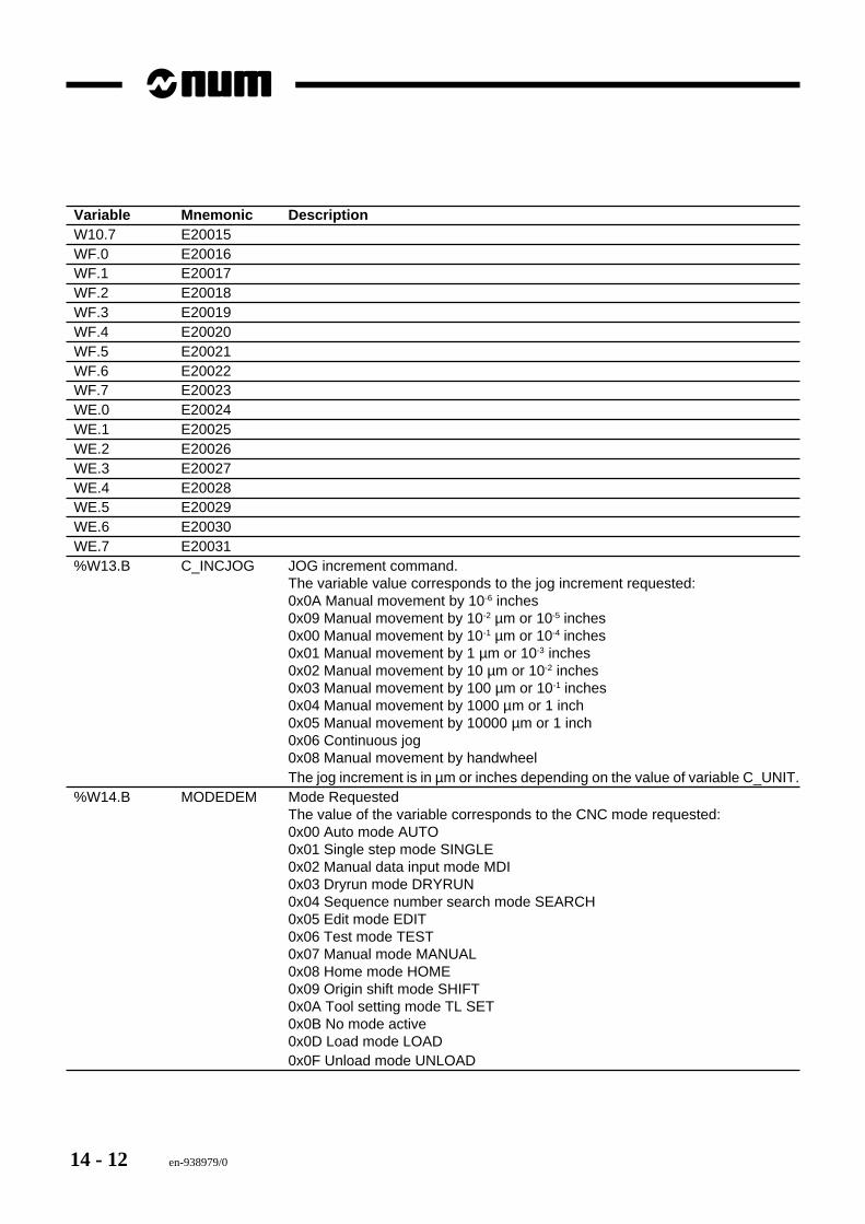
14 - 12 en-938979/0
Variable Mnemonic DescriptionW10.7 E20015WF.0 E20016WF.1 E20017WF.2 E20018WF.3 E20019WF.4 E20020WF.5 E20021WF.6 E20022WF.7 E20023WE.0 E20024WE.1 E20025WE.2 E20026WE.3 E20027WE.4 E20028WE.5 E20029WE.6 E20030WE.7 E20031%W13.B C_INCJOG JOG increment command.
The variable value corresponds to the jog increment requested:0x0A Manual movement by 10-6 inches0x09 Manual movement by 10-2 µm or 10-5 inches0x00 Manual movement by 10-1 µm or 10-4 inches0x01 Manual movement by 1 µm or 10-3 inches0x02 Manual movement by 10 µm or 10-2 inches0x03 Manual movement by 100 µm or 10-1 inches0x04 Manual movement by 1000 µm or 1 inch0x05 Manual movement by 10000 µm or 1 inch0x06 Continuous jog0x08 Manual movement by handwheelThe jog increment is in µm or inches depending on the value of variable C_UNIT.
%W14.B MODEDEM Mode RequestedThe value of the variable corresponds to the CNC mode requested:0x00 Auto mode AUTO0x01 Single step mode SINGLE0x02 Manual data input mode MDI0x03 Dryrun mode DRYRUN0x04 Sequence number search mode SEARCH0x05 Edit mode EDIT0x06 Test mode TEST0x07 Manual mode MANUAL0x08 Home mode HOME0x09 Origin shift mode SHIFT0x0A Tool setting mode TL SET0x0B No mode active0x0D Load mode LOAD0x0F Unload mode UNLOAD
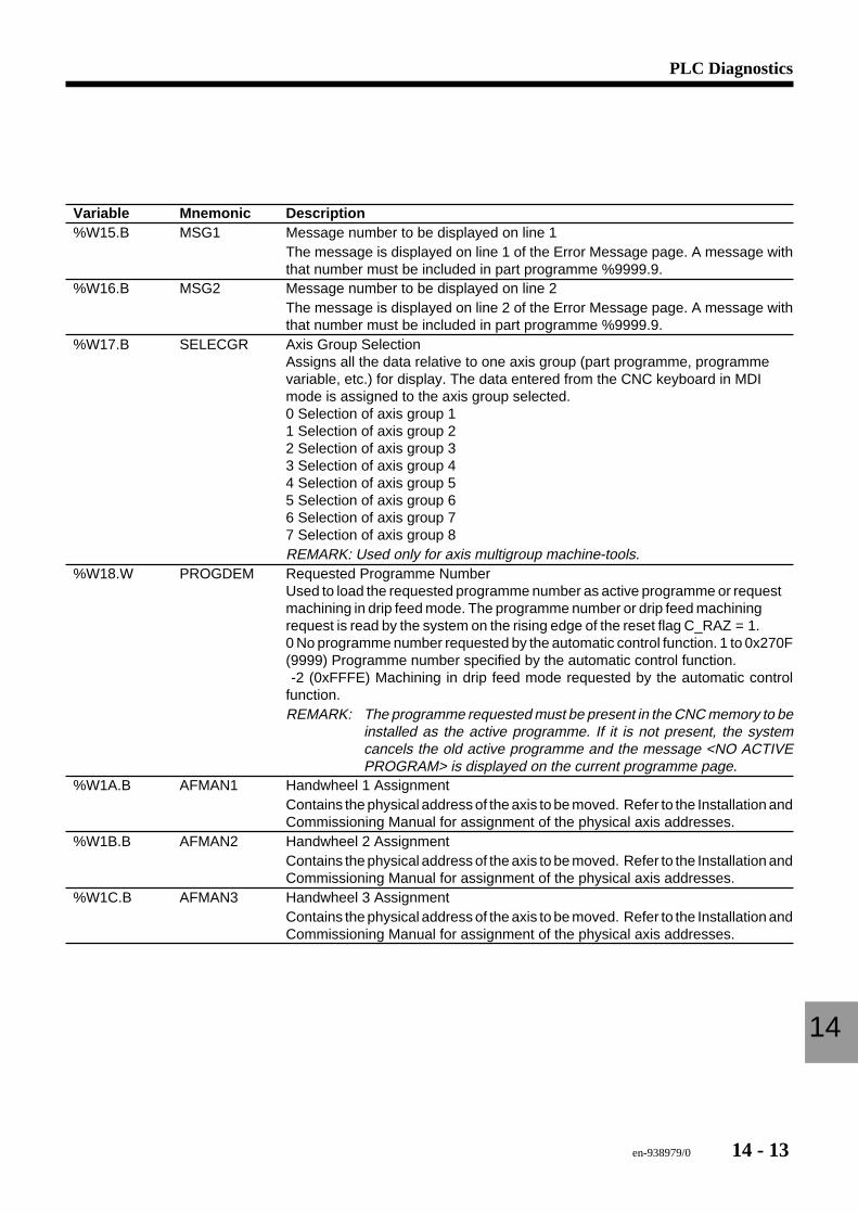
en-938979/0 14 - 13
PLC Diagnostics
14
Variable Mnemonic Description%W15.B MSG1 Message number to be displayed on line 1
The message is displayed on line 1 of the Error Message page. A message withthat number must be included in part programme %9999.9.
%W16.B MSG2 Message number to be displayed on line 2The message is displayed on line 2 of the Error Message page. A message withthat number must be included in part programme %9999.9.
%W17.B SELECGR Axis Group SelectionAssigns all the data relative to one axis group (part programme, programmevariable, etc.) for display. The data entered from the CNC keyboard in MDImode is assigned to the axis group selected.0 Selection of axis group 11 Selection of axis group 22 Selection of axis group 33 Selection of axis group 44 Selection of axis group 55 Selection of axis group 66 Selection of axis group 77 Selection of axis group 8REMARK: Used only for axis multigroup machine-tools.
%W18.W PROGDEM Requested Programme NumberUsed to load the requested programme number as active programme or requestmachining in drip feed mode. The programme number or drip feed machiningrequest is read by the system on the rising edge of the reset flag C_RAZ = 1.0 No programme number requested by the automatic control function. 1 to 0x270F(9999) Programme number specified by the automatic control function. -2 (0xFFFE) Machining in drip feed mode requested by the automatic controlfunction.REMARK: The programme requested must be present in the CNC memory to be
installed as the active programme. If it is not present, the systemcancels the old active programme and the message <NO ACTIVEPROGRAM> is displayed on the current programme page.
%W1A.B AFMAN1 Handwheel 1 AssignmentContains the physical address of the axis to be moved. Refer to the Installation andCommissioning Manual for assignment of the physical axis addresses.
%W1B.B AFMAN2 Handwheel 2 AssignmentContains the physical address of the axis to be moved. Refer to the Installation andCommissioning Manual for assignment of the physical axis addresses.
%W1C.B AFMAN3 Handwheel 3 AssignmentContains the physical address of the axis to be moved. Refer to the Installation andCommissioning Manual for assignment of the physical axis addresses.
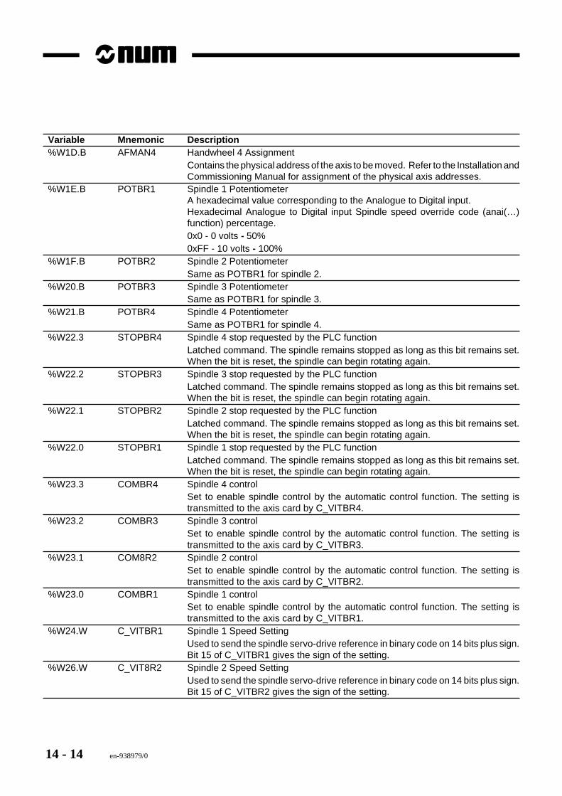
14 - 14 en-938979/0
Variable Mnemonic Description%W1D.B AFMAN4 Handwheel 4 Assignment
Contains the physical address of the axis to be moved. Refer to the Installation andCommissioning Manual for assignment of the physical axis addresses.
%W1E.B POTBR1 Spindle 1 PotentiometerA hexadecimal value corresponding to the Analogue to Digital input.Hexadecimal Analogue to Digital input Spindle speed override code (anai(…)function) percentage.0x0 - 0 volts - 50%0xFF - 10 volts - 100%
%W1F.B POTBR2 Spindle 2 PotentiometerSame as POTBR1 for spindle 2.
%W20.B POTBR3 Spindle 3 PotentiometerSame as POTBR1 for spindle 3.
%W21.B POTBR4 Spindle 4 PotentiometerSame as POTBR1 for spindle 4.
%W22.3 STOPBR4 Spindle 4 stop requested by the PLC functionLatched command. The spindle remains stopped as long as this bit remains set.When the bit is reset, the spindle can begin rotating again.
%W22.2 STOPBR3 Spindle 3 stop requested by the PLC functionLatched command. The spindle remains stopped as long as this bit remains set.When the bit is reset, the spindle can begin rotating again.
%W22.1 STOPBR2 Spindle 2 stop requested by the PLC functionLatched command. The spindle remains stopped as long as this bit remains set.When the bit is reset, the spindle can begin rotating again.
%W22.0 STOPBR1 Spindle 1 stop requested by the PLC functionLatched command. The spindle remains stopped as long as this bit remains set.When the bit is reset, the spindle can begin rotating again.
%W23.3 COMBR4 Spindle 4 controlSet to enable spindle control by the automatic control function. The setting istransmitted to the axis card by C_VITBR4.
%W23.2 COMBR3 Spindle 3 controlSet to enable spindle control by the automatic control function. The setting istransmitted to the axis card by C_VITBR3.
%W23.1 COM8R2 Spindle 2 controlSet to enable spindle control by the automatic control function. The setting istransmitted to the axis card by C_VITBR2.
%W23.0 COMBR1 Spindle 1 controlSet to enable spindle control by the automatic control function. The setting istransmitted to the axis card by C_VITBR1.
%W24.W C_VITBR1 Spindle 1 Speed SettingUsed to send the spindle servo-drive reference in binary code on 14 bits plus sign.Bit 15 of C_VITBR1 gives the sign of the setting.
%W26.W C_VIT8R2 Spindle 2 Speed SettingUsed to send the spindle servo-drive reference in binary code on 14 bits plus sign.Bit 15 of C_VITBR2 gives the sign of the setting.
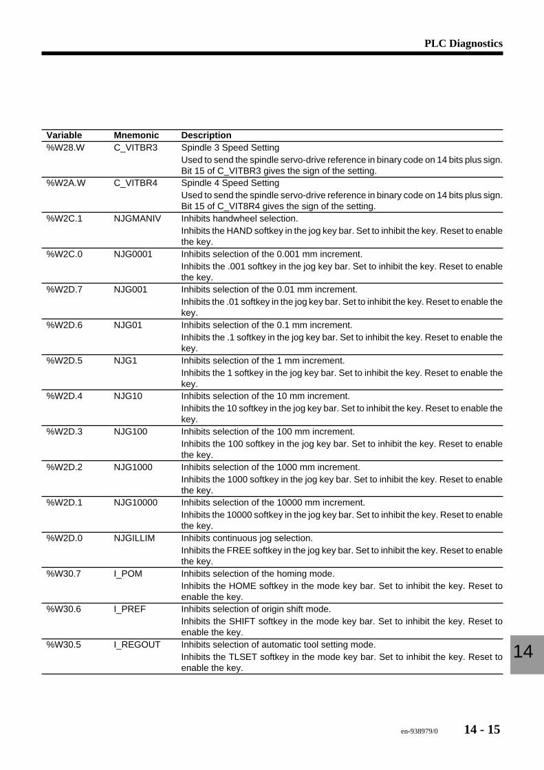
en-938979/0 14 - 15
PLC Diagnostics
14
Variable Mnemonic Description%W28.W C_VITBR3 Spindle 3 Speed Setting
Used to send the spindle servo-drive reference in binary code on 14 bits plus sign.Bit 15 of C_VITBR3 gives the sign of the setting.
%W2A.W C_VITBR4 Spindle 4 Speed SettingUsed to send the spindle servo-drive reference in binary code on 14 bits plus sign.Bit 15 of C_VIT8R4 gives the sign of the setting.
%W2C.1 NJGMANIV Inhibits handwheel selection.Inhibits the HAND softkey in the jog key bar. Set to inhibit the key. Reset to enablethe key.
%W2C.0 NJG0001 Inhibits selection of the 0.001 mm increment.Inhibits the .001 softkey in the jog key bar. Set to inhibit the key. Reset to enablethe key.
%W2D.7 NJG001 Inhibits selection of the 0.01 mm increment.Inhibits the .01 softkey in the jog key bar. Set to inhibit the key. Reset to enable thekey.
%W2D.6 NJG01 Inhibits selection of the 0.1 mm increment.Inhibits the .1 softkey in the jog key bar. Set to inhibit the key. Reset to enable thekey.
%W2D.5 NJG1 Inhibits selection of the 1 mm increment.Inhibits the 1 softkey in the jog key bar. Set to inhibit the key. Reset to enable thekey.
%W2D.4 NJG10 Inhibits selection of the 10 mm increment.Inhibits the 10 softkey in the jog key bar. Set to inhibit the key. Reset to enable thekey.
%W2D.3 NJG100 Inhibits selection of the 100 mm increment.Inhibits the 100 softkey in the jog key bar. Set to inhibit the key. Reset to enablethe key.
%W2D.2 NJG1000 Inhibits selection of the 1000 mm increment.Inhibits the 1000 softkey in the jog key bar. Set to inhibit the key. Reset to enablethe key.
%W2D.1 NJG10000 Inhibits selection of the 10000 mm increment.Inhibits the 10000 softkey in the jog key bar. Set to inhibit the key. Reset to enablethe key.
%W2D.0 NJGILLIM Inhibits continuous jog selection.Inhibits the FREE softkey in the jog key bar. Set to inhibit the key. Reset to enablethe key.
%W30.7 I_POM Inhibits selection of the homing mode.Inhibits the HOME softkey in the mode key bar. Set to inhibit the key. Reset toenable the key.
%W30.6 I_PREF Inhibits selection of origin shift mode.Inhibits the SHIFT softkey in the mode key bar. Set to inhibit the key. Reset toenable the key.
%W30.5 I_REGOUT Inhibits selection of automatic tool setting mode.Inhibits the TLSET softkey in the mode key bar. Set to inhibit the key. Reset toenable the key.
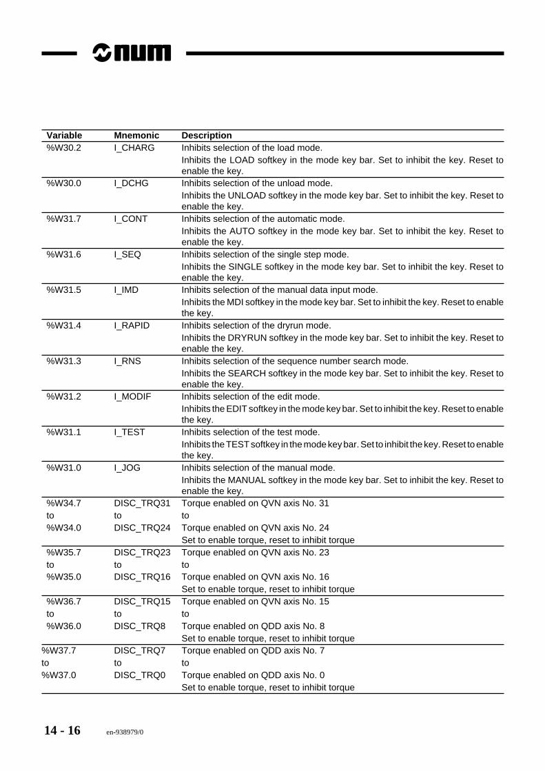
14 - 16 en-938979/0
Variable Mnemonic Description%W30.2 I_CHARG Inhibits selection of the load mode.
Inhibits the LOAD softkey in the mode key bar. Set to inhibit the key. Reset toenable the key.
%W30.0 I_DCHG Inhibits selection of the unload mode.Inhibits the UNLOAD softkey in the mode key bar. Set to inhibit the key. Reset toenable the key.
%W31.7 I_CONT Inhibits selection of the automatic mode.Inhibits the AUTO softkey in the mode key bar. Set to inhibit the key. Reset toenable the key.
%W31.6 I_SEQ Inhibits selection of the single step mode.Inhibits the SINGLE softkey in the mode key bar. Set to inhibit the key. Reset toenable the key.
%W31.5 I_IMD Inhibits selection of the manual data input mode.Inhibits the MDI softkey in the mode key bar. Set to inhibit the key. Reset to enablethe key.
%W31.4 I_RAPID Inhibits selection of the dryrun mode.Inhibits the DRYRUN softkey in the mode key bar. Set to inhibit the key. Reset toenable the key.
%W31.3 I_RNS Inhibits selection of the sequence number search mode.Inhibits the SEARCH softkey in the mode key bar. Set to inhibit the key. Reset toenable the key.
%W31.2 I_MODIF Inhibits selection of the edit mode.Inhibits the EDIT softkey in the mode key bar. Set to inhibit the key. Reset to enablethe key.
%W31.1 I_TEST Inhibits selection of the test mode.Inhibits the TEST softkey in the mode key bar. Set to inhibit the key. Reset to enablethe key.
%W31.0 I_JOG Inhibits selection of the manual mode.Inhibits the MANUAL softkey in the mode key bar. Set to inhibit the key. Reset toenable the key.
%W34.7 DISC_TRQ31 Torque enabled on QVN axis No. 31to to to%W34.0 DISC_TRQ24 Torque enabled on QVN axis No. 24
Set to enable torque, reset to inhibit torque%W35.7 DISC_TRQ23 Torque enabled on QVN axis No. 23to to to%W35.0 DISC_TRQ16 Torque enabled on QVN axis No. 16
Set to enable torque, reset to inhibit torque%W36.7 DISC_TRQ15 Torque enabled on QVN axis No. 15to to to%W36.0 DISC_TRQ8 Torque enabled on QDD axis No. 8
Set to enable torque, reset to inhibit torque%W37.7 DISC_TRQ7 Torque enabled on QDD axis No. 7to to to%W37.0 DISC_TRQ0 Torque enabled on QDD axis No. 0
Set to enable torque, reset to inhibit torque
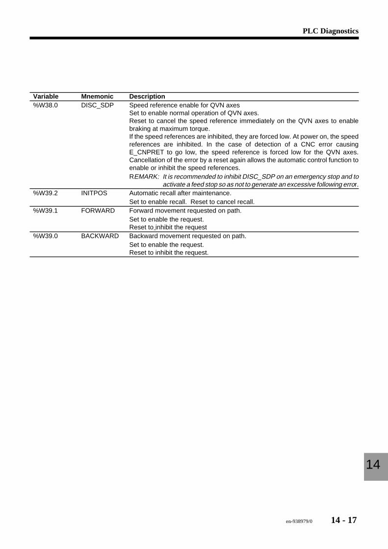
en-938979/0 14 - 17
PLC Diagnostics
14
Variable Mnemonic Description%W38.0 DISC_SDP Speed reference enable for QVN axes
Set to enable normal operation of QVN axes.Reset to cancel the speed reference immediately on the QVN axes to enablebraking at maximum torque.If the speed references are inhibited, they are forced low. At power on, the speedreferences are inhibited. In the case of detection of a CNC error causingE_CNPRET to go low, the speed reference is forced low for the QVN axes.Cancellation of the error by a reset again allows the automatic control function toenable or inhibit the speed references.REMARK: It is recommended to inhibit DISC_SDP on an emergency stop and to
activate a feed stop so as not to generate an excessive following error.%W39.2 INITPOS Automatic recall after maintenance.
Set to enable recall. Reset to cancel recall.%W39.1 FORWARD Forward movement requested on path.
Set to enable the request.Reset to inhibit the request
%W39.0 BACKWARD Backward movement requested on path.Set to enable the request.Reset to inhibit the request.
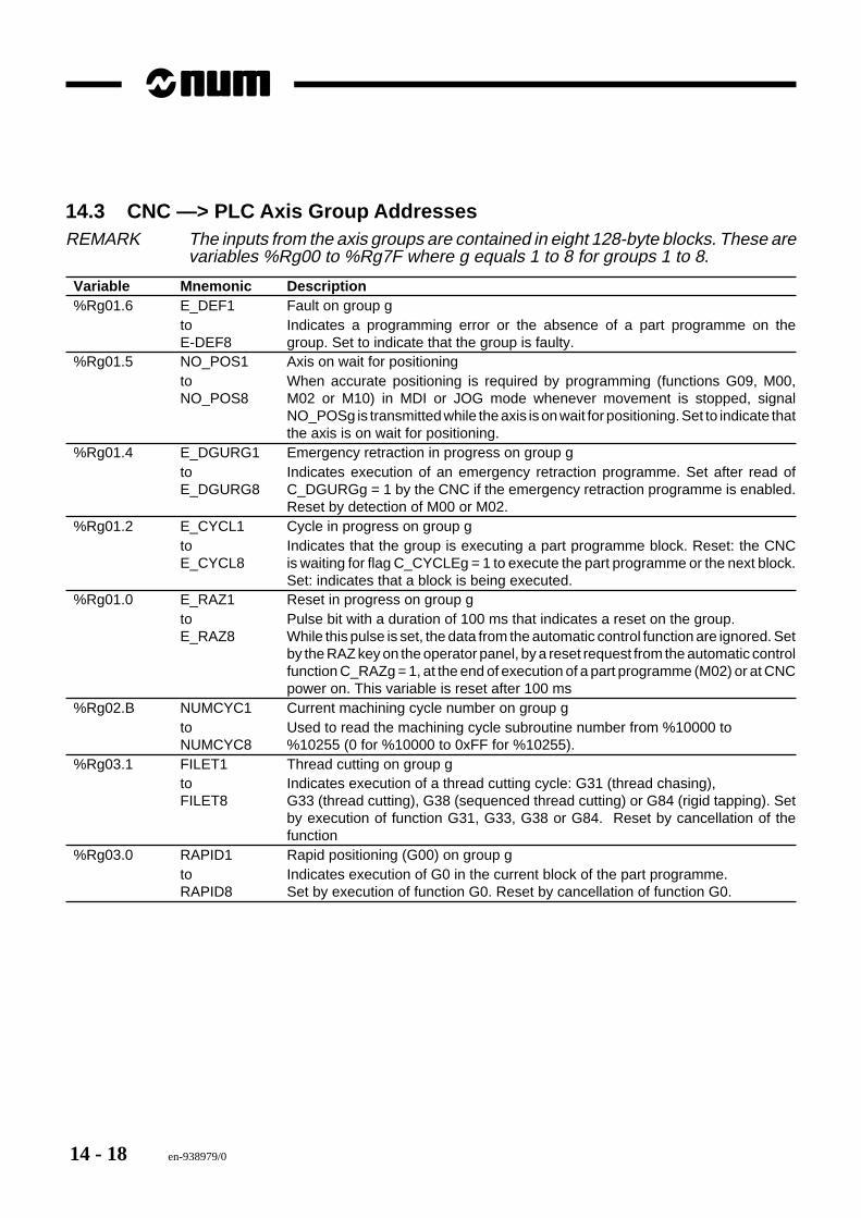
14 - 18 en-938979/0
14.3 CNC —> PLC Axis Group AddressesREMARK The inputs from the axis groups are contained in eight 128-byte blocks. These are
variables %Rg00 to %Rg7F where g equals 1 to 8 for groups 1 to 8.
Variable Mnemonic Description%Rg01.6 E_DEF1 Fault on group g
to Indicates a programming error or the absence of a part programme on theE-DEF8 group. Set to indicate that the group is faulty.
%Rg01.5 NO_POS1 Axis on wait for positioningto When accurate positioning is required by programming (functions G09, M00,NO_POS8 M02 or M10) in MDI or JOG mode whenever movement is stopped, signal
NO_POSg is transmitted while the axis is on wait for positioning. Set to indicate thatthe axis is on wait for positioning.
%Rg01.4 E_DGURG1 Emergency retraction in progress on group gto Indicates execution of an emergency retraction programme. Set after read ofE_DGURG8 C_DGURGg = 1 by the CNC if the emergency retraction programme is enabled.
Reset by detection of M00 or M02.%Rg01.2 E_CYCL1 Cycle in progress on group g
to Indicates that the group is executing a part programme block. Reset: the CNCE_CYCL8 is waiting for flag C_CYCLEg = 1 to execute the part programme or the next block.
Set: indicates that a block is being executed.%Rg01.0 E_RAZ1 Reset in progress on group g
to Pulse bit with a duration of 100 ms that indicates a reset on the group.E_RAZ8 While this pulse is set, the data from the automatic control function are ignored. Set
by the RAZ key on the operator panel, by a reset request from the automatic controlfunction C_RAZg = 1, at the end of execution of a part programme (M02) or at CNCpower on. This variable is reset after 100 ms
%Rg02.B NUMCYC1 Current machining cycle number on group gto Used to read the machining cycle subroutine number from %10000 toNUMCYC8 %10255 (0 for %10000 to 0xFF for %10255).
%Rg03.1 FILET1 Thread cutting on group gto Indicates execution of a thread cutting cycle: G31 (thread chasing),FILET8 G33 (thread cutting), G38 (sequenced thread cutting) or G84 (rigid tapping). Set
by execution of function G31, G33, G38 or G84. Reset by cancellation of thefunction
%Rg03.0 RAPID1 Rapid positioning (G00) on group gto Indicates execution of G0 in the current block of the part programme.RAPID8 Set by execution of function G0. Reset by cancellation of function G0.
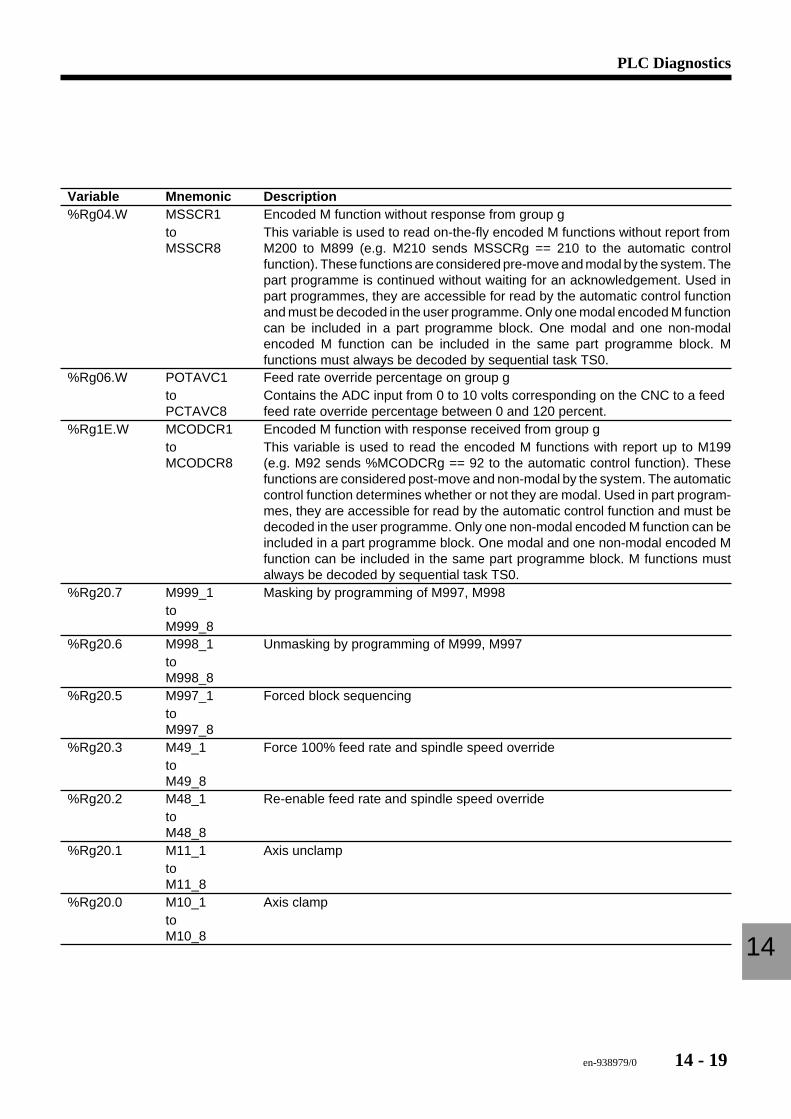
en-938979/0 14 - 19
PLC Diagnostics
14
Variable Mnemonic Description%Rg04.W MSSCR1 Encoded M function without response from group g
to This variable is used to read on-the-fly encoded M functions without report fromMSSCR8 M200 to M899 (e.g. M210 sends MSSCRg == 210 to the automatic control
function). These functions are considered pre-move and modal by the system. Thepart programme is continued without waiting for an acknowledgement. Used inpart programmes, they are accessible for read by the automatic control functionand must be decoded in the user programme. Only one modal encoded M functioncan be included in a part programme block. One modal and one non-modalencoded M function can be included in the same part programme block. Mfunctions must always be decoded by sequential task TS0.
%Rg06.W POTAVC1 Feed rate override percentage on group gto Contains the ADC input from 0 to 10 volts corresponding on the CNC to a feedPCTAVC8 feed rate override percentage between 0 and 120 percent.
%Rg1E.W MCODCR1 Encoded M function with response received from group gto This variable is used to read the encoded M functions with report up to M199MCODCR8 (e.g. M92 sends %MCODCRg == 92 to the automatic control function). These
functions are considered post-move and non-modal by the system. The automaticcontrol function determines whether or not they are modal. Used in part program-mes, they are accessible for read by the automatic control function and must bedecoded in the user programme. Only one non-modal encoded M function can beincluded in a part programme block. One modal and one non-modal encoded Mfunction can be included in the same part programme block. M functions mustalways be decoded by sequential task TS0.
%Rg20.7 M999_1 Masking by programming of M997, M998toM999_8
%Rg20.6 M998_1 Unmasking by programming of M999, M997toM998_8
%Rg20.5 M997_1 Forced block sequencingtoM997_8
%Rg20.3 M49_1 Force 100% feed rate and spindle speed overridetoM49_8
%Rg20.2 M48_1 Re-enable feed rate and spindle speed overridetoM48_8
%Rg20.1 M11_1 Axis unclamptoM11_8
%Rg20.0 M10_1 Axis clamptoM10_8
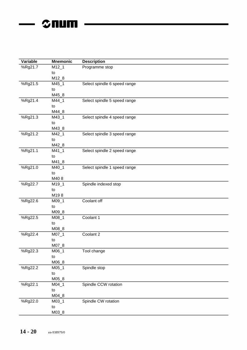
14 - 20 en-938979/0
Variable Mnemonic Description%Rg21.7 M12_1 Programme stop
toM12_8
%Rg21.5 M45_1 Select spindle 6 speed rangetoM45_8
%Rg21.4 M44_1 Select spindle 5 speed rangetoM44_8
%Rg21.3 M43_1 Select spindle 4 speed rangetoM43_8
%Rg21.2 M42_1 Select spindle 3 speed rangetoM42_8
%Rg21.1 M41_1 Select spindle 2 speed rangetoM41_8
%Rg21.0 M40_1 Select spindle 1 speed rangetoM40 8
%Rg22.7 M19_1 Spindle indexed stoptoM19 8
%Rg22.6 M09_1 Coolant offtoM09_8
%Rg22.5 M08_1 Coolant 1toM08_8
%Rg22.4 M07_1 Coolant 2toM07_8
%Rg22.3 M06_1 Tool changetoM06_8
%Rg22.2 M05_1 Spindle stoptoM05_8
%Rg22.1 M04_1 Spindle CCW rotationtoM04_8
%Rg22.0 M03_1 Spindle CW rotationtoM03_8
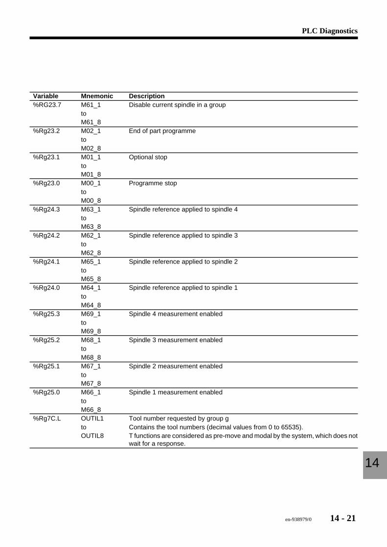
en-938979/0 14 - 21
PLC Diagnostics
14
Variable Mnemonic Description%RG23.7 M61_1 Disable current spindle in a group
toM61_8
%Rg23.2 M02_1 End of part programmetoM02_8
%Rg23.1 M01_1 Optional stoptoM01_8
%Rg23.0 M00_1 Programme stoptoM00_8
%Rg24.3 M63_1 Spindle reference applied to spindle 4toM63_8
%Rg24.2 M62_1 Spindle reference applied to spindle 3toM62_8
%Rg24.1 M65_1 Spindle reference applied to spindle 2toM65_8
%Rg24.0 M64_1 Spindle reference applied to spindle 1toM64_8
%Rg25.3 M69_1 Spindle 4 measurement enabledtoM69_8
%Rg25.2 M68_1 Spindle 3 measurement enabledtoM68_8
%Rg25.1 M67_1 Spindle 2 measurement enabledtoM67_8
%Rg25.0 M66_1 Spindle 1 measurement enabledtoM66_8
%Rg7C.L OUTIL1 Tool number requested by group gto Contains the tool numbers (decimal values from 0 to 65535).OUTIL8 T functions are considered as pre-move and modal by the system, which does not
wait for a response.
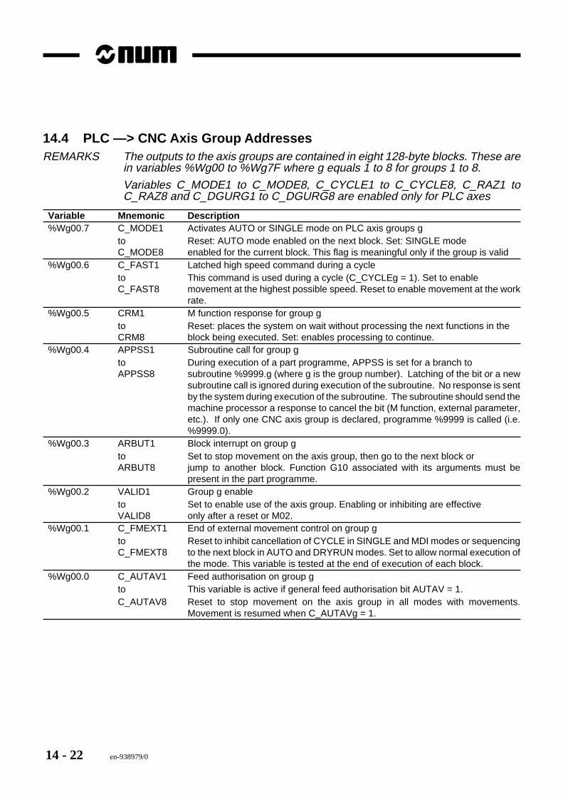
14 - 22 en-938979/0
14.4 PLC —> CNC Axis Group AddressesREMARKS The outputs to the axis groups are contained in eight 128-byte blocks. These are
in variables %Wg00 to %Wg7F where g equals 1 to 8 for groups 1 to 8.
Variables C_MODE1 to C_MODE8, C_CYCLE1 to C_CYCLE8, C_RAZ1 toC_RAZ8 and C_DGURG1 to C_DGURG8 are enabled only for PLC axes
Variable Mnemonic Description%Wg00.7 C_MODE1 Activates AUTO or SINGLE mode on PLC axis groups g
to Reset: AUTO mode enabled on the next block. Set: SINGLE modeC_MODE8 enabled for the current block. This flag is meaningful only if the group is valid
%Wg00.6 C_FAST1 Latched high speed command during a cycleto This command is used during a cycle (C_CYCLEg = 1). Set to enableC_FAST8 movement at the highest possible speed. Reset to enable movement at the work
rate.%Wg00.5 CRM1 M function response for group g
to Reset: places the system on wait without processing the next functions in theCRM8 block being executed. Set: enables processing to continue.
%Wg00.4 APPSS1 Subroutine call for group gto During execution of a part programme, APPSS is set for a branch toAPPSS8 subroutine %9999.g (where g is the group number). Latching of the bit or a new
subroutine call is ignored during execution of the subroutine. No response is sentby the system during execution of the subroutine. The subroutine should send themachine processor a response to cancel the bit (M function, external parameter,etc.). If only one CNC axis group is declared, programme %9999 is called (i.e.%9999.0).
%Wg00.3 ARBUT1 Block interrupt on group gto Set to stop movement on the axis group, then go to the next block orARBUT8 jump to another block. Function G10 associated with its arguments must be
present in the part programme.%Wg00.2 VALID1 Group g enable
to Set to enable use of the axis group. Enabling or inhibiting are effectiveVALID8 only after a reset or M02.
%Wg00.1 C_FMEXT1 End of external movement control on group gto Reset to inhibit cancellation of CYCLE in SINGLE and MDI modes or sequencingC_FMEXT8 to the next block in AUTO and DRYRUN modes. Set to allow normal execution of
the mode. This variable is tested at the end of execution of each block.%Wg00.0 C_AUTAV1 Feed authorisation on group g
to This variable is active if general feed authorisation bit AUTAV = 1.C_AUTAV8 Reset to stop movement on the axis group in all modes with movements.
Movement is resumed when C_AUTAVg = 1.
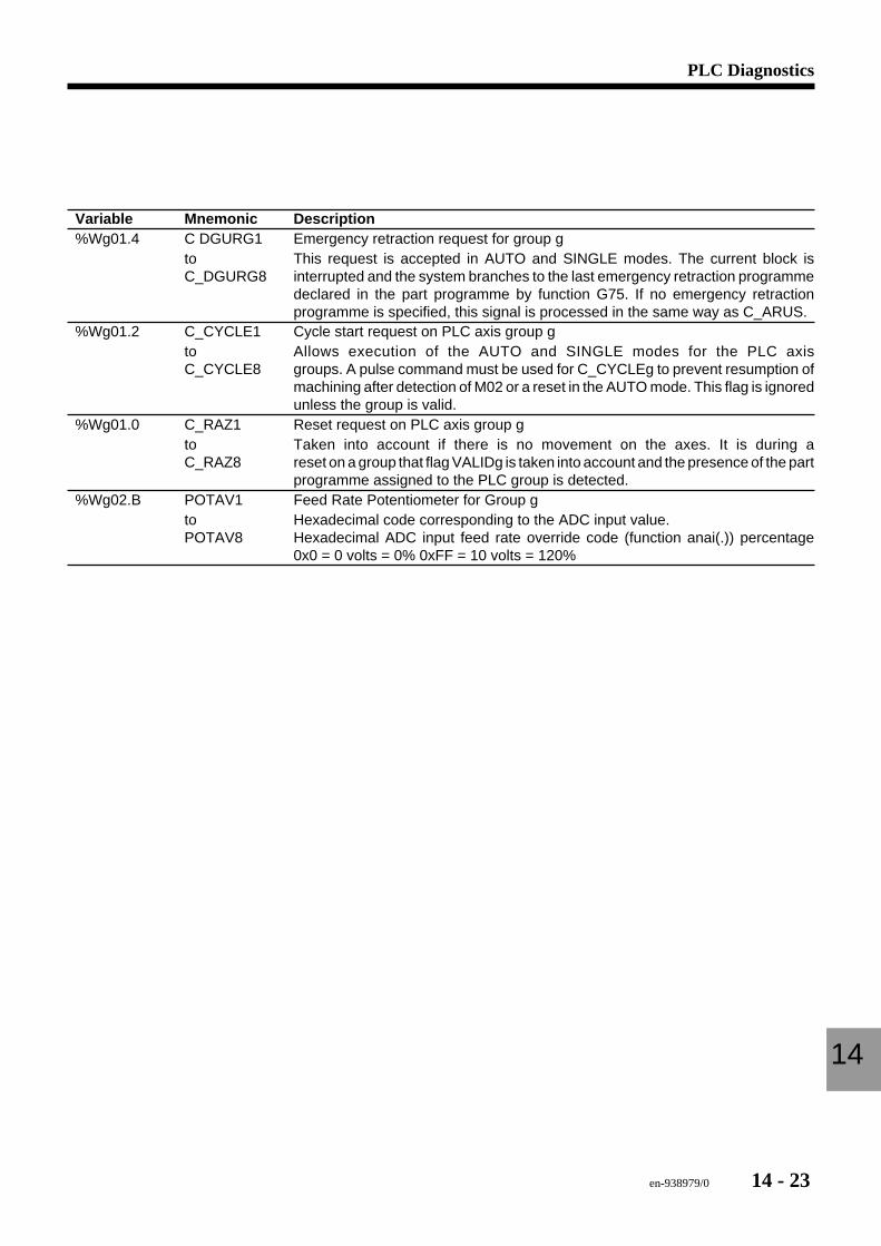
en-938979/0 14 - 23
PLC Diagnostics
14
Variable Mnemonic Description%Wg01.4 C DGURG1 Emergency retraction request for group g
to This request is accepted in AUTO and SINGLE modes. The current block isC_DGURG8 interrupted and the system branches to the last emergency retraction programme
declared in the part programme by function G75. If no emergency retractionprogramme is specified, this signal is processed in the same way as C_ARUS.
%Wg01.2 C_CYCLE1 Cycle start request on PLC axis group gto Allows execution of the AUTO and SINGLE modes for the PLC axisC_CYCLE8 groups. A pulse command must be used for C_CYCLEg to prevent resumption of
machining after detection of M02 or a reset in the AUTO mode. This flag is ignoredunless the group is valid.
%Wg01.0 C_RAZ1 Reset request on PLC axis group gto Taken into account if there is no movement on the axes. It is during aC_RAZ8 reset on a group that flag VALIDg is taken into account and the presence of the part
programme assigned to the PLC group is detected.%Wg02.B POTAV1 Feed Rate Potentiometer for Group g
to Hexadecimal code corresponding to the ADC input value.POTAV8 Hexadecimal ADC input feed rate override code (function anai(.)) percentage
0x0 = 0 volts = 0% 0xFF = 10 volts = 120%
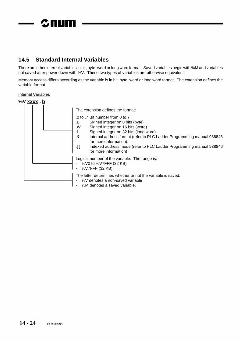
14 - 24 en-938979/0
14.5 Standard Internal VariablesThere are other internal variables in bit, byte, word or long word format. Saved variables begin with %M and variablesnot saved after power down with %V. These two types of variables are otherwise equivalent.
Memory access differs according as the variable is in bit, byte, word or long word format. The extension defines thevariable format.
Internal Variables
%V xxxx . b
The extension defines the format:
.0 to .7 Bit number from 0 to 7
.B Signed integer on 8 bits (byte)
.W Signed integer on 16 bits (word)
.L Signed integer on 32 bits (long word)
.& Internal address format (refer to PLC Ladder Programming manual 938846for more information).
.[ ] Indexed address mode (refer to PLC Ladder Programming manual 938846for more information)
Logical number of the variable. The range is:- %V0 to %V7FFF (32 KB)- %V7FFF (32 KB).
The letter determines whether or not the variable is saved:- %V denotes a non-saved variable- %M denotes a saved variable.
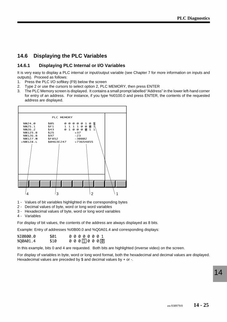
en-938979/0 14 - 25
PLC Diagnostics
14
14.6 Displaying the PLC Variables
14.6.1 Displaying PLC Internal or I/O Variables
It is very easy to display a PLC internal or input/output variable (see Chapter 7 for more information on inputs andoutputs). Proceed as follows:1. Press the PLC I/O softkey (F9) below the screen2. Type 2 or use the cursors to select option 2, PLC MEMORY, then press ENTER3. The PLC Memory screen is displayed. It contains a small prompt labelled “Address” in the lower left-hand corner
for entry of an address. For instance, if you type %I0100.0 and press ENTER, the contents of the requestedaddress are displayed.
4 3 2 1
PLC MEMORY
%W24.0 $05 0 0 0 0 0 1 0 1 %W25.1 $F1 1 1 1 1 0 0 0 1 %W26.2 $43 0 1 0 0 0 0 1 1 %W125.B $25 +37 %W126.B $97 -23 %W127.W $F852 -30802>%W128.L $0463E247 +73654855
1 - Values of bit variables highlighted in the corresponding bytes2 - Decimal values of byte, word or long word variables3 - Hexadecimal values of byte, word or long word variables4 - Variables
For display of bit values, the contents of the address are always displayed as 8 bits.
Example: Entry of addresses %I0B00.0 and %Q0A01.4 and corresponding displays:
%I0B00.0 $01 0 0 0 0 0 0 0 1%Q0A01.4 $10 0 0 0 1 0 0 0 0
In this example, bits 0 and 4 are requested. Both bits are highlighted (inverse video) on the screen.
For display of variables in byte, word or long word format, both the hexadecimal and decimal values are displayed.Hexadecimal values are preceded by $ and decimal values by + or -.
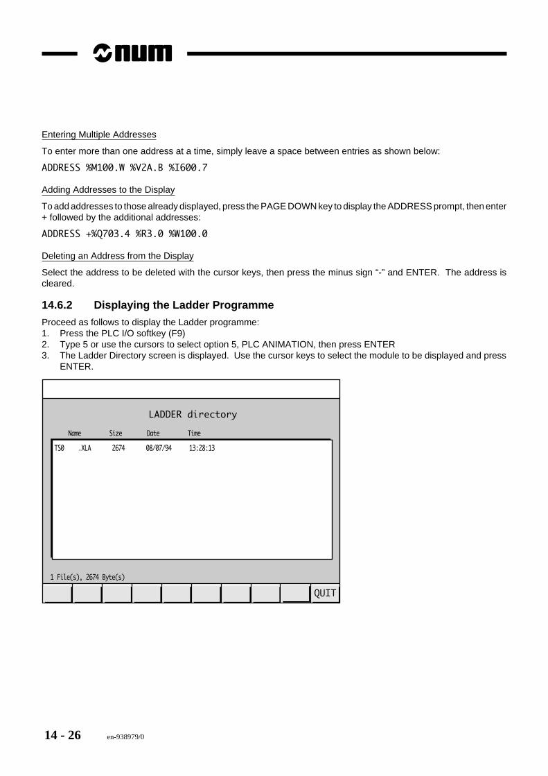
14 - 26 en-938979/0
Entering Multiple Addresses
To enter more than one address at a time, simply leave a space between entries as shown below:
ADDRESS %M100.W %V2A.B %I600.7
Adding Addresses to the Display
To add addresses to those already displayed, press the PAGE DOWN key to display the ADDRESS prompt, then enter+ followed by the additional addresses:
ADDRESS +%Q703.4 %R3.0 %W100.0
Deleting an Address from the Display
Select the address to be deleted with the cursor keys, then press the minus sign “-” and ENTER. The address iscleared.
14.6.2 Displaying the Ladder Programme
Proceed as follows to display the Ladder programme:1. Press the PLC I/O softkey (F9)2. Type 5 or use the cursors to select option 5, PLC ANIMATION, then press ENTER3. The Ladder Directory screen is displayed. Use the cursor keys to select the module to be displayed and press
ENTER.
LADDER directory
1 File(s), 2674 Byte(s)
Name Size Date Time
QUIT
TS0 .XLA 2674 08/07/94 13:28:13
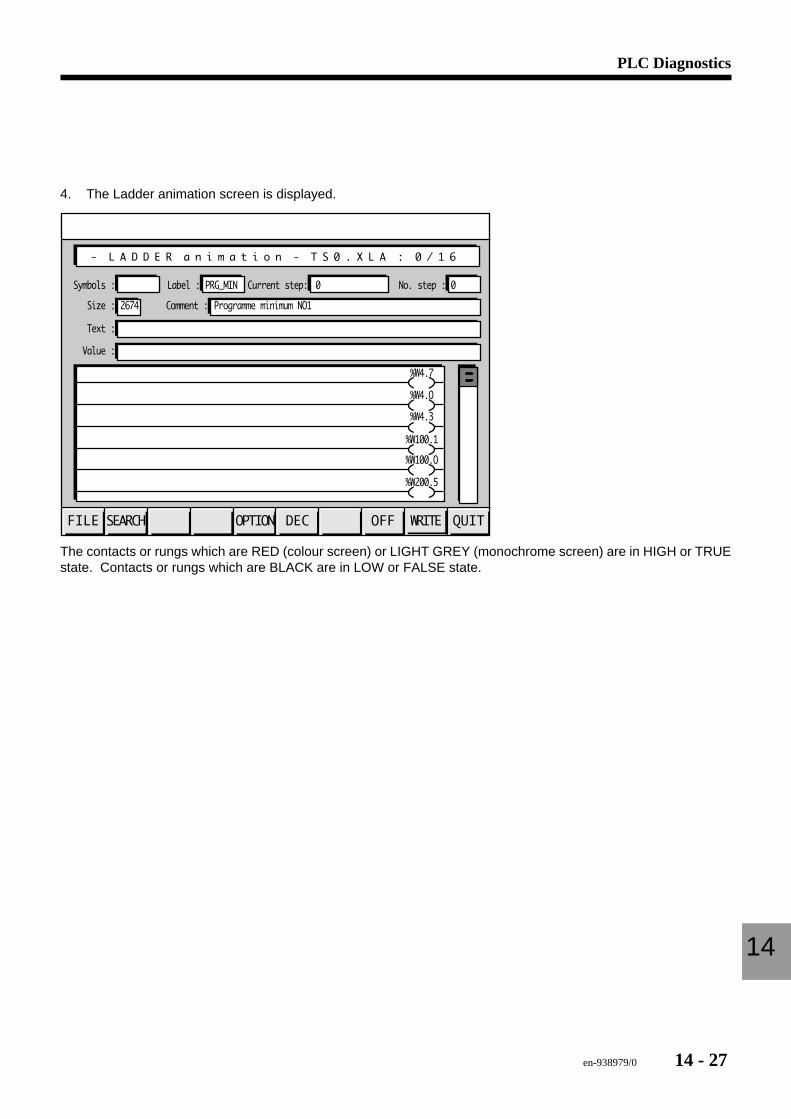
en-938979/0 14 - 27
PLC Diagnostics
14
4. The Ladder animation screen is displayed.
QUITWRITEOFFDECOPTIONSEARCHFILE
Symbols : Label : No. step :Current step:
Size : Comment : Programme minimum NO12674
Text :
Value :
- L A D D E R a n i m a t i o n - T S 0 . X L A : 0 / 1 6
0PRG_MIN 0
%W4.O
%W4.7
%W4.3
%W100.1
%W100.O
%W200.5
The contacts or rungs which are RED (colour screen) or LIGHT GREY (monochrome screen) are in HIGH or TRUEstate. Contacts or rungs which are BLACK are in LOW or FALSE state.
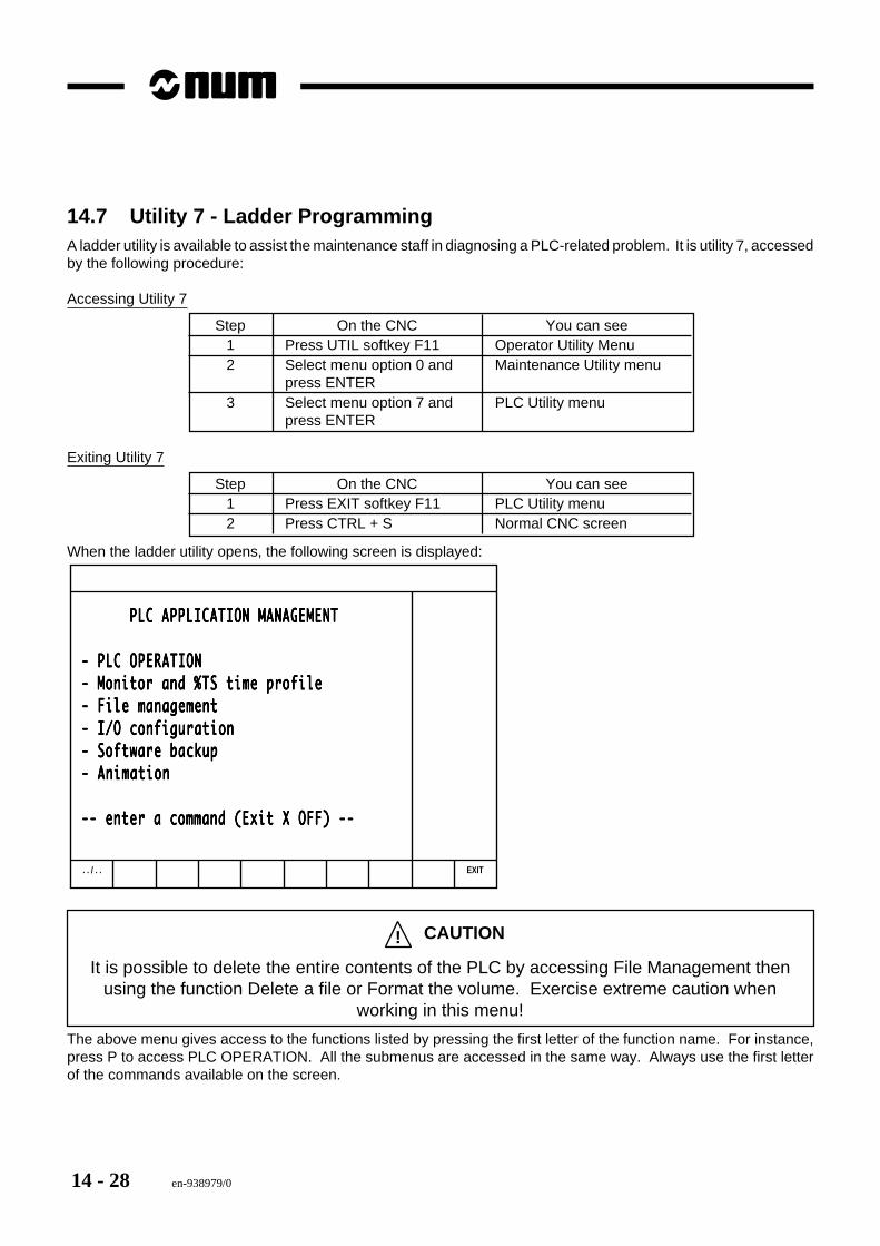
14 - 28 en-938979/0
14.7 Utility 7 - Ladder ProgrammingA ladder utility is available to assist the maintenance staff in diagnosing a PLC-related problem. It is utility 7, accessedby the following procedure:
Accessing Utility 7
Step On the CNC You can see1 Press UTIL softkey F11 Operator Utility Menu2 Select menu option 0 and Maintenance Utility menu
press ENTER3 Select menu option 7 and PLC Utility menu
press ENTER
Exiting Utility 7
Step On the CNC You can see1 Press EXIT softkey F11 PLC Utility menu2 Press CTRL + S Normal CNC screen
When the ladder utility opens, the following screen is displayed:
. . / . . EXIT
PLC APPLICATION MANAGEMENT PLC APPLICATION MANAGEMENT PLC APPLICATION MANAGEMENT PLC APPLICATION MANAGEMENT PLC APPLICATION MANAGEMENT
- PLC OPERATION- PLC OPERATION- PLC OPERATION- PLC OPERATION- PLC OPERATION- Monitor and %TS time profile- Monitor and %TS time profile- Monitor and %TS time profile- Monitor and %TS time profile- Monitor and %TS time profile- File management- File management- File management- File management- File management- I/O configuration- I/O configuration- I/O configuration- I/O configuration- I/O configuration- Software backup- Software backup- Software backup- Software backup- Software backup- Animation- Animation- Animation- Animation- Animation
-- enter a command (Exit X OFF) ---- enter a command (Exit X OFF) ---- enter a command (Exit X OFF) ---- enter a command (Exit X OFF) ---- enter a command (Exit X OFF) --
! CAUTION
It is possible to delete the entire contents of the PLC by accessing File Management thenusing the function Delete a file or Format the volume. Exercise extreme caution when
working in this menu!
The above menu gives access to the functions listed by pressing the first letter of the function name. For instance,press P to access PLC OPERATION. All the submenus are accessed in the same way. Always use the first letterof the commands available on the screen.
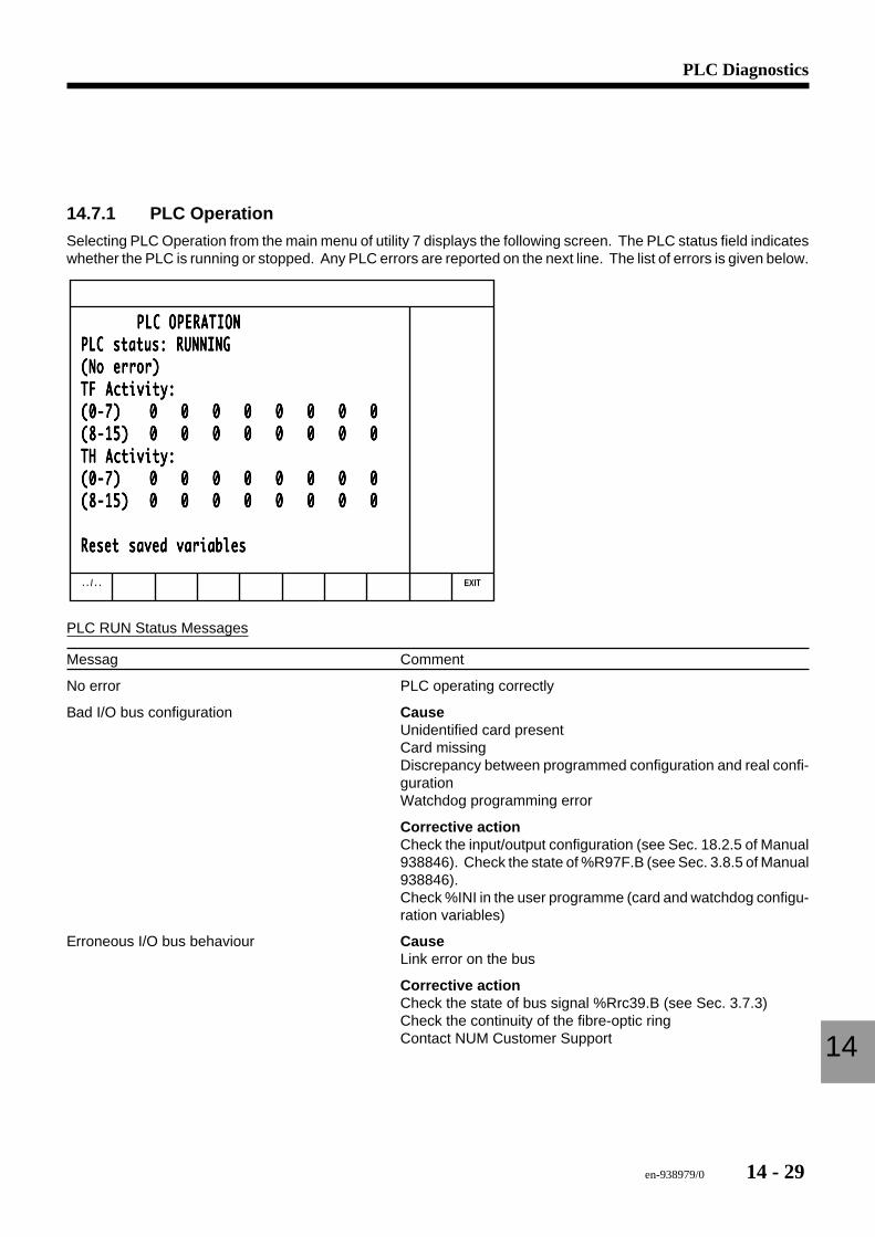
en-938979/0 14 - 29
PLC Diagnostics
14
14.7.1 PLC Operation
Selecting PLC Operation from the main menu of utility 7 displays the following screen. The PLC status field indicateswhether the PLC is running or stopped. Any PLC errors are reported on the next line. The list of errors is given below.
. . / . . EXIT
PLC OPERATION PLC OPERATION PLC OPERATION PLC OPERATION PLC OPERATIONPLC status: RUNNINGPLC status: RUNNINGPLC status: RUNNINGPLC status: RUNNINGPLC status: RUNNING(No error)(No error)(No error)(No error)(No error)TF Activity:TF Activity:TF Activity:TF Activity:TF Activity:(0-7)(0-7)(0-7)(0-7)(0-7) 0 0 0 0 0 0 0 00 0 0 0 0 0 0 00 0 0 0 0 0 0 00 0 0 0 0 0 0 00 0 0 0 0 0 0 0(8-15)(8-15)(8-15)(8-15)(8-15) 0 0 0 0 0 0 0 00 0 0 0 0 0 0 00 0 0 0 0 0 0 00 0 0 0 0 0 0 00 0 0 0 0 0 0 0TH Activity:TH Activity:TH Activity:TH Activity:TH Activity:(0-7)(0-7)(0-7)(0-7)(0-7) 0 0 0 0 0 0 0 00 0 0 0 0 0 0 00 0 0 0 0 0 0 00 0 0 0 0 0 0 00 0 0 0 0 0 0 0(8-15)(8-15)(8-15)(8-15)(8-15) 0 0 0 0 0 0 0 00 0 0 0 0 0 0 00 0 0 0 0 0 0 00 0 0 0 0 0 0 00 0 0 0 0 0 0 0
Reset saved variablesReset saved variablesReset saved variablesReset saved variablesReset saved variables
PLC RUN Status Messages
Messag Comment
No error PLC operating correctly
Bad I/O bus configuration CauseUnidentified card presentCard missingDiscrepancy between programmed configuration and real confi-gurationWatchdog programming error
Corrective actionCheck the input/output configuration (see Sec. 18.2.5 of Manual938846). Check the state of %R97F.B (see Sec. 3.8.5 of Manual938846).Check %INI in the user programme (card and watchdog configu-ration variables)
Erroneous I/O bus behaviour CauseLink error on the bus
Corrective actionCheck the state of bus signal %Rrc39.B (see Sec. 3.7.3)Check the continuity of the fibre-optic ringContact NUM Customer Support
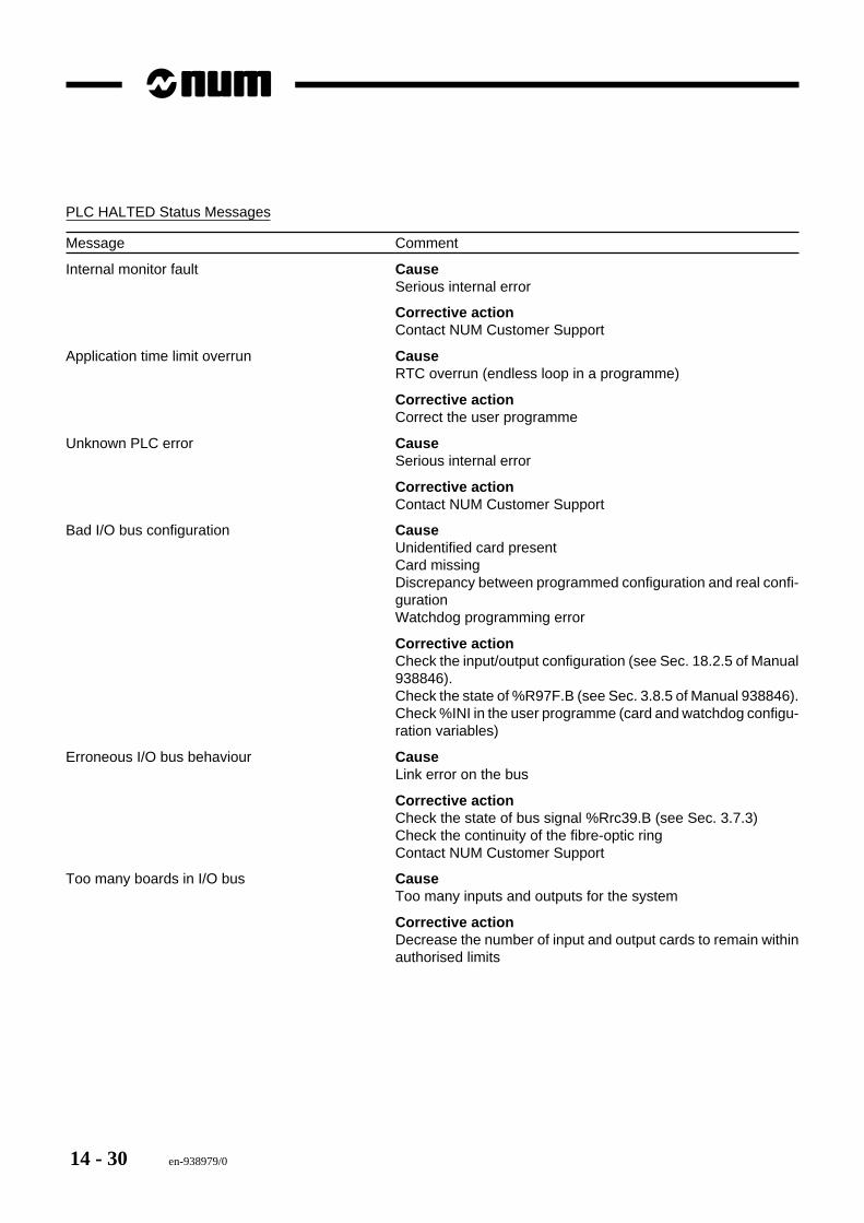
14 - 30 en-938979/0
PLC HALTED Status Messages
Message Comment
Internal monitor fault CauseSerious internal error
Corrective actionContact NUM Customer Support
Application time limit overrun CauseRTC overrun (endless loop in a programme)
Corrective actionCorrect the user programme
Unknown PLC error CauseSerious internal error
Corrective actionContact NUM Customer Support
Bad I/O bus configuration CauseUnidentified card presentCard missingDiscrepancy between programmed configuration and real confi-gurationWatchdog programming error
Corrective actionCheck the input/output configuration (see Sec. 18.2.5 of Manual938846).Check the state of %R97F.B (see Sec. 3.8.5 of Manual 938846).Check %INI in the user programme (card and watchdog configu-ration variables)
Erroneous I/O bus behaviour CauseLink error on the bus
Corrective actionCheck the state of bus signal %Rrc39.B (see Sec. 3.7.3)Check the continuity of the fibre-optic ringContact NUM Customer Support
Too many boards in I/O bus CauseToo many inputs and outputs for the system
Corrective actionDecrease the number of input and output cards to remain withinauthorised limits
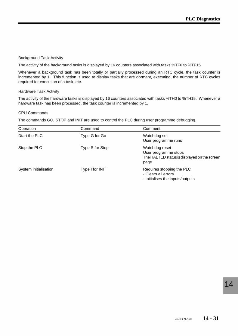
en-938979/0 14 - 31
PLC Diagnostics
14
Background Task Activity
The activity of the background tasks is displayed by 16 counters associated with tasks %TF0 to %TF15.
Whenever a background task has been totally or partially processed during an RTC cycle, the task counter isincremented by 1. This function is used to display tasks that are dormant, executing, the number of RTC cyclesrequired for execution of a task, etc.
Hardware Task Activity
The activity of the hardware tasks is displayed by 16 counters associated with tasks %TH0 to %TH15. Whenever ahardware task has been processed, the task counter is incremented by 1.
CPU Commands
The commands GO, STOP and INIT are used to control the PLC during user programme debugging.
Operation Command Comment
Dtart the PLC Type G for Go Watchdog setUser programme runs
Stop the PLC Type S for Stop Watchdog resetUser programme stopsThe HALTED status is displayed on the screenpage
System initialisation Type I for INIT Requires stopping the PLC- Clears all errors- Initialises the inputs/outputs
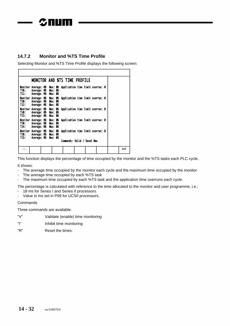
14 - 32 en-938979/0
14.7.2 Monitor and %TS Time Profile
Selecting Monitor and %TS Time Profile displays the following screen:
. . / . . EXIT
MONITOR AND %TS TIME PROFILE MONITOR AND %TS TIME PROFILE MONITOR AND %TS TIME PROFILE MONITOR AND %TS TIME PROFILE MONITOR AND %TS TIME PROFILEMonitorMonitorMonitorMonitorMonitor Average: 0% Max: 0%Average: 0% Max: 0%Average: 0% Max: 0%Average: 0% Max: 0%Average: 0% Max: 0% Application time limit overrun: 0Application time limit overrun: 0Application time limit overrun: 0Application time limit overrun: 0Application time limit overrun: 0TS0:TS0:TS0:TS0:TS0: Average: 0% Max: 0%Average: 0% Max: 0%Average: 0% Max: 0%Average: 0% Max: 0%Average: 0% Max: 0%TS1:TS1:TS1:TS1:TS1: Average: 0% Max: 0%Average: 0% Max: 0%Average: 0% Max: 0%Average: 0% Max: 0%Average: 0% Max: 0%MonitorMonitorMonitorMonitorMonitor Average: 0% Max: 0%Average: 0% Max: 0%Average: 0% Max: 0%Average: 0% Max: 0%Average: 0% Max: 0% Application time limit overrun: 0Application time limit overrun: 0Application time limit overrun: 0Application time limit overrun: 0Application time limit overrun: 0TS0:TS0:TS0:TS0:TS0: Average: 0% Max: 0%Average: 0% Max: 0%Average: 0% Max: 0%Average: 0% Max: 0%Average: 0% Max: 0%TS2:TS2:TS2:TS2:TS2: Average: 0% Max: 0%Average: 0% Max: 0%Average: 0% Max: 0%Average: 0% Max: 0%Average: 0% Max: 0%MonitorMonitorMonitorMonitorMonitor Average: 0% Max: 0%Average: 0% Max: 0%Average: 0% Max: 0%Average: 0% Max: 0%Average: 0% Max: 0% Application time limit overrun: 0Application time limit overrun: 0Application time limit overrun: 0Application time limit overrun: 0Application time limit overrun: 0TS0:TS0:TS0:TS0:TS0: Average: 0% Max: 0%Average: 0% Max: 0%Average: 0% Max: 0%Average: 0% Max: 0%Average: 0% Max: 0%TS3:TS3:TS3:TS3:TS3: Average: 0% Max: 0%Average: 0% Max: 0%Average: 0% Max: 0%Average: 0% Max: 0%Average: 0% Max: 0%MonitorMonitorMonitorMonitorMonitor Average: 0% Max: 0%Average: 0% Max: 0%Average: 0% Max: 0%Average: 0% Max: 0%Average: 0% Max: 0% Application time limit overrun: 0Application time limit overrun: 0Application time limit overrun: 0Application time limit overrun: 0Application time limit overrun: 0TS0:TS0:TS0:TS0:TS0: Average: 0% Max: 0%Average: 0% Max: 0%Average: 0% Max: 0%Average: 0% Max: 0%Average: 0% Max: 0%TS4:TS4:TS4:TS4:TS4: Average: 0% Max: 0%Average: 0% Max: 0%Average: 0% Max: 0%Average: 0% Max: 0%Average: 0% Max: 0%MonitorMonitorMonitorMonitorMonitor Average: 0% Max: 0%Average: 0% Max: 0%Average: 0% Max: 0%Average: 0% Max: 0%Average: 0% Max: 0% Application time limit overrun: 0Application time limit overrun: 0Application time limit overrun: 0Application time limit overrun: 0Application time limit overrun: 0TS0:TS0:TS0:TS0:TS0: Average: 0% Max: 0%Average: 0% Max: 0%Average: 0% Max: 0%Average: 0% Max: 0%Average: 0% Max: 0%TS5:TS5:TS5:TS5:TS5: Average: 0% Max: 0%Average: 0% Max: 0%Average: 0% Max: 0%Average: 0% Max: 0%Average: 0% Max: 0%
Commands: Valid / Reset MaxCommands: Valid / Reset MaxCommands: Valid / Reset MaxCommands: Valid / Reset MaxCommands: Valid / Reset Max
This function displays the percentage of time occupied by the monitor and the %TS tasks each PLC cycle.
It shows:- The average time occupied by the monitor each cycle and the maximum time occupied by the monitor- The average time occupied by each %TS task- The maximum time occupied by each %TS task and the application time overruns each cycle.
The percentage is calculated with reference to the time allocated to the monitor and user programme, i.e.:- 18 ms for Series I and Series II processors- Value in ms set in P99 for UCSII processors.
Commands
Three commands are available:
"V" Validate (enable) time monitoring
"I" Inhibit time monitoring
"R" Reset the times.
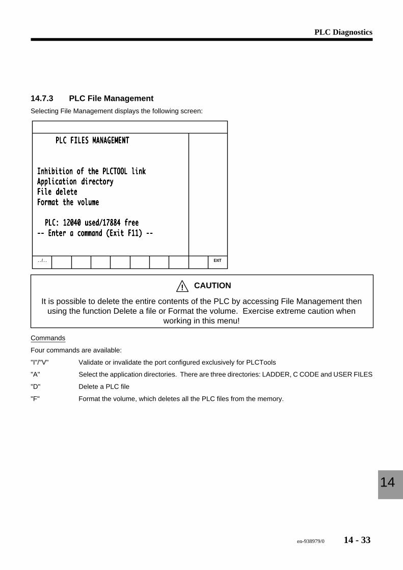
en-938979/0 14 - 33
PLC Diagnostics
14
14.7.3 PLC File Management
Selecting File Management displays the following screen:
. . / . . EXIT
PLC FILES MANAGEMENT PLC FILES MANAGEMENT PLC FILES MANAGEMENT PLC FILES MANAGEMENT PLC FILES MANAGEMENT
Inhibition of the PLCTOOL linkInhibition of the PLCTOOL linkInhibition of the PLCTOOL linkInhibition of the PLCTOOL linkInhibition of the PLCTOOL linkApplication directoryApplication directoryApplication directoryApplication directoryApplication directoryFile deleteFile deleteFile deleteFile deleteFile deleteFormat the volumeFormat the volumeFormat the volumeFormat the volumeFormat the volume
PLC: 12040 used/17884 free PLC: 12040 used/17884 free PLC: 12040 used/17884 free PLC: 12040 used/17884 free PLC: 12040 used/17884 free-- Enter a command (Exit F11) ---- Enter a command (Exit F11) ---- Enter a command (Exit F11) ---- Enter a command (Exit F11) ---- Enter a command (Exit F11) --
! CAUTION
It is possible to delete the entire contents of the PLC by accessing File Management thenusing the function Delete a file or Format the volume. Exercise extreme caution when
working in this menu!
Commands
Four commands are available:
"I"/"V" Validate or invalidate the port configured exclusively for PLCTools
"A" Select the application directories. There are three directories: LADDER, C CODE and USER FILES
"D" Delete a PLC file
"F" Format the volume, which deletes all the PLC files from the memory.
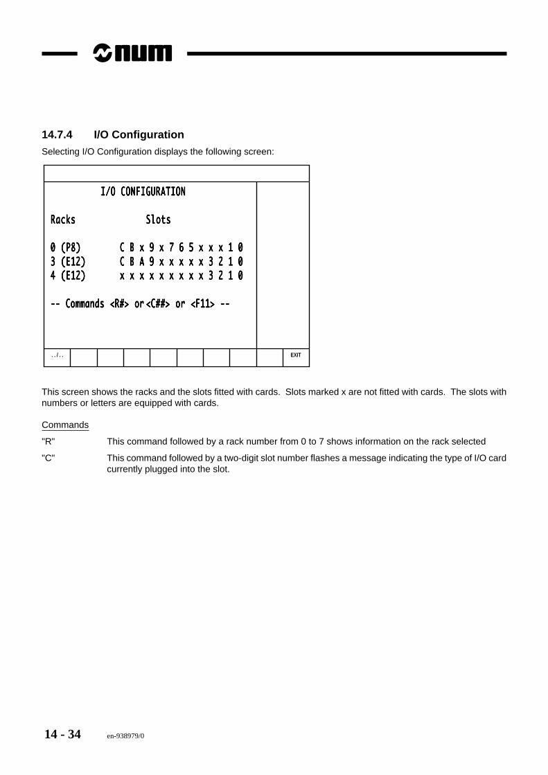
14 - 34 en-938979/0
14.7.4 I/O ConfigurationSelecting I/O Configuration displays the following screen:
. . / . . EXIT
I/O CONFIGURATION I/O CONFIGURATION I/O CONFIGURATION I/O CONFIGURATION I/O CONFIGURATION
RacksRacksRacksRacksRacks SlotsSlotsSlotsSlotsSlots
0 (P8)0 (P8)0 (P8)0 (P8)0 (P8) C B x 9 x 7 6 5 x x x 1 0C B x 9 x 7 6 5 x x x 1 0C B x 9 x 7 6 5 x x x 1 0C B x 9 x 7 6 5 x x x 1 0C B x 9 x 7 6 5 x x x 1 03 (E12)3 (E12)3 (E12)3 (E12)3 (E12) C B A 9 x x x x x 3 2 1 0C B A 9 x x x x x 3 2 1 0C B A 9 x x x x x 3 2 1 0C B A 9 x x x x x 3 2 1 0C B A 9 x x x x x 3 2 1 04 (E12)4 (E12)4 (E12)4 (E12)4 (E12) x x x x x x x x x 3 2 1 0x x x x x x x x x 3 2 1 0x x x x x x x x x 3 2 1 0x x x x x x x x x 3 2 1 0x x x x x x x x x 3 2 1 0
-- Commands <R#> or-- Commands <R#> or-- Commands <R#> or-- Commands <R#> or-- Commands <R#> or <C##> or <F11> --<C##> or <F11> --<C##> or <F11> --<C##> or <F11> --<C##> or <F11> --
This screen shows the racks and the slots fitted with cards. Slots marked x are not fitted with cards. The slots withnumbers or letters are equipped with cards.
Commands
"R" This command followed by a rack number from 0 to 7 shows information on the rack selected
"C" This command followed by a two-digit slot number flashes a message indicating the type of I/O cardcurrently plugged into the slot.
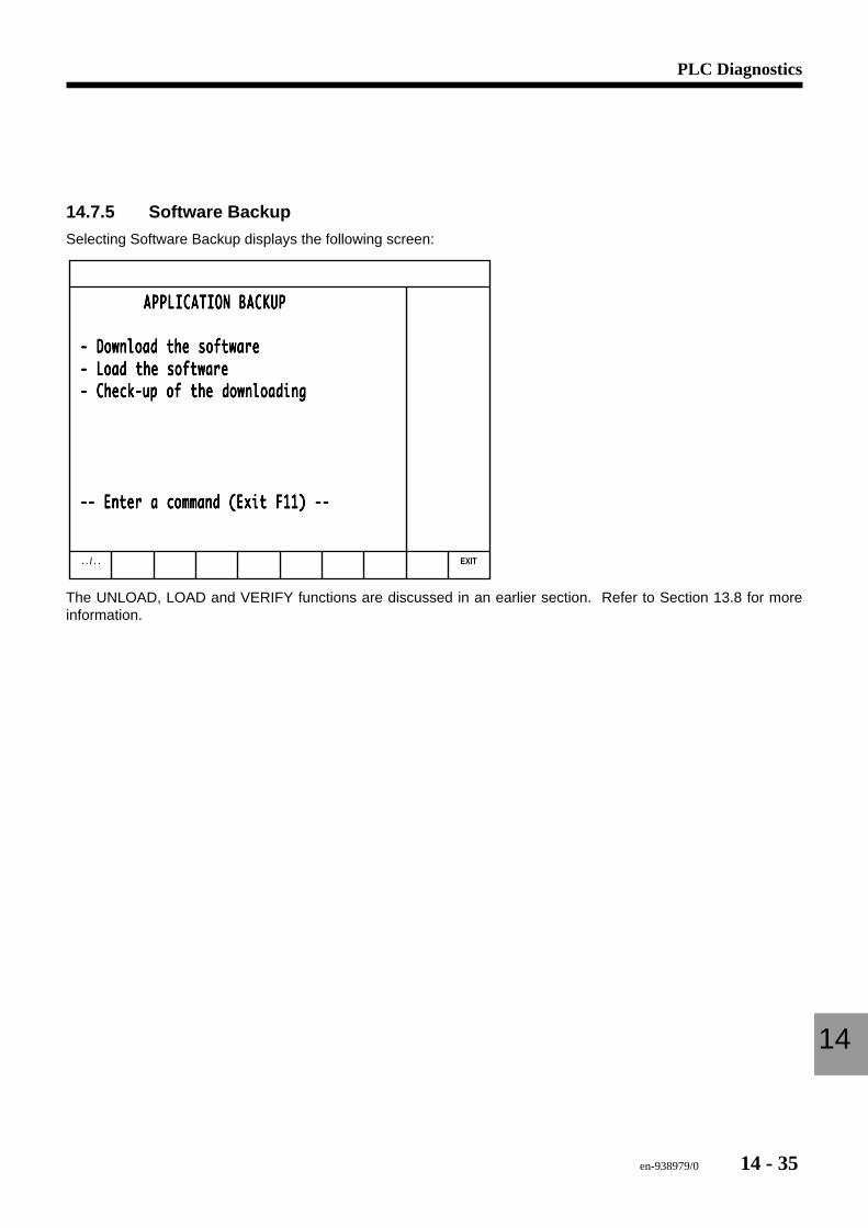
en-938979/0 14 - 35
PLC Diagnostics
14
14.7.5 Software Backup
Selecting Software Backup displays the following screen:
. . / . . EXIT
APPLICATION BACKUP APPLICATION BACKUP APPLICATION BACKUP APPLICATION BACKUP APPLICATION BACKUP
- Download the software- Download the software- Download the software- Download the software- Download the software- Load the software- Load the software- Load the software- Load the software- Load the software- Check-up of the downloading- Check-up of the downloading- Check-up of the downloading- Check-up of the downloading- Check-up of the downloading
-- Enter a command (Exit F11) ---- Enter a command (Exit F11) ---- Enter a command (Exit F11) ---- Enter a command (Exit F11) ---- Enter a command (Exit F11) --
The UNLOAD, LOAD and VERIFY functions are discussed in an earlier section. Refer to Section 13.8 for moreinformation.

14 - 36 en-938979/0
en-938979/0 15 - 1
Machine Parameters
15
15 Machine Parameters
15.1 List of Parameters 15 - 3
15.2 Utility 5 - Machine Setup Data 15 - 6
15.3 Often Accessed Machine Parameters 15 - 815.3.1 P16 Home Switch Position in Machine
Dimensions 15 - 815.3.2 P18 Reversal Error 15 - 815.3.3 P42 Spindle Origins 15 - 9

15 - 2 en-938979/0
en-938979/0 15 - 3
Machine Parameters
15NOTICE
The information presented below is in condensed format. For more detailed information,please refer to the Parameter Manual 938818.
15.1 List of ParametersParameter Category DescriptionP0 Axis declaration Displayed axesP1 Axis declaration Modulo and limited excursion rotary axesP2 Axis declaration Measured axesP3 Axis declaration Servo-controlled and interpolated axesP4 Axis declaration Axes programmed by diameter
Internal system measurementP5 Axis declaration Axis group machine configuration
Lathe or milling machine groupsFront/Rear turrets
P6 Spindles Number of controlled spindlesSpindle typeSpindle assignments to axis groups
P7 Miscellaneous Initialisation in inches or metric unitsDirection of automatic spindle searchTransmission of T and M functions to the machine processor in SEARCH andTEST modesForcing of T functionsInteraxis calibration table enable Initialisation in G94 or G95Forcing of manual modeHoming selectionSubroutine call on resetFeed stop with rigid tappingSpeed variation with gradual acceleration
P8 Axis declaration Axes with clampsP9 Axis declaration Axis assignment to groupsP10 Measurements Axis measurement directionP11 Measurements Axis measurement conversion coefficientP12 Measurements Direction of handwheel measurementP13 Measurements Handwheel measurement conversion coefficientP14 Axis declaration HandwheelsP15 Axis travel Direction of homing
Switch status testP16 Axis travel Reference switch position in machine dimensionsP17 Axis travel Axis travel limitP18 Axis travel Reversal error compensationP19 Servo-control Very high speed machiningP20 Servo-control Direction of axis speed referenceP21 Servo-control Servo-system loop gain coefficientP22 Servo-control In-position windowP23 Servo-control Maximum following errorP24 Servo-control Synchronised axis control
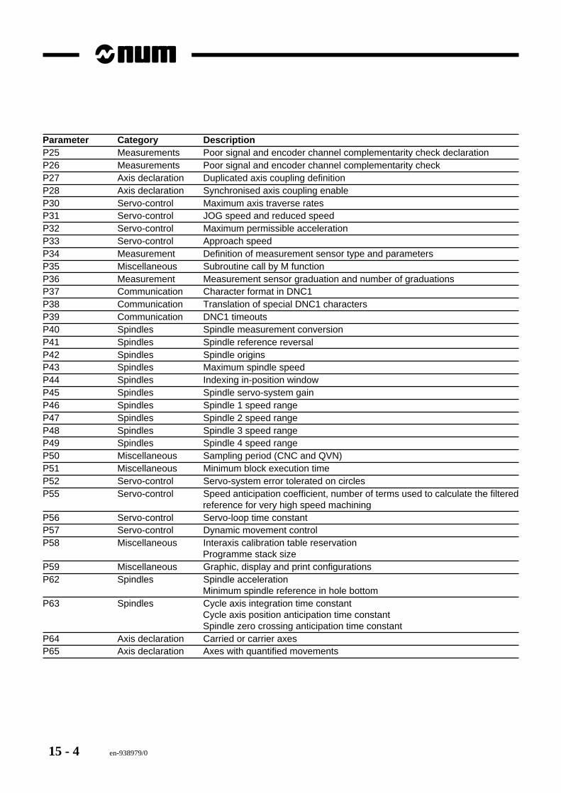
15 - 4 en-938979/0
Parameter Category DescriptionP25 Measurements Poor signal and encoder channel complementarity check declarationP26 Measurements Poor signal and encoder channel complementarity checkP27 Axis declaration Duplicated axis coupling definitionP28 Axis declaration Synchronised axis coupling enableP30 Servo-control Maximum axis traverse ratesP31 Servo-control JOG speed and reduced speedP32 Servo-control Maximum permissible accelerationP33 Servo-control Approach speedP34 Measurement Definition of measurement sensor type and parametersP35 Miscellaneous Subroutine call by M functionP36 Measurement Measurement sensor graduation and number of graduationsP37 Communication Character format in DNC1P38 Communication Translation of special DNC1 charactersP39 Communication DNC1 timeoutsP40 Spindles Spindle measurement conversionP41 Spindles Spindle reference reversalP42 Spindles Spindle originsP43 Spindles Maximum spindle speedP44 Spindles Indexing in-position windowP45 Spindles Spindle servo-system gainP46 Spindles Spindle 1 speed rangeP47 Spindles Spindle 2 speed rangeP48 Spindles Spindle 3 speed rangeP49 Spindles Spindle 4 speed rangeP50 Miscellaneous Sampling period (CNC and QVN)P51 Miscellaneous Minimum block execution timeP52 Servo-control Servo-system error tolerated on circlesP55 Servo-control Speed anticipation coefficient, number of terms used to calculate the filtered
reference for very high speed machiningP56 Servo-control Servo-loop time constantP57 Servo-control Dynamic movement controlP58 Miscellaneous Interaxis calibration table reservation
Programme stack sizeP59 Miscellaneous Graphic, display and print configurationsP62 Spindles Spindle acceleration
Minimum spindle reference in hole bottomP63 Spindles Cycle axis integration time constant
Cycle axis position anticipation time constantSpindle zero crossing anticipation time constant
P64 Axis declaration Carried or carrier axesP65 Axis declaration Axes with quantified movements
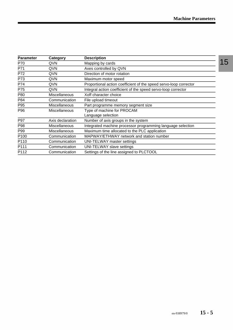
en-938979/0 15 - 5
Machine Parameters
15Parameter Category DescriptionP70 QVN Mapping by cardsP71 QVN Axes controlled by QVNP72 QVN Direction of motor rotationP73 QVN Maximum motor speedP74 QVN Proportional action coefficient of the speed servo-loop correctorP75 QVN Integral action coefficient of the speed servo-loop correctorP80 Miscellaneous Xoff character choiceP84 Communication File upload timeoutP95 Miscellaneous Part programme memory segment sizeP96 Miscellaneous Type of machine for PROCAM
Language selectionP97 Axis declaration Number of axis groups in the systemP98 Miscellaneous Integrated machine processor programming language selectionP99 Miscellaneous Maximum time allocated to the PLC applicationP100 Communication MAPWAY/ETHWAY network and station numberP110 Communication UNI-TELWAY master settingsP111 Communication UNI-TELWAY slave settingsP112 Communication Settings of the line assigned to PLCTOOL
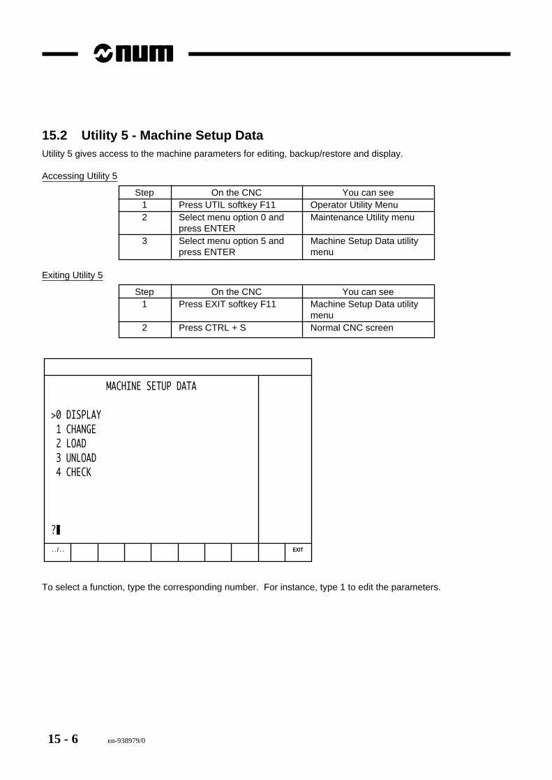
15 - 6 en-938979/0
15.2 Utility 5 - Machine Setup DataUtility 5 gives access to the machine parameters for editing, backup/restore and display.
Accessing Utility 5
Step On the CNC You can see1 Press UTIL softkey F11 Operator Utility Menu2 Select menu option 0 and Maintenance Utility menu
press ENTER3 Select menu option 5 and Machine Setup Data utility
press ENTER menu
Exiting Utility 5
Step On the CNC You can see1 Press EXIT softkey F11 Machine Setup Data utility
menu2 Press CTRL + S Normal CNC screen
. . / . . EXIT
MACHINE SETUP DATA
>0 DISPLAY 1 CHANGE 2 LOAD 3 UNLOAD 4 CHECK
?
To select a function, type the corresponding number. For instance, type 1 to edit the parameters.
en-938979/0 15 - 7
Machine Parameters
15Moving from Parameter to Parameter
Use one of the following commands to move from one parameter to another:
"PgDn" Next parameter
"Pxx" Parameter number
Moving up and down N words within a Parameter
Down arrow Move down
"Nxx" Word number
Editing a Word
1. Place the cursor on the word to be edited (sign > opposite the word)2. Type #3. Press ENTER4. The line is displayed in the command line at the bottom of the screen5. Enter the new value and confirm by pressing ENTER.
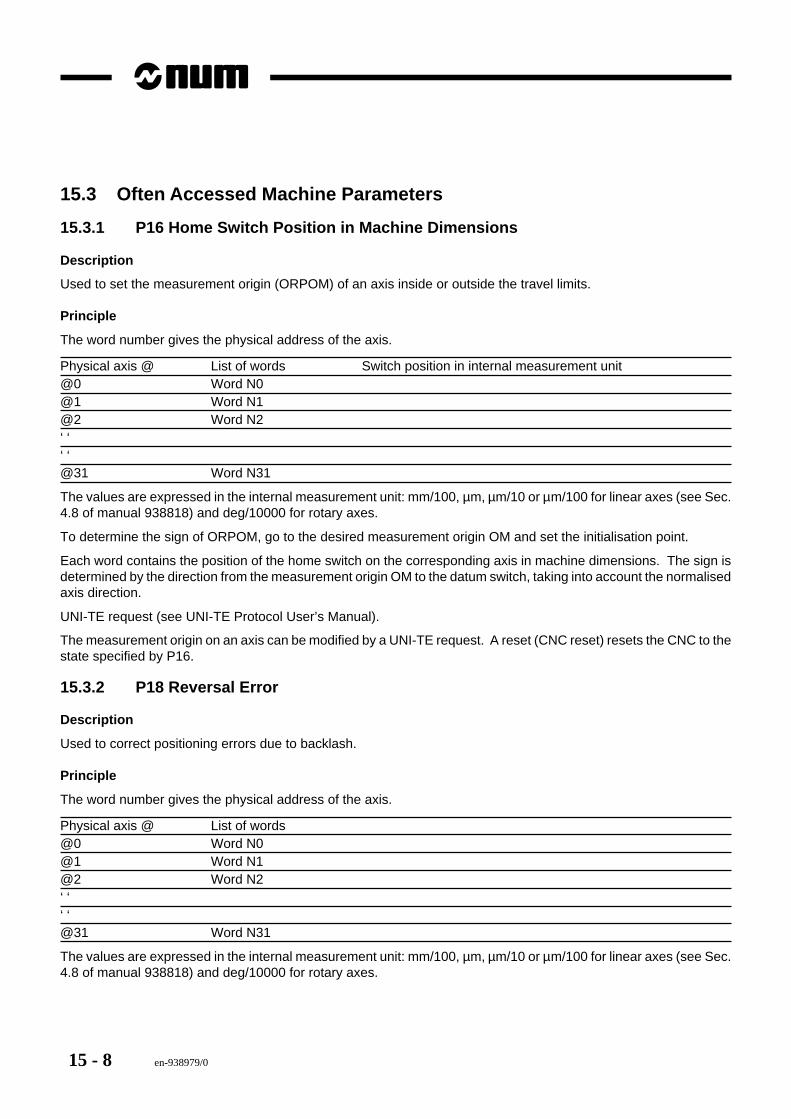
15 - 8 en-938979/0
15.3 Often Accessed Machine Parameters
15.3.1 P16 Home Switch Position in Machine Dimensions
Description
Used to set the measurement origin (ORPOM) of an axis inside or outside the travel limits.
Principle
The word number gives the physical address of the axis.
Physical axis @ List of words Switch position in internal measurement unit@0 Word N0@1 Word N1@2 Word N2‘ ‘‘ ‘@31 Word N31
The values are expressed in the internal measurement unit: mm/100, µm, µm/10 or µm/100 for linear axes (see Sec.4.8 of manual 938818) and deg/10000 for rotary axes.
To determine the sign of ORPOM, go to the desired measurement origin OM and set the initialisation point.
Each word contains the position of the home switch on the corresponding axis in machine dimensions. The sign isdetermined by the direction from the measurement origin OM to the datum switch, taking into account the normalisedaxis direction.
UNI-TE request (see UNI-TE Protocol User’s Manual).
The measurement origin on an axis can be modified by a UNI-TE request. A reset (CNC reset) resets the CNC to thestate specified by P16.
15.3.2 P18 Reversal Error
Description
Used to correct positioning errors due to backlash.
Principle
The word number gives the physical address of the axis.
Physical axis @ List of words@0 Word N0@1 Word N1@2 Word N2‘ ‘‘ ‘@31 Word N31
The values are expressed in the internal measurement unit: mm/100, µm, µm/10 or µm/100 for linear axes (see Sec.4.8 of manual 938818) and deg/10000 for rotary axes.
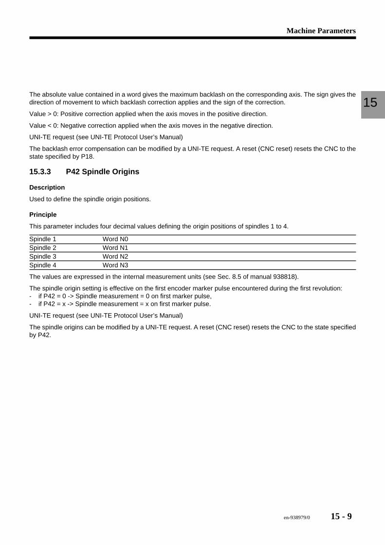
en-938979/0 15 - 9
Machine Parameters
15The absolute value contained in a word gives the maximum backlash on the corresponding axis. The sign gives thedirection of movement to which backlash correction applies and the sign of the correction.
Value > 0: Positive correction applied when the axis moves in the positive direction.
Value < 0: Negative correction applied when the axis moves in the negative direction.
UNI-TE request (see UNI-TE Protocol User’s Manual)
The backlash error compensation can be modified by a UNI-TE request. A reset (CNC reset) resets the CNC to thestate specified by P18.
15.3.3 P42 Spindle Origins
Description
Used to define the spindle origin positions.
Principle
This parameter includes four decimal values defining the origin positions of spindles 1 to 4.
Spindle 1 Word N0Spindle 2 Word N1Spindle 3 Word N2Spindle 4 Word N3
The values are expressed in the internal measurement units (see Sec. 8.5 of manual 938818).
The spindle origin setting is effective on the first encoder marker pulse encountered during the first revolution:- if P42 = 0 -> Spindle measurement = 0 on first marker pulse,- if P42 = x -> Spindle measurement = x on first marker pulse.
UNI-TE request (see UNI-TE Protocol User’s Manual)
The spindle origins can be modified by a UNI-TE request. A reset (CNC reset) resets the CNC to the state specifiedby P42.

15 - 10 en-938979/0
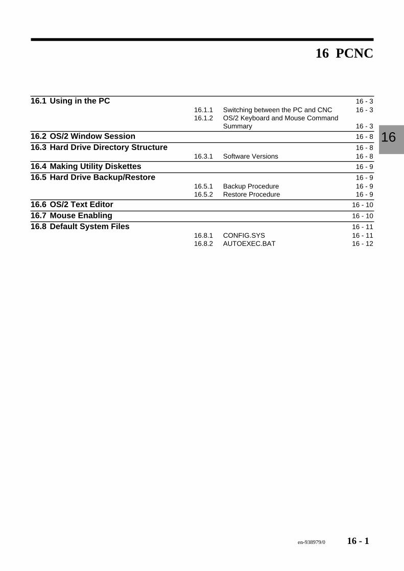
en-938979/0 16 - 1
PCNC
16
16 PCNC
16.1 Using in the PC 16 - 316.1.1 Switching between the PC and CNC 16 - 316.1.2 OS/2 Keyboard and Mouse Command
Summary 16 - 3
16.2 OS/2 Window Session 16 - 8
16.3 Hard Drive Directory Structure 16 - 816.3.1 Software Versions 16 - 8
16.4 Making Utility Diskettes 16 - 9
16.5 Hard Drive Backup/Restore 16 - 916.5.1 Backup Procedure 16 - 916.5.2 Restore Procedure 16 - 9
16.6 OS/2 Text Editor 16 - 10
16.7 Mouse Enabling 16 - 10
16.8 Default System Files 16 - 1116.8.1 CONFIG.SYS 16 - 1116.8.2 AUTOEXEC.BAT 16 - 12

16 - 2 en-938979/0
en-938979/0 16 - 3
PCNC
16
Some versions of the NUM 1060 come equipped with an integral PC (Personal Computer) built into the rack. Thereare some special maintenance issues which should be considered for a PCNC version.
The most important item to consider for maintenance is that of hard drive backup and restore functions. Since thesystem has a built in hard drive, it is very important that the contents of this disk be backed up. In the event that a harddrive does fail, you must be able to replace the drive and reload the software quickly to get the machine back up. Thischapter is devoted to the configuration of the PC.
16.1 Using in the PCThe first thing you must learn is to do is to navigate around the PC. There are numerous keystroke and mousecommands which you will need to know to be proficient at this. This section describes those functions.
16.1.1 Switching between the PC and CNC
From CNC to PC Display
Pressing ALT+F9 on the keyboard displays a screen similar to the one on the right.
From PC to CNC Display
1. Locate the minimised window icon and open it by double clicking it with the mouse.
2. Locate the NUM Symbol icon within this window and double click it with the mouse.
16.1.2 OS/2 Keyboard and Mouse Command Summary
Keyboard The following tables list some of the most common tasks you can do, using either thekeyboard or a mouse.
The plus (+) sign between key names means to press and hold down the keys in theorder shown and release them together.
Mouse When a column is left blank under the Mouse heading, it means that there is noequivalent mouse function. The keyboard must be used.
The following terms are used to describe actions taken with a mouse.
Click Press and release a mouse button. Instructions explain whether you should clickmouse button 1 or 2.
Double-Click Press and release mouse button 1 twice in quick succession.
Drag Move an object across the computer screen with a mouse.
Open Point to an ojbect and double click. Instructions explain which object to point to.
Point Move the mouse pointer.
Select Point to an object and click mouse button 1. Instructions explain which object to pointto.
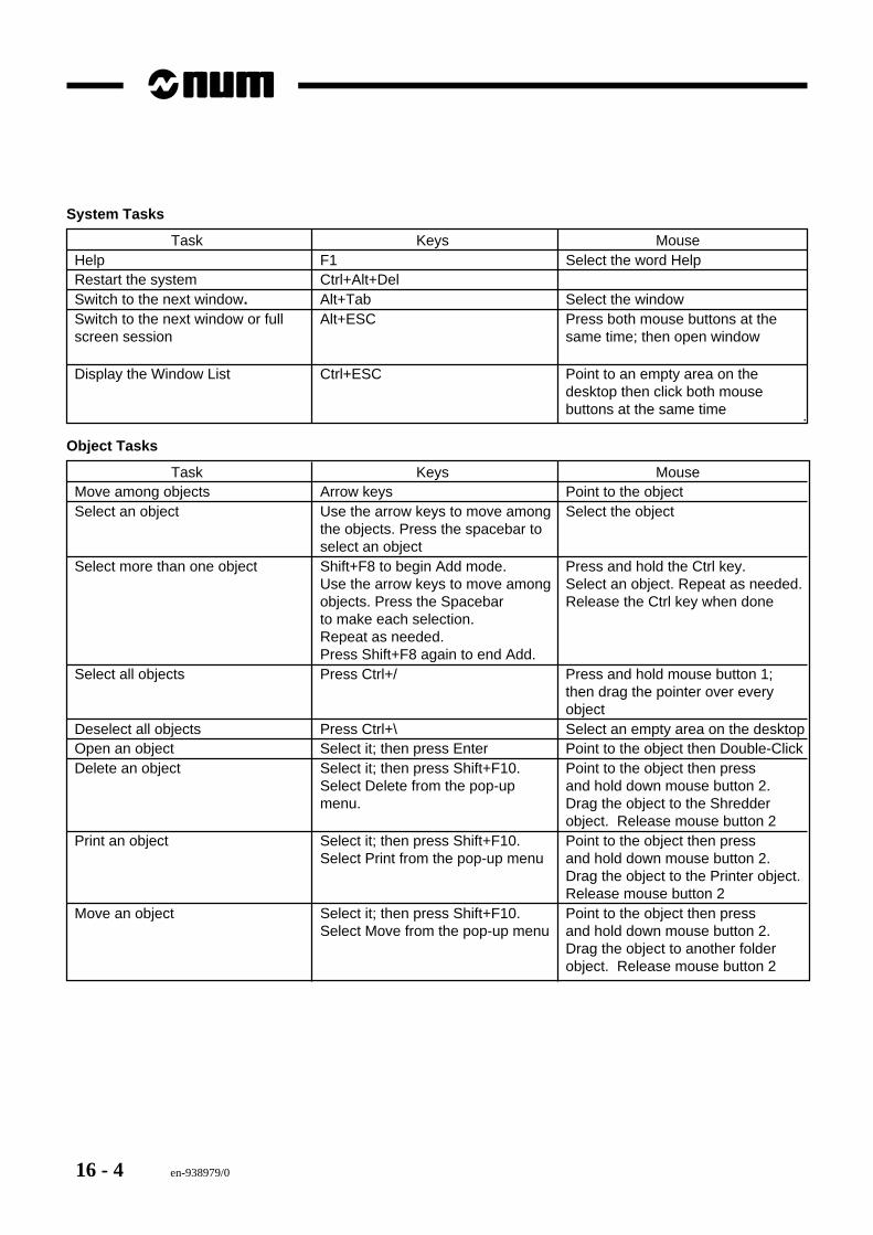
16 - 4 en-938979/0
System Tasks
Task Keys MouseHelp F1 Select the word HelpRestart the system Ctrl+Alt+DelSwitch to the next window. Alt+Tab Select the windowSwitch to the next window or full Alt+ESC Press both mouse buttons at thescreen session same time; then open window
Display the Window List Ctrl+ESC Point to an empty area on thedesktop then click both mousebuttons at the same time .
Object Tasks
Task Keys MouseMove among objects Arrow keys Point to the objectSelect an object Use the arrow keys to move among Select the object
the objects. Press the spacebar toselect an object
Select more than one object Shift+F8 to begin Add mode. Press and hold the Ctrl key.Use the arrow keys to move among Select an object. Repeat as needed.objects. Press the Spacebar Release the Ctrl key when doneto make each selection.Repeat as needed.Press Shift+F8 again to end Add.
Select all objects Press Ctrl+/ Press and hold mouse button 1;then drag the pointer over everyobject
Deselect all objects Press Ctrl+\ Select an empty area on the desktopOpen an object Select it; then press Enter Point to the object then Double-ClickDelete an object Select it; then press Shift+F10. Point to the object then press
Select Delete from the pop-up and hold down mouse button 2.menu. Drag the object to the Shredder
object. Release mouse button 2Print an object Select it; then press Shift+F10. Point to the object then press
Select Print from the pop-up menu and hold down mouse button 2.Drag the object to the Printer object.Release mouse button 2
Move an object Select it; then press Shift+F10. Point to the object then pressSelect Move from the pop-up menu and hold down mouse button 2.
Drag the object to another folderobject. Release mouse button 2
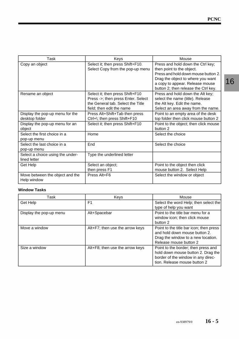
en-938979/0 16 - 5
PCNC
16
Task Keys MouseCopy an object Select it; then press Shift+F10. Press and hold down the Ctrl key;
Select Copy from the pop-up menu then point to the object.Press and hold down mouse button 2.Drag the object to where you wanta copy to appear. Release mousebutton 2; then release the Ctrl key.
Rename an object Select it; then press Shift+F10 Press and hold down the Alt key;Press ->; then press Enter. Select select the name (title). Releasethe General tab. Select the Title the Alt key. Edit the name.field; then edit the name Select an area away from the name.
Display the pop-up menu for the Press Alt+Shift+Tab then press Point to an empty area of the deskdesktop folder Ctrl+\; then press Shift+F10 top folder then click mouse button 2Display the pop-up menu for an Select it; then press Shift+F10 Point to the object; then click mouseobject button 2Select the first choice in a Home Select the choicepop-up menuSelect the last choice in a End Select the choicepop-up menuSelect a choice using the under- Type the underlined letterlined letterGet Help Select an object; Point to the object then click
then press F1 mouse button 2. Select HelpMove between the object and the Press Alt+F6 Select the window or objectHelp window
Window Tasks
Task Keys MouseGet Help F1 Select the word Help; then select the
type of help you wantDisplay the pop-up menu Alt+Spacebar Point to the title bar menu for a
window icon; then click mousebutton 2
Move a window Alt+F7; then use the arrow keys Point to the title bar icon; then pressand hold down mouse button 2.Drag the window to a new location.Release mouse button 2
Size a window Alt+F8; then use the arrow keys Point to the border; then press andhold down mouse button 2. Drag theborder of the window in any direc-tion. Release mouse button 2
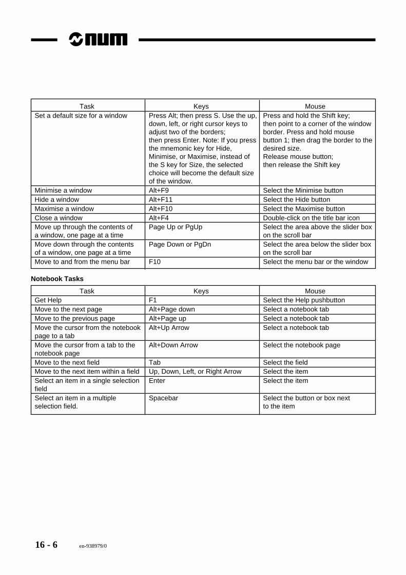
16 - 6 en-938979/0
Task Keys MouseSet a default size for a window Press Alt; then press S. Use the up, Press and hold the Shift key;
down, left, or right cursor keys to then point to a corner of the windowadjust two of the borders; border. Press and hold mousethen press Enter. Note: If you press button 1; then drag the border to thethe mnemonic key for Hide, desired size.Minimise, or Maximise, instead of Release mouse button;the S key for Size, the selected then release the Shift keychoice will become the default sizeof the window.
Minimise a window Alt+F9 Select the Minimise buttonHide a window Alt+F11 Select the Hide buttonMaximise a window Alt+F10 Select the Maximise buttonClose a window Alt+F4 Double-click on the title bar iconMove up through the contents of Page Up or PgUp Select the area above the slider boxa window, one page at a time on the scroll barMove down through the contents Page Down or PgDn Select the area below the slider boxof a window, one page at a time on the scroll barMove to and from the menu bar F10 Select the menu bar or the window
Notebook Tasks
Task Keys MouseGet Help F1 Select the Help pushbuttonMove to the next page Alt+Page down Select a notebook tabMove to the previous page Alt+Page up Select a notebook tabMove the cursor from the notebook Alt+Up Arrow Select a notebook tabpage to a tabMove the cursor from a tab to the Alt+Down Arrow Select the notebook pagenotebook pageMove to the next field Tab Select the fieldMove to the next item within a field Up, Down, Left, or Right Arrow Select the itemSelect an item in a single selection Enter Select the itemfieldSelect an item in a multiple Spacebar Select the button or box nextselection field. to the item
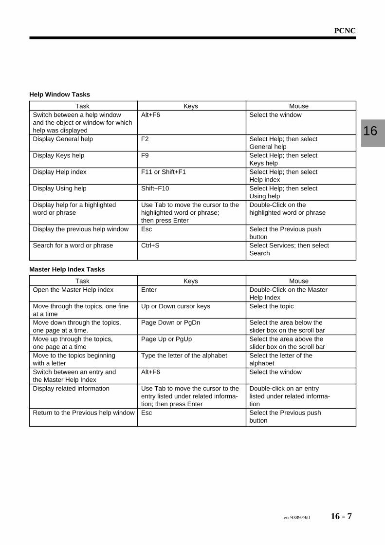
en-938979/0 16 - 7
PCNC
16
Help Window Tasks
Task Keys MouseSwitch between a help window Alt+F6 Select the windowand the object or window for whichhelp was displayedDisplay General help F2 Select Help; then select
General helpDisplay Keys help F9 Select Help; then select
Keys helpDisplay Help index F11 or Shift+F1 Select Help; then select
Help indexDisplay Using help Shift+F10 Select Help; then select
Using helpDisplay help for a highlighted Use Tab to move the cursor to the Double-Click on theword or phrase highlighted word or phrase; highlighted word or phrase
then press EnterDisplay the previous help window Esc Select the Previous push
buttonSearch for a word or phrase Ctrl+S Select Services; then select
Search
Master Help Index Tasks
Task Keys MouseOpen the Master Help index Enter Double-Click on the Master
Help IndexMove through the topics, one fine Up or Down cursor keys Select the topicat a timeMove down through the topics, Page Down or PgDn Select the area below theone page at a time. slider box on the scroll barMove up through the topics, Page Up or PgUp Select the area above theone page at a time slider box on the scroll barMove to the topics beginning Type the letter of the alphabet Select the letter of thewith a letter alphabetSwitch between an entry and Alt+F6 Select the windowthe Master Help IndexDisplay related information Use Tab to move the cursor to the Double-click on an entry
entry listed under related informa- listed under related informa-tion; then press Enter tion
Return to the Previous help window Esc Select the Previous pushbutton
16 - 8 en-938979/0
16.2 OS/2 Window SessionDuring system maintenance, it may be necessary to open an OS/2 session to check the directories on the hard diskor manipulate files. Access to this mode is from the Desktop.
Procedure
1. Find and double-click the OS/2 system icon on the desktop.2. Locate the OS/2 Window Session icon in the OS/2 System window, and double-click it.3. This opens an OS/2 windowed session. This session allows DOS-like commands, such as choose directory (CD),
make directory (MD), copy file (COPY), etc. To leave this session, type EXIT and press ENTER.
From this session you can browse the hard drive to determine if all is well with OS/2 and the special NUM files storedon the hard drive. See Section 16.3.
16.3 Hard Drive Directory StructureStrict compliance with the structure of certain directories containing files dedicated to the NUM application is required.The files listed below must be located in the specified directories.
C:\NUM\DRIVER\MEM_GLB.SYS
C:\NUM\GRAPHIC\CODES.NUM
\GPCCODES.NUM
\GR_PC.EXE
\NUM12x18.DLL
\NUM12x36.DLL
\NUM16x12.DLL
\NUM16x24.DLL
\NUM24x56.DLL
\NUM6x18.DLL
\NUM8x12.DLL
\NUM9x12.DLL
C:\OS2\DLL\NUMHOOKS.DLL
16.3.1 Software Versions
The files in these directories exist in several versions, depending on the software installed on the CNC. Since not allthe versions are mutually compatible, it is not recommended to replace files by other files which have a different index.In case of doubt, check with your local NUM agent, specifying the version of software on your CNC.
en-938979/0 16 - 9
PCNC
16
16.4 Making Utility DiskettesIn order to backup and restore the system hard drive, it is necessary to make a set of utility diskettes. These diskettesare created from the OS/2 Desktop:- Find and double-click the OS/2 System icon on the desktop- In the window that opens, select and double-click the SYSTEM SETUP icon- Find and double-click the UTILITY DISK icon and follow the instructions on the screen.
16.5 Hard Drive Backup/RestoreIn order to make hard drive backup diskettes you must be in a pure OS/2 session with no NUM files running. In orderto accomplish this, use the utility diskettes made in section 16.4.
16.5.1 Backup Procedure
1. Power down the CNC completely.2. Insert utility diskette 1 into the floppy drive and power on the CNC.3. You will be prompted for loading each diskette in order.4. After OS/2 has finished booting, the machine will be inoperable, but you can run the PC.5. Insert utility diskette 3 into the floppy drive.6. Type "Backup C: A: /S" then press ENTER.7. You will be prompted to insert as many as thirty-five (35) diskettes during this process. So be prepared and have
enough diskettes on hand.8. When you are prompted that the backup is completed, remove the last diskette from the floppy drive, and power
down the CNC.9. Power up the CNC after 1 to 2 minutes.10. Hard drive backup is completed.
16.5.2 Restore Procedure
1. Power down the CNC completely.2. Insert utility diskette 1 into the floppy drive and power on the CNC.3. You will be prompted for loading each diskette in order.4. After OS/2 has finished booting, the machine will be inoperable, but you can run the PC.5. Insert utility diskette 3 into the floppy drive.6. Type "Restore A: C: /S" then press ENTER.7. You will be prompted to insert as many as thirty-five (35) diskettes during this process.8. When you are prompted that the restore is completed, remove the last diskette from the floppy drive, and power
down the CNC.9. Power up the CNC after 1 to 2 minutes.10. Hard drive restoration is completed.
REMARK There are other backup methods that are easier to use, but they require availableof a special device, such as tape streamer or a removable hard disk. A methodbased on the Iomega Zip drive has been tested. For more information, ask yourlocal NUM dealer.
16 - 10 en-938979/0
16.6 OS/2 Text EditorOS/2 has a built-in text editor which is accessed via an OS/2 session.
Procedure
1. Find and double-click the OS/2 system icon on the desktop.2. Locate the OS/2 Window Session icon in the OS/2 System window, and double-click it.3. This opens an OS/2 windowed session. This session allows DOS-like commands, such as choose directory (CD),
make directory (MD), copy file (COPY), etc. To leave this session, type EXIT and press ENTER.4. Type "ED flename.ext" and press ENTER. The editor starts and the file opens.5. To exit the editor, double click on the upper left-hand corner of the window and you will be prompted to save your
file etc.6. To leave this session type EXIT at the prompt and press ENTER.
From this editor you can edit the PC’s CONFIG.SYS or AUTOEXEC.BAT files.
16.7 Mouse EnablingIn order to enable or disable the mouse, you will have to access the system setup window. The procedure is outlinedbelow.
Procedure
1. Find and double-click the OS/2 system icon on the desktop.2. Locate the SYSTEM SETUP icon in the OS/2 System window, and double-click it.3. The System Setup window opens.4. Locate the CONFIGURE PREINSTALLED SYSTEM ICON and double-click it.5. Click the MOUSE selection and press the OK button.6. Select the type of mouse which you have. Typically two-button mice use "SERIAL POINTING DEVICE" while
three-button mice use "LOGITECH M SERIES". But you might have to experiment to find the right selection.7. Click the OK button when your selections are made, and the CNC will tell you that you will have to reboot to activate
the new configuration.8. Close all windows on the PC, and return to the CNC.9. Power down the CNC.10. After 1 to 2 minutes, power up the CNC and the new mouse configuration will be active.
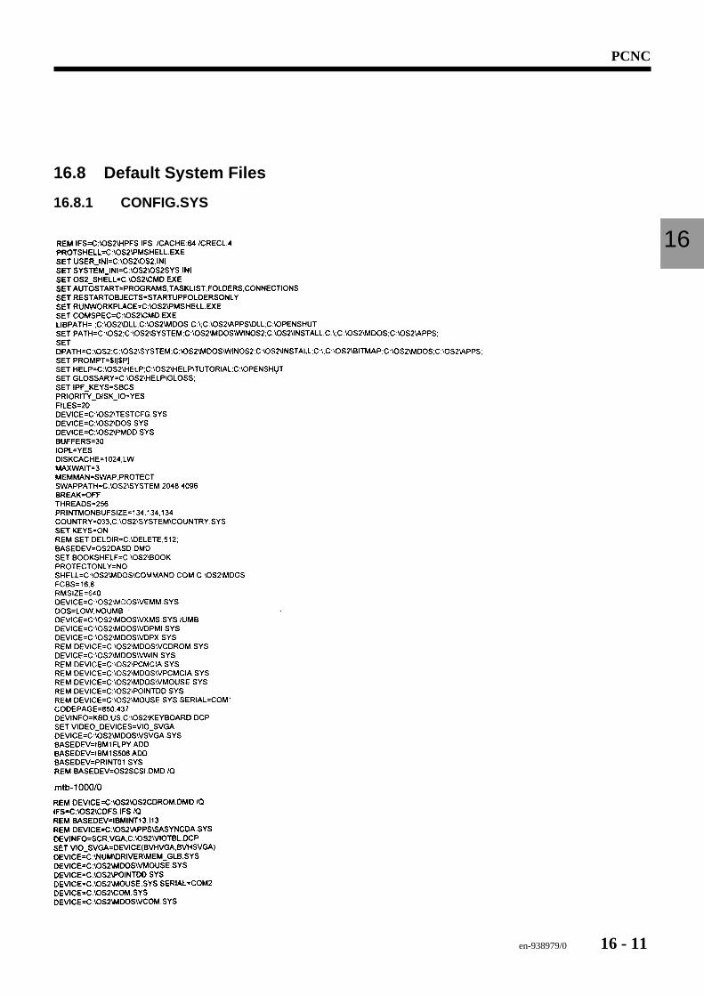
en-938979/0 16 - 11
PCNC
16
16.8 Default System Files
16.8.1 CONFIG.SYS
16 - 12 en-938979/0
16.8.2 AUTOEXEC.BAT
en-938979/0 17 - 1
Option Grid Settings
17
17 Option Grid Settings
17.1 Viewing the Options 17 - 317.1.1 Number of Axes 17 - 317.1.2 Memory Sizes 17 - 417.1.3 Option Setting History 17 - 417.1.4 System Bus Hardware Configuration 17 - 517.1.5 PLC Bus Hardware Configuration 17 - 5
17.2 Setting the Options 17 - 617.2.1 Option Data 17 - 617.2.2 Settings 17 - 717.2.3 PERSOTool 17 - 7

17 - 2 en-938979/0
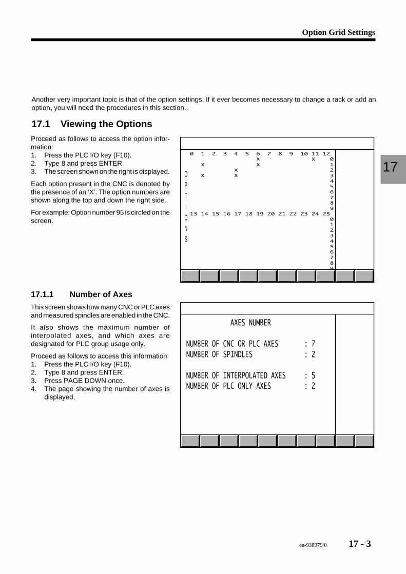
en-938979/0 17 - 3
Option Grid Settings
17
Another very important topic is that of the option settings. If it ever becomes necessary to change a rack or add anoption, you will need the procedures in this section.
17.1 Viewing the OptionsProceed as follows to access the option infor-mation:1. Press the PLC l/O key (F10).2. Type 8 and press ENTER.3. The screen shown on the right is displayed.
Each option present in the CNC is denoted bythe presence of an ‘X’. The option numbers areshown along the top and down the right side.
For example: Option number 95 is circled on thescreen.
OPTIONS
0 1 2 3 4 5 6 7 8 9 10 11 12 X X 0 X X 1 X 2 X X 3 4 5 6 7 8 9 13 14 15 16 17 18 19 20 21 22 23 24 25 0 1 2 3 4 5 6 7 8 9
17.1.1 Number of Axes
This screen shows how many CNC or PLC axesand measured spindles are enabled in the CNC.
It also shows the maximum number ofinterpolated axes, and which axes aredesignated for PLC group usage only.
Proceed as follows to access this information:1. Press the PLC l/O key (F10).2. Type 8 and press ENTER.3. Press PAGE DOWN once.4. The page showing the number of axes is
displayed.
AXES NUMBER
NUMBER OF CNC OR PLC AXES : 7NUMBER OF SPINDLES : 2
NUMBER OF INTERPOLATED AXES : 5NUMBER OF PLC ONLY AXES : 2
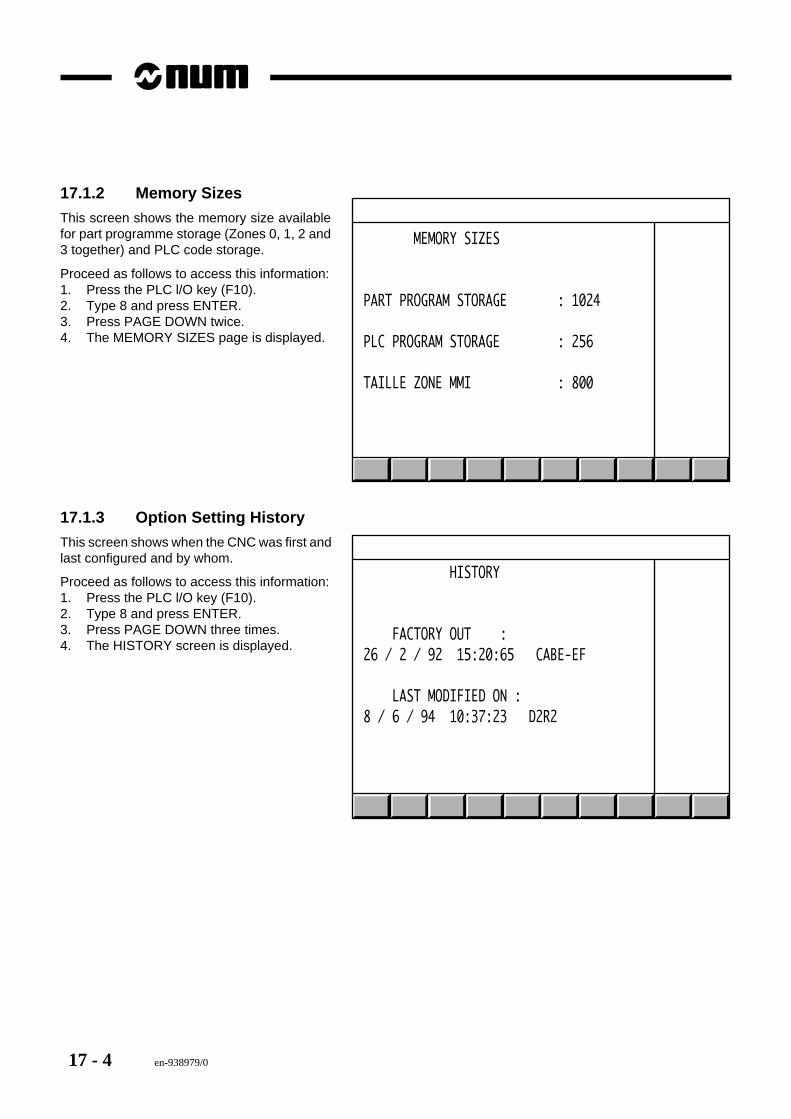
17 - 4 en-938979/0
17.1.2 Memory Sizes
This screen shows the memory size availablefor part programme storage (Zones 0, 1, 2 and3 together) and PLC code storage.
Proceed as follows to access this information:1. Press the PLC l/O key (F10).2. Type 8 and press ENTER.3. Press PAGE DOWN twice.4. The MEMORY SIZES page is displayed.
MEMORY SIZES
PART PROGRAM STORAGE : 1024
PLC PROGRAM STORAGE : 256
TAILLE ZONE MMI : 800
17.1.3 Option Setting History
This screen shows when the CNC was first andlast configured and by whom.
Proceed as follows to access this information:1. Press the PLC l/O key (F10).2. Type 8 and press ENTER.3. Press PAGE DOWN three times.4. The HISTORY screen is displayed.
HISTORY
FACTORY OUT :26 / 2 / 92 15:20:65 CABE-EF
LAST MODIFIED ON :8 / 6 / 94 10:37:23 D2R2
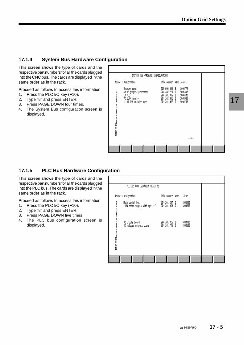
en-938979/0 17 - 5
Option Grid Settings
17
17.1.4 System Bus Hardware Configuration
SYSTEM BUS HARDWARE CONFIGURATION
Address Designation File number Vers Ident.
Unknown card 000 000 000 8 $0007F8 0 4M V2 graphic processor 204 202 778 0 $005340 1 1M PLC 204 201 935 0 $004B00 2 V2 1,7M memory 204 202 301 0 $008D80 3 4 V1 14b encoder axes 204 201 982 0 $000E00 4 5 6 7 8 9 10 11 12 13 .../...
17.1.5 PLC Bus Hardware Configuration
PLC BUS CONFIGURATION (RACK 0)
Address Designation File number Vers. Ident.
0 Main serial bus 204 201 857 0 $000000 0 130W power supply with optic F. 204 201 950 0 $000000 1 2 3 4 5 32 inputs board 204 201 926 0 $000A00 6 32 relayed outputs board 204 201 746 0 $000100 7 8 9 10 11 12 13
This screen shows the type of cards and therespective part numbers for all the cards pluggedinto the CNC bus. The cards are displayed in thesame order as in the rack.
Proceed as follows to access this information:1. Press the PLC l/O key (F10).2. Type "8" and press ENTER.3. Press PAGE DOWN four times.4. The System Bus configuration screen is
displayed.
This screen shows the type of cards and therespective part numbers for all the cards pluggedinto the PLC bus. The cards are displayed in thesame order as in the rack.
Proceed as follows to access this information:1. Press the PLC l/O key (F10).2. Type "8" and press ENTER.3. Press PAGE DOWN five times.4. The PLC bus configuration screen is
displayed.
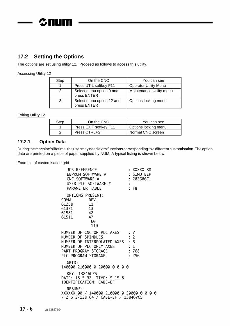
17 - 6 en-938979/0
17.2 Setting the OptionsThe options are set using utility 12. Proceed as follows to access this utility.
Accessing Utility 12
Step On the CNC You can see1 Press UTIL softkey F11 Operator Utility Menu2 Select menu option 0 and Maintenance Utility menu
press ENTER3 Select menu option 12 and Options locking menu
press ENTER
Exiting Utility 12
Step On the CNC You can see1 Press EXIT softkey F11 Options locking menu2 Press CTRL+S Normal CNC screen
17.2.1 Option Data
During the machine’s lifetime, the user may need extra functions corresponding to a different customisation. The optiondata are printed on a piece of paper supplied by NUM. A typical listing is shown below.
Example of customisation grid
JOB REFERENCE : XXXXX 88EEPROM SOFTWARE # : SIMU EEPCNC SOFTWARE # : 282686C1USER PLC SOFTWARE # :PARAMETER TABLE : F8
OPTIONS PRESENT:COMM. DEV.61258 1161371 1361581 4261511 47
60110
NUMBER OF CNC OR PLC AXES : 7NUMBER OF SPINDLES : 2NUMBER OF INTERPOLATED AXES : 5NUMBER OF PLC ONLY AXES : 1PART PROGRAM STORAGE : 768PLC PROGRAM STORAGE : 256
GRID:140000 210000 0 20000 0 0 0 0
KEY: 13846C75DATE: 18 5 92 TIME: 9 15 8IDENTIFICATION: CABE-EF
RESUME:XXXXXX 00 / 140000 210000 0 20000 0 0 0 07 2 5 2/128 64 / CABE-EF / 138467C5
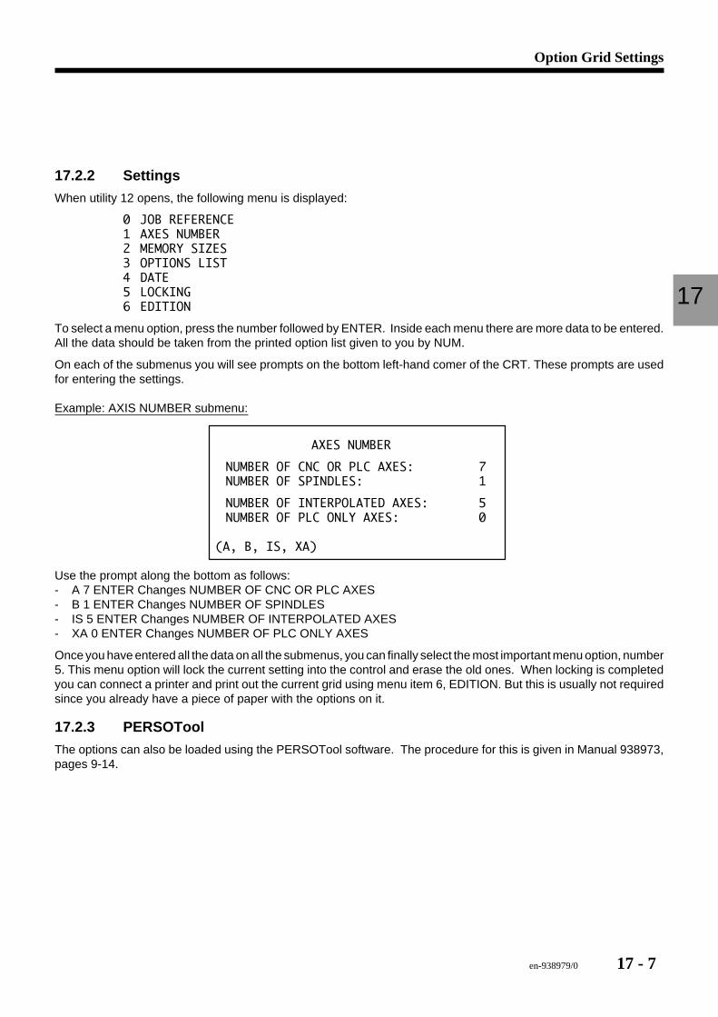
en-938979/0 17 - 7
Option Grid Settings
17
17.2.2 Settings
When utility 12 opens, the following menu is displayed:
0 JOB REFERENCE1 AXES NUMBER2 MEMORY SIZES3 OPTIONS LIST4 DATE5 LOCKING6 EDITION
To select a menu option, press the number followed by ENTER. Inside each menu there are more data to be entered.All the data should be taken from the printed option list given to you by NUM.
On each of the submenus you will see prompts on the bottom left-hand comer of the CRT. These prompts are usedfor entering the settings.
Example: AXIS NUMBER submenu:
AXES NUMBER
NUMBER OF CNC OR PLC AXES: 7NUMBER OF SPINDLES: 1
NUMBER OF INTERPOLATED AXES: 5NUMBER OF PLC ONLY AXES: 0
(A, B, IS, XA)
Use the prompt along the bottom as follows:- A 7 ENTER Changes NUMBER OF CNC OR PLC AXES- B 1 ENTER Changes NUMBER OF SPINDLES- IS 5 ENTER Changes NUMBER OF INTERPOLATED AXES- XA 0 ENTER Changes NUMBER OF PLC ONLY AXES
Once you have entered all the data on all the submenus, you can finally select the most important menu option, number5. This menu option will lock the current setting into the control and erase the old ones. When locking is completedyou can connect a printer and print out the current grid using menu item 6, EDITION. But this is usually not requiredsince you already have a piece of paper with the options on it.
17.2.3 PERSOTool
The options can also be loaded using the PERSOTool software. The procedure for this is given in Manual 938973,pages 9-14.

17 - 8 en-938979/0
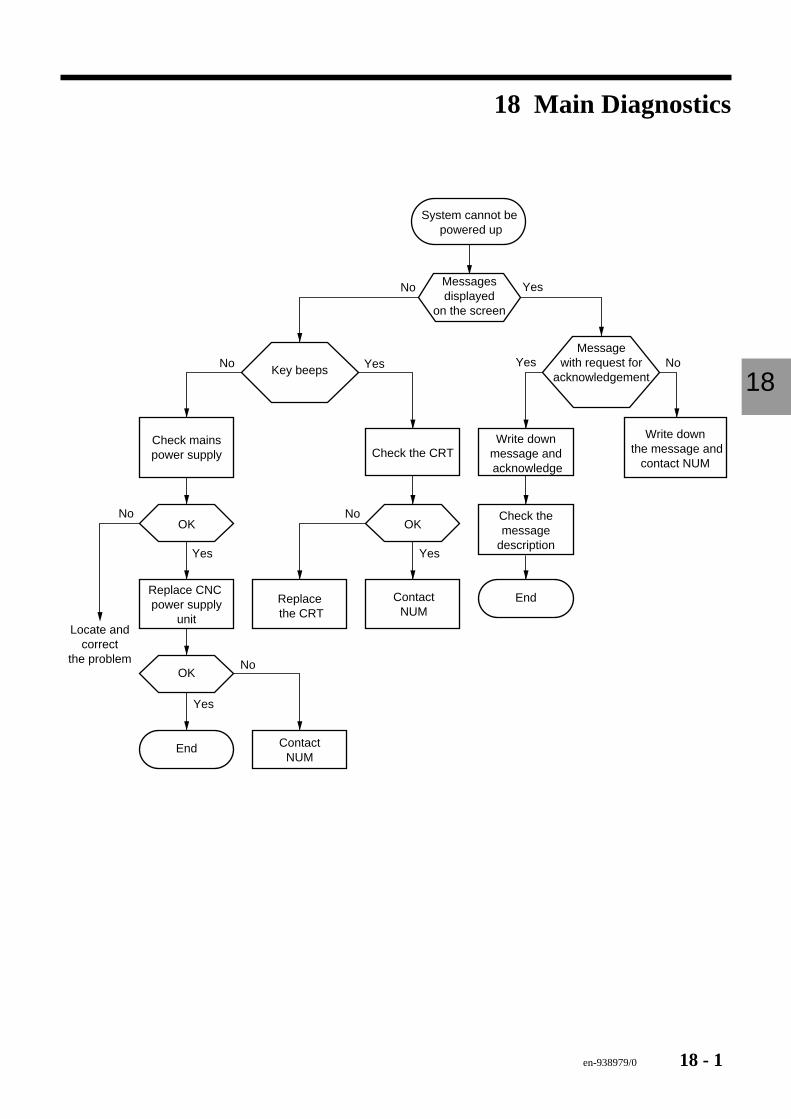
en-938979/0 18 - 1
Main Diagnostics
18
18 Main Diagnostics
System cannot be powered up
End
End
Write down the message and
contact NUM
Write downmessage and acknowledge
Check themessage
description
Check the CRT
ContactNUM
Replace the CRT
ContactNUM
Replace CNC power supply
unitLocate and
correctthe problem
Check mainspower supply
Messagesdisplayed
on the screen
Messagewith request for
acknowledgementKey beeps
OKOK
OK
No Yes
No Yes
No
Yes No
YesYes
Yes
No No
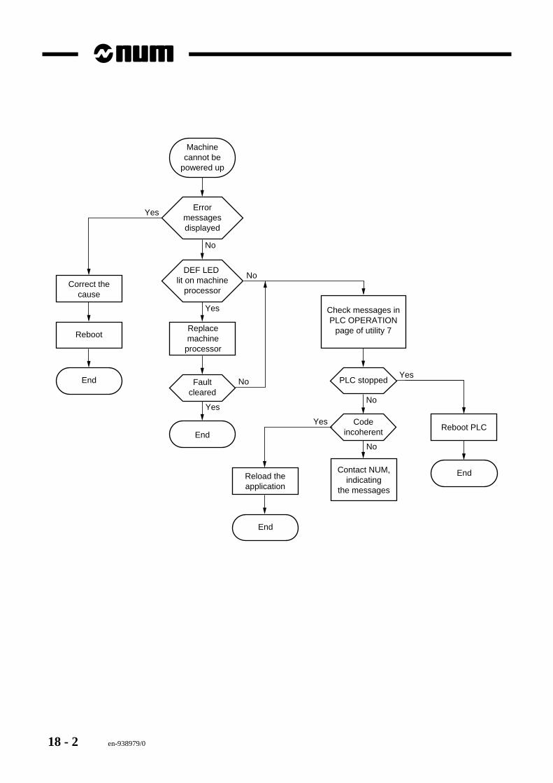
18 - 2 en-938979/0
Check messages inPLC OPERATION
page of utility 7
Contact NUM,indicating
the messages
No
Yes
Machinecannot be
powered up
End
End
End Faultcleared
PLC stopped
Codeincoherent
DEF LED lit on machine
processor
Errormessagesdisplayed
Replacemachine
processor
Correct thecause
Reboot
Reload theapplication
End
Reboot PLC
No
No
Yes
Yes
No
No
Yes
Yes
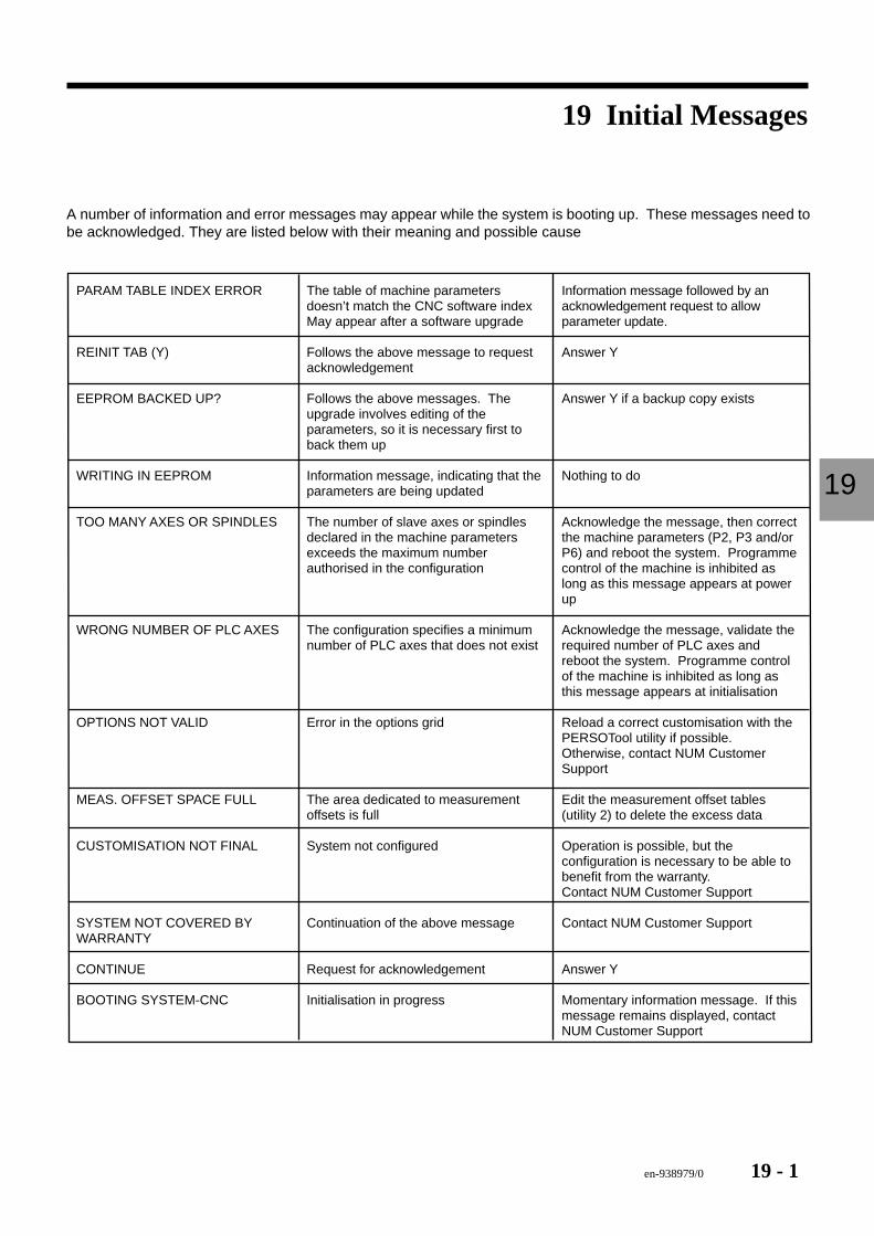
en-938979/0 19 - 1
Initial Massages
19
19 Initial Messages
A number of information and error messages may appear while the system is booting up. These messages need tobe acknowledged. They are listed below with their meaning and possible cause
The table of machine parameters doesn’t match the CNC software index May appear after a software upgrade
Follows the above message to request acknowledgement
Follows the above messages. The upgrade involves editing of the parameters, so it is necessary first to back them up
Information message, indicating that the parameters are being updated
The number of slave axes or spindles declared in the machine parameters exceeds the maximum number authorised in the configuration
The configuration specifies a minimum number of PLC axes that does not exist
Error in the options grid
The area dedicated to measurement offsets is full
System not configured
Continuation of the above message
Request for acknowledgement
Initialisation in progress
PARAM TABLE INDEX ERROR
REINIT TAB (Y)
EEPROM BACKED UP?
WRITING IN EEPROM
TOO MANY AXES OR SPINDLES
WRONG NUMBER OF PLC AXES
OPTIONS NOT VALID
MEAS. OFFSET SPACE FULL
CUSTOMISATION NOT FINAL
SYSTEM NOT COVERED BY WARRANTY
CONTINUE
BOOTING SYSTEM-CNC
Information message followed by an acknowledgement request to allow parameter update.
Answer Y
Answer Y if a backup copy exists
Nothing to do
Acknowledge the message, then correct the machine parameters (P2, P3 and/or P6) and reboot the system. Programme control of the machine is inhibited as long as this message appears at power up
Acknowledge the message, validate the required number of PLC axes and reboot the system. Programme control of the machine is inhibited as long as this message appears at initialisation
Reload a correct customisation with the PERSOTool utility if possible. Otherwise, contact NUM Customer Support
Edit the measurement offset tables (utility 2) to delete the excess data
Operation is possible, but the configuration is necessary to be able to benefit from the warranty. Contact NUM Customer Support
Contact NUM Customer Support
Answer Y
Momentary information message. If this message remains displayed, contact NUM Customer Support
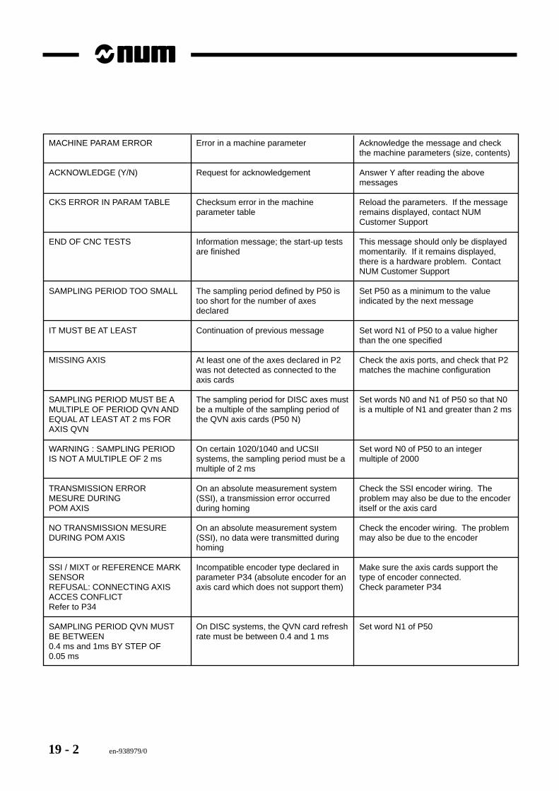
19 - 2 en-938979/0
MACHINE PARAM ERROR
ACKNOWLEDGE (Y/N)
CKS ERROR IN PARAM TABLE
END OF CNC TESTS
SAMPLING PERIOD TOO SMALL
IT MUST BE AT LEAST
MISSING AXIS
SAMPLING PERIOD MUST BE A MULTIPLE OF PERIOD QVN AND EQUAL AT LEAST AT 2 ms FOR AXIS QVN
WARNING : SAMPLING PERIOD IS NOT A MULTIPLE OF 2 ms
TRANSMISSION ERROR MESURE DURINGPOM AXIS
NO TRANSMISSION MESURE DURING POM AXIS
SSI / MIXT or REFERENCE MARK SENSOR REFUSAL: CONNECTING AXIS ACCES CONFLICT Refer to P34
SAMPLING PERIOD QVN MUST BE BETWEEN 0.4 ms and 1ms BY STEP OF 0.05 ms
Error in a machine parameter
Request for acknowledgement
Checksum error in the machine parameter table
Information message; the start-up tests are finished
The sampling period defined by P50 is too short for the number of axes declared
Continuation of previous message
At least one of the axes declared in P2 was not detected as connected to the axis cards
The sampling period for DISC axes must be a multiple of the sampling period of the QVN axis cards (P50 N)
On certain 1020/1040 and UCSII systems, the sampling period must be a multiple of 2 ms
On an absolute measurement system (SSI), a transmission error occurred during homing
On an absolute measurement system (SSI), no data were transmitted during homing
Incompatible encoder type declared in parameter P34 (absolute encoder for an axis card which does not support them)
On DISC systems, the QVN card refresh rate must be between 0.4 and 1 ms
Acknowledge the message and check the machine parameters (size, contents)
Answer Y after reading the above messages
Reload the parameters. If the message remains displayed, contact NUM Customer Support
This message should only be displayed momentarily. If it remains displayed, there is a hardware problem. Contact NUM Customer Support
Set P50 as a minimum to the value indicated by the next message
Set word N1 of P50 to a value higher than the one specified
Check the axis ports, and check that P2 matches the machine configuration
Set words N0 and N1 of P50 so that N0 is a multiple of N1 and greater than 2 ms
Set word N0 of P50 to an integer multiple of 2000
Check the SSI encoder wiring. The problem may also be due to the encoder itself or the axis card
Check the encoder wiring. The problem may also be due to the encoder
Make sure the axis cards support the type of encoder connected. Check parameter P34
Set word N1 of P50
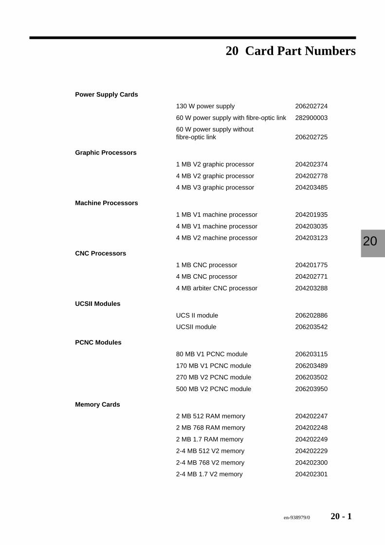
en-938979/0 20 - 1
Card Part Numbers
20
20 Card Part Numbers
Power Supply Cards
130 W power supply 206202724
60 W power supply with fibre-optic link 282900003
60 W power supply withoutfibre-optic link 206202725
Graphic Processors
1 MB V2 graphic processor 204202374
4 MB V2 graphic processor 204202778
4 MB V3 graphic processor 204203485
Machine Processors
1 MB V1 machine processor 204201935
4 MB V1 machine processor 204203035
4 MB V2 machine processor 204203123
CNC Processors
1 MB CNC processor 204201775
4 MB CNC processor 204202771
4 MB arbiter CNC processor 204203288
UCSII Modules
UCS II module 206202886
UCSII module 206203542
PCNC Modules
80 MB V1 PCNC module 206203115
170 MB V1 PCNC module 206203489
270 MB V2 PCNC module 206203502
500 MB V2 PCNC module 206203950
Memory Cards
2 MB 512 RAM memory 204202247
2 MB 768 RAM memory 204202248
2 MB 1.7 RAM memory 204202249
2-4 MB 512 V2 memory 204202229
2-4 MB 768 V2 memory 204202300
2-4 MB 1.7 V2 memory 204202301
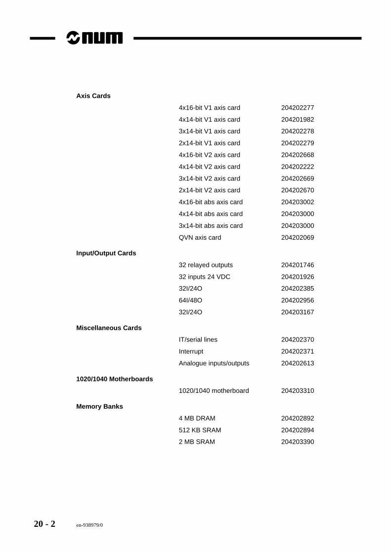
20 - 2 en-938979/0
Axis Cards
4x16-bit V1 axis card 204202277
4x14-bit V1 axis card 204201982
3x14-bit V1 axis card 204202278
2x14-bit V1 axis card 204202279
4x16-bit V2 axis card 204202668
4x14-bit V2 axis card 204202222
3x14-bit V2 axis card 204202669
2x14-bit V2 axis card 204202670
4x16-bit abs axis card 204203002
4x14-bit abs axis card 204203000
3x14-bit abs axis card 204203000
QVN axis card 204202069
Input/Output Cards
32 relayed outputs 204201746
32 inputs 24 VDC 204201926
32I/24O 204202385
64I/48O 204202956
32I/24O 204203167
Miscellaneous Cards
IT/serial lines 204202370
Interrupt 204202371
Analogue inputs/outputs 204202613
1020/1040 Motherboards
1020/1040 motherboard 204203310
Memory Banks
4 MB DRAM 204202892
512 KB SRAM 204202894
2 MB SRAM 204203390
en-938979/0 A - 1
List of Errors
A
Appendix A - List of Errors
A.1 Miscellaneous and Machine Errors A - 3
A.2 Parametric Programming Errors A - 5
A.3 Profile Geometry Programming (PGP) Errors A - 5
A.4 Miscellaneous errors A - 6
A.5 Axis Overtravel Errors A - 6
A.6 Structured Programming Errors A - 7
A.7 Axis Faults A - 7
A.8 Errors in Pocket Cycles A - 8

A - 2 en-938979/0
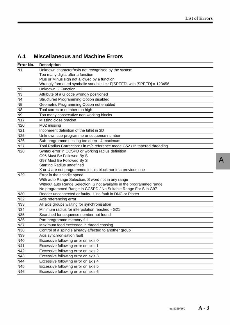
en-938979/0 A - 3
List of Errors
A
A.1 Miscellaneous and Machine ErrorsError No. DescriptionN1 Unknown character/Axis not recognised by the system
Too many digits after a functionPlus or Minus sign not allowed by a functionWrongly formatted symbolic variable i.e.: F[SPEED] with [SPEED] = 123456
N2 Unknown G FunctionN3 Attribute of a G code wrongly positionedN4 Structured Programming Option disabledN5 Geometric Programming Option not enabledN8 Tool corrector number too highN9 Too many consecutive non working blocksN17 Missing close bracketN20 M02 missingN21 Incoherent definition of the billet in 3DN25 Unknown sub-programme or sequence numberN26 Sub-programme nesting too deep - 4 maximumN27 Tool Radius Correction: / in m/c reference mode G52 / In tapered threadingN28 Syntax error in CCSPD or working radius definition
G96 Must Be Followed By SG97 Must Be Followed By SStarting Radius undefinedX or U are not programmed in this block nor in a previous one
N29 Error in the spindle speedWith auto Range Selection, S word not in any rangeWithout auto Range Selection, S not available in the programmed rangeNo programmed Range in CCSPD / No Suitable Range For S in G97
N30 Reader unconnected or faulty. Line fault in DNC or PlotterN32 Axis referencing errorN33 All axis groups waiting for synchronisationN34 Minimum radius for interpolation reached - G21N35 Searched for sequence number not foundN36 Part programme memory fullN37 Maximum feed exceeded in thread chasingN38 Control of a spindle already affected to another groupN39 Axis synchronisation faultN40 Excessive following error on axis 0N41 Excessive following error on axis 1N42 Excessive following error on axis 2N43 Excessive following error on axis 3N44 Excessive following error on axis 4N45 Excessive following error on axis 5N46 Excessive following error on axis 6
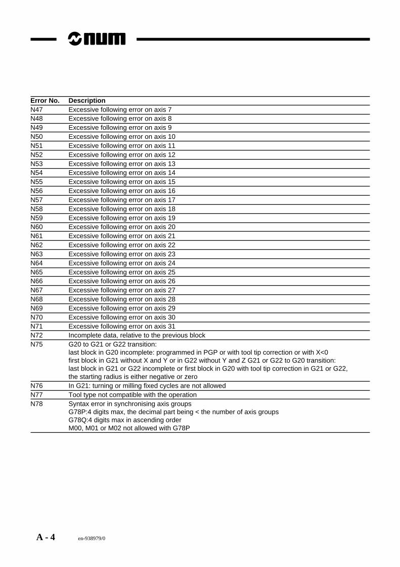
A - 4 en-938979/0
Error No. DescriptionN47 Excessive following error on axis 7N48 Excessive following error on axis 8N49 Excessive following error on axis 9N50 Excessive following error on axis 10N51 Excessive following error on axis 11N52 Excessive following error on axis 12N53 Excessive following error on axis 13N54 Excessive following error on axis 14N55 Excessive following error on axis 15N56 Excessive following error on axis 16N57 Excessive following error on axis 17N58 Excessive following error on axis 18N59 Excessive following error on axis 19N60 Excessive following error on axis 20N61 Excessive following error on axis 21N62 Excessive following error on axis 22N63 Excessive following error on axis 23N64 Excessive following error on axis 24N65 Excessive following error on axis 25N66 Excessive following error on axis 26N67 Excessive following error on axis 27N68 Excessive following error on axis 28N69 Excessive following error on axis 29N70 Excessive following error on axis 30N71 Excessive following error on axis 31N72 Incomplete data, relative to the previous blockN75 G20 to G21 or G22 transition:
last block in G20 incomplete: programmed in PGP or with tool tip correction or with X<0first block in G21 without X and Y or in G22 without Y and Z G21 or G22 to G20 transition:last block in G21 or G22 incomplete or first block in G20 with tool tip correction in G21 or G22,the starting radius is either negative or zero
N76 In G21: turning or milling fixed cycles are not allowedN77 Tool type not compatible with the operationN78 Syntax error in synchronising axis groups
G78P:4 digits max, the decimal part being < the number of axis groupsG78Q:4 digits max in ascending orderM00, M01 or M02 not allowed with G78P
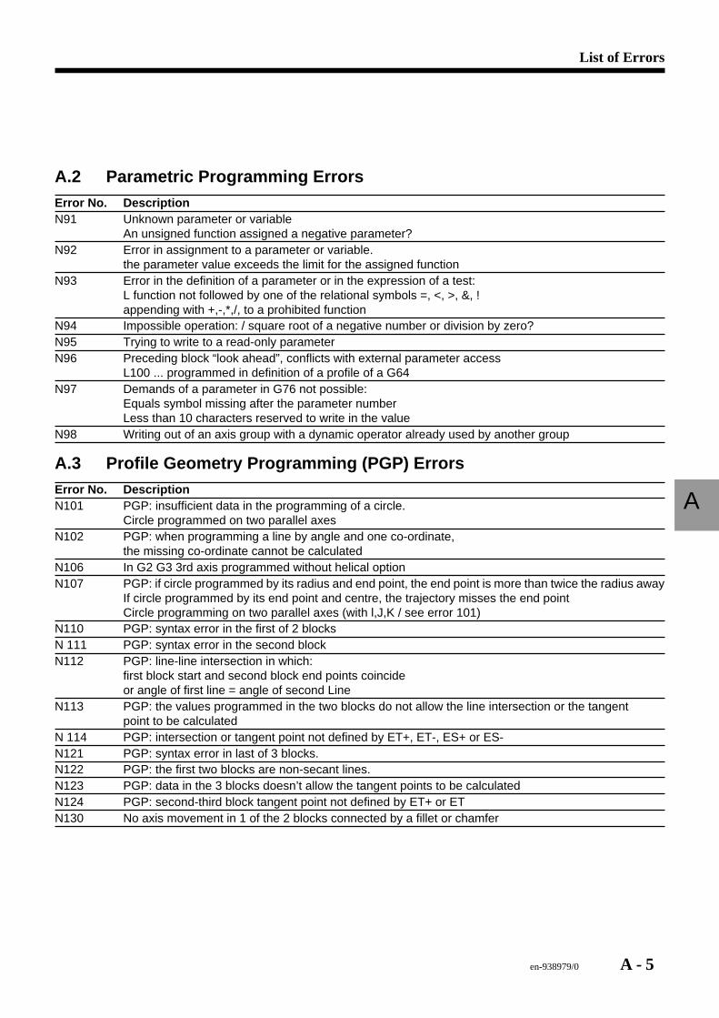
en-938979/0 A - 5
List of Errors
A
A.2 Parametric Programming ErrorsError No. DescriptionN91 Unknown parameter or variable
An unsigned function assigned a negative parameter?N92 Error in assignment to a parameter or variable.
the parameter value exceeds the limit for the assigned functionN93 Error in the definition of a parameter or in the expression of a test:
L function not followed by one of the relational symbols =, <, >, &, !appending with +,-,*,/, to a prohibited function
N94 Impossible operation: / square root of a negative number or division by zero?N95 Trying to write to a read-only parameterN96 Preceding block “look ahead”, conflicts with external parameter access
L100 ... programmed in definition of a profile of a G64N97 Demands of a parameter in G76 not possible:
Equals symbol missing after the parameter numberLess than 10 characters reserved to write in the value
N98 Writing out of an axis group with a dynamic operator already used by another group
A.3 Profile Geometry Programming (PGP) ErrorsError No. DescriptionN101 PGP: insufficient data in the programming of a circle.
Circle programmed on two parallel axesN102 PGP: when programming a line by angle and one co-ordinate,
the missing co-ordinate cannot be calculatedN106 In G2 G3 3rd axis programmed without helical optionN107 PGP: if circle programmed by its radius and end point, the end point is more than twice the radius away
If circle programmed by its end point and centre, the trajectory misses the end pointCircle programming on two parallel axes (with l,J,K / see error 101)
N110 PGP: syntax error in the first of 2 blocksN 111 PGP: syntax error in the second blockN112 PGP: line-line intersection in which:
first block start and second block end points coincideor angle of first line = angle of second Line
N113 PGP: the values programmed in the two blocks do not allow the line intersection or the tangentpoint to be calculated
N 114 PGP: intersection or tangent point not defined by ET+, ET-, ES+ or ES-N121 PGP: syntax error in last of 3 blocks.N122 PGP: the first two blocks are non-secant lines.N123 PGP: data in the 3 blocks doesn’t allow the tangent points to be calculatedN124 PGP: second-third block tangent point not defined by ET+ or ETN130 No axis movement in 1 of the 2 blocks connected by a fillet or chamfer
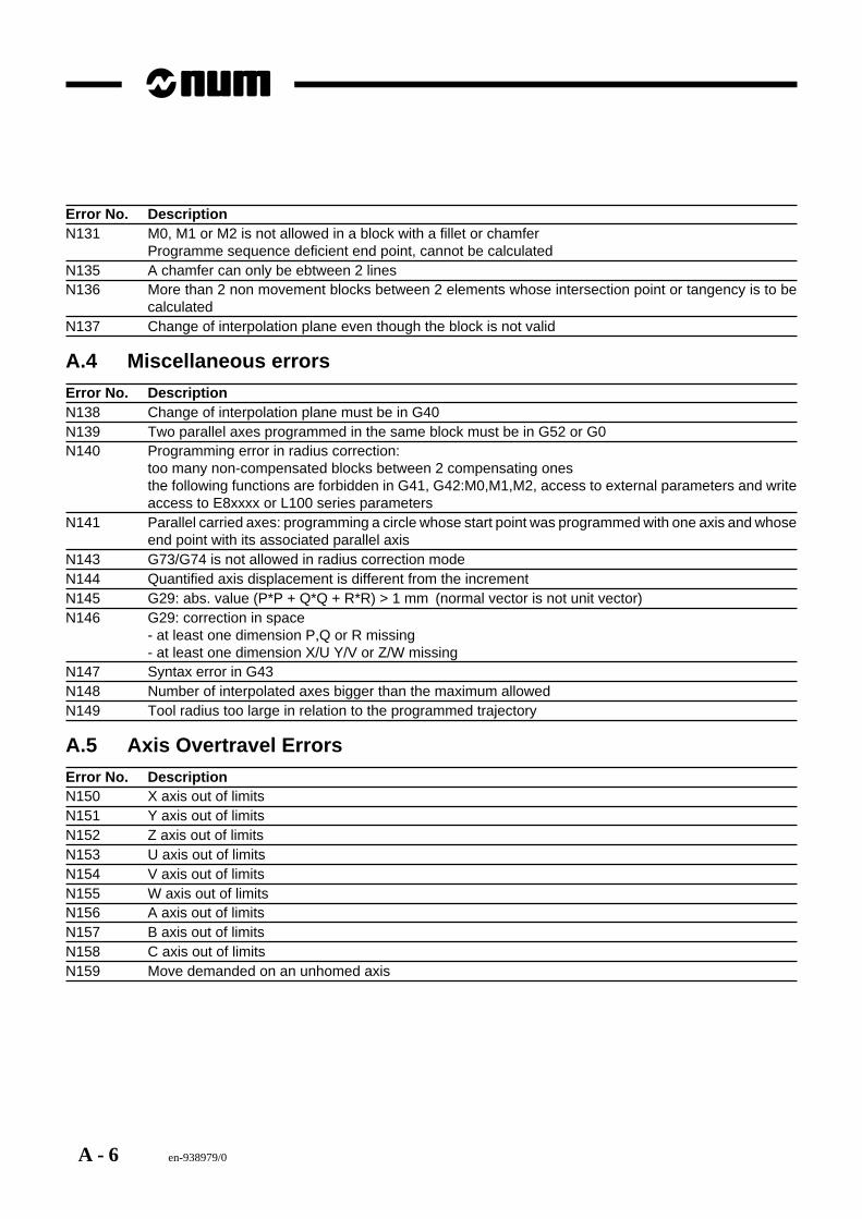
A - 6 en-938979/0
Error No. DescriptionN131 M0, M1 or M2 is not allowed in a block with a fillet or chamfer
Programme sequence deficient end point, cannot be calculatedN135 A chamfer can only be ebtween 2 linesN136 More than 2 non movement blocks between 2 elements whose intersection point or tangency is to be
calculatedN137 Change of interpolation plane even though the block is not valid
A.4 Miscellaneous errorsError No. DescriptionN138 Change of interpolation plane must be in G40N139 Two parallel axes programmed in the same block must be in G52 or G0N140 Programming error in radius correction:
too many non-compensated blocks between 2 compensating onesthe following functions are forbidden in G41, G42:M0,M1,M2, access to external parameters and writeaccess to E8xxxx or L100 series parameters
N141 Parallel carried axes: programming a circle whose start point was programmed with one axis and whoseend point with its associated parallel axis
N143 G73/G74 is not allowed in radius correction modeN144 Quantified axis displacement is different from the incrementN145 G29: abs. value (P*P + Q*Q + R*R) > 1 mm (normal vector is not unit vector)N146 G29: correction in space
- at least one dimension P,Q or R missing- at least one dimension X/U Y/V or Z/W missing
N147 Syntax error in G43N148 Number of interpolated axes bigger than the maximum allowedN149 Tool radius too large in relation to the programmed trajectory
A.5 Axis Overtravel ErrorsError No. DescriptionN150 X axis out of limitsN151 Y axis out of limitsN152 Z axis out of limitsN153 U axis out of limitsN154 V axis out of limitsN155 W axis out of limitsN156 A axis out of limitsN157 B axis out of limitsN158 C axis out of limitsN159 Move demanded on an unhomed axis
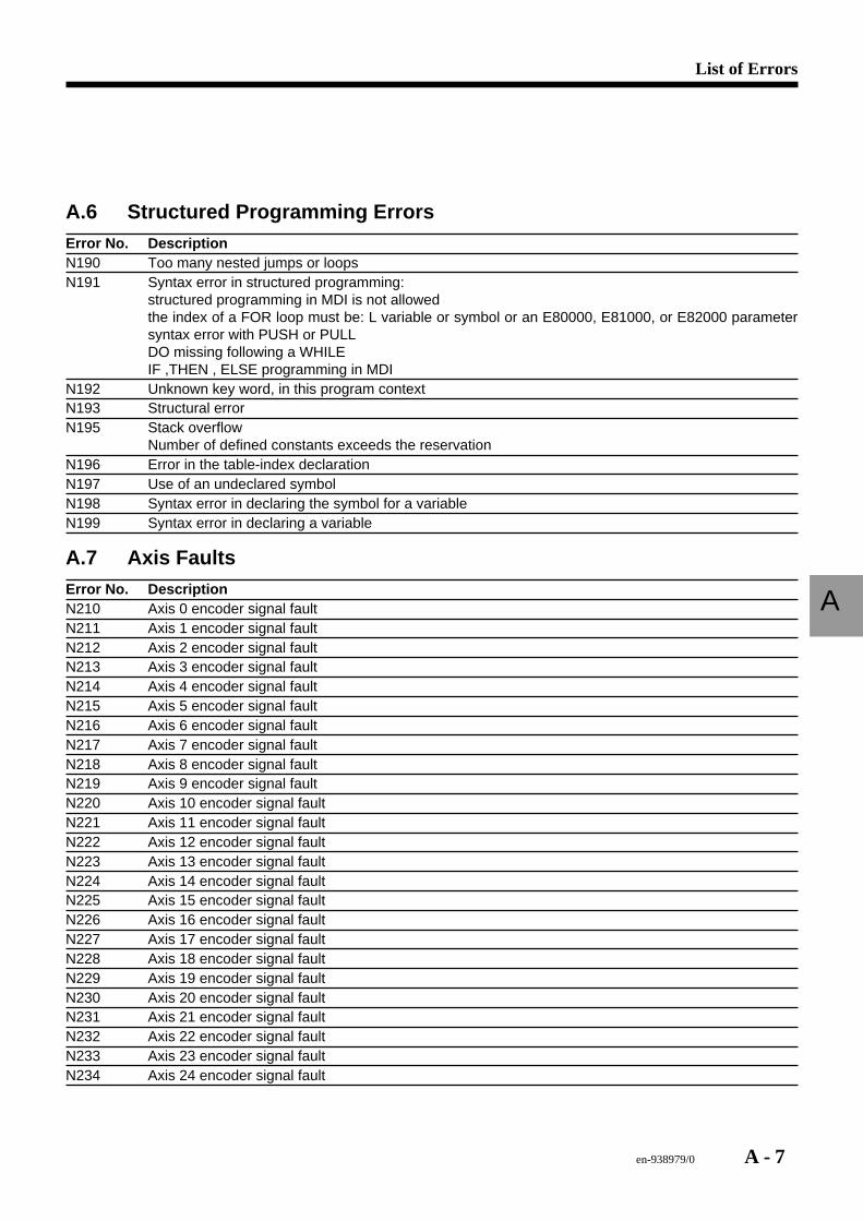
en-938979/0 A - 7
List of Errors
A
A.6 Structured Programming ErrorsError No. DescriptionN190 Too many nested jumps or loopsN191 Syntax error in structured programming:
structured programming in MDI is not allowedthe index of a FOR loop must be: L variable or symbol or an E80000, E81000, or E82000 parametersyntax error with PUSH or PULLDO missing following a WHILEIF ,THEN , ELSE programming in MDI
N192 Unknown key word, in this program contextN193 Structural errorN195 Stack overflow
Number of defined constants exceeds the reservationN196 Error in the table-index declarationN197 Use of an undeclared symbolN198 Syntax error in declaring the symbol for a variableN199 Syntax error in declaring a variable
A.7 Axis FaultsError No. DescriptionN210 Axis 0 encoder signal faultN211 Axis 1 encoder signal faultN212 Axis 2 encoder signal faultN213 Axis 3 encoder signal faultN214 Axis 4 encoder signal faultN215 Axis 5 encoder signal faultN216 Axis 6 encoder signal faultN217 Axis 7 encoder signal faultN218 Axis 8 encoder signal faultN219 Axis 9 encoder signal faultN220 Axis 10 encoder signal faultN221 Axis 11 encoder signal faultN222 Axis 12 encoder signal faultN223 Axis 13 encoder signal faultN224 Axis 14 encoder signal faultN225 Axis 15 encoder signal faultN226 Axis 16 encoder signal faultN227 Axis 17 encoder signal faultN228 Axis 18 encoder signal faultN229 Axis 19 encoder signal faultN230 Axis 20 encoder signal faultN231 Axis 21 encoder signal faultN232 Axis 22 encoder signal faultN233 Axis 23 encoder signal faultN234 Axis 24 encoder signal fault
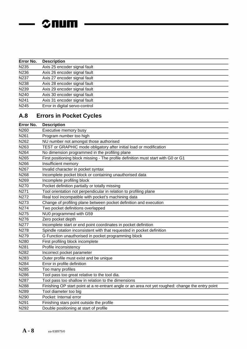
A - 8 en-938979/0
Error No. DescriptionN235 Axis 25 encoder signal faultN236 Axis 26 encoder signal faultN237 Axis 27 encoder signal faultN238 Axis 28 encoder signal faultN239 Axis 29 encoder signal faultN240 Axis 30 encoder signal faultN241 Axis 31 encoder signal faultN245 Error in digital servo-control
A.8 Errors in Pocket CyclesError No. DescriptionN260 Executive memory busyN261 Program number too highN262 NU number not amongst those authorisedN263 TEST or GRAPHIC mode obligatory after initial load or modificationN264 No dimension programmed in the profiling planeN265 First positioning block missing - The profile definition must start with G0 or G1N266 Insufficient memoryN267 Invalid character in pocket syntaxN268 Incomplete pocket block or containing unauthorised dataN269 Incomplete profiling blockN270 Pocket definition partially or totally missingN271 Tool orientation not perpendicular in relation to profiling planeN272 Real tool incompatible with pocket’s machining dataN273 Change of profiling plane between pocket definition and executionN274 Two pocket definitions overlappedN275 NU0 programmed with G59N276 Zero pocket depthN277 Incomplete start or end point coordinates in pocket definitionN278 Spindle rotation inconsistent with that requested in pocket definitionN279 G Function unauthorised in pocket programming blockN280 First profiling block incompleteN281 Profile inconsistencyN282 Incorrect pocket parameterN283 Outer profile must exist and be uniqueN284 Error in profile definitionN285 Too many profilesN286 Tool pass too great relative to the tool dia.N287 Tool pass too shallow in relation to the dimensionsN288 Finishing OP start point at a re-entrant angle or an area not yet roughed: change the entry pointN289 Tool diameter too bigN290 Pocket: Internal errorN291 Finishing stars point outside the profileN292 Double positioning at start of profile

Part 2
NUM DRIVE

en-938979/0 21 - 1
Axis Motors
21
21 Axis Motors
21.1 General 21 - 3
21.2 Characteristics and Performance 21 - 3
BMH Axis Motors 21 - 4General Characteristics 21 - 4Identification 21 - 4Detailed Characteristics 21 - 5BMH055 Axis Motors 21 - 6BMH055 Motor Characteristics Compared withOther BMH Motors 21 - 6Sensors 21 - 6
BMG Axis Motors 21 - 7General Characteristics 21 - 7Identification 21 - 7Detailed Characteristics 21 - 8
21.3 Sensors 21 - 9
21.4 Thermal Probes 21 - 11
21.5 Maintenance 21 - 1121.5.1 Checking Motor Insulation 21 - 1121.5.2 Measuring the Winding Impedance 21 - 11
21.6 Technical Characteristics of Brushless Motors 21 - 12
21.7 Technical Characteristics of BMS Motors 21 - 13
21.8 Technical Characteristics of BMH Motors 21 - 15

21 - 2 en-938979/0
en-938979/0 21 - 3
Axis Motors
21
21.1 GeneralNUM DRIVE axis motors are brushless motors.
These motors have samarium cobalt magnets. They feature a high power-to-weight ratio, a high dynamic speed rangeand a compact size. They can withstand a high applied overtorque without becoming demagnetised.
Several lines of motors are available:- BMS brushless servo-motors with or without brake (delivered until the end of 1993)- BMH brushless servo-motors with or without brake (available since September 1993)- BMG high-inertia brushless servo-motors without brake (available since April 1995)- BML compact brushless servo-motors without brake (available since November 1994)
These motors can be used with several different types of NUM DRIVE servo-drives with sinusoidal and flux vectorcontrol.
21.2 Characteristics and PerformanceThe detailed mechanical characteristics of the axis motors (overall dimensions, shaft loads) are given in NUM DRIVECatalogue en-938919/3, Chapter 1.
For interfacing the motors and associated servo-drives, refer to the installation and maintenance manuals for theservo-drives:
UAC Manual 738F003/C
MNDA Manual 738F006/E
MDLA Manual 738F008/C
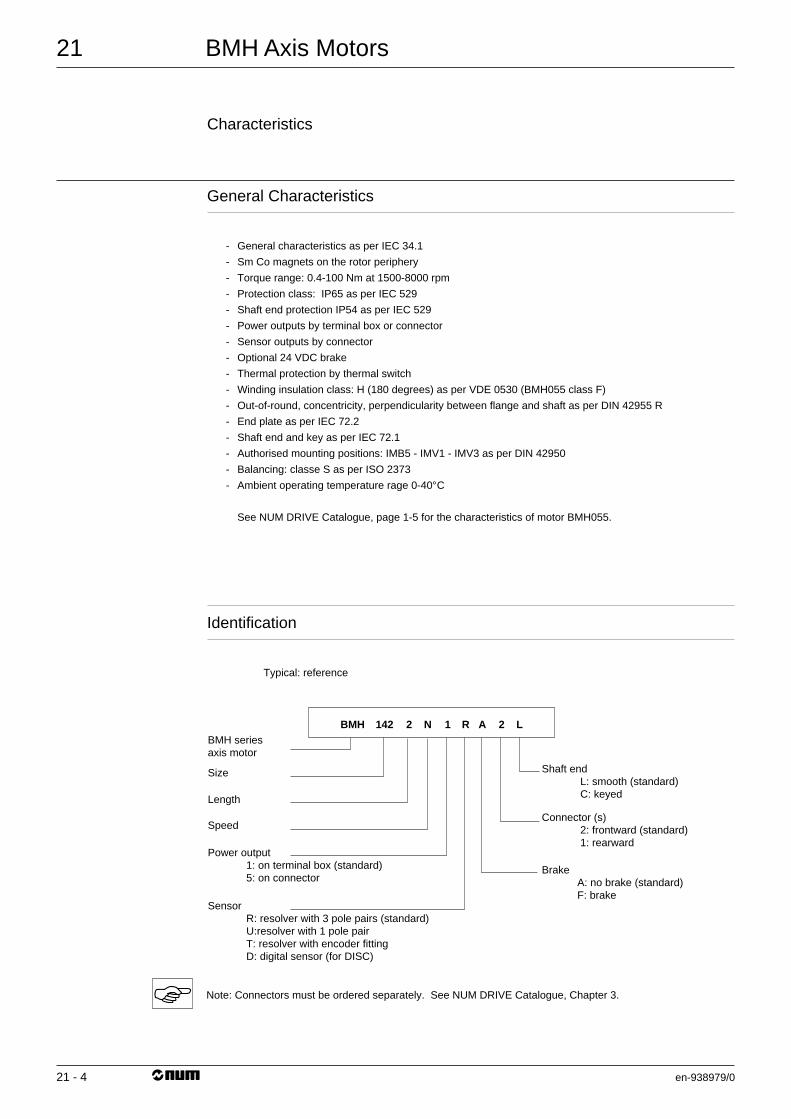
21
21 - 4
BMH Axis Motors
en-938979/0
Characteristics
General Characteristics
- General characteristics as per IEC 34.1
- Sm Co magnets on the rotor periphery
- Torque range: 0.4-100 Nm at 1500-8000 rpm
- Protection class: IP65 as per IEC 529
- Shaft end protection IP54 as per IEC 529
- Power outputs by terminal box or connector
- Sensor outputs by connector
- Optional 24 VDC brake
- Thermal protection by thermal switch
- Winding insulation class: H (180 degrees) as per VDE 0530 (BMH055 class F)
- Out-of-round, concentricity, perpendicularity between flange and shaft as per DIN 42955 R
- End plate as per IEC 72.2
- Shaft end and key as per IEC 72.1
- Authorised mounting positions: IMB5 - IMV1 - IMV3 as per DIN 42950
- Balancing: classe S as per ISO 2373
- Ambient operating temperature rage 0-40°C
See NUM DRIVE Catalogue, page 1-5 for the characteristics of motor BMH055.
Identification
Typical: reference
Shaft end L: smooth (standard) C: keyed
BMH series axis motor
Size
Length
Speed
Power output 1: on terminal box (standard) 5: on connector
Sensor R: resolver with 3 pole pairs (standard) U:resolver with 1 pole pair T: resolver with encoder fitting D: digital sensor (for DISC)
Connector (s) 2: frontward (standard) 1: rearward
Brake A: no brake (standard) F: brake
L2AR1N2142BMH
Note: Connectors must be ordered separately. See NUM DRIVE Catalogue, Chapter 3.
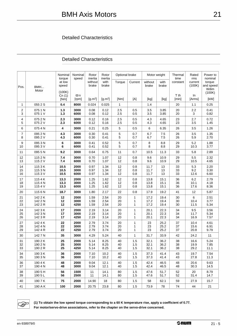
BMH Axis Motors
en-938979/0
21
21 - 5
Detailed Characteristics
Detailed Characteristics
1
23
45
6
78
910
11
1213
141516
171819
20
212223
242526
272829
30
313233
3435
3637
3839
40
41
055 2 S
075 1 N075 1 V
075 2 N075 2 V
075 4 N
095 2 N095 2 V
095 3 N095 3 V
095 5 N
115 2 N115 2 V
115 3 K115 3 N115 3 V
115 4 K115 4 N115 4 V
115 6 N
142 2 K142 2 N142 2 R
142 3 K142 3 N142 3 R
142 4 K142 4 N142 4 R
142 7 N
190 2 K190 2 N190 2 R
190 3 K190 3 N
190 4 K190 4 N
190 5 H190 5 L
190 7 K
190 A K
0.4
1.31.3
2.32.3
4
4.34.3
66
9.2
7.47.4
10.510.510.5
13.313.313.3
18.7
121212
171717
222222
35
252525
3636
4848
5656
75
100
0.024
0.080.08
0.120.12
0.21
0.300.30
0.410.41
0.64
0.700.70
0.970.970.97
1.251.251.25
1.80
1.591.591.59
2.192.192.19
2.792.792.79
4.29
5.145.145.14
7.107.10
9.049.04
1111
14.90
20.75
0.025
0.120.12
0.160.16
0.25
0.410.41
0.520.52
0.75
1.071.07
1.341.341.34
1.621.621.62
2.17
2.542.542.54
3.143.143.14
3.743.743.74
5.24
8.258.258.25
10.210.2
12.112.1
14.114.1
18
23.8
1
2.52.5
2.52.5
5
55
55
11
1212
121212
121212
22
202020
202020
202020
40
404040
4040
4040
8080
80
80
1.4
3.53.5
4.34.3
6
6.76.7
88
10.5
9.69.6
11.711.711.7
13.813.813.8
17.9
17.217.217.2
20.120.120.1
232323
31.7
32.132.132.1
37.337.3
42.442.4
47.647.6
58
73.9
20
2020
2323
26
2626
2929
33
2929
333333
363636
41
303030
343434
373737
42
383838
4343
4848
5252
59
74
1.1
2.23
2.73.5
3.5
3.55.9
5.210.3
5.8
5.510.5
5.39.212.6
6.210.117.6
12
610.411.5
9.511.716.9
10.415.620.8
24.2
16.619.929.2
19.727.8
20.630.3
2031.4
27.9
44
0.25
0.410.82
0.721.45
1.26
1.352.70
1.883.77
2.89
2.324.65
2.203.306.60
2.794.188.36
5.87
2.513.775.34
3.565.347.57
4.616.919.79
11
5.247.8511.1
7.5411.3
9.6314.5
8.7914.7
15.7
21
0.50.5
0.50.5
0.5
0.70.7
0.70.7
0.7
0.80.8
0.80.80.8
0.80.80.8
0.8
111
111
111
1
1.51.51.5
1.51.5
1.51.5
1.51.5
1.5
1.5
3.853.85
4.654.65
6.35
7.57.5
8.88.8
11.3
10.910.9
131313
15.115.115.1
19.2
19.419.419.4
22.322.322.3
25.225.225.2
33.9
36.236.236.2
41.441.4
46.546.5
51.751.7
62.1
78
8000
30006000
30006000
3000
30006000
30006000
3000
30006000
200030006000
200030006000
3000
200030004250
200030004250
200030004250
3000
200030004250
20003000
20003000
15002500
2000
2000
Pos. BMH...Motor
Nominaltorqueat lowspeed
Nominalspeed
Rotorinertiawithoutbrake
Optional brake
Torque Current withoutbrake
withbrake
(100K)Cn (1)[Nm]
ω n[rpm] [g.m2]
Rotorinertiawith
brake
[g.m2]
Thermaltime
constant
Ratedrms
current(100K)
Motor weight Power tonominaltorque
and speedWdim(100K)
T th[min]
In[Arms][kg][kg] [kW][Nm] [A]
(1) To obtain the low speed torque corresponding to a 60 K temperature rise, apply a coefficient of 0.77.
For motor/servo-drive associations, refer to the chapter on the servo-drive concerned.
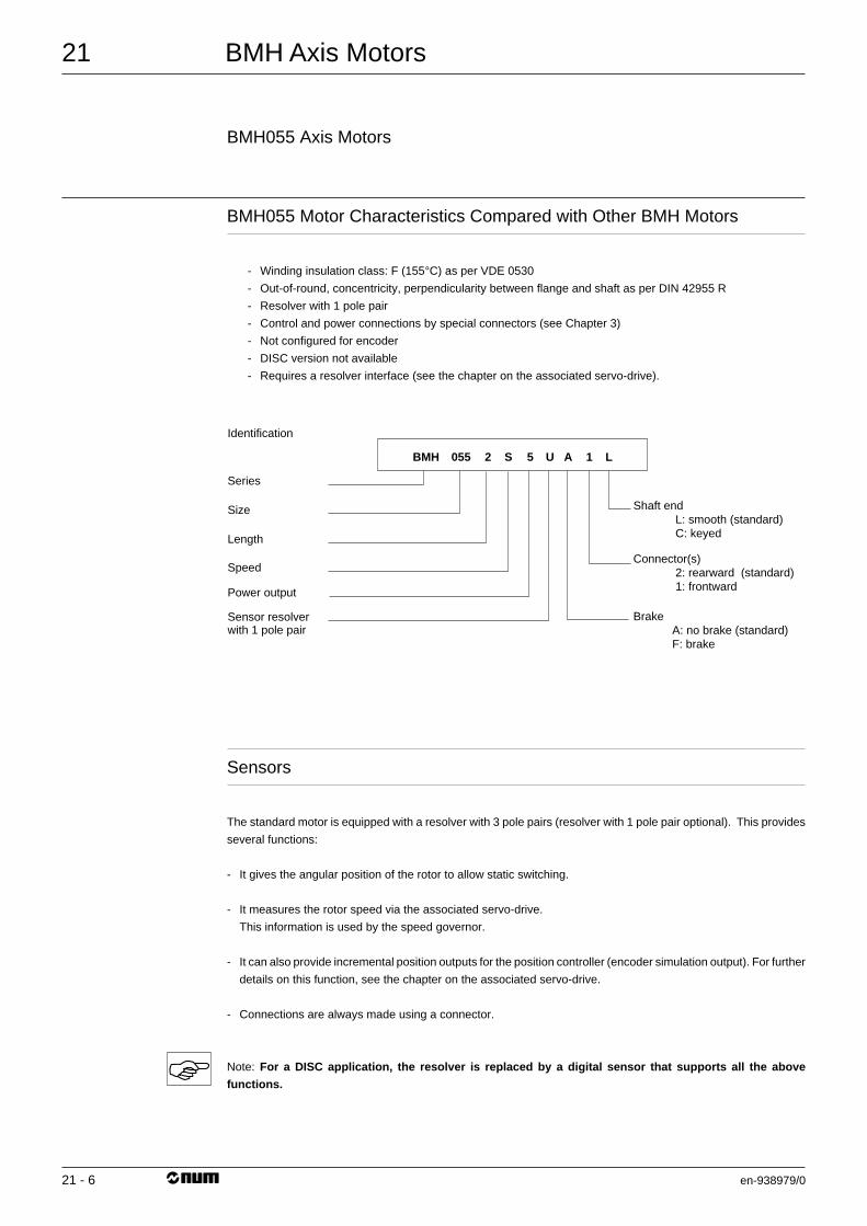
21
21 - 6
BMH Axis Motors
en-938979/0
BMH055 Axis Motors
BMH055 Motor Characteristics Compared with Other BMH Motors
- Winding insulation class: F (155°C) as per VDE 0530
- Out-of-round, concentricity, perpendicularity between flange and shaft as per DIN 42955 R
- Resolver with 1 pole pair
- Control and power connections by special connectors (see Chapter 3)
- Not configured for encoder
- DISC version not available
- Requires a resolver interface (see the chapter on the associated servo-drive).
Shaft end L: smooth (standard) C: keyed
Series
Size
Identification
Length
Speed
Power output
Sensor resolver with 1 pole pair
Connector(s) 2: rearward (standard) 1: frontward
Brake A: no brake (standard) F: brake
L1AU5S2055BMH
Sensors
The standard motor is equipped with a resolver with 3 pole pairs (resolver with 1 pole pair optional). This provides
several functions:
- It gives the angular position of the rotor to allow static switching.
- It measures the rotor speed via the associated servo-drive.
This information is used by the speed governor.
- It can also provide incremental position outputs for the position controller (encoder simulation output). For further
details on this function, see the chapter on the associated servo-drive.
- Connections are always made using a connector.
Note: For a DISC application, the resolver is replaced by a digital sensor that supports all the above
functions.
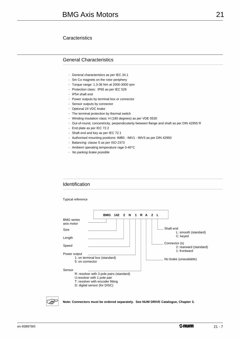
BMG Axis Motors
en-938979/0
21
21 - 7
Caracteristics
General Characteristics
- General characteristics as per IEC 34.1
- Sm Co magnets on the rotor periphery
- Torque range: 1.3-36 Nm at 2000-3000 rpm
- Protection class: IP65 as per IEC 529
- IP54 shaft end
- Power outputs by terminal box or connector
- Sensor outputs by connector
- Optional 24 VDC brake
- The terminal protection by thermal switch
- Winding insulation class: H (180 degrees) as per VDE 0530
- Out-of-round, concentricity, perpendicularity between flange and shaft as per DIN 42955 R
- End plate as per IEC 72.2
- Shaft end and key as per IEC 72.1
- Authorised mounting positions: IMB5 - IMV1 - IMV3 as per DIN 42950
- Balancing: classe S as per ISO 2373
- Ambient operating temperature rage 0-40°C
- No parking brake possible
Identification
Typical reference
Shaft end L: smooth (standard) C: keyed
BMG series axis motor
Size
Length
Speed
Power output 1: on terminal box (standard) 5: on connector
Sensor R: resolver with 3 pole pairs (standard) U:resolver with 1 pole pair T: resolver with encoder fitting D: digital sensor (for DISC)
Connector (s) 2: rearward (standard) 1: frontward
No brake (unavailable)
L2AR1N2142BMG
Note: Connectors must be ordered separately. See NUM DRIVE Catalogue, Chapter 3.
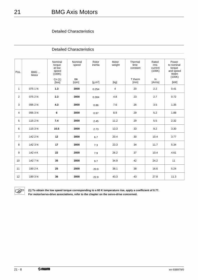
21
21 - 8
BMG Axis Motors
en-938979/0
Detailed Characteristics
Detailed Characteristics
1
2
3
4
5
6
7
8
9
10
11
12
075 1 N
075 2 N
095 2 N
095 3 N
115 2 N
115 3 N
142 2 N
142 3 N
142 4 K
142 7 N
190 2 K
190 3 N
1.3
2.3
4.3
6
7.4
10.5
12
17
22
35
25
36
0.254
0.304
0.86
0.97
2.45
2.73
6.7
7.3
7.9
9.7
20.9
22.9
4
4.8
7.6
8.9
11.2
13.3
20.4
23.3
26.2
34.9
38.1
43.3
20
23
26
29
29
33
30
34
37
42
38
43
2.2
2.7
3.5
5.2
5.5
9.2
10.4
11.7
10.4
24.2
16.6
27.8
0.41
0.72
1.35
1.88
2.32
3.30
3.77
5.34
4.61
11
5.24
11.3
3000
3000
3000
3000
3000
3000
3000
3000
2000
3000
2000
3000
Pos. BMG ... Motor
Nominal torque at low speed(100K)
Nominalspeed
Rotorinertia
Cn (1)[Nm]
ωn[rpm] [g.m2]
Thermal time
constant
Rated rms
current(100K)
Motor weight
Power to nominal
torque and speed
Wdim(100K)
T therm[min]
In[Arms][kg] [kW]
(1) To obtain the low speed torque corresponding to a 60 K temperature rise, apply a coefficient of 0.77.
For motor/servo-drive associations, refer to the chapter on the servo-drive concerned.
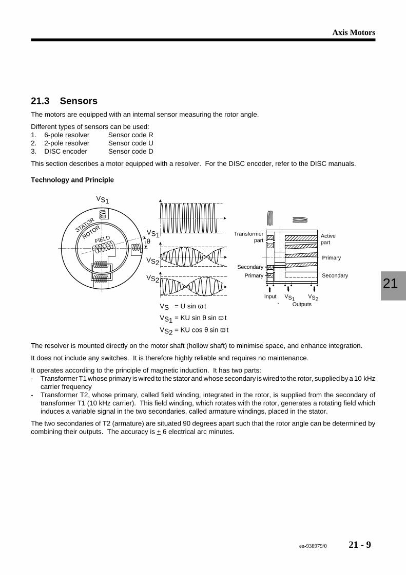
en-938979/0 21 - 9
Axis Motors
21
21.3 SensorsThe motors are equipped with an internal sensor measuring the rotor angle.
Different types of sensors can be used:1. 6-pole resolver Sensor code R2. 2-pole resolver Sensor code U3. DISC encoder Sensor code D
This section describes a motor equipped with a resolver. For the DISC encoder, refer to the DISC manuals.
Technology and Principle
yyyyyzzzzz yyyyyyzzzzz||||||||||||yyyyyyyyyyzzzzzzzzz|||||||||yyyyyyyyyyyyyzzzzzzzzzzzz||||||yyyyyyyyyyyyyyzzzzzzzzzzzzzzyyyyyzzzzz yyyyzzzzyyyyyzzzzzVS1
VS1
VS2VS = U sin ω t
VS1 = KU sin θ sin ω t
VS2 = KU cos θ sin ω t
VS2
VS2
FIELDSTATOR
ROTOR
θTransformer
part
Secondary
SecondaryPrimary
Primary
Activepart
InputOutputs
VS1
The resolver is mounted directly on the motor shaft (hollow shaft) to minimise space, and enhance integration.
It does not include any switches. It is therefore highly reliable and requires no maintenance.
It operates according to the principle of magnetic induction. It has two parts:- Transformer T1 whose primary is wired to the stator and whose secondary is wired to the rotor, supplied by a 10 kHz
carrier frequency- Transformer T2, whose primary, called field winding, integrated in the rotor, is supplied from the secondary of
transformer T1 (10 kHz carrier). This field winding, which rotates with the rotor, generates a rotating field whichinduces a variable signal in the two secondaries, called armature windings, placed in the stator.
The two secondaries of T2 (armature) are situated 90 degrees apart such that the rotor angle can be determined bycombining their outputs. The accuracy is + 6 electrical arc minutes.
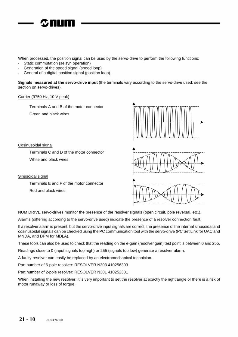
21 - 10 en-938979/0
When processed, the position signal can be used by the servo-drive to perform the following functions:- Static commutation (selsyn operation)- Generation of the speed signal (speed loop)- General of a digital position signal (position loop).
Signals measured at the servo-drive input (the terminals vary according to the servo-drive used; see thesection on servo-drives).
Carrier (9750 Hz, 10 V peak)
Terminals A and B of the motor connector
Green and black wires
Cosinusoidal signal
Terminals C and D of the motor connector
White and black wires
Sinusoidal signal
Terminals E and F of the motor connector
Red and black wires
NUM DRIVE servo-drives monitor the presence of the resolver signals (open circuit, pole reversal, etc.).
Alarms (differing according to the servo-drive used) indicate the presence of a resolver connection fault.
If a resolver alarm is present, but the servo-drive input signals are correct, the presence of the internal sinusoidal andcosinusoidal signals can be checked using the PC communication tool with the servo-drive (PC Set Link for UAC andMNDA, and DPM for MDLA).
These tools can also be used to check that the reading on the e-gain (resolver gain) test point is between 0 and 255.
Readings close to 0 (input signals too high) or 255 (signals too low) generate a resolver alarm.
A faulty resolver can easily be replaced by an electromechanical technician.
Part number of 6-pole resolver: RESOLVER N303 410256303
Part number of 2-pole resolver: RESOLVER N301 410252301
When installing the new resolver, it is very important to set the resolver at exactly the right angle or there is a risk ofmotor runaway or loss of torque.
en-938979/0 21 - 11
Axis Motors
21
A setting procedure is described in the Installation and Maintenance Manuals for the associated servo-drives.
Manual 738E003/C for UAC
Manual 738E006/E for MNDA
Manual 738E008/C for MDLA
This procedure, although simple, requires use of the SPM or MPM communication software, a PC and a digitalmultimeter.
After replacement of the motor, the resolver or its wire, always repeat the automatic calibration procedure with PC SetLink (SPM software packages).
21.4 Thermal ProbesThe motor temperature is monitored by a thermal switch mounted on the motor frame. If it fails, this thermal switchis very easy to replace. It is located inside the motor terminal box.
For motor:
BMS : TERMF11160C 410211160 (160 °C)
BMH/BMG : TERMF1150C 410211150 (150 °C)
BMH DISC : TERMF190C 410211090 (90 °C)
21.5 MaintenanceNUM DRIVE brushless motors have life-lubricated bearings and require no maintenance.
If repeated Overcurrent alarms are detected by the servo-drive, check the winding impedance and insulation from theprotective earth.
21.5.1 Checking Motor Insulation
The insulation resistance must be measured by a special insulation tester (e.g. Megger) which can output 1000 VDC.
Disconnect the motor cables. Earth the thermal switch and the brake if any.
Interconnect the three phases of the motor. Then apply the test voltage to the windings and earth.
The insulation resistance must be > 2 MΩ
If the measured value is lower, check for moisture inside the motor power connections, before deciding that thewindings are faulty.
21.5.2 Measuring the Winding Impedance
The motor winding impedance is generally very low (a few tenths of an ohm to a few ohms, depending on the motor).It is therefore difficult to measure with a conventional multimeter.
21 - 12 en-938979/0
21.6 Technical Characteristics of Brushless Motors(Table headings on following pages)
Cnom : Nominal torque (Nm)
wnom : Nominal speed (rpm)
Wdim : Power at nominal torque and speed Wdim = Cnom x wnom x 2P/60
Inom : Rated current (at nominal torque) (Arms)
Kt : Torque constant = Cnom/Inom (Nm/A)
Ef : Electromotive force of a winding (V/1000 rpm)
Jr : Motor inertia (g.m2)
Ke : Speed constant = Ef/w(V.s)
P = Cw = Kt.lf.wIf: Current in a winding = phase current (wye coupling)Ef: Voltage in a windingU: Voltage between phases = Vf. 3 (wye coupling)
P = U.lf.cos∅. 3 = Ef. 3 .If. 3 = 3.Ef.If = 3.Ke.w.lf (neglecting the power factor)Therefore Ke = Kt / 3
Rf : Winding resistance (mohm) (value at 20°C)
Lf : Winding inductance (mH)
Te : Electrical time constant (ms) = Lf/Rf
Tm : Mechanical time constant (ms)
Tth : Thermal time constant (min)
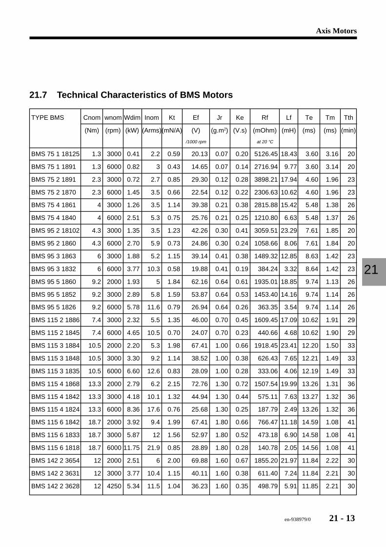
en-938979/0 21 - 13
Axis Motors
21
21.7 Technical Characteristics of BMS Motors
TYPE BMS Cnom wnom Wdim Inom Kt Ef Jr Ke Rf Lf Te Tm Tth
(Nm) (rpm) (kW) (Arms)(mN/A) (V) (g.m2) (V.s) (mOhm) (mH) (ms) (ms) (min)
/1000 rpm at 20 °C
BMS 75 1 18125 1.3 3000 0.41 2.2 0.59 20.13 0.07 0.20 5126.45 18.43 3.60 3.16 20
BMS 75 1 1891 1.3 6000 0.82 3 0.43 14.65 0.07 0.14 2716.94 9.77 3.60 3.14 20
BMS 75 2 1891 2.3 3000 0.72 2.7 0.85 29.30 0.12 0.28 3898.21 17.94 4.60 1.96 23
BMS 75 2 1870 2.3 6000 1.45 3.5 0.66 22.54 0.12 0.22 2306.63 10.62 4.60 1.96 23
BMS 75 4 1861 4 3000 1.26 3.5 1.14 39.38 0.21 0.38 2815.88 15.42 5.48 1.38 26
BMS 75 4 1840 4 6000 2.51 5.3 0.75 25.76 0.21 0.25 1210.80 6.63 5.48 1.37 26
BMS 95 2 18102 4.3 3000 1.35 3.5 1.23 42.26 0.30 0.41 3059.51 23.29 7.61 1.85 20
BMS 95 2 1860 4.3 6000 2.70 5.9 0.73 24.86 0.30 0.24 1058.66 8.06 7.61 1.84 20
BMS 95 3 1863 6 3000 1.88 5.2 1.15 39.14 0.41 0.38 1489.32 12.85 8.63 1.42 23
BMS 95 3 1832 6 6000 3.77 10.3 0.58 19.88 0.41 0.19 384.24 3.32 8.64 1.42 23
BMS 95 5 1860 9.2 2000 1.93 5 1.84 62.16 0.64 0.61 1935.01 18.85 9.74 1.13 26
BMS 95 5 1852 9.2 3000 2.89 5.8 1.59 53.87 0.64 0.53 1453.40 14.16 9.74 1.14 26
BMS 95 5 1826 9.2 6000 5.78 11.6 0.79 26.94 0.64 0.26 363.35 3.54 9.74 1.14 26
BMS 115 2 1886 7.4 3000 2.32 5.5 1.35 46.00 0.70 0.45 1609.45 17.09 10.62 1.91 29
BMS 115 2 1845 7.4 6000 4.65 10.5 0.70 24.07 0.70 0.23 440.66 4.68 10.62 1.90 29
BMS 115 3 1884 10.5 2000 2.20 5.3 1.98 67.41 1.00 0.66 1918.45 23.41 12.20 1.50 33
BMS 115 3 1848 10.5 3000 3.30 9.2 1.14 38.52 1.00 0.38 626.43 7.65 12.21 1.49 33
BMS 115 3 1835 10.5 6000 6.60 12.6 0.83 28.09 1.00 0.28 333.06 4.06 12.19 1.49 33
BMS 115 4 1868 13.3 2000 2.79 6.2 2.15 72.76 1.30 0.72 1507.54 19.99 13.26 1.31 36
BMS 115 4 1842 13.3 3000 4.18 10.1 1.32 44.94 1.30 0.44 575.11 7.63 13.27 1.32 36
BMS 115 4 1824 13.3 6000 8.36 17.6 0.76 25.68 1.30 0.25 187.79 2.49 13.26 1.32 36
BMS 115 6 1842 18.7 2000 3.92 9.4 1.99 67.41 1.80 0.66 766.47 11.18 14.59 1.08 41
BMS 115 6 1833 18.7 3000 5.87 12 1.56 52.97 1.80 0.52 473.18 6.90 14.58 1.08 41
BMS 115 6 1818 18.7 6000 11.75 21.9 0.85 28.89 1.80 0.28 140.78 2.05 14.56 1.08 41
BMS 142 2 3654 12 2000 2.51 6 2.00 69.88 1.60 0.67 1855.20 21.97 11.84 2.22 30
BMS 142 2 3631 12 3000 3.77 10.4 1.15 40.11 1.60 0.38 611.40 7.24 11.84 2.21 30
BMS 142 2 3628 12 4250 5.34 11.5 1.04 36.23 1.60 0.35 498.79 5.91 11.85 2.21 30
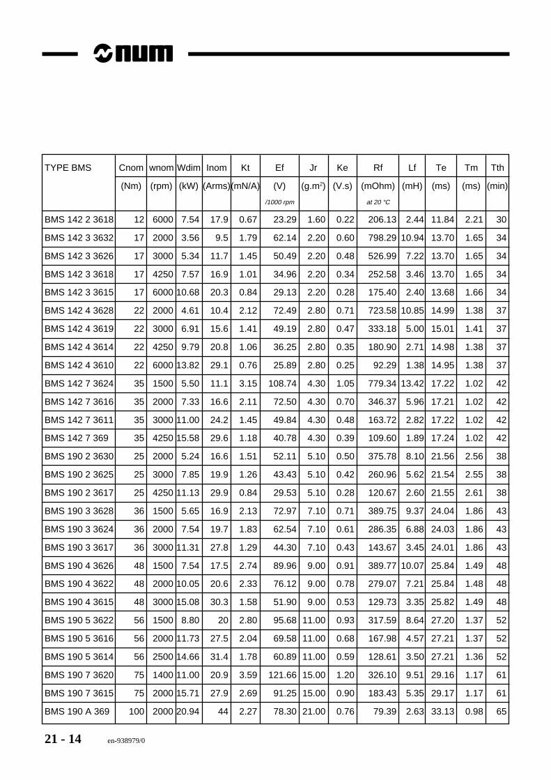
21 - 14 en-938979/0
TYPE BMS Cnom wnom Wdim Inom Kt Ef Jr Ke Rf Lf Te Tm Tth
(Nm) (rpm) (kW) (Arms)(mN/A) (V) (g.m2) (V.s) (mOhm) (mH) (ms) (ms) (min)
/1000 rpm at 20 °C
BMS 142 2 3618 12 6000 7.54 17.9 0.67 23.29 1.60 0.22 206.13 2.44 11.84 2.21 30
BMS 142 3 3632 17 2000 3.56 9.5 1.79 62.14 2.20 0.60 798.29 10.94 13.70 1.65 34
BMS 142 3 3626 17 3000 5.34 11.7 1.45 50.49 2.20 0.48 526.99 7.22 13.70 1.65 34
BMS 142 3 3618 17 4250 7.57 16.9 1.01 34.96 2.20 0.34 252.58 3.46 13.70 1.65 34
BMS 142 3 3615 17 6000 10.68 20.3 0.84 29.13 2.20 0.28 175.40 2.40 13.68 1.66 34
BMS 142 4 3628 22 2000 4.61 10.4 2.12 72.49 2.80 0.71 723.58 10.85 14.99 1.38 37
BMS 142 4 3619 22 3000 6.91 15.6 1.41 49.19 2.80 0.47 333.18 5.00 15.01 1.41 37
BMS 142 4 3614 22 4250 9.79 20.8 1.06 36.25 2.80 0.35 180.90 2.71 14.98 1.38 37
BMS 142 4 3610 22 6000 13.82 29.1 0.76 25.89 2.80 0.25 92.29 1.38 14.95 1.38 37
BMS 142 7 3624 35 1500 5.50 11.1 3.15 108.74 4.30 1.05 779.34 13.42 17.22 1.02 42
BMS 142 7 3616 35 2000 7.33 16.6 2.11 72.50 4.30 0.70 346.37 5.96 17.21 1.02 42
BMS 142 7 3611 35 3000 11.00 24.2 1.45 49.84 4.30 0.48 163.72 2.82 17.22 1.02 42
BMS 142 7 369 35 4250 15.58 29.6 1.18 40.78 4.30 0.39 109.60 1.89 17.24 1.02 42
BMS 190 2 3630 25 2000 5.24 16.6 1.51 52.11 5.10 0.50 375.78 8.10 21.56 2.56 38
BMS 190 2 3625 25 3000 7.85 19.9 1.26 43.43 5.10 0.42 260.96 5.62 21.54 2.55 38
BMS 190 2 3617 25 4250 11.13 29.9 0.84 29.53 5.10 0.28 120.67 2.60 21.55 2.61 38
BMS 190 3 3628 36 1500 5.65 16.9 2.13 72.97 7.10 0.71 389.75 9.37 24.04 1.86 43
BMS 190 3 3624 36 2000 7.54 19.7 1.83 62.54 7.10 0.61 286.35 6.88 24.03 1.86 43
BMS 190 3 3617 36 3000 11.31 27.8 1.29 44.30 7.10 0.43 143.67 3.45 24.01 1.86 43
BMS 190 4 3626 48 1500 7.54 17.5 2.74 89.96 9.00 0.91 389.77 10.07 25.84 1.49 48
BMS 190 4 3622 48 2000 10.05 20.6 2.33 76.12 9.00 0.78 279.07 7.21 25.84 1.48 48
BMS 190 4 3615 48 3000 15.08 30.3 1.58 51.90 9.00 0.53 129.73 3.35 25.82 1.49 48
BMS 190 5 3622 56 1500 8.80 20 2.80 95.68 11.00 0.93 317.59 8.64 27.20 1.37 52
BMS 190 5 3616 56 2000 11.73 27.5 2.04 69.58 11.00 0.68 167.98 4.57 27.21 1.37 52
BMS 190 5 3614 56 2500 14.66 31.4 1.78 60.89 11.00 0.59 128.61 3.50 27.21 1.36 52
BMS 190 7 3620 75 1400 11.00 20.9 3.59 121.66 15.00 1.20 326.10 9.51 29.16 1.17 61
BMS 190 7 3615 75 2000 15.71 27.9 2.69 91.25 15.00 0.90 183.43 5.35 29.17 1.17 61
BMS 190 A 369 100 2000 20.94 44 2.27 78.30 21.00 0.76 79.39 2.63 33.13 0.98 65
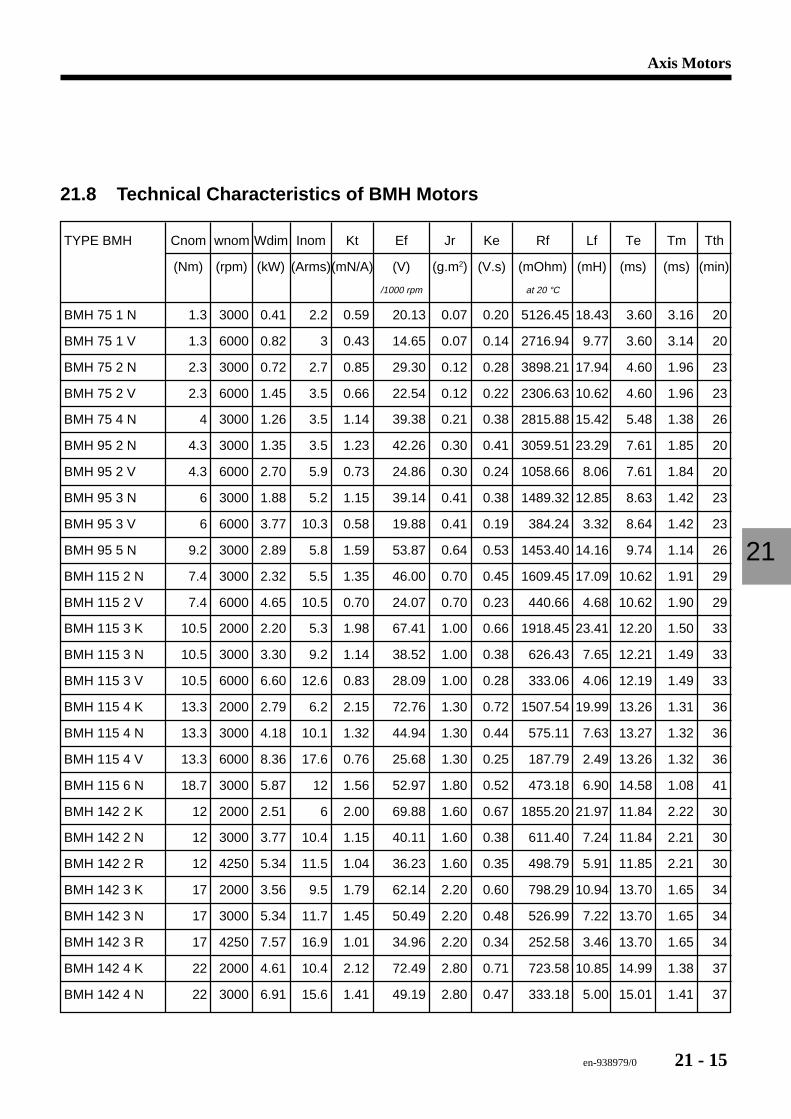
en-938979/0 21 - 15
Axis Motors
21
21.8 Technical Characteristics of BMH Motors
TYPE BMH Cnom wnom Wdim Inom Kt Ef Jr Ke Rf Lf Te Tm Tth
(Nm) (rpm) (kW) (Arms)(mN/A) (V) (g.m2) (V.s) (mOhm) (mH) (ms) (ms) (min)
/1000 rpm at 20 °C
BMH 75 1 N 1.3 3000 0.41 2.2 0.59 20.13 0.07 0.20 5126.45 18.43 3.60 3.16 20
BMH 75 1 V 1.3 6000 0.82 3 0.43 14.65 0.07 0.14 2716.94 9.77 3.60 3.14 20
BMH 75 2 N 2.3 3000 0.72 2.7 0.85 29.30 0.12 0.28 3898.21 17.94 4.60 1.96 23
BMH 75 2 V 2.3 6000 1.45 3.5 0.66 22.54 0.12 0.22 2306.63 10.62 4.60 1.96 23
BMH 75 4 N 4 3000 1.26 3.5 1.14 39.38 0.21 0.38 2815.88 15.42 5.48 1.38 26
BMH 95 2 N 4.3 3000 1.35 3.5 1.23 42.26 0.30 0.41 3059.51 23.29 7.61 1.85 20
BMH 95 2 V 4.3 6000 2.70 5.9 0.73 24.86 0.30 0.24 1058.66 8.06 7.61 1.84 20
BMH 95 3 N 6 3000 1.88 5.2 1.15 39.14 0.41 0.38 1489.32 12.85 8.63 1.42 23
BMH 95 3 V 6 6000 3.77 10.3 0.58 19.88 0.41 0.19 384.24 3.32 8.64 1.42 23
BMH 95 5 N 9.2 3000 2.89 5.8 1.59 53.87 0.64 0.53 1453.40 14.16 9.74 1.14 26
BMH 115 2 N 7.4 3000 2.32 5.5 1.35 46.00 0.70 0.45 1609.45 17.09 10.62 1.91 29
BMH 115 2 V 7.4 6000 4.65 10.5 0.70 24.07 0.70 0.23 440.66 4.68 10.62 1.90 29
BMH 115 3 K 10.5 2000 2.20 5.3 1.98 67.41 1.00 0.66 1918.45 23.41 12.20 1.50 33
BMH 115 3 N 10.5 3000 3.30 9.2 1.14 38.52 1.00 0.38 626.43 7.65 12.21 1.49 33
BMH 115 3 V 10.5 6000 6.60 12.6 0.83 28.09 1.00 0.28 333.06 4.06 12.19 1.49 33
BMH 115 4 K 13.3 2000 2.79 6.2 2.15 72.76 1.30 0.72 1507.54 19.99 13.26 1.31 36
BMH 115 4 N 13.3 3000 4.18 10.1 1.32 44.94 1.30 0.44 575.11 7.63 13.27 1.32 36
BMH 115 4 V 13.3 6000 8.36 17.6 0.76 25.68 1.30 0.25 187.79 2.49 13.26 1.32 36
BMH 115 6 N 18.7 3000 5.87 12 1.56 52.97 1.80 0.52 473.18 6.90 14.58 1.08 41
BMH 142 2 K 12 2000 2.51 6 2.00 69.88 1.60 0.67 1855.20 21.97 11.84 2.22 30
BMH 142 2 N 12 3000 3.77 10.4 1.15 40.11 1.60 0.38 611.40 7.24 11.84 2.21 30
BMH 142 2 R 12 4250 5.34 11.5 1.04 36.23 1.60 0.35 498.79 5.91 11.85 2.21 30
BMH 142 3 K 17 2000 3.56 9.5 1.79 62.14 2.20 0.60 798.29 10.94 13.70 1.65 34
BMH 142 3 N 17 3000 5.34 11.7 1.45 50.49 2.20 0.48 526.99 7.22 13.70 1.65 34
BMH 142 3 R 17 4250 7.57 16.9 1.01 34.96 2.20 0.34 252.58 3.46 13.70 1.65 34
BMH 142 4 K 22 2000 4.61 10.4 2.12 72.49 2.80 0.71 723.58 10.85 14.99 1.38 37
BMH 142 4 N 22 3000 6.91 15.6 1.41 49.19 2.80 0.47 333.18 5.00 15.01 1.41 37
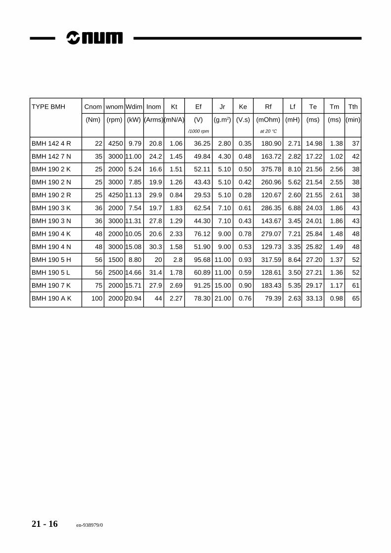
21 - 16 en-938979/0
TYPE BMH Cnom wnom Wdim Inom Kt Ef Jr Ke Rf Lf Te Tm Tth
(Nm) (rpm) (kW) (Arms)(mN/A) (V) (g.m2) (V.s) (mOhm) (mH) (ms) (ms) (min)
/1000 rpm at 20 °C
BMH 142 4 R 22 4250 9.79 20.8 1.06 36.25 2.80 0.35 180.90 2.71 14.98 1.38 37
BMH 142 7 N 35 3000 11.00 24.2 1.45 49.84 4.30 0.48 163.72 2.82 17.22 1.02 42
BMH 190 2 K 25 2000 5.24 16.6 1.51 52.11 5.10 0.50 375.78 8.10 21.56 2.56 38
BMH 190 2 N 25 3000 7.85 19.9 1.26 43.43 5.10 0.42 260.96 5.62 21.54 2.55 38
BMH 190 2 R 25 4250 11.13 29.9 0.84 29.53 5.10 0.28 120.67 2.60 21.55 2.61 38
BMH 190 3 K 36 2000 7.54 19.7 1.83 62.54 7.10 0.61 286.35 6.88 24.03 1.86 43
BMH 190 3 N 36 3000 11.31 27.8 1.29 44.30 7.10 0.43 143.67 3.45 24.01 1.86 43
BMH 190 4 K 48 2000 10.05 20.6 2.33 76.12 9.00 0.78 279.07 7.21 25.84 1.48 48
BMH 190 4 N 48 3000 15.08 30.3 1.58 51.90 9.00 0.53 129.73 3.35 25.82 1.49 48
BMH 190 5 H 56 1500 8.80 20 2.8 95.68 11.00 0.93 317.59 8.64 27.20 1.37 52
BMH 190 5 L 56 2500 14.66 31.4 1.78 60.89 11.00 0.59 128.61 3.50 27.21 1.36 52
BMH 190 7 K 75 2000 15.71 27.9 2.69 91.25 15.00 0.90 183.43 5.35 29.17 1.17 61
BMH 190 A K 100 2000 20.94 44 2.27 78.30 21.00 0.76 79.39 2.63 33.13 0.98 65
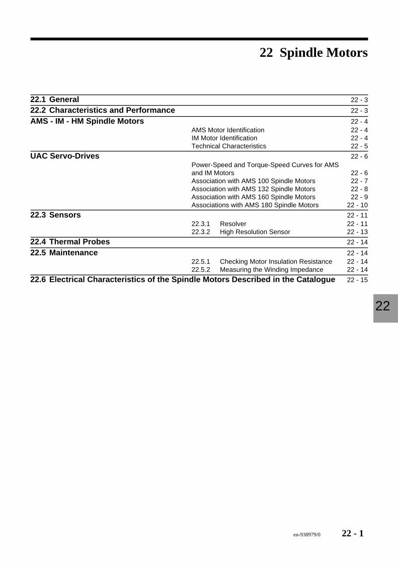
en-938979/0 22 - 1
Spindle Motors
22
22 Spindle Motors
22.1 General 22 - 3
22.2 Characteristics and Performance 22 - 3
AMS - IM - HM Spindle Motors 22 - 4AMS Motor Identification 22 - 4IM Motor Identification 22 - 4Technical Characteristics 22 - 5
UAC Servo-Drives 22 - 6Power-Speed and Torque-Speed Curves for AMSand IM Motors 22 - 6Association with AMS 100 Spindle Motors 22 - 7Association with AMS 132 Spindle Motors 22 - 8Association with AMS 160 Spindle Motors 22 - 9Associations with AMS 180 Spindle Motors 22 - 10
22.3 Sensors 22 - 1122.3.1 Resolver 22 - 1122.3.2 High Resolution Sensor 22 - 13
22.4 Thermal Probes 22 - 14
22.5 Maintenance 22 - 1422.5.1 Checking Motor Insulation Resistance 22 - 1422.5.2 Measuring the Winding Impedance 22 - 14
22.6 Electrical Characteristics of the Spindle Motors Described in the Catalogue 22 - 15

22 - 2 en-938979/0
en-938979/0 22 - 3
Spindle Motors
22
22.1 GeneralThe spindle motors of the NUM DRIVE line are induction motors.
They are asynchronous squirrel cage motors equipped with a speed measurement sensor to control motor slip veryaccurately.
Several lines of motors are available:- Series IM and HM spindle motors- Series AMS spindle motors (this more recent line of motors is gradually replacing the IM line)- AM132 liquid-cooled spindle motors- MotorSpindle motor-driven spindles
This motor technology achieves optimum spindle motor integration in the machine and simplifies the mechanicalparts to the utmost.- Hollow rotor- Liquid-cooled stator- High-resolution sensor + cog wheel.
These motors are used in conjunction with UAC and MDLS flux vector control and sinusoidal control servo-drives.
22.2 Characteristics and PerformanceThe detailed mechanical characteristics of the spindle motors (overall dimensions, shaft loads) are given in NUMDRIVE Catalogue en-938919/3, Chapter 2.
For interfacing the motors and associated servo-drives, refer to the installation and maintenance manuals for theservo-drives:
UAC Manual 738F003/C
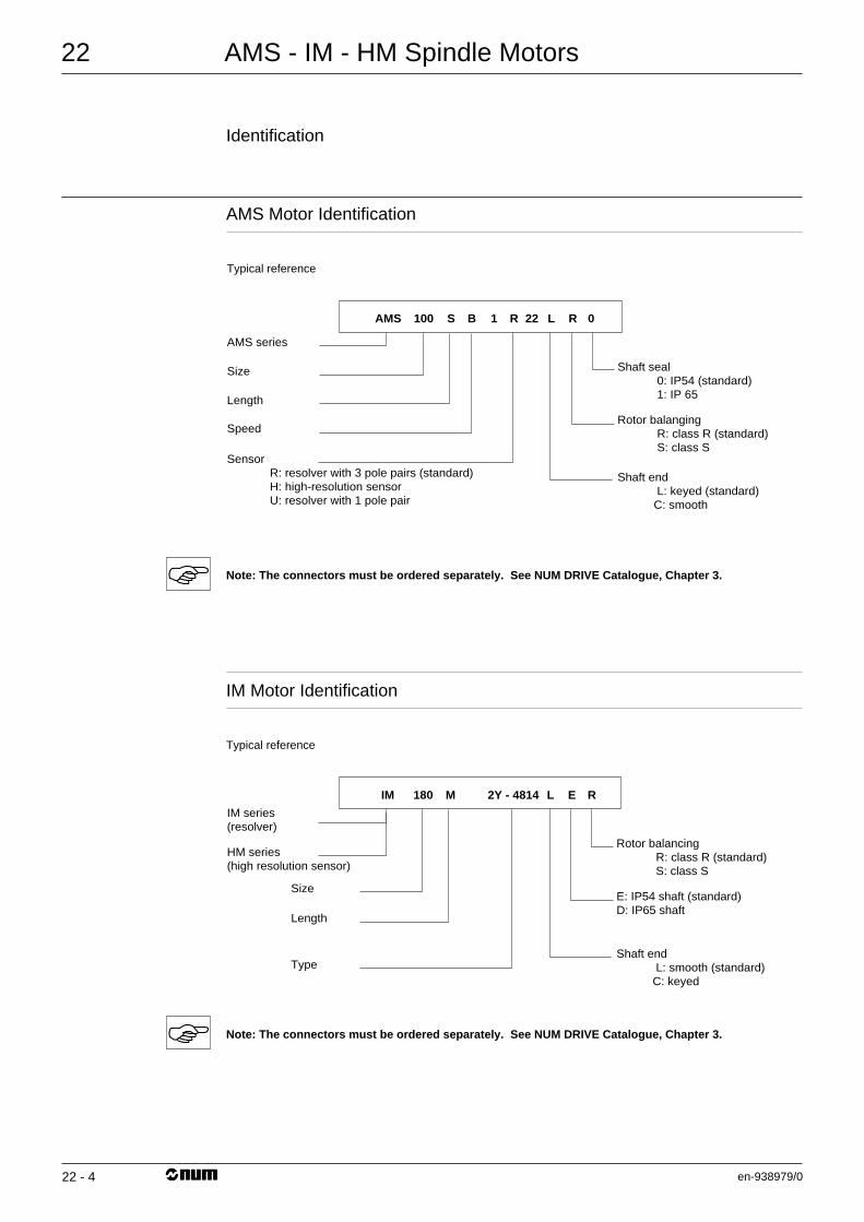
AMS - IM - HM Spindle Motors
en-938979/0
22
22 - 4
Identification
AMS Motor Identification
Typical reference
Shaft seal 0: IP54 (standard) 1: IP 65
AMS series
Size
Length
Speed
Sensor R: resolver with 3 pole pairs (standard) H: high-resolution sensor U: resolver with 1 pole pair
Rotor balanging R: class R (standard) S: class S
Shaft end L: keyed (standard) C: smooth
0 RLR 221BS100AMS
Note: The connectors must be ordered separately. See NUM DRIVE Catalogue, Chapter 3.
IM Motor Identification
Typical reference
Rotor balancing R: class R (standard) S: class S
IM series (resolver)
HM series(high resolution sensor)
Size
Length
Type
E: IP54 shaft (standard)D: IP65 shaft
Shaft end L: smooth (standard) C: keyed
REL2Y - 4814M180IM
Note: The connectors must be ordered separately. See NUM DRIVE Catalogue, Chapter 3.
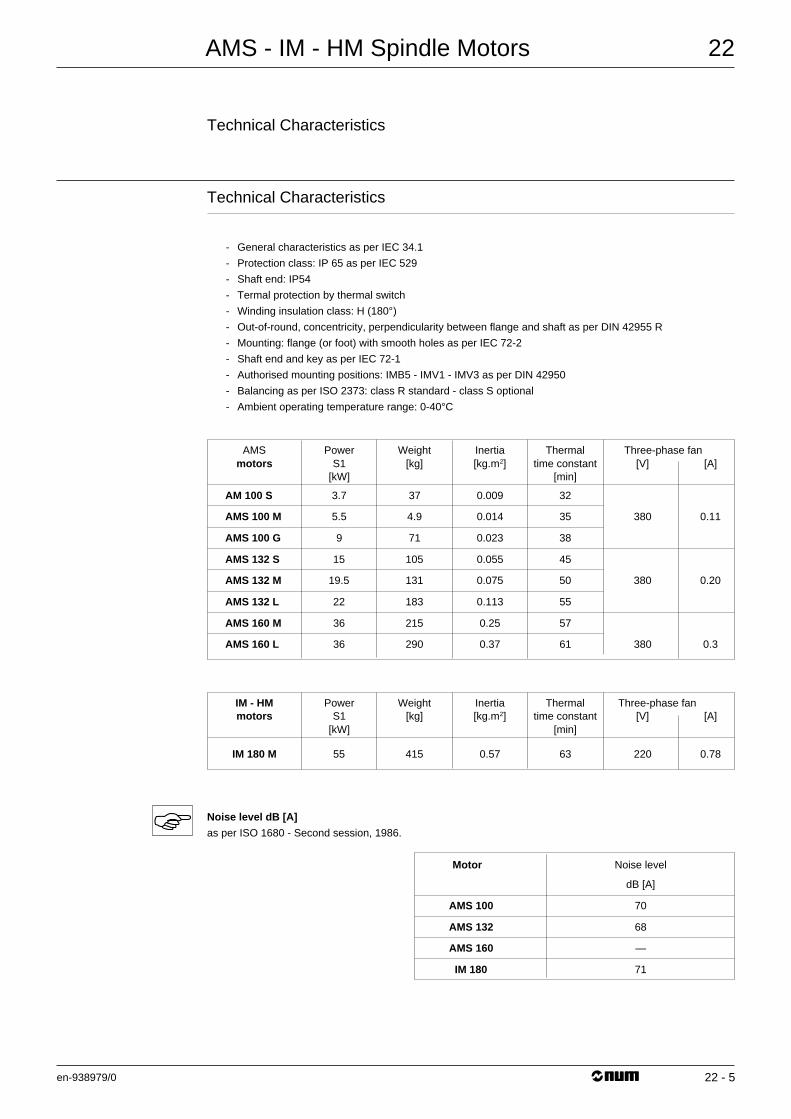
AMS - IM - HM Spindle Motors
en-938979/0
22
22 - 5
Technical Characteristics
Technical Characteristics
- General characteristics as per IEC 34.1
- Protection class: IP 65 as per IEC 529
- Shaft end: IP54
- Termal protection by thermal switch
- Winding insulation class: H (180°)
- Out-of-round, concentricity, perpendicularity between flange and shaft as per DIN 42955 R
- Mounting: flange (or foot) with smooth holes as per IEC 72-2
- Shaft end and key as per IEC 72-1
- Authorised mounting positions: IMB5 - IMV1 - IMV3 as per DIN 42950
- Balancing as per ISO 2373: class R standard - class S optional
- Ambient operating temperature range: 0-40°C
AMS Power Weight Inertia Thermal Three-phase fanmotors S1 [kg] [kg.m2] time constant [V] [A]
[kW] [min]
AM 100 S 3.7 37 0.009 32
AMS 100 M 5.5 4.9 0.014 35 380 0.11
AMS 100 G 9 71 0.023 38
AMS 132 S 15 105 0.055 45
AMS 132 M 19.5 131 0.075 50 380 0.20
AMS 132 L 22 183 0.113 55
AMS 160 M 36 215 0.25 57
AMS 160 L 36 290 0.37 61 380 0.3
IM - HM Power Weight Inertia Thermal Three-phase fanmotors S1 [kg] [kg.m2] time constant [V] [A]
[kW] [min]
IM 180 M 55 415 0.57 63 220 0.78
Noise level dB [A]
as per ISO 1680 - Second session, 1986.
Motor Noise level
dB [A]
AMS 100 70
AMS 132 68
AMS 160 —
IM 180 71
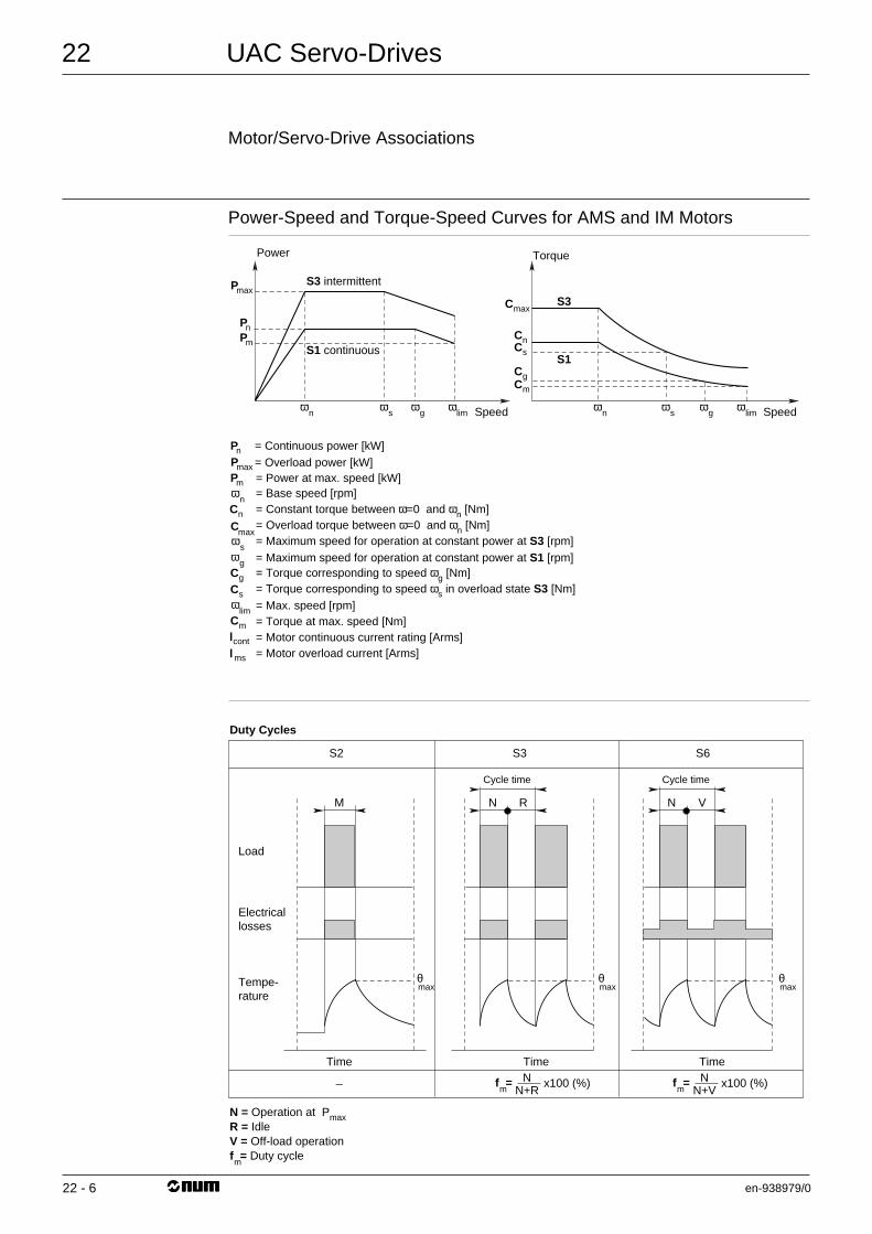
UAC Servo-Drives
en-938979/0
22
22 - 6
Motor/Servo-Drive Associations
Power-Speed and Torque-Speed Curves for AMS and IM Motors
S3 intermittent
S1 continuous
max
ω
Power
Speed
P
n
sω
gω
limω
n
P
mP
Torque
Speedωs
ωg
ω lim
ωn
maxC S3
S1
nCsC
mCgC
= Continuous power [kW]= Overload power [kW]= Power at max. speed [kW]= Base speed [rpm]= Constant torque between ω=0 and ωn [Nm]
= Maximum speed for operation at constant power at S1 [rpm]
= Torque corresponding to speed ωs in overload state S3 [Nm]
= Motor continuous current rating [Arms]= Torque at max. speed [Nm]
= Motor overload current [Arms]
= Torque corresponding to speed ωg [Nm]
= Max. speed [rpm]
= Maximum speed for operation at constant power at S3 [rpm]= Overload torque between ω=0 and ωn [Nm]
maxP
ωs
ωg
cont
ms
ω lim
ωn
nP
mP
maxCnC
sC
mC
gC
ll
Load
Duty Cycles
N = Operation at PmaxR = IdleV = Off-load operationf = Duty cycle
Electricallosses
Tempe-rature
M N R
Time
Cycle time
TimeN
N+Rx100 (%)_
S2 S3 S6
m
f =m
θmax
θmax
θmax
N V
Cycle time
TimeN
N+Vx100 (%)f =
m
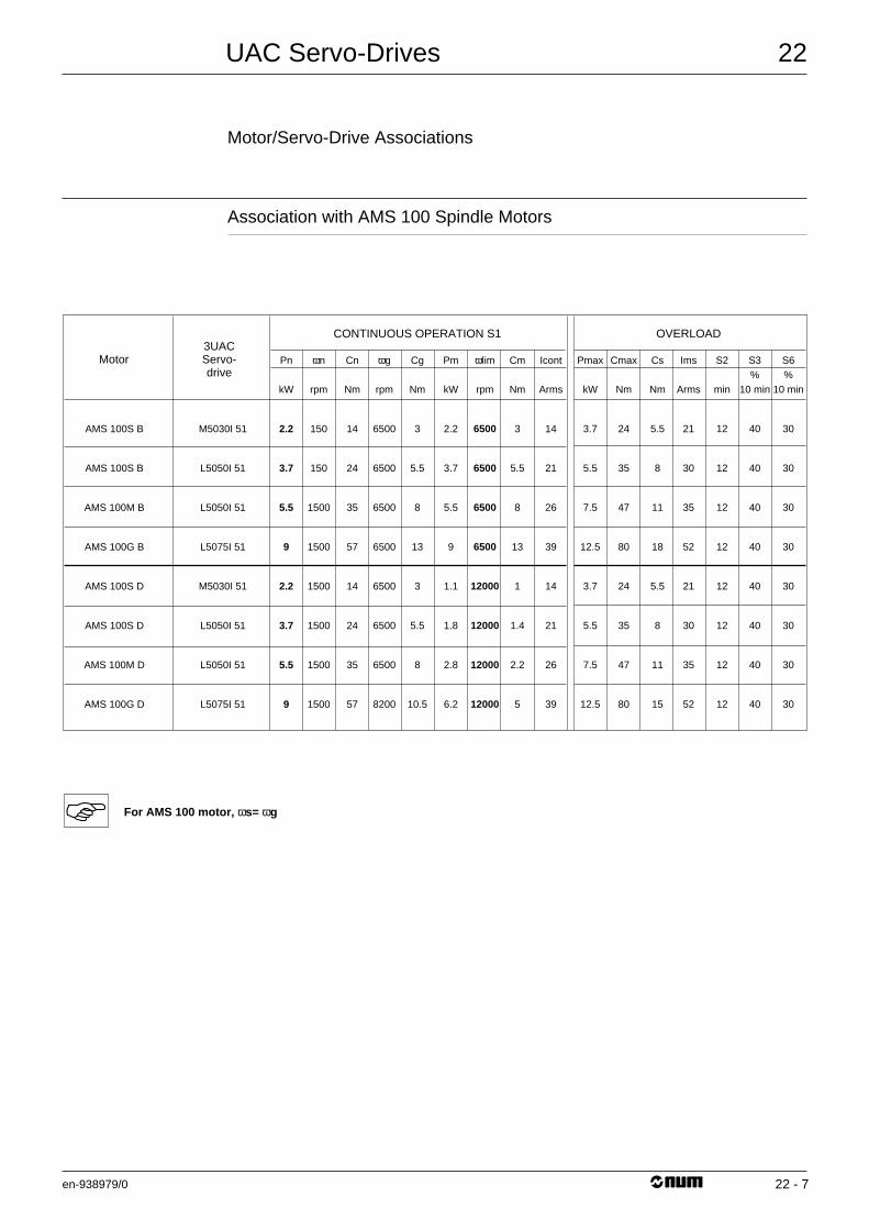
UAC Servo-Drives
en-938979/0
22
22 - 7
Motor/Servo-Drive Associations
Association with AMS 100 Spindle Motors
Motor
CONTINUOUS OPERATION S1 OVERLOAD3UACServo-drive
Pn
kW
2.2
3.7
5.5
9
2.2
3.7
5.5
9
ωn
rpm
150
150
1500
1500
1500
1500
1500
1500
Cn
Nm
14
24
35
57
14
24
35
57
ωg
rpm
6500
6500
6500
6500
6500
6500
6500
8200
Cs
Nm
5.5
8
11
18
5.5
8
11
15
Cg
Nm
3
5.5
8
13
3
5.5
8
10.5
Pm
kW
2.2
3.7
5.5
9
1.1
1.8
2.8
6.2
Cm
Nm
3
5.5
8
13
1
1.4
2.2
5
Icont
Arms
14
21
26
39
14
21
26
39
Pmax
kW
3.7
5.5
7.5
12.5
3.7
5.5
7.5
12.5
Cmax
Nm
24
35
47
80
24
35
47
80
Ims
Arms
21
30
35
52
21
30
35
52
S2
min
12
12
12
12
12
12
12
12
S3%
10 min
40
40
40
40
40
40
40
40
S6%
10 min
30
30
30
30
30
30
30
30
ωlim
rpm
6500
6500
6500
6500
12000
12000
12000
12000
AMS 100S B
AMS 100S B
AMS 100M B
AMS 100G B
AMS 100S D
AMS 100S D
AMS 100M D
AMS 100G D
M5030I 51
L5050I 51
L5050I 51
L5075I 51
M5030I 51
L5050I 51
L5050I 51
L5075I 51
For AMS 100 motor, ωs= ωg
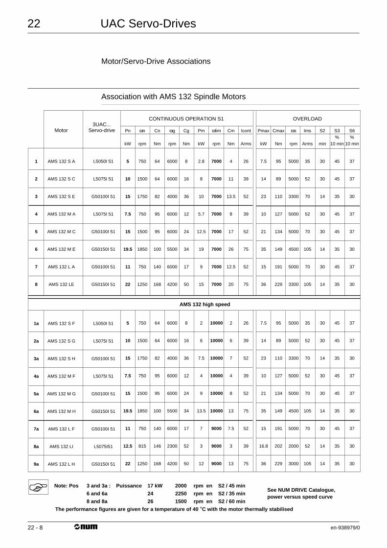
UAC Servo-Drives
en-938979/0
22
22 - 8
Motor/Servo-Drive Associations
Association with AMS 132 Spindle Motors
Motor
CONTINUOUS OPERATION S1
AMS 132 high speed
OVERLOAD3UAC...
Servo-drive Pn
kW
5
10
15
7.5
15
19.5
11
22
ωn
rpm
750
1500
1750
750
1500
1850
750
1250
Cn
Nm
64
64
82
95
95
100
140
168
ωg
rpm
6000
6000
4000
6000
6000
5500
6000
4200
ωs
rpm
5000
5000
3300
5000
5000
4500
5000
3300
Cg
Nm
8
16
36
12
24
34
17
50
Pm
kW
2.8
8
10
5.7
12.5
19
9
15
Cm
Nm
4
11
13.5
8
17
26
12.5
20
Icont
Arms
26
39
52
39
52
75
52
75
Pmax
kW
7.5
14
23
10
21
35
15
36
Cmax
Nm
95
89
110
127
134
149
191
229
Ims
Arms
35
52
70
52
70
105
70
105
S2
min
30
30
14
30
30
14
30
14
S3%
10 min
45
45
35
45
45
35
45
35
S6%
10 min
37
37
30
37
37
30
37
30
ωlim
rpm
7000
7000
7000
7000
7000
7000
7000
7000
AMS 132 S A
AMS 132 S C
AMS 132 S E
AMS 132 M A
AMS 132 M C
AMS 132 M E
AMS 132 L A
AMS 132 LE
1
2
3
4
5
6
7
8
L5050I 51
L5075I 51
G50100I 51
L5075I 51
G50100I 51
G50150I 51
G50100I 51
G50150I 51
5
10
15
7.5
15
19.5
11
12.5
22
750
1500
1750
750
1500
1850
750
815
1250
64
64
82
95
95
100
140
146
168
6000
6000
4000
6000
6000
5500
6000
2300
4200
5000
5000
3300
5000
5000
4500
5000
2000
3000
8
16
36
12
24
34
17
52
50
2
6
7.5
4
9
13.5
7
3
12
2
6
7
4
8
13
7.5
3
13
26
39
52
39
52
75
52
39
75
7.5
14
23
10
21
35
15
16.8
36
95
89
110
127
134
149
191
202
229
35
52
70
52
70
105
70
52
105
30
30
14
30
30
14
30
14
14
45
45
35
45
45
35
45
35
35
37
37
30
37
37
30
37
30
30
10000
10000
10000
10000
10000
10000
9000
9000
9000
AMS 132 S F
AMS 132 S G
AMS 132 S H
AMS 132 M F
AMS 132 M G
AMS 132 M H
AMS 132 L F
AMS 132 LI
AMS 132 L H
1a
2a
3a
4a
5a
6a
7a
8a
9a
L5050I 51
L5075I 51
G50100I 51
L5075I 51
G50100I 51
G50150I 51
G50100I 51
L5075I51
G50150I 51
Note: Pos 3 and 3a : Puissance 17 kW 2000 rpm en S2 / 45 min
6 and 6a 24 2250 rpm en S2 / 35 minSee NUM DRIVE Catalogue,
8 and 8a 26 1500 rpm en S2 / 60 minpower versus speed curve
The performance figures are given for a temperature of 40 °C with the motor thermally stabilised
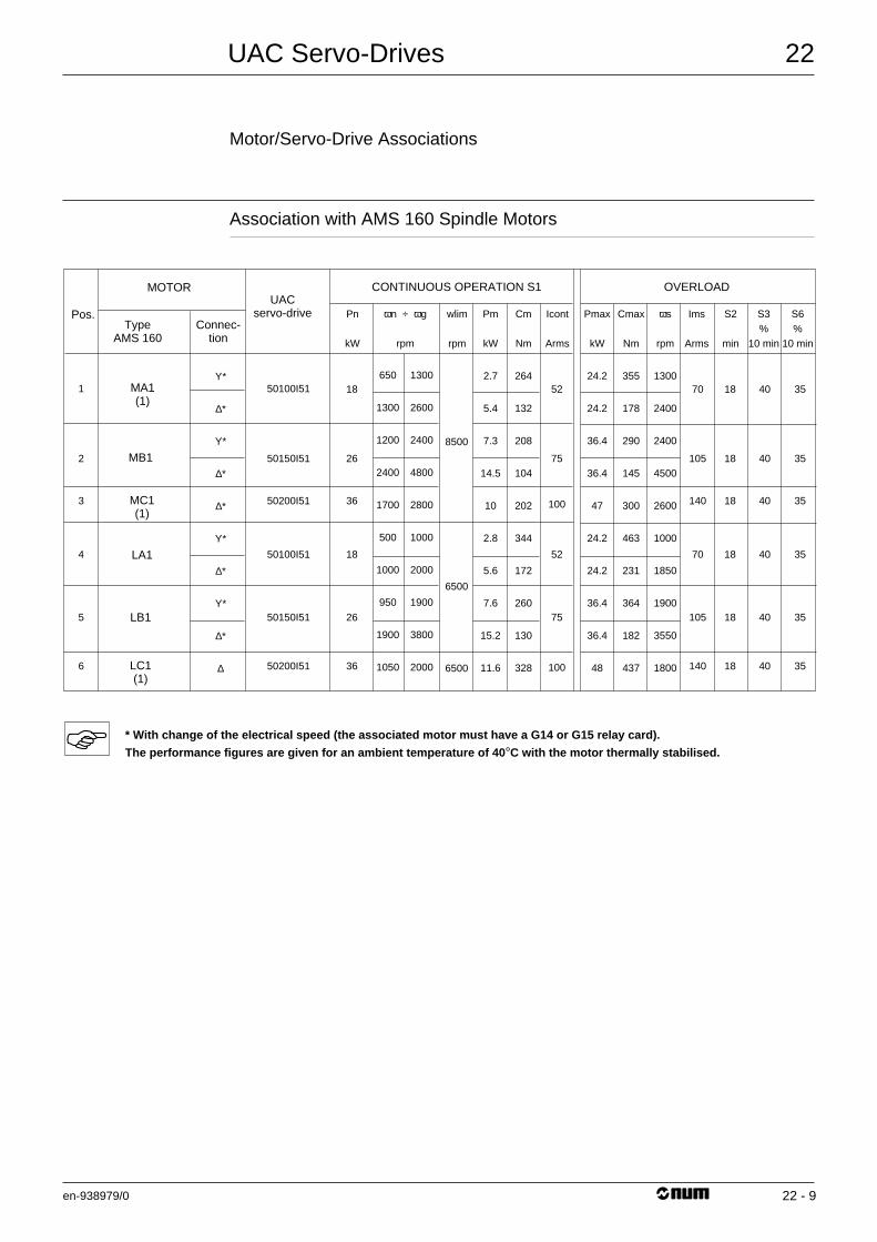
UAC Servo-Drives
en-938979/0
22
22 - 9
Motor/Servo-Drive Associations
Association with AMS 160 Spindle Motors
MOTOR
TypeAMS 160
MA1(1)
MB1
MC1(1)
LA1
LB1
LC1(1)
Connec-tion
CONTINUOUS OPERATION S1 OVERLOADUAC
servo-drivePos. Pn
kW
650
1300
1200
2400
1700
500
1000
950
1900
1050
1300
2600
2400
4800
2800
1000
2000
1900
3800
2000
ωs
rpm
1300
2400
2400
4500
2600
1000
1850
1900
3550
1800
Pm
kW
2.7
5.4
7.3
14.5
10
2.8
5.6
7.6
15.2
11.6
Cm
Nm
264
132
208
104
202
344
172
260
130
328
Icont
Arms
Pmax
kW
24.2
24.2
36.4
36.4
47
24.2
24.2
36.4
36.4
48
Cmax
Nm
355
178
290
145
300
463
231
364
182
437
Ims
Arms
S2
min
S3%
10 min
S6%
10 min
wlim
rpm
1
2
3
4
5
6
Υ*
∆*
Υ*
∆*
∆*
Υ*
∆*
Υ*
∆*
∆
50100I51
50150I51
50200I51
50100I51
50150I51
50200I51
6500
8500
6500
26
18
36
18
26
36
75
52
100
52
75
100
18
18
18
18
18
18
105
70
140
70
105
140
40
40
40
40
40
40
35
35
35
35
35
35
ωn ÷ ωg
rpm
* With change of the electrical speed (the associated motor must have a G14 or G15 relay card).
The performance figures are given for an ambient temperature of 40 °C with the motor thermally stabilised.
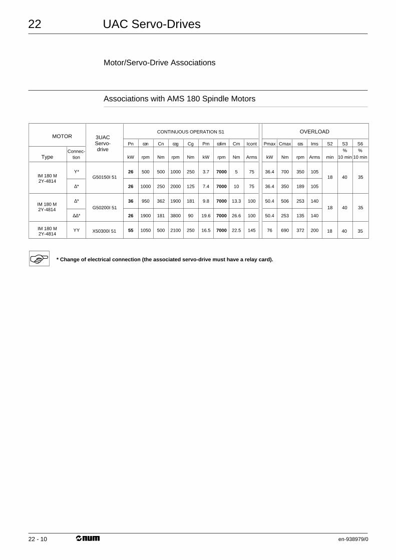
UAC Servo-Drives
en-938979/0
22
22 - 10
Motor/Servo-Drive Associations
Associations with AMS 180 Spindle Motors
MOTOR
TypeConnec-
tion
CONTINUOUS OPERATION S1 OVERLOAD3UACServo-drive
Pn
kW
26
26
36
26
55
ωn
rpm
500
1000
950
1900
1050
Cn
Nm
500
250
362
181
500
ωg
rpm
1000
2000
1900
3800
2100
ωs
rpm
350
189
253
135
372
Cg
Nm
250
125
181
90
250
Pm
kW
3.7
7.4
9.8
19.6
16.5
Cm
Nm
5
10
13.3
26.6
22.5
Icont
Arms
75
75
100
100
145
Pmax
kW
36.4
36.4
50.4
50.4
76
Cmax
Nm
700
350
506
253
690
Ims
Arms
105
105
140
140
200
S2
min
S3%
10 min
S6%
10 min
ωlim
rpm
7000
7000
7000
7000
7000
IM 180 M2Y-4814
IM 180 M2Y-4814
IM 180 M2Y-4814
Υ*
∆*
∆*
∆∆*
ΥΥ
G50150I 51
G50200I 51
X50300I 51
18
18
18
40
40
40
35
35
35
* Change of electrical connection (the associated servo-drive must have a relay card).
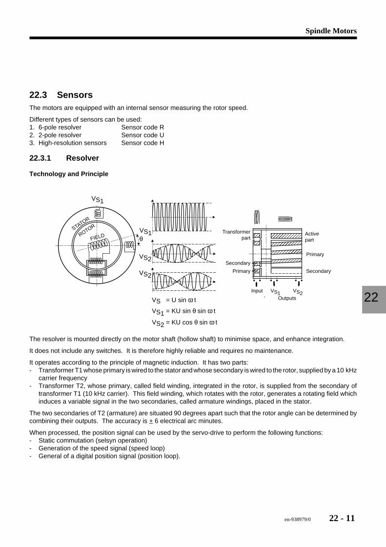
en-938979/0 22 - 11
Spindle Motors
22
22.3 SensorsThe motors are equipped with an internal sensor measuring the rotor speed.
Different types of sensors can be used:1. 6-pole resolver Sensor code R2. 2-pole resolver Sensor code U3. High-resolution sensors Sensor code H
22.3.1 Resolver
Technology and Principle
yyyyyzzzzz yyyyyyzzzzz||||||||||||yyyyyyyyyyzzzzzzzzz|||||||||yyyyyyyyyyyyyzzzzzzzzzzzz||||||yyyyyyyyyyyyyyzzzzzzzzzzzzzzyyyyyzzzzz yyyyzzzzyyyyyzzzzzVS1
VS1
VS2VS = U sin ω t
VS1 = KU sin θ sin ω t
VS2 = KU cos θ sin ω t
VS2
VS2
FIELDSTATOR
ROTOR
θTransformer
part
Secondary
SecondaryPrimary
Primary
Activepart
InputOutputs
VS1
The resolver is mounted directly on the motor shaft (hollow shaft) to minimise space, and enhance integration.
It does not include any switches. It is therefore highly reliable and requires no maintenance.
It operates according to the principle of magnetic induction. It has two parts:- Transformer T1 whose primary is wired to the stator and whose secondary is wired to the rotor, supplied by a 10 kHz
carrier frequency- Transformer T2, whose primary, called field winding, integrated in the rotor, is supplied from the secondary of
transformer T1 (10 kHz carrier). This field winding, which rotates with the rotor, generates a rotating field whichinduces a variable signal in the two secondaries, called armature windings, placed in the stator.
The two secondaries of T2 (armature) are situated 90 degrees apart such that the rotor angle can be determined bycombining their outputs. The accuracy is + 6 electrical arc minutes.
When processed, the position signal can be used by the servo-drive to perform the following functions:- Static commutation (selsyn operation)- Generation of the speed signal (speed loop)- General of a digital position signal (position loop).
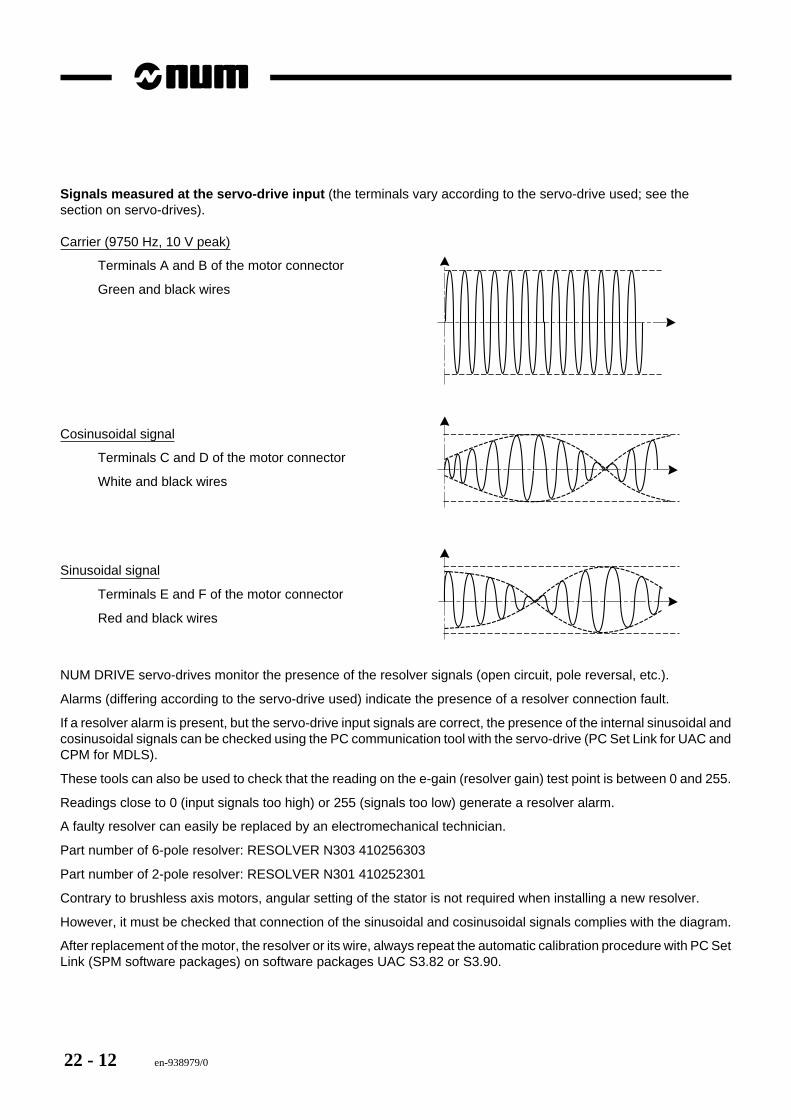
22 - 12 en-938979/0
Signals measured at the servo-drive input (the terminals vary according to the servo-drive used; see thesection on servo-drives).
Carrier (9750 Hz, 10 V peak)
Terminals A and B of the motor connector
Green and black wires
Cosinusoidal signal
Terminals C and D of the motor connector
White and black wires
Sinusoidal signal
Terminals E and F of the motor connector
Red and black wires
NUM DRIVE servo-drives monitor the presence of the resolver signals (open circuit, pole reversal, etc.).
Alarms (differing according to the servo-drive used) indicate the presence of a resolver connection fault.
If a resolver alarm is present, but the servo-drive input signals are correct, the presence of the internal sinusoidal andcosinusoidal signals can be checked using the PC communication tool with the servo-drive (PC Set Link for UAC andCPM for MDLS).
These tools can also be used to check that the reading on the e-gain (resolver gain) test point is between 0 and 255.
Readings close to 0 (input signals too high) or 255 (signals too low) generate a resolver alarm.
A faulty resolver can easily be replaced by an electromechanical technician.
Part number of 6-pole resolver: RESOLVER N303 410256303
Part number of 2-pole resolver: RESOLVER N301 410252301
Contrary to brushless axis motors, angular setting of the stator is not required when installing a new resolver.
However, it must be checked that connection of the sinusoidal and cosinusoidal signals complies with the diagram.
After replacement of the motor, the resolver or its wire, always repeat the automatic calibration procedure with PC SetLink (SPM software packages) on software packages UAC S3.82 or S3.90.
en-938979/0 22 - 13
Spindle Motors
22
22.3.2 High Resolution Sensor
For spindles used for the C axis function, the motors are equipped with a high resolution sensor consisting of a cogwheel (256 or 512 teeth) and a magnetoresistive sensor.
The sensor consists of a magnet and a Wheatstone bridge supplied with +5 V and including two fixed resistors andtwo magnetoresistors. When the cog wheel passes in front of the sensor, the resistance of the magnetoresistorsvaries, generating a sinusoidal waveform across the bridge (256 or 512 sinusoidal cycles per revolution).
The sinusoidal waveform is then divided again by the servo-drive software, which may increase the encoder resolutionup to 1,000,000 pulses per motor revolution at very low speeds.
One of two types of sensors and cog wheels is used, depending on the motor.
AMS and HM motors- Sensor without zero pulse 62AF- Single cog wheel with 256 teeth.
The high resolution sensor signals are processed by a daughterboard located on the servo-drive control card: ACQcard for UAC or EF06B960327 P/N 418960237 for MDLS.
Card part numbers: 2UACCAXIS411, P/N 418401411.
The procedure for checking and adjusting this sensor is described in the UAC Commissioning Manual 738E003/C(pages 75 and 76).
Replacement of a sensor on a motor must always be carried out by a NUM technician.
MS, MSA MotorSpindle- Sensor with zero pulse 63AB- Double cog wheel with 512 teeth
The sensor signals are processed by card 2UACHR411, P/N 418411411 located on the servo-drive control card.
In addition to processing the sensor signals, this card supports an encoder simulation function which providesincremental signals (RS422) used for position measurement by the CNC.- Low resolution output (1024 pulses per revolution) used for spindle measurement- High resolution output (default 65535 pulses per revolution) used for C axis measurement.
The procedure for checking and adjusting this sensor is described in the UAC Commissioning Manual 738E003/C(pages 77-79) or MDLS Commissioning Manual 738013/A (pages 78-80).
Replacement of a sensor on a motor must always be carried out by a NUM technician.
Incorrect adjustment of the motor sensor signals can trigger alarms RSL fixed (UAC) or 09 (MDLS) if the signals aretoo low or EXP flashing (UAC) or 25 (MDLS) if the signals are too high.
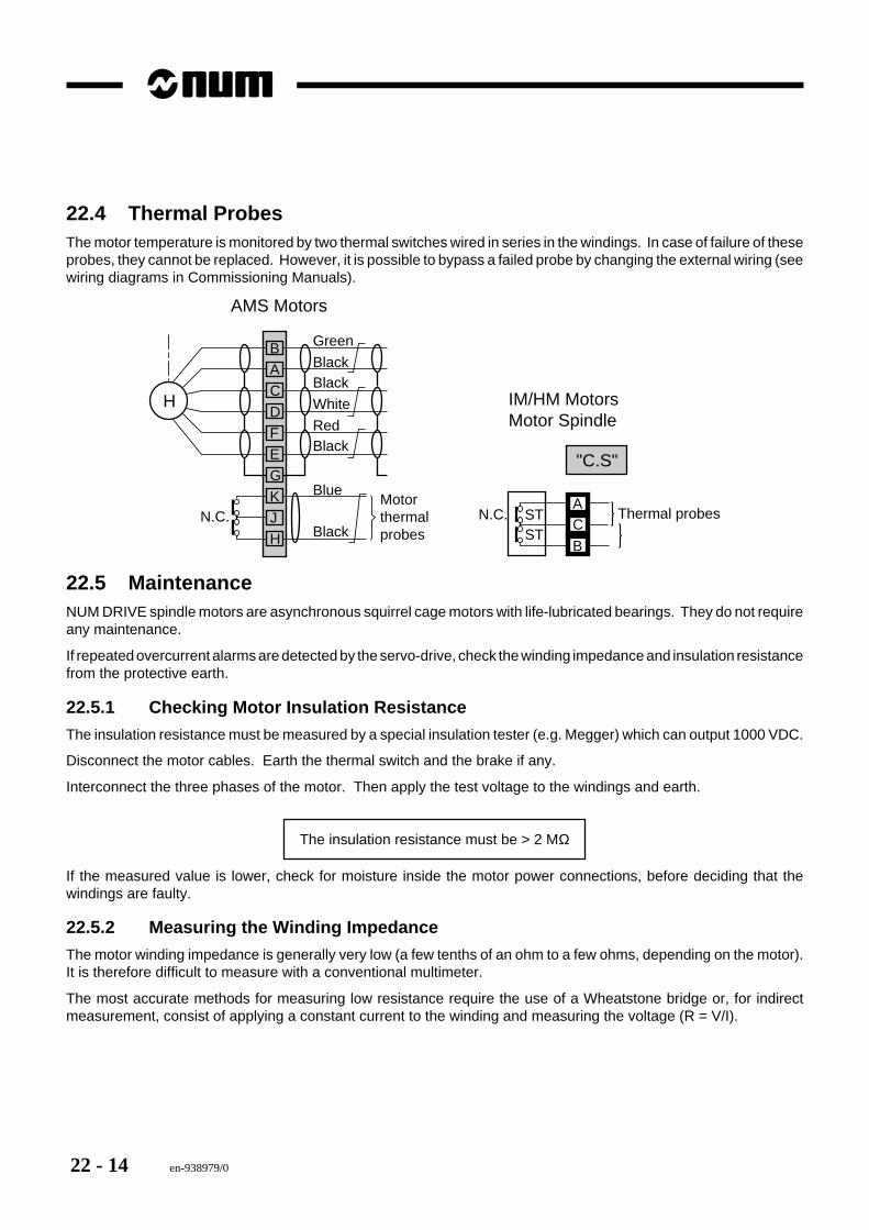
22 - 14 en-938979/0
22.4 Thermal ProbesThe motor temperature is monitored by two thermal switches wired in series in the windings. In case of failure of theseprobes, they cannot be replaced. However, it is possible to bypass a failed probe by changing the external wiring (seewiring diagrams in Commissioning Manuals).
Green
BlackBlack
White
RedBlack
Black
Blue
N.C. N.C. STST
Motorthermalprobes
Thermal probes
H
"C.S"
B
AC
B
A
C
D
F
E
G
K
J
H
AMS Motors
IM/HM MotorsMotor Spindle
22.5 MaintenanceNUM DRIVE spindle motors are asynchronous squirrel cage motors with life-lubricated bearings. They do not requireany maintenance.
If repeated overcurrent alarms are detected by the servo-drive, check the winding impedance and insulation resistancefrom the protective earth.
22.5.1 Checking Motor Insulation Resistance
The insulation resistance must be measured by a special insulation tester (e.g. Megger) which can output 1000 VDC.
Disconnect the motor cables. Earth the thermal switch and the brake if any.
Interconnect the three phases of the motor. Then apply the test voltage to the windings and earth.
The insulation resistance must be > 2 MΩ
If the measured value is lower, check for moisture inside the motor power connections, before deciding that thewindings are faulty.
22.5.2 Measuring the Winding Impedance
The motor winding impedance is generally very low (a few tenths of an ohm to a few ohms, depending on the motor).It is therefore difficult to measure with a conventional multimeter.
The most accurate methods for measuring low resistance require the use of a Wheatstone bridge or, for indirectmeasurement, consist of applying a constant current to the winding and measuring the voltage (R = V/I).
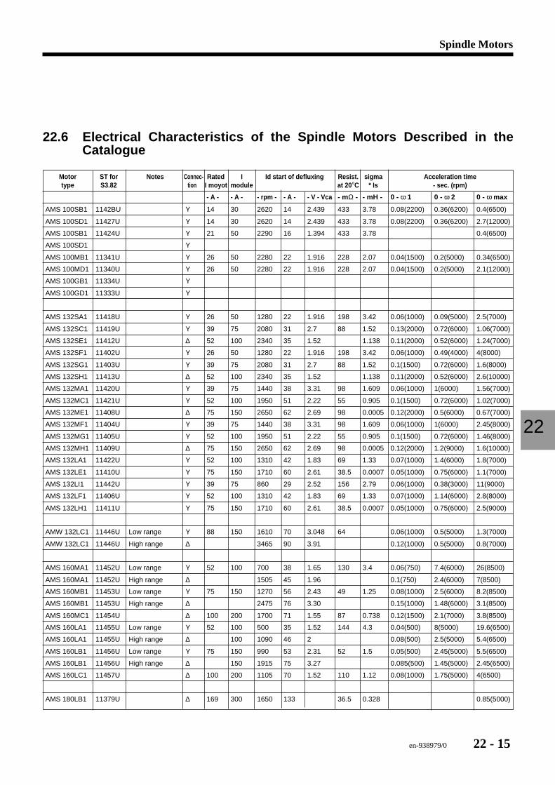
en-938979/0 22 - 15
Spindle Motors
22
22.6 Electrical Characteristics of the Spindle Motors Described in theCatalogue
Motor ST for Notes Connec- Rated I Id start of defluxing Resist. sigma Acceleration timetype S3.82 tion I moyot module at 20 °C * Is - sec. (rpm)
- A - - A - - rpm - - A - - V - Vca - mΩ - - mH - 0 - ω 1 0 - ω 2 0 - ω max
AMS 100SB1 1142BU Y 14 30 2620 14 2.439 433 3.78 0.08(2200) 0.36(6200) 0.4(6500)
AMS 100SD1 11427U Y 14 30 2620 14 2.439 433 3.78 0.08(2200) 0.36(6200) 2.7(12000)
AMS 100SB1 11424U Y 21 50 2290 16 1.394 433 3.78 0.4(6500)
AMS 100SD1 Y
AMS 100MB1 11341U Y 26 50 2280 22 1.916 228 2.07 0.04(1500) 0.2(5000) 0.34(6500)
AMS 100MD1 11340U Y 26 50 2280 22 1.916 228 2.07 0.04(1500) 0.2(5000) 2.1(12000)
AMS 100GB1 11334U Y
AMS 100GD1 11333U Y
AMS 132SA1 11418U Y 26 50 1280 22 1.916 198 3.42 0.06(1000) 0.09(5000) 2.5(7000)
AMS 132SC1 11419U Y 39 75 2080 31 2.7 88 1.52 0.13(2000) 0.72(6000) 1.06(7000)
AMS 132SE1 11412U ∆ 52 100 2340 35 1.52 1.138 0.11(2000) 0.52(6000) 1.24(7000)
AMS 132SF1 11402U Y 26 50 1280 22 1.916 198 3.42 0.06(1000) 0.49(4000) 4(8000)
AMS 132SG1 11403U Y 39 75 2080 31 2.7 88 1.52 0.1(1500) 0.72(6000) 1.6(8000)
AMS 132SH1 11413U ∆ 52 100 2340 35 1.52 1.138 0.11(2000) 0.52(6000) 2.6(10000)
AMS 132MA1 11420U Y 39 75 1440 38 3.31 98 1.609 0.06(1000) 1(6000) 1.56(7000)
AMS 132MC1 11421U Y 52 100 1950 51 2.22 55 0.905 0.1(1500) 0.72(6000) 1.02(7000)
AMS 132ME1 11408U ∆ 75 150 2650 62 2.69 98 0.0005 0.12(2000) 0.5(6000) 0.67(7000)
AMS 132MF1 11404U Y 39 75 1440 38 3.31 98 1.609 0.06(1000) 1(6000) 2.45(8000)
AMS 132MG1 11405U Y 52 100 1950 51 2.22 55 0.905 0.1(1500) 0.72(6000) 1.46(8000)
AMS 132MH1 11409U ∆ 75 150 2650 62 2.69 98 0.0005 0.12(2000) 1.2(9000) 1.6(10000)
AMS 132LA1 11422U Y 52 100 1310 42 1.83 69 1.33 0.07(1000) 1.4(6000) 1.8(7000)
AMS 132LE1 11410U Y 75 150 1710 60 2.61 38.5 0.0007 0.05(1000) 0.75(6000) 1.1(7000)
AMS 132LI1 11442U Y 39 75 860 29 2.52 156 2.79 0.06(1000) 0.38(3000) 11(9000)
AMS 132LF1 11406U Y 52 100 1310 42 1.83 69 1.33 0.07(1000) 1.14(6000) 2.8(8000)
AMS 132LH1 11411U Y 75 150 1710 60 2.61 38.5 0.0007 0.05(1000) 0.75(6000) 2.5(9000)
AMW 132LC1 11446U Low range Y 88 150 1610 70 3.048 64 0.06(1000) 0.5(5000) 1.3(7000)
AMW 132LC1 11446U High range ∆ 3465 90 3.91 0.12(1000) 0.5(5000) 0.8(7000)
AMS 160MA1 11452U Low range Y 52 100 700 38 1.65 130 3.4 0.06(750) 7.4(6000) 26(8500)
AMS 160MA1 11452U High range ∆ 1505 45 1.96 0.1(750) 2.4(6000) 7(8500)
AMS 160MB1 11453U Low range Y 75 150 1270 56 2.43 49 1.25 0.08(1000) 2.5(6000) 8.2(8500)
AMS 160MB1 11453U High range ∆ 2475 76 3.30 0.15(1000) 1.48(6000) 3.1(8500)
AMS 160MC1 11454U ∆ 100 200 1700 71 1.55 87 0.738 0.12(1500) 2.1(7000) 3.8(8500)
AMS 160LA1 11455U Low range Y 52 100 500 35 1.52 144 4.3 0.04(500) 8(5000) 19.6(6500)
AMS 160LA1 11455U High range ∆ 100 1090 46 2 0.08(500) 2.5(5000) 5.4(6500)
AMS 160LB1 11456U Low range Y 75 150 990 53 2.31 52 1.5 0.05(500) 2.45(5000) 5.5(6500)
AMS 160LB1 11456U High range ∆ 150 1915 75 3.27 0.085(500) 1.45(5000) 2.45(6500)
AMS 160LC1 11457U ∆ 100 200 1105 70 1.52 110 1.12 0.08(1000) 1.75(5000) 4(6500)
AMS 180LB1 11379U ∆ 169 300 1650 133 36.5 0.328 0.85(5000)

22 - 16 en-938979/0
en-938979/0 23 - 1
UAC Line
23
23 UAC Line
23.1 General 23 - 3
23.2 Rack 23 - 323.2.1 Rack Identification 23 - 423.2.2 Module Extraction from Rack 23 - 6
23.3 Power Connections 23 - 7

23 - 2 en-938979/0
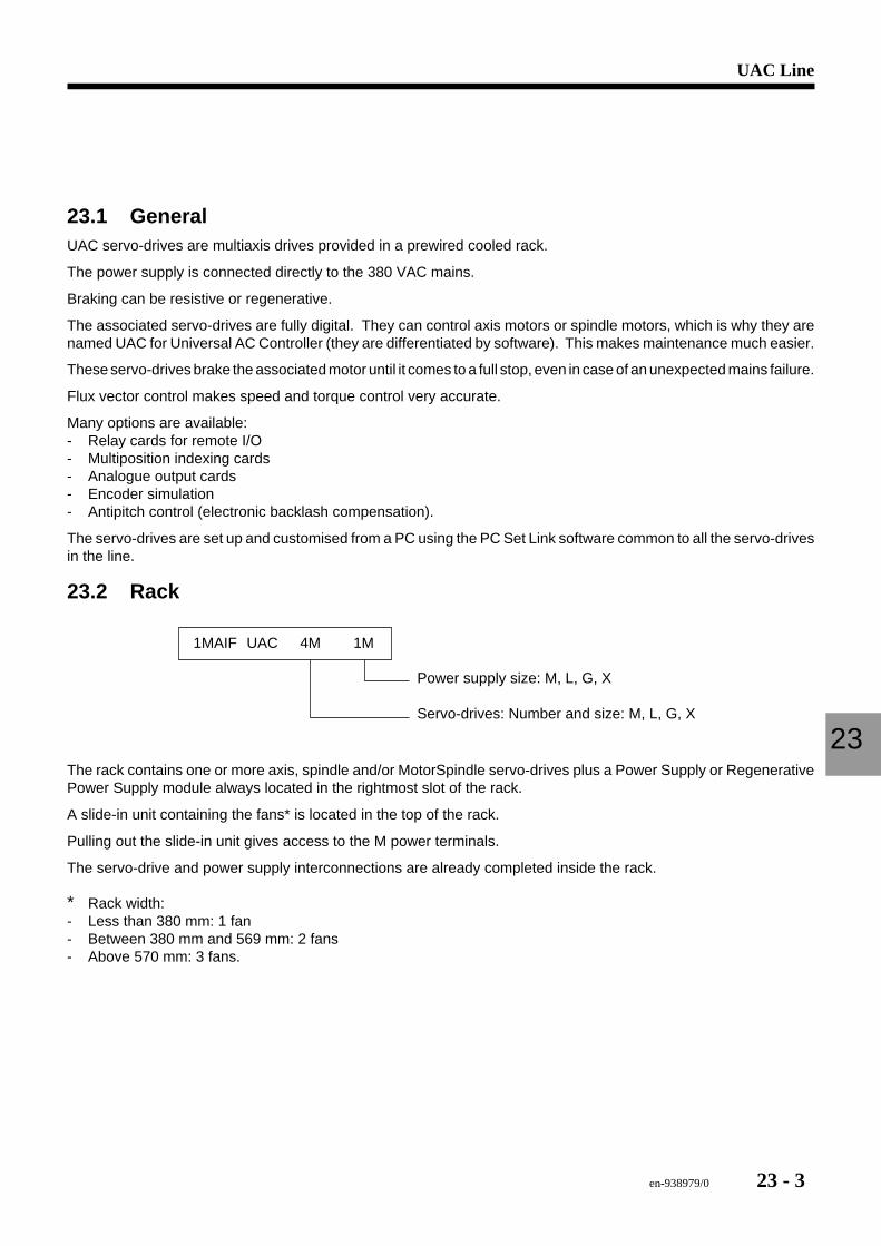
en-938979/0 23 - 3
UAC Line
23
23.1 GeneralUAC servo-drives are multiaxis drives provided in a prewired cooled rack.
The power supply is connected directly to the 380 VAC mains.
Braking can be resistive or regenerative.
The associated servo-drives are fully digital. They can control axis motors or spindle motors, which is why they arenamed UAC for Universal AC Controller (they are differentiated by software). This makes maintenance much easier.
These servo-drives brake the associated motor until it comes to a full stop, even in case of an unexpected mains failure.
Flux vector control makes speed and torque control very accurate.
Many options are available:- Relay cards for remote I/O- Multiposition indexing cards- Analogue output cards- Encoder simulation- Antipitch control (electronic backlash compensation).
The servo-drives are set up and customised from a PC using the PC Set Link software common to all the servo-drivesin the line.
23.2 Rack
Power supply size: M, L, G, X
Servo-drives: Number and size: M, L, G, X
1MAIF UAC 4M 1M
The rack contains one or more axis, spindle and/or MotorSpindle servo-drives plus a Power Supply or RegenerativePower Supply module always located in the rightmost slot of the rack.
A slide-in unit containing the fans* is located in the top of the rack.
Pulling out the slide-in unit gives access to the M power terminals.
The servo-drive and power supply interconnections are already completed inside the rack.
∗ Rack width:- Less than 380 mm: 1 fan- Between 380 mm and 569 mm: 2 fans- Above 570 mm: 3 fans.

23 - 4 en-938979/0
Mounting hole
Fans
Slide-in fan unit
Power terminals
Mountingholes
23.2.1 Rack IdentificationMain rack components
Fan
Screw fastenerto lock the fan unit
Power supply module
Error LEDPower supply module
Rack nameplate
Sliding fastener
Error LED -Servo-drive module
Servo-drive module
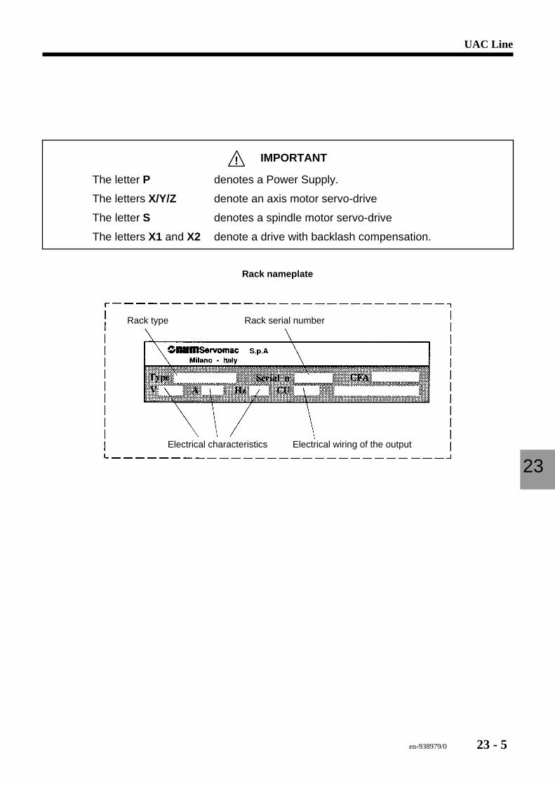
en-938979/0 23 - 5
UAC Line
23
! IMPORTANT
The letter P denotes a Power Supply.
The letters X/Y/Z denote an axis motor servo-drive
The letter S denotes a spindle motor servo-drive
The letters X1 and X2 denote a drive with backlash compensation.
Rack nameplate
Rack serial numberRack type
Electrical characteristics Electrical wiring of the output
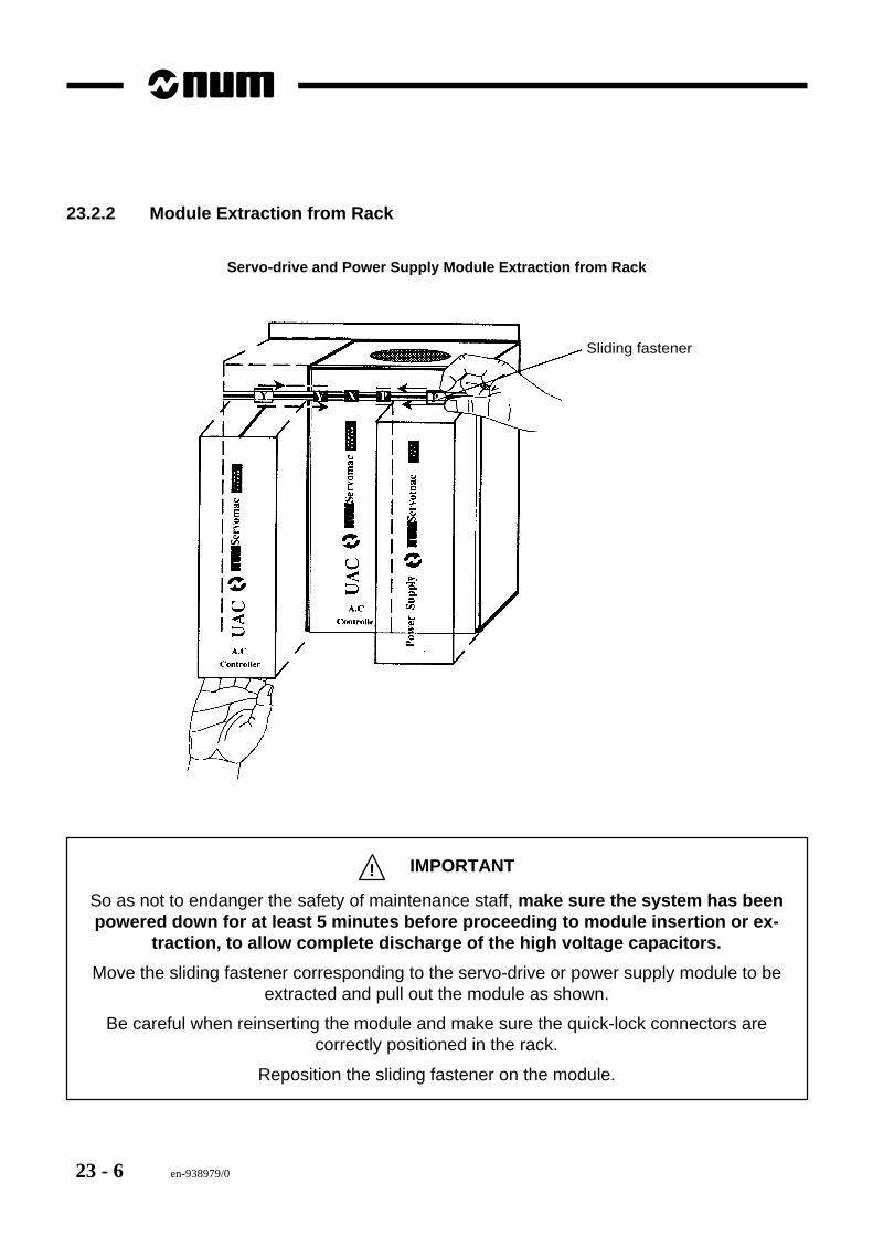
23 - 6 en-938979/0
23.2.2 Module Extraction from Rack
Servo-drive and Power Supply Module Extraction from Rack
Sliding fastener
! IMPORTANT
So as not to endanger the safety of maintenance staff, make sure the system has beenpowered down for at least 5 minutes before proceeding to module insertion or ex-
traction, to allow complete discharge of the high voltage capacitors.
Move the sliding fastener corresponding to the servo-drive or power supply module to beextracted and pull out the module as shown.
Be careful when reinserting the module and make sure the quick-lock connectors arecorrectly positioned in the rack.
Reposition the sliding fastener on the module.

en-938979/0 23 - 7
UAC Line
23
23.3 Power ConnectionsSee UAC Manual 738E003/C:- Chapter 2: pages 21-26 and page 32- Chapter 5: pages 96 et seq.

23 - 8 en-938979/0
en-938979/0 24 - 1
PWS Power Supply Modules
24
24 PWS Power Supply Modules
24.1 Resistive Braking Power Supply Module 24 - 324.1.1 Technical Characteristics 24 - 324.1.1.1 Power Supply Module 24 - 324.1.1.2 Power Supply Modules with External
Braking Resistor 24 - 424.1.1.3 External Braking Resistors - Overall
Dimensions and Mounting 24 - 524.1.2 Maintenance 24 - 624.1.2.1 Alarms 24 - 624.1.2.2 Fuses 24 - 9
24.2 Regenerative Power Supply Module 24 - 1024.2.1 Technical Characteristics 24 - 1024.2.1.1 Regenerative Power Supply Module 24 - 1024.2.2 Configuration 24 - 1124.2.3 Maintenance 24 - 1224.2.3.1 Alarms 24 - 1224.2.3.2 Brownouts 24 - 16

24 - 2 en-938979/0
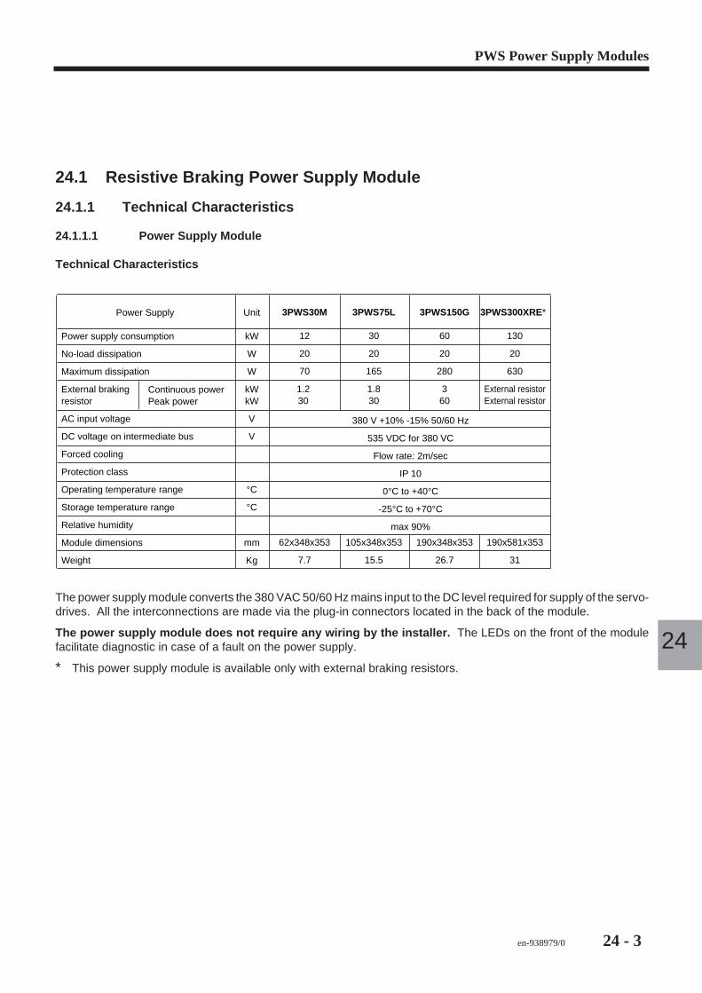
en-938979/0 24 - 3
PWS Power Supply Modules
24
24.1 Resistive Braking Power Supply Module
24.1.1 Technical Characteristics
24.1.1.1 Power Supply Module
Technical Characteristics
Power Supply
Power supply consumption
No-load dissipation
Maximum dissipation
External brakingresistor
AC input voltage
DC voltage on intermediate bus
Forced cooling
Protection class
Operating temperature range
Storage temperature range
Relative humidity
Module dimensions
Weight
Unit
kW
W
W
kWkW
V
V
°C
°C
mm
Kg
Continuous powerPeak power
3PWS150G
60
20
280
360
190x348x353
26.7
3PWS30M
12
20
70
1.2 30
62x348x353
7.7
3PWS300XRE∗
130
20
630
External resistorExternal resistor
190x581x353
31
3PWS75L
30
20
165
1.830
105x348x353
15.5
380 V +10% -15% 50/60 Hz
535 VDC for 380 VC
Flow rate: 2m/sec
IP 10
0°C to +40°C
-25°C to +70°C
max 90%
The power supply module converts the 380 VAC 50/60 Hz mains input to the DC level required for supply of the servo-drives. All the interconnections are made via the plug-in connectors located in the back of the module.
The power supply module does not require any wiring by the installer. The LEDs on the front of the modulefacilitate diagnostic in case of a fault on the power supply.
∗ This power supply module is available only with external braking resistors.
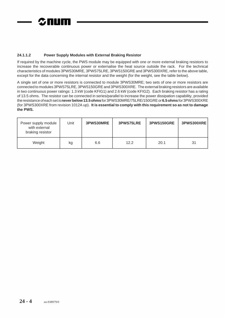
24 - 4 en-938979/0
24.1.1.2 Power Supply Modules with External Braking Resistor
If required by the machine cycle, the PWS module may be equipped with one or more external braking resistors toincrease the recoverable continuous power or externalise the heat source outside the rack. For the technicalcharacteristics of modules 3PWS30MRE, 3PWS75LRE, 3PWS150GRE and 3PWS300XRE, refer to the above table,except for the data concerning the internal resistor and the weight (for the weight, see the table below).
A single set of one or more resistors is connected to module 3PWS30MRE; two sets of one or more resistors areconnected to modules 3PWS75LRE, 3PWS150GRE and 3PWS300XRE. The external braking resistors are availablein two continuous power ratings: 1.3 kW (code KFIG1) and 2.6 kW (code KFIG2). Each braking resistor has a ratingof 13.5 ohms. The resistor can be connected in series/parallel to increase the power dissipation capability, providedthe resistance of each set is never below 13.5 ohms for 3PWS30MRE/75LRE/150GRE or 6.5 ohms for 3PWS300XRE(for 3PWS300XRE from revision 1012A up). It is essential to comply with this requirement so as not to damagethe PWS.
Power supply module Unit 3PWS30MRE 3PWS75LRE 3PWS150GRE 3PWS300XRE with external
braking resistor
Weight kg 6.6 12.2 20.1 31
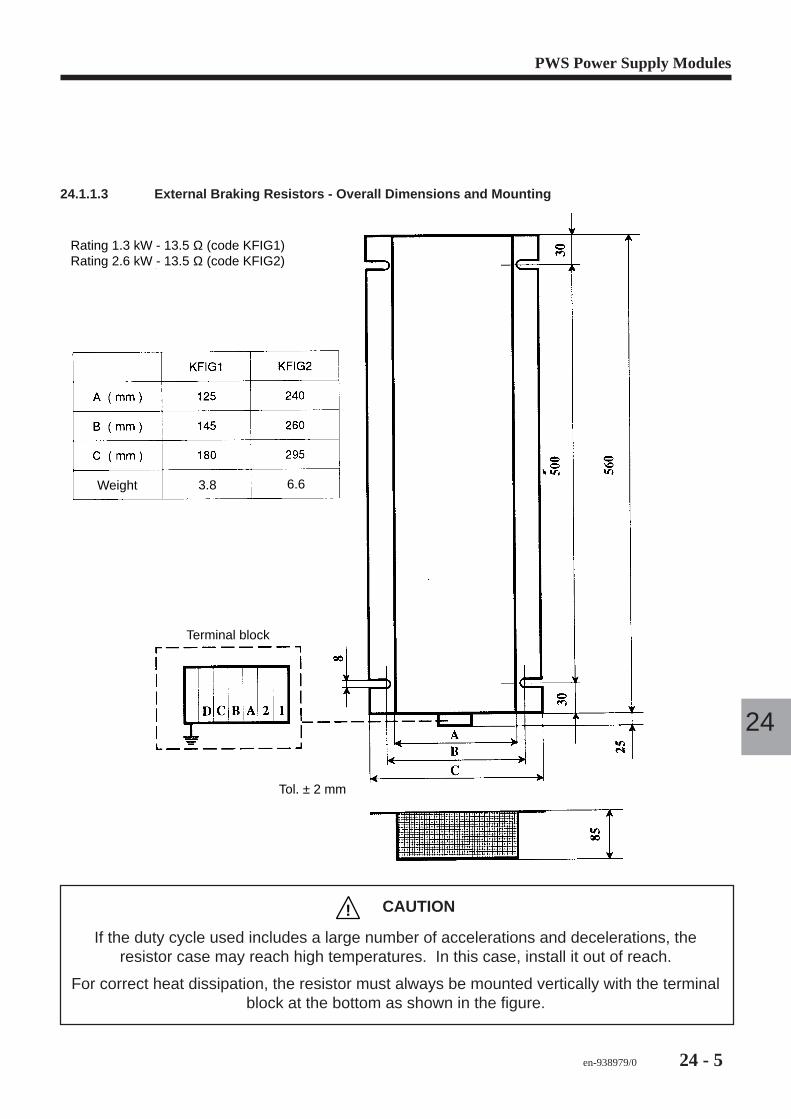
en-938979/0 24 - 5
PWS Power Supply Modules
24
24.1.1.3 External Braking Resistors - Overall Dimensions and Mounting
Rating 1.3 kW - 13.5 Ω (code KFIG1)Rating 2.6 kW - 13.5 Ω (code KFIG2)
Weight 3.8 6.6
Terminal block
Tol. ± 2 mm
! CAUTION
If the duty cycle used includes a large number of accelerations and decelerations, theresistor case may reach high temperatures. In this case, install it out of reach.
For correct heat dissipation, the resistor must always be mounted vertically with the terminalblock at the bottom as shown in the figure.
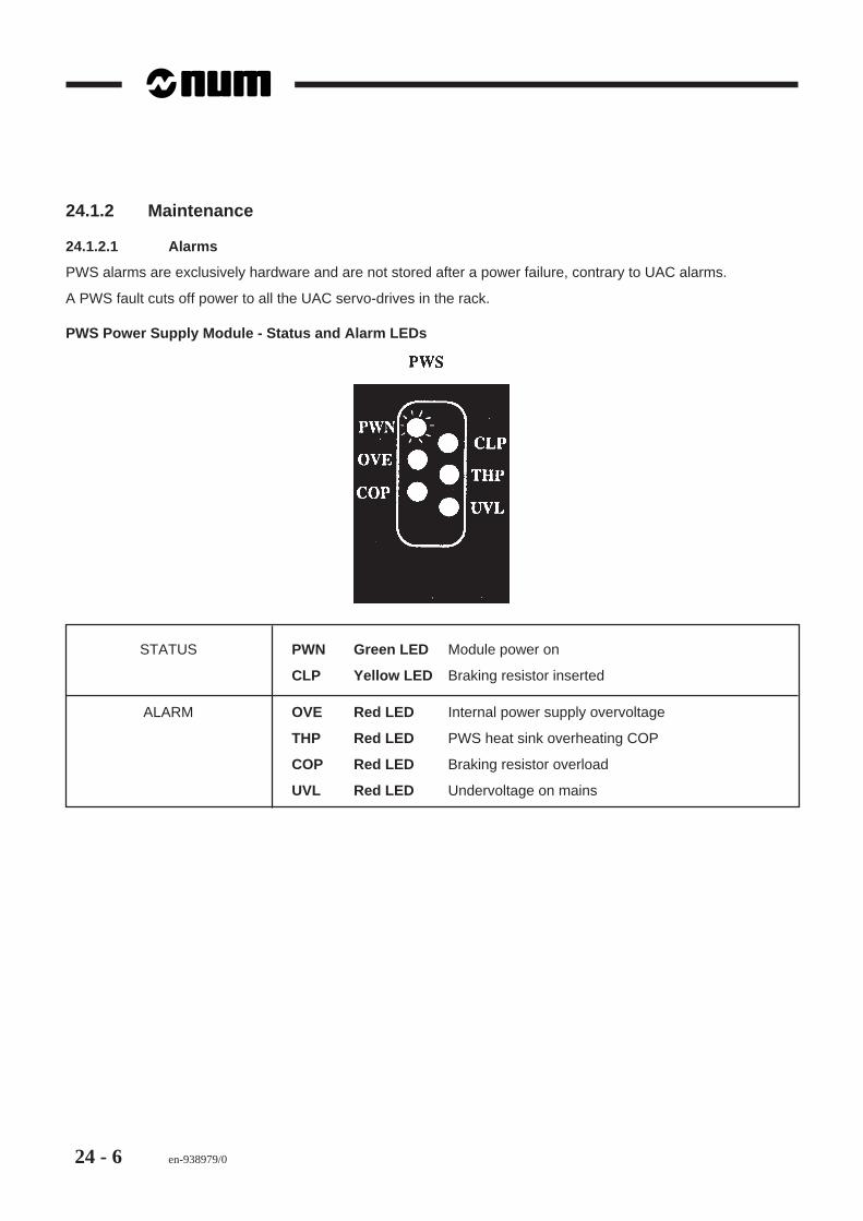
24 - 6 en-938979/0
24.1.2 Maintenance
24.1.2.1 Alarms
PWS alarms are exclusively hardware and are not stored after a power failure, contrary to UAC alarms.
A PWS fault cuts off power to all the UAC servo-drives in the rack.
PWS Power Supply Module - Status and Alarm LEDs
STATUS PWN Green LED Module power on
CLP Yellow LED Braking resistor inserted
ALARM OVE Red LED Internal power supply overvoltage
THP Red LED PWS heat sink overheating COP
COP Red LED Braking resistor overload
UVL Red LED Undervoltage on mains

en-938979/0 24 - 7
PWS Power Supply Modules
24
PWS Power Supply Module - Status LEDs
PWN
CLP
The green PWN LED is lit when the module is powered.
The yellow LED is lit when the motor is being braked and power is being dissipated by the braking resistor.
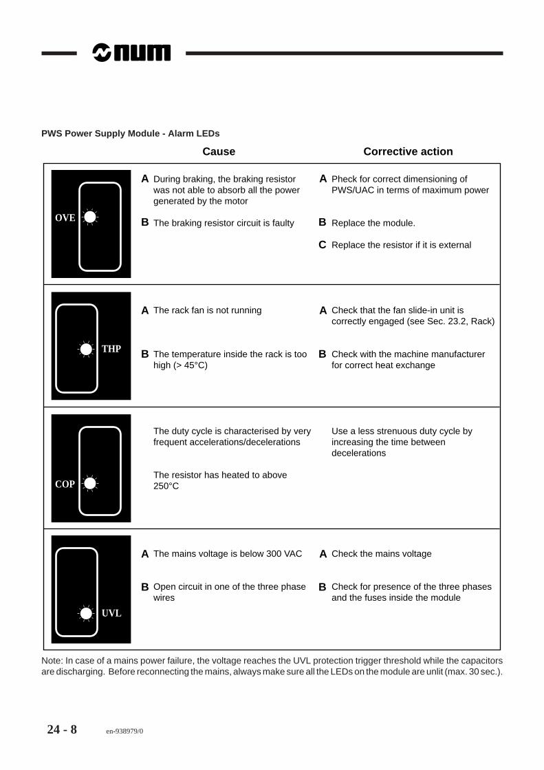
24 - 8 en-938979/0
PWS Power Supply Module - Alarm LEDs
OVE
COP
THP
UVL
During braking, the braking resistor was not able to absorb all the power generated by the motor
The braking resistor circuit is faulty
Pheck for correct dimensioning of PWS/UAC in terms of maximum power
Replace the module.
Replace the resistor if it is external
A
B B
C
A
The rack fan is not running
The temperature inside the rack is too high (> 45°C)
Check that the fan slide-in unit is correctly engaged (see Sec. 23.2, Rack)
Check with the machine manufacturer for correct heat exchange
The duty cycle is characterised by very frequent accelerations/decelerations
The resistor has heated to above 250°C
Use a less strenuous duty cycle by increasing the time between decelerations
A
B B
A
The mains voltage is below 300 VAC
Open circuit in one of the three phase wires
Check the mains voltage
Check for presence of the three phases and the fuses inside the module
A
B B
A
Cause Corrective action
Note: In case of a mains power failure, the voltage reaches the UVL protection trigger threshold while the capacitorsare discharging. Before reconnecting the mains, always make sure all the LEDs on the module are unlit (max. 30 sec.).
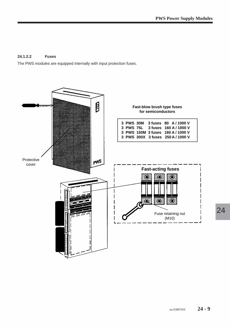
en-938979/0 24 - 9
PWS Power Supply Modules
24
24.1.2.2 Fuses
The PWS modules are equipped internally with input protection fuses.
Fast-blow brush type fusesfor semiconductors
3 PWS 30M 3 fuses 80 A / 1000 V3 PWS 75L 3 fuses 160 A / 1000 V3 PWS 150M 3 fuses 160 A / 1000 V3 PWS 300X 3 fuses 250 A / 1000 V
Protectivecover
Fuse retaining nut (M10)
Fast-acting fuses
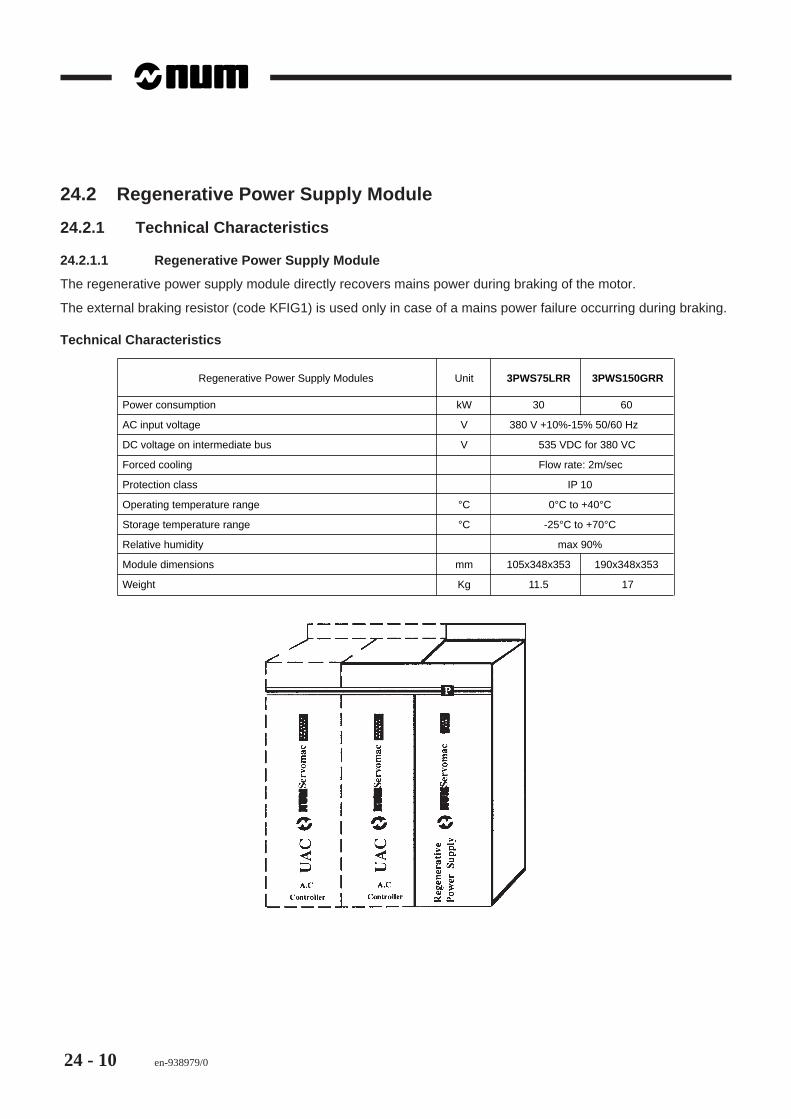
24 - 10 en-938979/0
24.2 Regenerative Power Supply Module
24.2.1 Technical Characteristics
24.2.1.1 Regenerative Power Supply Module
The regenerative power supply module directly recovers mains power during braking of the motor.
The external braking resistor (code KFIG1) is used only in case of a mains power failure occurring during braking.
Technical Characteristics
Regenerative Power Supply Modules Unit 3PWS75LRR 3PWS150GRR
Power consumption kW 30 60
AC input voltage V 380 V +10%-15% 50/60 Hz
DC voltage on intermediate bus V 535 VDC for 380 VC
Forced cooling Flow rate: 2m/sec
Protection class IP 10
Operating temperature range °C 0°C to +40°C
Storage temperature range °C -25°C to +70°C
Relative humidity max 90%
Module dimensions mm 105x348x353 190x348x353
Weight Kg 11.5 17
en-938979/0 24 - 11
PWS Power Supply Modules
24
24.2.2 Configuration
The regenerative power supply is mounted in a UAC rack.
Racks with PWS75
The rack is the same regardless of whether a normal or a regenerative power supply is used (see UAC installationmanual, pages 23 and 25).
Racks with PWS150
Different rack types are used for normal and regenerative power supplies.
The regenerative power supply must always be used with the following external components:- A three-phase choke coil (RL75 or RL150) applying an inductive load to the power supply and limiting the AC ripple
current- A capacitive filter HPPM166 (3x16.6 µF, 440 V) decreasing the noise generated by the power supply- An external braking resistor KFIG1 (13.5 ohms, 1300 W), not used during normal operation but providing the
following functions:. A soft start of the power supply by limiting the load in the wires at start-up. Braking in case of a mains power failure
- Fuses: unlike the normal power supply, the fuses are not integrated and must be installed by the customer.
Fuses to be used (see Marketing Note of 22 June 1993):- 3PWS75LRR: Brush 63 AFE or equivalent Protistors
Nominal voltage = 660 Vrms, I2t at 660 Vrms = 700 A2.s in 3 ms- 3PWS150GRR: Brush 140 AFE or equivalent Protistors
Nominal voltage = 660 Vrms, I2t at 660 Vrms = 1500 A2.s in 3 ms
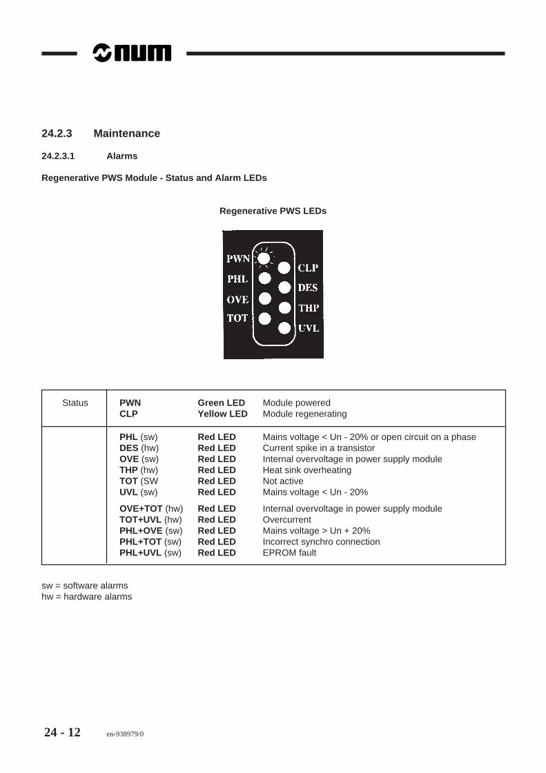
24 - 12 en-938979/0
24.2.3 Maintenance
24.2.3.1 Alarms
Regenerative PWS Module - Status and Alarm LEDs
Regenerative PWS LEDs
Status PWN Green LED Module poweredCLP Yellow LED Module regenerating
PHL (sw) Red LED Mains voltage < Un - 20% or open circuit on a phaseDES (hw) Red LED Current spike in a transistorOVE (sw) Red LED Internal overvoltage in power supply moduleTHP (hw) Red LED Heat sink overheatingTOT (SW Red LED Not activeUVL (sw) Red LED Mains voltage < Un - 20%
OVE+TOT (hw) Red LED Internal overvoltage in power supply moduleTOT+UVL (hw) Red LED OvercurrentPHL+OVE (sw) Red LED Mains voltage > Un + 20%PHL+TOT (sw) Red LED Incorrect synchro connectionPHL+UVL (sw) Red LED EPROM fault
sw = software alarmshw = hardware alarms
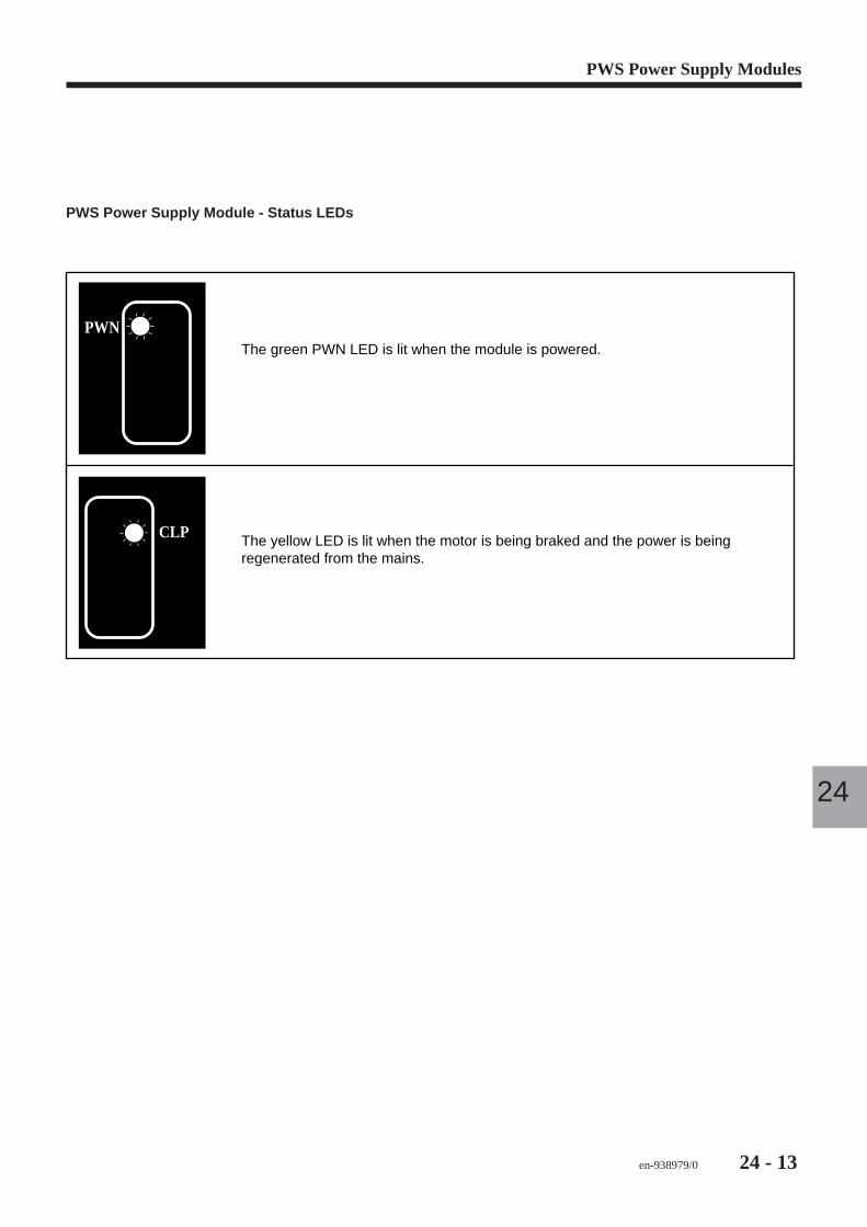
en-938979/0 24 - 13
PWS Power Supply Modules
24
PWS Power Supply Module - Status LEDs
PWN
CLP
The green PWN LED is lit when the module is powered.
The yellow LED is lit when the motor is being braked and the power is being regenerated from the mains.
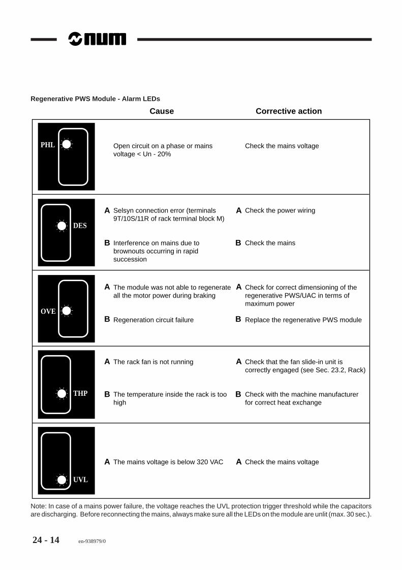
24 - 14 en-938979/0
Regenerative PWS Module - Alarm LEDs
PHL
OVE
DES
THP
UVL
Open circuit on a phase or mains voltage < Un - 20%
Check the mains voltage
Selsyn connection error (terminals 9T/10S/11R of rack terminal block M)
Interference on mains due to brownouts occurring in rapid succession
Check the power wiring
Check the mains
The module was not able to regenerate all the motor power during braking
Regeneration circuit failure
Check for correct dimensioning of the regenerative PWS/UAC in terms of maximum power
Replace the regenerative PWS module
A
B
A
B
B
A
B
A
The rack fan is not running
The temperature inside the rack is too high
Check that the fan slide-in unit is correctly engaged (see Sec. 23.2, Rack)
Check with the machine manufacturer for correct heat exchange
A
B B
A
The mains voltage is below 320 VAC Check the mains voltageA A
Cause Corrective action
Note: In case of a mains power failure, the voltage reaches the UVL protection trigger threshold while the capacitorsare discharging. Before reconnecting the mains, always make sure all the LEDs on the module are unlit (max. 30 sec.).
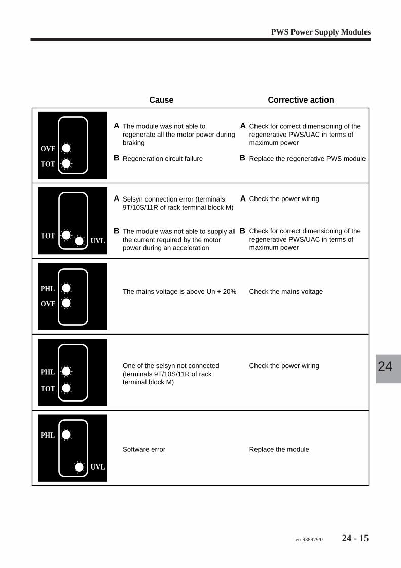
en-938979/0 24 - 15
PWS Power Supply Modules
24
OVE
TOT
PHL
OVE
PHL
TOT
UVL
UVL
The module was not able to regenerate all the motor power during braking
Regeneration circuit failure
Check for correct dimensioning of the regenerative PWS/UAC in terms of maximum power
Replace the regenerative PWS module
Selsyn connection error (terminals 9T/10S/11R of rack terminal block M)
The module was not able to supply all the current required by the motor power during an acceleration
Check the power wiring
Check for correct dimensioning of the regenerative PWS/UAC in terms of maximum power
The mains voltage is above Un + 20% Check the mains voltage
A
B
A
B
B
A
B
A
One of the selsyn not connected (terminals 9T/10S/11R of rack terminal block M)
Check the power wiring
Software error Replace the module
Cause Corrective action
TOT
PHL

24 - 16 en-938979/0
24.2.3.2 Brownouts
The regenerative system is disconnected when brownouts occur on the mains, then reconnected when power isrestored.
If the brownout lasts more than three cycles, the system stops and a fault is indicated.
en-938979/0 25 - 1
UAC Servo-Drives
25
25 UAC Servo-Drives
25.1 Technical Characteristics 25 - 3
25.2 Hardware Implementation 25 - 425.2.1 ACQ Card 25 - 525.2.1.1 Replacing the RAM 25 - 725.2.1.2 Different Types of ACQ Cards 25 - 725.2.1.3 Compatibility of ACQ Cards with
Software Versions 25 - 825.2.1.4 Connector mb (ACQ card) 25 - 925.2.2 IP1 Card 25 - 1025.2.3 AL1 LED Card 25 - 1025.2.4 Optional Cards 25 - 1025.2.4.1 RS232 Serial Interface Card 25 - 1025.2.4.2 DAC Card (analogue outputs) 25 - 11
25.3 Maintenance - Alarms 25 - 1425.3.1 Clearing Stored Alarms 25 - 1525.3.2 UAC Module - Status LEDs 25 - 1625.3.3 UAC Module - Software Alarm
Indications 25 - 1625.3.4 UAC Module - Hardware Alarm
Indications 25 - 17

25 - 2 en-938979/0
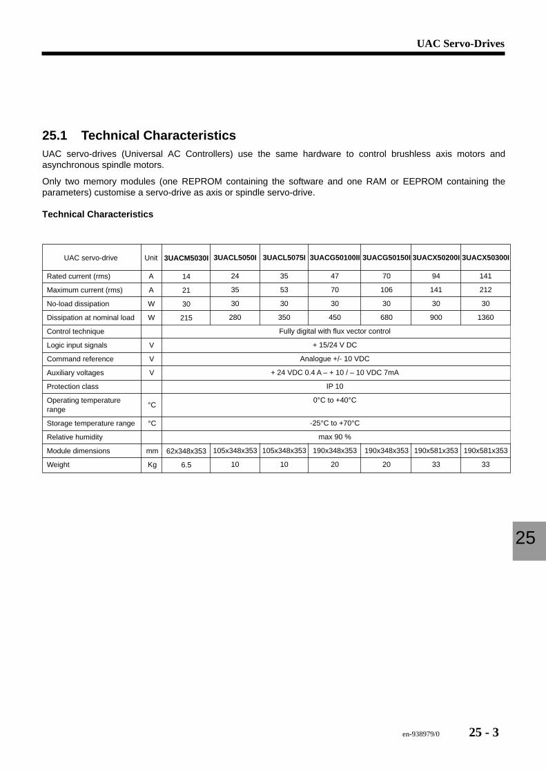
en-938979/0 25 - 3
UAC Servo-Drives
25
25.1 Technical CharacteristicsUAC servo-drives (Universal AC Controllers) use the same hardware to control brushless axis motors andasynchronous spindle motors.
Only two memory modules (one REPROM containing the software and one RAM or EEPROM containing theparameters) customise a servo-drive as axis or spindle servo-drive.
Technical Characteristics
UAC servo-drive
Rated current (rms)
Maximum current (rms)
No-load dissipation
Dissipation at nominal load
Control technique
Logic input signals
Command reference
Auxiliary voltages
Protection class
Operating temperature range
Storage temperature range
Relative humidity
Module dimensions
Weight
Unit
A
A
W
W
V
V
V
°C
°C
mm
Kg
3UACG50100II
47
70
30
450
Fully digital with flux vector control
+ 15/24 V DC
Analogue +/- 10 VDC
+ 24 VDC 0.4 A – + 10 / – 10 VDC 7mA
IP 10
0°C to +40°C
-25°C to +70°C
max 90 %
190x348x353
20
3UACM5030I
14
21
30
215
62x348x353
6.5
3UACL5050I
24
35
30
280
105x348x353
10
3UACL5075I
35
53
30
350
105x348x353
10
3UACG50150I
70
106
30
680
190x348x353
20
3UACX50200I
94
141
30
900
190x581x353
33
3UACX50300I
141
212
30
1360
190x581x353
33
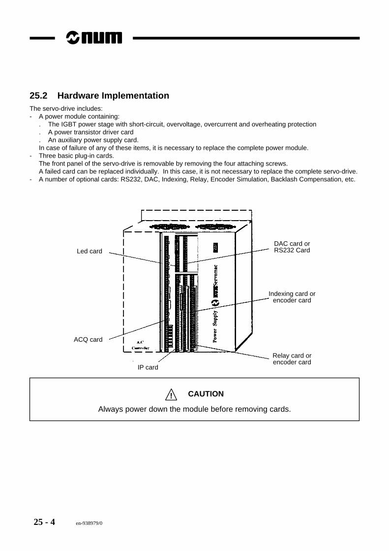
25 - 4 en-938979/0
25.2 Hardware ImplementationThe servo-drive includes:- A power module containing:
. The IGBT power stage with short-circuit, overvoltage, overcurrent and overheating protection
. A power transistor driver card
. An auxiliary power supply card.In case of failure of any of these items, it is necessary to replace the complete power module.
- Three basic plug-in cards.The front panel of the servo-drive is removable by removing the four attaching screws.A failed card can be replaced individually. In this case, it is not necessary to replace the complete servo-drive.
- A number of optional cards: RS232, DAC, Indexing, Relay, Encoder Simulation, Backlash Compensation, etc.
Led card
ACQ card
IP card
DAC card orRS232 Card
Indexing card orencoder card
Relay card orencoder card
! CAUTION
Always power down the module before removing cards.
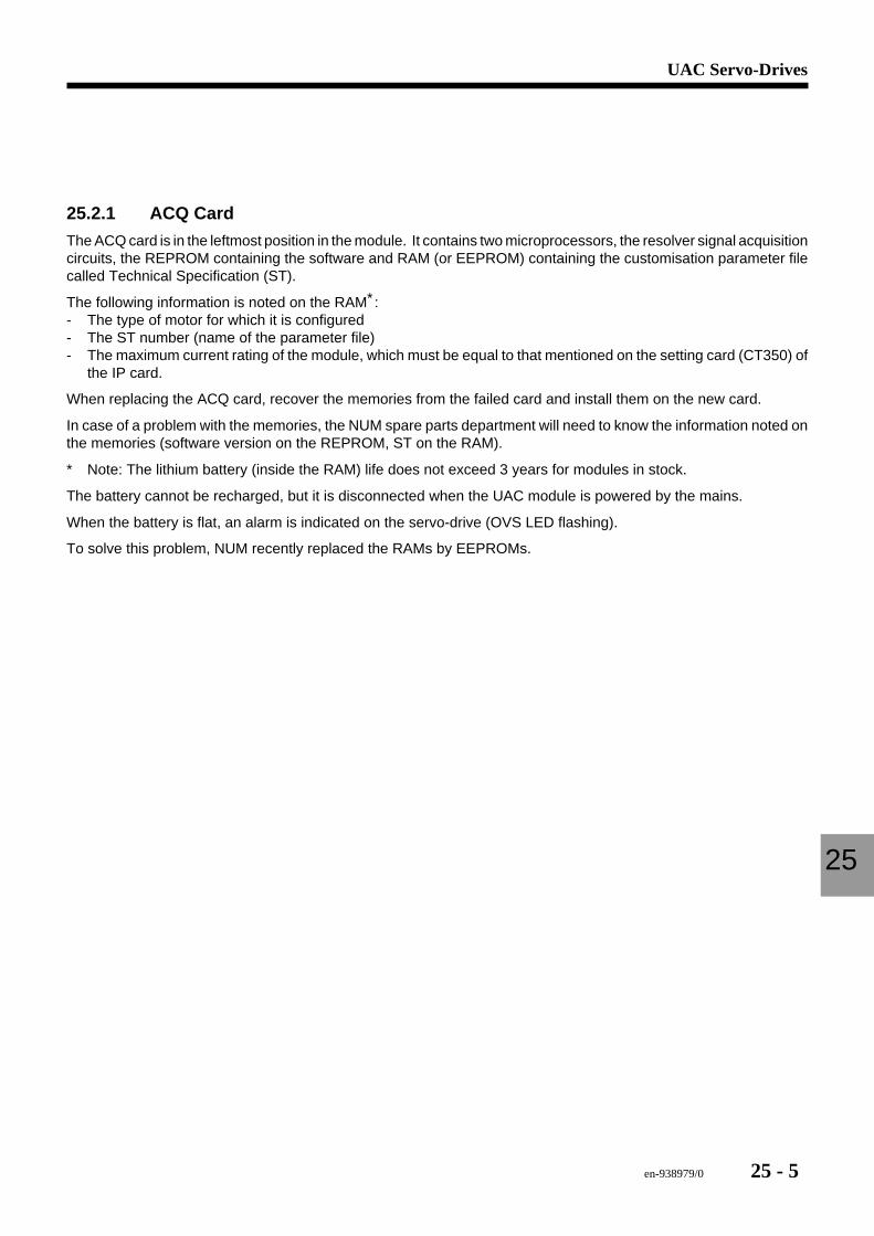
en-938979/0 25 - 5
UAC Servo-Drives
25
25.2.1 ACQ Card
The ACQ card is in the leftmost position in the module. It contains two microprocessors, the resolver signal acquisitioncircuits, the REPROM containing the software and RAM (or EEPROM) containing the customisation parameter filecalled Technical Specification (ST).
The following information is noted on the RAM∗:- The type of motor for which it is configured- The ST number (name of the parameter file)- The maximum current rating of the module, which must be equal to that mentioned on the setting card (CT350) of
the IP card.
When replacing the ACQ card, recover the memories from the failed card and install them on the new card.
In case of a problem with the memories, the NUM spare parts department will need to know the information noted onthe memories (software version on the REPROM, ST on the RAM).
∗ Note: The lithium battery (inside the RAM) life does not exceed 3 years for modules in stock.
The battery cannot be recharged, but it is disconnected when the UAC module is powered by the mains.
When the battery is flat, an alarm is indicated on the servo-drive (OVS LED flashing).
To solve this problem, NUM recently replaced the RAMs by EEPROMs.
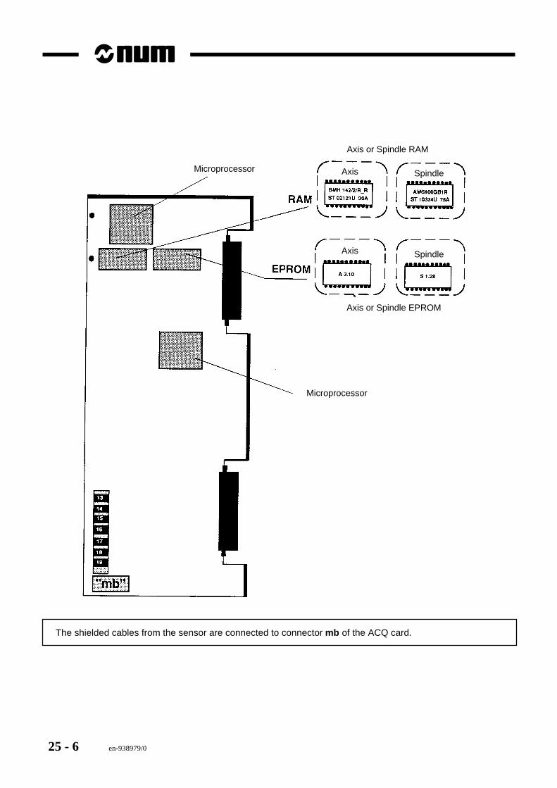
25 - 6 en-938979/0
Microprocessor
Microprocessor
Axis or Spindle EPROM
Axis or Spindle RAM
Axis
Axis
Spindle
Spindle
The shielded cables from the sensor are connected to connector mb of the ACQ card.
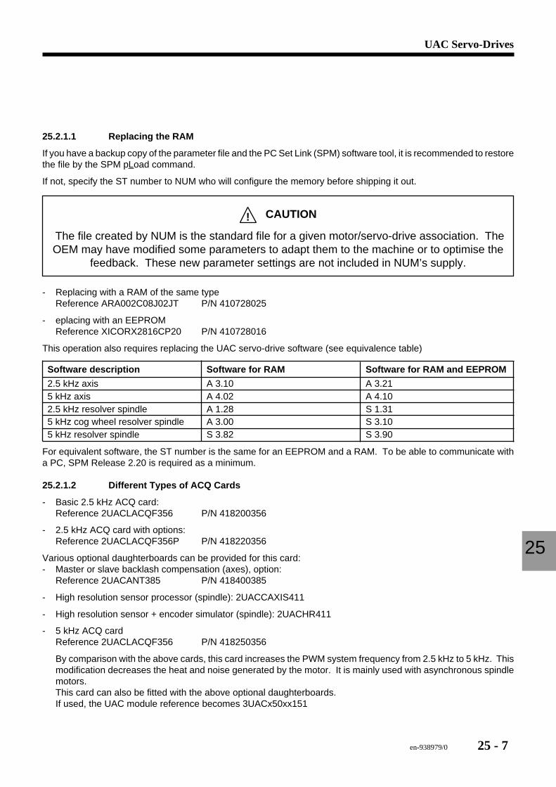
en-938979/0 25 - 7
UAC Servo-Drives
25
25.2.1.1 Replacing the RAM
If you have a backup copy of the parameter file and the PC Set Link (SPM) software tool, it is recommended to restorethe file by the SPM pLoad command.
If not, specify the ST number to NUM who will configure the memory before shipping it out.
! CAUTION
The file created by NUM is the standard file for a given motor/servo-drive association. TheOEM may have modified some parameters to adapt them to the machine or to optimise the
feedback. These new parameter settings are not included in NUM’s supply.
- Replacing with a RAM of the same typeReference ARA002C08J02JT P/N 410728025
- eplacing with an EEPROMReference XICORX2816CP20 P/N 410728016
This operation also requires replacing the UAC servo-drive software (see equivalence table)
Software description Software for RAM Software for RAM and EEPROM
2.5 kHz axis A 3.10 A 3.215 kHz axis A 4.02 A 4.102.5 kHz resolver spindle A 1.28 S 1.315 kHz cog wheel resolver spindle A 3.00 S 3.105 kHz resolver spindle S 3.82 S 3.90
For equivalent software, the ST number is the same for an EEPROM and a RAM. To be able to communicate witha PC, SPM Release 2.20 is required as a minimum.
25.2.1.2 Different Types of ACQ Cards
- Basic 2.5 kHz ACQ card:Reference 2UACLACQF356 P/N 418200356
- 2.5 kHz ACQ card with options:Reference 2UACLACQF356P P/N 418220356
Various optional daughterboards can be provided for this card:- Master or slave backlash compensation (axes), option:
Reference 2UACANT385 P/N 418400385
- High resolution sensor processor (spindle): 2UACCAXIS411
- High resolution sensor + encoder simulator (spindle): 2UACHR411
- 5 kHz ACQ cardReference 2UACLACQF356 P/N 418250356
By comparison with the above cards, this card increases the PWM system frequency from 2.5 kHz to 5 kHz. Thismodification decreases the heat and noise generated by the motor. It is mainly used with asynchronous spindlemotors.This card can also be fitted with the above optional daughterboards.If used, the UAC module reference becomes 3UACx50xx151
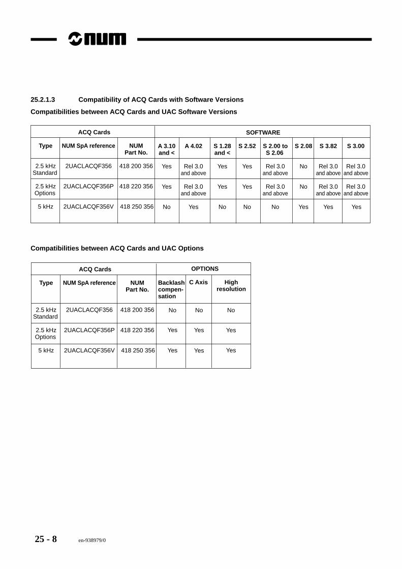
25 - 8 en-938979/0
25.2.1.3 Compatibility of ACQ Cards with Software Versions
Compatibilities between ACQ Cards and UAC Software Versions
ACQ Cards
Type NUM SpA reference NUMPart No.
2.5 kHz 2UACLACQF356 418 200 356Standard
2.5 kHz 2UACLACQF356P 418 220 356Options
5 kHz 2UACLACQF356V 418 250 356
SOFTWARE
A 3.10 A 4.02 S 1.28 S 2.52 S 2.00 to S 2.08 S 3.82 S 3.00and < and < S 2.06
Yes Rel 3.0 Yes Yes Rel 3.0 No Rel 3.0 Rel 3.0and above and above and above and above
Yes Rel 3.0 Yes Yes Rel 3.0 No Rel 3.0 Rel 3.0and above and above and above and above
No Yes No No No Yes Yes Yes
Compatibilities between ACQ Cards and UAC Options
ACQ Cards
Type NUM SpA reference NUMPart No.
2.5 kHz 2UACLACQF356 418 200 356Standard
2.5 kHz 2UACLACQF356P 418 220 356Options
5 kHz 2UACLACQF356V 418 250 356
OPTIONS
Backlashcompen-sation
C Axis Highresolution
No
Yes Yes Yes
YesYesYes
No No
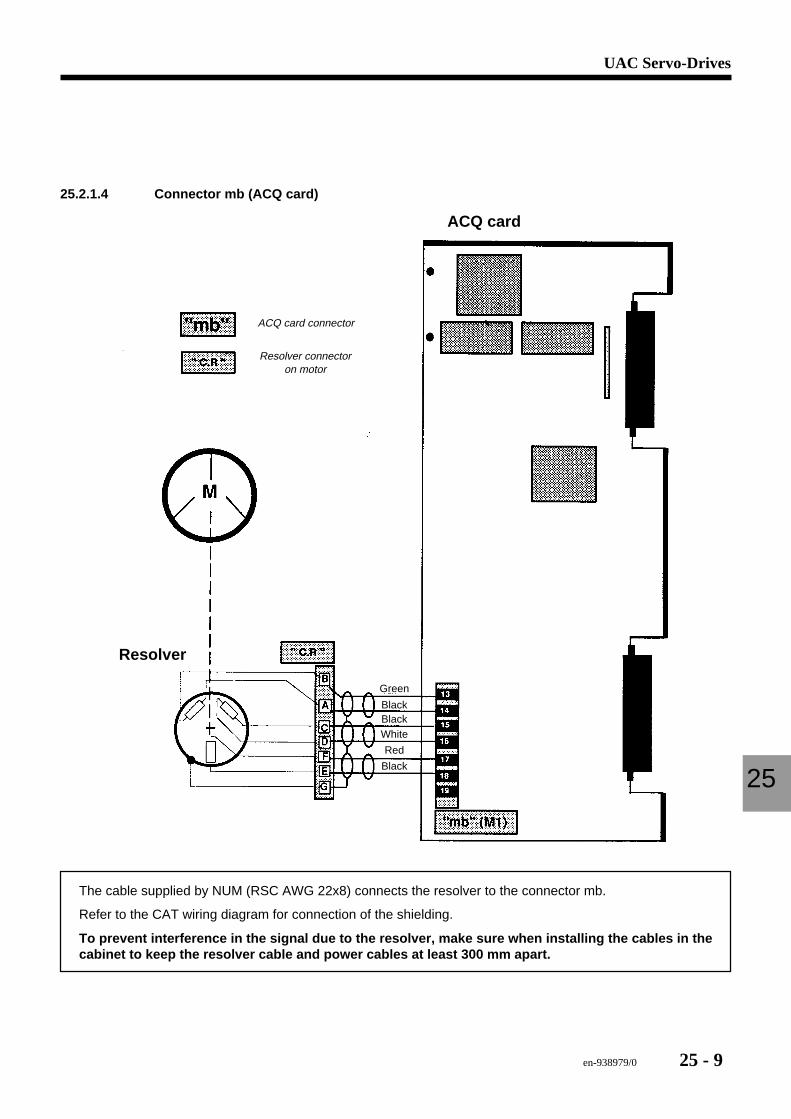
en-938979/0 25 - 9
UAC Servo-Drives
25
25.2.1.4 Connector mb (ACQ card)
ACQ card
Resolver
ACQ card connector
Resolver connector on motor
Green
BlackBlackWhite
Red
Black
The cable supplied by NUM (RSC AWG 22x8) connects the resolver to the connector mb.
Refer to the CAT wiring diagram for connection of the shielding.
To prevent interference in the signal due to the resolver, make sure when installing the cables in thecabinet to keep the resolver cable and power cables at least 300 mm apart.
25 - 10 en-938979/0
25.2.2 IP1 Card
Reference: 2UACLIPF349 P/N 418201349
(UAC Manual 783E003/C, page 19)
Connections (see UAC manual, pages 34, 35, 36).
25.2.3 AL1 LED Card
Référence: 2UACLF353 P/N 418200353
The AL1 card is located at the top of the module, to the right of the ACQ card.
It includes the UAC servo-drive status and alarm LEDs (see Maintenance below) as well as the regulators for theauxiliary outputs (+5 V, +15 V, -15 V, +24 V).
25.2.4 Optional Cards
Optional cards can be placed to the right of the IP card (bottom) and the LED card (top).
Two slots (for UAC 5030) or four slots (for other modules) are available for optional cards.
There are no predefined slots for the optional cards.
The following optional cards are available:- Standard relay card: 2UACG14 P/N 418414386- Relay + current limiting card: 2UACG15 P/N 418415386- Indexing card: 2UACPOS1 P/N 418400386- Encoder card: 2UACENC387x
x specifies the card resolution:x = A: 768 pulses per revolution P/N 418401387= B: 3072 pulses per revolution P/N 418400387 (standard)= C: 12,288 pulses per revolution P/N 418402387= D: 49,152 pulses per revolution P/N 418403387
These cards are described in detail in the UAC Installation and Maintenance Manual 738E003/C, pages 38-51.
They are not detailed further herein.
However, two optional cards are required for maintenance of the UAC servo-drives.
25.2.4.1 RS232 Serial Interface Card
Reference: 2AUC232 P/N 418400372
This card interfaces the UAC servo-drive with a PC.
It also allows connection of the PC Set Link servo-drive setup software (SPM software) running under DOS.
This software is described in detail in the PC Set Link Manual 738E0.
The SPM software is used to set up the servo-drive and optimise the customisation parameters (ST): servo-driveconfiguration, optimisation of the speed loop, adaptation of the options.
It is also used to control the motor from the PC and provides an internal oscilloscope function.
This software is essential for setup and can also be useful for maintenance.
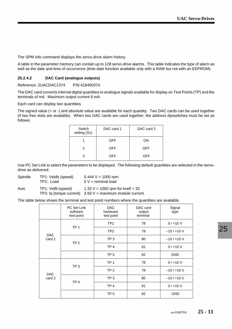
en-938979/0 25 - 11
UAC Servo-Drives
25
The SPM Info command displays the servo-drive alarm history.
A table in the parameter memory can contain up to 128 servo-drive alarms. This table indicates the type of alarm aswell as the date and time of occurrence (time-date function available only with a RAM but not with an EEPROM).
25.2.4.2 DAC Card (analogue outputs)
Reference: 2UACDAC1374 P/N 418400374
The DAC card converts internal digital quantities to analogue signals available for display on Test Points (TP) and theterminals of md. Maximum output current 6 mA.
Each card can display two quantities.
The signed value (+ or -) and absolute value are available for each quantity. Two DAC cards can be used together(if two free slots are available). When two DAC cards are used together, the address dipswitches must be set asfollows:
Switch DAC card 1 DAC card 2setting (S1)
1 OFF ON
2 OFF OFF
3 OFF OFF
Use PC Set Link to select the parameters to be displayed. The following default quantities are selected in the servo-drive as delivered:
Spindle TP1: Veldb (speed) 0.444 V = 1000 rpmTP2: Load 5 V = nominal load
Axis TP1: Velfil (speed) 1.33 V = 1000 rpm for kvelf = 32TP2: Iq (torque current) 3.93 V = maximum module current
The table below shows the terminal and test point numbers where the quantities are available.
PC Set Link DAC DAC card Signalsoftware hardware output typetest point test point terminal
TP1 78 0 / +10 VTP 1
TP2 79 –10 / +10 VDACcard 1 TP 3 80 –10 / +10 V
TP 2TP 4 81 0 / +10 V
TP 5 82 GND
TP 1 78 0 / +10 VTP 3
TP 2 79 –10 / +10 VDACcard 2 TP 3 80 –10 / +10 V
TP 4TP 4 81 0 / +10 V
TP 5 82 GND
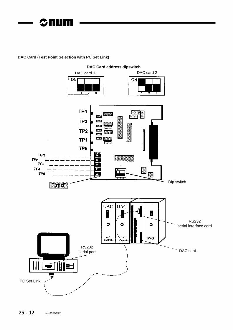
25 - 12 en-938979/0
DAC Card (Test Point Selection with PC Set Link)
DAC Card address dipswitch
DAC card 1 DAC card 2
DAC card
RS232serial interface card
RS232serial port
PC Set Link
Dip switch

en-938979/0 25 - 13
UAC Servo-Drives
25
With the SPM software, you can modify the assignments of the test points measured on the cards.
The quantities selected can be displayed on the DAC card, on the internal oscilloscope of SPM and dynamically onthe SPM software (command dtEp).
The standard quantities (current, axis speed, power and spindle speed) are used to check the behaviour of an axis.
However, other quantities can be selected during maintenance to check the resolver (e-cos-r, e-sin-r, e-gain) or itsangular setting (Vd) (see the section on axis motors for the setting procedure).
Most of the other quantities that can be tested are for use by NUM S.A. for servo-drive design.
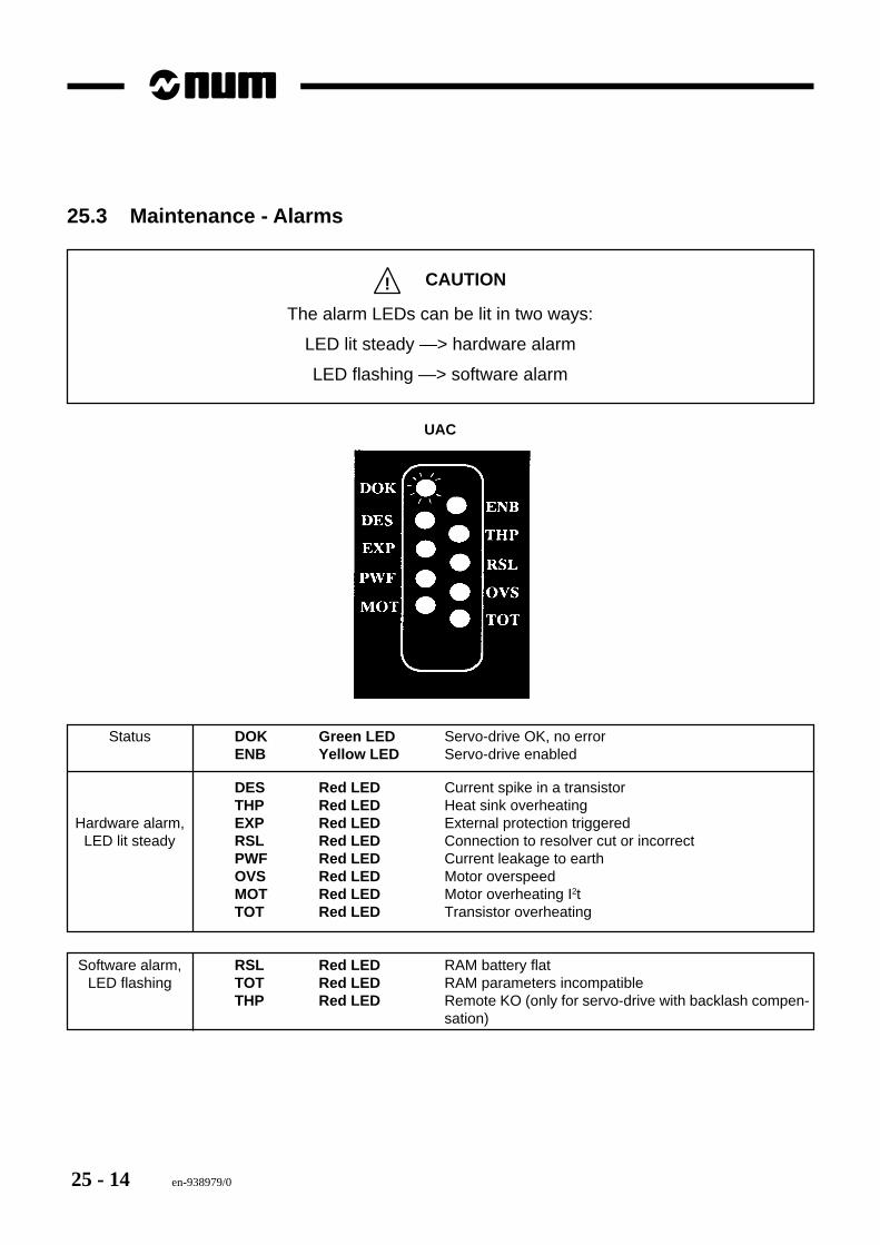
25 - 14 en-938979/0
25.3 Maintenance - Alarms
! CAUTION
The alarm LEDs can be lit in two ways:
LED lit steady —> hardware alarm
LED flashing —> software alarm
UAC
Status DOK Green LED Servo-drive OK, no errorENB Yellow LED Servo-drive enabled
DES Red LED Current spike in a transistorTHP Red LED Heat sink overheating
Hardware alarm, EXP Red LED External protection triggeredLED lit steady RSL Red LED Connection to resolver cut or incorrect
PWF Red LED Current leakage to earthOVS Red LED Motor overspeedMOT Red LED Motor overheating I2tTOT Red LED Transistor overheating
Software alarm, RSL Red LED RAM battery flatLED flashing TOT Red LED RAM parameters incompatible
THP Red LED Remote KO (only for servo-drive with backlash compen-sation)
en-938979/0 25 - 15
UAC Servo-Drives
25
25.3.1 Clearing Stored Alarms
When an fault triggering an alarm occurs:- The green DOK (drive OK) and yellow ENB (drive enabled) LEDs go out- The DOK contact on terminals 1 and 2 of connector ma on the IP card opens- The alarm LED comes on- The alarm is stored- The motor stops by inertia.
To start operation, proceed as follows:- Power down and wait for around 30 seconds- Power up (the DOK and alarm LED concerned are lit)- Check the type of alarm stored- Correct the problem- Clear the alarm by enabling then disabling the servo-drive. (The alarm can also be cleared by applying power to
and removing it from terminal 20 of the IP card).
If the alarm disappears and DOK remains lit, the drive is OK. Otherwise, the alarm persists.
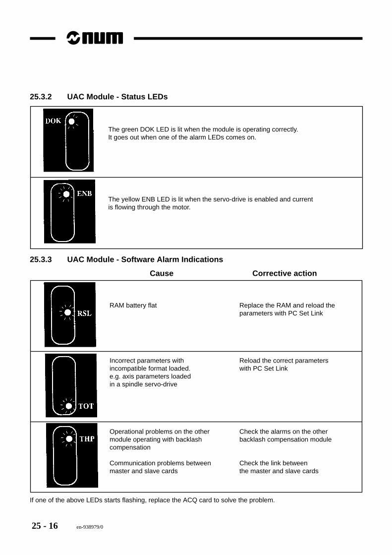
25 - 16 en-938979/0
25.3.2 UAC Module - Status LEDs
The green DOK LED is lit when the module is operating correctly. It goes out when one of the alarm LEDs comes on.
The yellow ENB LED is lit when the servo-drive is enabled and current is flowing through the motor.
25.3.3 UAC Module - Software Alarm Indications
Cause Corrective action
RAM battery flat Replace the RAM and reload theparameters with PC Set Link
Incorrect parameters with Reload the correct parametersincompatible format loaded. with PC Set Linke.g. axis parameters loadedin a spindle servo-drive
Operational problems on the other Check the alarms on the othermodule operating with backlash backlash compensation modulecompensation
Communication problems between Check the link between master and slave cards the master and slave cards
If one of the above LEDs starts flashing, replace the ACQ card to solve the problem.
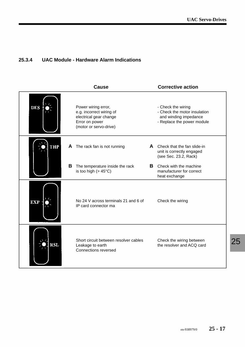
en-938979/0 25 - 17
UAC Servo-Drives
25
25.3.4 UAC Module - Hardware Alarm Indications
Cause Corrective action
Power wiring error, - Check the wiringe.g. incorrect wiring of - Check the motor insulationelectrical gear change and winding impedanceError on power - Replace the power module(motor or servo-drive)
A The rack fan is not running A Check that the fan slide-in unit is correctly engaged
(see Sec. 23.2, Rack)
B The temperature inside the rack B Check with the machine is too high (> 45°C) manufacturer for correct
heat exchange
No 24 V across terminals 21 and 6 of Check the wiringIP card connector ma
Short circuit between resolver cables Check the wiring between Leakage to earth the resolver and ACQ cardConnections reversed
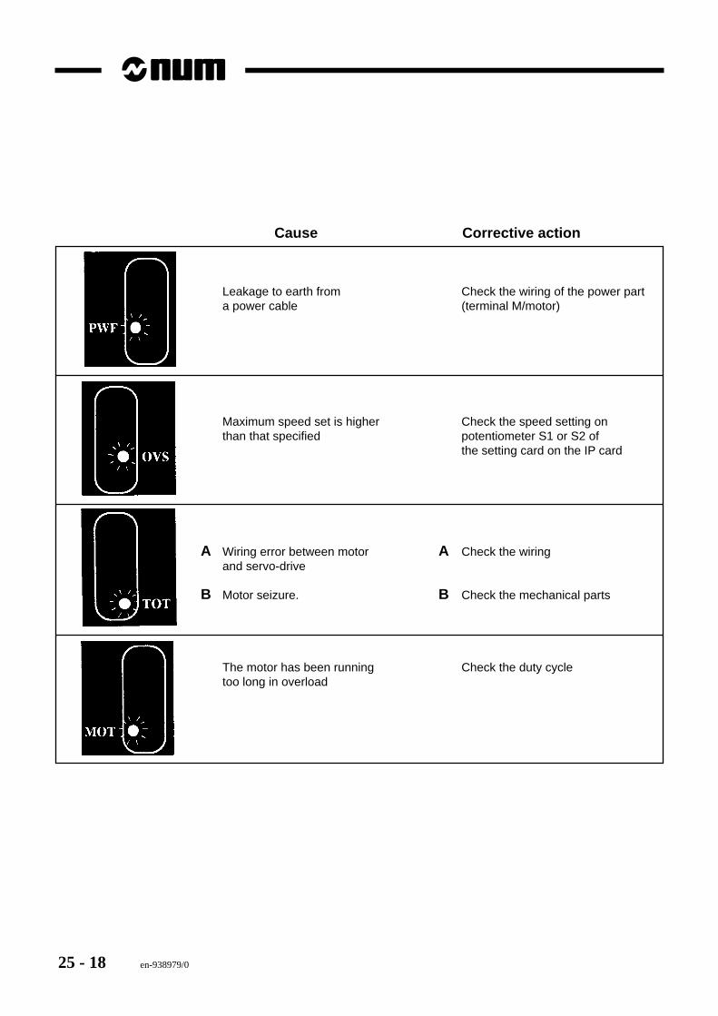
25 - 18 en-938979/0
Cause Corrective action
Leakage to earth from Check the wiring of the power parta power cable (terminal M/motor)
Maximum speed set is higher Check the speed setting onthan that specified potentiometer S1 or S2 of
the setting card on the IP card
A Wiring error between motor A Check the wiringand servo-drive
B Motor seizure. B Check the mechanical parts
The motor has been running Check the duty cycletoo long in overload


![[4] num integration](https://img.pdfslide.us/doc/110x75/547f2284b4af9ffd248b4658/4-num-integration.jpg)