Embed Size (px)
Citation preview

Operating manual
NUEVO
27.09.2010
Also for models with natural refrigerant (NR)
Also for FB (flat built) models
Valid for: Table models Unistat Tango Nuevo, Unistat Tango Nuevo wl, Unistat Tango w Unistat 405, Unistat 405w Unistat 705, Unistat 705w Freestanding models Unistat 410w, 425, 425w, 430, 430w, 510w Unistat 510, 515w, 520w, 525w, 530w Unistat 610, 610w, 615, 615w, 620w, 625w Unistat 630, 630w, 635w Unistat 640, 640w, 650w Unistat 815, 815w, 825, 825w Unistat 905, 905w, 910, 910w, 912w, 915w Unistat 920w, 925w, 930w Unistat 950, 950w Unistat 1005w Unistat 1015w


2
Contents V1.4/09.10 // software: V05.10.001
Foreword ............................................................................................................4 Chapter 1: Safety ................................................................................................5 Description of Safety and Information symbols ........................................................6 Intended Use and General Safety Instructions..........................................................7 Description .........................................................................................................8 Duties of responsible person .................................................................................9 Operator requirements..........................................................................................9 Machine operator duties .......................................................................................9 Work area...........................................................................................................9 Safety Devices to DIN12876...............................................................................10 Additional Protection Devices ..............................................................................11 Environmental Conditions....................................................................................12 Operating conditions ..........................................................................................13 Location ...........................................................................................................14 Thermal fluids ...................................................................................................15 Chapter 2: Electronics and operation ....................................................................16 Unistat Control and Unistat Pilot ..........................................................................17 Unistat flow diagram..........................................................................................18 Information Displays...........................................................................................19 Description of individual Fields.............................................................................20 Real-time clock ..................................................................................................22 Event Function ..................................................................................................22 Operation..........................................................................................................23 Operation using the key / rotary knob...................................................................24 Operation using the simulated Number Pad ...........................................................25 Operation using the simulated Number Pad ...........................................................25 Main menu........................................................................................................26 Program creator.................................................................................................29 Control parameters ............................................................................................31 Comfort menu ...................................................................................................35 ComG@te menu ................................................................................................42 Function Numbers and their meaning....................................................................48 User menu – config............................................................................................54 User menu - select .............................................................................................55 Chapter 3: Connect the machine, fill and prepare for the required application ............56 Power connection ..............................................................................................57 Safety instructions.............................................................................................57 Transport protection...........................................................................................57 Remote control for winter operation and outdoor versions.......................................58 Start up............................................................................................................59 Water-cooling....................................................................................................60 Connecting an externally closed application (reactor)..............................................61 Connecting an externally open (bath) application ...................................................62 Switching on the temperature control unit ............................................................63 Setting the over-temperature switch.....................................................................63 Setting the level indicating meter with capacitive level identification ........................66

3
Setting the set-point limits ..................................................................................68 Entering a set-point ............................................................................................68 Starting Temperature Control ..............................................................................69 Filling an externally closed system .......................................................................70 Air purging an externally closed application ...........................................................73 Degassing an externally closed application ............................................................74 Filling an externally open application ....................................................................75 Draining the machine and an externally closed application.......................................78 Changing thermal fluid / internal cleaning..............................................................79 Chapter 4: Interface and software update .............................................................81 ComG@te.........................................................................................................82 Digital Interface with additional NAMUR-Commands...............................................85 Chapter 5: First aid for a fault condition................................................................87 Messages .........................................................................................................88 Display Error Messages.......................................................................................89 Alarm and Warning codes ...................................................................................90 Soft- (resetable) alarms.......................................................................................93 Exchange of the electronics ................................................................................94 Maintenance .....................................................................................................95 Decontamination / Repair ....................................................................................96 Cleaning the surfaces .........................................................................................96 Checking the pump seal......................................................................................96 Plug contacts ....................................................................................................96 Chapter 6: Taking the machine out of service........................................................97 Decommissioning...............................................................................................98 Transport..........................................................................................................99 Disposal ...........................................................................................................99

4
Foreword Dear Customer, The Huber team would like to thank you for ordering this product. You have made a good choice. We thank you for your trust! Please read and understand the instruction manual thoroughly before operating the unit. All instructions and safety information must be complied with. Please read this manual before transporting, commissioning, operating, maintaining, repairing, storing or disposing of this unit. Failure to comply with the instructions within this manual may invalidate any warranty for this unit.

5
Chapter 1: Safety In this chapter is to be found the following sections:
- Description of safety and information symbols - Intended use and General Safety Information - Description - Duties of the responsible person - Operator requirements - Machine operator duties - Work area - Safety Devices to DIN 12876 (applicable for units with heating) - Additional Protection Devices (if provided) - Environmental conditions - Operating conditions - Location - Thermal fluids
6
Description of Safety and Information symbols
Safety information is shown with a pictogram and keyword. The keyword indicates the level of the corresponding danger.
Danger!
Immediate risk to the life and health of personnel (Serious injury or death).
Warning!
Possible risk to the life and health of personnel (Serious injury or death).
Caution!
Possible dangerous situation (possible injury to personnel or damage to property).
Information!
User-tips and other useful information.
Requirement!
Requirement to carry out a specific method, or action, for safe machine operation.
Information in association with EX p Cabinet (only valid for Unistat Nuevos)

7
Intended Use and General Safety Instructions
Danger! Non-intended use can result in considerable personal injuries and material damage. No third persons are authorized to make any changes to the machine. The device declaration becomes void, if any modification is carried out without manufacturers consent. Only personnel trained by the manufacturer may carry out modifications, repairs or maintenance work. The following must be observed: Always use the machine in a perfect working condition! Only expert personnel may initially start-up and repair the device! Do not bypass, bridge-over, dismantle or switch off the safety mechanisms!
The manufacturer is not liable for damages caused by technical changes to the temperature control device, inappropriate handling and / or use of the temperature control device without regard to the operating instructions. The temperature control device is manufactured for commercial use only and may only be used to maintain the temperature of reactors or other professionally expedient objects in laboratories and industry. Suitable thermal fluids are used throughout the entire system. The cooling or heating power is provided at the pump connections. The technical specifications of the device are determined in data sheet. Operation must be prepared and carried out according to the operating instructions. Any non-observance of the operating instructions is considered as non-intended use. The temperature control device corresponds to the state-of-the-art and the recognized safety-related regulations. Safety devices are built into your temperature control device. The device is NOT approved for use as a medical product!
Without an Ex-p cabinet, this machine is NOT built as explosion-proof and is NOT suitable for use in ATEX areas! If used in association with an Ex-p cabinet it is essential that the attached notices (ATEX) are observed and followed. This attachment is only available when the unit is ordered together with an Ex-p cabinet. If this attachment is not provided, please contact the Customer Service of Peter Huber Kältemaschinenbau GmbH immediately. Foreseeable non-intended use:
- Activate the brakes for machines with rollers or roller support.

8
Description Unistats are highly responsive temperature control machines that have been designed to be used with either external closed (e.g. jacketed reactors) or for external open (e.g. calibration baths) applications. Unlike conventional “open-bath” or “re-circulating thermostats”, Unistats contain no internal bath. Due to the low internal volume combined with high performance refrigeration and heating technology, a very short cooling and heating time compared with conventional bath technology can be achieved. Instead of a bath, as used in conventional bath and circulation thermostats which is also used to accommodate the expansion of the thermal fluid with temperature, we use a passive temperature controlled expansion vessel. With the integrated speed controlled pump fitted in the table models and some floor standing models, it is possible to control flow and / or pressure of the thermal fluid and thus can be exactly adapted for the required application. With floor standing models using larger pumps and cooling powers, this function is taken over by an external optional VPC-module. With help of the self optimising cascade controller, you obtain the optimum control results under steady state conditions as well as by set-point changes and with exothermic reactions. One can choose between aperiodic or with a small overswing (faster) control. Information and temperature development can be easily read via the large graphic display screen (with touch screen) as well as give command inputs. A comfortable menu guidance eases the operation of the machine. With help of the digital interfaces RS232, RS485, the analogue 0/4-20 mA or 0-10V interface as well as various digital in and output possibilities (all according to the NAMUR), and fitted as standard, the machine can be fitted without problem into many laboratory automation systems The removable Unistat Pilot can be used as a remote control External temperature control requirements can be easily met via the external Pt100 connection (NAMUR standard) The integrated temperature-ramp function as well as the internal programmer underline the high level of operator comfort. The integrated programmer offers the possibility to make and then call up 10 temperature programs with a maximum of 100 steps. The thermostat uses an over temperature protection in accordance with DIN EN 61010-2-010, which is independent of the actual control circuits

9
Duties of responsible person
The operating instruction is to be kept easily accessible and in immediate vicinity of the unit. Only suitably qualified personnel should operate this unit. Personnel should be properly trained before operating the unit. Make sure that the operators have read and understood the instruction manual. Supply appropriate Personal Protective Equipment as required.
Operator requirements
Only authorised personnel should operate this unit. Personnel should be properly trained before operating the unit. The minimum age for operators is 18 years. Personnel under 18 years should only operate the unit under the direct supervision of qualified personnel. The operator is responsible for third parties within the working area.
Machine operator duties
Make sure that the operators have read and understood the instruction manual. Please observe the safety instructions. Appropriate Personal Protective Equipment (e.g. safety goggles, safety gloves) should be worn when operating the unit.
Work area Work area is defined as the area in front of the machines control panel. Work area is determined by the peripheral equipment connected by the operator. It is the customer’s responsibility to ensure a clear, safe working area around the temperature control unit. The arrangement of the work area should be made after considering access to, and risk assessment of, the area and application.

10
Safety Devices to DIN12876
- Low level switch - Adjustable over-temperature switch (also valid for chillers with heating)
Classification of Laboratory Thermostats and Baths Classification Thermal Fluid Technical requirement Designation d I non-flammable a Over-temperature cut-off c NFL II Adjustable over-temperature cut-off flammable b FL III Adjustable over-temperature cut-off
and extra low-level switch
a Normally water; other fluids only when they are non-flammable in the event of a single Failure. b The thermal fluid must have a flame point ≥ 65 °C, this means that ethanol can only be used under constant supervision. c The over-temperature protection can for example be provided by a fluid sensor or a suitable over temperature switch. d Determined by the manufacturer. Your temperature control unit is designated a Class III FL. ELO: Electronic Over-temperature Switch This temperature control unit is equipped with an electronic over-temperature switch. Temperature sensors are built in for the fluid outlet temperature and the temperature in the expansion vessel. There is a simple method of entering the triggering temperature for each sensor. A mechanical tool is no longer required to change the over-temperature settings. The over-temperature switch can only be adjusted after the user has re-entered a code displayed on the Unistat Pilot´s display. This procedure avoids unintentional changes being made to the setting and replaces a mechanical tool by software.

11
A new feature is the Process Safety function. This function provides further protection for the operators and application. A classic over-temperature device unit would trip and cause a shutdown if over-temperature cut-off temperature was reached. This could occur under circumstances where more heat was being generated by a process (exothermic) than the unit could remove. Switching the temperature control unit off would remove the only possible method of cooling the application down. Consequently, the temperature would be able to further increase, creating a risk of injury to personnel or damage to the application, for example by over-heating a liquid into pressurised vapour. Using the Process Safety function, the controller recognises when the over-temperature cut-off is reached, and switches the cooling on. The compressor automatic is automatically set to always on. Even if the temperature continues to rise, the refrigeration machine will increase its cooling to maximum to minimise the heating.
Additional Protection Devices
- Auto-Start function - Alarm function - Warning messages - General unit messages
Danger! Emergency Procedure: Disconnect Electrical Power! Turn the Mains isolator (36) to “0”! Dangerous liquid / vapours from temperature control unit or connected hoses (very hot, very cold, dangerous chemicals) and / or fire / explosion / implosion: Evacuate the area, following local regulations and procedures to prevent injury or loss of life! Refer to the MSDS Safety information for the thermal fluid concerned!
12
Environmental Conditions
This unit, and operations, will comply with DIN EN 61010-1:2001, only when it is located in suitable environmental conditions.
- for indoor use only; - installation site ≤ 2000 m altitude; - installed on a level, even, non flammable surface; - maintain a clearance above and around the unit of 10 cm for water-cooled units,
and 20cm for air-cooled units, to allow air to circulate around the unit; - for ambient temperature conditions please refer to the technical data sheet;
remaining within these ambient conditions is imperative in ensuring accurate operation;
- maximum relative humidity of 80% up to 32°C, decreasing linearly to 50% relative humidity at 40°C
- use only as long a power cord as necessary; - the unit should be located so as not to restrict access to the mains power
switch; - mains voltage should be ±10% of the rated value; - avoid voltage spikes; - transient voltage surges as they occur normally in the supply grid; - clean rating 2; - overvoltage category II

13
Operating conditions
Please make sure that the application and system performance is dependent upon the temperature range, viscosity, and flow rate of the thermal fluid:
- Please ensure that the power supply connections are correctly dimensioned. - The temperature control device should be located so, that sufficient fresh air
is available even when working with water cooled units. - Please note that hose connections should be compatible with the thermal
fluid used and the working conditions. - When choosing the thermal fluid, not only minimal and maximum
temperatures have to be complied with but also have to be suitable regarding burn point, viscosity and / or freezing. Furthermore the thermal fluid has to be compatible with all the materials used in the unit.
- Pressure changes with the length of hoses (keep as short as possible). Choose as large a diameter of hoses as possible (the width of the pump connections are considered as a point of reference) and may negatively affect temperature control results. Flow restrictions may occur if a too narrow connector is selected for corrugated hoses.
- Do not use water, mixtures of water and anti-freezer as thermal fluid. - The use of unsuitable hoses or hose connections may cause thermal and
toxic injury to personal and environment. Temperature control hoses and their connections have to be insulated / secured against contact / mechanical damage.
- Non-suitable thermal fluids can negatively affect temperature control and be the cause of negative temperature results and damages. Therefore only use the thermal fluids recommended by the manufacturer and only in the intended temperature and pressure range. The application should be located on approximately the same level or lower than the temperature control device, if temperature control is to be carried out near to the boiling temperature of the thermal fluid. The thermal fluid should have room temperature when filling. Fill in the thermal fluid slowly, carefully and steadily. At the same time make sure that no thermal fluid overflows (back pressure); it is thereby necessary to wear personal protective equipment, e.g. safety goggles, thermally and chemically resistant gloves, etc.
- After filling and setting all necessary parameters the thermoregulation circuit has to be degassed. This is a requirement for proper operation of the device and thus its application.
- In the case of pressure-sensitive applications, e.g. glass reactors, observe the maximum inlet pressure of the temperature control device for cross section reduction or shut-off (see data sheet). Take suitable precautions (e.g. pressure limitation for temperature control devices with pressure control, bypass).
- In order to avoid danger of overpressure in the system, which could damage the temperature control device or the application, the thermal fluid must always be adapted at room temperature before turning off and a possibly available shut-off valve must be left open (pressure compensation).

14
- Temperature and dynamics within the reactor are determined by the outlet temperature. A differential temperature is created (delta T) between outlet temperature and the temperature within the reactor. This difference in temperature has to be adapted, depending upon type of glass application. As the differential temperature may exceed the admissible limit values and bursts may occur. Delta T value has to be adapted to the corresponding application. Therefore please see chapter on Comfort menu
- Do not kink the hoses. - Check hoses in regular intervals for material fatigue (e.g. cracks).
With water cooled units please pay special attention to the maximum operating temperature and differential pressure requirements for the cooling water. Therefore please refer to the technical data sheet.
Danger! If the cooling water contains high levels of minerals, e.g. chloride, bromide then suitable water treatment chemicals should be used. Use only recommended materials to maintain the unit warranty. Further information on corrosion, (appearance and avoidance) can be found on our website www.huber-online.com.
Please refer to the sections on Intended Use and general safety instructions.
Location
Caution! - Transport the unit upright - The unit should be mounted in an upright and secure position, on a solid, stable
surface - Place on a non flammable surface - Keep the area around the unit clean, to avoid slip and trip hazards - Set the brakes on the castors once the unit is in position - Place suitable absorbent material under the unit to catch any condensate and
thermal fluid spills - Any spillage of thermal fluid should be immediately cleaned up - For large units, check the weight / load capacity for the flooring

15
Thermal fluids
We recommend the thermal fluids shown in our catalogue. The name of a thermal fluid is derived from the working temperature range and the viscosity at 25 °C. Examples of thermal fluids in our catalogue: M40.165.10:
• Lower working limit -40 °C • Upper working limit 165 °C • Viscosity at 25 °C: 10 mm2/s
The data sheet for the thermal fluid used is of utmost importance, and must be read before use. This data sheet should be followed.
• Please note the classification of your machine according to DIN 12876 • The chosen thermal fluid must be compatible with stainless steel 1.4301 (V2A)
and FKM! • The maximum viscosity of the thermal fluid may not exceed 50 mm²/s at the
lowest temperature reached! • The maximum density of the thermal fluid may not exceed 1kg / dm³
Please note:
• For our units we recommend covering with inert gas. Therefore we offer the sealing set listed in our Huber-Catalogue, valid for unistats of the 3rd generation.
16
Chapter 2: Electronics and operation The following sections are to be found in this chapter:
- Unistat Control and Unistat Pilot - Information display - Real time clock - Operation - Operation using the rotary knob - Operation using the simulated Number Pad - Main menu options - Comfort menu - Compact menu - ComG@te menu - Function numbers and their meaning - Configure user menus - Select user menus
17
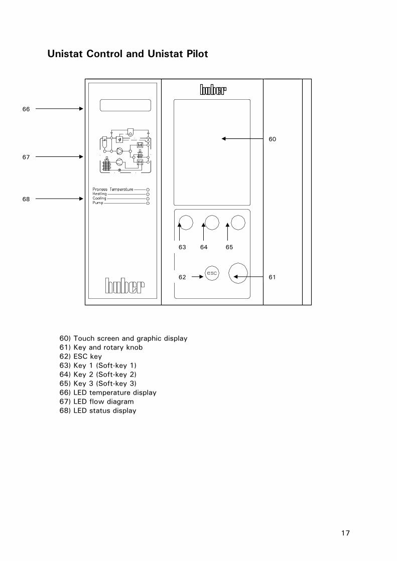
Unistat Control and Unistat Pilot
60) Touch screen and graphic display 61) Key and rotary knob 62) ESC key 63) Key 1 (Soft-key 1) 64) Key 2 (Soft-key 2) 65) Key 3 (Soft-key 3) 66) LED temperature display 67) LED flow diagram 68) LED status display
60
62 61
66
67
68
63 64 65

18
Unistat flow diagram Externally open application Externally closed application
Operating condition:
1. Stand by: LED 8 (when choosing jacket temperature control) or LED 10 (when choosing process temperature control) are lit.
2. Circulation is active: LEDs: 1, 2, 3, and 9 are lit. 3. Cooling active: LED 4 and 6 are lit. Only in connections with operating condition
2. 4. HT Cooling is active: LED 4 and 6 are lit. Only with operating condition 2 and for
temperature control devices with HT Cooling. 5. Heating is active: LED 7 is lit. Only in connection with operating status 2.
LED 1
LED 2 LED 3 LED 4 LED 5
LED 6
LED 7
LED 8
LED 9
LED 10
Pump
Heating
HT Cooler
Evaporator
Compressor
Condensator Stepper motor valve
Expansion vessel
19
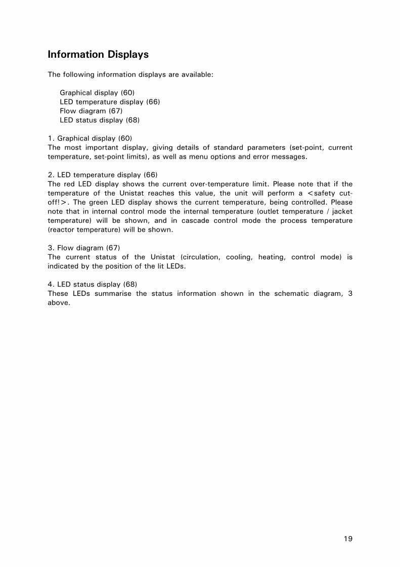
Information Displays The following information displays are available:
Graphical display (60) LED temperature display (66) Flow diagram (67) LED status display (68)
1. Graphical display (60) The most important display, giving details of standard parameters (set-point, current temperature, set-point limits), as well as menu options and error messages. 2. LED temperature display (66) The red LED display shows the current over-temperature limit. Please note that if the temperature of the Unistat reaches this value, the unit will perform a <safety cut-off!>. The green LED display shows the current temperature, being controlled. Please note that in internal control mode the internal temperature (outlet temperature / jacket temperature) will be shown, and in cascade control mode the process temperature (reactor temperature) will be shown. 3. Flow diagram (67) The current status of the Unistat (circulation, cooling, heating, control mode) is indicated by the position of the lit LEDs. 4. LED status display (68) These LEDs summarise the status information shown in the schematic diagram, 3 above.

20
Screen display (this display is reached by selecting Main Menu / Display Mode / Graphic) Please also note operating options described in chapter operation. Description of individual Fields Field 1: Display Current value This field shows the current internal temperature of the unit and, if an external sensor is connected, the current process temperature. Field 2: Display set-point This field displays the current set-point. Field 3: Display Graphic temperature This field shows the internal and process temperatures in graphical format. The span of the temperature axis is between the minimum (see field 7) and maximum set-point limits (see also field 10). Field 4: Display Status Field This field shows useful information such as the current temperature control mode (internal or process), unit operations (degassing, air-purging) and active control loops.
22.04.08 07:35.20
Funct.-no. Tsetl(F0) start
?
Tmin. -35.0
delta T 100.0
Tmax. 150.0
OT 80.00
T process 20.00 T internal 19.50
T set-point 15.00
Field 13
Field 12
Field 11
Field 10
Field 9
Field 8
Field 7
Field 6
Field 5
Field 4
Field 3
Field 2
Field 1

21
Field 5: Display Soft-keys operation This field enables various functions. Please therefore note the soft keys (63, 64, 65) located directly under the relevant touch screen buttons. The Function Number menu can be displayed by lightly touching the soft key 63 Funct.-no area of the screen. Please refer to the Function Numbers and Definitions chapter for more details. Pressing the soft key (64) Tset F(0) area of the screen will bring up the option to enter a new set-point. Pressing the soft key 65 Start of the screen will bring up the Start & Stop menu. This menu allows the temperature control, air-purging, circulation and degassing to be started as required. After an operation, the menu will return to the standard screen. Instead of the function Start in field 5 the function stop is now available. Pressing the soft key 65 Start of the screen will bring up the Start & Stop menu again. By pressing the Start area again, any operations previously started may be stopped. Field 6: Display Help Help (general information / trouble-shooting information) will be displayed. Field 7: Display Minimum set-point This field displays the current minimum set-point limit (corresponds to Funct. no. F1). The minimum set-point also serves as the lower temperature limit for the graphic temperature display, in Field 3. Field 8: Pump and Level information This field displays the level as well as pump status including pump speed indication (only for temperature control devices with speed regulation). Field 9: Display delta T This field displays the delta T value (max. admissible difference between process and internal temperature). This value may be set within a range of 0…100K under the main menu point limits / delta T limits. This field is active only with a connected process sensor and when the temperature control mode process temperature is activated. Field 10: Display maximum set-point This field displays the current maximum set-point limit (corresponds to Funct. no. F2). The minimum set-point also serves as the upper temperature limit for the graphic temperature display, in Field 3. Field 11: Display Over-temperature cut-off This field displays the current setting of the over-temperature cut-off. Please note that this value can only be changed through the Main menu Over-temperature. Please refer to the Setting the over-temperature chapter in the Main menu. Field 12: Display Alarm and Warning messages This field displays information on any alarm or warning conditions that are present. Alarm and warning messages are also immediately displayed as text in the graphic display (60). Field 13: Display Date and Time This field displays the current date and time.

22
Real-time clock Rechargeable Battery The Unistat Pilot as well as CC-Pilot (for temperature control devices with CC-Pilot) are equipped with an internal, battery-powered clock that runs even when the unit is turned off. When the unit is powered up, the actual date and time are uploaded to the unit. The capacity of the battery means allows the clock to continue to run for a number of months. If a unit has been powered-down for an extended time, it should be powered-up and left for an hour or so before running it again. If the time and date have been lost, they can be re-entered during this period. If after turning off and on again, the time and date have been reset, then it must be assumed that there is a problem with the rechargeable battery. In this case please contact our service department. Event Function The clock has a programmable event function. Using this function an operation can be set to run every day (until the function is reset in the operator menu). There are two available operations: Acoustic signal: The unit will generate an acoustic signal for about 15 seconds. Program Start: When configuring the calendar to start a program, the user will be asked for the number of the program to be started. The program will then be started at the set time and date, even if (manual) temperature control had not been previously started.

23
Operation Please note, there are multiple possibilities to operate the machine. Complete operation of the machine is possible even without the touch screen (60)
1. Operation via touch screen (60) 2. Operation via function keys T1 to T3 (63, 64, 65), together with information
given in the lowest line of the graphic display (60). 3. Operation via the key / rotary selector (61), together with the information given
via the graphic display (60). Note that the operational possibilities given above can be used in virtually any combination. To 1. Operation using the touch screen (60) One can activate the function with a light finger pressure on the blue displayed text fields, e.g. T set-point. A display change is also connected to this. By turning the key / rotary selector (61) one can change the set-point. Note the OK field in the touch screen. A light finger pressure on the OK field confirms the input. One then returns to the output display. To 2. Operation using the function keys T1 to T3 (63, 64, 65), together with information given in the lowest line of the graphic display (60). Pay attention to the information displayed above the function keys T1 to T3 (63, 64, 65). Activating the notice takes place by pressing the associated key. To 3. Operation using the rotary selector (61) together with information displayed via the graphic display (60). By pressing the key / rotary selector (61) one enters the main menu. Choose the function required by turning the key / rotary selector (61). Confirm the input by pressing the key / rotary selector (61).
Please note that the procedure presently being chosen can be broken off by using the ESC-key (62), and one then returns to the display which was selected under Display functions from the main menu.

24
Operation using the key / rotary knob Compact menu Display modes Comfort menu Enter program Program start & stop Pump settings Start ramp Control parameters Set-point Set-point limits Start & stop Temperature control mode Over-temperature protection User menu-select Once the key / rotary knob (61) has been pressed, the compact menu appears in default setting. This menu lists the most commonly used options in alphabetical order. Turn the knob to highlight the required function and then press the key / rotary knob to activate that function. An overview of these menu options is given in the main menu chapter. Please note that selecting the comfort menu from the main menu will bring up the full list of available functions. Selecting the compact menu from the main menu will bring up the reduced menu again.
25
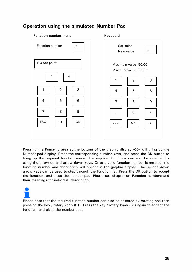
Operation using the simulated Number Pad Function number menu Keyboard Pressing the Funct-no area at the bottom of the graphic display (60) will bring up the Number pad display. Press the corresponding number keys, and press the OK button to bring up the required function menu. The required functions can also be selected by using the arrow up and arrow down keys. Once a valid function number is entered, the function number and description will appear in the graphic display. The up and down arrow keys can be used to step through the function list. Press the OK button to accept the function, and close the number pad. Please see chapter on Function numbers and their meanings for individual description.
Please note that the required function number can also be selected by rotating and then pressing the key / rotary knob (61). Press the key / rotary knob (61) again to accept the function, and close the number pad.
1 2 3
4 5 6
7 8 9
ESC 0 OK
^ v
F 0 Set-point
0 Function number Set-point
New value_
Maximum value 50.00
Minimum value -20.00
1 2 3
4 5 6
7 8 9
. 0 -
ESC OK <-
26
Main menu The following functions are available: Compact menu Comfort menu Control parameters Acoustic alarm Comfort menu Auto-Start Display modes Clock Enter program ComG@te (with connected ComG@te only) Overtemperature protection Compact menu Pump settings Compressor automatic (not valid for all units) Set-point Control parameters Set-point limits Display functions Start & stop Display modes Start ramp E-grade packages Temperature control mode Enter program User menu - select Factory default Exit Language Limits Overtemperature protection (for units with heating) Program start&stop Protection functions Pump settings Sensor adjustment Service Set-point Set-point limits Settings (others) Software version Start & stop Start ramp Temperature control mode Temperature scale Time scale User menu - config. User menu - select 2nd set-point WebG@te (with connected WebG@te only) Exit The individual functions are described in the following pages:

27
Compact Menu The functions used frequently are clearly listed in the compact menu. Display modes Following functions are available:
1. Standard: Values are displayed numerically (valid for all temperature control devices with Unistat Pilot and CC-Pilot).
2. Graphic: Internal temperature, process temperature and set-point are displayed graphically – valid for Unistat Pilot. (with CC-Pilot only possible with Exclusive or Professional upgrade package).
3. Device message: please see following example (valid for all temperature control devices with Unistat Pilot and CC-Pilot).
4. Status Interface: Information on switch condition of e.g. ECS and PoCo / ALARM (valid for all temperature control devices with Unistat Pilot and CC-Pilot).
5. Large display: Values are displayed in large numerical format (valid for all temperature control devices with Unistat Pilot and CC-Pilot).
6. Summary 1: Service information (valid for all temperature control devices with Unistat Pilot and CC-Pilot).
7. Return to main menu Display modes is used to select the required display or information window (e.g. ComG@te status or Device message). The standard setting is Graphic. Example: Display on choosing Device message. By turning the rotary knob / key (61) one can display the individual messages. Take note of the message counter for reference.
Message in clear text
Date / Time of the Message
10.04.06 3/100 17:11:39 Message-ID: -16427 Servicepassword was given Actual status: 0x000F Pump running compressor stopped Heating on Manual set-point active 2nd set-point not active Mains frequency. 50Hz detected 230V AC 1 Phase Extended Status: 0x000D Compressor on Fan on Power isolation relays activated
Status information in clear text.
Status information in clear text.
Message - counter
Message - number
Info: present Status
Info: extended Status

28
Example: Indication when choosing Large display Comfort menu Here one can switch to the whole range of functions. Please also note the chapter on Comfort menu, where further functions of the comfort menu are described. Enter program This corresponds to Function F20 in the Funct.-no. menu. Here it is possible to write new programs, or programs already written can be edited and changed or erased. (add segments, insert segments, delete segments or edit segments) or erase whole programs. Also one can set a particular behaviour at the end of the program through Stop temp. control, Continue temperature control (temperature is continued at the last set-point) or Repeat (the temperature program is restarted). One can also display the program elements as text or graphic. Working with the program creator will be described below. Start ramp Corresponds to Function F19 in the Funct. No. menu. This ramps the temperature set-point up or down as required, instead of a sudden temperature jump. It can be used in both internal and process control modes, to ramp the temperature at the internal or external temperature sensor (see function F3). Note: A ramp can be started only if temperature control has previously been activated.
TInternal °C -20.5
TProcess °C -20.1
Tset-point °C -20.0
OT 35 °C
Temperature control is active

29
Program creator
Segment 1 Seg.: 1 2 3 4 5 SP: 20,00°C Time/min: 1 Mode: internal Stability: Temp AIF OUT: off AIF%:0 Funct.: linear Tconst./ min 0 PoCo: off
Segment 1 Seg.: 1 2 3 4 5 SP: 20,00°C Time/min: 1 Mode: internal Stability: Temp AIF OUT: off AIF%:0 Funct.: linear Tconst./ min 0 PoCo: off
Save
DEL INS BACK
COMPACT MENU: . . Enter program . .
Select Program: Program 1 . Program 10 Return to main menu Program 01 contains 00 segments
SELECT ITEM: Segments Segments (List) End condition Input program name Delete program Return
Please enter
Crystalisation
1 2 3 4 5 6 7 8 9 0 q w e r t z u i o p ü a s d f g h j k l l ö ä y x c n m
AT PROGRAM-END: Stop temperature control Continue tmp. control Repeat Return

30
To create a new program, continue as follows:
1. Select the menu point Enter program from the Compact / Comfort menu. 2. Select the program number to be used. Information on the number of segments
from the program currently used etc is shown in the lower part of the graphic display screen (60).
3. After selecting the program, more functions are displayed. Begin by selecting the segment option from the sub menu point. Confirm by pressing the rotary knob / key (61). The cursor (frame) points first to the set-point. Choose and modify each individual function (segment time, temperature control mode,…) by turning the rotary knob / key (61). Press the rotary knob / key (61) to confirm your selection. By means of the function (soft-key) “DEL”, “INS” and “BACK” segments may be inserted easily and deleted. After having pressed the key “INS” select a segment no. by turning the rotary knob / key (61). This segment no. can be added as a new segment. Values can be modified by turning the rotary knob / key (61). Please note, that when selecting an exponential ramp function (E-grade Professional) the end value (more precisely 99% of the end value) will be reached after 5 times the time constant has elapsed. After having made all inputs confirm by pressing the rotary knob / key (61) and save the segment.
4. Via the sub menu point End condition, available options for the end of the program (e.g. Stop temperature control, or Continue temperature control) can be chosen.
5. A new program name can be entered from the menu point Input program name by means of the keys from the touch screen (60).
6. To delete a program, use the Delete program option from the sub menu and confirm the program to be deleted.
7. After entering a program, the Program start & stop option from the main menu can be used to call up, run and stop it. An early stop to the program can also be achieved by selecting the main menu point Program start & stop.

31
Control parameters
Select auto./ manual Automatic control parameters
CONTROL PARAMETERS: Select auto./ manual Config. automatic Config. manual param. Reset control parameters Display parameter Return to main menu
AUTOMATIC CONFIGURATION: Find control parameters Control dynamics Display control parameters Fluid properties Go back
Param. Control and detection KPInt. 181.3 TtInt. 1.4 TNInt. 77.6 TIInt. 7033.2 TVInt. 0.0 VUmw. 0.00 .
CONTROL DYNAMICS: Fast, small OS Without overshoot Go back
SELECT THERMAL FLUID: No specification M120.08.02 M90.200.02 (DW-Therm) M90.055.03 (Sil. oil) M40.165.10 (Sil.oil)
SHOW FLUID: Thermal fluid: M90 Min. working temperature: [°C]: -90 Characteristics: (zero)
TEMPERATURE CONTROL MODE: Internal Process (Cascade) Set-point tracking Go back
CONFIGURATION MANUAL CONTROL PARAMETERS: Change control parameters Display control parameters Go back
AUTOMATIC / MANUAL SELECTION: Manual control parameters Automatic control parameters Go back
BYPASS: If there is a partial short cut through a bypass, please choose “yes”.
AUTOMATIC MODE: Fast identification Estimate control parameters Go back
THERMAL FLUID: Thermal fluid Circulation volume Bypass usage Show fluid Go back
FILLING QUANTITY: Please enter the approx. thermal fluid filling capacity without the of the expansions vessel. …
Temperature set-point Act. Setting: 20.00 Temp. max 35.00 Act. Temp. 2.00

32
After selecting the main menu point Control parameters, the following functions are available:
• Select autom./manual • Config. automatic • Config. manual parameters • Reset control parameters • Display parameters • Go back
Select Autom. / Manual (Select Automatic / Manual) Application of the automatically detected or manually entered parameters, in order to regulate the temperature. We recommend the setting: Automatic control parameters! Config. Automatic (Automatic configuration) The following functions are available:
• Find control parameters • Control dynamics • Display control parameters • Fluid properties • Go back
Find control parameters
Two options of controller parameterisation are available:
1. Fast identification (not available with CC-Basic software) 2. Estimate control parameters
To 1. Fast identification: Delivers a relatively fast and reliable control parameter with which a rapid regulation with a relatively high constancy can be reached. First, start temperature control and run for some minutes to achieve a suitable stable set-point. During the following do not carry out any changes on the system (e.g. filling / emptying the reactor core, change of agitator speed, change of the process sensor position etc.). After activating this function, a table with thermal fluids is displayed. Select the appropriate thermal fluid here. If your thermal fluid is not listed in the table, please select no specification. If your thermal fluid is not listed, the controller assumes a thermal fluid with characteristics, which normally results in an overshoot-free (slower) control. After selecting the thermal fluid, you are asked, whether you want to identify and control Internal or Process (cascade or set-point tracking). You are then requested to enter a set-point. Please note, that the identification is only successful, if the new set-point differs from the current set-point by at least 10 K. In the status field of the chart display (60), the information Temp. + Ident. active is displayed.
33
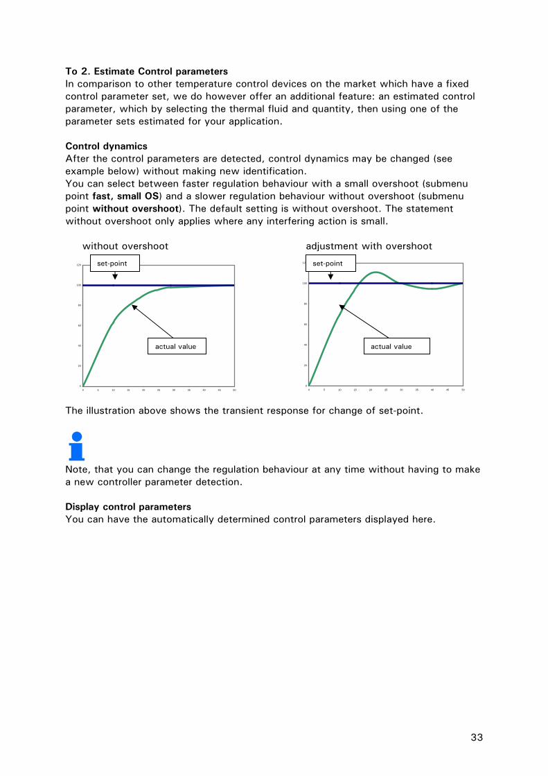
To 2. Estimate Control parameters In comparison to other temperature control devices on the market which have a fixed control parameter set, we do however offer an additional feature: an estimated control parameter, which by selecting the thermal fluid and quantity, then using one of the parameter sets estimated for your application. Control dynamics After the control parameters are detected, control dynamics may be changed (see example below) without making new identification. You can select between faster regulation behaviour with a small overshoot (submenu point fast, small OS) and a slower regulation behaviour without overshoot (submenu point without overshoot). The default setting is without overshoot. The statement without overshoot only applies where any interfering action is small. without overshoot adjustment with overshoot
0
20
40
60
80
100
120
0 5 10 15 20 25 30 35 40 45 50
0
20
40
60
80
100
120
0 5 10 15 20 25 30 35 40 45 50
The illustration above shows the transient response for change of set-point.
Note, that you can change the regulation behaviour at any time without having to make a new controller parameter detection. Display control parameters You can have the automatically determined control parameters displayed here.
set-point set-point
actual value actual value

34
Set-point This corresponds to Function F0 in the Funct. no. menu. The set-point is limited to the band between the upper and lower set-point limits. The following is true: minimum set-point <= set-point <= maximum set-point Set-point limits This corresponds to Function F1 and F2 in the Funct. no. menu. It allows the operating set-point range to be set between user-determined minimum and maximum temperatures. Start & stop Operating modes (temperature control, air-purge, circulation…) can be selected and activated / deactivated. Temperature control mode Following options are available: 1. Internal, corresponds to outlet temperature, jacket temperature control 2. Process (cascade, corresponds to e.g. external reactor temperature control) 3. Set-point tracking (the sensor value is used as set-point) Over-temperature protection Cut-off limits can be set in the heating chamber / heating. Please note chapter on setting the Overtemperature protection (OT). User menu - select Under this point, one can choose which user menu (previously configured via User menu-config under the main menu point) should be used. Only this menu, with its approved points then will be seen.
35
Comfort menu Display functions Following functions are available: 1. The brightness of over-temp. and temperature 7-segment displays can be adjusted here. 2. Warnings (manual confirmation or automatic confirmation) 3. Messages (manual confirmation or automatic confirmation) 4. Inactive menu items (display / unmask inactive menu items) 5. Temperature resolution (0.01 °C, 0.1 °C) 6. Brightness TFT backlight 7. Go back Display modes A description on this menu point can be find in the chapter Compact menu. Acoustic alarm Here you have the option to activate / deactivate the acoustic signal output. Auto-Start (after power on) This corresponds to Function F5 in the Funct.-no. menu. This allows the start-up condition, after mains failure to be defined. The following is true: Auto-Start function = OFF / Standby Temperature control will not be restarted when power restored (Default setting) Auto-Start function= ON / Temp. control active. After power loss – Temperature control will be restarted on return of power.
Caution! The end-user should assess the risk and consequences of this setting for their application. The default setting is OFF. Limits The following functions are available:
1. Delta T limit (limitation of the jacket temperature to the reactor temperature) 2. Maximum heating power (limitation of the heating power in % steps) 3. Maximum cooling power (limitation of the cooling power in % steps) 4. Go back
You can here set the maximum allowable difference (Delta T limits) between the internal temperature (jacket temperature) and the process temperature when using process control. If the chosen temperature difference is reached, then the temperature control device power is reduced so that this temperature difference is held. This function can protect the application (e.g. glass reactor) against thermal stress caused by too high a Delta T.

36
Settings (others) Here, information concerning your application may be entered or read out. The values input here will be considered when controller parameterisation is taking place (please see chapter on Control parameters) The following functions are available under the menu point Change thermal fluid:
1. Thermal fluid (choose thermal fluid) 2. Circulation volume (indication on volume to be temperature controlled) 3. Bypass usage 4. Show fluid (values and information on thermal fluid are being displayed) 5. Back
Under the menu point Bath selection different bath volumes can be chosen. Please select accordingly. Sensor adjustment
There exists a possibility to carry out an adjustment of the internal sensor, the process sensor and the return sensor. We recommend to consult our service department before carrying out any adjustments of the internal sensor and return sensor. An adjustment is only necessary, if due to ageing of sensors measuring is inaccurate or insufficient. There are different reasons for inaccuracy of the process sensor, e.g. non-linearity, contact resistance. The new generation thermoregulation units give you the opportunity to carry out different adjustments. If the inaccuracy applies over the whole temperature range, adjustment should be carried out only at one point (offset adjustment). If accuracy is not constant over whole temperature range we recommend an adjustment of up to 5 spots. The more spots are included the better are the measuring results afterwards. For adjustments you will need a reference thermometer with corresponding accuracy. The sensor of the thermometer has to be positioned as close as possible to the process sensor. Settings for the process sensor Start thermo control and enter a set-point, which serves as first adjustment point. After set-point is reached, wait until the temperature is constant. Choose the menu point Sensor adjustment / Adjust process sensor / New adjustment point from the comfort menu. Enter the temperature measured by the process sensor into the first input field. This value has to be acknowledged via the OK-key. Enter the actual temperature measured via reference thermometer into the second input field. Confirm this value as well. Sensor adjustment at this temperature point is then completed. Optionally you can then fix a new set-point used for second adjustment point. After set-point is reached you may continue as described above (adjustment at the first adjustment point). To define additional adjustment points, continue in a similar manner.

37
Compact menu Here one can switch to the limited possibilities of the compact menu. Compressor Automatic Corresponds to Function F35 in the Funct.-no. menu. This is used to select the operating mode of the compressor. The default setting is always on. Automatic: The compressor control is set to switch on and off as required by the unit. Benefit: Energy saving Disadvantage: Longer response times to sudden increase in cooling demand. Always on: The compressor is always running, so the refrigeration machine is always immediately available. Always off: The compressor is always off.
Compressor Automatic has to be switched to always on when setting process safety in the main menu point over-temperature protection / OT Mode (only valid for units with compressors). Enter program This corresponds to Function F20 in the Funct.-no. menu. Here it is possible to write new programs, or programs already written can be edited and changed or erased. (add segments, insert segments, delete segments or edit segments) or erase whole programs Also one can set a particular behaviour at the end of the program through Stop temp. control, Continue temperature control (temperature is continued at the last set-point) or Repeat (the temperature program is restarted). One can also display the program elements as text or graphic. Program start & stop Corresponds to Function F22 (Program control) in the Funct.-no. menu. This enables the temperature control program to be paused at the current set-point and to continue the program by pressing Program continue, to leave the current segment and proceeding to the next one by pressing Go to next segment and to leave the program by pressing Stop program. Pump settings Settings of speed (valid for VPC-Models) and pressure (valid for Petite Fleur). Start ramp A description on this point can be found in the chapter on Compact menu.
38
Control parameters A description on this point can be found in the chapter on Compact menu. Protection functions Following functions are available: 1. Internal sensor high limit alarm 2. Internal sensor low limit alarm 3. Process sensor high limit alarm 4. Process sensor low limit alarm 5. Warning time level (only valid for immersion thermostat CC-E and combinations using the immersion thermostat CC-E) 6. Go back Int. high lim. alarm: (Internal sensor high limit alarm) Corresponds to the Function F108 in the Function-no. menu. The temperature monitoring is first activated when the internal (or process) temperature is below the maximum temperature limit. The temperature must “dip” into the limit band by 3 K, before an alarm will be triggered. If the temperature limits are below room temperature, the unit temperature must first reach the temperature band before the monitoring is activated. This method allows the monitoring temperature to be easily checked and changed. An alarm is displayed if the temperature value set here is exceeded for more than 3 seconds. NOTE: The default setting is set to a value that lies few degrees above the upper temperature limit of the machine. Int. low lim. alarm (Internal sensor low limit alarm) Corresponds to the Function F109 in the Function-no. menu. An alarm is given when the measured temperature is lower than the set limit values for more than 3 seconds. NOTE: The default setting is set to a value that lies few degrees below the lower temperature limit of the machine. Proc. high lim. alarm (Process sensor high limit alarm) Corresponds to the Function nr. F106 in the function menu. An alarm is displayed if the temperature value set here is exceeded for more than 3 seconds. NOTE: The default setting is set to a value that lies few degrees above the upper temperature limit of the machine. Proc. low lim. alarm (Process sensor low limit alarm) Corresponds to the Function nr. F107 in the function menu. An alarm is given when the measured temperature is lower than the set limit values for more than 3 seconds. NOTE: The default setting is set to a value that lies few degrees below the lower temperature limit of the machine.

39
Warning time level As low-level protection you can enter a warning time until the actual switching off of the temperature control unit. In case of low-level, a signal will be sent out (you therefore have to set the signal to ON in the main menu point Acoustic alarm). Level indication will be displayed in red. A switch off, however, will take place after the warning time has elapsed. This function allows you to refill thermal fluid before it comes to a switch off due to low fluid level. Service This menu is only available in service mode, and may only be accessed after contacting Huber. It allows the unit’s internal sensors and other data to be directly read, for service purposes. Software version Corresponds to Function F98 in the Function-no. menu. The installed software version of the electronics are displayed. Set-point A description on this menu point can be found in the chapter on the Compact menu. Set-point limits A description on this menu point can be found in the chapter on Compact menu. Language This corresponds to Function F90 in the Funct. No. menu, and allows the unit’s operating language to be selected. The language options displayed are available. Start & stop A description on this menu point can be found in the chapter on Compact menu. Temperature scale It is possible to choose between °C, °F and K Temperature control mode A description on this menu point can be found in the chapter on Compact menu. Over-temperature protection A description on this menu point can be found in the chapter on Compact menu.
petite fleur
Serial Number: 77507 LoadCode: 803261629 Create Conde : 708020946 CC-Pilot: V06.10.001 Jan 12 2010 16:38:15 Serial Number : 36 Control: V05.10.001 1201 Jan 12 2010 16:38:15 Serial Number : 747
Continue: Press Enconder button

40
Clock Sets the unit Time and date. A number of functions can be chosen, e.g. a calendar / reminder function and timed start can also be configured. Example: Set alarm clock First enter the temperature programme via the main menu point clock / alarm clock function / acoustic signal. The acoustic signal will be given out when the time (date) is set via the function clock / action alarm clock / set alarm clock. User menu - select A description on this menu point can be found in the chapter on Compact menu. User menu - config. A description on this menu point can be found in the chapter on Compact menu.
CLOCK FUNCTIONS: Set time Set date Autom. summer time Set alarm clock Alarm clock function Return to main menu Date : 13.05.08 Time: 09:39:30 Alarm clock date: 18.05.00 Alarm clock time: 04:30:00 Action: Program 1 Start
FUNCTION ALARM CLOCK: No function Acoustic signal Program start Set alarm clock Return to main menu

41
Factory default This section allows the different areas of the temperature control unit to be reset to the factory default. This can be a relatively quick way of changing the unit settings. Unit control data: Resets the set-points, set-point limits, temperature control mode, to the factory-set default values. Settings in the user menu and programs created using the programmer remain unchanged. User menus: Resets the complete user menus to their default settings. Settings in the unit data and programs created using the programmer remain unchanged. Programmer: Resets complete programs to default settings. Settings in the unit data and user menus remain unchanged. All together: Resets the unit data, user menu, program, and controller parameters to default values. Time scale The time display can be displayed in various formats (hh, min, sec). 2nd set-point Corresponds to the Function F4 in the Function-no. menu. The input of a 2nd or alternative set-point is done in the same way as the normal set-point under the menu point set-point. This second set-point is activated with an external control signal (Function F28) or through a watchdog event

42
ComG@te menu Here, the functions (analogue interface, ECS-Standby, PoCo Alarm and digital interface) used in connection with an external control (e.g process control system “PCS”) are listed. Analogue Interface
ANALOGUE-INTERFACE: Config. input Config. output Go back
ANALOGUE INPUT:AIF–Input - Function On cable break Config. input/output Adjustment On analogue error Display AIF value Reset AIF input Show table values Current / voltage switch Filter constant Go back
AIF INPUT FUNCTION: AIF ->Input off AIF ->Internal temp. AIF ->Process Temp. AIF ->Set-point AIF ->Heating 0-100% AIF ->Power AIF ->Pump speed setp. AIF ->Pump press. setp. Go back
ADJUST: Adj. current value Enter in table Go back
Adjustment of the current measured value by input of the reference value
ON CABLE BREAK: Trigger an alarm No alarm, normal operation Go back
ON ANALOGUE ERROR: Switch off Act. 2nd Set-point Go back
ANALOGUE INPUT: Means: AIF -> Input off Action on analogue error: Switch off Action on cable break: Trigger an alarm Configuration In/Out 4.00mA -> 274.0 °C 20.00mA -> 274.0 °C Actual AIF input values: 0 Bit -> 0.00mA->0.00 °C Continue: Press Encoder button
CONFIG. INPUT/OUTPUT Temperature T1 Temperature T2 Go back
SHOW TABLE VALUES: TemperatureT1 Temperature T2 Go back
CURRENT / VOLTAGE SWITCH: Current Voltage Go back
WARNING: Following Parameters are going to be removed when resetting the analogue interface Measurement range Adjustment In / output function
AIF FILTER CONST: Act. Setting: 0002 Max. Setting 0010 Min. Setting 0000 New setting 0002

43
Using the analogue interface, the unit can be controlled via an analogue (0/4-20 mA or 0-10V) signal. An analogue (0/4-20 mA or 0-10V) output signal is also available. The schematic above describes the structure of the analogue input and output. Via the filter constant in the menu point analogue input it is possible to smooth a noisy input signal. Below is an example using the analogue input to provide a set-point, and the analogue output gives the process temperature. The current / temperature configuration is also shown. E.g. required operating temperature range is 0°C to 100°C. 0°C should correspond to 4mA. 100°C to 20mA. The 4…20mA (I / O) is available on the analogue interface connector. An alarm should be given when the cable breaks. The unit should be switched off if there is an analogue error.
ANALOGUE-INTERFACE: Config. input Config. output Go back
ANALOGUE OUTPUT: AIF-Output - Function Config. input/output Adjustment Reset AIF output Show table values Go back
SOURCE ANALOGUE OUT: No output Set-point Internal temp. Process temp. Manual preset Programmer RS232 / 485 Pump Press. act. Go back
CFG. OUTPUT RANGE Current at T1 Current at T2 Go back
ADJUSTMENT: Adj. current value Enter in table Go back
Adjustment of the current measured value by input of the reference value
WARNING: Following Parameters are going to be removed when resetting the analogue interface Measurement range Adjustment In / Output function
SHOW TABLE VALUES: TemperatureT1 Temperature T2 Go back

44
Settings:
1. Settings on temperature / current range Select analogue interface / config. input / adjust measurement range Enter the temperature range to correspond to 0/4-20mA (T1=0 °C, T2=100 °C).
2. Select input signal Select the input signal (AIF-> set-point) via analogue interface / config. input / AIF-Input - Function
3. Select output signal Select the output signal (Process temp.) via analogue interface / config. output / output range
4. Select action if cable breaks Select analogue interface / config. input / on cable break Trigger an alarm.
5. Select action upon analogue error Select analogue interface / config. input / on analogue error Switch off.
6. The settings can be reviewed by selecting: analogue interface / config. input / display AIF values.
Please note that the fine signal adjustment functions the same for the analogue output as it does for the input. Setting information for fine adjustment. General: When the machine is delivered and after a Reset (Reset AIF input) the interface will be set accurately enough. An adjustment is not necessarily required. It is possible at any time to adjust the precision of the input channel. This could be required if the set-point input current does not coincide with the expected temperature value. If as shown in point 1 above, an input of 4.000mA does not give exactly 0°C, but maybe 1°C. A fine adjustment can then be made. Change to menu point analogue interface / config. input / fine adjust / xxxxx. Feed 4.000mA into the interface. Confirm the value. Choose then analogue interface / config. input / fine adjust / xxxxx. Feed then 20.000mA into the interface. Confirm the value. At the end, a current input of exactly 4.000mA should give a set-point of 0°C and a current input of 20.000mA should give a set-point of 100°C. The fine adjustment of the output channel is done in a similar manner. A sensor value of 0°C and 100°C should give an output current value of 4.000mA and 20.000mA.

45
Digital Interface Following functions are available:
1. Select RS232/485 (option between RS232 and RS485) 2. Baudrate (selection of transmission speed) 3. Slave address (Selecting a bus address, only when using RS485) 4. Test dig. Interface (command TI is send via RS232) 5. Go back
ECS / Standby External control signal Corresponds to Function F28 in the Funct.-no. menu. This is a potential free input. A closed contact switches e.g. temperature control on, and an open contact switches e.g. temperature control off. Please also refer to the ComG@te section of this manual. Following functions are available:
1. No action 2. Switch to 2nd set-point 3. 2nd set-point selective 4. Internal / Process 5. Temperature control ON / OFF 6. Release
* No action: A switch of the contacts open / closed or closed / open has no effect. * Switch to 2nd set-point Switching the closed contact to open contact causes the unit to use the value of the second set point. A further switch from open to closed contact causes the unit to continue temperature control at the second set point. * 2nd set-point selective An open contact causes the unit to use its internal set point. A closed contact causes the unit to use the value of the second set point. * Internal / Process A closed contact causes the unit to immediately switch e.g. between internal and external control mode. An open contact causes the unit to switch back to its original control mode.
* Temperature control ON / OFF Switching from open to closed contact causes the unit to start temperature control. Switching from closed to open contact causes the unit to stop temperature control. * Release Switching from closed to open contact while temperature control is operating causes the unit to stop temperature control. Switching back from open to closed contact does not start the unit.

46
PoCo alarm Pot. free Contact (PoCo) Corresponds to Functions F6, F7, and F8. This function allows a relay contact, in the ComG@te (46) to be controlled and activated. Please also review the ComG@te section of the manual.
The following functions are available: OFF: The PoCo displays the OK status when the unit is ready to operate. This condition is after the internal controller check, approx. 30 sec. after the switch on. The OK status will be ended by switching off the mains or a fault. Check act. value.: The relay switches when the current internal temperature is outside the range set between the PoCo minimum and maximum internal temperatures (F6 and F7). The values in functions F6 and F7 are relative to the current set-point. If the range is exceeded the potential free contact is switched (from the OK status), and the unit will continue to operate. If the actual value is in the range, the contact will be reset to the OK status. External alarm: The PoCo relay is only activated if the unit is in “fault status” when it is switched on. This is so that the alarm is not raised when the unit gets switched off. If you wish the alarm function together with the work flow principle, please use the PoCo function OFF. Unipump / PCS: (Unipump / Process Control System) This PoCo function is used to connect the signal calling for the circulation pump to start with an external booster pump. This has to be done so that the external pump runs in synchronisation with the circulation pump in the unit, this means that the PoCo activates (to the OK status) as soon as the circulation pump starts. PCS: An example of this would be when temperature control would be controlled by a “PCS" via the external control signal (Menu point External control signal or Function F28), the PoCo can be used to communicate. Condition PoCo ON means temperature control is activated. Condition PoCo OFF means temperature control is not activated. Control by RS232: The relay is controlled via an RS232 command. Therefore please note our Huber-Software. Check process temperature.: A measured temperature check for the PROCESS SENSOR providing it is not the control sensor. The PoCo relay switches when the current external, (process temperature) is outside the range set between the PoCo minimum and maximum external temperatures. When the unit is set to internal control, and the PoCo check process temperature” is selected, the temperature of the external sensor is monitored – this sensor can be independent of the internal temperature and the temperature control process. The limits set by F6 and F7 still apply.
47
Unipump with echo: This function is used to monitor if the Unipump being controlled by the PoCo is operating in synchronisation with the Unistat’s own pump. The operating status of the Unipump can be signalled via a normally open contact by connecting to a “level” connector. If the Unipump does not operate with the machine, a fault signal will be generated. This operating mode is very useful if the Unipump has to be monitored, either to guarantee the desired temperature control or to avoid unintended heating of the thermal fluid. Programmer: The relay is controlled by a command from a segment within a temperature profile running on the programmer. Please also note the menu point on Enter program. Check int. temp. abs. (check internal temperature absolute) The relay switches when the current internal temperature is outside the specific band determined by the maximum and minimum temperature limits. Outside this band PoCo is active, within the band PoCo is inactive. Check proc. temp. abs. (check process temperature absolute) The relay switches when the current external temperature is outside the specific band determined by the maximum and minimum temperatures. Outside this band PoCo is active, within the band PoCo is inactive.

48
Function Numbers and their meaning
A detailed description of the functions, as well as an alternate operation for the menu guide can be found in the chapter Compact-/ Comfort-/ ComG@te menu F0 Set-point minimum set-point <= set-point <= maximum set-point If an attempt is made to enter a set-point outside these limits, then a warning message will be shown on the display (60) and the set-point will not be accepted. F1 Minimum set-point, F2 Maximum set-point The range for the set-point limits should conform to the safety data sheet of the thermal fluid being used and the working temperature range allowed by the administrator. F3 Temperature control mode Internal temperature control or process temperature control. F4 2nd set-point Alternate set-point which is being entered after activation. Please also note the setting of function F28 (External control signal). F5 Auto-Start Auto-Start function= ON / Temp. control active. After power loss – Temperature control will be restarted on return of power. Auto-Start function = OFF / Standby Temperature control will not be restarted when power restored (Default setting)
Caution! The end-user should assess the risk and consequences of this setting for their application. Default setting is OFF. F6 PoCo maximum limit (Pot. free Contact Maximum temperature) Used in conjunction with function F8. This function sets the upper limit (Delta T) relative to the set-point. F7 PoCo minimum limit (Pot. free Contact Minimum temperature) Used in conjunction with function F8. This function sets the lower limit (Delta T) relative to the set-point.
49
F8 PoCo - programming The options for the potential free contact are given and described in the earlier Potential free Contact section the ComG@te menu of this manual (Pot. free Contact). F9 Control parameters Please see chapter Control parameters in the Compact menu for detailed description. F10 Machine messages Information on the machine about condition (status, warnings and faults). F12 Adj. internal sensor (Adjust internal sensor) Up to 5 free selectable temperature values for the adjustment of the internal sensor can be defined and adjustment may be carried out. Please also see description on Sensor adjustment in the chapter Comfort menu. F13 Adj. process. sensor (Adjust process sensor) Up to 5 free selectable temperature values for the adjustment of the process sensor can be defined and adjustment may be carried out. Please also see description on Sensor adjustment in the chapter Comfort menu. F14 Adj. return sensor (Adjust return sensor) Up to 5 free selectable temperature values for the adjustment of the return sensor can be defined and adjustment may be carried out. Please also see description on Sensor adjustment in the chapter Comfort menu. F18 Delta T limit Maximal admissible temperature difference between internal and process temperature. Once the maximum temperature difference has been reached, the unit will automatically reduce its cooling (or heating) capacity as required. F19 Ramp function The set-point default refers to, depending on the temperature control mode set (function F3) the internal sensor or process sensor. F20 Enter program You can enter the chosen temperature programme. F22 Program control Choose between following options: Start, Stop, Break, Skip to the end segment of a running temperature programme. F23 Program start Start of the temperature programme (calendar start). F27 Time scale Time scale in minutes or hours. F28 Ext. control signal (External control signal) The external control signal can be used to control one of a number of available unit functions. Please see chapter on ComG@te menu.

50
F30 Set date Setting the date. F31 Set time Setting the time. F33 Set over-temperature protection Setting the over-temperature protection. Please note chapter on setting the over-temperature switch. F34 Air purge Start / Stop air purge F35 Compressor automatic This is used to select the operation of the compressor: Default setting is always ON Automatic: The compressor automatic is set to switch on and off as required by the unit. Benefit: Energy saving Disadvantage: Longer response times to sudden increase in cooling demand. Always ON: The compressor is always running, so the refrigeration system is always immediately available. Always OFF: The compressor is always off.
The compressor automatic (valid for units with compressors only) must be set to always on when selecting process security in the main menu Over-temperature protection / OT Mode F37 Temperature mode Setting the temperature mode. F39 Signal Activating the signal. F40 Test RS232 Start / Stop F41 Select user menu Please refer to chapter select user menu. F42 Configure user menu Please refer to chapter configure user menu. F46 Define analogue input (function analogue input) This function allows an analogue input current of 0/4-20 mA or 0-10V to be assigned to an input value.

51
F47 On cable break This function determines the unit’s response to a break in the cable, e.g. turn off temperature control, or control to a second set-point. F49 Unit name This function displays the unit model number. F50 Input password Used only for Service. Contact Huber for further information. F52 Factory default This functions allows to reset the unit to the factory default. F55 Degassing mode Activating the degassing mode. Please see the section on Degassing an external closed application. F60 Information on the machine In this function information on the machine can be obtained. F61 X-Information (Service) Xxxxxxxxxxxxxxxxxxxxxxxxxxxxxxxxxxxxxxxxxxxxxxxxxxxxxxxxxxxxxxxxxx F68 Tempmove AIF – Tint Xxxxxxxxxxxxxxxxxxxxxxxxxxxxxxxxxxxxxxxxxxxxxxxxxxxxxxxxxxxxxxxxxx F69 Tempmove AIF Tproc Xxxxxxxxxxxxxxxxxxxxxxxxxxxxxxxxxxxxxxxxxxxxxxxxxxxxxxxxxxxxxxxxxx F70 Service increments May only be used under directions of our Customer Support Team. F71 Service functions Used only for Service. Contact Huber for further information. F72 Service temperature Used only for Service. Contact Huber for further information. F75 Cooling power man. One can here set a constant cooling power. An automatic cooling power adjustment does not take place. F84 Slave address Setting the unit´s BUS-address. F85 Baudrate Setting the Baudrate. F86 Select RS232 / 485 Choosing the interface.
52
F90 Language / Sprache Selecting the language. F98 Software version Display of software versions. F103 Set-points refrig. (Set-points refrigerating machine) Used only for Service. F106 Proc. high limit alarm (Upper alarm limit process temperature) A description of this function is given in the Safety Functions section of the Comfort menu. F107 Proc. low limit alarm. (Lower alarm limit process temperature) A description of this function is given in the Safety Functions section of the Comfort menu. F108 Int. high limit alarm (Upper alarm limit internal temperature) A description of this function is given in the Safety Functions section of the Comfort menu. F109 Int. low limit alarm (Lower alarm limit internal temperature) A description of this function is given in the Safety Functions section of the Comfort menu. F110 Circulation Starting circulation. F111 Air-purge Starting air purge. F112 Start / Stop thermo control Start / Stop thermo control. F124 Results current test (Service) Xxxxxxxxxxxxxxxxxxxxxxxxxxxxxxxxxxxxxxxxxxxxxxxxxxxxxxxxxxxxxxxxxxxxxxxx F125 Status ComG@te Information on activation of ComG@te signals. F126 Status sensors Display of sensor values. F128 Status cooling machine and pump Information on cooling machine and pump. F129 Status cooling control Information on cooling control. F130 Display mode graphic Choosing graphic display.

53
F131 Display mode normal Choosing standard display mode. F135 Adj. analogue input (analogue interface input current adjustment) Fine adjustment of the 0/4-20mA or 0-10V input current range. Using this function the current limits of the 0/4-20mA or 0-10V analogue input signal can be calibrated. See also chapter on the ComG@te. F136 Adj. analogue output (analogue interface output current adjustment) Fine adjustments of the 0/4-20 mA or 0-10V output current range. Using this function the current of the unit’s 0/4-20 mA or 0-10V analogue output signal can be calibrated, this is the current limits for your measured output or difference output via the AIF (see function F138). NOTE: Also see chapter on the ComG@te. F137 AIF input current / T Setting the current / temperature assignment for the A / D converter at the analogue input. F138 AIF-Output - Function Assignment of a temperature value to the output current. F180 Heat. power limit This function allows the available maximum heating power of the unit to be set between 0…100%. F181 Cool. power limit This function allows the available maximum cooling power of the unit to be set between 0…100%.

54
User menu – config. Using the configure menu function up to seven different operational modes can be set up. This is comparable to the main menu point Compact menu. However here the user menu can be stopped and edited at any time. There is also the ability for an administrator to create and save menu lists for individual users. Reducing the number of options in a list can give a clearer display and overview of the operation, as well increase security by locking out other functions.
Please note that the Configure user menu is password (code input) protected. For information on the enter code please contact our Customer Support Team. The path to select a user menu is given below:
Comfort Menu: . User meu – config. .
Please enter code
USER MENU – CONFIG.: User menu 1 User menu 2 User menu 3 User menu 4 User menu 5 User menu 6 User menu 7 Return to main menu
CONFIGURATION: User menu 1 Analogue interface + Display modes + Auto-Start + Limits + Digital interface + Real time clock + . . . . .

55
After entering the password, select one of the available user menus to enter the configuration program. After that you will enter the actual configuration program. A list of the comfort menu will be displayed. At the end of each of line there will be a “+” if that function is active. This can be changed to a “-“ using the control button / knob (61) to deactivate it.
User menu - select This option can be used to configure a user menu to be operated like a new main menu. In this case only the main menu points are accessible that have been previously activated through the main menu point “User menu – config.”.
Please note that the User menu configuration is password protected. The path to select a user menu is given below: After entering the correct password (please contact our customer support team), one of the available user menus can be selected. To return to using the full function, main menu, select the Administrator option from the user menu list.
COMF MENU: . . Config. User menu. .
Enter code
USER MENU - SELECT: Administrator User menu 1 User menu 2 User menu 3 User menu 4 User menu 5 User menu 6 User menu 7 Return to main menu
56
Chapter 3: Connect the machine, fill and prepare for the required application The following sections can be found in this chapter:
- Power connection - Transport protection (if applicable) - Start up - Connecting an external application 1. Closed application
1. Connecting an externally closed application (reactor) 2. Open application
1. Connecting an externally open application - Switching on the temperature control unit - Setting the Overtemperture switch - Setting set-point limits - Entering a set-point - Starting temperture control - Ending temperture control - Preparing an external application
1. Closed application 1. Filling an externally closed application 2. Air purging an externally closed application 3. Degasing an externally closed application
2. Open application 1. Filling an externally open application
- Draining an external application 1. Closed application 2. Open application
- Changing thermal fluid / internal cleaning
57
Power connection
. Danger! Check to make sure that the line voltage matches the supply voltage specified on the identification plate or data sheet. We disclaim all liability for damage caused by incorrect line voltages! Safety instructions
Transport protection The models 610, 610w, 615, 615w, 620w, 625w, 630, 630w, 635w, 910, 910w, 925w, 930w and 950 are provided with a transportation lock for the compressor. This lock must be released prior to the system's commissioning and re-fastened for the system's transport to a different installation site.
Danger! The four transport protection bolts of the compressor must be brought into the operating position before initial start-up of the temperature control device. - Releasing the transportation locks (operating position) Screw up the hexagon head screw (1) on the lower side of the housing using the socket wrench SW17 and tighten it against the weld nut (3). - Fastening the transportation locks (transport position) Unscrew the hexagon head screw (1) on the lower side of the housing using the socket wrench SW17 and tighten it against both the lock nuts.
Danger! Only connect the unit to a power socket with earthing contact (PE – protective earth)!
Caution! Do not move the unit from its location while it is running.
Danger! Never operate equipment with damaged mains power cables.
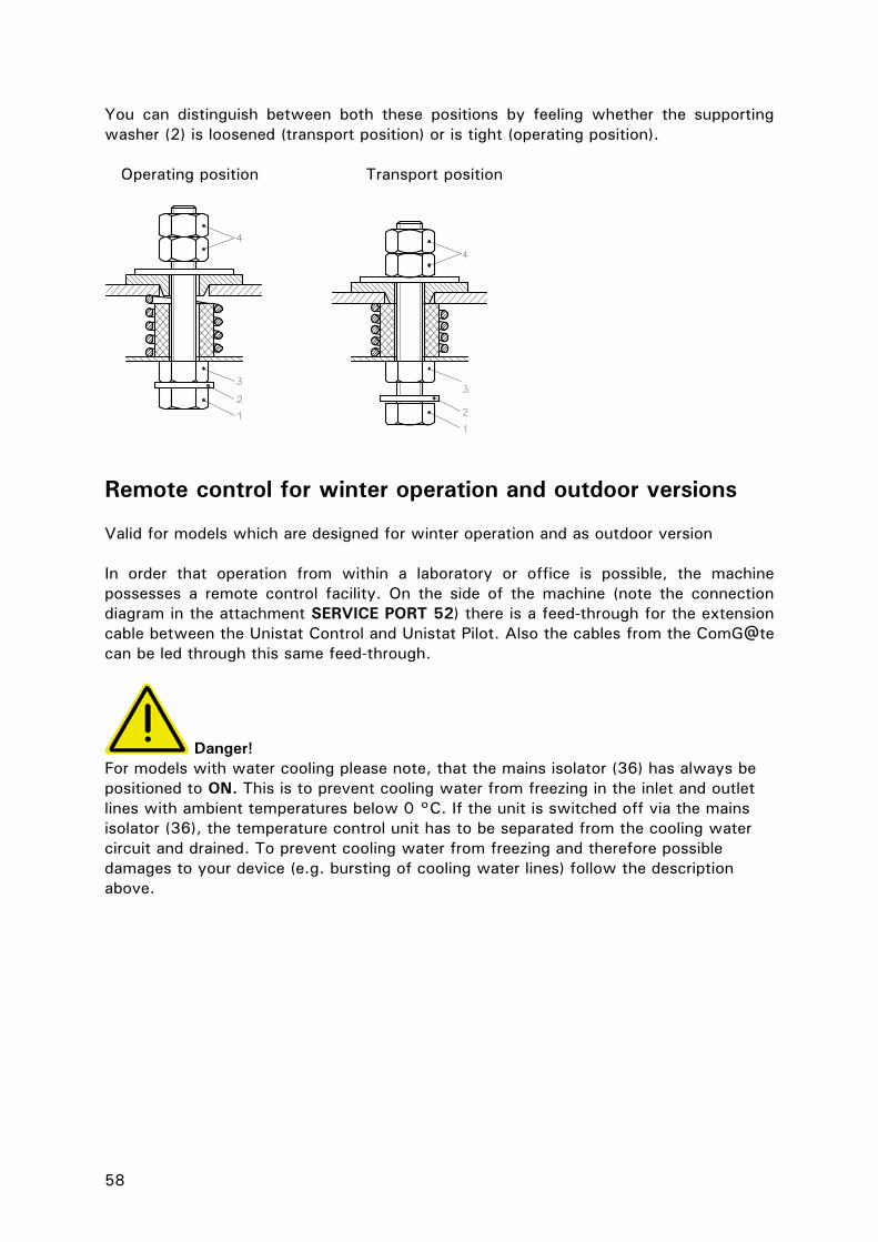
58
You can distinguish between both these positions by feeling whether the supporting washer (2) is loosened (transport position) or is tight (operating position). Operating position Transport position
Remote control for winter operation and outdoor versions Valid for models which are designed for winter operation and as outdoor version In order that operation from within a laboratory or office is possible, the machine possesses a remote control facility. On the side of the machine (note the connection diagram in the attachment SERVICE PORT 52) there is a feed-through for the extension cable between the Unistat Control and Unistat Pilot. Also the cables from the ComG@te can be led through this same feed-through.
Danger! For models with water cooling please note, that the mains isolator (36) has always be positioned to ON. This is to prevent cooling water from freezing in the inlet and outlet lines with ambient temperatures below 0 °C. If the unit is switched off via the mains isolator (36), the temperature control unit has to be separated from the cooling water circuit and drained. To prevent cooling water from freezing and therefore possible damages to your device (e.g. bursting of cooling water lines) follow the description above.

59
Start up
General All models must be moved and installed in an upright position. Provide for a stable installation and make sure that the thermostat cannot tilt. Ensure that sufficient fresh air is available for the circulation pump and compressors at the installation site. The warm exhaust air must be able to escape upwards unhindered. Observe the wrench sizes necessary for connecting the pump to the Unistat. The following table specifies the pump connections and the resulting wrench sizes as well as the rotor torque in Nm. Afterwards always check for leakage and if necessary retighten with the torque increased by 10% Device model Pump connection Wrench siez Wrench size Rotor torque Cap nut Connecting piece in Nm Tango Nuevo, Nuevo wl M24x1,5/M16x1 27/19 27/17 120/55Unistat 405, 405w, 410w M24x1,5/M16x1 27/19 27/17 120/55Unistat 705, 705w M24x1,5/M16x1 27/19 17 120/55Unistat 425, 425w M30x1,5 36 32 150Unistat 430, 430w M30x1,5 36 32 150Unistat 510w, 515w, 520w, 525w, 530w
M30x1,5 36 36 160
Unistat 610w, 615w M30x1,5 36 36 150Unistat 620w, 625w M30x1,5 36 36 150Unistat 630w, 635w, 640w, 645w, 650w,680w
M38x1,5 46 46 150
Unistat 815, 815w M30x1,5 36 36 150Unistat 825, 825w M30x1,5 36 36 150Unistat 905, 905w, 910, 910w, 912w, 915w M30x1,5 36 36 150Unistat 920w, 925w, 930w, 950 M38x1,5 46 46 200
Unistat 1005w M30x1,5 36 36 150Unistat 1015w M30x1,5 36 36 150 The table models tango nuevo (wl), unistat 405(w), unistat 705(w) are provided with M24x1.5 pump connections. Two adapters each equipped with M16x1 connections are included in the scope of supply for these models. After connecting the externally closed consumer, proceed as described in the Chapter Switching on temperature control unit
Table models The temperature control device can be retrofitted from 230V / 50Hz to 400V / 50Hz or vice versa. Only an electrical specialist may carry out the retrofitting. Install the device at the planned operation site. Please ensure that there is a 20 cm gap between wall and rear panel, even if you are operating a water cooled design. The maximum current consumption for 230V operation is slightly less than 16A. However, since there are 230V electricity networks with lower protection equipment, you will be requested during initial start-up to adapt the current consumption of your device to your electricity network. Apart from 16A current consumption, 13A and 10A are also selectable. If 13A or 10A have been selected, the heating performance of

60
1500 Watt (at 16A) is reduced to approximately 1100Watt (at 10A) as soon as the compressor starts up. The full heating performance is available again, as soon as the compressor has been turned off. This does not negatively affect the control behaviour. Under the main menu point Limitations, you can adjust your device to your electricity network at any time (if you want to change e.g. from a 230V / 10A electricity network to a 230V / 16A network).
Freestanding models Please infer the connection data from the data sheet. Install the tempering device at the planned operation site. Please ensure that there is a 70cm gap between wall and rear panel, even if you are operating a water cooled design.
Water-cooling
A cooling water controller is used in Huber tempering devices with water cooling, in order to reduce the cooling water consumption. This only allows as much cooling water to flow as is required by the current load situation of the temperature control device. If the required refrigerating capacity is low, only little cooling water is consumed. No cooling water flows in the OFF state. Only use pressure-resistant hoses in the cooling water circuit.
Caution! Depending upon mode of operation and available cooling water pressure, a cooling water pressure of > 2 bar can build up in the cooling water supply line. In order to avoid flooding of the premises, check the leak tightness and quality of the hoses, hose connections in regular intervals, and if necessary take appropriate measures (Replacement). Close down the cooling water supply to the temperature control device even during shorter shutdowns (e.g. over night). Reinforced hoses must be used for increased safety requirements.
Preparation of devices with water-cooling: Establish the hose connections for the cooling water. Please infer the position of the cooling water connections from the connection diagram in the appendix. Cooling water connectors Drainage with seal cap held closed and / or close. Open all stop valves. Please infer the minimum / maximum differential pressure in the cooling water circuit and the recommended cooling water inlet temperature from the data sheet.

61
Connecting an externally closed application (reactor) Remove the thread covers from the circulation flow (1) and circulation return (2). Make sure that the hose material is compatible with the thermal fluid and temperature range being used. The table for the appropriate size spanners can be taken from chapter Start up. In order that the application can be driven correctly, and that no air bubbles remain in the system, ensure that that the unit´s circulation flow (1) is attached to the lowest connection on the application, and the unit´s circulation return (2) is attached to the highest connection on the application.
2
1
1
2
1
2
1
2

62
Connecting an externally open (bath) application Remove the thread covers from the unit´s circulation flow (1) and circulation return (2). Make sure that the hose material is compatible with the thermal fluid and temperature range being used. The table for the appropriate size spanners can be taken from chapter Start up. In order that the application can be driven correctly, and that no air bubbles remain in the system, ensure that the unit´s circulation flow (1) is attached to the lowest connection on the application, and the unit´s circulation return (2) is attached to the highest connection on the application.
After connecting the external open application, please refer to the section on Switching on the temperature control unit.
1
2
2
1
1
2
1
2

63
Switching on the temperature control unit Switch on the unit using the mains switch (36). The unit performs initialisation tests, to check the full functionality of the thermoregulation unit. The control electronics first check the heaters, the sensors and then relays. If an error, or warning condition, arises, a message will be shown on the graphic display (60) giving details of the problem. For further information and assistance please contact our Customer Support Team.
Setting the over-temperature switch General Information The over-temperature switch is an independent function of the Unistat Control / CC-Pilot (with petite fleur) temperature control units. The software and hardware is configured so that essential functions and operations are tested during the self-test when the unit is first powered on. During these tests the sensor are tested for short- and open- circuits. If a problem arises then the unit is automatically prevented from operating until the problem is rectified. The constant monitoring of the outlet temperature provides safety for the connected application. It will be set immediately after having filled the unit with thermal fluid.
Warning! The over-temperature switch should be tested at least monthly, and after changing the thermal fluid. The over-temperature switch should be set at least 25K below the flame point of the thermal fluid. When using DW-Therm, in a closed system, please contact Huber for advice on the appropriate temperature range. Select the Overtemperature prot. option from the main menu. When received, the cut-off will be set to 35°C. If the temperature of the thermal fluid is higher then this when filled an alarm will be given after a short time. When this occurs follow the instructions below: Menu: After selecting an option then the display (60) will show the following message:
Over-temperature protection OT limit: heating OT Expansion vessel OT Mode Display all OT values Exit

64
Code for OT input xx xx is a number between 0 and 65000 that changes for each entry. The number is displayed for about 3 seconds. Please note this number to continue. To adjust the over-temperature switch, enter the number when requested. This procedure is to prevent the accidental adjustment of the over-temperature switch. After selecting Display all OT values the following information appears on the display (60): Over-temperature alarm
The temperature control unit and application should be constantly monitoring while carrying out the following procedures! Option 1: The over-temperature cut-off is below the flame point of the fluid (recommendation: -25K below), and the temperature advised by Huber for a closed application using DW-Therm. Adjust the over-temperature set-point higher so that the unit can be started. Enter a fluid set-point that is 25K below the flame point of the fluid. Start the temperature control. When the set-point 25K has been reached, adjust the over-temperature cut-off to 25K below the flame point. When using DW-Therm with a closed system, contact Huber for advice. Option 2: The over-temperature cut-off is at least 25K below the flame point of the thermal fluid, for DW-Therm in a closed system this is 200°C. Set the over-temperature cut-off to 25K below the flame point of the fluid. Contact Huber for advice when using DW-Therm in a closed system.
Warning! Do not forget to reset the over-temperature cut-off temperature!
Protection Overtemeprature Actual OT values Sensor heater 1 32.2 °C (Main heating) Sensor heater 2 34.0 °C (Fine heating) Sensor exp. v. 30.3 °C Setting OT ht. 1 35.00 °C Setting OT ht. 2 35.00 °C Setting OT exp. 35.00 °C OT Mode Stop
Continue: Press Encoder button

65
Please note the OT Mode function. There are two options available: Stop according to DIN 12876: When the cut-off temperature is reached, heating, cooling and pump are all turned off. (Default setting) Process security: When the cut-off temperature is reached the heating is turned off, but the cooling and pump remain on. The full cooling capacity of the unit remains available for emergency cooling (possible exothermic reaction). Please ensure that the compressor automatic is switched to always on using the main menu point Compressor automatic (F35) (please see description on Function numbers and their meanings in chapter Comfort menu).

66
Setting the level indicating meter with capacitive level identification Besides the sight glass or level indication based on the principle of float switches there are also machines with a level sensor using a capacitive principle. With these units there is a coloured level bar which indicates the level in the graphic display (60). For these units the main menu point protection functions is extended to: level warning high and level warning low. The LOW value can be entered within the range of 0 % to 100 %. The adjustable HIGH value takes into account the LOW value and may not contain a value lower than the LOW value. A colour change of the level bar takes place only if the current value lies outside these limits. Please take precautionary measures by refilling thermal fluid when too low a level and respectively drain thermal fluid when level is too high. Please read the appropriate chapters in this manual. When filling for the first time or if the accuracy of the indication is not satisfactory, then please use the menu point level teaching. This may apply when e.g. not using anti-freeze for a chiller and not using thermal oil for a unistat. Teaching corresponds to an adjustment of the level sensor with a filling of 100%. Teaching must to be carried out only when using the right heat transfer medium and under ambient temperature conditions. The level is measured by the sensor within the sensor tube. The level in the sensor tube corresponds to the level in the surrounded container because level is balanced through the level hole. To reach a 100% filling level, either fill the unit to the maximum or reset the level in the sensor tube. A stable filling of the sensor tube is not possible due to the level hole, therefore it has to be set in upside down. The same level hole is responsible for the 100% level. Therefore open the filling connection. Manually unscrew the black screw cap of the sensor tube. Unscrew and loosen the sensor tube by means of the supplied special spanner. Remount it upside down and screw it back as before. Fill enough thermal fluid into the sensor tube only, that it leaks out of the hole (overflow). Important: Mount the black screw cap back to ensure a correct capacitive adjustment. Note that, when activating the teaching in the main menu point, the level indication in the graphic display will rise up to 100%. The accuracy of the indication corresponds to a float switch level indication with 5 positions. Now return the sensor tube to its original position For air cooled machines and designated outdoor versions: Dismantle the lid and the left upper casing. Unscrew the knurled screws and remove the lid as well as the left upper casing. Then start teaching as described above.

67
Delivery status and normal Teaching operation
Screw cap
Sensor tube
Hole (draining / overflow)

68
Setting the set-point limits The minimum and maximum set-point limits provide safety for the equipment. These limits should be set before starting temperature control and when changing the thermal fluid in relation to the temperature range of the thermal fluid. The maximum set-point limits the set-point input of the outlet temperature. The minimum set-point protects against viscosity or freezing of the thermal fluid with low temperatures. The set-point input is only possible in the band between maximum and minimum set-point limit. Select the Set-point limits option from the Main menu. Enter the required minimum / maximum set-point using the rotary knob /key (61), and then confirm it by pressing the rotary knob / key (61). Check the value of the minimum and maximum set-point for every system change, in particular if the thermal fluid is changed.
The maximum and minimum set-point limits are shown on the standard display screen. Lightly touching a set-point limit value will bring up the corresponding set-point limit entry screen.
Entering a set-point Select the Set-point option from the Main menu. The new set-point can be chosen, and confirmed using the key / rotary knob (61). The value of the set-point is limited by the current minimum and maximum set-point limits. The following is true: Minimum set-point limit <= set-point <= maximum set-point limit. If an attempt is made to enter a set point outside these limits, a message will be shown on the graphical display (60) and the input will be ignored.
Lightly touching the current set point shown on the standard screen will bring up the new set-point entry screen.

69
Starting Temperature Control After filling and fully air purging, the temperature control can be started. Choose the menu point Start Temperature control via the main menu Start&Stop. Confirm and activate by pressing the key / rotary knob (61). Alternatively, one may press the text Start or Stop at the lower right display edge, or on the function key T3 (65) which lies immediately below, and this leads also to the menu where one can start the temperature control.
Ending Temperature control The temperature control can be ended at any time by pressing the Stop key (see the lowest line of the touch screen (60), or by pressing the function key T3 (65) which lies underneath. The temperature control and circulation is immediately stopped. The switching off of the compressor takes place after the stepper motor controlled valve for cooling power regulation is driven to a defined position. Alternatively, using the main menu point Start&Stop go to the menu point Stop temperature control, and confirm using the OK or press the rotary knob. Only when the compressor has been stopped by the controller, the mains isolator (36) can be used to turn the power off.
Room temperature should be reached before the temperature control is ended. Do not close any drain and isolation valves.
70
Filling an externally closed system
Caution! - Fill to the unit to the minimum level necessary. - Please refer to local regulations and internal procedures. - When filling the unit, extra precautions such as earthing the expansion vessel,
fluid container funnel and application may be necessary. - Personal Protection Equipment (PPE) should be worn as required by the fluid
MSDS sheets, and local regulation. - Please note the temperature of the thermal fluid. The fluid should be left a room
temperature for a few minutes before draining.
Warning! Overflowing thermal fluid will create a film on surfaces, which should be cleaned up and properly disposed of as soon as possible in accordance with the MSDS information. If thermal fluid is spilled over the unit, the unit should be immediately turned off, and Huber-trained personnel consulted. Failure to observe the above precautions may mean that the unit will not comply with all of the requirements of DIN EN 61010-2-010.
Danger! If an externally closed system is operated with the isolating sleeve fitted into the expansion vessel and therefore against the advice in this manual, a dangerously high pressure can be produced during heating, In contrast, an externally open system cannot be operated without the isolating sleeve in the expansion vessel without overflow of the thermal fluid.

71
1
2
22/17/27 23
9
8
24
4
1
2
21
8 18
1822/17/27
23
1
2
22/17/27
18
21
23
3/5
3
5
8
1
2
22/17/27
3
5
2125

72
Filling the table model
- Manually remove the expansion vessel cap (22) from the top of the expansion vessel. If inserted, remove the isolating sleeve (27). This may only be inserted in the expansion vessel for externally open systems.
- Lift the sight glass cover (24) from the sight glass (23). - Carefully pour a suitable thermal fluid into the expansion vessel, or sight glass
(23) with help of appropriate accessories such as a funnel and / or beaker. The thermal fluid flows from the sight glass (23) via the expansion vessel (18) into the machine, then through the hoses into the external application. Faster filling can be got by the following method: Open the expansion vessel cap (22). Carefully pour the thermal fluid into the filling port (17). The thermal fluid flows directly into the expansion vessel and further into the pump chamber and application. The level in the sight glass (23) shows the level in the expansion vessel.
- Start the filling process by selecting the Main menu point Start&Stop. Continue by pressing the sub menu point Start air purge. The filling process is finished when the fluid level in the sight glass (23) is stable, and does not change when the pump is on or off.
- Replace the sight glass cover (24) on the sight glass (23). - Finally leave the air purging running for a few minutes so that any trapped air
bubbles which may cause the machine to trip during temperature control operation, can escape.
- Note the volume change of the thermal fluid in connection with the operating temperature. At the lowest temperature required, the fluid must be above the minimum mark in the sight glass, and it must not overflow at the highest temperature required. In case of over filling, drain off the excess fluid into a suitable container via the expansion vessel drain (9) or drain (8). The drain valve (4) will have to be opened to use the machine drain.
73
Filling the floor standing model / Flat build model
- Manually remove the expansion vessel cap (22) from the top of the expansion vessel. If inserted, remove the isolating sleeve (27). This may only be inserted in the expansion vessel for externally open systems.
- Various drain valves must be closed (3 / 5). - Open the venting valve expansion vessel (21). - Carefully pour a suitable thermal fluid into the expansion vessel, filling port (17)
with help of appropriate accessories such as a funnel and / or beaker. The thermal fluid flows via the expansion vessel (18) into the machine, then through the hoses into the external application.
- Start the filling process by selecting the Main menu point Start&Stop. Continue by pressing the sub menu point Start air purge.
The filling process is finished when the fluid level in the sight glass (23) or the level indication (25) is stable, and does not change when the pump is on or off. - Close the expansion vessel cap (22). - Finally leave the air purging running for a few minutes so that any trapped air
bubbles which may cause the machine to trip during temperature control operation, can escape.
- Note the volume change of the thermal fluid in connection with the operating temperature. At the lowest temperature required, the fluid must be above the minimum mark in the sight glass or the level indicator (25) and it must not overflow at the highest temperature required. In case of over filling, drain off the excess fluid into a suitable container via the drain (8) and by opening the drain valves (3 / 5).
Air purging an externally closed application Please note the chapter on Filling an externally closed application. Choose the menu point start air purge via the function Start&Stop in the main menu This can be activated via the key / rotary selector (61) or the function key Start&Stop in the lower right edge of the touch screen, or the function key 3 (65) which lies directly beneath, and then start Air purge. In externally closed applications (reactors), when the fluid level in the application and unit remain constant as the pump starts and stops, the application has been successfully air-purged. Alternatively, after Air Purging, the function Degassing is offered. This must be used especially on first commissioning and after changing thermal fluid. Only so reliable operation can be obtained. Pay attention to chapter on Degassing externally closed applications. With semi-automatic air purging, and a higher tolerance time for the pressure drop, it is possible that pump damage could be caused when at the same time, there is too little fluid in the system which is insufficient to fill the pump chamber. Avoid this.

74
Degassing an externally closed application
Danger! If heating too fast, it is possible by having varying boiling point liquids in the thermal fluid, that sudden boiling can occur in the lowest boiling point fluid. An exit of hot fluid through the expansion vessel is the result. Also, the hot remnants of low boiling point fluids will accumulate in the expansion vessel. Due to expansion and material flow of the hot thermal fluid a temperature sensor notes the increasing temperature in the expansion vessel. A passive cooling device prevents too high temperatures in the expansion vessel and therefore protects the thermal fluid. Depending on the type and quantity of the low boiling point fluids, it is possible that the expansion vessel reaches a temperature >70°C. Under the menu point Over-temperature Prot. the tripping temperature of the over temperature sensing can be extended to 100°C in Degassing mode (in normal mode the maximum temperature is limited to 70°C). Be careful of the hot surface of the expansion vessel under this condition. Suitable precautionary measures should be made (contact protection, warning indications). Water should never be used as thermal fluid, not even with anti-freeze solutions. Please note that some thermal fluids can be hygroscopic (absorb moisture). The effects of this can be seen as the working temperature of the fluid drops. Carrying out the degassing procedure above can remove this water from the thermal fluid. Typical boiling points are: water e.g. 100°C, and ethanol 68°C. Hygroscopic problems can also be avoided by using an inert gas blanket in the expansion vessel. An accessory sealing kit can be obtained from Huber (Sealing kit #6523).
NOTE! - If the heat transfer fluid is changed from one with a lower boiling point to one
with a higher boiling point, then residues from the first fluid will boil off causing vapours in the fluid circuit. The vapours can form bubbles in the fluid line causing a drop in fluid pressure. This can cause a safety cut off of the machine. When degassing the bubbles collect in the pump housing, pass into the expansion vessel (18) and then escape through the expansion vessel cap / filling port on the top of the vessel (22, 17) as vapour.
- After cleaning, filling, and air-purging the unit and application as described in chapters Changing thermal fluid / Internal cleaning and Filling an externally closed application select the Degassing option by pressing the Start&Stop function from the main menu.
- Start temperature control, and the degassing program. - Increase the set-point in steps (say 10K each step) up to the maximum operating
temperature. After each step, wait until the temperature in the expansion vessel has approximately stabilised. This should avoid fluid over-flowing the expansion vessel, due to large vapour bubbles escaping quickly from the system.
- Once the expansion vessel has cooled back down to ambient temperature, the degassing process is complete.
- Deactivate the degassing program and stop temperature control. - Drain of the expansion vessel and fill in new, clean thermal fluid.

75
Filling an externally open application
Caution! - Fill to the unit to the minimum level necessary. - Please refer to local regulations and internal procedures.
When filling the unit, extra precautions such as earthing the expansion vessel, fluid container and application may be necessary.
- Personal Protection Equipment (PPE) should be worn as required by the fluid MSDS sheets, and local regulation.
- Please note the temperature of the thermal fluid. The fluid should be left a room temperature for a few minutes before draining.
Warning! Overflowing thermal fluid will create a film on the surfaces, which should be cleaned up and properly disposed of as soon as possible in accordance with the MSDS information. If thermal fluid is spilled over the unit, the unit should be immediately turned off, and Huber-trained personnel consulted. Failure to observe the above precautions may mean that the unit will not comply with all of the requirements of DIN EN 61010-2-010.
Danger! If, against the advice in this manual, an externally open system is operated without the isolating sleeve (27) fitted into the expansion vessel (18), then this could cause overflow of the thermal fluid. If the thermostat is below the level of the open system, then thermal fluid could flow out of the expansion vessel (18) and sight glass (23). This can cause serious damage to the thermostat. If on the other hand, an open system stands below the thermostat, the thermal fluid will run out of the machine and overflow out of the open system.

76
22/17/27 18
9
1
2
8
4
1
2
22/17/27 18
22/17/27 18
1
2
8
23
23
23
3/5
3 5
8
22/17/27
1
2
3
5
77
- Open the expansion vessel cap (22) and ensure the isolating sleeve (27) has
been fitted. Afterwards, close the cap again. The expansion vessel (18) is now isolated from the open application, and the machine may be put above or below the externally open application. Floor standing models have an additional isolatin valve on the side of the expansion vessel which must be closed.
- Fill the system with a suitable thermal fluid via the bath. The fluid flows via the return line into the machine and via the outlet line back into the bath. The air in the thermostat can then pass outside.
- Start and Stop the circulation. - Note the volume change of the thermal fluid in connection with the operating
temperature. At the lowest temperature required, the level must not go below the min mark signified by the upper edge of the return line + 1cm. At the highest temperature required, the level should not exceed a max mark in the bath. Note both limits. On over-filling and before starting the temperature control, let out some thermal fluid via the drain (8) by opening the drain valve (4) or by scooping out some thermal fluid from the bath, and putting it into some suitable container. With floor standing models let out the thermal fluid via the drain (8) and by opening the drain valve thermal fluid (3). If too little thermal fluid, then air will be drawn into the pump instead of thermal fluid. This dry running of the pump is detected by the electronics and produces a safety shut down. Always therefore ensure there is sufficient thermal fluid.

78
Draining the machine and an externally closed application
General
- Before draining the unit, the thermal fluid should be at ambient temperature, (approx. 20 °C). If not, let the machine run with a set point of (approx. 20 °C) for a few minutes until the thermal fluid is at a safe temperature.
- Connect one end of a suitable drain hose to the drain of the unit (8), and place the other end into a suitable container (make sure the hose and container materials are compatible with the thermal fluid being used).
Table models
- Open the drain valve (4). - The thermal fluid flows from the external application into the pump chamber and
drain hose to the container. - The process is more effective if the circulation is switched off for a short time
and back on. - Open the connection from the unit’s circulation flow (1). By carefully blowing
e.g. compressed air into the outlet hose you may get out further remnants of the thermal fluid out of the machine via the drain.
- Open the connection from the unit´s circulation return (2). - Leave the unit drain for as long as possible (without plugs and open drain valves
(4)).
Floor standing models
- Open all drain valves (3), (4), (5). - The thermal fluid flows from the external application into the pump chamber and
the drain hose to the container. - The process is more effective if the circulation is switched off for a short time
and back on. - Open the connection from the unit’s circulation flow (1). By carefully blowing
e.g. compressed air into the outlet hose you may get out further remnants of the thermal fluid out of the machine via the drain.
- Open the connection from the unit´s circulation return (2). - Leave the unit drain for as long as possible (without plugs and open drain valves
(4)).

79
Changing thermal fluid / internal cleaning
Warning Note that acetone must not be used as a solvent. Using acetone will cause damage to the fluid seals in the unit. Note that using water-based solvents will lead to moisture being left in the internal components. This water must be removed before operating the unit at higher temperatures, by gradually heating the silicon oil to above 120 °C to dry out the internal components. Remove the short circuit loop and blow compressed air carefully, alternating between the circulation flow (1) and the circulation return (2) of the machine.
- After draining the unit as described in the chapter Draining an externally closed
application, depending on the thermal fluid, it is possible that remnants of the oil remain in the pump chamber and in the internal reservoir.
- Connect a short hose between the circulation return (2) and circulation flow (1) of the unit.
- Fill the unit with a suitable solvent, (e.g. Mucasol when working with silicone oils as thermal fluid) and circulate it around the unit to clean the internal components such as pump housing, reservoir, etc. Depending on the amount of contamination, it may be necessary to drain the solvent off, and repeat the procedure a number of times with clean solvent.
- Afterwards, leave the temperature control device stand for some time (open all drain valves and have the connections opened as well as open drain (8)).
- Note that before working with a new filling of oil (e.g. silicone oil), the Degassing must be activated at temperatures of approx. 110 - 120 °C. Only so it can be ensured that the remnants of water which can lead to boiling in the fluid circuit, can be removed. Therefore please see chapter on Degassing an externally closed application.

80
2
1
8
8
2
8
1
2
1
2
8
1

81
Chapter 4: Interface and software update The following chapters are to be found in this section:
- ComG@te - Digital interface with additional NAMUR commands.
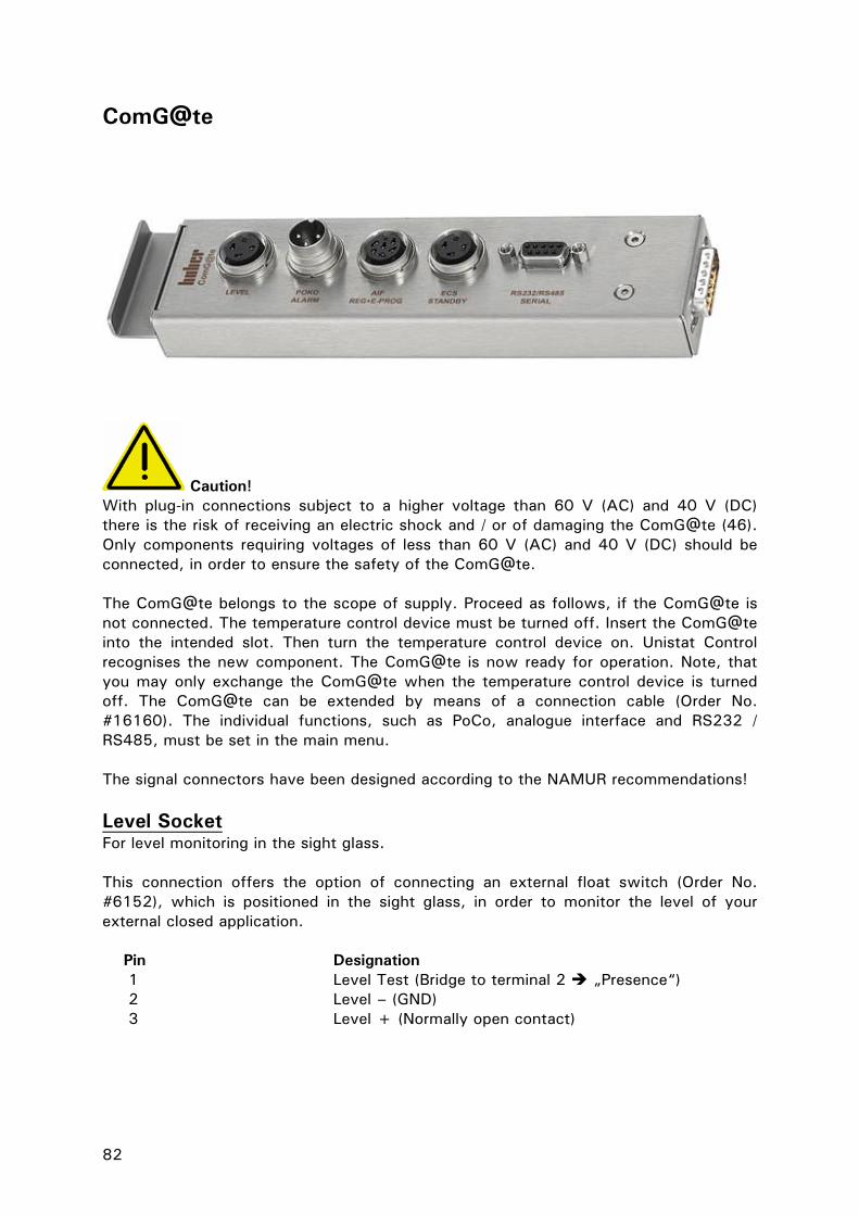
82
ComG@te
Caution! With plug-in connections subject to a higher voltage than 60 V (AC) and 40 V (DC) there is the risk of receiving an electric shock and / or of damaging the ComG@te (46). Only components requiring voltages of less than 60 V (AC) and 40 V (DC) should be connected, in order to ensure the safety of the ComG@te. The ComG@te belongs to the scope of supply. Proceed as follows, if the ComG@te is not connected. The temperature control device must be turned off. Insert the ComG@te into the intended slot. Then turn the temperature control device on. Unistat Control recognises the new component. The ComG@te is now ready for operation. Note, that you may only exchange the ComG@te when the temperature control device is turned off. The ComG@te can be extended by means of a connection cable (Order No. #16160). The individual functions, such as PoCo, analogue interface and RS232 / RS485, must be set in the main menu. The signal connectors have been designed according to the NAMUR recommendations! Level Socket For level monitoring in the sight glass. This connection offers the option of connecting an external float switch (Order No. #6152), which is positioned in the sight glass, in order to monitor the level of your external closed application. Pin Designation
1 Level Test (Bridge to terminal 2 „Presence“) 2 Level – (GND) 3 Level + (Normally open contact)

83
PoCo (Potential free contact) Alarm plug-in connector Signal contact for external monitoring. Observe the functional options, which the PoCo provides in the main menu. The potential free contact (PoCo) signals the condition of the machine by means of the contact position. A closed operating contact means ready status. The operating contact is open in case of a fault or error (this applies to the normally open contact between pin 1 and pin 2). The connection is designed as a potential free changeover contact. Normally open contact between pin 1 and pin 2. Normally closed contact between pin 2 and pin 3. Contact load: 1 A at 24 V DC Only use screened lines! AIF Reg-E-Prog Socket Analogue interface, one input channel (programmable) and 3 output channels. Analogue Interface The analogue interface of the ComG@te is programmed in the main menu. Please also read the description concerning the analogue interface in the section ComG@te menu. Pin Signal 1. Current output, T extern 0/4-20 mA or 0-10V 2. Current output, Set-point 0/4-20 mA or 0-10V 3. GND for analogue outputs GND 4. Analogue input (programmable) 0/4-20 mA or 0-10V 5. Current output, free programmable 0/4-20 mA or 0-10V 6. GND for analogue input GND ECS (External Control Signal) Standby Socket Release signal ECS (External Control Signal), for starting / stopping temperature control. Activation over a potential free contact. The contacts 1 and 3 are bridged internally. ECS becomes electronically active, if E1 and E2 are connected by an external potential free contact. The functionality of the ECS is determined in the main menu item Device Characteristics. The following variants are offered:
- Off: ECS does not have any effect (Factory setting). - 2nd set-point: The „2 nd set-point“ is taken over as soon as ECS is activated. - Standby: ECS has effect on tempering (On / Off).
Pin Signal 1,3 E2 2 E1

84
RS232 / RS485 Serial Socket A PC, an SPC or a process control system (PCS) can be connected to this socket, in order to remote control the controller electronics. Alternatively, connecting to a RS485 bus is also possible. Before connecting the line, check and if necessary adjust the settings in the menu Digit. Interface. Wiring RS232: Pin2 RxD Receive Data Pin3 TxD Transmit Data Pin5 GND Signal GND Wiring RS485: Pin6 A with 120 Ohm load resistance Pin7 A Pin8 B

85
Digital Interface with additional NAMUR-Commands RS232, Command Syntax, Namur-Commands RS232 Commands The signal interface is carried out over an RS232 Interface. Individual commands have been formatted in accordance with NAMUR recommendations (NE28). To use these commands the following communications protocol should be used: 1 Start bit 8 Data bits 1 Stop bit No parity The data transmission rate is set in the Main menu. Data flow control: The commands are not buffered. A new command may be sent as soon as the reply to the previous command has been received. If no reply is expected, then there should be a pause of 500 ms. Access method: Master (Computer / PCS), Slave (Thermostat), the Slave can only be activated by a signal from the master. Required response time: less than 500 ms. Further information on Command Syntax: Commands and parameters should be separated by a space.
- Parameters may be entered as floating point or integer numbers - The decimal point (code 46) is used in the floating point numbers - After the comma, two places are permitted (OUT-command) - A any character after the physical unit (e.g. °C, K,°F) will be ignored - A positive (+) sign is not required. - Parameters in an exponential format are not allowed.
Namur Commands IN_PV_00 Request internal (jacket) temperature IN_PV_02 Request external (process / reactor contents) temperature IN_SP_00 Request Temperature set-point IN_SP_05 Request current analogue set-point OUT_SP_00 Send set-point xxx.xx START Start temperature control STOP Stop temperature control STATUS Single digit -1 Alarm / Warning 0 OK / standby / manual stop 1 OK Temperature control / air-purging 2 Temperature control stopped remotely 3 Temperature control started remotely

86
Example Command Example for a possible temperature control task: Please note that the notation \r\n means that the CR LF (carriage return / linefeed) is used for the final characters of the command. The data to be transmitted is in “”. Master Slave Comment “START\r\n” Start temperature control “OUT_SP_00 21.2\r\n” Change set-point to 21.2 °C “IN_PV_00\r\n” Request internal temperature “20.5\r\n” Slave transmits temperature “IN_PV_02\r\n” Request process temperature “20.5\r\n” Slave transmits temperature “STOP\r\n” Stop temperature control If a reply is not expected, then a pause of 500 ms should be used.

87
Chapter 5: First aid for a fault condition The following sections can be found in this chapter:
- Messages - Display Error Messages - Alarm and Warning codes - Exchange of the electronics - Maintenance - Decontamination / Repair - Cleaning the surfaces - Checking the pump seal - Plug contacts

88
Messages
Messages which occur can be split into Warnings and Alarm messages. Please note that alarms generally cause the machine to stop temperature control. An alarm message is immediately displayed as text on the graphic display (60). After the reason for the alarm has been repaired, the machine must be switched off using the main switch (36), and then switched on again in order to reset the alarm. Warnings do not normally cause the machine to stop temperature control, however they give information concerning critical conditions within the machine or environment. If the conditions leading to the warning message are not improved, then there is a danger that the machine will stop with an alarm, as generally alarm limits are then exceeded. After the alarm or warning message has been acknowledged, then the graphic display (60) shows in the left upper corner a symbol (a stop sign for alarm messages, a triangle with an exclamation mark for warnings). By turning the rotary knob / key (61), alternatively by lightly touching the screen (with Unistat Pilot) the symbol can be selected. By pressing the rotary knob / key (61) a further information window opens up, in which the alarm or warning messages are chronologically shown. Turning the rotary knob / key (61) allows specific messages to be chosen.
89
Display Error Messages Alarms and Warnings
If an error occurs, the unit will display an alarm or warning message in clear text on the graphic display (60). Each error is allocated an error code. Errors are separated into three categories: Hard alarms (error codes -1 to -1023): When a hard alarm occurs, temperature control is immediately stopped. The unit must be turned off, using the main switch (36) and the error condition corrected. The unit can then be turned on again. If an alarm occurs during the unit start up and self-test, please contact Huber for advice. Soft alarms (error codes -1024 to -2047): These alarms also cause the temperature control to be immediately stopped. After clearing the error condition temperature control can be restarted without cycling power to the unit. Warnings (error codes -2048 to -4095) These warnings do not stop temperature control, and give important information about the condition of the unit, its environment, or the application. If steps are not made to correct the cause of the warning, there is the risk that an alarm condition may arise, for example if a condition causes the unit to exceed an alarm limit, or temperature. Once an alarm or warning is acknowledged a symbol will be shown in the upper left corner of the graphic display. A “Stop” sign indicates the presence of an alarm message, a “warning” triangle (black exclamation mark on a yellow triangle) indicates the presence of a warning message. By lightly touching the symbol on the touch-screen, a list of the stored messages will appear in place of the graphic display. The messages are stored and displayed in time / date order. The key / rotary knob (61) and buttons can be used to step through the messages in order, and display their corresponding text messages. System Messages These messages give the user more general information, such as the attempted entry of an invalid input, or set point. These messages do not generate an alarm. Each message should be acknowledged when it occurs, so as not to cover up the normal display screen.

90
Alarm and Warning codes Hard Alarms (not resettable) Code Message
-1 Set point tracing function has been selected, but no sensor is connected
Over temperature cut-off temperature reached
-40 Uneven structure size detected during data transmission
Standby current is too high.
-41
-42
-43
-44
-45 / -46
-47
Problem with Unistat RS232 communication
Problem with the return fluid temperature sensor
Problem with the evaporator end temperature sensor
Problem with Reserve sensor / Reserved for sensor problem
Problem with main power relay (Tr1)
Problem with temperature measurement.
Pump running current is too high.
An out of range signal has been connected to the A-D converter (OVR bit set)
Problem with the first reference sensor measurement
Problem with the second reference sensor measurement.
Pump pressure has dropped below the minimum value during temperature control.
-48
-49
-50
-51
-52
-53
-54
-55
-56
Evaporator temperature below minimum value
Evaporator pressure / temperature above maximum value
Refrigeration superheat is too low.
Discrepancy detected when reading EEPROM data.
Problem found during stepper-motor test
24-Bit A / D converter reference voltage out of range
Unistat Pump and Unipump signals not synchronised.
Unistat level signal detected without level switch being connected.
Pump rotating without signal
Transmission between 24bit A-D converter and processor has failed.
Problem with signal from stepper-motor module.
No pump pressure seen for excessive time period during degassing
Internal temperature sensor reading -151 °C (Pt100 open circuit temp. reading)
External temperature sensor reading -151 °C (Pt100 open circuit temp reading)
EEPROM cannot be read, despite multiple attempts
EEPROM cannot be read, despite multiple attempts
Mains power frequency cannot be confirmed
Measured A-D signal not correct (high oscillation / not steady)
-57
-58
-59
-60
-61
-62
-63
-64
-66
-67
-68
-69
-70
-71
-72
-73

91
-75
-76
-77
-78
-79
-80
-81
Level sensor detects that fluid level is too low.
Overpressure switch has tripped.
Expansion tank temperature too high – over temperature cut-off-
Mains power relay still closed – test current too high.
Heater current not detected
Mains voltage cannot be confirmed.
ComG@te not recognised when connected.
Machine type not recognised by unit software.
The controller software is not compatible with the unit.
The software does not recognise the controller hardware.
Controller hardware is not compatible with the unit.
Controller and Pilot software versions are not compatible.
Controller not calibrated.
Correct Configuration file not available
Correct Controller file not available.
-82
-83
-84
-85
-86
-87
Current test not completed due to over temperature cut-off
Controller and Pilot software not compatible.
RS communications Watchdog alarm
Temperature difference between internal and external temperature sensors too high.
Mains relay defect? Heater current too high when relay should be open.
Heater SSR defect? Heater current too high when SSR should be open.
Mains power relay is sticking.
Mains power frequency not recognised after timeout.
Out of range voltage applied to A-D converter channel 0. (OVR bit set).
Out of range voltage applied to A-D converter channel 1. (OVR bit set).
Out of range voltage applied to A-D converter channel 2. (OVR bit set).
Out of range voltage applied to A-D converter channel 3. (OVR bit set).
-88
-89
-115
Heater 1 defect? No current seen when Heater 1 switched on.
Heater 2 defect? No current seen when Heater 2 switched on.
Out of range voltage applied to A-D converter channel 5. (OVR bit set).
Out of range voltage applied to A-D converter channel 4. (OVR bit set).
-116
-117
-118
-119
-120
Out of range voltage applied to A-D converter channel 6. (OVR bit set).
Out of range voltage applied to A-D converter channel 7. (OVR bit set).
No Over temperature protection switch detected.
AD 7738 could not be initialised.
Over temperature protection switch EEPROM is blank.
The three sensors, OT-heating 1, OT-heating 2 and fluid outlet are checked for plausibility, in that while fluid is circulating the difference between these sensors must not to exceed +30 K over a longer period of time.
-74
-90 Heater 1 current too high – has not dropped to allow Heater 2 test to start.
-91
-92
-93
-94
-95
-96
-97
-98
-99
-100
-110
-111
-112
-113
-114

92
Over temperature at over temperature sensor 3 – Expansion tank
Over temperature sensor 3 short-circuit.
Over temperature sensor 3 open-circuit
Over temperature at over temperature reference sensor
Over temperature reference sensor short-circuit.
Over temperature reference sensor open-circuit
Set point for over temperature sensor 1 fluctuating
Set point for over temperature sensor 2 fluctuating
Set point for over temperature sensor 3 fluctuating
-121
-122
-123
-124
-125
-126
Error occurred when writing to over temperature switch EPROM.
Error occurred when reading from the over temperature switch EEPROM.
Error with 2 out of 3 comparisons from over temperature switch EEPROM.
Over temperature switch reset by Processor Watchdog
Over temperature switch reset by EEPROM Watchdog.a
Over temperature at over temperature sensor 1 – Heater 1
No CAN communication with over temperature switch
Over temperature signal present, but over temperature switch not responding.
Pilot RAM-Test aborted.
Graphic chip not recognised.
S1D13705 register not changed.
Configuration error (Simfile?)
-127
-128
-129
-130
-131
Over temperature sensor 1 short-circuit.
Over temperature sensor 1 open-circuit
Over temperature at over temperature sensor 2 – Heater 2
Over temperature sensor 2 short-circuit.
Over temperature sensor 2 open-circuit
NMI released in Unistat Control
Stack overflow in Unistat Control
Stack overflow in Unistat Control
Undefined OpCode in Unistat Control
Protection fault in Unistat Control
Illegal Word Operand in Unistat Control.-132
-133
-134
-135
-136
-137
-138
-139
-140
-141
-142
-512
-513
-514
-1000
-1016
-1017
-1019
-1020
-1022
-1023

93
Soft- (resetable) alarms Warnings
No pressure increase when pump runs. Pump dry ?
Unistat Control doesn’t recognise Unistat Pilot
Unistat Pilot doesn’t recognise Unistat Control.
Pump dry?
Control and Pilot Software versions are not compatible.
-1024
-1025
-1026
-1027
-1028
-2063 Main loop duration too long
-2064 Pump standstill pressure too high
-2065 Data set corrected while reading EEPROM file
-2066 Maximum number of messages
-2067 No significant external volume detected - set to lowest possible.
-2068 Heating turned off. Temperature difference between jacket and over temperature sensor too high.
-2069 Seven-segment display not functioning.
-2070 Graphic display not functioning
-2071 The pump-speed set point has been reduced. The pump could not reach the set speed e.g. because of high fluid viscosity.
-2072 The expansion tank temperature is within 5 K of the over temperature cut-off setting.
-2073 Maximum number of messages reached.
-2074 The compressor has been turned off because the internal temperature is more than 5 K below the minimum set point
-2075 Internal temperature exceeds the set point limits. Response: The maximum heating / cooling capacity has been reduced.
-2076 Problem with the 24 Bit A-D SPI Interface.
-2077 The temperature control has switched to the second set point because the RS Watchdog flagged an error.
-2078 The maximum number of messages in the AD7738 Interrupt Routine has been reached.erreicht.
-2079 The required evaporation pressure cannot be reached. Refrigeration leak / problem?
-2080 Strong noise seen on the value of AD7738 channel 0.
-2081 Strong noise seen on the value of AD7738 channel 1.
-2082 Strong noise seen on the value of AD7738 channel 2.
-2083 Strong noise seen on the value of AD7738 channel 3.

94
Exchange of the electronics
Disconnect the thermostat from mains power by turning the main switch (36) to “O”. Pull out the power plug. In the case of a problem with the electronics, you can exchange these parts yourself. For questions or difficulties please contact our representatives or ourselves.
- Remove the lock for securing the Unistat Pilot on the upper side of the Unistat, and pull the Pilot carefully up and away.
- Remove the securing screw on the Unistat Control and then carefully pull this also up and away.
- Place the replacement Unistat Control carefully in place ad fasten it with the securing screw.
- Place the replacement Unistat Pilot carefully in place and push down, then fasten in place using the lock at the top.
-2084 Strong noise seen on the value of AD7738 channel 4.
-2085 Strong noise seen on the value of AD7738 channel 5.
-2086 Strong noise seen on the value of AD7738 channel 6.
-2087 Strong noise seen on the value of AD7738 channel 7.
-3000 Clock battery drained.
-3001 Graphics library - initialisation error.
-3003 Graphics library – Coordinates outside of normal range.
-3006 Graphics library – out of memory.
-3007 Graphics library – device not available.
-3008
-3020
-3030
Graphics library – Error in enclosed system.
Graphics library – Error when processing list.
Graphics library – Error when processing button list

95
Maintenance
Danger! Prior to carring out cleaning on the machine switch off the machine via the mains isolator (36) and disconnect it from the mains.
There are few user-serviceable parts inside the unit. Other than the items listed below, maintenance should be carried out by Huber-trained and authorised personnel. Cleaning cooling fins (for air cooled machines with compressors only) To ensure that the temperature control unit will give the maximum cooling power the unit has to be freed from dirt (dust) from time to time. Please provide for an unrestricted air supply (discharge from heat loss, fresh air supply). Keep a distance of 20cm to walls for air cooled units. Identify the position of the air outlet, normally it is to be found at the front, with some other units it can also be found on the side, the rear or under the temperature control unit. Remove the air outlet grill to gain access to the cooling fins. With the help of a brush or vacuum cleaner, you can clean the fins of the black condenser at the back of the cabinet. However, never use pointed objects. Please see that the condenser fins are not damaged or deformed, as this may impair the air current. Cleaning the water filter (for water cooled refrigeration machines) Depending on water quality, the filter at the cooling water inlet has to be cleaned regularly. Customers isolation valves to be closed in cooling water outlet and return lines. Table models: Place a collecting vessel beneath the cooling water inlet (13). Inspect and clean the filter screen after having removed the cooling water inlet connection. Freestanding models: Remove the housing at the cooling water connections (13,14). Right behind the cooling water inlet there is the dirt trap. Carefully remove the lid (hexagonal). The metal cooling water filter and can be removed, rinsed and reinserted.
We are pleased to offer service training for users. Please contact Customer Support Team for further details.

96
Decontamination / Repair
The user is responsible for making sure that there are no hazardous materials either in or on the unit. The level of decontamination should be appropriate to the amount and type of contaminants on the unit. The user should refer to the appropriate MSDS information for advice. The decontamination should be done BEFORE outside personnel come into contact with the machine, and BEFORE the unit is sent out for repair or testing. The unit should be clearly labelled that it has been decontaminated before it is sent. We have prepared a document to simplify this process. This is available in the appendix, and at our website www.huber-online.com.
Cleaning the surfaces A normal steel cleaning spray is suitable for cleaning the stainless steel surfaces. Painted areas should be carefully cleaned with a gentle detergent.
Checking the pump seal
As rotating pump seals are never absolutely tight, operation with a thermal fluid that does not easily evaporate will cause drips to build up on the seal. These drips are collected. The draining drip tray (7) must be checked monthly, and emptied if required.
Plug contacts Each socket has a protective cap belonging to it. If a connector is not required, then it should be covered with this cap.
97
Chapter 6: Taking the machine out of service The following sections can be found in this chapter:
- Decommissioning - Transport - Disposal

98
Decommissioning Safety notice and policy
Caution! - Injury to persons or property possible: - Danger of slippage due to contaminated floor and working area. - Danger of tipping due to insufficient stability. - Danger of electric shock due to faulty power connection. - Danger of burns at extreme temperatures if touched. - Danger of chemical burns of the eyes, skin or airway due to emission of
dangerous vapours (with the appropriate thermal fluid). - Leakage of fluid remnants to be caught in a collecting vessel. Machine and floor
contamination to be removed at once!
All safety notices are essential and must be considered when working according to the operating manual! Switching off Set main switch (36) to “O”. Disconnect the thermostat from the power supply. Drain out cooling water (only with water cooled machines) Draining procedure: Customers isolation valves to be closed in cooling water outlet and return lines. Put a collecting vessel under the cooling water connections of the machine. Remove the closing cap on the cooling water drain. The water will begin to drain from the water connections. It is essential that the water is allowed to fully drain out to prevent danger of freezing during storage or transport!
The drained off cooling water can be tipped down the normal drains. The draining of the machine can be accelerated by blowing a compressed air pistol against the cooling water connections.

99
Transport The unit is now decommissioned and ready for transportation. The original packing material should be used as far as possible, and the unit must always be transported in the upright position. Items such as the controller and sight glass should be protected from transport damage. The unit should not be transported on its rollers, or mounting feet. Supports of rectangular wooden beams appropriate for the weight should be used even when transported on a palette. When shipping the unit on a palette, it should be braced on four sides using wood or other suitable materials. Extra bracing and banding should be made according to the weight of the unit. Extra materials such as plastic wrap / sheeting, cardboard, and banding should be used as necessary.
Disposal Thermal fluid which has spilled or leaked must be correctly disposed of. To minimise environmental pollution, please dispose of old temperature control machines only via suitably licensed and experienced disposal or recycling companies.

100
BESTÄTIGUNG / CONFIRMATION An / To: Huber Kältemaschinenbau GmbH Werner-von-Siemens-Str. 1 77656 Offenburg Von / from: Firma / company: Betreiber / responsible body: Strasse / street: Name / name: Ort / city: Funktion / function: Tel.: Gebäude / building: Fax: Raum / room: Email: Hiermit bestätigen wir, dass nachfolgend aufgeführtes HUBER- Temperiergerät: We hereby confirm that the following HUBER-equipment:
UNISTAT UNICHILLER MINISTAT CC Typ / Type: Serien-Nr. / Serial no: S mit folgendem Thermofluid betrieben wurde Was used with the below mentioned heat transfer fluid Beachten Sie bitte bei der Verwendung fremder Temperiermedien: Durch die Vielzahl unterschiedlicher Thermofluide sind wir gezwungen vor Beginn der Reparatur die Geräte zu spülen. Die dabei entstehenden Kosten müssen wir Ihnen in Rechnung stellen. Sie können die für Sie anfallenden Kosten niedrig halten, wenn sie das Gerät vor der Rücksendung mit Ethanol spülen. Vielen Dank! Please note that if you’re using none Huber heat transfer fluids we have to flush the system before we start with your repair. The resulting costs have to be added onto your bill. You can reduce your repair costs by flushing your system with ethanol before return. We appreciate your help! Darüber hinaus bestätigen wir, dass das oben aufgeführte Gerät sorgfältig gereinigt wurde, die Anschlüsse verschlossen sind und sich weder giftige, aggressive, radioaktive noch andere gefährliche Medien in oder am Gerät befinden. Additionally we confirm that the above mentioned equipment has been cleaned, that all connectors are closed and that there are no poisonous, aggressive, radioactive or other dangerous substances on or inside the equipment. Stempel Ort/ Datum Betreiber Seal City/ date responsible body
![Untitled-3 [tisch-env.com] · Copyright © 2014 Tisch International All Rights Reserved Tisch Environmental 145 S. Miami Ave Cleves, OH 45002 513-467-9000 sales@tisch-env.com www](https://img.pdfslide.us/doc/110x75/5ec53f1c320cc925d949c768/untitled-3-tisch-envcom-copyright-2014-tisch-international-all-rights-reserved.jpg)