Embed Size (px)
Citation preview

Nudura Online Basic Installation Training– Module Three

Objectives:To deliver an overview of Nudura ICF products, benefits of building with ICF’s, and a best practice guide for ICF installation.
Agenda:Module follows the NuduraInstallation Manual and Product Guide.

Disclaimer:
The information presented in this course gives the participant the necessary guidance and basic knowledge of proper installation techniques for using the various products composing the Nudura Integrated Building Technology and associated accessories (the “Nudura Products”).
This course DOES NOT train an individual how to be a contractor. Nudura Inc. and Nudura Systems, Inc. do not have any control over the installation or workmanship used in the assembly or installation of the Nudura Products, whether by recognized Nudura trained installers or by unauthorized installers

Safety FirstPersonal Protective Equipment (PPE):
Hard hats Safety bootsSafety glassesProtective gloves
Where erecting scaffolding or alignment system, all local safety codes and regulations must be met.Keeping a clean and efficient job site results in less chance of injury.Take proper precautions to protect workers from protruding rebar.

Tools

ToolsSpecific tools for ICF construction include:
• Rebar Bender and Cutter• Bolt Cutters• NUDURA Folding Saw• NUDURA Foam Guns and Low Expansion Spray Foam• Rubber Mallet• NUDURA Fiber Tape• NUDURA Protection Tape• Hot Knife• Concrete Vibrator• NUDURA Bit Kit

Nudura Tools Video

Site Preparation & Delivery

Site Preparation
•Keep a clean work site• Place backfill away from access route
• Ensure adequate room for delivery vehicles• Protect product on site from damage and
inclement weather
•Level area for pump truck• Provide proper access for concrete truck• Ensure all worksite hazards are marked

Product Packaging
Majority of Nudura products are plastic shrink wrapped or in boxes.Product should be additionally protected from snow and excessive UV rays.
Product PackagingStandard Form Bundles should be stored laying on side
Corner Form Bundles should be stored standing flat on interlock

FootingsDesigned to transfer and distribute loads. Vertical dowels provide support at the base of the wall. Dowels are to be placed at the center of the wall location.
Factors that can affect footing size or thickened edge slab:• Soil Type (Bearing Capacity)• Loading Conditions• Seismic Zones• Water Table
Footings should be level within ± ¼”(6mm)
Consult local Building Codes for required footing sizes, required dowel spacing and bar diameter

Footings
• Edge projection distance must be taken from face of concrete wall
• Footing thickness (T) must always be equal to or greater than the edge projection distance
• Footing shall always be on Undisturbed Soil

Footings
Ideal Step Footing Heights:
• Full height form- 18” (457mm)• Half height form- 8 ½” (216mm)
Half step allows both halves of form to be used
Consult Local Building Codes for Code compliant step heights

Nudura Footings Video

First Course Placement• All materials should be kept out of work area until layout is complete
• Once corners are established, place building line on footing or slab
• Mark door and window locations on footings
• Double check building dimensions and layout before work begins
• Mark location of any openings on the footing

First Course Placement• All Materials to be placed in middle of jobsite• Maintain a 6’ (1.83m) clearance around perimeter
• Bend and place all reinforcement at corner locations• Prepare safe and easy access in and out of jobsite• Keep jobsite clean

First Course Placement• Start the building layout at each corner on the longest wall• Work towards center of wall ensuring forms are tight end to end
• Avoid cutting corner forms. If a corner must be cut, additional strapping must be installed

First Course PlacementForm units are to be cut along form cut linesIf required cut is off of cut line:
• Move corner slightly to allow cutting on line • Install a vertical stack joint near center of wall
If a Vertical Stack Joint is necessary:
Butt the cut forms together end to end
Provide additional support to the joint on both sides of the wall
Form-Lock can be cut to span the joint to help maintain wall straightness
Additional bracing is required at the stack joint

First Course PlacementVertical Stack Joint

First Course PlacementOn the First Course NUDURA recommends:
• 8 Vertical Joint Clips (VJC) per corner form• 4 Vertical Joint Clips per standard form to standard form
VJC replaces having to tape or tie wire formsVJC will help to keep forms tight end to end
VJC will reduce labor during installation
Always check that the first course has the vertical joint clips installed before starting the next course

First Course PlacementT Connections can be made with either pre-formed T-Forms OR by using standard forms and site cutting the connection
• T Forms need to be considered in same manneras corner forms regarding placement and vertical joint clips
• Additional bracing is recommended on T Forms

First Course PlacementWhen site cutting a T connection, using the Nudura T-Form strap increases efficiency and strength of the area
• Mark location of T-Connection on main wall• Use Nudura folding saw to remove foam at
connection.• Cut web as shown in image
Note: When cutting forms ensure that no debris falls into the wall cavity. If some does, remove it prior to pouring the wall.

First Course Placement• Insert min 20” (508mm) long length of rebar
in web for support• Rebar must extend across cut web to full web
on each side of T Connection

First Course Placement• Hook NUDURA T-Form Support Strap over
rebar pieces and fasten to fastening strips with 2” (51mm) screws
• Straps should be installed 4 per course
• Gaps can be filled with NUDURA low expansion foam
• Caution should be taken when pouring any T connections as there is increased concrete pressure in this spot

First Course PlacementReinforcement in NUDURA Walls
• Controls cracking caused by concrete shrinkage around openings
• Increases strength against lateral loads (backfill, wind, seismic)
• Typical rebar is 10M (#4) or 15M (#5)
• Minimizes deflection

First Course Placement• Reinforcement is installed as per plans and specifications• Wall Reinforcement tables available in Appendix D of
Installation Manual
Below Grade ReinforcementTypically placed towards tension side (Inside) of the wall
Above Grade ReinforcementTypically placed in center of wall
Compression Tension
Backfill

First Course PlacementReinforcement Lap Splice
Applies to Horizontal and Vertical Reinforcement
Lap length can be calculated by:• 40 x reinforcement diameter for 40,000 psi steel (Grade 40)• 60 x reinforcement diameter for 60,000 psi steel (Grade 60)
Lap Splices can be contact or non-contact
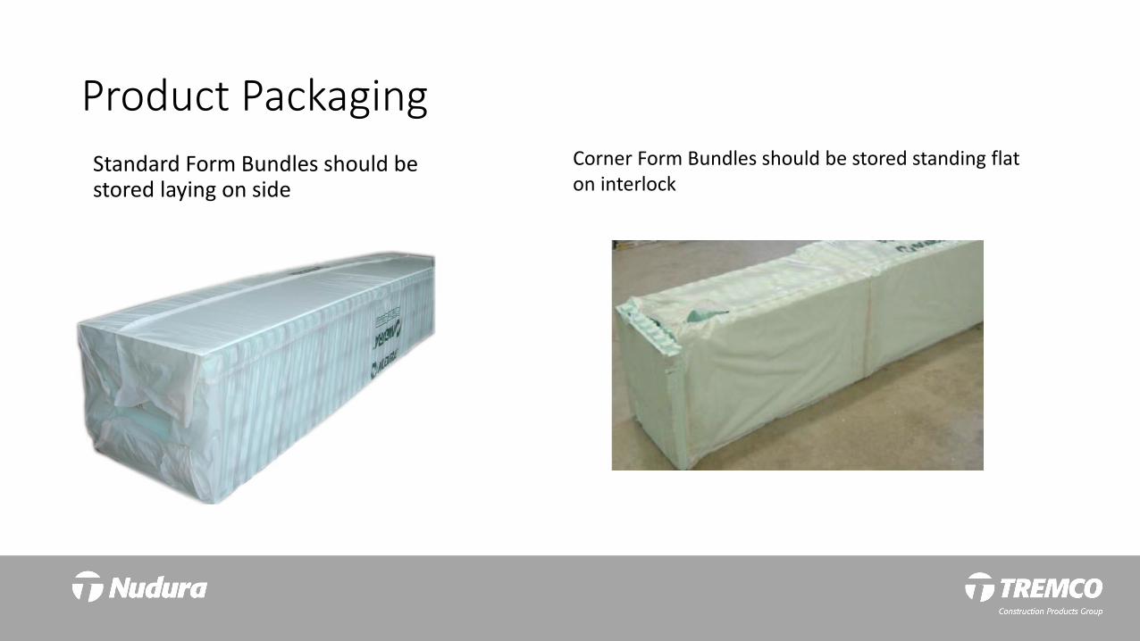
First Course PlacementContact Lap Splice• Occurs when reinforcing steel is touching and must be tie wired.
• If a contact splice is required bars must be lapped to appropriate length and tied together.

First Course PlacementNon-Contact Lap Splice
• Occurs when reinforcing steel is not touching• Separation between bars can not be more than 1/5th lap length to 6” (150mm) maximum

Reinforcement Video

Second Course PlacementStart second course at same corner as first course• 16” (406mm) off-set is established by reverse stacking of corner forms
• Four Vertical Joint Clips recommended to link corner form to standard forms

Second Course Placement• Horizontal Reinforcement will need to be offset from previous course by one notch location• Form-Lock is installed into second course to help maintain wall straightness
• Overlap each length of Form-Lock

Second Course Placement• Once second course is complete the forms need to be leveled• Forms can be shimmed (preferred) or cut to achieve a level wall

Second Course Placement• First Course can now be secured to footing using NUDURA Low Expansion Spray Foam

Additional Course Placement• The layout pattern of the first two courses of forms will be followed up the height of the wall
• This includes all cuts, reinforcement, lap splices, etc...
• Vertical Stack Joints will be maintained up the height of the wall
• Example: 1st, 3rd, and 5th course will follow same placement

Additional Course Placement Video

Plus FormsAdditional EPS Foam Laminated to Standard Form
Available Thicknesses:• 1” (25mm)• 2” (50mm)• 4” (100mm)• 6” (150mm)

R Value Plus FormsAdditional EPS Foam Inserts
Available Thicknesses:• 2” (50mm)• 4” (100mm)• 6” (150mm)

R Value Plus FormsAdditional EPS Foam Inserts
Available Thicknesses:• 2” (50mm)• 4” (100mm)• 6” (150mm)

Test your Knowledge!Return to the Module Three web
page and click on the Start Exam button.
Keep this presentation open while working through the exam.