Embed Size (px)
Citation preview

NUCLEAR WELDING, APPLICATION FOR AN LMFBR*
P. Patriarca and 6. H. Goodwin
Metals and Ceramics DivisionOak Ridge National LaboratoryOak Ridge, Tennessee 37830
ABSTRACT
Many studies have predicted that the Liquid Metal Fast Breeder Reactor
(LMFBR) will serve as a vital segment of our electrical energy system late in
this century. This reactor concept has design requirements and service
conditions that demand extremely high reliability. Fabrication of an LMFBR
system is discussed, with emphasis on areas where joining innovations have
been introduced. Each major component of the system, including reactor
vessel, intermediate heat exchanger, steam generator, and sodium-contaiment
piping, is treated separately. Development of special filler metals to avoid
the low elevated-temperature creep ductility obtained with conventional
austenitic stainless steel weldments is reported. Bore-side welding of steam
generator tube-to-tubeshcat joints with and without filler metal is desirable
to improve in spectability and eliminate the crevice inherent with face-side
weld design, thus minimizing corrosion problems. Automated welding methods
for sodium-containment piping are summarized; they minimize and control distor-
tion and ensure welds of high integrity. Selection of materials for the various
components is discussed for plants presently under construction, and materials
predictions are made for future concepts.
*Research sponsored by the U.S. Energy Research and DevelopmentAdministration under contract with Union Carbide Corporation.
- NOTICE-This report was prepared as an account of worksponsored by the United States Government. Neitherthe United States nor the United States EnergyResearch and Development Administration, nor any oftheir employees, nor any of their contractors,subcontractors, or their employees, nukes anywarranty, express or implied, or assumes any legalliability or responsibility for the accuracy, completenessor usefulness of any information, apparatus, product orprocess disclosed, or represents that its use would notinfringe privately owned rights.
MASTERmcni-unoN OFTHIS DOCUMENT ONUMITEB f,

mTRQDUCTMH
The production and utilization of energy in the United States arc topics m£
high current interest.1~f Figure 1 traces the sources and consumption of energy
In the United States2 for the period from 1850 to 1990. Total energy consuaad
has risen steadily (with the exception of a period during the great depression),
and trends indicate accelerated increases in deaand. The contribution of nuclear
power at the present time is only approximately 5% of the total energy constated
(Fig. 1).
The projected electrical generating capacity in the United States has been
forecast3 for the years 1970-2020; total generating capacity is projected to
increase tenfold during that period (Fig. 2). The contribution of fossil-fueled
plants could eventually decrease because of supply limitations of oil and natural
gas and the many alternate uses for coal. Nuclear power can fill the large and
ever-increasing gap between total demand and available supply of conventional
(nonnuclear) power. The light-water reactors (LWR) will satisfy much of the
near-term demand curve until limited available fuel supplies are exhausted.
Being "burners" of nuclear fuel, LWRs cannot proliferate endlessly because of
the fixed supply of natural fuel. Breeder reactors, on the other hand, can
circumvent the problem. By transmutation of naturally abundant fertile
isotopes to fissile isotopes which can be used as fuel, the breeder reactors
can create more fuel than they consume, and supply fuel to satisfy projected
power needs for several thousand years.1"5 The High-Temperature Gas-Cooled
Reactor (HTGR) is a "high-gain converter" which produces nearly as much fuel
as it consumes. It therefore can supply significant amounts of energy as great
as the breeder reactors can in the long term.
The projections shown in Fig. 2 do not include possible technological
breakthroughs that might make alternate energy sources, such as nuclear fusion

or solar energy, feasible. Although these sources are desirable, the uncer-
tainties involved prohibit planning on their availability.
THE LIQUID METAL FAST BREEDER REACTOR (LMFBR)
The components of an LMFBR system are shown schematically in Fig. 3.
Flowing liquid sodium is heated by the fuel in the reactor vessel, flows through
primary system piping to intermediate heat exchangers (IHX), where heat is
transferred to sodium in the secondary system and is finally pumped back to
the reactor vessel. The IHX isolates the radioactive primary sodium from the
secondary sodium facilitating routine maintenance of the secondary systems. In
the secondary system, heated sodium from the IHX(s) is pumped to the steam
generator(s) and returns to the IHX(s). The steam produced run3 a conventional
turbine generator.
LMFBR demonstration plants worldwide are compared in Fig. 4. At the
present time, the TJ.S.'s Clinch River Breeder Reactor Plant (CRBRP) is in the
design stage6 and will be preceded by the Fast Flux Test Facility (FFTF), a
materials testing reactor which does not produce steam. The discussions below
are primarily aimed at the CRBRP, although many of the observations and
conclusions apply equally to the FFTF and other worldwide demonstration projects.
The primary material of construction for the sodium pressure boundaries
is sustenitic stainless steel, with ferritic steel used in the steam generator
and steam piping.
AUSTENITIC STAINLESS STEEL WELDING
Despite the wide usage of austenitic stainless steels in chemical processing
and petrochemical systems, few data are available on the high-temperature
behavior of stainless steel weld deposits. Creep and cyclic loadings (fatigue
and creep-fatigue) data are keys to predicting the service behavior of welds.

4
These loading conditions will force materials to strain, and good ductility —
the ability to deform without fracturing — is a property of key importance.
The limited creep ductility data available show a high degree of scatter; aany
creep failures involve strains on the order of 1Z total elongation.7"* As a
result of the low creep ductility problem, an extensive stainless steel welding
study is in progress at the Oak Ridge National Laboratory (ORNL), involving
characterization of ferrite morphology, effects of electrode coatings, and
effects of slight compositional differences on properties.
FERRITE MORPHOLOGY
In order to avoid the occurrence of hot-cracking (fissuring) in austenitic
stainless steel weldments, it is common practice to assure that the weld deposit
contains a small amount of 6-ferrite. The relative amount of ferrite in the
austenite matrix depends upon the composition of the weld deposit.8'9 Also,
the morphology and distribution of the ferrite phase vary with welding process
and welding conditions within a given process.10
The microstructure present in several different types of austenitic
stainless steel weldments has been carefully characterized to determine whether
at least part of the observed property variations can be attributed to micro-
structural differences.10 The difference in chemical composition of the filler
metals used for four typical welds cause the overall mean ferrite content to
vary from 3.1 to 8.2 ferrite number (FN) as measured by the quantitative
television microscope (QTH). These results could not be predicted accurately
from the existing Schaeffler, McKay, or similar diagrams.
Further investigation revealed substantial variations in ferrite content
from weld to weld produced under identical conditions, from location to location
along the center line of a particular weld, and from point to point within a
particular transverse weld cross section, as shown in Fig. 5.

Also, the distribution and Morphology of the ferrite present varied
substantially in each of the mentioned locations. The ferrite was always
located at dendritic or cellular dendritic substructure boundaries, forming a
nore or less continuous network.
Mechanical properties tests indicated that the ferrite plays a najor role
in the fracture process at elevated temperatures. The fracture path almost
exclusively followed the location of austenite-ferrite boundaries in the as-
deposited weld metal, and the fracture surface reproduced the solidification
substructure in detail.
EFFECTS OF TYPE OF ELECTRODE COATING
Traditionally, shielded metal-arc electrode coatings are first evaluated
on such practical grounds as ease of deposition, bead contour, arc stability,
deposition efficiency, and ease of slag removal. Satisfactory bend and tensile
properties of the weld are also mandatory. The collection of long-time creep
data was not of major concern in the past because the applications have not
required such data. The influence of particular flux coverings on the creep-
rupture properties had received minimal attention. For this reason, ORNL
obtained creep data at 1200°F (649°C) on the type 308 stainless steel weld metal
deposited with the three most common types of E308 covered electrodes,11
having the "lime," "lime-titania," and "titania" type coverings. These are
general classes of stainless steel electrode coating formulas that are well
known and accepted throughout the welding industry. Each manufacturer has his
own proprietary formulations, but the lime-type covering generally contains
more calcium carbonate (limestone) and calcium fluoride (fluorspar) than the
titania-type covering, and the titania-type covering contains more titanium
dioxide (titania). The lime-titania covering is a compromise between the others.
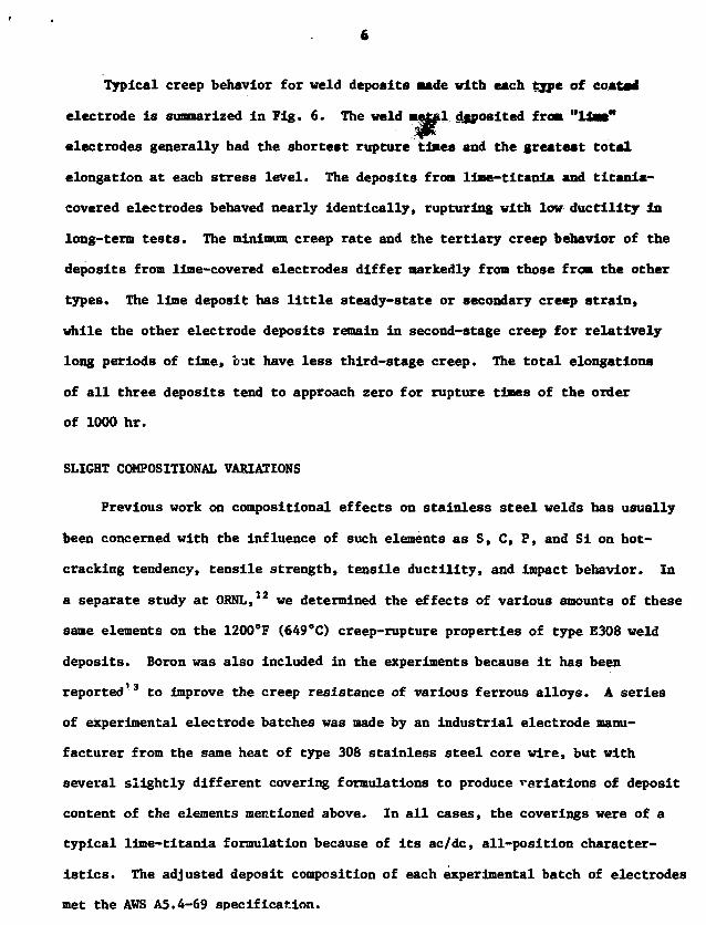
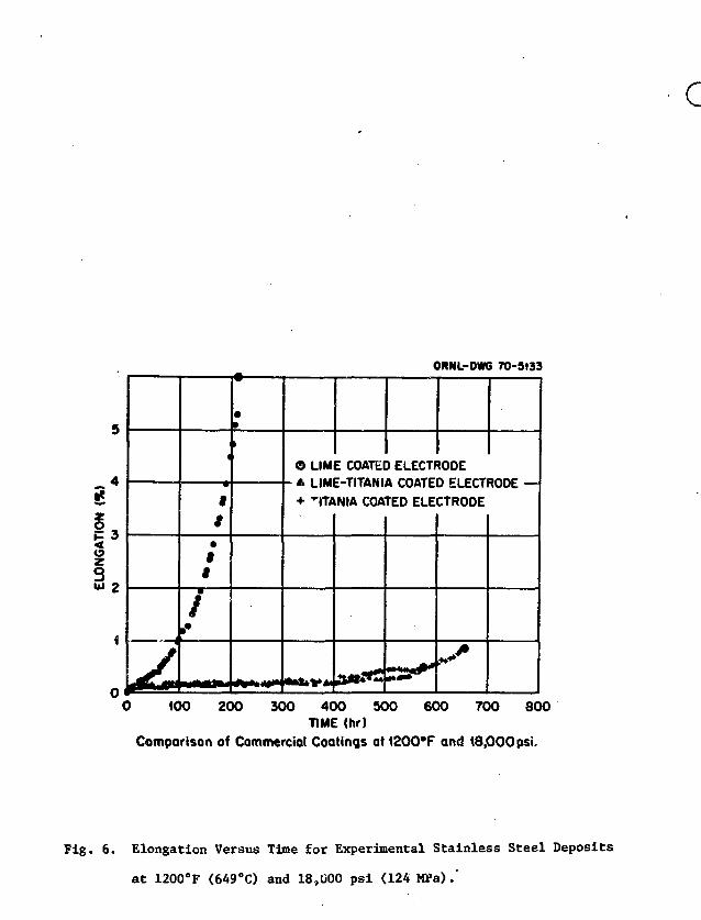
Typical creep behavior for veld deposits made with each tjpe of coatai
electrode is sumnarized in Fig. 6. The weld metfil deposited from "lias"
electrodes generally had the shortest rupture times and the greatest total
elongation at each stress level. The deposits from liae-titania and titania-
eovered electrodes behaved nearly identically, rupturing with low ductility in
long-term tests. The minimum creep rate and the tertiary creep behavior of the
deposits from lime-covered electrodes differ markedly from those from the other
types. The lime deposit has little steady-state or secondary creep strain,
while the other electrode deposits remain in second-stage creep for relatively
long periods of time, but have less third-stage creep. The total elongations
of all three deposits tend to approach zero for rupture times of the order
of 1000 hr.
SLIGHT COMPOSITIONAL VARIATIONS
Previous work on compositional effects on stainless steel welds has usually
been concerned with the influence of such elements as S, C, P, and Si on hot-
cracking tendency, tensile strength, tensile ductility, and Impact behavior. In
a separate study at OBNL,12 we determined the effects of various amounts of these
same elements on the 1200°F (649°C) creep-rupture properties of type E308 weld
deposits. Boron was also included in the experiments because it has been
reported13 to improve the creep resistance of various ferrous alloys. A series
of experimental electrode batches was made by an industrial electrode manu-
facturer from the same heat of type 308 stainless steel core wire, but with
several slightly different covering formulations to produce variations of deposit
content of the elements mentioned above. In all cases, the coverings were of a
typical lime-titania formulation because of its ac/dc, all-position character-
istics. The adjusted deposit composition of each experimental batch of electrodes
met the AWS A5.4-69 specification.

The creep behaviors of these velds were all similar at high stresses at
1200*F (649*C). Differences in creep behavior of the various deposits were
apparent at low stress and the resulting longer rupture times. Table 1 shows
the results of the creep tests run at 1200*F (649*C) under the relatively low
20,000 pel (138 MPa) static stress. The deposit with the highest carbon content
proved to be much stronger than the standard deposit under these conditions.
Lowering the carbon content below the standard did not appear to have any
significant effect on the rupture life of the deposit, but it did increase
rupture ductility. Adding boron to the type E30S deposit significantly inproved
both the rupture life and the rupture ductility. Lowering the amount of silicon
in the type E308 deposit markedly increased the ductility but decreased the
rupture life. There seems to be very little effect of sulfur content variations.
At a lower stress level of 18,000 psi (124 MPa) it became apparent that
additions of phosphorus and boron significantly strengthen the weld deposit and
add resistance to creep embrittlement.
BEHAVIOR OF OPTIMIZED ELECTRODE
An optimized E308 stainless steel electrode that produced deposits containing
0.007% B, 0.06% Ti, and 0.04% P was produced by an industrial manufacturer. It has
been designated type 308 CRE stainless steel for the controlled residual elements
it contains. We conducted an extensive mechanical properties and metallographic
investigation of welds deposited in 2 3/8-in.-thick (60 mm) type 304 stainless
steel plate with a double U-groove joint preparation.1*1 The test specimens were
taken from different locations within the weld and were categorized according
to distance from the nearest plate surface regardless of the side of the mid-
plane from which they came. They are designated LI for surface specimens, L2 for
one-third thickness specimens, and L3 for midplane specimens.

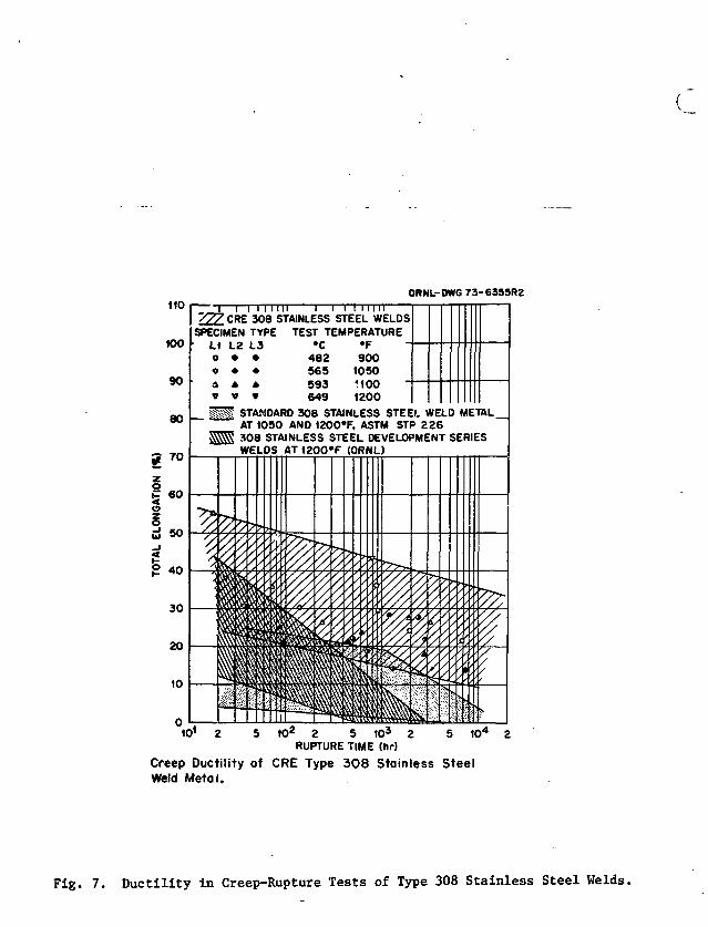
The superior elevated-temperature ductility of the type 308 CIS stainless
steel composition is evident in Fig. 7. All the total strain data for CII
weld metal are contained in a scatter band when plotted against rupture time;
comparable scatter bands are given for standard coaurcial weld metal and earlier
developmental welds in the ORNL program. The lowest observed total creep
strain for a CRE all-weld-metal specimens is 13Z. Internal cracks did not
develop at interphase boundaries.
The microstructure varied systematically through the thickness of the
weld. In the Initial passes at the center of the weld dislocation densities
are highest, dislocation loops form, cell structures form, and tfesC* carbide
precipitates on austenite-ferrite interfaces as a result of numerous thermal
and mechanical cycles experienced during multipass welding. The carbide
precipitate density, loop density, and dislocation density decrease gradually
toward the surfaces of the weld where less thermal and mechanical cycling
occurs. Near the surface few dislocation loops and no predpiate are present,
and the dislocation density is about a factor of 2.8 lower than near the center
of the weld. The dislocations near the surface are generally straight, with
only a hint of crude cell structure.
The systematic variations in creep properties at small and Jsirge strains
and in tensile properties are at least partly attributable to these microstructural
variations. Weld metal from initial passes tends to be stronger than that from
the final passes.
AUSTENITIC STAINLESS STEEL COMPONENTS
The primary material of construction for the sodium containment of today's
LHFBR, as mentioned earlier, is austenitic stainless steel. Thus, the metal-
lurgical considerations discussed above for welds are relevant to the fabrication
of the reactor vessel, intermediate heat exchangers, pumps, and primary and
secondary sodium piping.

REACTOR VESSEL
A schematic of the CRBRP reactor vessel is shown in Fig. 8. It is rougHly
55 ft tall and 20 ft In diameter (17 by 6 m) and is constructed of type 3**
stainless steel plate, nominally 2 3/8 in. (60 mm) thick. Sodium, flowing at
a rate of 41.5 x 10* lb/hr (5230 kg/sec) enters the reactor at 73O*F (388NS),
passes through the core, and leaves the reactor at 995*F (535aC). The reactor
vessel for the FFTF is nominally the same size and operates at essentially the
same temperatures. It was fabricated by a commercial manufacturer* using type 308
CRE coated electrodes for all structural welds. A view of one of the shell
courses under construction is shown in Fig. 9.
INTERMEDIATE HEAT EXCHANGERS
A schematic of one of the three intermediate heat exchangers for the
CRBRP is shown in Fig. 10. It is roughly 48 ft tall and 9 ft in diameter
(15 by 2.7 a). It is a counterflow shell-and-tube design with the primary
sodium on the shell side. Again, the FFTF uses a similar design. Figure 11
shows an IHX for FFTF under construction at a commercial manufacturer's plant.15
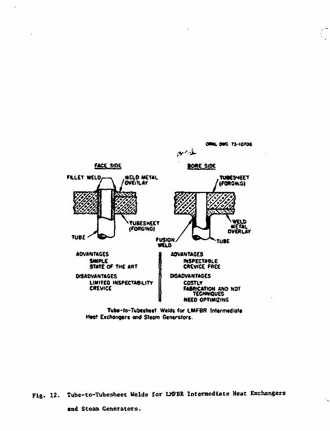
A distinctive feature in U.S. designs of both IHXs and steam generators
for LHFBR service is the "bore-side" tube-to-tubesheet weld. Figure 12 shows
the bore-side weld compared with the conventional face-side weld. The bore-
side weld Is desirable to avoid the presence of the crevice between the outside
of the tube and the tubesheet, and to provide a joint that is amenable
to radiographic inspection. It is, however, a costly and difficult weld to
produce, since the welding head oust be inserted inside the bore of the tube,
through a tubesheet that was over 6 in. thick for FFTF, and that will have
similar thickness for CRBRP. Depending upon the type of welding equipment
*Combustion Engineering, Inc., Chattanooga Div., Chattanooga, Tennessee.

10
used and the size and wall thickness of the tubing for C8BIP, filler natal say
be added to the weld joint at additional cost and with some procedural
complication. Inert gas shielding is used on the outside of the tube to
protect the root of the weld from oxidation. Radlographic inspection to nuclear
core requirements is performed by inserting the radiation source, either a
radloisotope "pill" or an x-ray tube of the "pencil-anode" type, into the bore
of the tube and exposing film placed around the weld joint outside the tube.
PUMPS
A schematic of one of the six pumps (three primary and three secondary)
for CRBRP is shown in Fig. 13. It is approximately 57 ft tall and 12 ft in
diameter (17 by 3.7 m ) . It is a free-surface centrifugal unit driven by a
500-hp (373 KW) variable speed motor, capable of 33,700 gpm (2.13 a'/sec).
Figure 14 shows one of the FFTF pumps under construction at a commercial
manufacturer's plant.15
SODIUM PIPING
A schematic plan view of the heat transport system arrangement for CRBRP
Is shown in Fig. IS. The primary and secondary hot-leg piping is 36 in. (0.91 m)
in diameter, while the primary and secondary cold-leg piping is 28 in. (0.71 m)
in diameter. Large expansion loops are included in the design to accomodate
thermal expansion. Sodium piping for the FFTF is somewhat smaller, 28 in. in
diameter for the hot legs and 16 in. (0.41 m) in diameter for the cold legs.
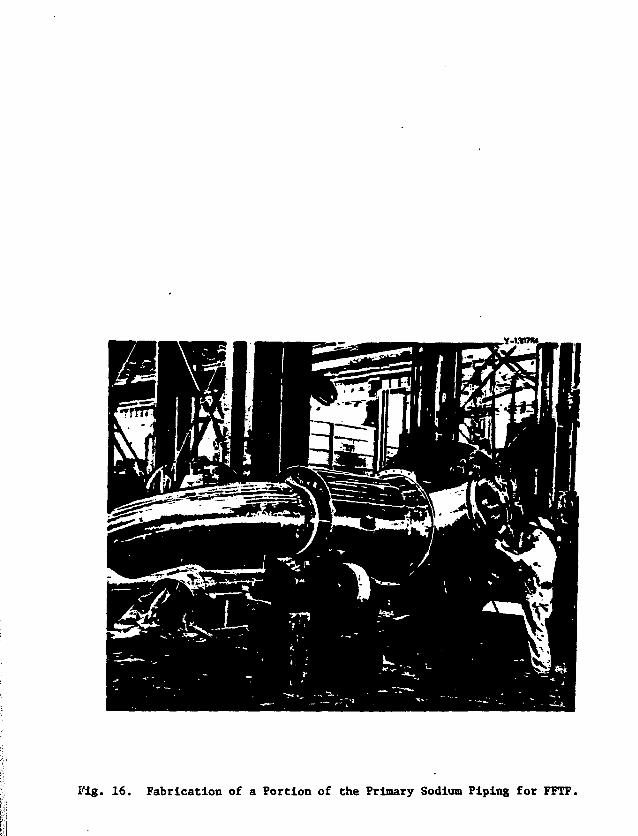
The sodium piping for an LMFBR provides a challenging design situation.
The wall thickness of the piping is in fact determined by a compromise between
two contradictory considerations. Loading from the internal pressure, gravity,
and particularly thermal expansion, calls for increased wall thickness, while
the thermal excursions due to rapid changes in cooiant temperature during normal
start-ups and shutdowns, as well as off-normal conditions, makes a thin wall

11
desirable. Thus, the wall thickness of all primary sodiusi piping for FFTF
is a modest 3/8 in. (9.5 mm) (see Fig. 16).
The use of large diameter, thin-walled pipe demands that the pipe welds
be of high integrity. Further, diametral shrinkage must be minimized in these
welda to avoid the stress concentrations that result from geometric disconti-
nuities. Both these considerations may be resolved in part by the use of
automated orbital pipe welding. The reproducibillty and process control that
can be achieved with an automated process c«nnot be matched by manual techniques.lt>17
Further, by careful selection of welding process variables (heat input, number
of passes, etc.), diametral shrinkage can be reduced to acceptable levels.If»lf
Another factor that must be considered is the present and future availability
of skilled construction welders to accommodate the increasing demand for their
services. A potentially serious shortage is predicted,20 but automated welding,
if applied on a large scale, can achieve higher productivity than comparable
manual techniques.17
Figure 16 shows a portion of the primary piping for FFTF under construction
at a commercial manufacturer's plant.*
FERSITIC STEEL WELDING
Whereas types 304 and 316 stainless steels can be welded without preheat
or postweld heat treatment, ferritic steels cannot. The added requirements for
process control and fabrication complications are not trivial in fabricating
components for nuclear service .
However, the relative susceptibility of the austenitic stainless steals
to corrosive attack in water containing chlorides and/or caustic limits the
use of these materials in steam generations systems. They can be used in dry
steam (e.g., superheaters) if precautions are taken to avoid carryover from the
*Combustion Engineering, Inc., Chattanooga Div., Chattanooga, Tennessee.

12
supersaturated ("wet") portions of the system. The conservative approach is
to use ferrltic steels for the entire steam system. Such an approach is
planned for the CKBKP.
STEAM GENERATORS
A schematic of one of the nine steam generators (six evaporators and
three superheaters) for CRBRP is shown in Fig. 17. Each unit is approximately
65 ft in length and 4 ft in diameter (20 by 1.2 m) and each is constructed
entirely of 2 1/4 Cr-1 Mo steel. Since the FFTF has no steam generators, the
design will bs verified by model and full-scale tests before CRBRP operations
commences. Each unit has 757 tubes and therefore 1514 bore-side tube-to-tubesheet
weld..
The desirability of bore-side welds is perhaps most vividly illustrated
by the experience with the Alco/BLH steam generator.21 This unit was
performance tested at the Liquid Metal Engineering Center,29 and subsequently
destructively examined at the Oak Ridge National Laboratory.21 It was of
bimetallic construction, using type 316 stainless steel for all sodium-exposed
surfaces and Inconel alloy 6C0 for all steam/water-exposed surfaces. Faulty
tube-to-tubesheet welds, however, allowed sodium-water contact, and caustic
stress-corrosion cracking progressed from the tube-to-tubesheet crevice
throughout the 6-in.-thick (0.15-m) tubesheet, finally linking with the outer
surface of the unit (Fig. 18).
TRANSITION JOINTS
The use of austenitic steels in the sodium system and ferritic steels
in the steam system necessitates transition joints between these two materials,
usually near the inlet and outlet of the steam generators. Although such
joints have been used for many years,23 the factors that control their perfor-
mance are poorly defined. Typically, the filler metal used has a thermal

13
coefficient of expansion intermediate to the joined austenitic (high) and
ferritlc (low) steels. Thermal cycling can lead to low-ductility failure
near the fusion line in the ferritic steel.2*
MATERIALS CONSIDERATIONS
Throughout the above discussion, the materials of construction for both
FFTF and CRBRP were identified without justification for their selection.
Clearly, the process of materials selection is a complex one, and many different
factors must be considered.25>26
Austenitic stainless steels have several significant advantages over other
materials for use in the sodium systems of an LMFBR; high-temperature design
ASME Code rules are established, a large mechanical properties data base exists,
product forms are readily available, strength is adequate, and corrosion and
mass-transfer resistance is suitable. However, there are persistent problems with
the use of unstabilized austenitic steels, which have been known and endured
for years, particularly the material's susceptibility to stress-corrosion
cracking and intergranular attack.
The use of 2 1/4 Cr-1 Mo ferritic steel for steam generators imposes a
limitation on the maximum steam temperature that can be used. This limitation
is due to the decrease in strength of that material at temperatures above 850°F
(454°C). Such considerations indicate that the materials selection process will
be continually reviewed, and that as service experience is gained in the demon-
stration plants, and as alloy development continues, alternate materials may show
advantages that would lead to their use in future LMFBR plants.
SUMMARY
The energy demands of the United States are projected to increase. Nuclear
power, in the form of the LMFBR, will likely be called upon to fill the gap
between demand and supply.

14
The LMFBR is a sodium-cooled reactor system, which can produce electrical
power and breed, assuring the capability for energy production to meet projected
needs.
A typical system consists c-f a reactor vessel, intermediate heat exchanger(s),
pump(s), sodium piping, and steam generator(s). The United States' effort
centers around the FFTF, a non-steam-producing test reactor and the CRBRP, a
large-scale demonstration reactor. The primary material of construction for
the sodium-containment is austenitic stainless steel, with ferritic steel used
in the steam system.
Conventional austenitic stainless steel weldments must be carefully
analyzed when used in critical applications at elevated temperatures because
generally they have low ductility in creep-rupture tests. The ferrite level
is influenced by composition and varies with welding process, from weld to weld
produced by a given process, and from location to location within a given weld.
The low-ductility fracture path almost exclusively follows the austenite-
ferrite boundaries.
Shielded metal-arc electrode coatings strongly influence the creep-rupture
properties of austenitic stainless steel weldments. Lime-covered electrodes
produced welds that were weaker but more ductile than either lime-titania or
titania-covered electrode welds. Variations in the amounts of S, C, P, Si, and
B affected the creep-rupture properties of austenitic stainless steel welds. An
optimized electrode composition, designated "CRE" (for controlled residual
elements), was developed; it produced deposits containing 0.007% B, 0.06% Ti,
and 0.04% P. Compared with standard commercial weld metal, the CRE material
exhibits equivalent strength and superior creep-rupture ductility.
The fabrication of each major component for an LMFBR is described. Bore-
side tube-to-tubesheet welds are used for both intermediate heat exchangers

15
for FFTF and steam generators for CRBRP. Automated welding is highly desirable
for critical sodiinc piping welds.
Austenitic-ferritic transition joints are required in current systems,
and the factors that control their performance are poorly defined.
The selection of materials for a given component will be continually
reviewed, and alternate materials may eventually show advantages that would
lead to their use in future LMFBR plants.
ACKNOWLEDGMENTS
The breadth and duration of the work described in this paper preclude
individual recognition of all who have contributed to its progress. The
cooperation and counsel of staff members of Combustion Engineering, Inc.,
Chattanooga Division, Westinghouse-Tampa Division, Foster Wheeler Corporation,
and Westinghouse Advanced Reactors Division have been invaluable. Within
the Oak Ridge National Laboratory, members of many groups, including Welding
and Brazing, Mechanical Properties, Metallography, Electron Microscopy, and
the Reports Office have contributed.

REFERENCES
1. Culler, F. L., Jr.9 and Harms, W. 0., "Energy from Breeder Reactors,"
Fhys. Today 25, No. 5 (May 1972), pp. 28-39.
2. "Fast Breeder Reactor Report," Edison Electric Institute, New York,
EEI Pub. No. 68-28, April 1968.
3. "Report of the EEI Reactor Assessment Panel," Edison Electric Institute,
New York, EEI Pub. No. 70-30, 1970.
4. Weinberg, A. M., "The Short Term Nuclear Option," Report of the Cornell
Workshops on the Major Issues of a National Energy Research and
Development Program, Cornell University, Ithaca, N.Y., 1973.
5. Report of the Liquid Metal Fast Breeder Reactor Program Review Group,
ERDA-1, Energy Research and Development Administration, Washington,
January 1975.
6. Clinch River Breeder Reactor Plant, prepared by Westinghouse Electric
Corp., Pittsburgh, for Breeder Reactor Corp., October 1974.
7. Voorhees, H. R., and Freeman, J. W., The Elevated-Temperature Properties
of Weld-Deposited Metal and Weldments, ASTM Spec. Tech. Publ. 2263
American Society for Testing and Materials, Philadelphia, 1958.
8. Schaeffler, A. L., "Constitution Diagram for Stainless Steel Weld Metal,
Metal Progr. 56, No. 5, November 1949, pp. 680-680P.
9. Delong, W. T., Ostrom, G. A., and Szumachowski, E. R., "Measurement and
Calculation of Ferrite in Stainless Steel Weld Metal," Weld. J. (Miami)
35, No. 11, November 1956, pp. 521-S-528-S.
10. Goodwin, G. M., Cole, N. C , and Slaughter, G. M., "A Study of Ferrite
Morphology in Austenitic Stainless Steel Weldments," Weld. J. (Miami)
51, No. 9, September 1972, pp. 425-s-429-s.
11. Binkley, N. C , Goodwin, G. M.. aad Harman, D. G., "Effects of Electrode
Coverings on Elevated Temperature Properties of Austenltlc Stainless
Steel Weld Metal," Weld. J. (Miami) 52, No. 7, July 1973, pp. 306-s-311-s.
12. Binkley, N. C , Berggren, R. G., and Goodwin, G. M., "Effects of Slight
Compositional Variation of Type E308 Electrode Deposits," Weld. J. (Miami)
53, No. 2, February 1974, pp. 91-s-95-s.
13. Heger, J. J., "Residual Elements in Stainless Steel — General Characteristics,"
in Effects of Residual Elements on Properties of Austeniti-c Stainless Steel,
ASTM Spea. Tech. Publ. 418, American Society for Testing and Materials,
Philadelphia, (July 1967), p. 134.
14. King, R. T., Stiegler, J. 0. and Goodwin, G. M., "Relation Between
Mechanical Properties and Microstructure in CRE Type 308 Weldments,"
Weld. J. (Miami) 53, No. 7, July 1974, pp. 307-s-313-s.
15. Westinghonse Nuclear Energy Digest, Vol. 3, Westinghouse Electric Corp.,
Westinghouse Nuclear Energy Systems, Pittsburgh, (1974).
16. Goodwin, G. M., and Slaughter, G. M., "Automated Welding of Stainless
Steel Piping Systems," paper presented at the 55th Annual Meeting of
the American Welding Society, Houston, Texas, May 6—10, 1974.
17. Goodwin, G. M., and Slaughter, G. M., "Automated Welding of Aluminum
Pipe," paper presented at the 56th Annual Meeting of the American Welding
Society, Cleveland, Ohio, April 21-25, 1975.
18. Downey, J. C , Hood, D. W., and Reiser, D. D., "Shrinkage Evaluation in
Mechanized Welded 16-in.-diam Circumferential Pipe Joints," Aerojet Nuclear
Company, Idaho Falls, Idaho. USAEC Report ANCR-1121, August 1973.
19. Condron, K. J., "Final Report on Weld Shrinkage Induced by Automated
Gas Tungsten Arc Welding," Bechtel Power Corporation, San Francisco,
April 22, 1973.
20. Smith, W. R., Sr., "Nuclear Construction — Some Difficulties and
Challenges," paper presented at the Welding and Testing Technology
Exhibition and Conference (WATTec), Knoxville, Tenn., Feb. 21, 1974.
21. DeVan, J. H., and Slaughter, 6. M., "Post-Test Examination of Alco/BLH
Sodium-Heated Steam Generator," Oak Ridge National Laboratory, Oak Ridge,
Tenn. USAEC Report ORNL-4950, May 1974.
22. Performance Evaluation of Beat Exchangers for Sodium-Cooled Reactors*
United Nuclear Corporation, Elmsford, N.Y. USAEC Report UNC-5236, June 1969.
23. King, J. F., "Behavior and Properties of Welded Austenitic Stainless-
to-Ferritic Steel Transition Joints — A Literature Review," Oak Ridge
National Laboratory, to be published.
24. Barford, J., and Probert, K. S., "Interfaclal Effects in Dissimilar
Steel Joints," Centra]. Electricity Generating Board, Marchwood Engineering
Laboratories, International Conference on Welding Research Related to
Power Plants, Sept. 17—21, 1972.
25. King, R. T. (Chairman), "Report of Task Force on Alternate Structural
Materials for Liquid Metal Fast Breeder Reactors," Oak Ridge National
Laboratory, Oak Ridge, Tenn., ERDA Report, to be published.
26. Patriarca, P., ORNL Five-Year Plan for Materials for Advanced LUFBR
Steam Generators, Oak Ridge National Laboratory, November 1974.

Table 1. Effect of Compositional Variables on Clie CreepProperties of Shielded Metal-Arc £308 Sealiless SteelWelds at 1200°F (649°C) and 20,000 (138 M M )
Compositional Variables Rupture^Time Total Elongation
Standard llme-titania 363 2.0coveringa
Carbon, %Low, 0.035 346 - 4.0High, 0.074 1334 1.75
Silicon, %Low, 0.29 127 15.7High, 0.73 651 1.3
Phosphorus, %Medium, 0.023 166 9.6High, 0.034 1329 4.35
Sulfur, %Low, 0.006 333 2.6High, 0.027 292 4.05
Boron, %Medium, 0.004 1167 7.5High, 0.006 1159 7.8
a0.044% C, 0.47% Si, 0.012% P, 0.016% S, 0.001% B.

FIGURE CAPTIONS
Figure 1. United States Energy Sources and Consumption.
Figure 2. Projected Generating Capacity for the Tears 1970-2020.
Figure 3. The Liquid Metal Cooled Fast Breeder Reactor.
Figure 4. Comparison of Demonstration Plants Worldwide.
Figure 5. Variation in Ferrite Distribution in one Cross Section of
a Gas Metal-Arc Weld Sample. Etchant: KOH, K3Fe(CN)6.
Figure 6. Elongation Versus Time for Experimental Stainless Steel
Deposits at 1200°F (649°C) and 18,000 psi (124 MPa).
Figure 7. Ductility in Creep-Rupture Tests of Type 308 Stainless
Steel Welds.
Figure 8. Schematic of CRBRP Reactor Vessel.
Figure 9. Fabrication of a Shell Course of the FFTF Vessel.
Figure 10. Schematic of CRBRP Intermediate Heat Exchanger.
Figure 11. Fabrication of an IHX for FFTF.
Figure 12. Tube-to-Tubesheet Welds for LMFBR Intermediate Heat Exchangers
and Steam Generators.
Figure 13. Schematic of CRBRP Primary Sodium Pump.
Figure 14. Fabrication of a Primary Sodium Pump for FFTF.
Figure 15. Schematic of CRBRP Heat Transport System Arrangement.
Figure 16. Fabrication of a Portion of the Primary Sodium Piping for FFTF.
Figure 17. Schematic of CRBRP Steam Generator.
Figure 18. Section of Alco/BLH Steam Generator Tubesheet.

MO
to
•0
10
t «0
i *°«0
\ \
Umm Itnrfon. l«c
CNCIWV
« 0
• 0
90 »
m
40
»
•0
(MO WD IMO WO W
UNITED STATES
D *W0 IMO MK <M0 IMO IM3 « t »I t M
ENERGY SOURCES AND CONSUMPTION
Fig. i . United States Energy Sources and Consuaption.

•-,*.
* = . ' • - • I.-
Fig. 2. Projected Generating Capacity for the Years 1970-2020,

FAST-BREEDERTHE UQUID-METAL-COOLED
Turbine-generator
1450psi BandcondenserIntermed-
iate heatexchanger
SteamgeneratorSodium
pump
Primary sodium loop Secondary loop " Steam-heat transfer
Fig. 3. The Liquid Metal Cooled Fast Breeder Reactor.

v-uaanCOMTMISON OF OCMO HANTS WOILD WIDE
UK French Germany tumla Japan USm PHENIX SMt IN-350 MONJU CTMf
Theraal output, MWI
Electrical output, MW«
taaclor
MJua outlet ton?. *fio&xm Inlel tone, *F
Steam Generator
S«?un Inltt l*np, * f
Sotftum outlet r»»D, *F
FM«Watar tnhl )MBI , *F
^•Mf^tf irami IMim *r
NuAwoFlecft
Nwbtr «T unit! or modulw
aSO
270
1044
752
990
tsoS50955
2300
3
#•
S63230
I03D
750
1022
«6247S«55
7400
3
I0*4
720300
1000
700
977
644
545
950
2400
311*
1000
350*
932
573
•42
455
316
t15J35
•»
24'
714
300
1005
734
959oOt
400905
1940
3
9»
9753»
*9S
no
936
651499
9001450
3
9»
y t • 200 MW(.) oaia»lr«, 150 MW(.) |kOm lo*> en MaiaV-
nvc9 #wi ofOloff« ttkfM tuptnitottrtf H w i r#hwiNpTB * oiw coch put loop*'Xttktftl* ••oporatan, 36 mptrfwotan, 36 ™ W « - 12 aoch par loop.*Mna iwaoraton, n)na mparhtotan - thrM aach par leap.Tvctv* e»apBraran, 12 wparhaolan, fmo each pat loop.*Tnra» wpeiatuii, rhraa tuptihaatari, thna rahaotart • one each par loap.' S t anapuiatuii, thraa •uparhaatan - two •vaporaton eni en* auaariwatar par loop.
•-J4-74
r- 0
Fig. 4. Comparison of Demonstration Plants Worldwide.

5- !'* •f-*.j"<&Z/>\
SUHFACE
FEUITE OlSTtllUTlON
nKITMa I IMCFUSION LINE
I N A GAS METAL ARC WELD SAMPLE
Fig. 5. Variation in Ferrlte Distribution in one Cross Section of a
Gas Metal-Arc Welti Sample. Ktchant: KOH, KaFe(CN)6.
r
c
ORML-DWG 70-9133
MM
$
ti
M
f
r
MM
m
mt
i
o- A
+
LIME COATED ELECTRODELIME-TITAN IA COATED ELECTTrra NIA COATED ELE
mm
CTRODE
0 100 200 300 400 500 600 700 800TIME (hr)
Comparison of Commercial Coatings at 1200°F and 18,000psi.
Fig. 6. Elongation Versus Time for Experimental Stainless Steel Deposits
at 1200°F (649°C) and 18,000 psi (124
ORNL-OWG 73-6355RZ110
100
90
80
jf 70
! "UJ 50
g
7 7 7 CRE 308 STAINLESS STEEL WELDSSPECIMEN TYPE TEST TEMPERATURE
LI L2 L3 »C »Fo • • 482 900© • • 565 1050a * * 593 1100v v » 649 1200
STANDARD 308 STAINLESS STEEL WELD METALAT 1050 AND 1200*F, ASTM STP 2 2 6308 STAINLESS STEEL DEVELOPMENT SERIESWELDS AT1200»F (ORNL)
40
30
20
10
101 2 5 102 2 5 103 2 5 10"RUPTURE TIME (hr)
Creep Ductility of CRE Type 308 Stainless SteelWeld Metal.
Fig. 7. Ductility in Creep-Rupture Tests of Type 308 Stainless Steel Welds.
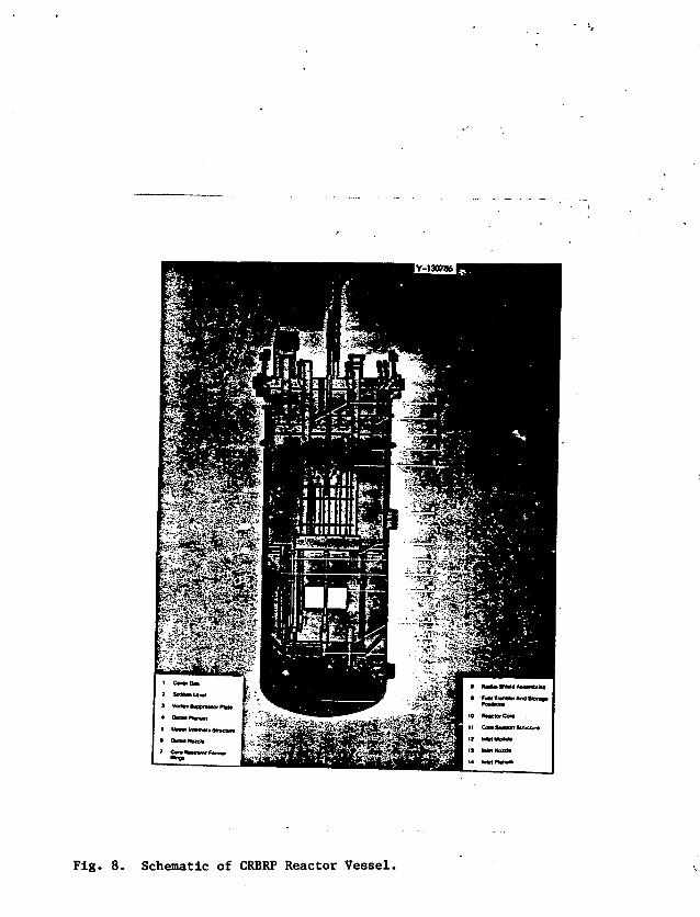
Fig. 8. Schematic of CRBRP Reactor Vessel.

Fig. 9. Fabrication of a Shell Course of the FFTF Vessel.

• OuttrShroud
• Otnmcomar
10 Primvy Intct
1 BafllM A Tub* Support
12 Shan
13 Primary
Fig. 10. Schematic of CRBRP Intermediate Heat Exchanger.

. * * ?• •
- / ' • *
f
Fig. 11. Fabrication of an IHX for FFTF.
OMNU O K 73-IO7OC
FACC 1OHE SlDC
FILLET WELO, .W£U> METALfOVERLAY
TUBE
ADVANTAGESStMPtESTATE OF THE ANT
DISADVANTAGESUMITEO INSPECTASitlTYCREVICE
TUtCSHEET
WEU>METAt
OVERLAY
ADVANTAGESINSPECTA8LECHEVfCE FflEE
OtSAOVANTAGESCOSTLYFA8IHCATION AND NOT
TECHNKHJESNEEO OPTIMIZING
Tub**to-Tut»fhttt WtWs for CMFBR IntirmtdiottCxctiongcrs end Sttom Gtntmtors.
Fig. 12. Tube-to-Tubesheet Melds for IMFBR Intermediate Heat Exchangers
and Steam Generators.

c
Fig. 13. Schematic of CRBRP Primary Sodium Pump.

Y-1307C
Fig. 14. Fabrication of a Primary Sodium Pump for FFTF.

Fig. 15. Schematic of CRBSP Heat Transport System Arrangement.
i'ig. 16. Fabrication of a Portion of the Primary Sodium Piping for FFTF.

Fig. 17. Schematic of CRBRP Steam Generator.

Fig. 18. Section of Alco/BLH Steam Generator Tubesheet.