Embed Size (px)
Citation preview

U.S. Government work not protected by U.S. copyright 1
Nuclear Thermal Propulsion (NTP): A Proven Growth Technology for Human NEO / Mars Exploration Missions
Stanley K. Borowski NASA Glenn Research Center
21000 Brookpark Road Cleveland, OH 44135
216-977-7091 [email protected]
David R. McCurdyASRC, Inc.
21000 Brookpark Road Cleveland, OH 44135
216-977-1022 [email protected]
Thomas W. PackardQinetiQ North America 21000 Brookpark Road Cleveland, OH 44135
216-433-3525 [email protected]
Abstract—The nuclear thermal rocket (NTR) represents the next “evolutionary step” in high performance rocket propulsion. Unlike conventional chemical rockets that produce their energy through combustion, the NTR derives its energy from fission of Uranium-235 atoms contained within fuel elements that comprise the engine’s reactor core. Using an “expander” cycle for turbopump drive power, hydrogen propellant is raised to a high pressure and pumped through coolant channels in the fuel elements where it is superheated then expanded out a supersonic nozzle to generate high thrust. By using hydrogen for both the reactor coolant and propellant, the NTR can achieve specific impulse (Isp) values of ~900 seconds (s) or more – twice that of today’s best chemical rockets. From 1955 – 1972, twenty rocket reactors were designed, built and ground tested in the Rover and NERVA (Nuclear Engine for Rocket Vehicle Applications) programs. These programs demonstrated: (1) high temperature carbide-based nuclear fuels; (2) a wide range of thrust levels; (3) sustained engine operation; (4) accumulated lifetime at full power; and (5) restart capability – all the requirements needed for a human Mars mission. Ceramic metal “cermet” fuel was pursued as well, as a backup option. The NTR also has significant “evolution and growth” capability. Configured as a “bimodal” system, it can generate its own electrical power to support spacecraft operational needs. Adding an oxygen “afterburner” nozzle introduces a variable thrust and Isp capability and allows bipropellant operation. In NASA’s recent Mars Design Reference Architecture (DRA) 5.0 study, the NTR was selected as the preferred propulsion option because of its proven technology, higher performance, lower launch mass, versatile vehicle design, simple assembly, and growth potential. In contrast to other advanced propulsion options, no large technology scale-ups are required for NTP either. In fact, the smallest engine tested during the Rover program – the 25,000 lbf (25 klbf) “Pewee” engine is sufficient when used in a clustered engine arrangement. The “Copernicus” crewed spacecraft design developed in DRA 5.0 has significant capability and a human exploration strategy is outlined here that uses Copernicus and its key components for precursor near Earth object (NEO) and Mars orbital missions prior to a Mars landing mission. The paper also discusses NASA’s current activities and future plans for NTP development that include system-level Technology Demonstrations – specifically ground testing a small, scalable NTR by 2020, with a flight test shortly thereafter.
TABLE OF CONTENTS
1. INTRODUCTION ............................................................... 1 2. NTR SYSTEM DESCRIPTION, TECHNOLOGY STATUS
AND PERFORMANCE CHARACTERISTICS ....................... 3 3. FUEL OPTIONS AND NTP GROWTH POTENTIAL ............ 5 4. MISSION AND TRANSPORTATION SYSTEM GROUND
RULES AND ASSUMPTIONS ............................................. 8 5. MARS DRA 5.0: “7-LAUNCH” NTR MISSION
OVERVIEW .................................................................... 11 6. USE OF COPERNICUS AND ITS COMPONENTS FOR
NEO AND MARS / PHOBOS ORBITAL MISSIONS ......... 13 7. PLANS FOR NTP TECHNOLOGY DEVELOPMENT
AND DEMONSTRATION ................................................. 16 8. SUMMARY AND CONCLUSIONS ..................................... 18 REFERENCES ...................................................................... 19 BIOGRAPHIES ..................................................................... 20
1. INTRODUCTION
The United States’ National Space Policy [1] specifies that NASA shall: By 2025, begin crewed missions beyond the Moon, including sending humans to an asteroid. By the mid-2030s, send humans to orbit Mars and return them safely to Earth. In NASA’s recent Mars DRA 5.0 study [2], a landing, not orbital mission, was the primary focus, and both short and long surface stay missions were considered. The “fast conjunction” long surface stay option was selected for the design reference because it provided adequate time at Mars (~540 days) for the crew to explore and sample the planet’s rich geological diversity while also reducing the crew “1-way” transit times to and from Mars to ~6 months, or ~1 year in deep space. Long surface stay missions also have lower energy requirements than the short round trip time, short surface stay “opposition-class” missions, and therefore require less propellant and less mass delivered to low Earth orbit (LEO). The NTR was again selected as the propulsion system of choice in DRA 5.0 because of its high thrust (10’s of klbf) and high specific impulse (Isp ~875 – 950 s) capability, its increased tolerance to payload mass growth and architecture changes, and its lower initial mass in low Earth orbit (IMLEO) which is important for reducing the heavy lift vehicle (HLV) launch count, overall mission cost and risk. With a 100% increase in Isp over today's liquid oxygen / hydrogen (LOX/LH2) chemical rocket engines, the use of
https://ntrs.nasa.gov/search.jsp?R=20120003776 2018-05-24T08:23:34+00:00Z

2
NTP in DRA 5.0 reduced the required launch mass by over 400 metric tons (1 t = 1000 kg) – the equivalent mass of the International Space Station. For the higher energy, short round trip time opposition-class missions examined, the mass savings using NTP were even greater – over 530 t compared to chemical propulsion. Most importantly, the NTR is proven technology and the only advanced propulsion option successfully ground tested at the required performance levels (thrust, hydrogen exhaust temperatures, burn durations and restart capability) required for a human mission to Mars. No large technology or performance scale-ups are needed as with other advanced propulsion options. In fact, the smallest and highest performing engine tested during the Rover / NERVA programs [3] – the 25 klbf “Pewee” engine was an order of magnitude smaller than the 250 klbf “Phoebus-2A” engine. In DRA 5.0, three Pewee-class engines are used on each NTR propulsion stage. DRA 5.0 featured a “split mission” approach using separate cargo and crewed Mars transfer vehicles (MTVs). All vehicles utilized a common “core” propulsion module each with three 25 klbf “composite fuel” Pewee-class engines. Two cargo vehicles were used to pre-deploy surface and orbital assets to Mars ahead of the crew who arrived during the next mission opportunity (~26 months later). The crewed MTV “Copernicus” (Fig. 1) is a zero-gravity (0-gE) vehicle design [4] consisting of three basic components: (1) the crewed payload element; (2) the propulsion module; and (3) an integrated “saddle truss” and LH2 propellant drop tank assembly that connects the payload and propulsion elements. The Copernicus spacecraft was sized to allow it to
perform all of the fast-conjunction missions over the 15-year synodic cycle. It therefore has significant capability that can be utilized for near Earth asteroid (NEA) and Mars orbital missions currently under study by NASA. NASA in-house study efforts over the last 2 years have been following a serial approach to human exploration focused on nearer-term mission objectives (e.g., NEOs) and technologies (solar electric and chemical propulsion systems) first, before moving on to develop the technologies and systems needed for Mars. Such an approach could be short-sighted and jeopardize NASA’s ability to orbit Mars before 2035 by diverting scarce resources away from viable technologies like NTP towards nearer-term, short shelf life, less capable systems that are operationally complex to use. Furthermore, a short (~18 month) round trip / short (~60 day) orbital stay mission to Mars is best performed in 2033 when the mission V budget is at a minimum in the 15-year synodic cycle. After that, the V budgets for successive short round trip missions increase significantly with the next minimum occurring in 2045. This paper presents analysis supporting an alternative human exploration strategy focused on developing “Mars-relevant” technologies and in-space transportation system elements initially – specifically those used on the Copernicus MTV, then validating these systems on “1-year” round trip NEO missions in the late 2020’s in preparation for an orbital Mars mission in 2033. By focusing scarce NASA resources on developing the key technologies found in Copernicus’ two primary elements, its propulsion module
Figure 1 - Crewed NTR Mars Transfer Vehicle Allows NEA Survey and Short Orbital Stay Mars Missions

3
and integrated saddle truss / drop tank assembly, and exploiting the technology synergies that exist between Copernicus and the HLV (e.g., large aluminum / lithium (Al/Li) LH2 tanks) and existing flight-tested chemical rocket hardware (e.g., LH2 turbpumps, regenerative- and radiation-cooled nozzles and skirt extensions), substantial savings in development time and cost are expected. This paper addresses the following key areas. The operational principles of the NTR and characteristics of the baseline 25 klbf NTR engine are presented first. State-of-the-art Monte Carlo N-Particle (MCNP) transport models are used in designing and assessing the operating conditions and performance of the engine’s reactor core. Next, the technical accomplishments of Rover/NERVA programs are summarized and the growth potential of NTP is discussed. Mission and transportation system ground rules and assumptions are then presented including a brief discussion of NTR stage sizing with HLV lift capability and payload shroud dimensions. Following a brief overview of the "7-Launch" NTR Mars Mission Strategy [4] for DRA 5.0, potential NEO and Mars orbital missions using Copernicus and its components are presented including descriptions of the different mission scenarios, key features of the crewed asteroid survey and MTV systems and their operational
characteristics. NASA’s current activities and future plans for developing NTP including ground testing a small, scalable NTR by 2020, with a flight test shortly thereafter are also presented. The paper ends with a summary of our findings and some concluding remarks.
2. NTR SYSTEM DESCRIPTION, TECHNOLOGY STATUS AND PERFORMANCE CHARACTERISTICS
The NTR uses a compact fission reactor core containing 93% “enriched” Uranium (U)-235 fuel to generate 100’s of megawatts of thermal power (MWt) required to heat the LH2 propellant to high exhaust temperatures for rocket thrust. In an “expander cycle” NERVA-type engine (Fig. 2), high pressure LH2 flowing from twin turbopump assemblies (TPAs) cool the engine’s nozzle, pressure vessel, neutron reflector, and control drums, and in the process picks up heat to drive the turbines. The turbine exhaust is then routed through the core support structure, internal radiation shield, and coolant channels in the reactor core’s fuel elements where it absorbs energy from the fission of U-235 atoms, is superheated to high exhaust temperatures (Tex ~2550-3000 degrees Kelvin (K) depending on fuel type and uranium loading), then expanded out a nozzle with a high nozzle area ratio (~300:1-500:1) for thrust generation.
Figure 2 - Schematic of NERVA-derived “Expander Cycle” NTR Engine with Dual LH2 Turbopumps Controlling the NTR during its various operational phases (startup, full thrust and shutdown) is accomplished by matching the TPA-supplied LH2 flow to the reactor power level. Multiple control drums, located in the reflector region surrounding the reactor core, regulate the neutron population and reactor power level over the NTR’s operational lifetime. The internal neutron and gamma radiation shield, located within the engine’s pressure vessel, contains its own interior coolant channels. It is placed between the reactor core and key engine components to prevent excessive radiation heating and material damage.
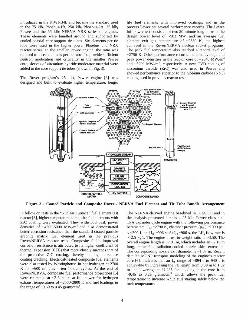
A Rover / NERVA-derived engine uses a “graphite matrix” material fuel element (FE) containing the U-235 fuel in the form of either coated particles of uranium carbide (UC2) or as a dispersion of uranium and zirconium carbide (UC-ZrC) within the matrix material, referred to as “composite” fuel (shown in Fig. 3). The basic FE [3] has a hexagonal cross section (~0.75” across the flats), is 52” long and produces ~1 MWt. Each FE has 19 axial coolant channels, which along with the element’s exterior surfaces, are coated with ZrC using chemical vapor deposition (CVD) to reduce hydrogen erosion of the graphite. This basic shape was
4
introduced in the KIWI-B4E and became the standard used in the 75 klbf Phoebus-1B, 250 klbf Phoebus-2A, 25 klbf Pewee and the 55 klbf NERVA NRX series of engines. These elements were bundled around and supported by cooled coaxial core support tie tubes. Six elements per tie tube were used in the higher power Phoebus and NRX reactor series. In the smaller Pewee engine, the ratio was reduced to three elements per tie tube. To provide sufficient neutron moderation and criticality in the smaller Pewee core, sleeves of zirconium hydride moderator material were added to the core support tie tubes (shown in Fig. 3). The Rover program’s 25 klbf Pewee engine [3] was designed and built to evaluate higher temperature, longer
life fuel elements with improved coatings, and in the process Pewee set several performance records. The Pewee full power test consisted of two 20-minute-long burns at the design power level of ~503 MWt and an average fuel element exit gas temperature of ~2550 K, the highest achieved in the Rover/NERVA nuclear rocket programs. The peak fuel temperature also reached a record level of ~2750 K. Other performance records included average and peak power densities in the reactor core of ~2340 MWt/m
3 and ~5200 MWt/m
3, respectively. A new CVD coating of zirconium carbide (ZrC) was also used in Pewee and showed performance superior to the niobium carbide (NbC) coating used in previous reactor tests.
Figure 3 - Coated Particle and Composite Rover / NERVA Fuel Element and Tie Tube Bundle Arrangement In follow on tests in the “Nuclear Furnace” fuel element test reactor [3], higher temperature composite fuel elements with ZrC coating were evaluated. They withstood peak power densities of ~4500-5000 MWt/m
3 and also demonstrated better corrosion resistance than the standard coated particle graphite matrix fuel element used in the previous Rover/NERVA reactor tests. Composite fuel’s improved corrosion resistance is attributed to its higher coefficient of thermal expansion (CTE) that more closely matches that of the protective ZrC coating, thereby helping to reduce coating cracking. Electrical-heated composite fuel elements were also tested by Westinghouse in hot hydrogen at 2700 K for ~600 minutes – ten 1-hour cycles. At the end of Rover/NERVA, composite fuel performance projections [5] were estimated at ~2-6 hours at full power for hydrogen exhaust temperatures of ~2500-2800 K and fuel loadings in the range of ~0.60 to 0.45 grams/cm3.
The NERVA-derived engine baselined in DRA 5.0 and in the analysis presented here is a 25 klbf Pewee-class dual TPA expander cycle engine with the following performance parameters: Tex ~2790 K, chamber pressure (pch ) ~1000 psi,
~300:1, and Isp ~906 s. At Isp ~906 s, the LH2 flow rate is ~12.5 kg/s. The engine thrust-to-weight ratio is ~3.50. The overall engine length is ~7.01 m, which includes an ~2.16 m long, retractable radiation-cooled nozzle skirt extension. The corresponding nozzle exit diameter is ~1.87 m. Recent detailed MCNP transport modeling of the engine’s reactor core [6], indicates that an Isp range of ~894 s to 940 s is achievable by increasing the FE length from 0.89 m to 1.32 m and lowering the U-235 fuel loading in the core from ~0.45 to 0.25 grams/cm3 which allows the peak fuel temperature to increase while still staying safely below the melt temperature.

5
The state-of-the-art for NTP can be summarized as follows: It is a proven technology! A high technology readiness level (TRL~5-6) was demonstrated during the Rover/NERVA programs (1955-1972) [3]. Twenty rocket reactors were designed, built and ground tested in integrated reactor / engine tests that demonstrated: (1) a wide range of thrust levels (~25, 50, 75 and 250 klbf); (2) high temperature carbide-based nuclear fuels that provided hydrogen exhaust temperatures up to 2550 K (achieved in the 25 klbf Pewee engine); (3) sustained engine operation (over 62 minutes for a single burn on the NRX-A6); as well as; (4) accumulated lifetime; and (5) restart capability (>2 hours during 28 startup and shutdown cycles on the NRX-XE experimental engine) – all the requirements necessary for a human mission to Mars.
3. FUEL OPTIONS AND NTP GROWTH
POTENTIAL
The NTR has significant “growth and evolution” potential not possible with chemical propulsion. For thermal and epithermal neutron energy spectrum reactor designs, one can transition from NERVA composite fuel to higher performance tricarbide fuels or to a fast neutron spectrum reactor using a ceramic-metal or “cermet” fuel. Cermet fuel was the primary backup option to the carbide-based fuels developed in Rover/NERVA. The fuel composition consists of uranium dioxide (UO2) fuel embedded in a high temperature tungsten (W) metal matrix. Cermet fuel underwent extensive nuclear/non-nuclear testing in the 1960’s under the GE-710 and Argonne National Laboratory (ANL) nuclear rocket programs [7,8] but no integrated reactor/engine tests were conducted. Fuel elements were designed and fabricated that were axial flow and hexagonal in geometry. A large number of fuel samples were produced and evaluated in a variety of separate effects tests. Non-nuclear, hot hydrogen exposure tests at temperatures up to 3000 K, including temperature cycling to demonstrate restart, established the viability of cermet fuel for NTP use. Irradiation tests, conducted under both transient and steady-state conditions, further indicated the fuel was robust and had the potential for high burn-up and improved fission product retention using a W-alloy cladding similar to the matrix material. Binary carbide fuels were produced at the end of the Rover/NERVA program and even higher temperature ternary or “tricarbide” fuel was developed in the former Soviet Union’s (FSU) nuclear rocket program that began after the Rover/NERVA program started and continued up until 1986. The FSU’s tricarbide fuel [9] consisted of a solid solution of uranium, zirconium and niobium carbide (UC-ZrC-NbC) having a maximum operating temperature of ~3200 K. The basic fuel element assembly was an axial flow design that contained a series of stacked 45 mm diameter bundles of thin (~1 mm) “twisted fuel ribbons” ~2 mm wide by ~100 mm long. The number of fuel bundles per assembly and the number of assemblies in the reactor core were determined by the desired engine thrust level and
associated power output. Although full-scale integrated engine tests were not conducted, hydrogen exhaust temperatures of ~3100 K for more than 1 hour were reported in reactor tests at the Semipalatinsk facility in Kazakhstan using bundled fuel elements individually fed with high pressure H2. Replacing NbC with higher melting point carbides like tungsten (WC), tantalum (TaC) or hafnium (HfC) could increase the maximum operating temperature beyond 3100 K allowing even higher specific impulse capability. Engine specific impulse versus hydrogen exhaust temperature for a 1000 psia chamber pressure and nozzle area ratios from 100:1 to 500:1 are shown in Fig. 4 for the various fuel types. The anticipated temperature range for coated particle, composite, cermet, binary and ternary carbides, and advanced tricarbides are also shown. These fuels can be operated at near maximum temperature or at lower temperature levels to extend fuel lifetime or to increase the engine’s operational margins. Besides providing high thrust and high Isp, the NTR also represents a “rich energy source” because it contains substantially more U-235 fuel in its reactor core than is consumed during the primary propulsion maneuvers performed in a typical human Mars mission. By recon-figuring the NTR for “bimodal” operation [9] (both thrust and power production), 10’s of kilowatts of electrical power (kWe) can be generated for crew life support, high data-rate communications, and zero-boiloff LH2 propellant storage using an active refrigeration system (shown in Fig. 5). With a more advanced “Second Generation” bimodal NTR (BNTR) system producing higher electrical power levels (~100’s kWe – 1 MWe), a “hybrid” bimodal nuclear thermal and electric propulsion (BNTEP) system is possible (Fig. 5) combining the benefits of both NTP (efficient, short planetary departure and capture maneuvers) and EP (efficient, sustained transfer through heliocentric space). In the “low tech” BNTR option without EP, the reactor supplies thermal energy for both propellant heating and modest electrical power generation. During the high thrust “propulsion phase”, 100’s of MWt are produced and removed using LH2 propellant pumped through the engine’s reactor core – like in the conventional NTR. During the “mission coast / power generation phase,” the BNTR’s reactor continues to operate but in an “idle mode” at greatly reduced thermal power levels (~125 kWt to produce ~25 kWe). Energy generated in the reactor fuel assemblies is removed using a secondary “closed” gas loop that carries a helium-xenon (He-Xe) gas mixture. In a NERVA-derived BNTR design, the existing regenerative-cooled core support tie tubes would carry the recirculated He-Xe coolant gas. Power from the NERVA fuel elements surrounding the tie tubes enters the tubes via conduction (see Fig. 3). In the fast reactor BNTR design called ESCORT [10], a closed loop, coaxial energy transport duct (ETD), integrated into each UO2 – W fuel element, carries the He-Xe coolant. The heated gas is then routed to a 25 kWe-class Brayton rotating

6
unit consisting of a turbine-alternator-compressor assembly that generates electricity at ~20% conversion efficiency. Waste heat is rejected to space using a conical pumped-loop radiator that is mounted to the exterior of the propulsion
stage thrust structure (Fig. 6). The radiator also helps remove low level decay heat power from the engines following high thrust operation.
Figure 4 - NTP Specific Impulse vs. Chamber Temperature for Different Fuels and Nozzle Area Ratios
Figure 5 - NTR Growth Paths: Bimodal Operation for Electricity with O2 Afterburner for Augmented Thrust
Because a BNTR-powered spacecraft generates its own “24/7” power, the need to deploy and operate large Sun-tracking photovoltaic arrays (PVAs) is eliminated. The configuration of the BNTR-powered MTV (long and linear) is also compatible with artificial gravity (AG) operations
[11,12]. By rotating the vehicle about its center-of-mass and
perpendicular to its flight vector, (illustrated at the bottom of Fig. 6), a centrifugal force and AG environment can be established to help maintain crew fitness during the transit out to Mars and back, also while in Mars orbit in the event of a surface accident requiring an “abort-to-orbit” [12].

7
Figure 6 - Artificial Gravity “Bimodal” NTR Crewed MTV with Conical Radiator on Aft Thrust Structure The performance and versatility of the basic NTR/BNTR engine can be further improved by adding an oxygen “afterburner” nozzle, storage and feed system to augment thrust and reduce the need for developing large, more costly engines. In the “LOX-augmented” NTR (LANTR) option [13,14], oxygen is injected into the divergent section of the nozzle downstream of the sonic throat (see Fig. 5). Here it mixes with reactor-heated H2 and undergoes supersonic combustion adding both mass and chemical energy to the rocket exhaust. By controlling the “oxygen-to-hydrogen” mixture ratio, the LANTR can operate over a wide range of thrust and Isp levels while the reactor core power level remains relatively constant. Downstream nozzle injection also isolates the reactor core from oxygen interaction and possible damage.
Transitioning to LANTR operation offers the potential for a number of engine, vehicle, and mission advantages [9] that include: (1) “big engine” performance from small engines to help reduce gravity losses; (2) shorter burn times to extend engine life; (3) reduced propellant tank size and mass resulting from the substitution of higher density LOX for lower density LH2; (4) reduced stage and vehicle size allowing deployment using smaller launch vehicles; and (5) increased operational range and payload delivery capability made possible by refueling with H2 and O2 propellants produced from extraterrestrial resources at strategic locations (shown in Fig. 7) as they become available. The NTR improvements outlined above offer the potential for significant downstream growth capability, well beyond that of chemical propulsion, and can lead to revolutionary performance advancements [14] in an evolutionary manner – “Revolution through Evolution”.
Figure 7 - Human Expansion Possibilities Using Bimodal LANTR-powered Space Transfer Vehicles

8
4. MISSION AND TRANSPORTATION SYSTEM
GROUND RULES AND ASSUMPTIONS
Specific mission and NTR transportation system ground rules and assumptions used in this paper are summarized in Tables 1 and 2, respectively. Table 1 provides information about the mission destinations, operational scenarios, and trip times along with assumed parking orbits at Earth, Mars, and Phobos. Trajectory details and representative V budgets for the “combined” minimum- and high-energy round trip ERV mission and the outbound high-energy crewed MTV mission are also provided. For the combined Mars/Phobos orbital reconnaissance mission analyzed, the NTR propulsion stage performs three short additional propulsive maneuvers (for plane change, periapse raising and apoapse lowering) required for the crewed MTV to rendezvous with Phobos.
Besides the large V requirements shown for the primary mission maneuvers [trans-Mars injection (TMI), Mars orbit capture (MOC) and trans-Earth injection (TEI)], additional smaller V maneuvers are needed for rendezvous and docking (R&D) of MTV components during the LEO assembly phase, for spacecraft attitude control during interplanetary coast, and for Mars orbital operations which include R&D of the ERV with the “spent” outbound crewed MTV’s payload element. For crewed missions, the outbound payload mass varies with crew size, mission destination and duration, and the type of auxiliary space excursion vehicle (SEV) selected. For missions exceeding ~1-year, additional consumables are carried in a consumables container mounted outside the primary TransHab module.
Table 1. Mission and Payload Ground Rules and Assumptions Mission Destinations / Profiles: • 2027 NEA 1991 JW (Mission trip time and V budget details provided on Fig. 11) • 2031 Mars Earth Return Vehicle (ERV) / Tanker mission (Outbound trip time: 283 days) • 2033 Crewed Mars mission (Round trip times: – 545 days/60 days in Mars orbit – 600 days/60 days in Mars orbit; includes 21 days at Phobos)
• NEA 1991 JW: “All-up” fully reusable round trip crewed mission • Split Mars mission: ERV pre-deployed to Mars ahead of crew • ERV mission uses “1-way” minimum energy outbound trajectory • Crewed mission uses higher energy “Opposition-class” trajectory (outbound transit times to Mars: 159 – 183 days) • ERV picks up crewed payload element; uses Venus swing-by on return leg (inbound transit times to Earth: 326 – 357 days) • Capsule recovery of crew at Earth for NEO and Mars missions
Earth, Mars, Phobos parking orbits • Earth: 407 km circular (LEO) • Mars: 250 km x 33,793 km • Phobos: 5981 km circular, equatorial
2031 ERV/Tanker Mars orbital mission V budgets
• Earth Departure C3 ~10.794 km2/s2, VTMI ~3.662 km/s, arrival Vinf ~3.480 km/s, VMOC ~1.341 km/s • For 326 day inbound transit: Mars Departure C3 ~36.48 km2/s2, VTEI ~3.12 km/s • For 357 day inbound transit: Mars Departure C3 ~35.88 km2/s2, VTEI ~3.08 km/s
2033 Opposition-class crewed Mars orbital mission V budgets: Crewed payload element transferred to ERV for return to Earth. For a Mars/Phobos orbital mission option, ~1105 m/s of additional V is assumed for rendezvous with and departure from Phobos
• For 159 day outbound transit: Earth Departure C3 ~14.62 km2/s2, VTMI ~3.83 km/s, arrival Vinf ~3.79 km/s, VMOC ~1.53 km/s • For 183 day outbound transit: Earth Departure C3 ~8.47 km2/s2, VTMI ~3.56 km/s, arrival Vinf ~3.702 km/s, VMOC ~1.47 km/s • NOTE: Gravity losses added to above Ideal Vs (value of g-loss depends on C3, vehicle T/W, Isp)
Additional V Requirements: Advanced material bipropellant rocket (AMBR) RCS thrusters used to perform non-primary propulsion maneuvers
• LEO R&D between orbital elements: ~100 m/s • Coast attitude control and mid-course correction: ~15 m/s and ~50 m/s, respectively • Mars orbit maintenance plus R&D: ~100 m/s
Crewed Mission Payload Mass: Varies with crew size; consumables based on mission duration and crew consumption rate of ~2.45 kg/person/day; payload also includes a short saddle truss (ST), second docking module (DM) and exterior consumables container. Auxiliary space excursion vehicle (SEV) options include a 1-person “ManCan” or a multi-crew SEV (MCSEV)
• Transit Habitat: 22.7 t – 27.5 t (minus consumables) • Short ST/DM/Container: 5.08 t / 1.76 t / 23% of stored food • Crew (4-6): 0.4 t – 0.6 t • Total Crew Consumables: 5.37 t in TransHab (~1-yr for 6 crew); with additional consumables stored in optional exterior container • SEV Options: 2 “ManCans” each @ 1 t or
Single MCSEV @ 6.7 t • CEV / SM: 10.0 t • Returned Samples: 0.1 t (NEO) – 0.25 t (Phobos)

9
The container, along with unneeded mass, can be jettisoned prior to the TEI maneuver to reduce propellant consumption. For the crewed NEO and Phobos missions analyzed, it is assumed that the crew will collect and return ~100 kg and 250 kg of samples, respectively. Table 2 lists the key transportation system ground rules and assumptions. The NTR engine and fuel type, thrust level and operating characteristics are summarized first. The 25 klbf NTR engine design baselined here uses composite fuel and a U-235 fuel loading of 0.25 g/cm3. With a hydrogen exhaust temperature (Tex) of ~2790 K, and a nozzle area expansion ratio of ~300:1, the Isp is ~906 s with higher Isp values achievable by increasing the fuel operating
temperature. The total LH2 propellant loading for a Mars mission consists of the usable propellant plus performance reserve, post-burn engine cooldown, and tank trapped residuals. For the smaller auxiliary maneuvers, a storable bipropellant RCS system is used. The LH2 propellant used in the ERV and outbound crewed MTVs is stored in the same “state-of-the-art” Al/Li LH2 propellant tank that would be developed for the HLV and used for future human exploration missions. For this analysis, tank sizing assumes a 30 psi ullage pressure, 5 gE axial / 2.5 gE lateral launch loads, and a safety factor of 1.5. A 3% ullage factor is also assumed. All tanks use a combination foam / multilayer insulation (MLI) system for
Table 2. NTR Transportation System Ground Rules and Assumptions
NTR System Characteristics • Engine/Fuel Type: NERVA-derived/UC-ZrC in graphite “Composite” fuel • Propellant: LH2 • Thrust Level: 25 klbf Pewee-class engine (3 engine cluster on “Core” Propulsion Stage) • Fuel Element Length: 0.89 m – 1.32 m; 1.32 m is the baseline • Exhaust Temp: Tex 2731 – 2940 K • Chamber Pressure: pch 1000 psi • Nozzle Area Ratio: 300:1 • Isp Range: 906 s (2790 K) – 941 s (2940 K)
Propellant Margins • Cooldown: • Performance reserve: • Tank trapped residuals:
3% of usable LH2 propellant 1% on V 2% of total tank capacity
Reaction Control System (for LEO R&D, Attitude Coast Control, and Mid-course Correction Burns)
• Propulsion Type: • Propellant: • Nominal Isp:
AMBR 200 lbf thrusters NTO/MMH 335 seconds
LH2 Cryogenic Tanks and Passive Thermal Protection System (TPS)
• Material: Aluminum-Lithium (Al/Li) • Tank ID/OD: ~9.8 m/10.0 m • Tank L: ~19.7 m (propulsion stage) – 22.7 m (“in-line” drop tank) • Geometry: cylindrical with root 2/2 ellipsoidal domes • Insulation: 1” SOFI (~0.78 kg/m2) + 60 layers of MLI (~0.90 kg/m2)
Active Cryo-Fluid Management/Zero Boil-Off (ZBO) LH2 Propellant System
• ZBO Brayton-cycle cryocooler system powered by PVAs • ZBO mass and power requirements for NTR core stage are 930 kg and ~8.87 kWe, respectively
Photovoltaic Array (PVA) Primary Power System
• PVA sized for ~7 kWe at 1 A.U., PVA mass and area are ~455 kg and ~25 m2, respectively; to supply 1 kWe at Mars requires ~10 m2
of array area • “Keep-alive” power supplied by nickel-hydride battery system
Dry Weight Contingency Factors • 30% on NTR system and composite structures • 15% on established propulsion, propellant tanks, spacecraft systems
HLV Launch Requirements: – Lift Capability to LEO – Launch Shroud Size – Cylindrical Payload (PL) Envelope
• ~139 t; NTR propulsion stage with external crew radiation shields • 12 m D x 42.5 m L • 10 m D x 33.5 m L (crewed mission PL element)

10
passive thermal protection. A zero boil-off (ZBO) “Brayton-cycle” cryocooler system is used on each NTR propulsion module LH2 tank to eliminate boiloff during LEO assembly and during the long duration NEO and Mars orbital missions. The propellant tank heat load is largest in LEO and sizes the ZBO cryocooler system. Solar photovoltaic arrays supply the needed primary electrical power for the MTV systems.
Because of the decreased solar intensity at Mars (~486 W/m2), array areas can become quite large (~10 m2/kWe) necessitating multiple arrays. Table 2 also provides the assumed “dry weight contingency” (DWC) factors, along with HLV lift and shroud payload envelope requirements. A 30% DWC is used on the NTR system and advanced composite structures (e.g., stage adaptors, trusses) and 15% on heritage systems (e.g., Al/Li tanks, RCS, etc.).
Figure 8 - NTR “Core” Stage Sizing: Fixed Stage Length and Increasing Tank Diameter
In 1991, the Synthesis Group [15] identified heavy lift launch capability as a basic necessity for efficiently under-taking human Moon / Mars exploration. A “minimum lift” of ~150 t and a large cylindrical payload envelope (~10 m D x ~30 m L) was recommended to reduce launch count and simplify vehicle assembly in LEO. Similar increases were used in the “7-Launch” NTR Mars mission strategy for DRA 5.0. Figure 8 shows the variation in propellant loading and NTR stage launch mass with increasing tank diameter. For a fixed total stage length of ~32.2 m (~30 m with the clustered 25 klbf NTR engine nozzles retracted for launch) and other specified stage lengths, the maximum available
LH2 tank length (L) is ~19.7 m. By enlarging the stage tank diameter (D) from 8.4 m to 10 m, the LH2 propellant loading and total stage mass increase by ~40% and ~27%, respectively. The crewed payload element for DRA 5.0 [4] determined the HLV shroud size. It included the “packaged” TransHab module, short saddle truss, consumables container, secondary docking module and Crew Entry Vehicle (CEV) / Service Module (SM) and had a maximum OD of ~11 m and a total length of ~33.8 m. The 10 m D propulsion stage mass (shown in Fig. 8) provided the ~140 t lift requirement although smaller stages with lower lift requirements are possible.

11
5. MARS DRA 5.0: “7-LAUNCH” NTR MISSION OVERVIEW
The 7-Launch NTR Mars mission strategy [4] for a human landing mission is illustrated in Fig. 9 and is centered around the long surface stay, split cargo / piloted mission approach. Two cargo flights are used to pre-deploy a cargo lander to the surface and a habitat lander into Mars orbit where it remains until the arrival of the crew on the next mission opportunity (~26 months later). The cargo flights utilize “1-way” minimum energy, long transit time trajectories. Four HLV flights carried out over 90 days (~30 days between launches), deliver the required components for the two cargo vehicles. The first two launches deliver the NTR core propulsion stages each with three 25 klbf NTR engines. The next two launches deliver the cargo and habitat lander payload elements which are enclosed within a large triconic-shaped aeroshell that functions as payload shroud during launch, then as an aerobrake and thermal protection system during Mars aerocapture (AC) and subsequent entry, descent and landing (EDL) on Mars. Vehicle assembly involves Earth orbit rendezvous and docking (R&D)
between the propulsion stages and payload elements with the NTR stages functioning as the active element in the R&D maneuver. Once the operational functions of the orbiting habitat and surface cargo landers are verified, and the Mars Ascent Vehicle (MAV) is supplied with ISRU-produced ascent propellant, the crewed MTV is readied and departs on the next mission opportunity. The all-propulsive crewed MTV is a “0-gE” vehicle design that utilizes a fast conjunction trajectory that allows ~6 month “1-way” transit times to and from Mars. Like the cargo MTV, it is an “in-line” configuration that uses Earth orbit R&D to simplify vehicle assembly. It uses the same “common” NTR propulsion module but includes additional external radiation shielding on each engine for crew protection during engine operation. Three HLV launches over 60 days are used to deliver the vehicle’s key components which include: (1) the NTR propulsion stage; (2) integrated “saddle truss” and LH2 drop tank assembly; and (3) supporting crewed payload. The crewed payload component includes the TransHab module
Figure 9 - DRA 5.0 Long-Stay Mars Mission Overview: “7-Launch” NTR Strategy
with its six crew, a long-lived CEV/SM for vehicle-to-vehicle transfer and “end of mission” Earth entry, a secondary T-shaped docking module (DM), contingency consumables container and connecting structure. Four 12.5 kWe / 125 m2 rectangular PVAs provide the crewed MTV with ~50 kWe of electrical power at Mars for crew life-support (~30 kWe), ZBO cryocoolers (~10 kWe), and high
data-rate communications (~10 kWe) with Earth. When assembly is complete, the crew launch vehicle (CLV) delivers the Mars crew. The CEV/SM docks on the underside of the orbiting MTV using the secondary DM that connects the TransHab crew module and contingency consumables container (shown below in Fig. 10).

12
Figure 10 - Key Features and Component Lengths of the Crewed NTR Mars Transfer Vehicle
Following the TMI maneuver, the drained LH2 drop tank, attached to the central saddle truss, is jettisoned and the crewed MTV coasts to Mars under 0-gE conditions and with its four PVAs tracking the Sun. Attitude control, mid-course correction and vehicle orientation maneuvers are provided by a split RCS with thrusters and bipropellant located on the rear NTR propulsion module and the short saddle truss forward adaptor ring just behind the TransHab module. After propulsively capturing into Mars orbit, the crewed MTV rendezvouses with the orbiting Hab lander using engine cooldown thrust and the vehicle’s RCS. The crew then transfers over to the lander using the CEV/SM that subsequently returns and docks to the TransHab autono-mously. The crew then initiates EDL near the cargo lander and begins the surface exploration phase of the mission. After ~533 days on the surface, the crew lifts off and returns to the MTV using the MAV. Following the transfer of the crew and samples to the MTV, the MAV is jettisoned. The crew then begins a weeklong checkout and verification of all MTV systems, jettisons the DM and contingency consumables and performs the TEI burn to begin the journey back to Earth. After an ~6 month trip time, the crew enters the CEV/SM, separates from the MTV and
subsequently re-enters the atmosphere while the MTV flies by Earth at a “sufficiently high altitude” and is disposed of into heliocentric space. The “Copernicus” crewed MTV has an overall length is ~93.7 m and an IMLEO of ~336.5 t consisting of: (1) the NTR propulsion stage (~138.1 t); (2) the saddle truss and LH2 drop tank (133.4 t); and (3) the crew payload section (~65 t). The propulsion module (PM) uses a three-engine cluster of 25 klbf NTR engines and also carries additional external radiation shield mass (~7.3 t) for crew protection. The PM’s Al/Li LH2 tank size and propellant capacity are 10 m D x 19.7 m L and ~87.2 t, respectively. It also carries avionics, RCS, auxiliary battery and PVA power, docking and Brayton-cycle ZBO refrigeration systems located in the forward cylindrical adaptor section. To remove ~78 watts of heat penetrating the 60 layer MLI system in LEO (where the highest tank heat flux occurs), the Brayton cryocooler system needs ~8.9 kWe for its operation (~114 We for each Wt removed). Twin circular PVAs on the PM provide the electrical power for the ZBO system in LEO until the four primary PVAs on the crewed PL section are deployed prior to TMI.

13
The second major component is the saddle truss and LH2 drop tank assembly. The saddle truss is a rigid, spine-like composite structure that wraps around the upper half of the LH2 drop tank and connects the core PM to the forward payload section. It is ~27.7 m long and has a mass of ~9 t. The saddle truss is open underneath allowing the drained LH2 drop tank to be jettisoned after the TMI burn is completed. The ~22.7 m long LH2 drop tank has a mass of ~22 t and carries ~102.4 t of propellant. Copernicus’ third and final component is its payload section that is designed for launch as a single integrated unit and determines the overall shroud size discussed above. The integrated payload element is ~33.8 m long and includes a short saddle truss with a “T-shaped” docking module (DM) and transfer tunnel connecting the TransHab module to the jettisonable contingency consumables container (shown in Fig. 10). The second DM also provides docking access for the crew delivery CEV/SM and the MAV. Following the crew’s return from Mars and MAV separation, the DM and attached consumables container are both jettisoned to reduce vehicle mass prior to TEI (see Fig. 9). The total crewed payload mass at TMI is ~65 t distributed as follows: (1) short saddle truss (~5.1 t); (2) second DM and transfer tunnel (~1.8 t); (3) contingency consumables and jettisonable container (~9.7 t); (4) TransHab with its primary PVAs (~27.5 t); (5) transit consumables (~5.3 t); (6) crew (~0.6 t); (7) long-lived CEV/SM (~10 t); and (8) forward RCS and propellant (~5 t). The crewed MTV’s total RCS propellant loading is ~9.1 t with the “post-TMI” RCS propellant load split between the core stage (~5.1 t) and the
short saddle truss forward cylindrical adaptor ring (~4 t). Lastly, for DRA 5.0, the performance requirements on operating time and restart for Copernicus’ 3 – 25 klbf NTR engines are quite reasonable. For the round trip mission, there are 4 primary burns (3 restarts) that use ~178.4 t of LH2 propellant. With 75 klbf of total thrust and a Isp of 906 s the total engine burn time for the mission is ~79.2 minutes (~55 minutes for the “2-perigee” TMI burns, ~14.5 minutes for MOC, and ~9.7 minutes for TEI), well under the ~2 hour accumulated engine burn time and 27 restarts demonstrated by the NERVA eXperimental Engine (the NRX-XE) in 1969.
6. USE OF COPERNICUS AND ITS COMPONENTS
FOR NEO AND MARS / PHOBOS ORBITAL
MISSIONS
Reusable Crewed Asteroid Survey Mission to NEA 1991 JW The performance capability of Copernicus has been evaluated for a number of candidate NEO missions currently under study by NASA. Summarized here are results for a reusable “1-year” round trip mission to near Earth asteroid (NEA) 1991 JW, an L-type asteroid with a diameter of ~490 m. The trajectory and the V budget details for this reusable 2027 mission are shown in Fig. 11. The total mission V requirement and round trip time are ~7.2 km/s and 362 days, respectively. The mission has an outbound transit time of 112 days, a 30-day stay at 1991 JW and an inbound transit time of 220 days.
Figure 11 - Trajectory and Vehicle Details for Reusable NTR Asteroid Survey Mission to NEA 1991 JW
14
Outfitted as an Asteroid Survey Vehicle (ASV), a less demanding NEO reconnaissance mission can serve as a “check out” mission for Copernicus’ key elements (its propulsion module, TransHab and life support systems, etc.) in a “deep space” environment prior to undertaking a longer duration Mars orbital mission. The Apollo 8 orbital mission of the Moon in December 1968 provided a similar check out for the Apollo Command and Service module and its primary propulsion system. A 1-year round trip mission time is also comparable to the Venus swing-by leg of a short round trip, short orbital stay Mars mission and is within the current Russian and US astronaut experience base in 0-gE on Mir and the ISS. Finally, such a mission can also provide valuable scientific data on asteroid composition plus experience in proximity operations needed for extracting future resources or for executing potential threat mitigation techniques against a possible Earth impacting NEO. The ASV “Searcher” (shown in Fig. 11) has an IMLEO of ~316.7 t comprising the NTR propulsion module (~137.7 t), the saddle truss and ~21.1 m long LH2 drop tank (~116.7 t), and the crew PL section (~62.3 t). The PL element includes the TransHab (27.5 t), consumables (5.4 t) for 6 crew (0.6 t), the CEV/SM (10 t) used for crew re-entry, the short saddle truss (~5.1 t) and DM / transfer tunnel (~1.8 t) connecting the TransHab to the MCSEV, plus the forward RCS (~5.2 t). The MCSEV (~6.7 t) is used for close-up examination and sample gathering and is returned to Earth along with 100 kg of samples. The total LH2 propellant loading for the mission
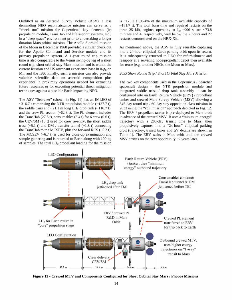
is ~175.2 t (96.4% of the maximum available capacity of ~181.7 t). The total burn time and required restarts on the three 25 klbf engines operating at Isp ~906 s, are ~73.8 minutes and 4, respectively, well below the 2 hours and 27 restarts demonstrated on the NRX-XE. As mentioned above, the ASV is fully reusable capturing into a 24-hour elliptical Earth parking orbit upon its return. It is subsequently returned to LEO for refurbishment and resupply at a servicing node/propellant depot then available for reuse (e.g. to other NEOs, the Moon or Mars). 2033 Short Round Trip / Short Orbital Stay Mars Mission The two key components used in the Copernicus / Searcher spacecraft design – the NTR propulsion module and integrated saddle truss / drop tank assembly – can be configured into an Earth Return Vehicle (ERV) / propellant tanker and crewed Mars Survey Vehicle (MSV) allowing a 545-day round trip / 60-day stay opposition-class mission in 2033 using the “split mission” approach depicted in Fig. 12. The ERV / propellant tanker is pre-deployed to Mars orbit in advance of the crewed MSV. It uses a “minimum-energy” trajectory with a 283-day transit time to Mars, then propulsively captures into a “24-hour” elliptical parking orbit (trajectory, transit times and V details are shown in Table 1). The ERV waits in Mars orbit until the crewed MSV arrives on the next opportunity ~2 years later.
Figure 12 - Crewed MTV and Components Configured for Short Orbital Stay Mars / Phobos Missions

15
The crewed MSV uses a higher energy “1-way” transit out to Mars taking ~159 days and propulsively captures into the same Mars parking orbit as the ERV. In the process, the crewed MSV uses a substantial percentage of the vehicle’s available propellant. To return to Earth, the 6-crew MSV rendezvouses with the ERV and the forward crewed PL element is switched over to the ERV (shown in Fig. 13). No propellant transfer is required just a R&D maneuver. Before
the ERV performs the TEI maneuver, the exterior consumables container and connecting tunnel (~6.2 t) are jettisoned from the PL element to reduce propellant consumption. The ERV utilizes an inbound Venus swing-by on the 326-day transfer back to Earth. At mission end, the crew re-enters in the CEV capsule, while the MSV flies by Earth and is disposed of into heliocentric space.
Figure 13 - “Switch-over” - Crewed PL Element Transfer to ERV in Mars Orbit for Trip Back to Earth
The outbound crewed MSV has an IMLEO of ~251.1 t consisting of NTR propulsion module (~107 t), the integrated saddle truss / LH2 drop tank assembly (~84.3 t), and the crewed PL element (~59.8 t). The PM and ~21.1 m long LH2 drop tank are substantially off-loaded in propellant (~ 66.8% and 59.6%, respectively), with ~114.5 t of LH2 propellant carried on the outbound crew mission (~63% of the maximum available capacity of ~181.7 t). In addition to 3 restarts, the total burn time on the MSV’s three 25 klbf engines is ~47.7 minutes, substantially lower than that needed for DRA 5.0 and the reusable NEO mission to 1991 JW discussed above, and well below the capabilities demonstrated on the NRX-XE. The “round trip” ERV / tanker has an IMLEO of ~237.4 t consisting of NTR propulsion module (~127.6 t) and the integrated saddle truss / LH2 drop tank assembly (~109.8 t). The ERV carries a larger total LH2 propellant loading in its propulsion stage and forward drop tank totaling ~153.6 t (~84.5% of the maximum available capacity of ~181.7 t) which is needed to return the crewed PL back to Earth. In addition to 3 restarts, the total burn time on the ERV’s three 25 klbf engines is ~64.2 minutes (~35.2 minutes total for the “2-perigee” TMI burn, ~7.9 minutes for MOC, and ~21.1 minutes for TEI), again well below the capabilities demonstrated on the NRX-XE. The ERV’s longer TEI burn duration is attributed to the addition of the ~51.2 t crewed PL plus the higher TEI V requirement (~3.12 km/s versus
~1.56 km/s for DRA 5.0). Lastly, the total mission IMLEO for the outbound crewed MSV and the ERV is ~488.5 t. 2033 Combined Mars and Phobos Orbital Mission Option The capabilities of the Copernicus / Searcher spacecraft design can be extended further to include a combined orbital reconnaissance mission of Mars and its moon, Phobos (shown in Fig. 14), by reducing the crew size to 4 and extending the mission round trip time to 600 days (183 days outbound, 60 days at Mars / Phobos, and 357 days inbound) as detailed in Table 1. As before, the mission would begin with the ERV / tanker departing LEO in December 2030 on a 283-day, minimum-energy trajectory to Mars then propulsively capturing into a 24-hour elliptical Mars parking orbit in October 2031. The crewed mission follows with the outbound MSV departing LEO in April 2033 and propulsively capturing into the same 24-hour elliptical Mars parking orbit in October 2033, 183 days later. The crewed MSV has an IMLEO of ~312.1 t consisting of the NTR propulsion module (~136.6 t), the integrated saddle truss / drop tank assembly (~119.2 t), plus the crewed PL section (~56.2 t). The later includes the smaller TransHab (22.7 t), 4 crew (0.4 t), consumables (~6 t), the short saddle truss (~5.1 t), and the transfer tunnel (~1.8 t) connecting the TransHab to the exterior consumables container (~0.5 t) plus the forward RCS (~6.2 t). Also included is a “3-port”

16
Figure 14 - Combined Mars / Phobos Orbital Mission is Possible Using NTR Crewed MSV and ERV
docking module (1.5 t) located at the front of the TransHab that accommodates the CEV/SM (10 t) plus two 1-person “ManCans” (2 t) used for up-close inspection and sample collection at Phobos (shown in Fig. 14 insert). After ~30 days of Mars orbital reconnaissance, the crewed MSV performs three short propulsive maneuvers (for plane change, periapse raising and apoapse lowering totaling ~1105 m/s of extra V) necessary to rendezvous with Phobos which has an ~6000 km circular equatorial orbit about Mars. Over the next 3 weeks the crew explores Phobos using the 2 ManCans to collect ~250 kg of samples. The crew then jettisons waste and unneeded payload mass (~6.8 t) and returns to its original 24-hour elliptical parking orbit (requiring an additional ~1105 m/s of V). Here the remaining crewed PL element (~46.3 t) and Phobos samples are transferred to the waiting ERV for the return to Earth. The combined Mars/Phobos mission outlined above is the most challenging for a Copernicus/Searcher-class spacecraft requiring a total LH2 propellant loading of ~177.4 t (~97.6% of Copernicus’ maximum available capacity of ~181.7 t). The total engine burn time is ~74.4 minutes and there are 8 engine restarts, with 6 of these associated with the “3-burn” Phobos rendezvous and departure maneuver sequence. The ERV has an IMLEO of ~236 t consisting of the NTR propulsion module (~126.7 t) and the integrated saddle truss / LH2 drop tank assembly (~109.3 t). The total LH2 propellant load for the round trip ERV mission is ~151.8 t (~83.6% of the maximum available capacity of ~181.7 t). The total engine burn time is ~63.4 minutes and 3 restarts are required. For the combined Mars/Phobos orbital mission, the total IMLEO for the outbound crewed MTV and the ERV is ~548.1 t.
7. PLANS FOR NTP TECHNOLOGY
DEVELOPMENT AND DEMONSTRATION
In FY’11, NASA restarted a NTP technology development and demonstration effort under the Advanced In-Space Propulsion (AISP) component of its Exploration Technology Development and Demonstration (ETDD) program. The NTP effort included two key tracks – “Foundational Technology Development” followed by “Technology Demonstration” projects (shown in Fig. 15). Near-term NTP activities initiated under Foundational Technology Development, which are now part of NASA’s new Nuclear Cryogenic Propulsion Stage (NCPS) project, included five key tasks and objectives: Task 1. Mission Analysis, Engine/Stage System Characteri-zation and Requirements Definition to help guide initial foundational technology work, and the subsequent development of small ground and flight technology demonstration engines scalable to the full size engines required for future human NEO and Mars exploration missions; Task 2. NTP Fuels and Coatings Assessment and Techno-logy Development aimed at recapturing fabrication techniques, maturing and testing fuel, then selecting between the two primary fuel forms previously identified by DOE and NASA [16] – NERVA “composite” and UO2 in tungsten “cermet” fuel. Samples and candidate coatings will be produced initially followed by partial-length, then full-length fuel elements. The NTR Element Environmental Simulator (NTREES) [17] at the MSFC will provide up to ~1.2 MW of RF heating to simulate the NTP thermal environment that includes exposure to hot H2. NTREES will be used to screen candidate fuels and fuel element designs prior to irradiation testing and final selections;

17
Figure 15 - NTP Development Plan includes Foundational, Ground and Flight Technology Demonstrations Task 3. Engine Conceptual Design, Analysis, and Modeling aimed at developing conceptual designs of small demonstration engines and the full size 25 klbf-class engines utilizing the candidate fuels discussed above. State-of-the-art numerical models will be used to determine reactor core criticality, detailed energy deposition and control rod worth within the reactor subsystem [18], provide thermal, fluid and stress analysis of fuel element geometries [19], and predict engine operating characteristics and overall mass [20]; Task 4. Demonstration of Affordable Ground Testing focused on “proof-of-concept” validation of the SAFE (Subsurface Active Filtration of Exhaust) [21] or “bore-hole” test option at the Nevada Test Site (NTS). Non-nuclear, subscale hot gas injection tests, some with a radioactive tracer gas (Krypton-85), will be conducted in existing vertical bore-holes to obtain valuable test data on the effectiveness of the porous rock (alluvium) to capture, holdup and filter the engine exhaust. The data will also help calibrate design codes needed by DOE to design the SAFE test facility and support infrastructure needed for the small ground and flight technology demonstration engine tests and the larger 25 klbf-class engine tests to follow; and
Task 5. Formulation of an Affordable and Sustainable NTP Development Strategy which outlines a plan that utilizes separate effects tests (e.g., NTREES and irradiation tests), innovative SAFE ground testing at the Nevada Test Site, plus the use of a small scalable engine for ground then flight technology demonstrations. The results from the above tasks will provide the basis for “authority to proceed” (ATP) in ~2015 with ground technology demonstration (GTD) tests at the NTS in late 2019, followed by a flight technology demonstration (FTD) mission in 2023. In order to reduce development costs, the GTD and FTD tests will use a smaller, lower thrust (~5 – 7.5 klbf) engine that is based on a “common” fuel element design that is scalable to the desired higher thrust engines by increasing the number of elements in a larger diameter core that can produce greater thermal power output. The GTD project will build and test two ground test articles (GTA1, GTA2) and one flight test article (FTA) that provides system technology demonstration and design validation for a follow-on FTD mission. The small engine can be used individually for small robotic science missions, or arranged

18
in a 2 – 3 engine cluster for higher payload missions. The FTD will also provide the technical foundation for an “accelerated approach” to design, fabrication, ground then flight testing of the larger 25 klbf-class engine by ~2026. The Rover program used a common fuel element/tie tube design and similar approach to test the 50 klbf Kiwi-B4E, the 75 klbf Phoebus-1B, the 250 klbf Phoebus-2A, and 25 klbf Pewee engines, in that order, between 1964 and 1968. Flight testing a NTR propulsion stage with clustered 25 klbf engines would follow next in time to support 1-year round trip human NEO missions in the late 2020’s and short round trip / short orbital stay Mars missions using the “split cargo and crew” mission approach outlined above in the early 2030’s.
8. SUMMARY AND CONCLUSIONS
The NTR represents the next major evolutionary step in high performance liquid rocket engines yet it is not new but was developed to a high technology readiness level during the Rover/NERVA programs. In twenty reactor tests, a wide range of thrust levels were demonstrated, along with high-temperature coated particle and composite fuel, sustained engine operation, accumulated time at full power, and restart capability – everything required for a human mission to Mars. Important developmental work on UO2 – W cermet fuel, the backup to the carbide-based fuels developed in Rover/NERVA, was also conducted during the ANL and GE-710 programs, and even higher temperature UC-ZrC-NbC ternary carbide fuels were developed in the Russian NTP program. Besides the use of higher temperature nuclear fuels, NTP has additional “evolution and growth” potential. Configured as a “bimodal” system, the BNTR can generate its own electrical power eliminating the need for deploying and operating large Sun-tracking PVAs. The configuration of a BNTR-powered MTV (long and linear) has other attractive features as well. By rotating the vehicle about its center-of-mass and perpendicular to its flight vector, a centrifugal force and AG environment can be established to help maintain crew fitness on long duration space flights. The addition of an oxygen “afterburner” nozzle and propellant feed system in the LANTR option provides a further NTR enhancement that allows a variable thrust and Isp capability, bipropellant operation plus the ability to utilize extra-terrestrial sources of hydrogen and oxygen that exist throughout the Solar System. These improvements to the basic NTR can lead to revolutionary performance advancements in an evolutionary manner – “Revolution through Evolution”. As mentioned previously, NTP was selected as the preferred propulsion option in NASA’s recent Mars DRA 5.0 study. With its high thrust and “factor of 2” higher specific impulse over chemical propulsion, the use of NTP helped reduce the required launch mass for DRA 5.0 by over 400 t
– the equivalent mass of the International Space Station. Another important consideration was its demonstrated capability. It is the only advanced propulsion technology tested at the performance levels required for a human Mars mission and requires no large technology or performance scale-ups. In fact, the smallest engine tested during the Rover program – the 25 klbf “Pewee” engine is sufficient when used in a clustered engine arrangement. The Copernicus crewed MTV design developed for DRA 5.0 has 2 key elements – a common propulsion module with three 25 klbf “Pewee-class” NTR engines and an integrated “saddle truss” and LH2 propellant drop tank assembly that connects the payload and propulsion elements. Because the Copernicus spacecraft is sized to allow it to perform all of the fast-conjunction missions over the 15-year synodic cycle, it has significant capability that can be utilized for NEO and Mars orbital missions currently under consideration by NASA. A human exploration and technology development strategy is outlined that uses the basic Copernicus vehicle to perform a reusable 1-year round trip mission to NEA 1991 JW in the late 2020’s to check out vehicle systems. Afterwards, the Copernicus spacecraft and its 2 key components, now configured as an Earth Return Vehicle / propellant tanker, would be used for a short round trip (18 – 20 months) / short orbital stay (60 days) Mars missions in 2033 using the split mission approach. Also noteworthy is the fact that the total engine operating time and required restarts for all missions analyzed are well below the capabilities demonstrated on the NRX-XE ~43 years ago! Finally, and most importantly, NASA restarted an NTP technology development and demonstration effort in FY’11 that includes Foundational Technology Development work in the five key task areas discussed above. The results from these tasks will provide the basis for continuing work in these same areas under the Nuclear Cryogenic Propulsion Stage (NCPS) project in FY’s 12 – 14. This effort will be followed by system-level Technology Demonstrations that include ground testing a small, scalable NTR before 2020, with a flight test shortly thereafter.
Acknowledgments The authors express their thanks to Chris Moore and John Warren (NASA/HQ), Bret Drake (JSC), former ESMD Associate Administrator Doug Cooke (retired), as well as John Taylor and Tim Wickenheiser (GRC) for their support of this work. The author (SKB) also expresses his thanks to Bob Sauls (John Frassanito & Associates, Inc.) for artwork commissioned by GRC and depicted in Figs. 1, 6, 11, 13 and 14.

19
REFERENCES
[1] National Space Policy of the United States, June 28, 2010, pg.11. [2] Human Exploration of Mars Design Reference Architecture 5.0, Drake, Bret G., ed., National Aeronautics and Space Administration, NASA-SP- 2009-566, Washington, DC, July 2009. [3] Koeing, D. R., “Experience Gained from the Space Nuclear Rocket Programs (Rover/NERVA),” Los Alamos National Laboratory, Report LA-10062-H, Los Alamos, NM, May 1986. [4] Borowski, Stanley K., McCurdy, David R., and Packard, Thomas W., “7-Launch NTR Space Transportation System for NASA’s Mars Design Reference Architecture (DRA) 5.0”, AIAA-2009-5308, August 2009. [5] Taub, J. M., “A Review of Fuel Element Development for Nuclear Rocket Engines”, Los Alamos National Laboratory, Report LA-5931, Los Alamos, NM, June 1975. [6] Schnitzler, Bruce G., Borowski, Stanley K., and Fittje, James E., “25,000-lbf Thrust Engine Options Based on the Small Nuclear Rocket Engine Design”, AIAA-2009- 5239, August 2009. [7] General Electric, “710 High-Temperature Gas Reactor Program Summary Report: Volume III-Fuel Element Development”, GEMP-600-V3, 1968. [8] Bhattacharyya, S. K., “An Assessment of Fuels for Nuclear Thermal Propulsion”, Argonne National Laboratory, Report ANL/TD/TM01-22, Argonne, IL, Dec. 2001. [9] Borowski, Stanley K., Dudzinski, Leonard A., and McGuire, Melissa L., “Vehicle and Mission Design Options for the Human Exploration of Mars/Phobos Using Bimodal NTR and LANTR Propulsion”, AIAA- 98-3883, July 1998 and NASA/TM-1998-208834/Rev1. [10] Joyner, Claude R., “The Synergistic Application of Chemical Rocket Component Technologies to the ESCORT Nuclear Bimodal System”, AIAA-2000- 3211, July, 2000. [11] Borowski, Stanley K., Dudzinski, Leonard A., and McGuire, Melissa L., “Artificial Gravity Vehicle Design Option for NASA’s Human Mars Mission Using Bimodal NTR Propulsion”, AIAA-99-2545,
[12] Borowski, Stanley K., Dudzinski, Leonard A., and McGuire, Melissa L., “Bimodal Nuclear Thermal Rocket (NTR) Propulsion for Power-Rich, Artificial Gravity Human Exploration Missions to Mars”, IAA- 01-IAA.13.3.05, 52nd International Astronautical Congress, Toulouse, France, October 2001. [13] Bulman, M. J., Messitt, D. G., Neill, T. M., and Borowski, S. K., “Continued LOX-Augmented Nuclear Thermal Rocket (LANTR) Testing”, AIAA- 2002-3650, July 2002. [14] Borowski, S. K. and Dudzinski, L. A., “2001: A Space Odyssey Revisited – The Feasibility of 24 Hour Commuter Flights to the Moon Using NTR Propulsion with LUNOX Afterburners”, AIAA-97-2956, July 1997 and NASA/TM – 1998-208830/Rev1. [15] America at the Threshold – America’s Space Exploration Initiative”, Report of the Synthesis Group, Available from the Superintendent of Documents, U. S. Government Printing Office, Washington, DC 20402, June 1991. [16] Burkes, D. Wachs, D., Werner, J., (DOE/INL), Bell, G., Miller, J., Papano, P., (DOE/ORNL), and Borowski, S. K., (NASA/GRC), “The Rationale and Justification for Selection of Carbide “Composite” and Ceramic Metallic “Cermet” NTP Fuel Options”, a Joint DOE / NASA White Paper for NASA HQ, May 2007. [17] Emrich, William J., and Kirk, Daniel R., “Design Considerations for the Nuclear Thermal Rocket Element Environmental Simulator (NTREES)”, AIAA- 2006-5270, July 2006. [18] Schnitzler, Bruce G., and Borowski, Stanley K., “Neutronics Models and Analysis of Small Nuclear Rocket Engine (SNRE)”, AIAA-2007-5618, July 2007. [19] Stewart, Mark E., and Schnitzler, Bruce G., “Thermal Hydraulic Simulations of NTP Reactor Core”, AIAA- 2007-5619, July 2007. [20] Fittje, James E., “Upgrades to the NESS (Nuclear Engine System Simulation) Code”, AIAA-2007-5620, July 2007. [21] Howe, Steven D., Travis, B., and Zerkle, D.K., “SAFE Testing of Nuclear Rockets”, Journal of Propulsion and Power, Vol. 17, No. 3, pg. 534-539 (2001).
June 1999.

20
BIOGRAPHIES
Dr. Stan Borowski is a senior aerospace / nuclear engineer and branch chief of the Propulsion & Controls Systems Analysis group at NASA’s Glenn Research Center (GRC). During his past 23 years, he has been GRC’s technical lead for all human and robotic space transfer vehicle design and analysis activities involving the
use of NTR propulsion for exploration missions to the Moon, Mars, near Earth asteroids, and the outer planets. Dr. Borowski led the NTP space transportation design and analysis team during NASA’s recent Mars DRA 5.0 study and was the technical lead for the joint NASA/DOE NTP analysis and technology development efforts under NASA’s Advanced In-Space Propulsion (AISP) program. He currently leads GRC’s NTP design and analysis activities supporting NASA’s Nuclear Cryogenic Propulsion Stage (NCPS) Project and Human Architecture Team (HAT). Before joining NASA, Dr. Borowski worked at the Aerojet Propulsion Research Institute and Oak Ridge National Laboratory. He received his Ph.D. in nuclear engineering from the University of Michigan in 1983, and his B.S. and M.S. degrees, also in nuclear engineering, from the Pennsylvania State University.
David McCurdy is a lead structural analyst at ASRC, Inc. providing engineering support to the NASA GRC’s Engineering Directorate. For the past 25 years Mr. McCurdy has worked with NASA and the DOD in the
areas of Composite Materials testing on the Space Shuttle, Structural Analysis on the Spacelab and Spacehab platforms, and Durability and Damage Tolerance on fighter aircraft. Since 1999, Mr. McCurdy has worked Vehicle Sizing for Hypersonic Airbreathing Propulsion and Nuclear Thermal Rocket Transfer Vehicles for lunar, asteroid, and Mars missions.
Thomas Packard is an Aerospace Engineer for QinetiQ North America providing engineering support to NASA GRC’s Systems Engineering and Analysis Division. Over the past 13 years he has performed mission, trajectory, and systems analysis as well as conceptual vehicle design for numerous projects and Agency-wide studies. Since 2002 he has
performed mission analysis and developed conceptual CAD designs for both cargo and manned vehicles utilizing Nuclear Thermal Rocket (NTR) propulsion for lunar, asteroid, Callisto, and Mars missions. In 2006, Mr. Packard became Lead Configuration/CAD Engineer on GRC’s COMPASS team and has since developed dozens of conceptual CAD designs for communications satellites, science spacecraft, landers, rovers, launch vehicles, and technology demonstrators.