Embed Size (px)
DESCRIPTION
use of nuclear energy in shipping
Citation preview
Page 1 of 107
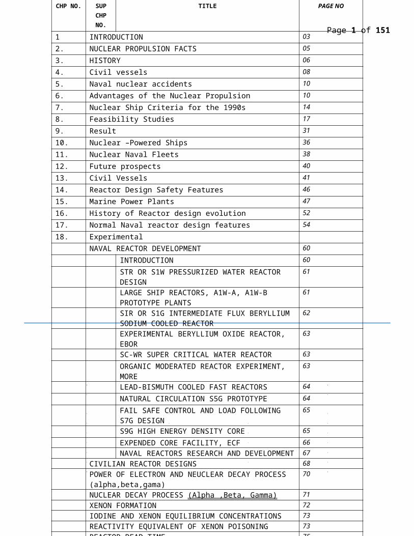
CHP NO. SUP CHP NO.
TITLE PAGE NO
1 INTRODUCTION 03
2. NUCLEAR PROPULSION FACTS 05
3. HISTORY 06
4. Civil vessels 08
5. Naval nuclear accidents 10
6. Advantages of the Nuclear Propulsion 10
7. Nuclear Ship Criteria for the 1990s 14
8. Feasibility Studies 17
9. Result 31
10. Nuclear –Powered Ships 36
11. Nuclear Naval Fleets 38
12. Future prospects 40
13. Civil Vessels 41
14. Reactor Design Safety Features 46
15. Marine Power Plants 47
16. History of Reactor design evolution 52
17. Normal Naval reactor design features 54
18. Experimental NAVAL REACTOR DEVELOPMENT 60
INTRODUCTION 60
STR OR S1W PRESSURIZED WATER REACTOR DESIGN 61
LARGE SHIP REACTORS, A1W-A, A1W-B PROTOTYPE PLANTS
61
SIR OR S1G INTERMEDIATE FLUX BERYLLIUM SODIUM COOLED REACTOR
62
EXPERIMENTAL BERYLLIUM OXIDE REACTOR, EBOR 63
SC-WR SUPER CRITICAL WATER REACTOR 63
ORGANIC MODERATED REACTOR EXPERIMENT, MORE 63
LEAD-BISMUTH COOLED FAST REACTORS 64
NATURAL CIRCULATION S5G PROTOTYPE 64
FAIL SAFE CONTROL AND LOAD FOLLOWING S7G DESIGN 65
S9G HIGH ENERGY DENSITY CORE 65
EXPENDED CORE FACILITY, ECF 66NAVAL REACTORS RESEARCH AND DEVELOPMENT 67
CIVILIAN REACTOR DESIGNS 68POWER OF ELECTRON AND NEUCLEAR DECAY PROCESS (alpha,beta,gama)
70
NUCLEAR DECAY PROCESS (Alpha ,Beta, Gamma) 71XENON FORMATION 72IODINE AND XENON EQUILIBRIUM CONCENTRATIONS 73REACTIVITY EQUIVALENT OF XENON POISONING 73REACTOR DEAD TIME 75ESTIMATION OF NECLEAR WASTE GENRATION BY REACTOR 76Nuclear waste Management 80Reprocessing 81Immobilising high-level waste 82Layers of protection 84Approaches to radioactive waste disposal 84Options being aired for disposing radioactivityNuclear power inevitable option 90Long Term Nuclear Power program 90
Page 2 of 107
Marine Nuclear Propulsion{ Given the current concern about global warming and the rising cost of fossil fuels, should the shipping industry be seriously considering nuclear-powered commercial ships? The world's first nuclear-powered merchant ship, the N.S. Savannah, is now moored in Norfolk, Va., ready to undergo a multimillion dollar dry-docking at the Norfolk Ship Repair Unit of BAE Systems. Now a National Historic Landmark vessel, the Savannah had its nuclear fuel removed more than 30 years ago. A recent study conducted under the sponsorship of the Center for Commercial Deployment of Transportation Technologies (CCDOTT) examined the feasibility of a fleet of nuclear-powered 9,200-TEU containerships in a U.S. West Coast-Far East trade. The study, "Analysis of High-Speed Trans-Pacific Nuclear Containership Service," conducted by George A. Sawyer and Joseph A. Stroud, General Management Partners, LLC, examined whether such nuclear-powered ships would be both technically feasible and economically competitive in such service. The study assumes that the timeline for the initial service would be 10 to 12 years in the future. What's attractive from a green standpoint, of course, is that the nuclear-powered ship is the zero air emissions ship, but just the mention of nuclear power gets environmentalists fuming. Sawyer, the former Assistant Secretary of the U.S. Navy and a founding member of J.F. Lehman & Co., and Stan Wheatley, Manager, CCDOTT, recently spoke about the nuclear-powered box-ship concept as part of a panel discussion at Marine Log's Global Greenship in Washington, D.C. In the study, the conceptual design for the 9,200-TEU nuclear-powered containership was based on the lines of the diesel-powered OOCL Shenzhen. The nuclear-powered concept vessel ended up being lengthened by 42 meters to 365m (1,198 ft) overall in order to better accommodate the increased powering required. The lengthening resulted in a 4 knot improvement in the speed at the design horsepower and, because of the total weight saved by omitting about 8,900 tons net of fuel, permitted the load-out of additional 1000 + 40 foot containers. The ship would be powered by an integrated nuclear and conventional propulsion and powering system consisting of a single Pressurized Water Reactor (PWR) utilizing Rolls-Royce provided commercial technology suitably modified for the ship motions, accelerations and transients expected of a high speed maneuvering marine application. The propulsion-powering system used in the study assumes an all-electric system consisting of an integrated mix of primary nuclear, auxiliary diesel, and emergency diesel or battery-powered generators all interconnected on a dual 4,160 volt bus. The propulsion motor concept used in the study is the permanent magnet motor currently under development and full-scale demonstration by the U.S. Navy. In an emergency situation, the flexibility of the propulsion system would allow the auxiliary diesels to drive the ship at 15 knots with the nuclear plant shut down. Propulsion power will be 273,000 shp. The study envisioned a hypothetical nuclear-powered, 35-knot, three-ship express service making weekly calls between the Ports of Hong Kong and Long Beach/Los Angeles. This hypothetical service was compared with a four-ship 25-knot conventional service employing the same sized vessels using diesel technology. The results of the comparison showed that under certain assumptions, the conceptual nuclear containership service would be economically viable with a crossover point compared to the diesel service at basic oil costs of about $89 per barrel. Last month, the price of a barrel of oil eclipsed $92. The hypothetical weekly three-ship, high-speed nuclear ship express service (10 days on-dock to on-dock transit time) equates to a four-ship conventionally powered fleet of equivalent size and capacity transiting at 25 knots to the same ports (13.5 days on-dock to on-dock transit days). This high utilization rate, says the study, would require refueling the nuclear reactors at about five-year intervals, with the refueling outage for each vessel consisting of 35 days at a nuclear capable shipyard employing the ship's on-board refueling system. The study included a considerable economic penalty in its analyses to account for both maintaining the continuity of service and the significant direct costs involved in these refueling outages. At current conventional marine fuel prices and assuming that large ships will be required to burn low sulphur marine diesel within 40 miles of shore, the Net Present Value at 10% of the conventional fleet is $259 million while the NPV of the base case nuclear fleet is $10 million. This gap, says the study, is not too large to overcome, and after analyzing some of the largest variables, it projects that a long distance high-speed commercial nuclear service could well become viable in the foreseeable future--10 to 15 years.
Page 3 of 107
Still, the initial investment to build the nuclear-powered ship would make many an owner weak-kneed. A single ship would cost $722 million, plus an initial $113 million for the reactor core. By comparison, the study puts the cost of the diesel-powered ship in the neighborhood of $150 million. }
Introduction:-
The shipping industry has just celebrated a notable golden anniversary, the Soviet icebreaker Lenin having entered service on 3 December 1959 as the world’s first nuclear-powered surface ship. Although the use of nuclear reactors to propel ships in the years since that historic day has been primarily limited to naval vessels, interest in the potential for nuclear power to drive merchant ships is currently resurgent. The high price of oil and growing pressures to reduce ship atmospheric emissions are supporting a reappraisal of the role nuclear power might play in the future.
Experience with nuclear-powered cargo ships over the past half century is extremely limited and hardly amounts to a ringing endorsement of this option as a viable propulsion system for merchant vessels. Only four such ships were ever built - Savannah, Otto Hahn, Mutsu and Sevmorput. The first three proved not to be commercially viable. Only the Russian, 1988-built, 61,900 DWT Sevmorput has enjoyed a useful working life; the icebreaking lighter aboard ship/container vessel has been serving northern Russian ports for over two decades.
The 22,000 DWT, US-built Savannah was commissioned in 1962 and, although it proved to be a technical success, it was decommissioned eight years later. The German-built, 15,000 DWT cargo ship/research vessel Otto Hahn achieved a similar service record; it sailed some 650,000 nautical miles on 126 voyages in 10 years without any technical problems. However, the vessel proved to be too expensive to operate on nuclear fuel and in 1982 it was converted to diesel.
The 8,000 DWT, 1970-built Japanese cargo ship Mutsu was dogged by technical problems from the outset and political sensitivities prompted its early removal from service. Sevmorput, too, was beleaguered by technical problems until its first set of reactors was replaced.
However, today’s advocates of nuclear propulsion systems point out that the circumstances that pertained when these pioneering vessels made their appearances are totally different from present operating conditions. The US Maritime Administration realized from the outset, with oil at rock bottom prices in the early 1960s, that Savannah was never going to be a commercial proposition. Rather, the ship was built purely to demonstrate the technical feasibility of nuclear propulsion, something that was proven by Savannah’s cumulative safety and reliability performance.
It was said that, if required, the fine-lined ship could have circled the globe 14 times at 20 knots without refueling. Another factor that compromised Savannah’s commercial viability was the rapid rise of containerization from the mid-1960s onwards; the ship’s narrow holds were unsuitable for loading either boxes or other than a small volume of cargo. At today’s prices, Savannah cost USD 350 million to build, 60% of which was accounted for by the nuclear power plant alone.
As oil prices have skyrocketed in the decades since Savannah put to sea, the cost of building a marine nuclear propulsion system has dropped dramatically, not least because of the advances in technology and the ability to construct relatively small “appliance grade” reactors customized for the requirements of a particular ship. Reactor designers are also at pains to highlight the advances that have been made in controlling and minimizing risk and enhancing safety and reliability.
Page 4 of 107
In the past two years several classification societies have launched technical investigations into the potential for applying nuclear power to a new generation of merchant ships. The early focus of this work has been on propulsion units for tankers, bulk carriers, container ships and cruise ships, but it is acknowledged that other ship types are also potential beneficiaries of the nuclear option. The reviews have encompassed aspects such as refuelling, waste disposal options, public health matters, manning, training, operational risk and regulatory requirements.
Nuclear power is an emotive subject and accidents like Three Mile Island in 1979 and Chernobyl in 1986 have saddled the nuclear industry with a considerable amount of baggage. While the advocates point out that modern reactor design is such that these well-known disasters could not be repeated, much needs to be done to alter negative public perceptions and to convince the shipping industry of the acceptability of nuclear plants on their ships.
The US and Russian navies each have fleets of over 100 nuclear-powered surface ships and submarines. Furthermore, each of these fleets has accumulated over 6,000 accident-free “reactor years”. There are another 50 or so nuclear warships operating amongst the French, UK, Chinese and Indian navies. In addition to these naval vessels, Russia has five oceangoing and two river class nuclear icebreakers in operation. Backing up the naval experience are approximately 440 nuclear power plants in commercial operation in 31 countries worldwide. These facilities, between them, generate 15% of the world’s electricity.
The reactors onboard most of the global fleet of 250 or so active nuclear ships are of the pressurised water reactor (PWR) type and this technology has demonstrated a notable safety and reliability record. In addition, other nuclear technologies may soon be available for use as ship propulsion systems, including a range of high-temperature reactors, the pebble-bed concept and design options based on the original PWR power units.
Because a nuclear reactor has no carbon footprint, the climate change benefits of nuclear propulsion for ships are immediately apparent. In addition, the need to comply with sulphur emission control area (SECA) requirements would not be a factor, nor would the risk of a bunker spill. Furthermore, the types of reactor now being proposed for marine applications would have a service life of 40 years and would be able to operate for five or six years before the need for refuelling with enriched uranium. A 30-day period for refuelling operations is envisaged.
The provision of reactors able to meet modern marine power and other service requirements is not envisaged as being a problem. For example, reasonably sized power plants capable of delivering 200,000 horsepower - enough to propel the new generation of very large container ships now entering service at the 25-knot service speeds common in the deepsea container ship sector until recently - have already proven themselves in aircraft carrier service. Such units could also be used in a reverse cold ironing role to provide power to the port community while the ship is berthed.
Guessing what the price of oil will be 40 years hence requires a leap into the unknown. However, cost comparisons based on today’s oil prices reveal very low nuclear fuel costs compared to current bunkering costs. It is acknowledged that the capital cost of a reactor as well as the other costs associated with its life cycle operation, including its final disposal, would be much higher than the comparable costs associated with a conventional ship power plant. However, these disadvantages would be easily outweighed by the savings in fuel costs that a nuclear plant could achieve after only a few years in operation.
The business models for the purchase and operation of a nuclear-powered ship would be significantly different from those that have been traditionally employed for conventional vessels. A key difference is that, because the fuel cost is included in the cost of the reactor, the majority of the costs would be incurred early in the ship’s life cycle, during the construction and commissioning stages.
Page 5 of 107
Of course, for the shipping industry to make the great leap to nuclear power for its merchant ships, any embrace of new business models would have to be accompanied by a major cultural shift. To achieve the life cycle and environmental benefits offered by nuclear propulsion, the maritime community will have to reassess earlier perceptions and ensure that the real risks are managed to everyone’s satisfaction.
Nuclear propulsion facts
Naval reactors are pressurized water, liquid-metal-cooled, or boiling water types, which differ from commercial reactors producing electricity in that:
they have a high power density in a small volume; some run on low-enriched uranium (requiring frequent refuelings), others run on highly enriched uranium (>20% U-235, varying from over 96% in U.S. submarines (no refuelings are necessary during the submarine's service life) to between 30–40% in Russian submarines to lower levels in some others),
the fuel is not UO2 (Uranium Oxide) but a metal-zirconium alloy (circa 15% U with 93% enrichment, or more U with lower enrichment),
the design enables a compact pressure vessel while maintaining safety.
The long core life is enabled by the relatively high enrichment of the uranium and by incorporating a "burnable poison" in the cores which is progressively depleted as fission products and Minor actinides accumulate, leading to reduced fuel efficiency. The two effects cancel one another out. One of the technical difficulties is the creation of a fuel which will tolerate the very large amount of radiation damage. It is known that during use the properties of nuclear fuel change; it is quite possible for fuel to crack and for fission gas bubbles to form.
Long-term integrity of the compact reactor pressure vessel is maintained by providing an internal neutron shield. (This is in contrast to early Soviet civil PWR designs where embrittlement occurs due to neutron bombardment of a very narrow pressure vessel.)
Reactor sizes range up to 190 MW in the larger submarines and surface ships. The French Rubis class submarines have a 48 MW reactor which needs no refueling for 30 years.
The Russian, U.S. and British navies rely on steam turbine propulsion, while the French and Chinese use the turbine to generate electricity for propulsion (turbo-electric propulsion). Most Russian submarines as well as all surface ships since USS Enterprise (CVN-65) are powered by two reactors. U.S., British, French and Chinese submarines are powered by one.
Decommissioning nuclear-powered submarines has become a major task for US and Russian navies. After defuelling, U.S. practice is to cut the reactor section from the vessel for disposal in shallow land burial as low-level waste (see the Ship-Submarine recycling program). In Russia, the whole vessels, or the sealed reactor sections, typically remain stored afloat, although a new facility near Sayda Bay is beginning to provide storage in a concrete-floored facility on land for some submarines in the Far North.
Russia is well advanced with plans to build a floating nuclear power plant for their far eastern territories. The design has two 35 MWe units based on the KLT-40 reactor used in icebreakers (with refueling every four years). Some Russian naval vessels have been used to supply electricity for domestic and industrial use in remote far eastern and Siberian towns.
Page 6 of 107
Harold Wilson, the then British Prime Minister, considered, but did not deploy, nuclear submarines to power Belfast during the Ulster Workers' Council Strike.
History
Work on nuclear marine propulsion started in the 1940s, and the first test reactor started up in USA in 1953. The first nuclear-powered submarine, USS Nautilus (SSN-571), put to sea in 1955. Much of the early development work on naval reactors was done at the Naval Reactor Facility on the campus of the Idaho National Laboratory.
Under the leadership of Hyman Rickover, the Navy contracted the Westinghouse Electric Corporation to construct, test and operate a prototype submarine reactor plant. This first reactor plant was called the Submarine Thermal Reactor, or STR. On March 30, 1953, the STR was brought to power for the first time and the age of naval nuclear propulsion was born. One of the greatest revolutions in the history of naval warfare had begun.
To test and operate his reactor plant, Rickover put together an organization which has thrived to this day. Westinghouse's Bettis Atomic Power Laboratory was assigned responsibility for operating the reactor it had designed and built. The crew was increasingly augmented by naval personnel as the cadre of trained operators grew. Admiral Rickover ensured safe operation of the reactor plant through the enforcement of the strictest standards of technical and procedural compliance.
At the site and at the STR, two missions for the prototype quickly emerged. First was the research and development of advanced reactor plant designs and procedures for the fleet. Second was the mission of training and certifying operators for the fleet. And the fleet came quickly and in large numbers. STR was redesigned S1W, the prototype of the USS NAUTILUS and was followed in the middle to late '50s by A1W, the prototype of the aircraft carrier, USS ENTERPRISE. Also in the late '50s, the Expended Core Facility was built. It is used to this day to examine expended naval reactor fuel to aid in the improvement of future generations of naval reactors. Finally, in the middle 1960s, S5G, the prototype of the submarine, USS NARWHAL, and predecessor to the reactor plant used to propel the Trident Fleet Ballistic Missile Submarines, was built and place in service.
As the Navy's presence expanded in eastern Idaho, slowly but surely the Navy support organization matured. By late 1954, the Nuclear Power Training Unit was established. In 1961, the Naval Administrative Unit set up shop in Blackfoot. In 1965, the unit moved to its present location in Idaho Falls, and over the next 30 years, continued to expand and improve its services. By 1979, a separate Personnel Support Detachment had arrived. 1982 saw a branch dental clinic established, and 1983 ushered in a branch medical clinic.
In the early 1950s work was initiated at the Idaho National Engineering and Environmental Laboratory to develop reactor prototypes for the US Navy. The Naval Reactors Facility, a part of the Bettis Atomic Power Laboratory, was established to support development of naval nuclear propulsion. The facility is operated by Westinghouse Electric Corporation under the direct supervision of the DOE's Office of Naval Reactors. The facility supports the Naval Nuclear Propulsion Program by carrying out assigned testing, examination, and spent fuel management activities.
The facility consists of three naval nuclear reactor prototype plants, the Expended Core Facility, and various support buildings. The submarine thermal reactor prototype was constructed in 1951 and shut down in 1989; the large ship reactor prototype was constructed in 1958 and shut down in 1994; and the submarine reactor plant prototype was constructed in 1965 and shut down in 1995. The prototypes were used to train sailors for the nuclear navy and for

Page 7 of 107
research and development purposes. The Expended Core Facility, which receives, inspects, and conducts research on naval nuclear fuel, was constructed in 1958 and is still operational.
The initial power run of the prototype reactor (S1W) for the first nuclear submarine, the Nautilus, was conducted at the INEEL in 1953. The A1W prototype facility consists of a dual-pressurized water reactor plant within a portion of the steel hull designed to replicate the aircraft carrier Enterprise. This facility began operations in 1958 and was the first designed to have two reactors providing power to the propeller shaft of one ship. The S5G reactor is a prototype pressurized water reactor that operates in either a forced or natural circulation flow mode. Coolant flow through the reactor is caused by thermal circulation rather than pumps. The S5G prototype plant was installed in an actual submarine hull section capable of simulating the rolling motions of a ship at sea. The unique contributions of these three reactor prototypes to the development of the United States Nuclear Navy make them potentially eligible for nomination to the National Register of Historic Places.
The Test Reactor Area (TRA) occupies 102 acres in the southwest portion of the INEL. The TRA was established in the early 1950s with the development of the Materials Test Reactor. Two other major reactors were subsequently built at the TRA: the Engineering Test Reactor and the Advanced Test Reactor. The Engineering Test Reactor has been inactive since January 1982. The Materials Test Reactor was shut down in 1970, and the building is now used for offices, storage, and experimental test areas. The major program at the TRA is now the Advanced Test Reactor. Since the Advanced Test Reactor achieved criticality in 1967, it's been used almost exclusively by the Department of Energy's Naval Reactors Program. After almost 30 years of operation, this reactor is still considered a premier test facility. And it's projected to remain a major facility for research, radiation testing, and isotope production into the next century.
The Navy makes shipments of naval spent fuel to INEL that are necessary to meet national security requirements to defuel or refuel nuclear powered submarines, surface warships, or naval prototype or training reactors, or to ensure examination of naval spent fuel from these sources. The Secretary of Defense, upon notice to the Governor of the State of Idaho, certifies the total number of such shipments of naval spent fuel required to be made through the year 2035. The Navy will not ship more than twenty four (24) shipments to INEL from the date of this Agreement through the end of 1995, no more than thirty six (36) shipments in 1996, and no more than twenty (20) shipments per year in calendar years 1997 through 2000. From calendar year 2001 through 2035, the Navy may ship a running average of no more than twenty (20) shipments per year to INEL. The total number of shipments of naval spent fuel to INEL through 2035 shall not exceed 575. Shipments of naval spent fuel to INEL through 2035 shall not exceed 55 metric tons of spent fuel.
This marked the transition of submarines from slow underwater vessels to warships capable of sustaining 20-25 knots (37-46 km/h) submerged for many weeks.
Nautilus led to the parallel development of further (Skate-class) submarines, powered by single reactors, and a cruiser, Long Beach, followed in 1961 and was powered by two reactors. The aircraft carrier, USS Enterprise (CVN-65), commissioned in 1962, was powered by eight reactor units in 1960. Enterprise remains in service.
By 1962 the United States Navy had 26 nuclear submarines operational and 30 under construction. Nuclear power had revolutionized the Navy. The technology was shared with the United Kingdom, while French, Soviet, Indian and Chinese developments proceeded separately.
After the Skate-class vessels, reactor development proceeded and in the USA a single series of standardized designs was built by both Westinghouse and General Electric, one reactor powering each vessel. Rolls Royce built similar units for Royal Navy submarines and then developed the design further to the PWR-2 (pressurized water reactor).
Page 8 of 107
The largest nuclear submarines ever built are the 26,500 tonne Russian Typhoon class.
Civil vessels
Development of nuclear merchant ships began in the 1950s, but has not generally been commercially successful. The US-built NS Savannah, was commissioned in 1962 and decommissioned eight years later. It was a technical success, but not economically viable. The German-built Otto Hahn cargo ship and research facility sailed some 650,000 nautical miles on 126 voyages in 10 years without any technical problems. However, it proved too expensive to operate and was converted to diesel. The Japanese Mutsu was the third civil vessel. It was dogged by technical and political problems and was an embarrassing failure. All three vessels used reactors with low-enriched uranium fuel.
The fourth nuclear merchant ship, Sevmorput, operates successfully in the specialised environment of the Northern Sea Route.
Nuclear propulsion has proven both technically and economically feasible for nuclear powered icebreakers in the Soviet Arctic. The power levels and energy required for icebreaking, coupled with refueling difficulties for other types of vessels, are significant factors. The Soviet icebreaker Lenin was the world's first nuclear-powered surface vessel and remained in service for 30 years, though new reactors were fitted in 1970. It led to a series of larger icebreakers, the 23,500 ton Arktika class, launched from 1975. These vessels have two reactors and are used in deep Arctic waters. NS Arktika was the first surface vessel to reach the North Pole.
For use in shallow waters such as estuaries and rivers, shallow-draft Taymyr class icebreakers with one reactor are being built in Finland and then fitted with their nuclear steam supply system in Russia. They are built to conform with international safety standards for nuclear vessels.
Nuclear propulsion has proven technically and economically essential in the Russian Arctic where operating conditions are beyond the capability of conventional icebreakers. The power levels required for breaking ice up to 3 metres thick, coupled with refuelling difficulties for other types of vessels, are significant factors. The nuclear fleet, with six nuclear icebreakers and a nuclear freighter, has increased Arctic navigation from 2 to 10 months per year, and in the Western Arctic, to year-round.
The icebreaker Lenin was the world's first nuclear-powered surface vessel (20,000 dwt), commissioned in 1959. It remained in service for 30 years to 1989, being retired due to the hull being worn thin from ice friction. It initially had three 90 MWt OK-150 reactors, but these were badly damaged during refueling in 1965 and 1967. In 1970 they were replaced by two 171 MWt OK-900 reactors providing steam for turbines which generated electricity to deliver 34 MW at the propellers.
It led to a series of larger icebreakers, the six 23,500 dwt Arktika-class, launched from 1975. These powerful vessels have two 171 MWt OK-900 reactors delivering 54 MW at the propellers and are used in deep Arctic waters. The Arktika was the first surface vessel to reach the North Pole, in 1977. Rossija, Sovetskiy Soyuz and Yamal were in service towards the end of 2008, with Sibir decommissioned and Arktika retired in October 2008.
The seventh and largest Arktika class icebreaker - 50 Years of Victory (50 Let Pobedy) - was built by the Baltic shipyard at St Petersburg and after delays during construction it entered service in 2007 (twelve years later than the 50-year anniversary of 1945 it was to commemorate). It is 25,800 dwt, 160 m long and 20m wide, and is designed to break through ice up to 2.8 metres thick. Its performance in service has been impressive.
Page 9 of 107
For use in shallow waters such as estuaries and rivers, two shallow-draft Taymyr-class icebreakers of 18,260 dwt with one reactor delivering 35 MW were built in Finland and then fitted with their nuclear steam supply system in Russia. They are built to conform with international safety standards for nuclear vessels and were launched from 1989.
Development of nuclear merchant ships began in the 1950s but on the whole has not been commercially successful. The 22,000 tonne US-built NS Savannah, was commissioned in 1962 and decommissioned eight years later. It was a technical success, but not economically viable. It had a 74 MWt reactor delivering 16.4 MW to the propeller. The German-built 15,000 tonne Otto Hahn cargo ship and research facility sailed some 650,000 nautical miles on 126 voyages in 10 years without any technical problems. It had a 36 MWt reactor delivering 8 MW to the propeller. However, it proved too expensive to operate and in 1982 it was converted to diesel.
The 8000 tonne Japanese Mutsu was the third civil vessel, put into service in 1970. It had a 36 MWt reactor delivering 8 MW to the propeller. It was dogged by technical and political problems and was an embarrassing failure. These three vessels used reactors with low-enriched uranium fuel (3.7 - 4.4% U-235).
In 1988 the NS Sevmorput was commissioned in Russia, mainly to serve northern Siberian ports. It is a 61,900 tonne 260 m long LASH-carrier (taking lighters to ports with shallow water) and container ship with ice-breaking bow. It is powered by the same KLT-40 reactor as used in larger icebreakers, delivering 32.5 propeller MW from the 135 MWt reactor, and it needed refuelling only once to 2003.
A more powerful Russian icebreaker of 110 MW net and 55,600 dwt is planned, with further dual-draught ones of 32,400 dwt and 60 MW power at propellers. The first of these third-generation icebreakers is expected to be finished in 2015 at a cost of RUB 17 billion.
Russian experience with nuclear powered Arctic ships totals about 300 reactor-years in 2009. In 2008 the Arctic fleet was transferred from the Murmansk Shipping Company under the Ministry of Transport to Atomflot, under Rosatom.
In August 2010 two Arktika-class icebreakers escorted the 100,000 dwt tanker Baltika, carrying 70,000 tonnes of gas condensate, from Murmansk to China via the Arctic route, saving some 8000 km compared with the Suez Canal route. There are plans to ship iron ore and base metals on the northern sea route also.
Naval nuclear accidents
Two US nuclear submarines, the USS Thresher (SSN-593) (sank) and USS Scorpion (SSN-589) (sank) had issues unrelated to their reactor plants and still lie on the Atlantic sea floor. The Russian or Soviet Komsomolets K-278 (sank), Kursk K-141 (sank), K-8 (sank), K-11 (refueling criticality), K-19 (loss of coolant), K-27 (scuttled), K-116 (reactor accident), K-122 (reactor accident), K-123 (loss of coolant), K-140 (power excursion), K-159 (radioactive discharge), K-192 (loss of coolant), K-219 (sank after collision), K-222 (uncontrolled startup), K-314 (refueling criticality), K-320 (uncontrolled startup), K-429 (radioactive discharge), and K-431 (reactor accident) submarines have all had problems of some kind. The Soviet icebreaker Lenin is also rumored to have had a nuclear accident.
While not all of those were nuclear-related accidents, since they happened to nuclear vessels, they have a major impact on nuclear marine propulsion and the global politics.
Page 10 of 107
Advantages of the nuclear propulsion
Atomic engines offer capabilities that cannot be achieved with fossil fuel engines. Nuclear fission requires no oxygen and produces no exhaust gases, and nuclear reactors are reliable, compact sources of continuous heat that can last for years without new fuel. These beyond competition capabilities have encouraged the development of certain types of nuclear systems without much regard for cost. Economic concerns are low on the priority list if the desired product is a high endurance submarine or a speedy aircraft carrier capable of independent operations. Of course, contractors love to work for a customer who has a "cost is no object" mentality.
Conventional wisdom states that the high cost of military nuclear ships proves that nuclear power cannot compete in less specialized markets. That is roughly equivalent to stating that the cost of military toilet seats and hammers proves that those items will be beyond the reach of the average American worker.
Advanced nuclear technologies and a careful focus on cost conscious design can result in nuclear propulsion systems that are economically superior to conventional systems for a wide variety of commercial applications. The nuclear gas turbine, for example, offers the simplicity and low capital investment of combustion gas turbines combined with the high endurance, low fuel cost and zero emission characteristic of nuclear powered systems. This concept should attract the attention of commercial shipping industry decision makers in their unending quest for a competitive advantage.
While Nuclear propulsion is quite prevalent in navy vessels of the various navies around the world, the same hasn’t been used to great success in the merchant vessel primarily due to massive public antipathy and considerable misconception, despite the absence of any reported accidents with nuclear reactors of the ships previously operated and obvious advantages of nuclear energy for s…. raising. As of Today no truly commercial nuclear powered ships are still in service, the celebrated ships Lenin, Savannah, Mutsu and Otto Hahn, have either been re-engined or withdrawn from service, but nuclear powered ice-breakers are still used by some countries like Russia.
Problems were experienced with some of the pioneer vessels level the most insurmountable obstacle was refusal of many port authorities to allow these nuclear powered vessels to enter ports, severely restricting their sphere of operation. On the contrary nuclear power is popular for naval vessels; since it doesn’t require air (ideal for submarines) and in a very potent source of energy. The most forthright advocate of nuclear power is US Navy which uses it to power almost all its submarines, large aircraft carriers and several cruisers.
Despite the political and other factors thwarting the significant use of nuclear power in ships, the some key disadvantages and some minor disadvantages. The major advantages are:-
Long periods between refuelling operations and considerable endurance range for vessel after each refuelling. [capabilities like dry-dock to dry-dock refuelling operation is easily possible].
Huge quantities of fuel need not be transported with resultant weight savings and space needed for fuel, Besides a reduction in manpower required for refuelling operation.
As nuclear power in not dependent on air for combustion, it is very useful choice for sub marine propulsion. For surface ship there is not exhaust to give the ship a neat Signature and no pollution to atmosphere by exhaust emissions.
There are no changes in ship draft and trim as the fuel is consumed.
Page 11 of 107
Nuclear plant is very simple to control, it responds Instantly to load demand changes and can supply quantities of high-pressure steam.
Technology such nuclear gas turbine can cause to increase the Dynamic advantages combining those of nuclear power plant and Gas turbine and getting steam out of the equation.
Despite the several afore mentioned advantages there as shell same challenges. Which have to be addressed to make nuclear plant. more attractive to merchant ships.
The high cost of purchase and operation is a major deterent to commercial operator who will be concerned with profitable operation and return on investment. Since the full life operation of nuclear vessel under commercial trading condition is nonexistent full life operation cost estimation against me present diesels engine installation count the confirmed out is expected to diesel engine installation cant be confirmed but is expected to be much lower.
The cost of building and maintaining a nuclear plant are very high because of very stringent quality control necessary to ensure reliability and extremely important, the safety of the plant and the ship or crew.
Reactor plants are many and require very dense shielding to contain radiation the power is to weight ratio of the nuclear plants is only of advantage in large vessel.
The training of crews competent enough to operate nuclear plants is both true consuming and expensive has shown that there is great difficulty in attracting suitable qualified scientist to serve aboard ship. Training for nuclear plant operation is best under take in a military environment.
A nuclear reactor installed a ship would in value some design problem as hall,pitch, shock which have learn already learn meet by many design,put due to string at requirement for shock and flexibility control the naval reactors are unnecessary by expensive there is need to develop a commercial reactor specifically for merchant ship propulsion.
Most these reactors are of pressurized water type design that is which the steam generated was initially of relatively low temperature requiring redesigning of turbines.
Due to the above peculiarities of this type of power source,those are few special type of ships,where is could compete with the conventional power sources. The ship with the following, characteristics would slow greatest economic advantage in convention with commercial source of propulsion.
(a) Long trade route,
(b) Quick turnaround in ports
(c) Large dead weight capacity.
(d) Minimum shaft power of 20,000.
(e) Both sides navigate fully-loaded.
(f) Regular home or base port.
(g) Cargo suitable for nuclear shielding.
Page 12 of 107
During present day with new technological advancements the requirement (e),(f)n be more relaxed. These characteristics suggested the choice of ship operating at a relatively ship speed and over a long trading route, such a tankers, are carrier or container carrier. Dry cargo freighter with also port town and limited. Cargo is particularly unsuitable from commercial point of views. The system is also suitable for vessel which could accommodate the heavy machinery and the same five require very high machinery output. Ice breaking ships are the best examples, the breakers to operate in for northern latitudes and possibly. Cargo gas on tankers to transport fuel. Reserves from arctic region for general shipping most likely application is very large and fast containers and huge submarine tankers.
On January 17, 1955, the Nautilus reported "Underway on nuclear power." Her success clearly demonstrated that nuclear reactors could be used as the heat source for marine engines. In the forty years since that first nuclear propelled voyage, five of the world's navies have combined for well over a hundred million miles of nuclear powered ocean travel using over 700 marine nuclear reactors. Nuclear power, however, has had essentially no impact on commercial shipping. Only a handful of non- military nuclear powered ships were ever completed; most of them were launched more than 30 years ago. The only ones still in operation are Russian icebreakers.
This situation was not what was predicted by 1950s vintage visionaries. At first, the idea of nuclear engines for civilian ships seemed like a natural extension of the success of the nuclear submarine. Large passenger liners like the United States and the Queen Mary were prodigious oil burners, consuming 50 tons per hour at high speed. Fast cargo ships, like those used to transport perishable items were not as large or powerful, but they could consume 10-20 tons per hour. Even with oil priced at $20.00 per ton, fuel represented a significant operating cost, but even more critical was the fact that the fuel storage space needed for long-range, high speed travel limited the operating range of the ship.
In September, 1955, J. J. McMullen produced a report for the Maritime Administration which found that the following characteristics were important in determining whether or not nuclear power should be considered for a given ship type.
1. Long trade route 2. Quick turnaround in port 3. Dense cargo in unlimited supply 4. Large deadweight capacity 5. Minimum shaft horsepower of 20,000 6. Fuel for the round trip taken on at same port as payload 7. Payload carried both ways 8. Regular home port at one end of voyage 9. Smoke elimination to be an advantage 10. Cargo suitable for secondary nuclear shielding
The N.S. Savannah experience
McMullen's carefully considered criteria were ignored in the process of designing the first nuclear powered merchant. Instead, the design criteria for N.S. Savannah came from a politician. In the words of President Eisenhower, "Visiting ports of the world, it will demonstrate to people everywhere this peacetime use of atomic energy, harnessed for the improvement of human living. In part, the ship will be an atomic exhibit, carrying to all people practical knowledge of the usefulness of this new science in medicine, agriculture, and power production." (April 25, 1955)
N.S. Savannah was a show boat. She had beautiful lines, more resembling a very large yacht than a bulk cargo ship. She carried thirty spacious passenger cabins, a swimming pool, a public lounge, and dining facilities for a hundred people.
Page 13 of 107
Her cargo handling equipment was designed and placed for beauty, not function and her holds had a maximum capacity of about 9,000 tons.
Her propulsion plant was built by Babcock and Wilcox, a boiler manufacturer that had never before constructed a nuclear power plant. One goal of the program that had little to do with economically producing a competitive merchantman was to qualify another nuclear reactor manufacturer so that the navy contractors did not completely dominate the civilian market.
As might be expected, Savannah was never self-supporting. She spent three years in the demonstration business, visiting 55 domestic and foreign ports. She hosted dignitaries and received many admiring visitors. Following the successful completion of the planned demonstration phase, she was chartered to First Atomic Ship Transport, Inc. a wholly owned subsidiary of the American Export Isbrandtsen Lines, Inc.
She operated as a subsidized general cargo ship from 1965 until 1971. During this phase of operation, she did not attempt to carry passengers because the cost of serving them would have been more than their fares. She also did not attempt to maximize revenue, often waiting in port for several days for delivery of a cargo that did not even fill her holds. Her operating subsidy averaged approximately $2.9 million per year or approximately $2 million more than a conventionally fueled ship of similar size. According to the Comptroller General of the United States, $1.9 million of Savannah's subsidy could be attributed to the costs of initial nuclear training, a nuclear shore staff and a nuclear servicing facility. As a one of a kind ship, Savannah had to support these specialized facilities by herself.
Savannah was laid up during the fall of 1971. During the early to mid 1970s, there were some studies funded by nuclear suppliers and the federal government that investigated the possibility of using nuclear power for specialized applications. Again McMullen's criteria were ignored when the high level criteria specified was a 2000 ton surface effect ship with 140,000 SHP. Understandably, there was little interest in building such a ship on the part of commercial ship owners. There has been essentially no discussion of nuclear power for merchant ships in the industry for at least twenty years.
Nuclear Ship Criteria for the 1990sThe shipping business has changed dramatically since 1955. Ships have grown, the container revolution has cut in port turn-around times for general cargo ships, and international trade in high value cargos like automobiles and construction equipment has steadily increased. Many ships in busy port cities are now required to install expensive equipment and/or restrict their operations to meet anti-pollution laws that limit discharges of oil, stack gases, and ballast water. In order to
decide if nuclear power is now right for a particular ship, the following additional factors should be considered:
• Speed requirements • Volume limits • Emissions limits • Oil handling limits • Ballast water limits • Deck space limits • Need for flexible operation • Local cost, availability, and quality of fuel
Page 14 of 107
The following types of ships may benefit from nuclear power. Operators of these ships would be well advised to learn more about what uranium fuel can do. As usual, a detailed economic analysis will be required to reach a correct
propulsion plant decision.
• Large container ships • Automobile carriers • Refrigerated cargo ships • Long distance passenger ships • Logistics support ships • Commercial submarines • Bulk cargo carriers
The Need For SpeedAn example calculation might help explain the characteristics of nuclear propulsion that allow it to claim a speed advantage over oil burning ships. If a ship needs 26,000 shaft horsepower to travel at 17 knots, it will burn about 1700 gallons (6.4 tons) of bunker fuel every hour. If the same ship wished to increase speed to 25 knots to make a delivery schedule, the fuel rate would increase to 8500 gallons (32 tons) per hour while the power needs would increase to 130,000 SHP. It is obvious why fast ships are not generally considered to be an economical way to transport bulk cargo.
Even if oil is cheap, the space required for storage for a long trade route becomes a major concern. A ship like the above carrying goods from New York to Cape Town, South Africa would need at least 2.3 million gallons of fuel (6900 tons) to make the trip at 25 knots versus 673,000 gallons (2019 tons) at 17 knots. Even though the trip takes five days longer, space and fuel costs favor the slower journey.
With nuclear ships, fuel expenditures are minor, both in terms of weight and cost. At current nuclear fuel prices an SHP hour produced by fissioning slightly enriched uranium fuel costs less than one sixth as much as an SHP hour produced by burning residual oil. The advantage is even more dramatic when compared to distillate fuels. There is virtually no change in weight on a nuclear powered ship because of fuel consumption.
There are obvious advantages to increased speed if fuel consumption is less constraining. More cargo can be moved with the same number of ships. Cargo will spend less time at sea and more time where it is needed. Shippers will pay higher rates for certain types of cargo since they will save on financial carrying costs. Since a faster ship requires the same crew size as a slow one, productivity can increase be improved without painful layoffs.
ReliabilityNuclear ships have demonstrated a high degree of reliability. They have operated for decades in some of the world's harshest climates including the Persian Gulf and the Arctic Ocean. They are not subject to clogged fuel filters, burst fuel lines, loss of compressed starting air, contaminated fuel from substandard suppliers, bent rods, failed gaskets, or a whole host of other problems common to combustion engines. Even single reactor plant submarines comfortably operate under the Arctic ice cap where a loss of propulsion power can be deadly. The engines rarely fail. Since a substantial portion of the marine accidents can be blamed on propulsion casualties, this characteristic is an important advantage for nuclear power.
Power Density ComparisonsConventional wisdom holds that the weight of shielding needed for nuclear powered ships is more than the weight saved by the lowered fuel consumption. Savannah's propulsion plant weighed about 2500 tons including the shielding. Her specific power ratio was 238 lbs/hp (151 kg/kw), which is obviously not very competitive with today's medium speed
Page 15 of 107
diesels or gas turbines. However, Savannah's propulsion plant weight included enough fuel for 340,000 miles of operation. In contrast, a diesel engine system with a specific weight of 36 lbs/SHP (23 kg/kw) and a specific fuel consumption of .3 lbs/hp-hr (.2 kg/kw-hr) would match Savannah's characteristics if its required voyage lasted 28 days (13,000 miles at 20 knots), ignoring the weight of tanks, and piping and reserve fuel requirements.
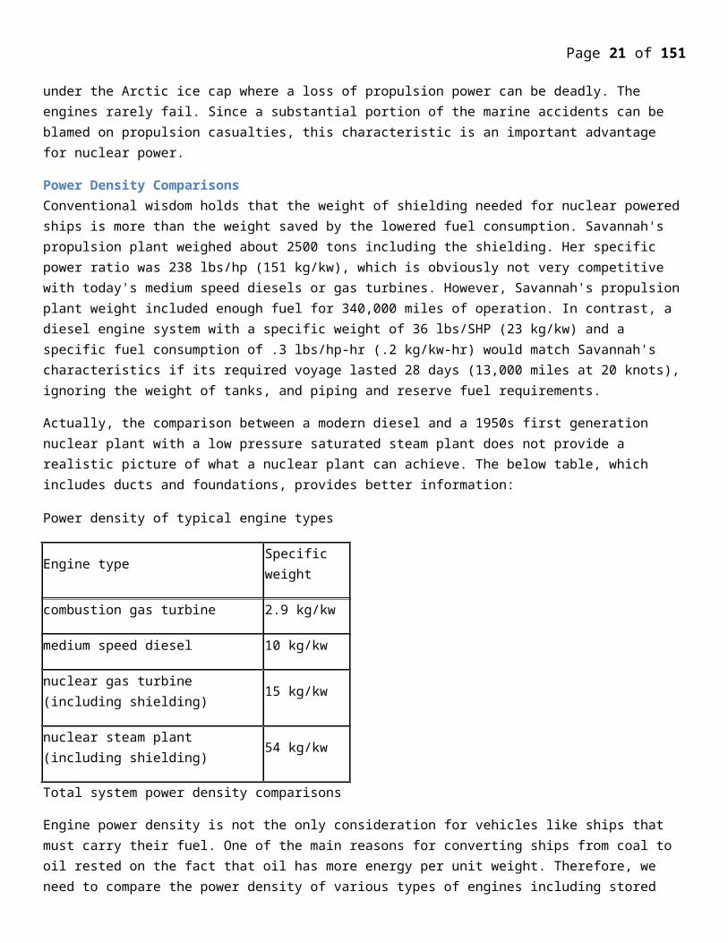
Actually, the comparison between a modern diesel and a 1950s first generation nuclear plant with a low pressure saturated steam plant does not provide a realistic picture of what a nuclear plant can achieve. The below table, which includes ducts and foundations, provides better information:
Power density of typical engine types
Engine type Specific weight
combustion gas turbine 2.9 kg/kw
medium speed diesel 10 kg/kw
nuclear gas turbine (including shielding) 15 kg/kw
nuclear steam plant (including shielding) 54 kg/kw
Total system power density comparisons
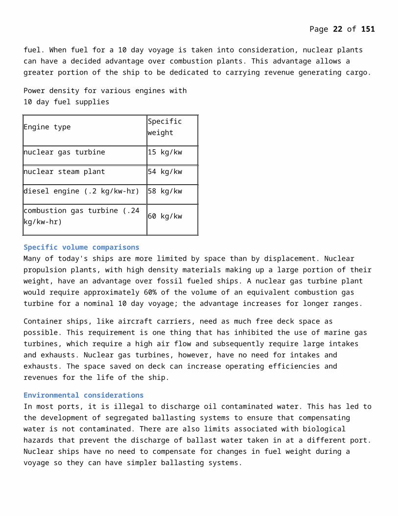
Engine power density is not the only consideration for vehicles like ships that must carry their fuel. One of the main reasons for converting ships from coal to oil rested on the fact that oil has more energy per unit weight. Therefore, we need to compare the power density of various types of engines including stored fuel. When fuel for a 10 day voyage is taken into consideration, nuclear plants can have a decided advantage over combustion plants. This advantage allows a greater portion of the ship to be dedicated to carrying revenue generating cargo.
Power density for various engines with 10 day fuel supplies
Engine type Specific weight
nuclear gas turbine 15 kg/kw
nuclear steam plant 54 kg/kw
diesel engine (.2 kg/kw-hr) 58 kg/kw
combustion gas turbine (.24 kg/kw-hr) 60 kg/kw
Specific volume comparisonsMany of today's ships are more limited by space than by displacement. Nuclear propulsion plants, with high density materials making up a large portion of their weight, have an advantage over fossil fueled ships. A nuclear gas turbine plant would require approximately 60% of the volume of an equivalent combustion gas turbine for a nominal 10 day voyage; the advantage increases for longer ranges.
Page 16 of 107
Container ships, like aircraft carriers, need as much free deck space as possible. This requirement is one thing that has inhibited the use of marine gas turbines, which require a high air flow and subsequently require large intakes and exhausts. Nuclear gas turbines, however, have no need for intakes and exhausts. The space saved on deck can increase operating efficiencies and revenues for the life of the ship.
Environmental considerationsIn most ports, it is illegal to discharge oil contaminated water. This has led to the development of segregated ballasting systems to ensure that compensating water is not contaminated. There are also limits associated with biological hazards that prevent the discharge of ballast water taken in at a different port. Nuclear ships have no need to compensate for changes in fuel weight during a voyage so they can have simpler ballasting systems.
Governments have implemented air emission limits in certain busy ports that require costly modifications to existing propulsion systems. Simple, but somewhat costly, solutions include separate bunkers with low sulfur (but more expensive) oil, and ship speed (power) limits when within certain boundaries. There is increasing pressure for the installation precipitators, selective catalytic reformers and scrubbers. Aside from the expense, these technologies can be difficult to adapt to ships because of space limitations. Nuclear ships do not emit any exhaust gases, a fact that is clearly demonstrated by the success of nuclear powered submarines.
Finally, rules on liability for oil spills are increasing the cost of bunkering. Provisions must be made for containment booms and stand-by response teams. Separate fueling piers are becoming common, requiring extra time in port and extra expense for tugs and pilots. Bottom tanks now need double hull protection, increasing the cost of both construction and operations. Nuclear ships will be refueled during scheduled maintenance periods; it is easily possible to
design cores that can last for six to ten years of normal ship operation.
Feasibility Studies:The UK ministry of technology set up a working party to study the probable cost and benefits to be derived from Nuclear. Propulsion – Nuclear power should give advantage of cheap fuel for mark purposes in terms of cost per effective horsepower, cheap in terms of saving in overall weight carried and cheap in terms of freedom from restrictions on the itinerary or taking on conventional bunker. Such economic and technical advantages cannot out weight the bigger capital cost of nuclear power unless large powers are required and just as important the type of source extended for ship also required that the capital investment of the slip as a means of transport will be exploited at a high rate of utilization with the minimum time spent tied up in post.
There is also a study group under the auspices of ministry of technology looking into the feasibility of 500000 to 1000000 tones tanker. Such has been the growth of oil tanker in past ten years. In 1967, the committee completed is first study of the application of nuclear powered container ships. The report presented the first stage result of an assessment of the potential advantages of nuclear power when applied to advanced container ship designs similar to those being developed at that time by a number of world shipping interest of huge speed container uses/ services. The conclusion of this report were best on the belief that the trend towards ship of higher power litigation would show and increasing advantage to nuclear propulsion using the designs of reactors currently being developed. A subsequent study verified this belief.
In 1968 a techno-economic study was made on the refrigerated container vessel for New Zealand trading. This vessel was subject of two papers. The result of this study was most encouraging and indicated that nuclear propelled vessels could show an economic advantage our conventional vessels operating on contain rates.
Page 17 of 107
The large container vessels set the trend for third generation of purpose – built containership and represent the sizes of vessel to which application of nuclear power is likely to show some economic advantage our the commercial form in future.
The results gained from the economic comparisons made were found to be most encouraging and further reinforced the long field belief that the application nuclear power to certain types of vessel over specific route would be commercially viable.
The commercial shipping industry has been around since the early 1900’s when the first vessel built purely for tourism was completed. From that single ship, the industry has grown to a $27 billion dollar industry carrying over 18 million passengers to destinations all around the world.
Modern cruise ships are as large as or larger than the largest aircraft carriers in service. Is the technology needed for nuclear power at sea and the fuel needed really that cost prohibitive? Or is the public stigma against nuclear power strong enough that it would make the ship unprofitable from a passenger count perspective?
Lloyd’s Register, the international standards organization for the classification and design of ships, announced in November 2010 that it has begun a two-year project with a consortium of companies to look into the feasibility of nuclear-powered commercial ships. The primary application will be for cargo ships, but all large vessels, including cruise ships, could use the technology if Lloyd’s Register endorses it.
It is true as it was reported that the nuclear potential was never transpired in a true sense due to the traditional anti concerns associated with safety, radiation exposure, and the size of the reactors but nuclear propulsion is already widespread in the world’ oceans in nuclear submarines, aircraft carriers, and Russian nuclear icebreakers. The military grade naval vessels are good examples to see the impact nuclear power has on large ships. Nuclear marine propulsion has been around since the 1950’s, and by 1960, 26 nuclear submarines were operation with another 30 under construction. United States aircraft carriers use nuclear power to desalinate the necessary water on their ships. For large carriers this represents 400,000 gallons per day. The US military use of nuclear reactors for naval propulsion is a testimony to enormous benefit of nuclear power.
The benefits of nuclear ship propulsion are so robust and vigorous that this technology can neither be ignored nor disregarded. Furthermore, considering climate change priorities which are becoming urgent concern at a global level, companies and governments around the world are now dusting off some of those old dreams for carbon-free nuclear-and shipping, which accounts for roughly 5 percent of global greenhouse gas emissions, seemed to Lloyd’s Register like a logical place to start.
A new generation of small reactors appear to be addressing some of those concerns. Hyperion Power Generation, a spin-off from Los Alamos National Laboratory in the U.S. and a member of the Lloyd’s Register consortium, has developed a “Small Modular Reactor” that produces 25 MW of electricity (Traditional power plant reactors produce up to 1,500 MW) using low enriched uranium. The company has big plans for its little reactors, which called “Nuclear Batteries.” They hope their little atom splitters can be used to power everything from American subdivisions to plants in the developing world. The design of these reactors attracted Lloyd’s Register.
The other consortium members are ship designers BMT Nigel Gee and Greek shipping company Enterprises Shipping and Trading. In addition to the technical challenges associated with this technology, one of the primary obstacles will be how the ships can be used in countries that are currently unfriendly or have statutory
Page 18 of 107
prohibitions of nuclear power. BMT Nigel Gee will be looking at the feasibility of a physical separation of the ship, meaning that the portion of the ship with the nuclear propulsion would be used for deep-sea transit but then remain in international waters while a large module with the cargo (or passengers) enters port under battery power.
Unfortunately, these Small Modular Reactors do not have universal support simply because some environmentalists argue the size of these reactors make them vulnerable to terrorist sabotage or theft. Consequently, it is not clear how investors will view a fleet of this kind of nuclear ships. Nuclear power requires political support, and another accident could at anytime swing sentiment against the nuclear technology. But Nick Brown, Maritime Communications Manager at Lloyd’s Register, says that, like nations themselves, the shipping industry has been forced by climate change to look at all alternatives to fossil fuels. He suggested that “There is this perception that nuclear represents an increased risk but really it needs to be one of the options we consider in how to manage the much larger risk of global climate change.”
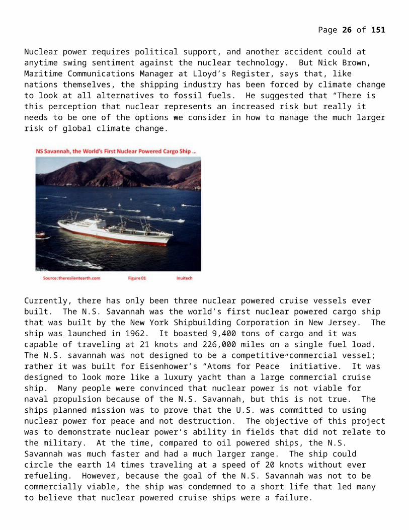
Currently, there has only been three nuclear powered cruise vessels ever built. The N.S. Savannah was the world’s first nuclear powered cargo ship that was built by the New York Shipbuilding Corporation in New Jersey. The ship was launched in 1962. It boasted 9,400 tons of cargo and it was capable of traveling at 21 knots and 226,000 miles on a single fuel load. The N.S. savannah was not designed to be a competitive commercial vessel; rather it was built for Eisenhower’s “Atoms for Peace” initiative. It was designed to look more like a luxury yacht than a large commercial cruise ship. Many people were convinced that nuclear power is not viable for naval propulsion because of the N.S. Savannah, but this is not true. The ships planned mission was to prove that the U.S. was committed to using nuclear power for peace and not destruction. The objective of this project was to demonstrate nuclear power’s ability in fields that did not relate to the military. At the time, compared to oil powered ships, the N.S. Savannah was much faster and had a much larger range. The ship could circle the earth 14 times traveling at a speed of 20 knots without ever refueling. However, because the goal of the N.S. Savannah was not to be commercially viable, the ship was condemned to a short life that led many to believe that nuclear powered cruise ships were a failure.
As the size of modern cruise ships continues to increase, the requirement for fuel, power, water and crew boosts costs at an exponential rate. While the technical details of cruise ships vary slightly, the largest ships have very similar power, fuel, water and crew requirements. These ships are over 1000 feet long with a height of over 230 feet above the water line and a depth of about 70 feet. They measure over 200,000 gross tons and displace about 100,000 tons. Almost all of the large commercial cruise ships are powered by 16-cylinder diesel engines that
Page 19 of 107
each output 25,000 hp (18,642 kW). The number of engines per ship varies but the largest cruise ship have six, with each consuming over 1,300 gallons of fuel per hour when in operation. This huge fuel requirement amounts to 187,200 gallons of fuel per day of operation.Each ship is built to hold over 5,000 passengers, which means that a massive amount of fresh water is needed for operation. The largest of cruise ships use over 260,000 gallons of fresh water every day. In order to meet this fresh water demand, a desalination process is used to convert the salt water into pure water. There are several different ways to desalinate water including reverse osmosis, ion exchange and multi-stage flash distillation. Currently, the two most popular methods are reverse osmosis and multi-stage flash distillation, and for our cruise ship design, we will be using multi-stage flash distillation. In multi-stage flash (MSF) distillation seawater vaporization takes place in a vacuum at low temperature. The reason vaporization takes place in a vacuum is that the boiling point of water is lower which means less energy is required to complete the vaporization. Before going into the heater, the cold sea water passes through condensing coils in the vacuum flash chambers which serve two purposes. They preheat the cold seawater before entering the heater and condense the already flashed steam in the chambers to produce the fresh water. Then the seawater enters a brine heater which heats the seawater to a temperature between 90 °C and 110 °C to boil the water. This process is done in multiple chambers to increase the quantity of the water product. The desalination process takes a huge amount of energy to complete. Energy is needed in two stages, electrical energy to pump the water and steam energy to heat the brine. In order to produce the 260,000 gallons of fresh water needed per day, a vast amount of power is needed to complete the necessary desalination. One of the major design hurdles is to find the most efficient way to accomplish this desalination while using the minimum amount of energy. In our design, we propose to couple our nuclear power cycle with a desalination plant. We will further discuss this aspect in the analysis section of the report.Despite the current economic situation, construction of cruise ships is still going strong. Royal Caribbean just introduced a new Genesis Class of cruise ships that will cost over $1 billion to build; it is the first non military vessel to be built with a price tag of over a billion dollars. The industry is only getting bigger, and with increased size, the desire for reduction in fuel and weight, as well as an improvement in speed distance and emissions will lead to the need for better technology.The pure volume of fuel being consumed by these massive vessels results in huge costs for the cruise liner. Current prices of bunker fuel for the cruise ships are around $650 per ton of fuel. If we assume the density of the marine fuel is around 970 kg/m3, this means that if a vessel consumes 187,200 gallons of fuel per day, the cost of just the fuel is $447,742 a day. This fact alone is enough to make the average person second guess the type of fuel used for commercial naval propulsion. Another problem is the amount of energy that is needed to desalinate enough ocean water to get 260,000 gallons of fresh water per day. Another major issue affecting desalination plants is corrosion of pipes because of the seawater. The Waterfields desalination plant in the Bahamas provides 2.64 million gallons of fresh water per day, but after 6 months of operation, the 316L stainless steel pipes began to show corrosion. The replacement was a AL-6XN alloy pipe, which has not corroded for over 10 years. We plan to use this material for all of our pipes such that no corrosion will take place.The most common propulsion system for current large cruise liners is a diesel-electric system. There are usually six main diesel engines that are attached to generators. Unlike older cruise ships the diesel engines are not directly attached to the propeller shafts, instead they are attached to generators so the entire system is electric. The ships also have 4 bow thrusters, each of the bow thrusters generate about 7,500 hp (5,592 kW) which leads to a total of roughly 30,000 hp (22,370 kW) when combined.
Currently, there has only been three nuclear powered cruise vessels ever built. The N.S. Savannah was the world’s first nuclear powered cargo ship and was built by the New York Shipbuilding Corporation in New Jersey. It was launched in 1962 and boasted 9,400 tons of cargo capable of traveling at 21 knots and 226,000 miles on a single fuel load. The N.S. savannah was widely considered a failure for many reasons; it was not designed to be a competitive commercial vessel, rather it was built for Eisenhower’s “Atoms for Peace” initiative. It was designed to look more like a luxury yacht than a large commercial cruise ship. Many people
Page 20 of 107
have resigned to the fact that nuclear power is not viable for naval propulsion because of the N.S. Savannah, however this is not true. The ships planned mission was to prove that the U.S. was committed to using nuclear power for peace and not destruction. It was to demonstrate nuclear power’s ability in fields that did not relate to the military. At the time, compared to oil powered ships, the N.S. Savannah was much faster and had a much larger range. The ship could circle the earth 14 times traveling at a speed of 20 knots without ever refueling. However, because the goal of the N.S. Savannah was not to be commercially viable, the ship was condemned to a short life which led many to believe that nuclear powered cruise ships were a failure.
One only has to look at military grade naval vessels to see the impact nuclear power has on large ships. Nuclear marine propulsion has been around since the 1950’s, and by 1960, 26 nuclear submarines were operation with another 30 under construction. United States aircraft carriers use nuclear power to desalinate the necessary water on their ships. For large carriers this is on the order of 400,000 gallons per day. The enormous benefit of nuclear power is the reason we see the U.S. military use nuclear reactors for naval propulsion.
In order to conduct a feasibility analysis of a nuclear powered cruise ship with desalination, we will propose two potential Rankine power cycles. Using Rankine cycles, we can thermodynamically model both power generation as well as desalination using the laws of conservation of mass and energy. Energy is the combination of the internal energy (U) of a system with all other energetic contributions including kinetic energy (KE) due to inertial velocity effects and potential energy (PE) due to body force effects which include gravity effects. Entropy is a thermodynamic quantity that represents the amount of energy in a system that can no longer accomplish mechanical work. It also measures the disorder or randomness of a closed system. Enthalpy is a thermodynamic quantity equal to the internal energy of a system plus the product of its volume and pressure. More generally, it is the amount of energy in a system capable of doing mechanical work.Methods
To see if a nuclear-desalination cycle can satisfy the necessary power and water requirements for a cruise ship, we obtain the specifications for both a commercial nuclear reactor as well as for a cruise ship. We apply these specifications to thermodynamic cycles to determine if the power and water needs can be met in an optimal way. Finally we solve for the desalination pressure that gives the desired fresh water flow rate.We obtained the specifications for a 500 MW electric nuclear power plant. The thermal power output is 1882 MW. Since no new nuclear power plants have been built in the United States since the early 1970s, we assume that efficiency has only improved in nearly 40 years. The specifications for the PWR we chose include four separate loops with four distinct steam generators, and a combined mass flow rate of 1.91 x 10⁶ kg/h, or 530 kg/s. For the sake of simplicity we convert the four loops to one, and assume that the mass flow rate scales in proportion to the number of loops. Thus the working fluid mass flow rate we use is . The basic PWR power plant with only one loop is shown in Figure 1. Since PWR technology is already proven, it is outside the scope of this report to conduct analysis of the PWR cycle. For this reason, we will only use the PWR tabulated values described above to conduct analysis and optimization of our own proposed Rankine cycle. The tabulated values necessary from the PWR are the starting pressure in the steam generator P=60 bar, approximate inlet temperature of Tin=280 oC, and outlet temperature of 320 oC.For the PWR plant shown in Figure 1, cycle one is the nuclear cycle, which serves as the energy source for cycle 2 in the steam generator. Both cycles use water as the working fluid. Cycles 1 and 2 must remain separate because the water in cycle 1 cools the reactor rods and contains radioactive isotopes. As a matter of safety, the working fluids from the two cycles are unmixed.
Page 21 of 107
Page 22 of 107
Page 23 of 107
Figure 1: Pressurized Water Reactor cycle
For our thermodynamic analysis, we replace cycle 2 from Figure 1 with the cycle shown in Figure 2. This allows the desalination process to replace condensation, and effectively use the waste heat.Assumption summary
The efficiencies of the turbines and pumps are 85%. There is no pressure drop across the desalinator. The incoming mass flow rate of the seawater is 3500 kg/s. Total power output by the turbine(s) is 110 MW. Working fluid is water. Specs for nuclear power plant are obtained from a 500 MW pressurized water reactor, and mass flow
rate was scaled down as necessary. Seawater properties are assumed to be equal to freshwater properties at the same pressure and
temperature. No stray heat transfer from any component. Kinetic and potential energies are ignored. Each component operates at steady state. Water requirements for a cruise ship are 260,000 gallons per day, or 11.36 kg/s. Desalination replaces condensation. Pressure and temperature at state 1 are 60 bar and 320oC. Inlet temperature of seawater is 30 oC. Outlet temperature of brine is 40 oC. The freshwater temperature
is 100 oC.
Page 24 of 107
Figure 2: Rankine Power and Desalination cycle with no reheat
For the Rankine power cycle with no reheat shown in Figure 2, water is the working fluid.The basic ideal Rankine cycle consists of the following four processes:Process 1-2: Water is isentropically expanded through the turbine for power generation.Process 2-3: Exhaust water vapor from the turbine condenses to saturated liquid at constant pressure.Process 3-4: Saturated liquid is isentropically pumped to the compressed liquid pressure of state 1.Process 4-1: Heat transfer from an external source vaporizes the liquid water at constant pressure.
In real world application, the ideal Rankine cycle does not hold because the pump and turbine do not operate isentropically. In this feasibility analysis, we wish to find out of the mass flow rate of fresh water mf =11.36 kg/ s is
Page 25 of 107
achievable. To this end, we perform a full thermodynamic analysis to find the enthalpy at each state. The enthalpy at state 1 is given by the temperature and pressure specifications for the steam generator coming from a PWR nuclear reactor. The enthalpy at state 2 can be determined from a steady state energy balance about the turbine. Doing so, we obtain
0=Qcv−W cv+m(h1−h2+V 1
2−V 22
2+g ( z1−z2 )) (1)
where m is the mass flow rate of the water in Figure 2. h1 and h2 are the specific enthalpies at states 1 and 2,
respectively. Note the sign convention used here is that W t is positive when the turbine does the work. Since we assumed that there is no stray heat transfer from the turbine, and that kinetic and potential energies can be neglected,
Qcv=V 1
2−V 22
2=g ( z1−z2 )=0. We thus obtain
W t=m(h¿¿1−h2)¿ (2)
Now we can solve for h2 explicitly
h2=h1−W t
m(3)
Note that this method gives the actual enthalpy at state 2, and not h2 s, so there is no need to specify an isentropic efficiency. The enthalpy at state 3 is variable because it depends on the outlet pressure of the turbine P2. This is the variable pressure that we can alter in order to optimize the mass flow rate of freshwater. We assume that there is no pressure drop from state 2 to state 3 across the desalinator unit, which functions as a condenser. Once a pressure is chosen, the enthalpy at state 3 can be determined because
h3 = hf(T2) (4)
where hf(T2) is the saturated liquid enthalpy at the temperature of state 2. Because the isentropic work of the pump is less than the actual required work, isentropic efficiency is required. We assume that the isentropic efficiency η=85%, and
ηp=h4 s−h3
h4−h3
(5)
In order to solve for h4, we need h4s, which can be obtained by an energy balance about the pump. Using the same energy balance procedure as for the turbine, we obtain the pump power
W p=m(h¿¿ 4 s−h3)¿ (6)
Note that the pump work is assumed positive if work is done on the pump. For an internally reversible pump, the isentropic work is given by
W p=m∫3
4
vdp=v3( p4−p3) (7)
Setting equations (6) and (7) equal, and solving for h4s, we obtain
Page 26 of 107
h4 s=h3+v3( p4−p3) (8)
Plugging h4s into equation (5), with η=.85, h4 can be found.
With the entropies at all four states, from mass and energy rate balances we can now calculate the incoming mass flow rate of seawater, m¿. Conservation of mass dictates that
mf +mout¿ m¿ (9)
An energy rate balance about the condenser gives
0=m ( h2−h3 )+m¿ h¿−mf hf −mout hout (10)
The enthalpy values for incoming seawater and freshwater generated are listed in Table 1. These values were found using the saturated vapor temperatures from the assumed temperatures in the steam tables. The fresh water requirements of a cruise ship are mf = 11.36 kg/s, such that the only unknowns in equations (9) and (10) are mf and mout
. These two equations can be solved explicitly because there are two equations with two unknowns.
Table 1 – Enthalpy properties of incoming seawater and freshwater
Temperature (oC) Enthalpy (kJ/kg)
Tin = 30 hin = 125.79
Tout =40 hout = 167.67
Tf = 100 hf = 2676.1
Page 27 of 107
Figure 3: Rankine Power and Desalination cycle with reheat
For the Rankine power cycle with reheat shown in Figure 3, water is the working fluid.The basic ideal Rankine cycle consists of the following four processes:Process 1-2: Water is isentropically expanded through the first turbine for power generation.Process 2-3: Water is isobarically reheated by the steam generator.Process 3-4: Water is isentropically expanded through the second turbine for power generation.Process 4-5: Exhaust water vapor from the turbine condenses to saturated liquid at constant pressure.Process 5-6: Saturated liquid is isentropically pumped to the compressed liquid pressure of state 1.Process 6-1: Heat transfer from the steam generator vaporizes the liquid water at constant pressure.State 1 is fully defined. Furthermore, the entropy at state 2s is equal to the entropy at state 1.
s2 s=s1(T1 , p1) (11)
Page 28 of 107
Through interpolation, h2s can be obtained. We can also find h2 from the efficiency of turbine 1, which is
ηt 1=h1−h2
h1−h2 s
(12)
where we assume ηt1 = 85%. A thermodynamic analysis about the first turbine gives
0=Qcv−W cv+m(h1−h2+V 1
2−V 22
2+g ( z1−z2 )) (13)
where m is the mass flow rate of the water in Figure 2 and h1 and h2 are the specific enthalpies at states 1 and 2,
respectively. Note the sign convention used here is that W t is positive when the turbine does the work. Since we assumed that there is no stray heat transfer from the turbine, and that kinetic and potential energies can be neglected,
Qcv=V 1
2−V 22
2=g ( z1−z2 )=0. We thus obtain
W t 1
m=(h¿¿1−h2)¿ (14)
Because we are assuming a fixed output of 110 MW from both turbines, the work performed by turbine 2 is
W t 2
m=110000
m−
W t 1
m(15)
The temperature at state 3 is assumed to be equal to the temperature of the steam exiting the steam generator. Thus, the enthalpy at state three is known.
h3=h(T 1 , p2) (16)
Because we know the work done by turbine 2 from equation (15), we can find h4.
h4=h3−W t 2
m(17)
We can find h4s from the efficiency of turbine 2, which is
ηt 2=h3−h4
h3−h4 s
(18)
where we assume ηt2 = 85%.
In order to optimize the mass flow rate of the freshwater, the pressure at state 4 will be varied. Thus, h5 will be dependent on this pressure.
h5=hf ( p4) (19)
where hf(P4) is the saturated liquid enthalpy at the pressure of state 4.
Page 29 of 107
We assume that there is no pressure drop from state 4 to state 5 across the desalinator unit, which functions as a condenser.
Because the isentropic work of the pump is less than the actual required work, isentropic efficiency is required. We assume that the isentropic efficiency ηp = 85%, and
ηp=h6 s−h5
h6−h5
(20)
In order to solve for h6, we need h6s, which can be obtained by an energy balance about the pump. Using the same energy balance procedure as for the turbine, we obtain the pump power
W p=m(h¿¿6 s−h5)¿ (21)
For an internally reversible pump, the isentropic work is given by
W p=m∫5
6
vdp=v5( p6−p5) (22)
Setting equations (21) and (22) equal, and solving for h6s, we obtain
h6 s=h5+v5( p6−p5) (23)
Plugging h4s into equation ( ), with ηp = 0.85, h6 can be found.
With the entropies at all four states, from mass and energy rate balances we can now calculate the mass flow rate of freshwater, mf . Conservation of mass dictates that
mf +mout¿ m¿ (24)
An energy rate balance about the condenser gives
0=m ( h4−h5 )+m¿h¿−mf h f−mout hout (25)
The enthalpy values for incoming seawater and freshwater generated are listed in Table 1. These values were found using the saturated vapor temperatures from the assumed temperatures in the steam tables.
ResultsUsing the analytical equations derived in the preceding section, we are able to obtain enthalpy values at each state for varying pressures. We were then able to solve a system of two equations to find the freshwater mass flow rate.
We determined the fresh water mass flow rate as a function of pressure in Table 2 for a Rankine cycle without generation, and Table 3 for a Rankine cycle with reheat, and then plot the results to find the optimal pressure at which we can achieve the required freshwater flow rate of 11.36 kg/s.
Sample calculation for Rankine Cycle with reheat:
p1 = 60 bar, T1 = 320oC
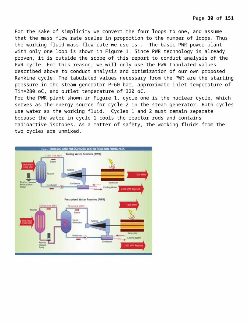
Page 30 of 107
From the Appendix in Fundamentals of Engineering Thermodynamics: h1 = 2952.6 kJ/kg, s1 = 6.1846 kJ/kg K.
equation (11) gives s2s = 6.1846 kJ/kg K. This entropy is equal to sg(30 bar). Thus, p2 = 30 bar and h2s = hg(30 bar) = 2804.2 kJ/kg. Equation (12) gives the entropy at state 2
0.85=2952.6−h2
2952.6−2804.2
This gives h2 = 2826.46 kJ/kg. The work done by turbine one is calculated from equation (14)
W t 1
m=(2952.6−2826.46 )=126.14 kJ/kg
The work done by turbine 2 is calculated from equation (15)
W t 2
m=110000
132.6−126.14=703.42 kJ/kg
h3 is found from equation (16)
h3=h (T1 , p2 )=3015.40 kJ/kg
Enthalpy at state four is found from equation (17)
h4=3015.40−703.42=2311.98 kJ/kg
Enthalpy at state 4s is found from equation (18)
0.85=3015.40−2311.983015.40−h4 s
which gives h4s = 2187.85 kJ/kg. Pressure at state 4 is chosen to be 1.5 bar. Thus, h5 is obtained by equation (19), which gives h5 = 467.11 kJ/kg. Equation (23) gives h6s
h6 s=467.11+1.0528∗10−3 (60−1.5 )∗100=473.36 kJ/kg
The enthalpy at state 6 is given by equation (20)
0.85=473.36−467.11h6−467.11
which gives h6 = 474.36 kJ/kg. Finally, equations (24) and (25) allow us to solve for the mass flow rates
mf +mout=3500
0=132.6 (2311.98−467.11 )+3500∗125.79−2676.1∗mf−167.57∗mout
These two equations yield mf = 29.94 kg/s and mout = 3470.76 kg/s
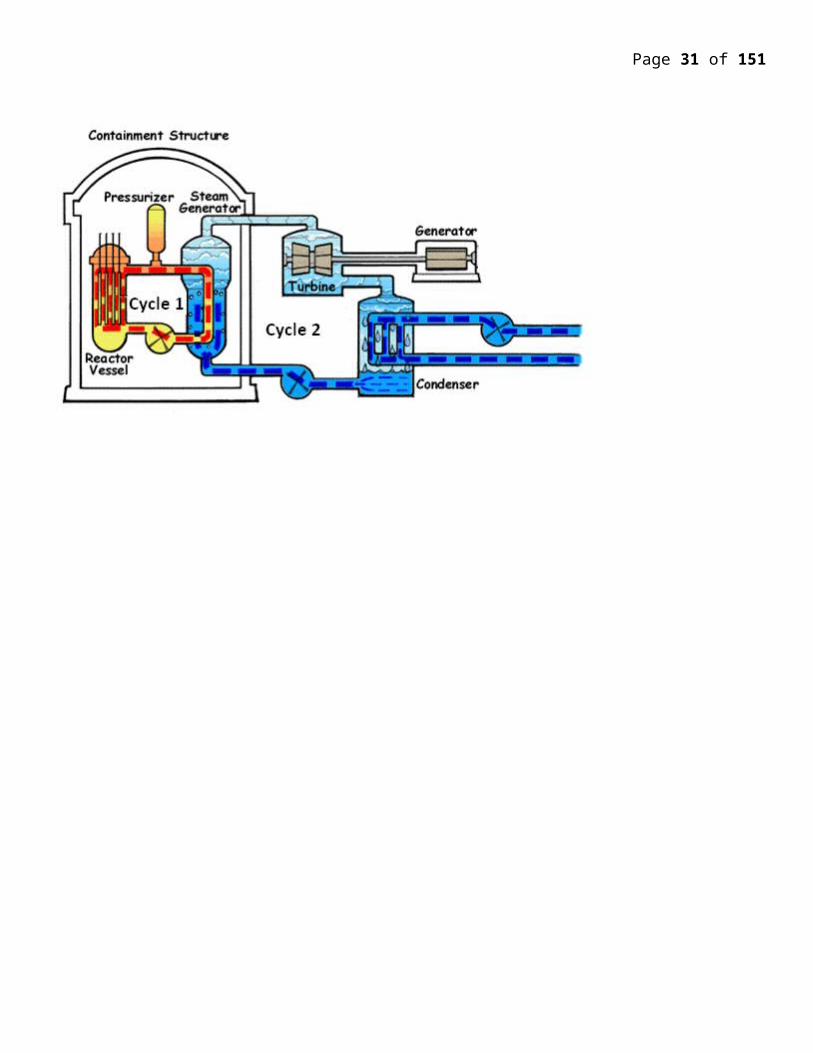
Page 31 of 107
Table 2– Equation of state values of Rankine cycle without reheat, shown in Figure 2
P2=1.5 bar
State Temperature (°C) Pressure (bar) Enthalpy kJ/kg
1 320 60 2952.6
2 111.4 1.5 2123.04
3 111.4 1.5 467.11
4 275.6 60 474.36
P2=2.5 bar
State Temperature (°C) Pressure (bar) Enthalpy kJ/kg
1 320 60 2952.6
2 127.4 2.5 2123.04
3 127.4 2.5 535.37
4 275.6 60 542.59
P2=5 bar
State Temperature (°C) Pressure (bar) Enthalpy kJ/kg
1 320 60 2952.6
2 151.9 5 2123.04
3 151.9 5 640.23
4 275.6 60 647.29
P2=7 bar
State Temperature (°C) Pressure (bar) Enthalpy kJ/kg
1 320 60 2952.6
2 165 7 2123.04
3 165 7 697.22
4 275.6 60 704.13
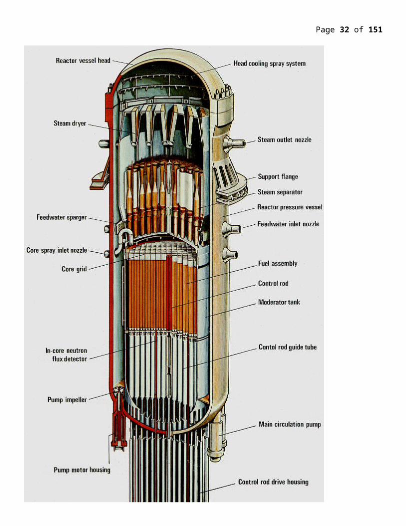
Page 32 of 107
P2=10 bar
State Temperature (°C) Pressure (bar) Enthalpy kJ/kg
1 320 60 2952.6
2 179.9 10 2123.04
3 179.9 10 762.81
4 275.6 60 769.44
P2=15 bar
State Temperature (°C) Pressure (bar) Enthalpy kJ/kg
1 320 60 2952.6
2 198.3 15 2123.04
3 198.3 15 844.84
4 275.6 60 850.95
Table 3 – Equation of state values for Rankine cycle with reheat, shown in Figure 3
p4 = 1.5 bar
state Temp (°C) pressure (bar) enthalpy (kJ/kg)
1 320 60 2952.6
2 233.9 30 2778.01
2s 233.9 30 2804.2
3 320 30 3015.4
4 111.4 1.5 2311.98
4s 111.4 1.5 2187.85
5 111.4 1.5 467.11
6 275.6 60 474.36
6s 275.6 60 473.27
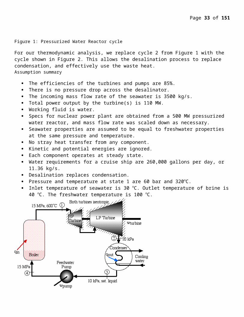
Page 33 of 107
p4 = 2.5 bar
state temp (°C) pressure (bar) enthalpy (kJ/kg)
1 320 60 2952.6
2 233.9 30 2778.01
2s 233.9 30 2804.2
3 320 30 3015.4
4 127.4 2.5 2311.98
4s 127.4 2.5 2187.85
5 127.4 2.5 535.37
6 275.6 60 542.59
6s 275.6 60 541.51
p4 = 5 bar
state temp (°C) pressure (bar) enthalpy (kJ/kg)
1 320 60 2952.6
2 233.9 30 2778.01
2s 233.9 30 2804.2
3 320 30 3015.4
4 151.9 5 2311.98
4s 151.9 5 2187.85
5 151.9 5 640.23
6 275.6 60 647.3
6s 275.6 60 646.24
p4 = 7 bar
state temp (°C) pressure (bar) enthalpy (kJ/kg)
1 320 60 2952.6
2 233.9 30 2778.01
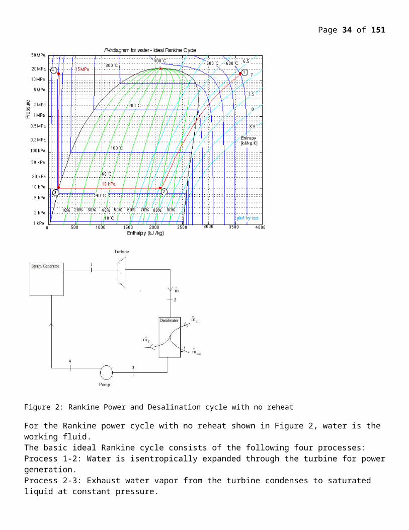
Page 34 of 107
2s 233.9 30 2804.2
3 320 30 3015.4
4 165 7 2311.98
4s 165 7 2187.85
5 165 7 697.22
6 275.6 60 704.13
6s 275.6 60 703.09
p4 = 10 bar
state temp (°C) pressure (bar) enthalpy (kJ/kg)
1 320 60 2952.6
2 233.9 30 2778.01
2s 233.9 30 2804.2
3 320 30 3015.4
4 179.9 10 2311.98
4s 179.9 10 2187.85
5 179.9 10 762.81
6 275.6 60 769.44
6s 275.6 60 768.45
p4 = 15 bar
state temp (deg C) pressure (bar) enthalpy (kJ/kg)
1 320 60 2952.6
2 233.9 30 2778.01
2s 233.9 30 2804.2
3 320 30 3015.4
4 198.3 15 2311.98
4s 198.3 15 2187.85
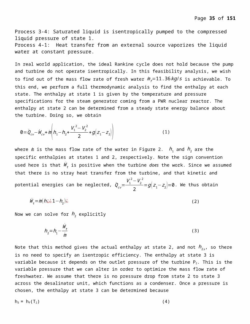
Page 35 of 107
5 198.3 15 844.84
6 275.6 60 850.95
6s 275.6 60 850.03
Table 4 – Freshwater mass flow rate optimization data for Rankine cycle without Reheat
Pressure (bar) ṁf (kg/s) ṁout (kg/s)
1.5 29.24 3470.76
2.5 25.63 3474.37
5 20.09 3479.91
7 17.08 3482.92
10 13.66 3486.34
15 9.27 3490.73
Table 5 – Freshwater mass flow rate optimization data for Rankine cycle with Reheat
Pressure (bar) ṁf (kg/s) ṁout (kg/s)
1.5 29.24 3470.76
2.5 25.63 3474.37
5 20.09 3479.91
7 17.08 3482.92
10 13.66 3486.34
15 9.27 3490.73
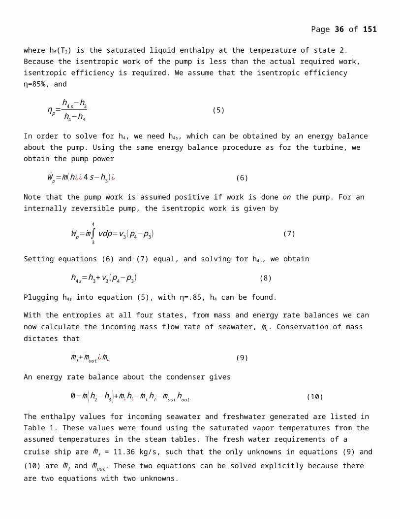
Page 36 of 107
0 2 4 6 8 10 12 14 1605
1015202530354045
f(x) = 0.0838734728444513 x² − 2.79795929616448 x + 32.584648493105
f(x) = 0.0844967741295136 x² − 2.809240891541 x + 42.5977401825674
Freshwater mass flow rate vs desalination pressure
With Regeneration
Polynomial (With Regenera-tion)
No Regeneration
Polynomial (No Regeneration)
Desalination Pressure (bar)
Fres
hwat
er m
ass fl
ow ra
te (k
g/s)
Figure 4 – Optimization of freshwater mass flow rate by using various desalination pressures
Discussion
After applying a polynomial trend line fit to the plots shown in Figure 4, we obtain the equation mf = .0839p2 – 2.798p +
32.585 for the basic cycle and mf = 0.0845p2 - 2.8092p + 42.598 for the reheat cycle. The optimal pressure can now be found by setting both these equations equal to 11.36 and solving for p. After solving we obtain Poptimal= 11.67 bar for the basic cycle. The reheat cycle does not have a solution for mf =11.36 kg/s, so the optimal pressure is simply the one that
gives the lowest mf , or Poptimal=15 bar, which yields mf =19.26 kg/s. These are both reasonable pressures to operate at. The greater mass flow rate of the reheat cycle would allow the desalinator to operate fewer hours per day, saving on maintenance costs.
According to our analysis, a nuclear powered cruise ship with desalination is possible. A reheat cycle would be more desirable due to the greater mass flow rate of freshwater; however, a basic cycle can also be used in order to save on capital costs. A major hurdle to overcome is the regulation that would be inevitable in this field. Furthermore, nuclear power plants have a negative perception in the media and much of the public, so an advertising campaign would most likely be necessary.
Lastly there are a few technical hurdles involved in building a nuclear powered cruise ship with desalination. We assumed that the incoming mass flow rate of the seawater was 3500 kg/s. This is a large amount water, but it is not impossible to achieve. We propose multiple large, industrial pumps, such as the QH pump made by Iron Pump, which has a capacity of 1100 kg/s and is built to operate in marine environments. Moreover, the natural pressure gradient between the interior of the ship and the ocean can help solve the large pumping requirements. In our analysis, we chose 15 bar as the maximum pressure in the desalinator. This was done for two reasons. Firstly, commercial pumps such as the QH cannot operate at pressures beyond this. Secondly, pressures above 15 bar yield temperatures above 200oC, which can damage pipes. A major issue affecting desalination plants is corrosion of pipes because of the seawater. The Waterfields desalination plant in the Bahamas had 316L stainless steel pipes, which began to show corrosion after only 6 months. The replacement was an AL-6XN alloy pipe, which has not corroded for over 10 years. We plan to use this material for all of our pipes in the desalinator such that no corrosion will take place.
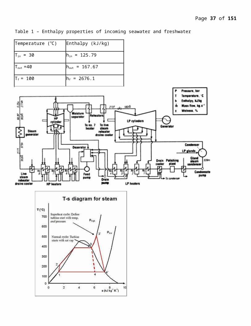
Page 37 of 107
Nuclear-Powered Ships
Nuclear power is particularly suitable for vessels which need to be at sea for long periods without refueling, or for powerful submarine propulsion. Some 140 ships are powered by more than 180 small nuclear reactors and more than 12,000 reactor years of marine operation has been accumulated. Most are submarines, but they range from icebreakers to aircraft carriers. In future, constraints on fossil fuel use in transport may bring marine nuclear propulsion into more widespread use. So far, exaggerated fears about safety have caused political restriction on port access. Work on nuclear marine propulsion started in the 1940s, and the first test reactor started up in USA in 1953. The first nuclear-powered submarine, USS Nautilus, put to sea in 1955. This marked the transition of submarines from slow underwater vessels to warships capable of sustaining 20-25 knots submerged for weeks on end. The submarine had come into its own.Nautilus led to the parallel development of further (Skate-class) submarines, powered by single pressurized water reactors, and an aircraft carrier, USS Enterprise, powered by eight reactor units in 1960. A cruiser, USS Long Beach, followed in 1961 and was powered by two of these early units. Remarkably, the Enterprise remains in service.By 1962 the US Navy had 26 nuclear submarines operational and 30 under construction. Nuclear power had revolutionized the Navy. The technology was shared with Britain, while French, Russian and Chinese developments proceeded separately.After the Skate-class vessels, reactor development proceeded and in the USA a single series of standardized designs was built by both Westinghouse and GE, one reactor powering each vessel. Rolls Royce built similar units for Royal Navy submarines and then developed the design further to the PWR-2. Russia developed both PWR and lead-bismuth cooled reactor designs, the latter not persisting. Eventually four generations of submarine PWRs were utilized, the last entering service in 1995 in the Severodvinsk class.The largest submarines are the 26,500 tonne Russian Typhoon-class, powered by twin 190 MWth PWR reactors, though these were superseded by the 24,000 t Oscar-II class (eg Kursk) with the same power plant. The safety record of the US nuclear navy is excellent, this being attributed to a high level of standardization in naval power plants and their maintenance, and the high quality of the Navy's training program. However, early Soviet endeavors resulted in a number of serious accidents - five where the reactor was irreparably damaged, and more resulting in radiation leaks. However, by Russia's third generation of marine PWRs in the late 1970s safety and reliability had become a high priority. Lloyd's Register shows about 200 nuclear reactors at sea, and that some 700 have been used at sea since the 1950s.
Nuclear Naval Fleets
Russia built 248 nuclear submarines and five naval surface vessels (plus 9 icebreakers) powered by 468 reactors between 1950 and 2003, and was then operating about 60 nuclear naval vessels.At the end of the Cold War, in 1989, there were over 400 nuclear-powered submarines operational or being built. At least 300 of these submarines have now been scrapped and some on order cancelled, due to weapons reduction programs*. Russia and USA had over one hundred each in service, with UK and France less than twenty each and China six. The total today is understood to be about 130, including new ones commissioned. In 2007 Russia had about 40 retired subs from its Pacific fleet alone awaiting scrapping. In November 2008 it was reported that Russia intended to scrap all decommissioned nuclear submarines by 2012, the total being mor
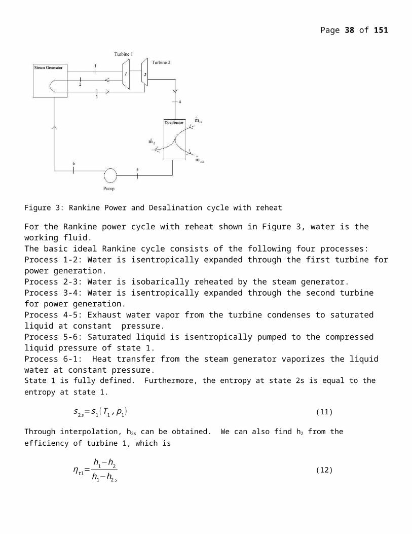
Page 38 of 107
e than 200 of the 250 built to date. Most Northern Fleet submarines had been dismantled at Severodvinsk, and most remaining to be scrapped were with the Pacific Fleet. India launched its first submarine in 2009, the 6000 dwt Arihant SSBN, with a single 85 MW PWR driving a 70 MW steam turbine. It is reported to have cost US$ 2.9 billion, and several more are planned. India is also leasing an almost-new 7900 dwt (12,770 tonne submerged) Russian Akula-II class nuclear attack submarine for ten years from 2010, at a cost of US$ 650 million: the Chakra, formerly Nerpa. It has a single 190 MWt VM-5/ OK-650 PWR driving a 32 MW steam turbine and two 2 MWe turbogenerators. The USA has the main navy with nuclear-powered aircraft carriers, while both it and Russia have had nuclear-powered cruisers (USA: 9, Russia 4). The USA had built 219 nuclear-powered vessels to mid 2010, and then had five submarines and an aircraft carrier under construction. All US aircraft carriers and submarines are nuclear-powered.The US Navy has accumulated over 6200 reactor-years of accident-free experience over the course of 230 million kilometres, and operated 82 nuclear-powered ships (11 aircraft carriers, 71 submarines - 18 SSBN/SSGN, 53 SSN) with 103 reactors as of March 2010.
The Russian Navy has logged over 6000 nautical reactor-years. It appears to have eight strategic submarines (SSBN/SSGN) in operation and 13 nuclear-powered attack submarines (SSN), plus some diesel subs. Russia has announced that it will build eight new nuclear SSBN submarines in its plan to 2015. Its only nuclear-powered carrier project was cancelled in 1992. It has one nuclear powered cruiser in operation and three others being overhauled.
France has a nuclear-powered aircraft carrier and ten nuclear submarines (4 SSBN, 6 Rubis class SSN). The UK has 12 submarines, all nuclear powered (4 SSBN, 8 SSN). China is understood to have about ten nuclear submarines (possibly 3 SSBN, 7 SSN). Several trends may end up shaping the future of naval ship technology: the all electrical ship, stealth technology, littoral vessels and moored barges for power production.
The all-electric ship propulsion concept was adopted for the future surface combatant power source. This next evolution or Advanced Electrical Power Systems, AEPS, involves the conversion of virtually all shipboard systems to electric power; even the most demanding systems, such as propulsion and catapults aboard aircraft carriers. It would encompass new weapon systems such as modern electromagnetic rail-guns and free electron lasers under development.
An all-electric ship is the CVN-21 next-generation USA Navy aircraft carrier, scheduled for launch around 2011-2013 to replace the then half-century-old USS Enterprise CVN 65. The CVN-21's new nuclear reactor not only will provide three times the electrical output of current carrier power plants, but also will use its integrated power system to run an Electro Magnetic Aircraft Launch System, EMALS to replace the current steam-driven catapults, combined with an Electromagnetic Aircraft Recovery System, EARS.
Littoral vessels are designed to operate closer to the coastlines than existing vessels such as cruisers and destroyers. Their mission would be signal intelligence gathering, stealth insertion of Special Forces, mine clearance, submarine hunting and humanitarian relief. Unmanned Underwater Vehicles, UUVs, monitored by nuclear-powered Virginia-class submarines would use Continuous Active Sonar (CAS) arrays which release a steady stream of energy, the sonar equivalent of a flashlight would be used to as robots to protect carrier groups and turning attacking or ambushing submarines from being the hunters into being the hunted.
The largest experience in operating nuclear power plants since the late 1950s has been in nuclear marine propulsion, particularly aircraft carriers (Fig. 1) and submarines. The nuclear powered vessels comprise about 40 percent of the USA Navy's combatant fleet, including the entire sea based strategic nuclear deterrent. All the USA Navy’s operational submarines and over half of its aircraft carriers are nuclear powered.
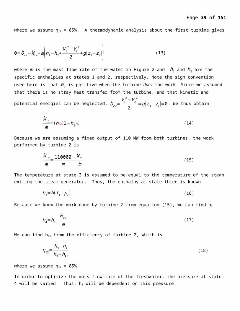
Page 39 of 107
The USA Navy had as of 10 Nimitz-class carriers, 1 Enterprise-class carrier; to be retired, 18 Ohio-class missile boats; 14 carrying ballistic missiles, and 4 armed with cruise missiles, 44 Los Angeles class attack submarines, and 3 Seawolf class attack submarines; including the signal intelligence and special forces insertion special warfare designed USS Jimmy Carter. As of 2008 it operated 99 vessels powered by nuclear reactors including 10 nuclear powered aircraft carriers and 71 submarines. It has operated nuclear powered ships for more than 50 years. As of 2001, about 235 naval reactors had been built at a unit cost of about $100 million for a submarine and $200 for an aircraft carrier.
The main considerations here are that nuclear powered submarines do not consume oxygen like conventional power plants, and that they have large endurance or mission times before fuel resupply, limited only by the available food and air purification supplies on board. Surface vessels equipped with nuclear plants have long refueling intervals and do not need to be accompanied by vulnerable fuel tankers.
By 2002, the USA Navy operated 53 attack submarines (SSN) and 18 ballistic missile submarines (SSBN). These used by 1999 about 129 nuclear reactors exceeding the number of commercial power plants at 108. The mission for nuclear powered submarines is being redefined in terms of signal intelligence gathering and special operations.
A nuclear reactor provides the submarine with a theoretical infinite submersion time. In addition, the high specific energy, or energy per unit weight of nuclear fuel, eliminates the need for constant refueling by fleets of vulnerable tankers following a fleet of surface or subsurface naval vessels. On the other hand, a single refueling of a nuclear reactor is sufficient for long intervals of time.
Newer designs use jet pump propulsion instead of propellers, and aim at an all electrical system design, including the weapons systems such as electromagnetic guns.
Marine reactors used for power supply
A marine reactor was used to supply power (1.5 MWe) to a US Antarctic base for ten years to 1972, testing the feasibility of such air-portable units for remote locations.
Russia has under construction at Severodvinsk the first of a series of floating power plants for their northern and far eastern territories. Two OKBM KLT-40S reactors derived from those in icebreakers, but with low-enriched fuel (less than 20% U-235), will be mounted on a 21,500 tonne, 144 m long barge. Refuelling interval is 3-4 years on site, and at the end of a 12-year operating cycle the whole plant is returned to a shipyard for a 2-year overhaul and storage of used fuel, before being returned to service.
{Nuclear aircraft carrier USS Theodore Roosevelt, Nimitz Class CVN71, powered with two with about 100 MW each, (A for Aircraft carrier, 4 for fourth generation and W for Westinghouse) nuclear reactors, crossing the Suez Canal, Egypt, during the first Gulf War, January 1991}
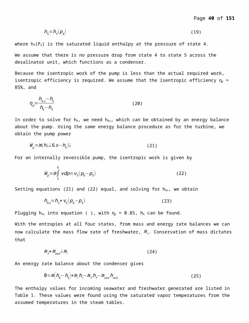
Page 40 of 107
Future prospectsWith increasing attention being given to greenhouse gas emissions arising from burning fossil fuels for international air and marine transport and the excellent safety record of nuclear powered ships, it is quite conceivable that renewed attention will be given to marine nuclear powered ships, it is likely that there will be renewed interest in marine nuclear propulsion.
The head of the large Chinese shipping company Cosco suggested in December 2009 that container ships should be powered by nuclear reactors in order to reduce greenhouse gas emissions from shipping. He said that Cosco is in talks with China's nuclear authority to develop nuclear powered freight vessels.
In 2010 Babcock International's marine division completed a study on developing a nuclear-powered LNG tanker. The study indicated that particular routes and cargoes lent themselves well to the nuclear propulsion option, and that technological advances in reactor design and manufacture had made the option more appealing.
In November 2010 the British Maritime classification society Lloyd's Register embarked upon a two-year study with US-based Hyperion Power Generation, British vessel designer BMT Group, and Greek ship operator Enterprises Shipping and Trading SA "to investigate the practical maritime applications for small modular reactors. The research is intended to produce a concept tanker-ship design," based on a 70 MWt reactor such as Hyperion's. Hyperion has a three-year contract with the other parties in the consortium, which plans to have the tanker design certified in as many countries as possible. The project includes research on a comprehensive regulatory framework led by the International Maritime Organisation (IMO), and supported by the International Atomic Energy Agency (IAEA) and regulators in countries involved. In response to its members' interest in nuclear propulsion Lloyd's Register has recently rewritten its 'rules' for nuclear ships, which concern the integration of a reactor certified by a land-based regulator with the rest of the ship. Nuclear ships are currently the responsibility of their own countries, but none are involved in international trade. Lloyds expects to "see nuclear ships on specific trade routes sooner than many people currently anticipate."
Nuclear power seems most immediately promising for the following:
Large bulk carriers that go back and forth constantly on few routes between dedicated ports – eg China to South America and NW Australia. They could be powered by a reactor delivering 100 MW thrust.
Cruise liners, which have demand curves like a small town. A 70 MWe unit could give base-load and charge batteries, with a smaller diesel unit supplying the peaks.
Nuclear tugs, to take conventional ships across oceans
Some kinds of bulk shipping, where speed is essential.
Civil Vessels
Nuclear propulsion has proven technically and economically essential in the Russian Arctic where operating conditions are beyond the capability of conventional icebreakers. The power levels required for breaking ice up to 3 metres thick, coupled with refuelling difficulties for other types of vessels, are significant factors. The nuclear fleet has increased Arctic navigation from 2 to 10 months per year, and in the Western Arctic, to year-round.The icebreaker Lenin was the world's first nuclear-powered surface vessel (20,000 dwt) and remained in service for 30 years, though new reactors were fitted in 1970.
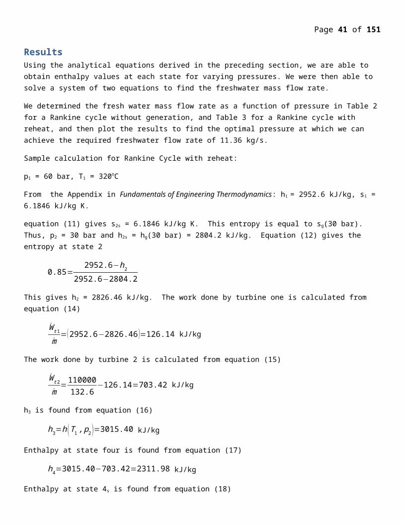
Page 41 of 107
It led to a series of larger icebreakers, the six 23,500 dwt Arktika-class, launched from 1975. These powerful vessels have two 171 MW OK-900 reactors delivering 54 MW at the propellers and are used in deep Arctic waters. The Arktika was the first surface vessel to reach the North Pole, in 1977. Rossija, Sovetskiy Soyuz and Yamal were in service towards the end of 2008, with Sibir decommissioned and Arktika retired in October 2008.
The seventh and largest Arktika class icebreaker - 50 Years of Victory (50 Let Pobedy) - was built by the Baltic shipyard at St Petersburg and after delays during construction it entered service in 2007 (twelve years later than the 50-year anniversary of 1945 it was to commemorate). It is 25,800 dwt, 160 m long and 20m wide, and is designed to break through ice up to 2.8 metres thick. Its performance in service has been impressive.
For use in shallow waters such as estuaries and rivers, two shallow-draft Taymyr-class icebreakers of 18,260 dwt with one reactor delivering 35 MW were built in Finland and then fitted with their nuclear steam supply system in Russia. They are built to conform with international safety standards for nuclear vessels and were launched from 1989.
Development of nuclear merchant ships began in the 1950s but on the whole has not been commercially successful. The 22,000 tonne US-built NS Savannah, was commissioned in 1962 and decommissioned eight years later. It was a technical success, but not economically viable. It had a 74 MWt reactor delivering 16.4 MW to the propeller. The German-built 15,000 tonne Otto Hahn cargo ship and research facility sailed some 650,000 nautical miles on 126 voyages in 10 years without any technical problems. It had a 36 MWt reactor delivering 8 MW to the propeller. However, it proved too expensive to operate and in 1982 it was converted to diesel.
The 8000 tonne Japanese Mutsu was the third civil vessel, put into service in 1970. It had a 36 MWt reactor delivering 8 MW to the propeller. It was dogged by technical and political problems and was an embarrassing failure. These three vessels used reactors with low-enriched uranium fuel (3.7 - 4.4% U-235).
In 1988 the NS Sevmorput was commissioned in Russia, mainly to serve northern Siberian ports. It is a 61,900 tonne 260 m long lash-carrier (taking lighters to ports with shallow water) and container ship with ice-breaking bow. It is powered by the same KLT-40 reactor as used in larger icebreakers, delivering 32.5 propeller MW from the 135 MWt reactor and it needed refuelling only once to 2003.
Russian experience with nuclear powered Arctic ships totalled 250 reactor-years in 2003. A more powerful icebreaker of 110 MW net and 55,600 dwt is planned, with further dual-draught ones of 32,400 dwt and 60 MW power at propellers. In 2008 the Arctic fleet was transferred from the Murmansk Shipping Company under the Ministry of Transport to Atomflot, under Rosatom.
The USA built one single nuclear merchant ship: the Savannah. It is shown in Fig.. It was designed as a national showpiece, and not as an economical merchant vessel. Figure 5 shows the design of its nuclear reactor. For compactness, the steam generators and steam drums surround the reactor core. This configuration also provides shielding for the crew. It was retired in 1970.
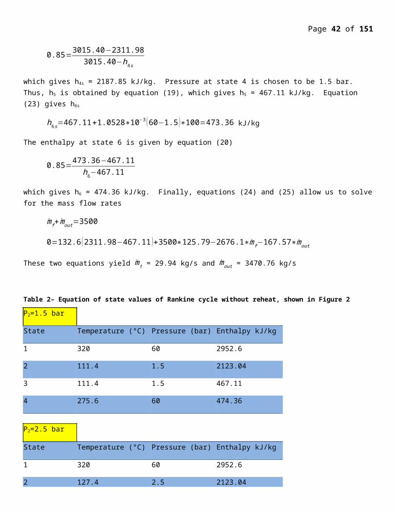
Page 42 of 107
The 630-A reactor, a low-power critical experiment, was operated at the Idaho National Laboratory (INL) to explore the feasibility of an air-cooled, water-moderated system for nuclear-powered merchant ships. Further development was discontinued in December 1964 when decisions were made to lower the priority of the entire nuclear power merchant ship program.
Nuclear Ice Breakers like the Russian Lenin and the Arktica were a good success, not requiring refueling in the arctic regions.
The Otto Hahn bulk ore carrier was built by Germany. It operated successfully for ten years.
The Mutsu was an oceanographic research vessel built in Japan in 1974. Due to a design flaw causing a radiation leakage from its top radiation shield, it never became fully operational.
The Sturgis MH-1A was a floating nuclear power plant ship (Fig. 6). It was carrying a 45 Megawatts Thermal (MWth) Pressurized water Reactor (PWR) for remote power supplies for the USA Army.
Decommissioning and Defueling
Dismantling decommissioned nuclear-powered submarines has become a major task for US and Russian navies. After defuelling, normal practice is to cut the reactor section from the vessel for disposal in shallow land burial as low-level waste. In Russia the whole vessels, or the sealed reactor sections, sometimes remain stored afloat indefinitely, though western-funded programs are addressing this and all decommissioned subs are due to be dismantled by 2012.
US Navy nuclear ships are decommissioned and defueled at the end of their useful lifetime, when the cost of continued operation is not justified by their military capability, or when the ship is no longer needed. The Navy faces the necessity of downsizing the fleet to an extent that was not envisioned in the 1980’s before the end of the Cold War. Most of the nuclear-powered cruisers will be removed from service, and some LOS ANGELES Class submarines are scheduled for removal from service as well. Eventually, the Navy will also need to decommission 0HIO Class submarines.
US Navy nuclear-powered ships are defueled during inactivation and prior to transfer of the crew. The defueling process removes the nuclear fuel from the reactor pressure vessel and consequently removes most of the radioactivity from the reactor plant. Defueling is an operation routinely accomplished using established processes at shipyards used to perform reactor servicing work.
A disposal method for the defueled reactor compartments is needed when the cost of continued operation is not justified by the ships’ military capability or when the ships are no longer needed. After a nuclear-powered ship no longer has sufficient military value to justify continuing to maintain the ship or the ship is no longer needed, the ship can be: (1) placed in protective storage for an extended period followed by permanent disposed or recycling; or (2) prepared for permanent disposd or recycling. The preferred alternative is land burial of the entire defueled reactor compartment at the Department of Energy Low Level Waste Burial Grounds at Hanford, Washington.
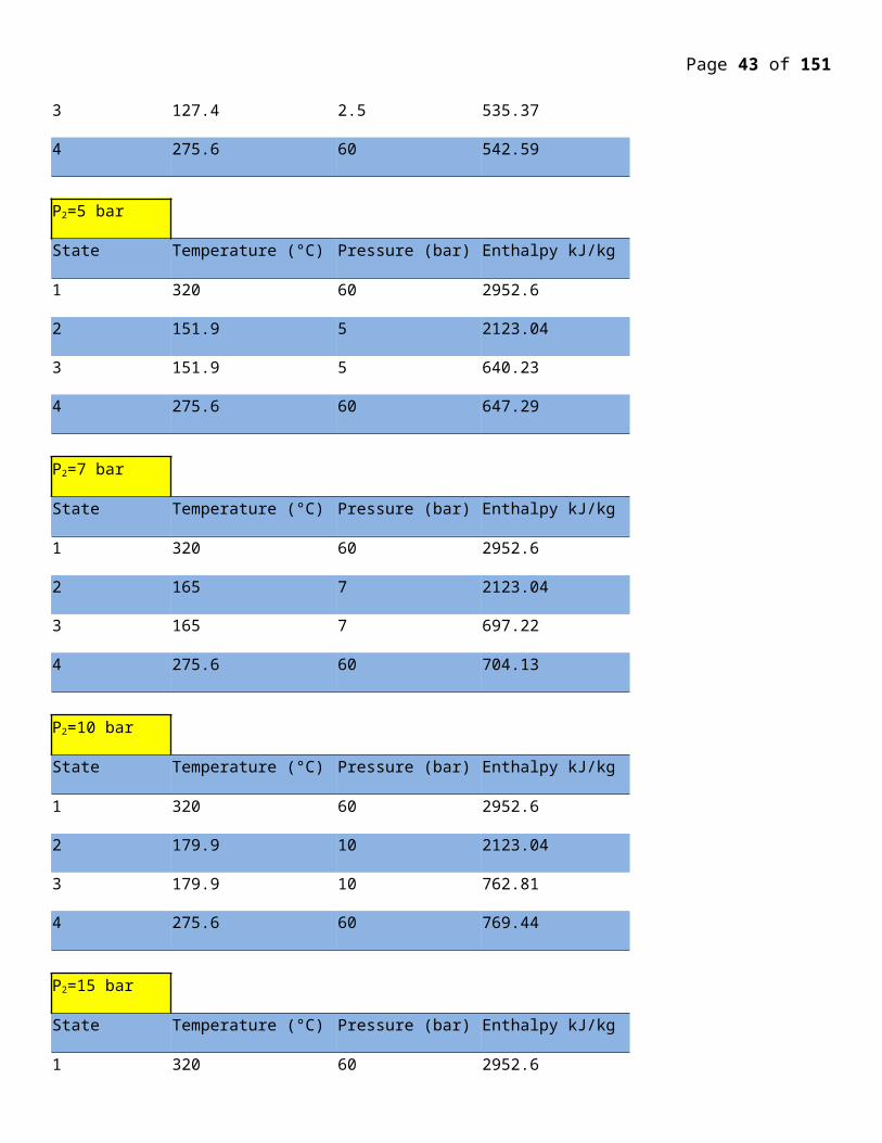
Page 43 of 107
A ship can be placed in floating protective storage for an indefinite period. Nuclear-powered ships can also be placed into storage for a long time without risk to the environment. The ship would be maintained in floating storage. About every 15 years each ship would have to be taken out of the water for an inspection and repainting of the hull to assure continued safe waterborne storage. However, this protective storage does not provide a permanent solution for disposal of the reactor compartments from these nuclear-powered ships. Thus, this alternative does not provide permanent disposal.
Before a ship is taken out of service, the spent fuel is removed from the reactor pressure vessel of the ship in a process called defueling. This defueling removes all of the fuel and most of the radioactivity from the reactor plant of the ships. The fuel removed from the decommissioned ships would be handed in the same manner as that removed from ships which are being refueled and returned to service. Unlike the low-level radioactive material in defueled reactor plants, the Nuclear Waste Policy Act of 1982, as amended, requires disposed of spent fuel in a deep geological repository.
Prior to disposal, the reactor pressure vessel, radioactive piping systems, and the reactor compartment disposed package would be sealed. Thus, they act as a containment structure for the radioactive atoms and delay the time when any of the radioactive atoms inside would be available for release to the environment as the metal corrodes. This is important because radioactivity decays away with time; that is, as time goes on radioactive atoms change into nonradioactive atoms. Since radioactivity decays away with time, the effect of a delay is that fewer radioactive atoms would be released to the environment. Over 99.9% of these atoms are an integral part of the metal and they are chemically just like ordinary iron, nickel, or other metal atoms. These radioactive atoms are only released from the metal as a result of the slow process of corrosion. The remaining O.1% which is corrosion and wear products -- decay away prior to penetration of the containment structures by corrosion.
The Hanford Site is used for disposal of radioactive waste from DOE operations. The pre-LOS ANGELES Class submarine reactor compartments are placed at the Hanford Site Low Level Burial Grounds for disposed, at the 218-E-12B burial ground in the 200 East area. The disposed of the reactor compartments from the cruisers, LOS ANGELES, and OHIO Class submarines would be consistent with the pre-LOS ANGELES Class submarine reactor compartment disposed program. The land required for the building of approximately 100 reactor compartments from the cruisers, LOS ANGELES, and OHIO Class submarines would be approximately 4 hectares (10 acres) which is similar to the land area needs for the pre-LOS ANGELES Class submarine reactor compartments.
An estimated cost for land burial of the reactor compartments is $10.2 million for each LOS ANGELES Class submarine reactor compartment, $12.8 million for each 0HIO Class submarine reactor compartment, and $40 million for each cruiser reactor compartment. The estimated total Shipyard occupational exposure to prepare the reactor compartment disposd packages is 13 rem (approximately 0.005 additiond latent cancer fatalities) for each LOS ANGELES Class submarine package, 14 rem (approximately 0.006 addtiond latent cancer fatalities) for each 0~0 Class submarine package and 25 rem (approximately 0.01 additiond latent cancer fatalities) for each cruiser package.
Nuclear power plant
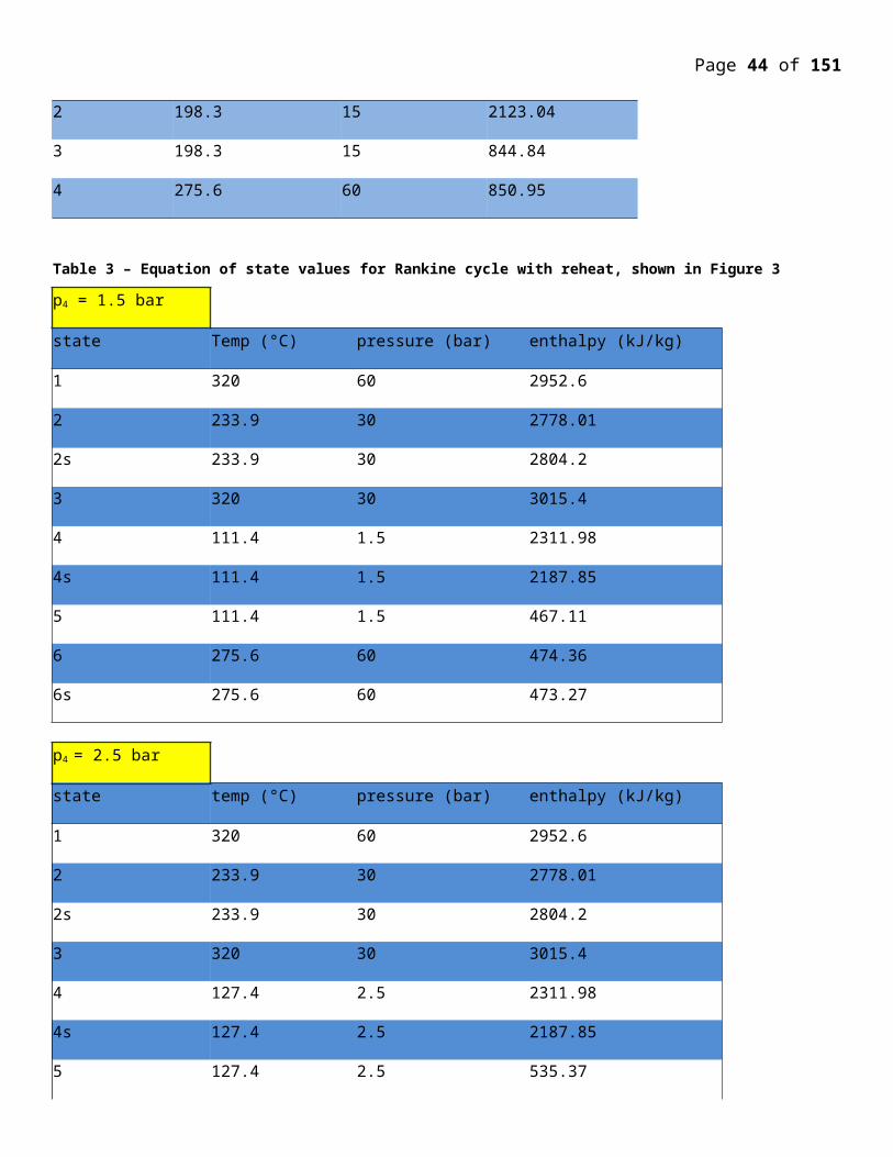
Page 44 of 107
The essential parts of a nuclear reactor (thermal or fast) are following
1.Fuel – combination of fertile and fissile material.
1 Fertile fuel are u238 and Th232
2 Fissile Fuel –U 233 ,U 235 and PU 239
2.Moderator – In thermal reactors(using slow neutrons) after moderation of MEV neutron to EV neutrons, fast neutrons are converted to slow for thermal neutrons
3.Core - contains fuel, moderator (if any)and control rods
4.Reflector – surrounds the core and reduces the neutron leakage
5.Containment vessel-prevents escape of radioactive fission products usually made of stainless steel
6.Shielding – prevents neutrons and gamma rays from escaping into the environment ,thereby causing harm to the escaping stuff
7.Coolant – removes heat from the core and transfers it to the water to generate steam .In some of the reactor ,coolent passes directly to the turbine such as boiling water and gas cooled reactors
8. Control system – Made from highly neutron absorbing material such as Boron or Cadmium .These rods are inserted into the core to lower the reaction rate and withdrawn to increase the power output.
9.Emergency system – Also includes evacuation means of Personal and citizens affected in the area of the power station.Many nuclear plants are unable to operation because of lak of proer ways to evacuation of people even though technically sound otherwise and license was granted but later with drawn after completion of power plant.
There are three types of reactors in worlds depending up on their intended purpose
Power generation
Research reactors
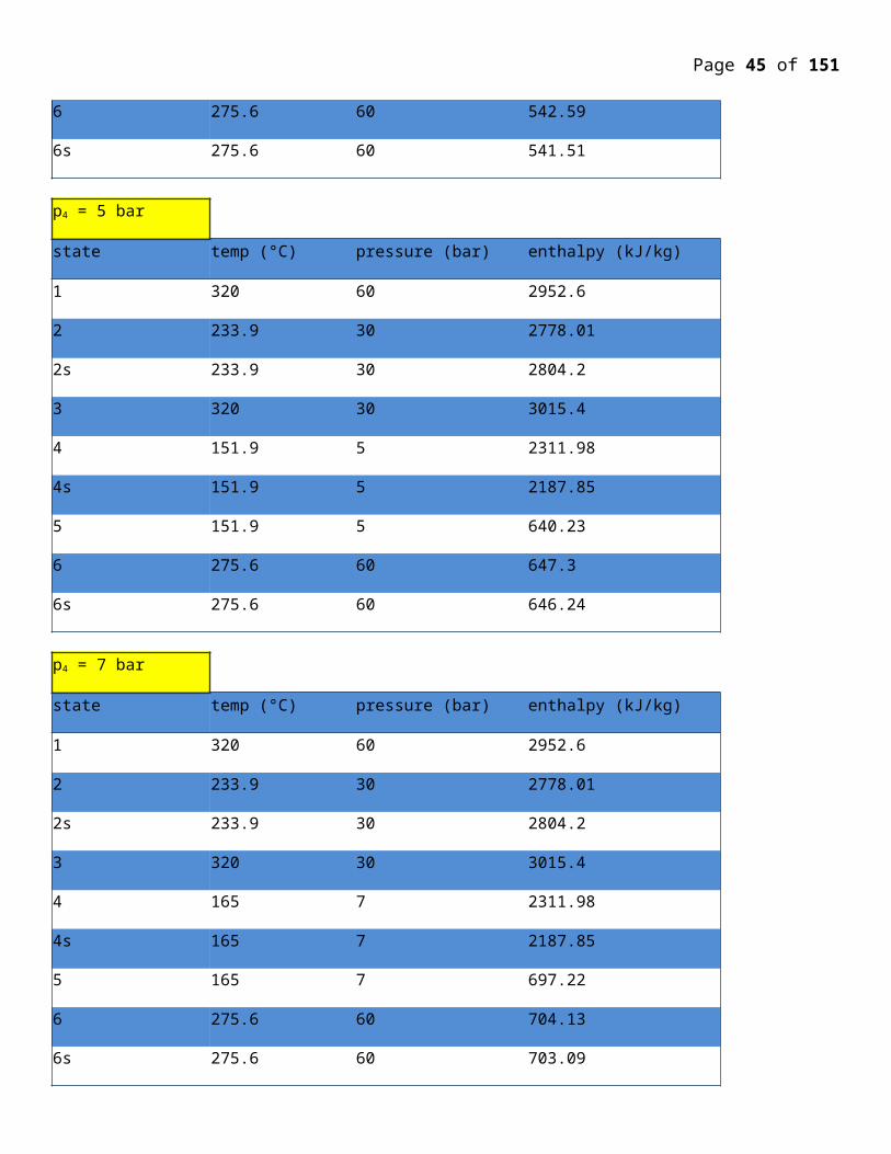
Page 45 of 107
Conversion reactors ( fast breeder reactors)
Power generation reactors are classified in five catagories viz
1. BWR ( Boiling Water Reactors)2. PWR ( Pressurised Water Reactors)3. CANDU ( Cadian deuterium (D2O))4. G C R (Gas Cooled reactors )5. LMFBR (Liquid metal fast breeder reactors)
Reactor:- The most important port of the nuclear plant is the reaction, with fusion technology still in its infancy the reactors are essentially of fission type which can essentially be divided into two type:-
(a) FAST BREEDER REACTOR:- These reactors use plutonium as fuel. Plutonium undergoes fission which a high a large speed neutrons strike it these reactors don't require any moderator other elements of this reactors are similar to thermonuclear reactors Fast reactors although not in much use at the present are gaining importance as try have many advantages over thermal reactors.
Fast reactors use plutonium which is produce artificially when U-238 atom absorbs a neutron this can be achieved by surrounding the core with a blankets of U-238 which is gradually converted to plutonium by bombardments with neutrons escaping from the core.
The uranium found in the earths crust is 99.3% U-238 and 0.7%U-235. Hence fast reactors enhanced the life of the fuel. For the same power output the fuel required would be less and hence the fast breeder reactors are much smaller in size than thermonuclear reactor since the size of the reactors is smaller for efficient that transfer metal coolant such as sodium is used.
(b) THERMONUCLEAR REACTOR:-This uses U-235 as fuel. The neutrons are liberated from the fission neutron. But the U-235;doe sent under go fission until a slow speed neutron strikes it. So neutrons liberated from the fission has to slowed by passing through some materials, called MODERATOR, before try strikes the U-235 atom. These slow neutrons are called thermal neutrons and the reactor concerned Thermal reactors or thermonuclear reactor. Depending upon the coolant, moderator, cladding used the rector can be further classified.
REACTOR DESIGN SAFETY FEATURES:- Particular points especially emphasized in design and the commercial safety are:-
1) No one in the control area shall be exposed to radiation exceeding hall the allowable limit the radiation shields are designed for the following conditions less than 0.5 rem/yr in the non controlled area, less than 5 rems/ year in controlled area, where any one can enter, except for inspection for a limited time. The reutilization system is divided into two sections, one for areas where radioactive.
Contamination may occur and another for areas where it never occurs inside the reactor container, the reactor room and reactor auxiliary rooms, the atmosphere is kept slight lower to avoid spread of inside air
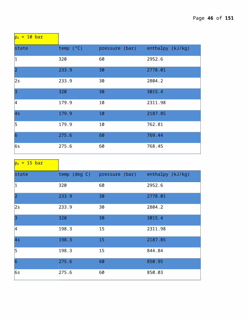
Page 46 of 107
2) Any hazard due to either mishandling by an operator or malfunction of control system shall be kept to a minimum instruments monitor. The condition of the reactor and its associated plant if these indicate a potentially dangerous situations or if all control electrical supplies, fail, the rod-drive motors de-energies and the reactor shuts down automatically.
3) The diffusion of radioactively shall be prevented by installing the reactor vessel and accessory instrumentation in a steel container, which also protests the reactor plants against free flooding. At the bottom of container two sets of pressure balancing valve are provided to present the rupture of the container by external pressure in the event of sinking. The valves open at pressure difference of 2 kg/cm2 so sea water can flow into the container and will close again after the divination of pressure difference.
4) The steel container should always be safe against such as collision or stranding being located in the center of the well and protected on all sides with reinforced structure. Three reactor itself, the reactor auxiliary equipment and the reactor service area forward of the machinery space are auxiliary rooms are equipped with anti-collision structure of uniform strength around the front and back of reactor. Both sides of these rooms re equipped with anti collision structure, which consists of six decks of thicker plates. In event of collision, the energy will be absorbed by this structure, thus not damaging the container and the installations in the reactor and it’s a built up lattice composed of stranding, this structure will protect the inner bottom plate against breakages and two protect the reactor container and other installation.
5) The two – compartment standard and strict stability criteria will be applied to prevent an eventual foundering
6) Fireproof constructions, fire detecting system and fore extinguishing systems are to be sufficiently installed throughout the ship, non-combustible materials are to be used for furnishing.
7) Dust type installations and the principal of dispersal are adopted to ensure the security of functioning of all equipment. For safe and smooth operation, it is important that all the important parts in the primary circuit duplicated so that if one of them fail other can take over the charge.
8) Emergency devices and the safety systems associated with reactor plant shall operate satisfactorily when subjected to the following:-
Roll 600 – single amplitude
Pitch 200 – single amplitude
List 600 – Trim – 200
Vertical acceleration: 1+1.3g, other ascertain – 1.0 g
This is conversion reactors converts U238 in to Pu239 and Th232 into U233
Figure 1 to 5 show schematic sketches of five important reactors used in the world for power generation
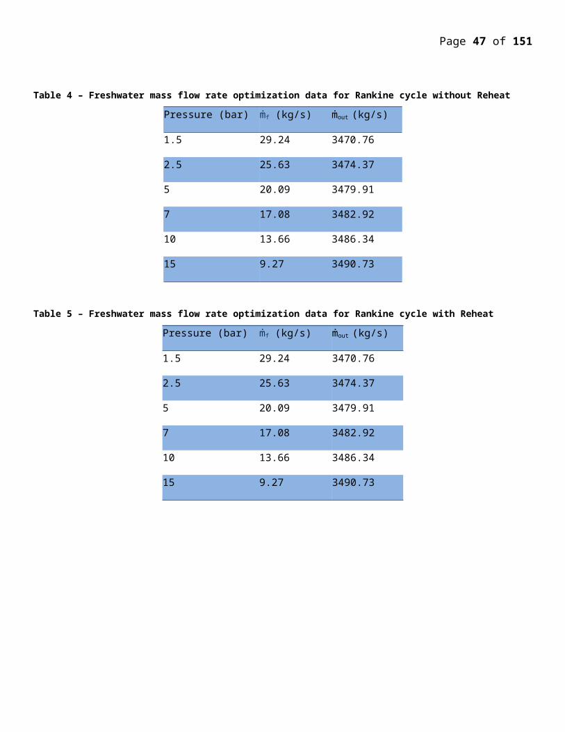
Page 47 of 107
Marine power plantsA nuclear-powered ship is constructed with the nuclear power plant inside a section of the ship called the reactor compartment. The components of the nuclear power plant include a high-strength steel reactor vessel, heat exchanger(s) (steam generator), and associated piping, pumps, and valves. Each reactor plant contains over 100 tons of lead shielding, part of which is made radioactive by contact with radioactive material or by neutron activation of impurities in the lead.
The propulsion plant of a nuclear-powered ship or submarine uses a nuclear reactor to generate heat. The heat comes from the fissioning of nuclear fuel contained within the reactor. Since the fisioning process also produces radiation, shields are placed around the reactor so that the crew is protected.
Naval reactors (with the exception of the ill-fated Russian Alfa class described below) have been pressurised water types, which differ from commercial reactors producing electricity in that:
they deliver a lot of power from a very small volume and therefore run on highly-enriched uranium (>20% U-235, originally c 97% but apparently now 93% in latest US submarines, c 20-25% in some western vessels, 20% in the first and second generation Russian reactors (1957-81)*, then 45% in 3rd generation Russian units, 40% in India's Arihant).
the fuel is not UO2 but a uranium-zirconium or uranium-aluminium alloy (c15%U with 93% enrichment, or more U with less - eg 20% - U-235) or a metal-ceramic (Kursk: U-Al zoned 20-45% enriched, clad in zircaloy, with c 200kg U-235 in each 200 MW core),
they have long core lives, so that refuelling is needed only after 10 or more years, and new cores are designed to last 50 years in carriers and 30-40 years (over 1.5 million kilometres) in most submarines,
the design enables a compact pressure vessel while maintaining safety. The Sevmorput pressure vessel for a relatively large marine reactor is 4.6 m high and 1.8 m diameter, enclosing a core 1 m high and 1.2 m diameter.
thermal efficiency is less than in civil nuclear power plants due to the need for flexible power output, and space constraints for the steam system,
there is no soluble boron used in naval reactors (at least US ones).
* An IAEA Tecdoc reports discharge assay of early submarine used fuel reprocessed at Mayak being 17% U-235.
The long core life is enabled by the relatively high enrichment of the uranium and by incorporating a "burnable poison" such as gadolinium - which is progressively depleted as fission products and actinides accumulate. These accumulating poisons would normally cause reduced fuel efficiency, but the two effects cancel one another out.
The most common nuclear reactor a used in machine propulsion is pressurized water reactor. The reactor is fulled by UO2 uranium dioxide pellets with enriched to 4.4%encased in hollow stainless steel cylinders closed at both ends. The fuel contain B10 of born as a “burnable poison” introduced deliberately to reduce reactivity of the reactor core at the start of life. The fuel are held between two plates, secured by a control rod of Zircoloy. The control roads of Boron carbides in the steel are placed in reactor core. In cruciform cross section these control rods can be moved in or out of the core is space between the fuel element in the event of an emergency there is a spring drive action for inserting the rods into the core. Thermal shields protect the pressure vessel walls from the heating effects of direct radiation from the core the pressure vessels wall in protected from direct radiation and the resulting our heating by a series of thermal shields around the core barrel these thermal shields build to reduce the radiation level outside the reactor and are
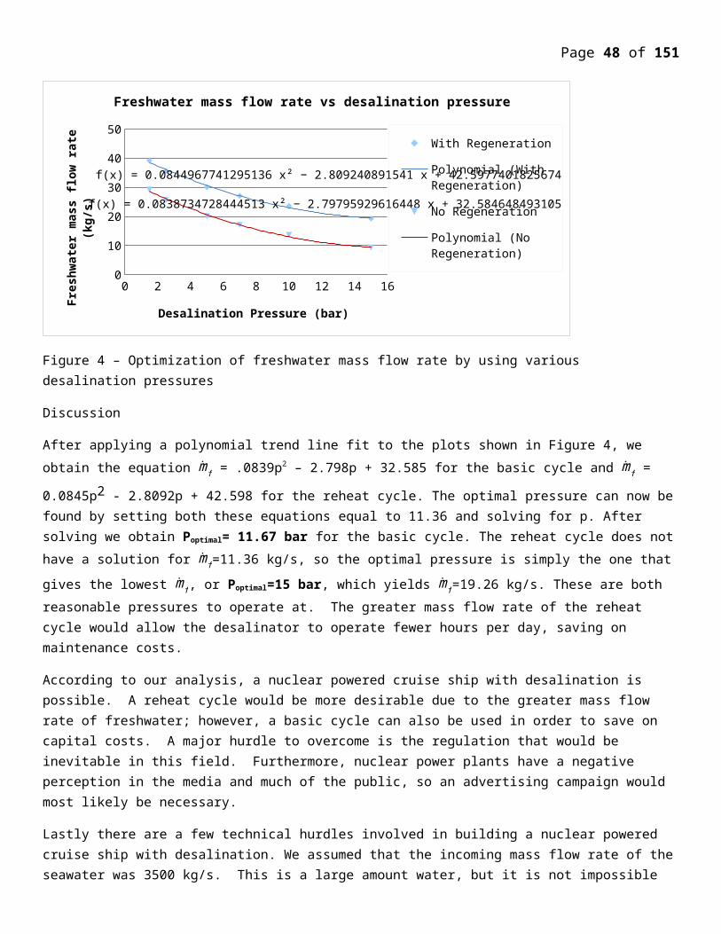
Page 48 of 107
supplement by a primary shield tank the entire reactor assembly is enclosed in an isolable steel containment vessel the containment vessel protects the ship and her crew against the most serious conceivable reactor accident and also shields working area from radiation while the reactor is working the main shielding is done by a secondary shield of a lead face tank around the reactor pressure vessel which is enclosed within concrete wall 2'(fleet) thick. This tank
provides a layers of water 33”thick to absorb neutrons while the lead surface attenuates the γ(gamma) radiation. A secondary shields in formed by lead, polythene and concrete around the containment used the shielding has been designed to reduced the radiation level in the living areas of the ship to less than 0.5 rems a year, while in actual practice the actual exposure among the crew has in fact has been under 0.2 rems a year.
In a pressurized water reactor water of a very high purity is used as both moderator and coolant. Heat from the nuclear fission of the U-235 atoms in the reactor core is transferred to the steam generators which are essentially shell and tube type that exchanger, by circulating the water moderator from the pressure vessel through two primary lines. The stainless steel of the primary circuit are susceptible to salt water corrosion while corrosion from the dissolved oxygen in also aggravated by the strong radioactive field in which the primary circuit components operate. Water purity is maintained by the careful control of the water added to the primary circuit to make up losses and by circulating a portion of the coolant through the filters in parallel with main circuit. Each loop includes two circulating pumps and each can operate independently so that one loop may be isolated and operation continue in one steam generator alone if there is a component failure or a coolant leak. An emergency pump in each coolant loop coolant flow in case of main pump failure. If both loop fails the reactor is shutdown automatically.
The primary water is maintained of an average pressure of 1735 psi≈115.7 bars, the reactor core temperature is well below the boiling points at all normal temperature in the reactor system. This is is maintained by an independent pressurizer connected to the primary circuit the pressurizer pressure is held 1,735lb/in2 by operating electric water and spray control to keep the water in the pressurizer vessel boiling at a temperature corresponding to the required saturation vapor pressure. The pressurizer also serves as a reservoir for of water to compensate for volume change in the primary circuit. The primary coolant should be prevented from boiling within containment vessel since the steam has lower heat capacity than water, & if steam enters reactor coolant pump cavitation would cause loss of circulation.
Since the reactor cooling water is prevented from boiling in the reactor core the steam needed for the propulsion turbine is produced in a externally in heat exchanger of shall and tube type with the coolant passing through the types while the outside surfaces of the tubes are in contact with the feed water circulated for what is basically a conventional steam plant. The feed water boils in the heat exchanger producing high quality wet steam. The stem is separated in cyclone steam separators to give dry saturated steam for turbines.
The use of water as moderator and coolant has certain advantages of being self-stabilizing type. The principal controlling force any pressurized water reactor is the coolant temperature. If the power demand increases, heat is extracted from the steam generator at a greater rate due to increase in demand, then temperature of the primary coolant at the outlet generators will fall. The temperature decrease will increase the density and the moderating efficiency of the water entering the reactor vessel the reactor power output will increase and so the temperature at the reactor outlet (and the steam generator inlet) will increase. The density changes in the primary coolant thus automatically adjust the reactivity and the temperature across the steam generators to meet the power demand. This self controlling property is one of the most important features of the pressurized water reactor making it highly suitable for marine propulsion.
At normal operating temperatures, the reactor is effectively controlled by adjusting the circulating pump power to maintain the average temperature of the primary coolant constant the coolant temperature changes are sufficient to control the reactivity of the core during the normal operation, but must be assisted by control rod movement during
Page 49 of 107
large or sudden changer in the power demand and also to compensate for gradual consumption of fuel and to compensate for generator and delay of neutron absorbing poison while the reactor is operating they are also needed at the start-up and shutdown and also must be capable of quick withdrawal for rapid start-up.
The reactor crown is spherical and the top from a cupola to give enough space for control rod driving mechanism it is made of high tensile steel of 60mm thickness. The control rod shafts protrude through the pressure vessel load are attached to treaded lead screws, rollers nuts on the rotor segments mesh with the lead screw, when the rotors are attached by the magnetic field of the energized stators. When the stators are energized from a stepped D.C source the magnetic field and hence rotors and roller nuts, rotate the leads screws travel along the roller nut to withdraw or insert the control rods. The rods are held by a fixed D.C. Voltage on the drive motor stators .In case of emergency the stators are unenergized the segment of the rotors forced a part by springs and the lead screws are released so that rods are drives into core by gravity and by springs.
The stepped D.C. that supplies the drive motors are derived from solid stare circuits and controlled from the reactor control console, so that rode may be moved singly or in groups as the operator desires and the same is displayed on the meters on the console.
Electrical power for the reactors control system and for the normal electrical services of the slip coils from the steam-driver turbo alternators. When the reactors are shutdown the necessary supplies are maintained by auxiliary diesel generators,while a secondary battery ensure that the vital services are powered even all generators are off load. An emergency diesel generators maintain essential supply while auxiliary generators are being then up Emergency generator should have capacity to supply the residual heat exchange steam or the safety injection systems with power under the conditions. Auxiliary generators should together be capable of starting the emergency propulsion systems if the reactor is suddenly shut down the auxiliary boiler may produce enough steam for the ship to turn at 10km when the reactor is not operating it is able to automatically the main turbine with steam within 15 minutes after reactor shutdown
However, the enrichment level for newer French naval fuel has been dropped to 7.5% U-235, the fuel being known as 'caramel', which needs to be changed every ten years or so. This avoids the need for a specific military enrichment line, and some reactors will be smaller versions of those on the Charles de Gaulle. In 2006 the Defence Ministry announced that Barracuda class subs would use fuel with "civilian enrichment, identical to that of EdF power plants," which may be an exaggeration but certainly marks a major change there.
Long-term integrity of the compact reactor pressure vessel is maintained by providing an internal neutron shield. (This is in contrast to early Soviet civil PWR designs where embrittlement occurs due to neutron bombardment of a very narrow pressure vessel.)
The Russian, US, and British navies rely on steam turbine propulsion, the French and Chinese in submarines use the turbine to generate electricity for propulsion.
Russian ballistic missile submarines as well as all surface ships since the Enterprise are powered by two reactors. Other submarines (except some Russian attack subs) are powered by one. A new Russian test-bed submarine is diesel-powered but has a very small nuclear reactor for auxiliary power.
The Russian Alfa-class submarines had a single liquid metal cooled reactor (LMR) of 155 MWt and using very highly enriched uranium - 90% enriched U-Be fuel. These were very fast, but had operational problems in ensuring that the lead-bismuth coolant did not freeze when the reactor was shut down. The design was unsuccessful and used in only eight trouble-plagued vessels.
Page 50 of 107
The US Navy's second nuclear submarine had a sodium-cooled power plant (S2G). The USS Seawolf, SSN-575, operated for nearly two years 1957-58 with this. The intermediate-spectrum reactor raised its incoming coolant temperature over ten times as much as the Nautilus' water-cooled plant, providing superheated steam, and it offered an outlet temperature of 454°C, compared with the Nautilus’ 305°C. It was highly efficient, but offsetting this, the plant had serious operational disadvantages. Large electric heaters were required to keep the plant warm when the reactor was down to avoid the sodium freezing. The biggest problem was that the sodium became highly radioactive, with a half-life of 15 hours, so that the whole reactor system had to be more heavily shielded than a water-cooled plant, and the reactor compartment couldn’t be entered for many days after shutdown. The reactor was replaced with a PWR type (S2Wa) similar to Nautilus.
Reactor power ranges from 10 MWt (in a prototype) up to 200 MWt in the larger submarines and 300 MWt in surface ships such as the Kirov-class battle cruisers.
The smallest nuclear submarines are the French Rubis-class attack subs (2600 dwt) in service since 1983, and these have a 48 MW integrated PWR reactor from Technicatome which is variously reported as needing no refueling for 30 years, or requiring refueling every seven years. The French aircraft carrier Charles de Gaulle (38,000 dwt), commissioned in 2000, has two K15 integrated PWR units driving 61 MW Alstom turbines and the system can provide 5 years running at 25 knots before refueling. The Le Triomphant class of ballistic missile submarines (12,640 dwt - the last launched in 2008) uses these K15 naval PWRs of 150 MWt and 32 shaft MW. The Barracuda class (4765 dwt) attack submarines, will have hybrid propulsion: electric for normal use and pump-jet for higher speeds. Areva TA (formerly Technicatome) will provide six reactors apparently of only 50 MWt and based on the K15 for the Barracuda submarines, the first to be commissioned in 2017. As noted above, they will use low-enriched fuel.
French integrated PWR system for submarine(steam generator within reactor pressure vessel)
British Vanguard class ballistic missile submarines of 15,800 t have a single PWR2 reactor with two steam turbines driving a single pump jet of 20.5 MW. New versions of this with "Core H" will require no refuelling over the life of the vessel*. UK Astute class attack subs of 7800t have a modified PWR2 reactor driving two steam turbines and a single pump jet variously reported as 11.5 or 20.5 MW, and are being commissioned from 2010. Russia's 19,400 tonne Oscar-II class has two 190 MWt reactors with steam turbines delivering 73 MW, and its 12,700 tonne Akula-II class has a single 190 MWt unit powering a 32 MW steam turbine.
* Rolls Royce claims that the Core H PWR2 has six times the (undisclosed) power of its original PWR1 and runs four times as long. The Core H is Rolls Royce's sixth-generation submarine reactor core.
Page 51 of 107
Russia's large Arktika class icebreakers use two OK-900A (essentially KLT-40) nuclear reactors of 171 MW each with 241 or 274 fuel assemblies of 45-75% enriched fuel and 3-4 year refueling interval. They drive steam turbines and each produces up to 33 MW at the propellers, though overall power is 54 MW. The two Tamyr class icebreakers have a single 171 MW KLT-40 reactor giving 35 MW propulsive power. Sevmorput uses one 135 MW KLT-40 unit producing 32.5 MW propulsive, and all those use 90% enriched fuel. (The now-retired Lenin's first OK-150 reactors used 5% enriched fuel but were replaced by OK-900 units with 45-75% enriched fuel.) Most of the Arktika-class vessels have had operating life extensions based on engineering knowledge built up from experience with Arktika itself. It was originally designed for 100,000 hours of reactor life, but this was extended first to 150,000 hours, then to 175,000 hours. In practice this equated to a lifespan of eight extra years of operation on top of the design period of 25. In that time, Arkitka covered more than 1 million nautical miles.
For the next generation of Russian icebreakers, integrated light water reactor designs are being investigated possibly to replace the conventional PWR. OKBM Afrikantov is developing a new icebreaker reactor – RITM-200 – to replace the current KLT reactors. This is an integral 210 MWt, 55 MWe PWR with inherent safety features. The first icebreaker to be equipped with this is due to start construction in 2010. For floating nuclear power plants (see below) a single RITM-200 would replace twin KLT-40S (but yield less power).
India's Arihant (6000 dwt) has an 85 MWe PWR using 40% enriched uranium driving a 35 MW steam turbine.
Brazil's navy is proposing to build an 11 MW prototype reactor by 2014 to operate for about eight years, with a view to a full-sized version using low-enriched uranium being in a submarine to be launched in 2021.
History of reactor design evolution
Initially, the General Electric (GE) Company was assigned to develop a liquid metal concept; and the Westinghouse Company, a pressurized water concept. Each company built an AEC-owned and -financed nuclear development laboratory. Westinghouse purchased the original site of the Allegheny County Airport in a suburb of Pittsburgh, Pennsylvania for what became known as the Bettis Atomic Power Laboratory. GE built the Knolls Atomic Power Laboratory in New York.
The Westinghouse program produced results first. Using pressurized water as the coolant showed how corrosive hot water could be on the metal cladding surrounding the fuel. Westinghouse discovered that pure zirconium resisted such corrosion. Westinghouse built its own facility to produce it. The pure metal initially formed the cladding for the fuel elements to be later replaced by a zirconium alloy, Zircaloy that improved its performance.
With a high enrichment level of 93 percent, capable of reaching 97.3 percent in U235, naval reactors, are designed for a refueling after 10 or more years over their 20-30 years lifetime, whereas land based reactors use fuel enriched to 3-5 percent in U235, and need to be refueled every 1-1 1/2 years period. New cores are designed to last 50 years in carriers and 30-40 years in submarines, which is the design goal of the Virginia class of submarines.
Burnable poisons such as gadolinium or boron are incorporated in the cores. These allow a high initial reactivity that compensates for the buildup of fission products poisons over the core lifetime, as well as the need to overcome the reactor dead time caused by the xenon poison changes as a result of operation at different power levels.

Page 52 of 107
Naval reactors use high burn up fuels such as uranium-zirconium, uranium-aluminum, and metal ceramic fuels, in contrast to land-based reactors which use uranium dioxide UO2. These factors provide the naval vessels theoretical infinite range and mission time. For these two considerations, it is recognized that a nuclear reactor is the ideal engine for naval propulsion.
A compact pressure vessel with an internal neutron and gamma ray shield is required by the design while maintaining safety of operation. Their thermal efficiency is lower than the thermal efficiency of land based reactors because of the emphasis on flexible power operation rather than steady state operation, and of space constraints.
Reactor powers range from 10 MWth in prototypes to 200 MWth in subsurface vessels, and 500 MWth in surface ships larger submarines.
Construction of the Nautilus (SSN-571) started on June 14, 1952, its first operation was on December 30, 1954 and it reached full power operation on January 13, 1955. It was commissioned in 1954, with its first sea trials in 1955. It set speed, distance and submergence records for submarine operation that were not possible with conventional submarines. It was the first ship to reach the North Pole. It was decommissioned in 1980 after 25 years of service, 2,500 dives, and a travelled distance of 513,000 miles. It is preserved at a museum at Croton, Connecticut.
Figure 3 shows the experimental setup S1W prototype for the testing of the Nautilus’s nuclear reactor built at the Idaho National Laboratory (INL) in 1989. The section of the hull containing the reactor rested in a “sea tank” of water 40 feet deep and 50 feet in diameter. The purpose of the water was to help shielding specialists study “backscatter,” radiation that might escape the hull, bounce off the water molecules, and reflect back into the living quarters of the ship.
The advantage of a nuclear engine for a submarine is that it can travel long distances undetected at high speed underwater avoiding the surface wave resistance, without refueling. Unlike diesel engine driven submarines, the nuclear engine does not need oxygen to produce its energy.
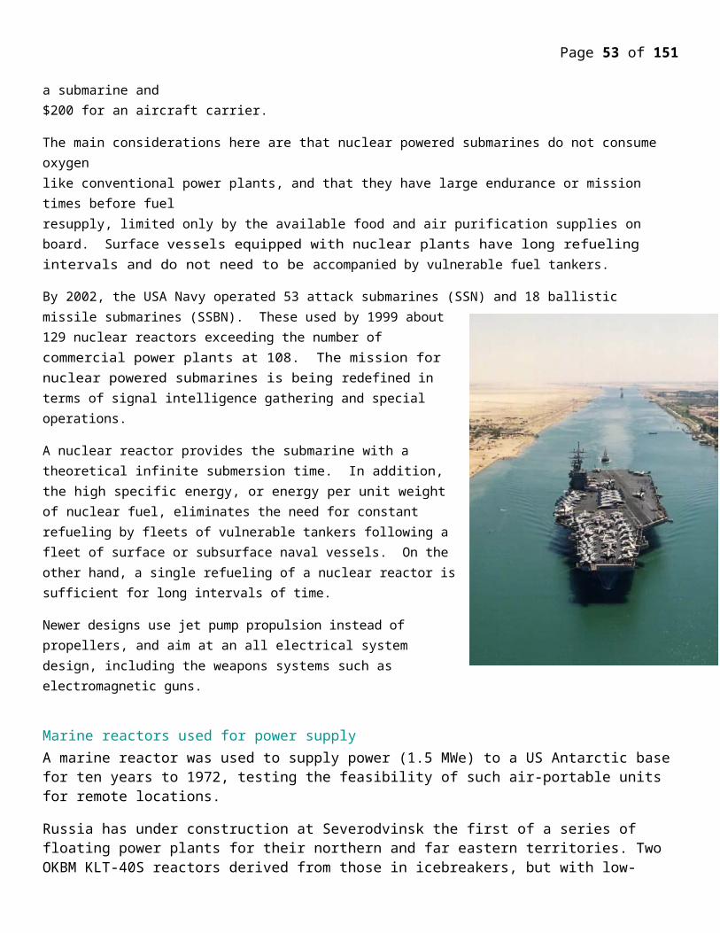
Page 53 of 107
The reactor for the Nautilus was a light water moderated, highly enriched in Uranium235 core, with zirconium clad fuel plates. The high fuel enrichment gives the reactor a compact size, and a high reactivity reserve to override the xenon poison dead time. The Nautilus beat numerous records, establishing nuclear propulsion as the ideal driving force for the world's submarine fleet. Among its feats was the first underwater crossing of the Arctic ice cap. It traveled 1,400 miles at an average speed of 20 knots. On a first core without refueling, it traveled 62,000 miles.
Zirconium has a low neutron absorption cross section and, like stainless steel, forms a protective, invisible oxide film on its surface upon exposure to air. This oxide film is composed of zirconia or ZrO2 and is on the order of only 50 to 100 angstroms in thickness. This ultra thin oxide prevents the reaction of the underlying zirconium metal with virtually any chemical reagent under ambient conditions. The only reagent that will attack zirconium metal at room temperature is hydrofluoric acid, HF, which will dissolve the thin oxide layer off of the surface
{Experimental setup for testing Nautilus type naval reactors at the Idaho National Engineering Laboratory, INEL, 1989}
Normal Naval reactor design features The nuclear propulsion plant uses a pressurized water reactor design which has two basic systems - a primary system and a secondary system. The primary system circulates ordinary water and consists of the reactor, piping loops, pumps and steam generators. The heat produced in the reactor is transferred to the water under high pressure so it does not boil. This water is pumped through the steam generators and back into the reactor for re-heating.
In the steam generators, the heat from the water in the primary system is transferred to the secondary system to create steam. The secondary system is isolated from the primary system so that the water in the two systems does not intermix.
In the secondary system, the steam flows from the steam generators to drive the turbine generators, which supply the ship with electricity, and to the main propulsion turbines, which drive the propeller. After passing through the turbines, the steam is condensed into water which is fed back to the steam generators by the feed pumps. Thus, both the primary and secondary systems are closed systems where water is recirculated and renewed.
Since there is no step in the generation of this power which requires the presence of air or oxygen, this allows the ship to operate completely independent from the earth’s atmosphere for extended periods of time.
Page 54 of 107
Naval reactors undergo repeated power changes for ship maneuvering, unlike civilian counterparts which operate at steady state. Nuclear safety, radiation, shock, quieting, and operating performance requirements in addition to operation in close proximity to the crew dictate exceptionally high standards for component manufacturing and quality assurance. The internals of a Naval reactor remain inaccessible for inspection or replacement throughout a long core life -- unlike a typical commercial nuclear reactor, which is opened for refueling roughly every eighteen months.
Unlike commercial nuclear power plants, Naval reactors must be rugged and resilient enough to withstand decades of rigorous operations at sea, subject to a ship's pitching and rolling and rapidly-changing demands for power, possibly under battle conditions. These conditions -- combined with the harsh environment within a reactor plant, which subjects components and materials to the long-term effects of irradiation, corrosion, high temperature and pressure -- necessitate an active, thorough and far-sighted technology effort to verify reactor operation and enhance the reliability of operating plants, as well as to ensure Naval nuclear propulsion technology provides the best options for future needs.
Page 55 of 107
With the demise of the commercial nuclear industry in the 1970's, Naval nuclear suppliers have had virtually no other work to help absorb overhead and sustain a solid business base from which to compete for Naval nuclear work. The result has been reduced competition and higher costs. Requirements for naval nuclear propulsion plant components are far more stringent than needed for civilian products. Costly quality control and work production procedures to meet nuclear requirements generally prevent these firms from competing successfully with firms geared for less sophisticated civilian work. There is no civilian demand for quiet, compact, shock-resistant nuclear propulsion systems which would keep skilled designers and production workers current. This is a distinct difference from the aerospace, electronics, and ground vehicle industries from which DOD buys many of its weapon systems.
The Naval Reactors' program has shown the world that nuclear power can be handled safely, with no adverse effects on the public or the environment. While others have stumbled with this challenging technology, the Naval Reactors' program stands out-in the private sector as well as in the public sector-for vision, discipline, and technical excellence.
The nuclear propulsion plants in United States Navy ships, while differing in size and component arrangements, are all rugged, compact, pressurized water reactors designed, constructed, and operated to exacting criteria. The nuclear components of these plants are all housed in a section of the ship called the reactor compartment. The reactor compartments all serve the same purpose but may have different shapes depending on the type of ship. For submarines, the reactor compartment is a horizontal cylinder formed by a section of the ship’s pressure hull, with shielded bulkheads on each end. Cruiser reactor compartments are shielded vertical cylinders or shielded rectangular boxes deep within the ship’s structure.
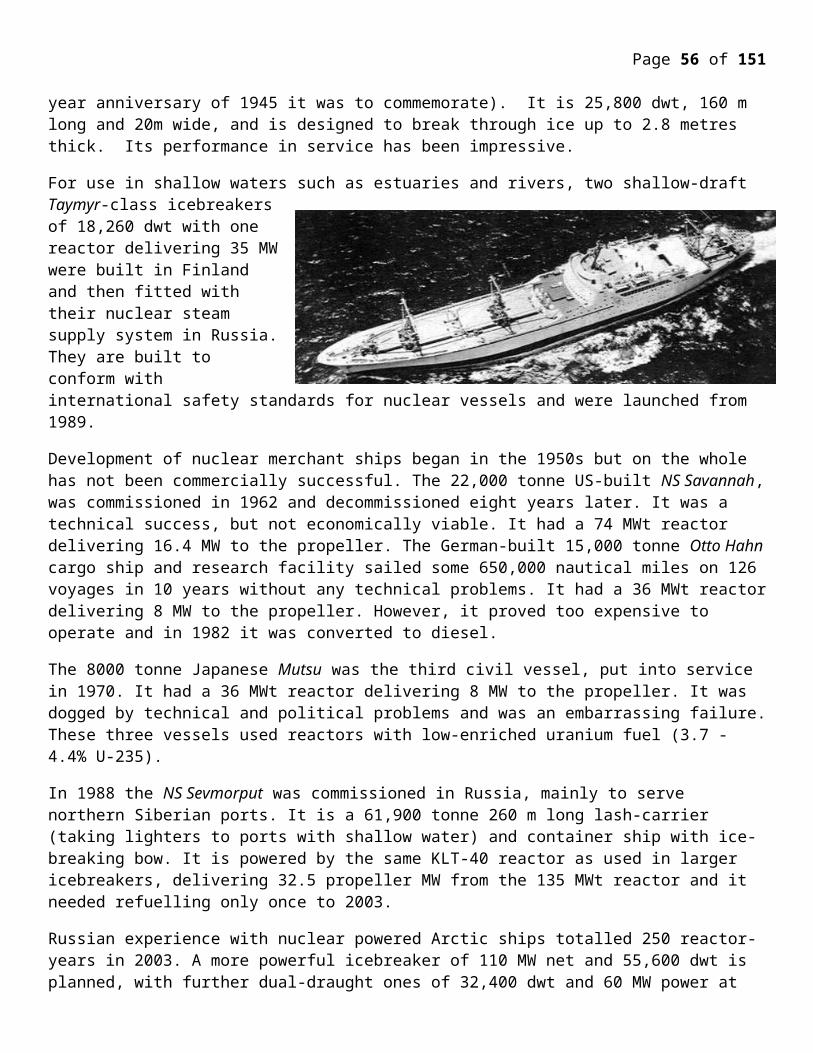
Page 56 of 107
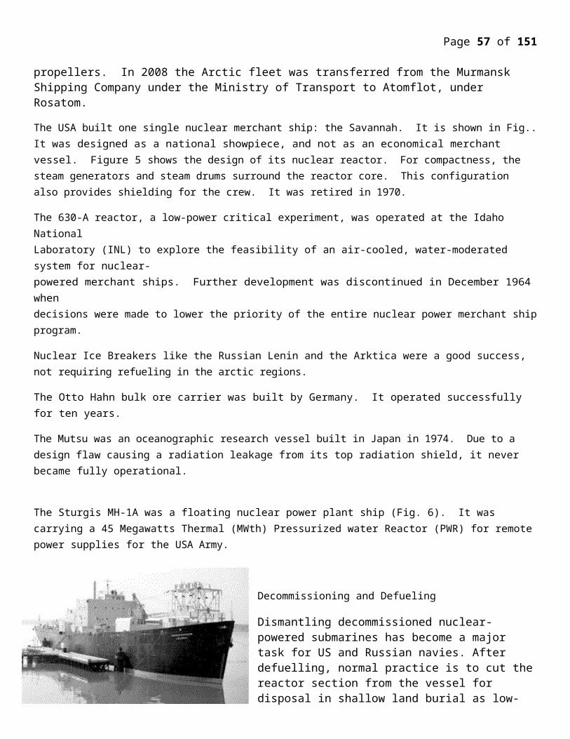
Page 57 of 107
The propulsion plants of nuclear-powered ships remain a source of radiation even after the vessels are shut down and the nuclear fuel is removed. Defueling removes all fission products since the fuel is designed, built and tested to ensure that fuel will contain the fission products. Over 99.9% of the radioactive material that remains is an integral part of the structural alloys forming the plant components. The radioactivity was created by neutron irradiation of the iron and alloying elements in the metal components during operation of the plant. The remaining 0.1% is radioactive corrosion and wears products that have been circuited by reactor coolant, having become radioactive from exposure to neutrons in the reactor core, and then deposited on piping system internals.
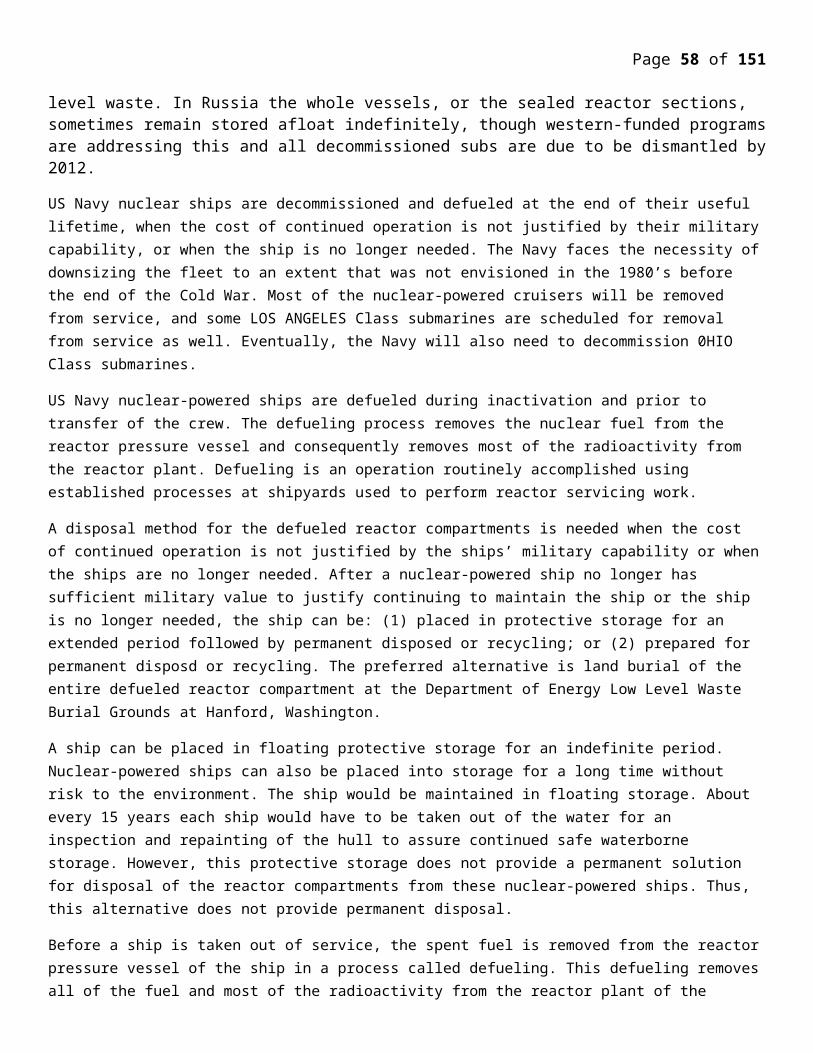
Page 58 of 107
The fuel in a reactor contains uranium atoms sealed within metal cladding. Uranium is one of the few materials capable of producing heat in a self-sustaining chain reaction. When a neutron causes a uranium atom to fission, the uranium nucleus is split into parts producing atoms of lower atomic number called fission products. When formed, the fission products initially move apart at very high speeds, but they do not travel very far, only a few thousandths of an inch, before they are stopped within the fuel cladding. Most of the heat produced in the fission process comes from stopping these fission products within the fuel and converting their kinetic energy into heat.
Radioactivity is created during fission because some of these fission products are highly radioactive when they are formed. Most of the radioactivity produced by nuclear fuel is in the fission products. The uranium fuel in naval nuclear propulsion reactor cores uses highly corrosion-resistant and highly radiation-resistant fuel and cladding. As a result, the fuel is very strong and has very high integrity. The fuel is designed, built, and tested to ensure that the fuel construction will contain and hold the radioactive fission products. Naval fuel totally contains fission products with the fuel - there is no fission product release from the fuel in normal operation.
Fissioning of uranium also produces neutrons while the nuclear power plant is operating. Most of the neutrons produced are absorbed by the atoms within the fuel and continue the chain reaction. However, some of the neutrons travel away from the fuel, go outside the fuel, and are absorbed in the metal structure which supports the fuel or in the walls of the reactor pressure vessel. Trace amounts of corrosion and wear products are carried by reactor coolant from reactor plant metal surfaces. Some of these become radioactive born exposure to neutrons.
Reactor coolant carries some of these radioactive products through the piping systems where a portion of the radioactivity is removed by a purification system. Most of the remaining radionuclides transported from the reactor core
Page 59 of 107
deposit in the piping systems. These neutrons, when absorbed in the nucleus of a nonradioactive atom like iron, can produce a radioactive atom. For example, iron-54 contains a total of 54 particles. Adding an additional neutron produces an atom containing 55 particles, called iron-55. This atom is radioactive. At some later time, it changes into a nonradioactive manganese-55 atom by releasing energy in the form of radiation. This is called radioactive decay.
Due to the need for sailors to live on the ships during operation, reactor compartments are designed to attenuate radiation levels outside of the reactor compartment to extremely low levels. The external surface radiation levels for the normal conditions of transportation of the cruisers and LOS ANGELES Class and 0HI0 Class submarines are expected to be a fraction of the 200 mrem per hour on contact tit dewed under 49CFR173.
Naval reactors (with one exception) have been pressurized water types, which differ from commercial reactors producing electricity in that:
they deliver a lot of power from a very small volume and therefore run on highly-enriched uranium (>20% U-235, originally c 97% but apparently now 93% in latest US submarines, c 20-25% in some western vessels, and up to 45% in later Russian ones*),
the fuel is not UO2 but a uranium-zirconium or uranium-aluminum alloy (c15%U with 93% enrichment, or more U with less - eg 20% - U-235) or a metal-ceramic (Kursk: U-Al zoned 20-45% enriched, clad in zircaloy, with c 200kg U-235 in each 200 MW core),
they have long core lives, so that refueling is needed only after 10 or more years, and new cores are designed to last 50 years in carriers and 30-40 years in submarines (US Virginia class: lifetime),
the design enables a compact pressure vessel while maintaining safety. The Sevmorput pressure vessel for a relatively large marine reactor is 4.6 m high and 1.8 m diameter, enclosing a core 1 m high and 1.2 m diameter.
thermal efficiency is less than in civil nuclear power plants due to the need for flexible power output, and space constraints for the steam system.
* An IAEA Tecdoc reports discharge assay of submarine used fuel reprocessed at Mayak being 17% U-235.
The long core life is enabled by the relatively high enrichment of the uranium and by incorporating a "burnable poison" such as gadolinium in the cores which is progressively depleted as fission products and actinides accumulate, leading to reduced fuel efficiency. The two effects cancel one another out.
However, it was reported in 2006 that France has dropped the enrichment level for its naval fuel to 6-7% U-235.
Long-term integrity of the compact reactor pressure vessel is maintained by providing an internal neutron shield. (This is in contrast to early Soviet civil PWR designs where embrittlement occurs due to neutron bombardment of a very narrow pressure vessel.)
The Russian Alfa-class submarines had a single liquid metal cooled reactor (LMR) of 155 MWt and using very highly enriched uranium. These were very fast, but had operational problems in ensuring that the lead-bismuth coolant did not freeze when the reactor was shut down. The design was unsuccessful and used in only eight trouble-plagued vessels.
Reactor power ranges from 10 MWt (in a prototype) up to 200 MW (thermal) in the larger submarines and 300 MWt in surface ships such as the Kirov-class battle cruisers. The French Rubis-class submarines have a 48 MW
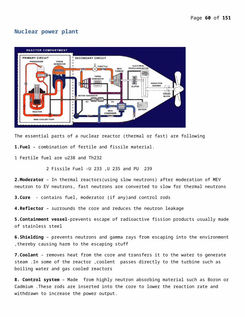
Page 60 of 107
reactor which needs no refueling for 30 years. British Vanguard class submarines of 15,400 t have a single PWR2 reactor with two turbines driving a single pump jet of 20.5 MW. New versions of this with "Core H" will require no refueling over the life of the vessel. Russia's Oscar-II class has two 190 MWt reactors.
The Russian, US and British navies rely on steam turbine propulsion, the French and Chinese use the turbine to generate electricity for propulsion.
Russian ballistic missile submarines as well as all surface ships since the Enterprise are powered by two reactors. Other submarines (except some Russian attack subs) are powered by one. A new Russian test-bed submarine is diesel-powered but has a very small nuclear reactor for auxiliary power.
The French aircraft carrier Charles de Gaulle, commissioned in 2000, has two PWR units driving 61 MW Alstom turbines and the system can provide 5 years running at 25 knots before refueling. Areva TA (formerly Technicatome) will provide six naval reactors developed from these for France's Barracuda submarines, the first to be commissioned in 2014. The last of its Le Triomphant class of nuclear submarines (14,000 DWT) was launched in 2008 with an Areva TA 150 MW PWR designated K15. These units will also power the Barracuda class.
The larger Russian Arktika class icebreakers use two OK-900A (essentially KLT-40) nuclear reactors of 171 MW each with 241 or 274 fuel assemblies of 45-75% enriched fuel and 3-4 year refueling interval. They drive steam turbines and each produce up to 33 MW (44,000 hp) at the propellers, though overall power is 54 MW. The two Tamyr class icebreakers have a single 171 MW KLT-40 reactor giving 35 MW propulsive power. Sevmorput uses one 135 MW KLT-40 unit producing 32.5 MW propulsive, and all those use 90% enriched fuel. (The now-retired Lenin's first OK-150 reactors used 5% enriched fuel but were replaced by OK-900 units with 45-75% enriched fuel.) Most of the Arktika-class vessels have had operating life extensions based on engineering knowledge built up from experience with Arktika itself. It was originally designed for 100,000 hours of reactor life, but this was extended first to 150,000 hours, then to 175,000 hours. In practice this equated to a lifespan of eight extra years of operation on top of the design period of 25. In that time, Arkitka covered more than 1 million nautical miles.
For the next generation of Russian icebreakers, integrated light water reactor designs are being investigated possibly to replace the conventional PWR. Russia is developing a new icebreaker reactor - RITM-200 - to replace the current KLT reactors. This is an integral 210 MWt, 55 MWe PWR with inherent safety features. For floating nuclear power plants (see below) a single RITM-200 would replace twin KLT-40S (but yield less power).
NAVAL REACTOR DEVELOPMENT
INTRODUCTIONThere have been more reactor concepts investigated in the naval propulsion area by different manufacturers and laboratories than in the civilian field, and much can be learned from their experience for land applications.
According to the type of vessel they power they have different first letter designations: A for Aircraft carrier, C for Cruiser, D for Destroyer or Cruiser and S for Submarine. They are also designated with a last letter according to the designer institution or lead laboratory: B for Bechtel, C for Combustion Engineering, G for General Electric and W for Westinghouse.
A middle number between the first and last letter refers to the generation number of the core design. For instance, the A1B is the first generation of a core design for aircraft carriers with Bechtel operating the lead laboratory for the design.
Page 61 of 107
Naval reactors designs use boron as a burnable neutron poison. The fuel is an alloy of 15 percent zirconium and 85 percent uranium enriched to a level of 93 percent in U235. The burnable poisons and high enrichment allow a long core lifetime and provides enough reactivity to overcome the xenon poisoning reactor dead time. The vertical direction doping provides a long core life, and the radial doping provides for an even power and fuel burn-up distribution.
STR OR S1W PRESSURIZED WATER REACTOR DESIGN The Westinghouse Electric Corporation under contract to the USA Navy constructed, tested and operated a prototype pressurized water reactor submarine reactor plant. This first reactor plant was called the Submarine Thermal Reactor, or STR. On March 30, 1953, the STR was brought to power for the first time and the age of naval nuclear propulsion was born. In 1953 it achieved a 96 hours sustained full power run simulating a crossing of the Atlantic Ocean. The second S1W core sustained in 1955 a 66 days continuous full power simulating a high speed run twice around the globe.
The STR was redesigned as the first generation submarine reactor S1W, which became critical on March 30, 1953, was the prototype of the USS Nautilus (SSN 571) reactor and was followed in the middle to late 1950s by the Aircraft carrier A1W, the prototype of the aircraft carrier USS Enterprise plant.
Westinghouse's Bettis Atomic Power Laboratory was assigned the responsibility for operating the reactor it had designed and built, hence the W in the name. The crew was increasingly augmented by naval personnel as the cadre of trained operators grew
The fuel elements are sandwich plates made of U and Zr and clad in Zr. The maximum temperature in the fuel was 645 oF and the sheath temperature was 551 oF with an average cycle time of 600 hours or just 600 / 24 = 25 days. The reactor temperature is limited by the pressure needed to prevent boiling, necessitating high pressure vessels, piping and heat exchangers. The steam was generated at a relatively low pressure. A high level of pumping power was required, and the fuel was costly. However this design had few hazards, has been proven in service, and an expensive moderator was not needed.
The S1C reactor used an electric drive rather than a steam turbine like in the subsequent S5W reactor design rated at 78 MWth and a 93 percent U235 enriched core that was the standard in the 1970s. The S6G reactor plant was rated at 148 MWth and the D2W core was rated at 165 MWth.
The S6G reactor is reported to be capable of propelling a Los Angeles class submarine at 15 knots or 27.7 km/hr when surfaced and 25 knots or 46.3 km/hr while submerged. The Sea wolf class of submarines was equipped with a single S6W reactor, whereas the Virginia class of submarines is expected to be equipped with an S9G reactor.
The higher achievable submerged speed is due to the absence of wave friction underwater suggesting that submarine cargo ships would offer a future energy saving alternative to surface cargo ships.
LARGE SHIP REACTORS, A1W-A, A1W-B PROTOTYPE PLANTS The A1W (aircraft carrier, first prototype, Westinghouse) plant consisted of a pair of prototype reactors for the USS Enterprise USA Navy nuclear-powered aircraft carrier. Located at the Naval Reactors Facility, the two pressurized-water reactors (designated A and B) were built within a portion of a steel hull. The plant simulated the Enterprise’s engine room. All components could withstand seagoing use.
Page 62 of 107
The A1W plant was the first in which two reactors powered one ship propeller shaft through a single-geared turbine propulsion unit. As the Navy program evolved, new reactor cores and equipment replaced many of the original components. The Navy trained naval personnel at the A1Wplant and continued a test program to improve and further develop operating flexibility.
The A1W prototype plant was started in 1956 for surface ships using two pressurized water reactors. The plant was built as a prototype for the aircraft carrier USS Enterprise (CVN 65), which was the first nuclear-powered aircraft carrier. Power operation of the A1W plant started in October of 1958.
In the A1W and A2W designs, the coolant was kept at a temperature between 525-545 °F or 274-285 °C. In the steam generators, the water from the feed system is converted to steam at 535 °F or 279 °C and a pressure of about 600 psi or 4 MPa . The reactor coolant water was recalculated by four large electric pumps for each reactor.
The steam was channeled from each steam generator to a common header, where the steam is then sent to the main engine, electrical generators, aircraft catapult system, and various auxiliaries. The main propulsion turbines are double ended, in which the steam enters at the center and divides into two opposing streams.
The main shaft was coupled to a reduction gear in which the high rotational velocity of the turbine shaft is stepped down to a usable turn rate for propelling the ship. In the A3W reactor design used on the USS John F. Kennedy a 4 reactor design is used. In the A4W design with a life span of 23 years on the Nimitz class carriers only two reactors per ship are used with each providing 104 MWth of power or 140,000 shaft HP. The A1B is also a two reactor design for the Gerald R. Ford class of carriers.
SIR OR S1G INTERMEDIATE FLUX BERYLLIUM SODIUM COOLED REACTORThis reactor design was built by the General Electric (GE) Company, hence the G designation. The neutron spectrum was intermediate in energy. It used UO2 fuel clad in stainless steel with Be used as a moderator and a reflector. The maximum temperature in the fuel could reach 1,700 +/- 300 oF with a maximum sheath temperature of 900 oF, with a cycle time of 900 hours or 900 / 24 = 37.5 days.
A disadvantage is that the coolant becomes activated with the heat exchangers requiring heavy shielding. In addition Na reacts explosively with water and the fuel element removal is problematic. On the other hand high reactor and steam temperatures can be reached with a higher thermal efficiency. A low pressure is used in the primary system.
Beryllium has been used as a moderator in the Sea Wolf class of submarines reactors. It is a relatively good solid moderator, both from the perspectives of slowing down power and of the moderating ratio, and has a very high thermal conductivity. Pure Be has good corrosion resistance to water up to 500 oF, to sodium to 1,000 oF, and to air attack to 1,100 oF. It has a noted vapor pressure at 1,400 oF and is not considered for use much above 1,200 oF even with an inert gas system. It is expensive to produce and fabricate, has poor ductility and is extremely toxic necessitating measures to prevent inhalation and ingestion of its dust during fabrication.
A considerably small size thermal reactor can be built using beryllium oxide as a moderator. It has the same toxicity as Be, but is less expensive to fabricate. It can be used with a sodium cooled thermal reactor design because BeO is corrosion resistant to sodium. It has similar nuclear properties to Be, has a very high thermal conductivity as a ceramic, and has a good resistance to thermal shock. It can be used in the presence of air, sodium and CO2. It is volatile in water vapor above 1,800 oF. In its dense form, it resists attack by Na or Na-K at a temperature of 1,000 oF. BeO can be used as a fuel element material when impregnated with uranium. Low density increases its resistance to shock. A BeO coating can be applied to cut down on fission products release to the system.
Page 63 of 107
The USS Seawolf submarine, initially used a Na cooled reactor that was replaced in 1959 by a PWR to standardize the fleet, because of superheated bypass problems causing mediocre performance and as a result of a sodium fire. The steam turbines had their blades replaced to use saturated rather than superheated steam. The reactor was housed in a containment vessel designed to contain a sodium fire. The eighth generation S8G reactor was capable of operating at a significant fraction of full power without reactor coolant pumps. The S8G reactor was designed by General Electric for use on the Ohio class (SSGN/SSBN-726) submarines. A land based prototype of the reactor plant was built at Knolls Atomic Power Laboratory at Ballston Spa, New York. The prototype was used for testing and crew training throughout the 1980s. In 1994, the core was replaced with a sixth generation S6W Westinghouse reactor, designed for the Sea Wolf class submarines.
EXPERIMENTAL BERYLLIUM OXIDE REACTOR, EBOR The Experimental Beryllium Oxide Reactor’s objective was to develop beryllium oxide as a neutron moderator in high-temperature, gas-cooled reactors. The project was canceled in 1966 before construction was complete.
Among the reasons for the cancellation was the encouraging progress achieved, concurrent with EBOR construction, in developing graphite as a moderator. This reduced the importance of developing beryllium oxide as an alternate.
No uranium fuel ever was loaded into the Experimental Beryllium Oxide reactor and it never operated or went critical before the program was canceled. It was “a reactor,” but never an operating one.
SC-WR SUPER CRITICAL WATER REACTOR The Super Critical Water Reactor (SC-WR) was considered with an intermediate energy neutron spectrum. The fuel was composed of UO2 dispersed in a stainless steel matrix. It consisted of 1 inch square box with parallel plates and sine wave filters with a type 347 stainless steel cladding 0.007 inch thick. The maximum temperature in the fuel reached 1,300 oF with an average cycle time of 144 hours or 144 / 24 = 6 days.The materials for high pressure and temperature and the retention of mechanical seals and other components were a service problem. The water coolant reached a pressure of 5,000 psi. The high pressure and temperature steam results in a high cycle efficiency, small size of the reactor with no phase change in the coolant.
ORGANIC MODERATED REACTOR EXPERIMENT, MOREThe Organic Cooled and Moderated Reactor has been considered as a thermal neutron spectrum shipboard power plant.
The waxy coolant was considered promising because it liquified at high temperatures but didn’t corrode metal like water did.
Also, it operated at low pressures, significantly reducing the risk of leaking. A scaled-up reactor, the Experimental Organic Cooled Reactor, was built next door in anticipation of further development of the concept.
The rectangular-plates fuel clad in aluminum can be natural uranium since the Terphenyl organic coolant can have good moderating properties. The cladding temperature can reach 800 oF with an average cycle time of 2,160 hours or 2,160 / 24 = 90 days.
The overall heat transfer coefficient of the coolant is low with the formation of polymers under irradiation that require a purification system. The advantages are negligible corrosion and the achievement of low pressure at a high temperature.
Page 64 of 107
A diphenyl potential coolant broke down under irradiation. The hydrogen in the compound turned into a gas forming bubbles. The bubbles reduced the moderator density and made it difficult to maintain the chain reaction. The initially clear liquid turned into a gummy and black breakup product.
No uranium fuel ever was loaded into the reactor and it never operated or went critical before the program was canceled. It was “a reactor,” but never “an operating reactor.”
LEAD-BISMUTH COOLED FAST REACTORS The alpha class of Russian submarines used an alloy of Pb-Bi 45-50 percent by weight cooled fast reactors. The melting point of this alloy is 257 oF. They faced problems of corrosion of the reactor components, melting point, pump power, polonium activity and problems in fuel unloading.
Refueling needed a steam supply to keep the liquid metal molten. Bismuth leads to radiation from the activated products, particularly polonium. An advantage is that at decommissioning time, the core can be allowed to cool into a solid mass with the lead providing adequate radiation shielding.
This class of submarines has been decommissioned.
NATURAL CIRCULATION S5G PROTOTYPEThe S5G was the prototype of a pressurized-water reactor for USS Narwhal. Located at the Naval Reactors Facility, it was capable of operating in either a forced or natural circulation flow mode. In the natural circulation mode, cooling water flowed through the reactor by thermal circulation, not by pumps. Use of natural circulation instead of pumps reduced the noise level in the submarine.
To prove that the design concept would work in an operating ship at sea, the prototype was built in a submarine hull section capable of simulating the rolling motion of a ship at sea. The S5G continued to operate as part of the Navy’s nuclear training program until that program was reduced after the end of the Cold War.
The S5G reactor had two coolant loops and two steam generators. It had to be designed with the reactor vessel situated low in the boat and the steam generators high in order for natural circulation of the coolant to be developed and maintained.
This nuclear reactor was installed both as a land-based prototype at the Nuclear Power Training Unit, Idaho National Engineering Laboratory near Idaho Falls, Idaho, and on board the USS Narwhal (SSN-671), now decommissioned.
The prototype plant in Idaho was given a rigorous performance check to determine if such a design would work for the USA Navy. It was largely a success, although the design never became the basis for any more fast attack submarines besides the Narwhal. The prototype testing included the simulation of essentially the entire engine room of an attack submarine. By floating the plant in a large pool of water, the whole prototype could be rotated along its long axis to simulate a hard turn. This was necessary to determine whether natural circulation would continue even during hard maneuvers, since natural circulation is dependent on gravity.
The USS Narwhal had the quietest reactor plant in the USA naval fleet. Its 90 MWth reactor plant was slightly more powerful than the other fast attack USA nuclear submarines of that era such as the third generation S3G and the fifth generation S5W. The Narwhal contributed significantly to the USA effort during the Cold War. With its quiet propulsion
Page 65 of 107
and the pod attached to its hull, it used a towed sonar array and possibly carried a Remotely Operated Vehicle (ROV) for tapping into communication cables and maintaining a megaphones tracking system at the bottom of the oceans.
It was intended to test the potential contribution of natural circulation technology to submarine noise suppression by the avoidance of forced flow pump cooling. The reactor primary coolant pumps are one of the primary sources of noise from submarines in addition to the speed reduction gearbox and cavitation from the propeller. The elimination of the coolant pumps and associated equipment would also reduce mechanical complexity and the space required by the propulsion equipment.
The S5G was the direct precursor to the eighth generation S8G reactor used on the Ohio class ballistic missile submarines; a quiet submarine design.
The S5G was also equipped with coolant pumps that were only needed in emergencies to attain high power and speed. The reactor core was designed with very smooth paths for the coolant. Accordingly, the coolant pumps were smaller and quieter than the ones used by the competing S5W core, a Westinghouse design. They were also fewer in numbers. In most situations, the submarine could be operated without using the coolant pumps, useful for stealth operation. The reduction in electrical requirements enabled this design to use only a single electrical turbine generator plant.
The S8G prototype used natural circulation allowing operation at a significant fraction of full power without using the reactor pumps, providing a silent stealth operation mode. To further reduce engine plant noise, the normal propulsion setup of two steam turbines driving the propeller screw through a reduction gear unit was changed instead to one large propulsion turbine without reduction gears. This eliminated the noise from the main reduction gears, but at the expense of a large main propulsion turbine. The turbine was cylindrical, about 12 feet in diameter and 30 feet in length. This large size was necessary to allow it to turn slowly enough to directly drive the screw and be fairly efficient in doing so. The same propulsion setup was used on both the USS Narwhal and its land based prototype
FAIL SAFE CONTROL AND LOAD FOLLOWING S7G DESIGN
The S7G core was controlled by stationary gadolinium clad tubes that were partially filled with water. Water was pumped from the portion of the tube inside the core to a reservoir above the core, or allowed to flow back down into the tube. A higher water level in the tube within the core slowed down the neutrons allowing them to be captured by the gadolinium tube cladding rather than the uranium fuel, leading to a lower power level.
The system had a failsafe control system. The pump needed to run continually to keep the water level pumped down. Upon an accidental loss of power, all the water would flow back into the tube, shutting down the reactor.
This design also had the advantage of a negative reactivity feedback and a load following mechanism. An increase in reactor power caused the water to expand to a lower density lowering the power. The water level in the tubes controlled average coolant temperature, not reactor power. An increase in steam demand resulting from opening the main engines throttle valves would automatically increase reactor power without action by the operator.
S9G HIGH ENERGY DENSITY CORE
Page 66 of 107
The S9G is a PWR built by General Electric with increased energy density, and new plant components, including a new steam generator design featuring improved corrosion resistance and a reduced life cycle cost. This reactor in the Virginia class SSN-774 submarines is designed to operate for 33 years without refueling and last the expected 30 year design life of a typical submarine.
The higher power density decreases not only size but also enhances quiet operation through the elimination of bulky control and pumping equipment. It would be superior to any Russian design from the perspective of noise reduction capability, with 30 units planned to be built.
Table 1. Power ratings of naval reactor designs.
Reactor type Rated power
shaft horse power[shp], [MW]
A2W 35,000 26.1
A4W/A1G 140,000 104.4
C1W 40,000 29.8
D2G 35,000 26.1
S5W 15,000 11.2
S5G 17,000 12.7
S6W 35,000 26.1
S8G 35,000 26.1
S9G 40,000 29.8
EXPENDED CORE FACILITY, ECF The Expended Core Facility was built in 1957. It was used to examine expended naval reactor fuel to aid in the improvement of future generations of naval reactors. In the middle 1960s, the fifth generation S5G, the prototype of the submarine USS Narwhal reactor, and predecessor to the reactor plant used to propel the Trident Fleet Ballistic Missile Submarines, was built and placed in service by the General Electric Company.
The Expended Core Facility ECF was built to examine and test fuel from nuclear powered vessels, prototype plants, and the Shipping port Power Plant. It has examined specimens of irradiated fuel that were placed in a test reactor, such as the Advanced Test Reactor (ATR).
The information from detailed study of this fuel has enabled the endurance of naval nuclear propulsion plants to be increased from two years for the first core in Nautilus to the entire 30+ year lifetime of the submarines under construction today. It originally consisted of a water pool and a shielded cell with a connecting transfer canal. It has been modified by the addition of three more water pools and several shielded cells. The water pools permit visual observation of naval spent nuclear fuel during handling and inspection
Page 67 of 107
while shielding workers from radiation. The shielded cells are used for operations which must be performed dry.
NAVAL REACTORS RESEARCH AND DEVELOPMENTThe USA Navy's research and development expanded in eastern Idaho, and by late 1954, the Nuclear Power Training Unit was established. In 1961, the Naval Administrative Unit set up shop in Blackfoot. In 1965, the unit moved to a location at Idaho Falls
In the early 1950s work was initiated at the Idaho National Engineering and Environmental Laboratory (INEEL) to develop reactor prototypes for the USA Navy. The Naval Reactors Facility, a part of the Bettis Atomic Power Laboratory, was established to support development of naval nuclear propulsion. The facility was operated by the Westinghouse Electric Corporation under the direct supervision of the DOE's Office of Naval Reactors. The facility supports the Naval Nuclear Propulsion Program by carrying out assigned testing, examination, and spent fuel management activities.
The facility consisted of three naval nuclear reactor prototype plants, the Expended Core Facility, and various support buildings. The Submarine Thermal Reactor (STR) prototype was constructed in 1951 and shut down in 1989; the large ship reactor prototype was constructed in 1958 and shut down in 1994; and the submarine reactor plant prototype was constructed in 1965 and shut down in 1995.
The prototypes were used to train sailors for the nuclear navy and for research and development purposes. The Expended Core Facility, which receives, inspects, and conducts research on naval nuclear fuel, was constructed in 1958.
The initial power run of the prototype reactor (S1W) as a replacement of the STR for the first nuclear submarine, the Nautilus, was conducted at the INEEL Laboratory in 1953. The A1W prototype facility consisted of a dual-pressurized water reactor plant within a portion of the steel hull designed to replicate the aircraft carrier Enterprise. This facility began operations in 1958 and was the first designed to have two reactors providing power to the propeller shaft of one ship. The S5G reactor was a prototype pressurized water reactor that operated in either a forced or natural circulation flow mode. Coolant flow through the reactor was caused by natural convection rather than pumps. The S5G prototype plant was installed in an actual submarine hull section capable of simulating the rolling motions of a ship at sea.
The Test Reactor Area (TRA) occupied 102 acres in the southwest portion of the INEEL laboratory. The TRA was established in the early 1950s with the development of the Materials Test Reactor (MTR). Two other major reactors were subsequently built at the TRA: the Engineering Test Reactor (ETR) and the Advanced Test Reactor (ATR). The Engineering Test Reactor has been inactive since January 1982. The Materials Test Reactor was shut down in 1970.
The major program at the TRA became the Advanced Test Reactor. Since the Advanced Test Reactor achieved criticality in 1967, it was used almost exclusively by the Department of Energy's Naval Reactors Program. After almost 30 years of operation, it is projected to remain a major facility for research, radiation testing, and isotope production into the next century.
The Navy makes shipments of naval spent fuel to INEEL that are necessary to meet national security requirements to defuel or refuel nuclear powered submarines, surface warships, or naval prototype or training reactors, or to ensure examination of naval spent fuel from these sources. The total number of shipments of naval spent fuel to INEEL through 2035 would not exceed 575 shipments or 55 metric tonnes of spent fuel.
Page 68 of 107
CIVILIAN REACTOR DESIGNSThe nuclear navy benefited the civilian nuclear power program in several ways. It first demonstrated the feasibility of the Pressurized Water Reactor (PWR) concept, which is being currently used in the majority of land based power reactors. Second, naval reactors accumulated a large number of operational experience hours, leading to improvements in the land based reactors. The highly trained naval operational crews also become of great value to the civilian nuclear utilities providing them with experienced staffs in the operation and management of the land based systems.
Land based reactors differ in many way from naval reactors. The power of land based reactors is in the range of 3,000 MWth or higher. In contrast, a submarine reactor's power is smaller in the range of the hundreds of MWths. Land based systems use uranium fuel enriched to the 3-5 percent range. Highly enriched fuel at the 93-97 percent level is used in naval reactors to provide enough reactivity to override the xenon poison dead time, compactness as well as provide higher fuel burnup and the possibility for a single fuel loading over the useful service time of the powered ship.
[Loop type of naval reactor design for the nuclear ship Savannah. The reactor core is surrounded by the heat exchangers and the steam drums. The horizontal steam generator was replaced by a vertical tube steam generator and an integrated system in future designs]
Table 2 shows the composition of highly enriched fuel used in nuclear propulsion as well as space reactor designs such as the SAFE-400 and the HOMER-15 designs. Most of the activity is caused by the presence of U234, which ends up being separated with the U235 component during the enrichment process. This activity is primarily alpha decay and does not account for any appreciable dose. Since the fuel is highly purified and there is no material such as fluorine or oxygen causing any (α, n) reactions in the fuel, the alpha decay of U234 does not cause a neutron or gamma ray dose. If uranium nitride (UN) is used as fuel, the interaction threshold energy of nitrogen is well above the alpha emission energies of U234. Most of the dose prior to operation from the fuel is caused by U235 decay gammas and the spontaneous fission of U238. The total exposure rate is 19.9 [µRöntgen / hr] of which the gamma dose rate contribution is 15.8 and the neutron dose rate is 4.1.
Table 2. Composition of highly enriched fuel for naval and space reactors designs
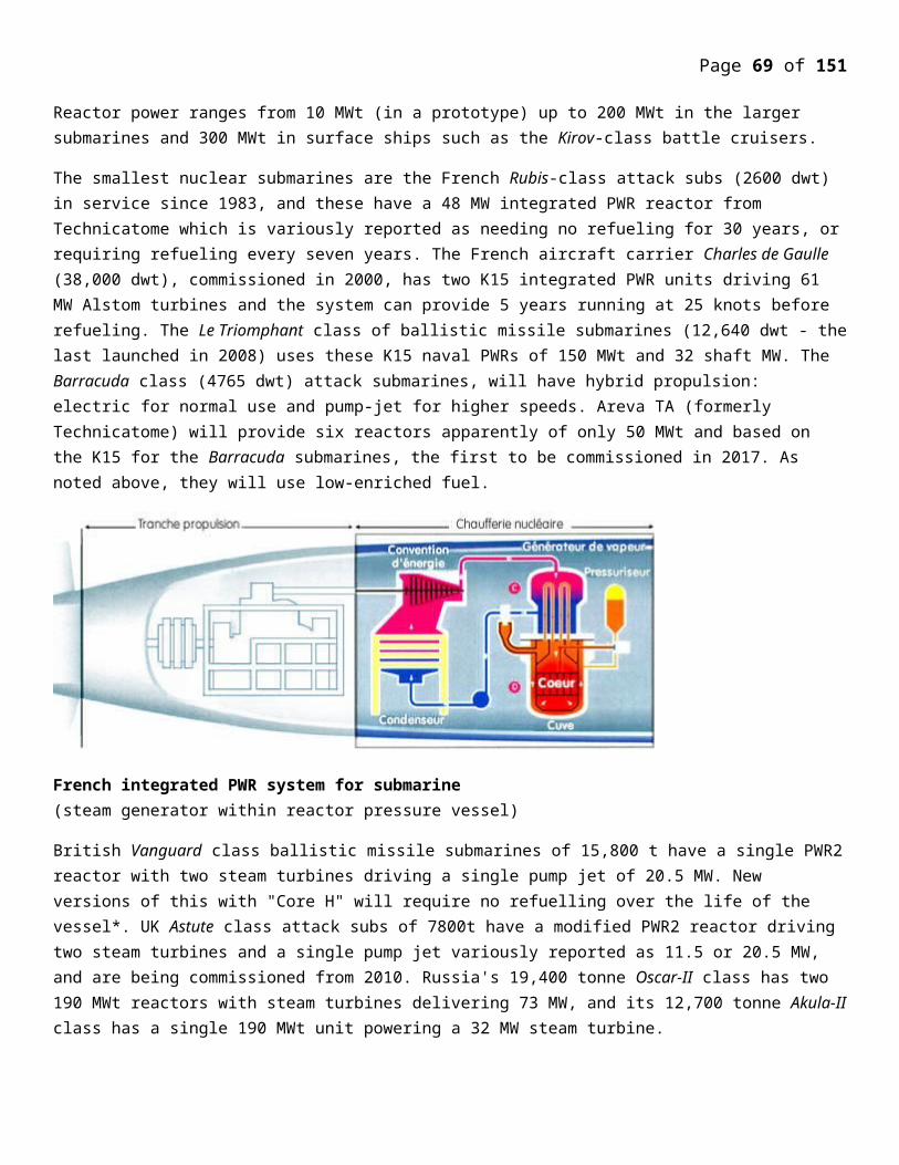
Page 69 of 107
Isotope Composition Activity Decay Exposure
(percent) [µR/hr](Curies) Mode Contribution
U234 0.74 6.1 Alpha decay unappreciable
U235 97.00 Decay gammas appreciable
U238 2.259 Spontaneous appreciable fissions
Pu239 0.001 Alpha decay unappreciable
Total 6.5 19.9
Reactor operators can wait for a 24 hours period; the reactor dead time, on a land based system for the xenon fission product to decay to a level where they can restart the reactor. A submarine cannot afford to stay dead in the water for a 24 hour period if the reactor is shutdown, necessitating highly enriched fuel. A nuclear submarine has the benefit of the ocean as a heat sink, whereas a land based reactor needs large amounts of water to be available for its safety cooling circuits
For these reasons, even though the same principle of operation is used for naval and land based reactor designs, the actual designs differ substantially. Earlier naval reactors used the loop type circuit for the reactor design as shown in Fig. 5 for the Savannah reactor. There exists a multitude of naval reactor designs. More modern designs use the Integral circuit type shown in Fig. 7.
Because of the weight of the power plant and shielding, the reactor and associated steam generation equipment is located at the center of the ship. Watertight bulkheads isolating the reactor components surround it. The greater part of the system is housed in a steel containment, preventing any leakage of steam to the atmosphere in case of an accident. The containment vessel for the Savannah design consisted of a horizontal cylindrical section of 10.7 meters diameter, and two hemispherical covers. The height of the containment was 15.2 meters. The control rod drives are situated in a cupola of 4.27 m in diameter, on top of the containment. The containment vessel can withstand a pressure of 13 atm. This is the pressure attained in the maximum credible accident, which is postulated as the rupture of the primary loop and the subsequent flashing into steam of the entire coolant volume.
The secondary shielding consists of concrete, lead, and polyethylene and is positioned at the top of the containment. A pre-stressed concrete wall with a thickness of 122 cm surrounds the lower section of the containment. This wall rests on a steel cushion. The upper section of the secondary shielding is 15.2 cm of lead to absorb gamma radiation, and 15.2 cm of polyethylene to slow down any neutrons. The space between the lead plates is filled with lead wool. The lead used in the shielding is cast by a special method preventing the formation of voids and in homogeneities.
Page 70 of 107
The polyethylene sheets are spaced so as to allow thermal expansion. Thick collision mats consisting of alternate layers of steel and wood are placed on the sides of the containment. The effective dose rate at the surface of the secondary sheet does not exceed 5 rem/year.
The containment is airtight. Personnel can remain in it for up to 30 minutes after reactor shutdown and the radiation level would have fallen to less than 0.2 rem/hr. The primary shielding is here made of an annular water tank that surrounds the reactor and a layer of lead attached to the outer surface of the tank, to minimize space. The height of the
tank is 5.2 m, the thickness of the water layer, 84 cm, and the thickness of the lead is 5-10 cm. The weight of the primary shields is 68.2 tons, and with the water it is 118.2 tons. The weight of the containment is 227 tons. The secondary shielding weights 1795 tons consisting of: 561 tons of ordinary concrete, 289 tons of lead, 69 tons of polyethylene, and 160 tons of collison mats. The latter consist of 22 tons of wood and 138 tons of steel.
The shielding complex is optimized to minimize the space used, while providing low radiation doses to the crew quarters. It is comparatively heavy because of the use of lead and steel, and is complicated to install.
Figure above shows a naval reactor of the Integral circuit type. In this case, the design offers a substantial degree of inherent safety since the pumps; the steam generators and reactor core are all contained within the same pressure vessel. Since the primary circulating fluid is contained within the vessel, any leaking fluid would be contained within the vessel in case of an accident. This also eliminates the need for extensive piping to circulate the coolant from the core to the steam generators. In loop type circuits, a possibility exists for pipe rupture or leakage of the primary coolant pipes. This source of accidents is eliminated in an integral type of a reactor
POWER OF ELECTRON AND NEUCLEAR DECAY PROCESS (alpha,beta,gama)Mean lifetime (lifetime) their significance
This is defined as the average time that nucleus is likely to remain before it starts decaying. The mean life time in seconds is t = 1/lambda
Half life time to 0.5= 0.693/lambda =0.693xt
t =1/Lambda
Typical examples of half-lives are given below
88Ra226------1600 yr -----------88 Rn 222 = +4 2l of 4.8Mev energy (Natural radio activity)
53I131 ------6days-------- 54xe131 +B (these are called poison in nuclear reactor)
Integral type of naval reactor vessel

Page 71 of 107
n-----------10 min----------p +e +ν (Decay of free neutron into proton, electron and electron neutrino)
some other decay times (life –lives) are
Th232 ------1.4 x 10¹⁰years
U 238----------4.5 X 10⁹ years Because of very long life times, radioactive materials pose grave danger. Only because of the long life of cobalt 60 (CO60) is used since it has therapeutic value in cancer treatment is used.
NUCLEAR DECAY PROCESS (Alpha ,Beta, Gamma)In Nuclear decay process; Alpha – 4 He 2 , Beta +/- (positron + or electron - ) particles are emitted from unstable nuclei and become other stable nuclei,
Gamma – Gamma rays are emitted when a nuclei in an exited state reaches the ground state. These rays are having shorter wave length than visible light and X rays. All these reactions are radioactive.
Emission of alpha or beta particle is frequently but not always followed by emission of high energy proton radiation gamma rays.
Nuclear Data and Units – Some important and useful data for nuclear power productions are given here.
Table 1
Mass Equivalent u Energy Equivivalent Mev
Electron 5.485803X10(-4) 0.5110003
Proton 1.00727647 938.28
Neutron 1.00866501 939.573
Deutron 2.01355321 1875.628
Alpha 4.00150618 3727.409
+/- Pion 0.14983 139.5669
0 Pion 0.1449 134.9745
Meson 0.1134292 105.6595
Constants and conversion factors
1 ev =1.602189x10⁻¹⁹ j slow energy
1 Mev= 1.602189 x 10⁻¹³ j Fast energy
1 e = 1.602189 x 10⁻¹⁹ c coulomb charge
1 µ =1.660566 x 10⁻²⁷ kg = 931.502 MeV/c 2 C= velocity of light
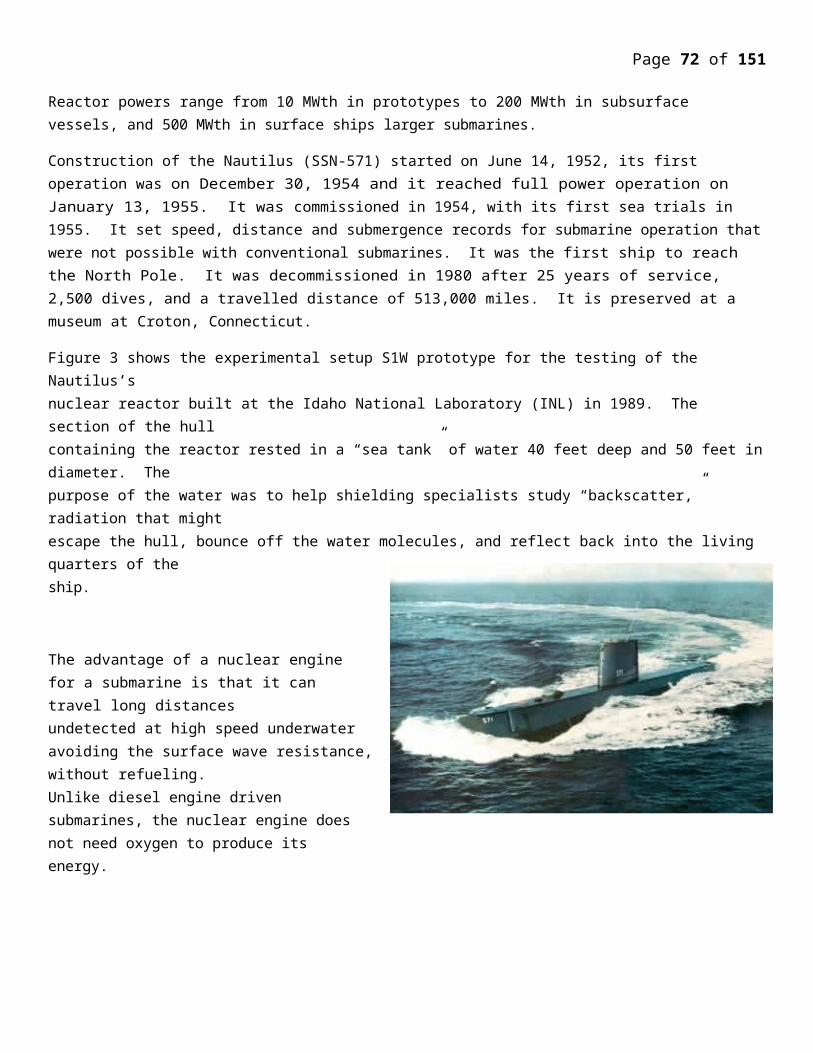
Page 72 of 107
The basic physics of conversion or breeding sequence of fertile isotopes into fissile isotope is as follows :
Uranium Chain
The required cycle is 238U -> 239 Pu ,which takes 2.75 days as follows:
238U92 -239U92->239Np93----239Pu94-----240Pu94-----241Pu94----242Pu94---241Am95
Thorium Chain:
The required cycle is 232Th -> 233U, which takes 27.4 days as follows, and is slower process than the uranium –plutonium chain by being 10 times longer: 232Th90--233Th90-233Pa91-233U92-234Pu92-235U92--236u92
XENON FORMATIONThe fission process generates a multitude of fission products with different yields. Table
3 shows some of these fission products yields resulting from the fission of three fissile isotopes:
Table 3. Fission products yield from thermal 2200 m/sec neutrons, γi [nuclei/fission event].
Isotope 92 U233 92U235 94Pu239
53I135 0.04750 0.06390 0.06040
54Xe135 0.01070 0.00237 0.01050
61Pm149 0.00795 0.01071 0.01210
The most prominent of these fission products from the perspective of reactor control is 54Xe135. It is formed as the result of the decay of 53I135. It is also formed in fission and by the decay of the Tellurium isotope: 52Te135. This can be visualized as follows:
Fission - 52Te135 + 53I135 + 54Xe135
52Te135 53I135 + -1e0 + 0ν*
53I135 54Xe135 + -1e0 + 0ν*
54Xe135 55Cs135 +-1e0 + 0ν*
55Cs13556Ba135 +-1e0 + 0ν*
The half lives of the components of this chain are shown in Table 4. The end of the chain is the stable isotope 56Ba135. Because 52Te135 decays rapidly with a half life of 11 seconds into 53I135, one can assume that all 53I135 is produced directly in the fission process. Denoting I(t) as the atomic density of iodine in [nuclei/cm3], one can write a rate equation for the iodine as:
dI(t)/dt = [rate of formation of Iodine from fission]- [rate of radioactive
transformations of Iodine] =
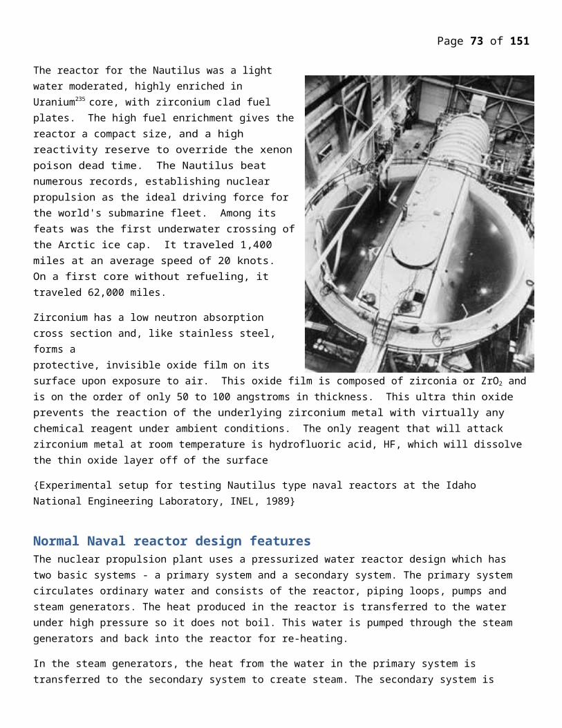
Page 73 of 107
γI is the fission yield in [nuclei/fission event],
ψ is the thermal fission cross section in [cm-1],
λI is the decay constant in [sec-1], with
Half lives of isotopes in the xenon chain.
A rate equation can also be written for the xenon in the form:
Where σaX is the thermal microscopic absorption cross section for Xenon equal to 2.65 x 10⁶. The large value of the absorption cross section of Xe, and its delayed generation from Iodine, affect the operation of reactors both under equilibrium and after shutdown conditions.
IODINE AND XENON EQUILIBRIUM CONCENTRATIONS
Under the condition of equilibrium the rate change of the xenon and Iodine concentration is zero:
This leads to an equilibrium concentration for the Iodine as:
The equilibrium concentration for the Xenon will be:
Substituting for the equilibrium concentration of the iodine, we can write:
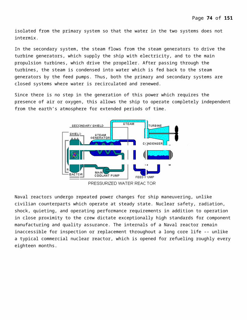
Page 74 of 107
REACTIVITY EQUIVALENT OF XENON POISONING
Ignoring the effects of neutron leakage, since it has a minor effect on fission product poisoning, we can use the infinite medium multiplication factors for a poisoned reactor in the form of the four factor formula:
and for an unpoisoned core as:
We define the reactivity ρ of the poisoned core as:
In this equation:-
is the regeneration factor,
ε is the fast fission factor, p is the resonance escape probability, ν is the average neutron yield per fission event,Σf is the macroscopic fission cross section, ΣaF is the macroscopic absorption cross section of the fuel, f is the fuel
utilization factor.
The fuel utilization factor for the unpoisoned core is given by:
and for the unpoisioned core is given by:
where:ΣaM is the moderator's macroscopic absorption coefficient, ΣaP is the poison's macroscopic absorption coefficients.
From the definition of the reactivity in Eqn. 10, and Eqns. 11 and 12 we can readily get:
It is convenient to express the reactivity in an alternate form. For the unpoisoned critical core:
From which:
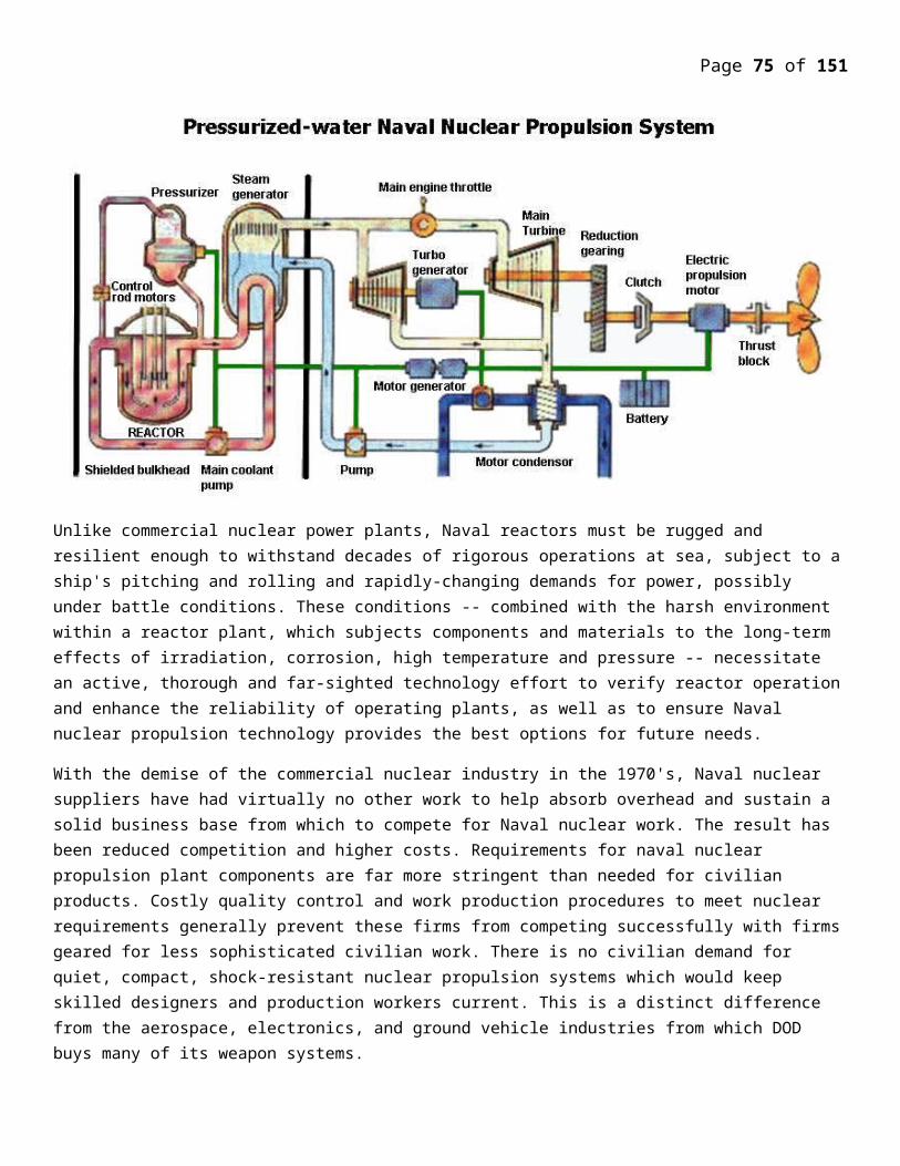
Page 75 of 107
Substituting this value in the expression of the reactivity, and the expression for the regeneration factor, we get:
For equilibrium Xenon:
Inserting the last equation for the expression for the reactivity we get:
Dividing numerator and denominator by σaX we get:
The parameter: at 20 degrees C, and has units of the flux [neutrons/(cm2.sec)].
The expression for the reactivity is written in terms of φ as:
For a reactor operating at high flux, Φ ≈ Ψ and we can write:
For a reactor fueled with U235, ν =2.42, p= ε =1, the value for ρ for equilibrium xenon is:
or a negative 2.74 percent.
REACTOR DEAD TIME
A unique behavior occurs to the xenon after reactor shutdown. Although its production ceases, it continues to build up as a result of the decay of its iodine parent. Therefore the concentration of the xenon increases after shutdown. Since its cross section for neutrons is so high, it absorbs neutrons and prevents the reactor from being restarted for a period of time denoted as the reactor dead time. In a land based reactor, since the xenon eventually decays, after about 24 hours, the reactor can then be restarted. In naval propulsion applications, a naval vessel cannot be left in the water unable to be restarted, and vulnerable to enemy attack by depth charges or torpedoes. For this reason, naval reactor cores are provided with enough reactivity to overcome the xenon negative reactivity after shutdown.To analyze the behavior, let us rewrite the rate equations for iodine and xenon with ψ equal to 0 after shutdown:
dI( t )/dt = -λI I( t) and dX( t)/dt =
Using Bateman's solution, the iodine and xenon concentrations become
Substituting for the equilibrium values of X0 and I0 we get:
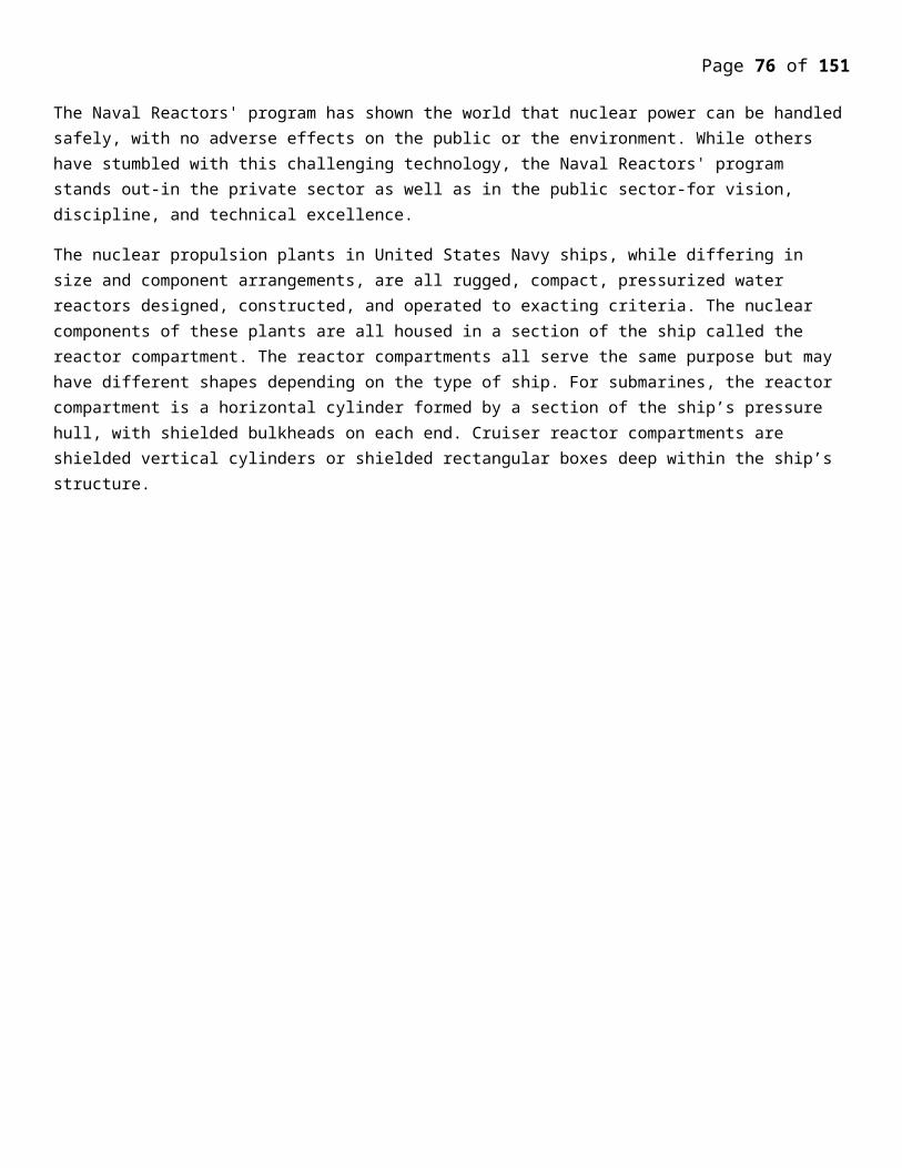
Page 76 of 107
The negative reactivity due to xenon poisoning is now a function of time and is given by:
Figure 8 shows the negative reactivity resulting from xenon after reactor shutdown. It reaches a minimum value, which occurs at about 10 hours after shutdown. This post shutdown reactivity is important in reactors that have operated at a high flux level. If at any time after shutdown, the positive reactivity available by removing all the control rods is less than the negative reactivity caused by xenon, the reactor cannot be restarted until the xenon has decayed. In Fig. 8, at an assumed reactivity reserve of 20 percent, during the time interval from 2.5 hours to 35 hours, the reactor cannot be restarted. This period of 35-2.5 = 32.5 hours is designated as the “Reactor Dead Time.”
This reactor dead time is of paramount importance in mobile systems that may be prone to accidental scrams. This is more important at the end of core lifetime, when the excess reactivity is limited. For this reason, mobile reactors necessitate the adoption of special design features, providing the needed excess reactivity to override the negative xenon reactivity, such as the use of highly enriched cores.
In land based systems such as the CANDU reactor, booster rods of highly enriched U235 are available to override the xenon dead time after shutdown, leading to a higher capacity factor. Power fluctuations induced to follow demand in any power reactor lead to xenon oscillations without any reactor shutdown. The changes of xenon concentrations due to load following are compensated for by adjusting the chemical shim or boron concentration in the coolant, and by control rods adjustments.
ESTIMATION OF NECLEAR WASTE GENRATION BY REACTOR:
Figure 8. Negative reactivity due to xenon poisoning. Flux = 5x10¹⁴ [n/(cm2.sec)].
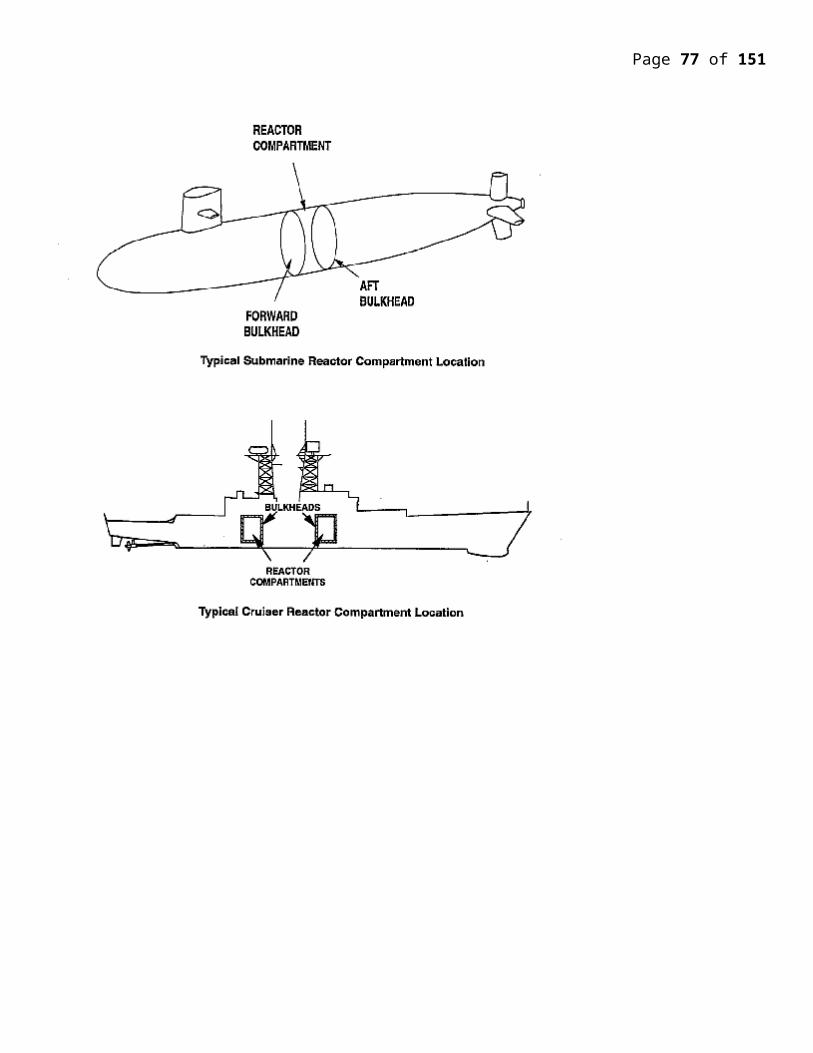
Page 77 of 107
Radioactive waste typically comprises a number of radioisotopes: unstable configurations of elements that decay, emitting ionizing radiation which can be harmful to humans and the environment. Those isotopes emit different types and levels of radiation, which last for different periods of time.The radioactivity of all nuclear waste diminishes with time. All radioisotopes contained in the waste have a half-life—the time it takes for any radionuclide to lose half of its radioactivity—and eventually all radioactive waste decays into non-radioactive elements (i.e., stable isotopes). Certain radioactive elements (such as plutonium-239) in “spent” fuel will remain hazardous to humans and other creatures for hundreds or thousands of years. Other radioisotopes remain hazardous for millions of years. Thus, these wastes must be shielded for centuries and isolated from the living environment for millennia. Some elements, such as iodine-131, have a short half-life (around 8 days in this case) and thus they will cease to be a problem much more quickly than other, longer-lived, decay products, but their activity is therefore much greater initially. The two tables show some of the major radioisotopes, their half-lives, and their radiation yield as a proportion of the yield of fission of uranium-235.The shorter a radioisotope's half-life, the more radioactive a sample of it will be. The opposite also applies; for instance, 96% of the element Indium in nature is the In-115 radioisotope, but it is considered non-toxic in pure metal form and mainly like a stable element because its multi-trillion-year half-life means that a relatively minuscule portion of its atoms decay per unit of time. The energy and the type of the ionizing radiation emitted by a radioactive substance are also important factors in determining its threat to humans. The chemical properties of the radioactive element will determine how mobile the substance is and how likely it is to spread into the environment and contaminate humans. This is further complicated by the fact that many radioisotopes do not decay immediately to a stable state but rather to radioactive decay products within a decay chain before ultimately reaching a stable state.The back end of the nuclear fuel cycle, mostly spent fuel rods, contains fission products that emit beta and gamma radiation, and actinides that emit alpha particles, such as uranium-234, neptunium-237, plutonium-238 and americium-241, and even sometimes some neutron emitters such as californium (Cf). These isotopes are formed in nuclear reactors.It is important to distinguish the processing of uranium to make fuel from the reprocessing of used fuel. Used fuel contains the highly radioactive products of fission (see high level waste below). Many of these are neutron absorbers, called neutron poisons in this context. These eventually build up to a level where they absorb so many neutrons that the chain reaction stops, even with the control rods completely removed. At that point the fuel has to be replaced in the reactor with fresh fuel, even though there is still a substantial quantity of uranium-235 and plutonium present. In the United States, this used fuel is stored, while in countries such as Russia, the United Kingdom, France, Japan and India, the fuel is reprocessed to remove the fission products, and the fuel can then be re-used. This reprocessing involves handling highly radioactive materials, and the fission products removed from the fuel are a concentrated form of high-level waste as are the chemicals used in the process. While these countries reprocess the fuel carrying out single plutonium cycles, India is the only country known to be planning multiple plutonium recycling schemesLong-lived radioactive waste from the back end of the fuel cycle is especially relevant when designing a complete waste management plan for spent nuclear fuel (SNF). When looking at long term radioactive decay, the actinides in the SNF have a significant influence due to their characteristically long half-lives. Depending on what a nuclear reactor is fueled with, the actinide composition in the SNF will be different.An example of this effect is the use of nuclear fuels with thorium. Th-232 is a fertile material that can undergo a neutron capture reaction and two beta minus decays, resulting in the production of fissile U-233. The SNF of a cycle with thorium will contain U-233. Its radioactive decay will strongly influence the long-term activity curve of the SNF around 1 million years. A comparison of the activity associated to U-233 for three different SNF types can be seen in the figure on the top right.The burnt fuels are thorium with reactor-grade plutonium (RGPu), thorium with weapons-grade plutonium (WGPu) and Mixed Oxide fuel(MOX). For RGPu and WGPu, the initial amount of U-233 and its decay around 1 million years can be seen. This has an effect in the total activity curve of the three fuel types. The absence of U-233 and its daughter products in the MOX fuel results in a lower activity in region 3 of the figure on the bottom right, whereas for RGPu and WGPu the curve is maintained higher due to the presence of U-233 that has not fully decayed.
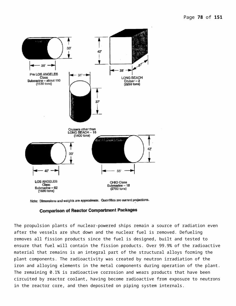
Page 78 of 107
The use of different fuels in nuclear reactors results in different SNF composition, with varying activity curves.Nuclear waste is generated by different steps in fuel cycle followed in Indian nuclear program as shown belowAT present there are three types of NUCLEAR REACTORES IN INDIA (1) Kind of nuclear power reactors(2) Research reactors(3) Fast breeder reactors (Construction)
Uranium tailings
Removal of very low-level waste
Uranium tailings are waste by-product materials left over from the rough processing of uranium-bearing ore. They are not significantly radioactive. Mill tailings are sometimes referred to as 11(e)2 wastes, from the section of the Atomic Energy Act of 1946 that defines them. Uranium mill tailings typically also contain chemically hazardous heavy metal such as lead and arsenic. Vast mounds of uranium mill tailings are left at many old mining sites, especially in Colorado, New Mexico, and Utah.
Low-level waste
Low level waste (LLW) is generated from hospitals and industry, as well as the nuclear fuel cycle. Low-level wastes include paper, rags, tools, clothing, filters, and other materials which contain small amounts of mostly short-lived radioactivity. Materials that originate from any region of an Active Area are commonly designated as LLW as a precautionary measure even if there is with only a remote possibility of being contaminated with radioactive materials. Such LLW typically exhibits no higher radioactivity than one would expect from the same material disposed of in a non-active area, such as a normal office block.
Some high-activity LLW requires shielding during handling and transport but most LLW is suitable for shallow land burial. To reduce its volume, it is often compacted or incinerated before disposal. Low-level waste is divided into four classes: class A, class B, class C, and Greater Than Class C (GTCC).
Intermediate-level waste
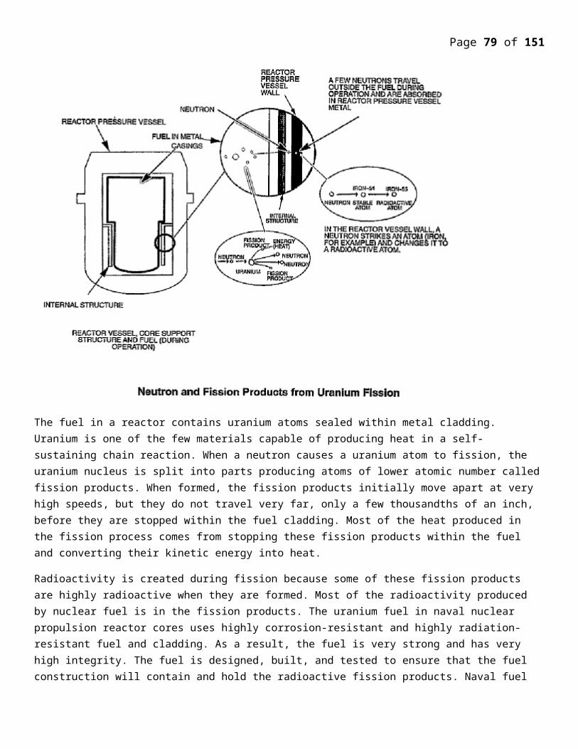
Page 79 of 107
Spent fuel flasks are transported by railway in the United Kingdom. Each flask is constructed of 14 in (360 mm) thick solid steel and weighs in excess of 50 tons
Intermediate-level waste (ILW) contains higher amounts of radioactivity and in some cases requires shielding. Intermediate-level wastes includes resins, chemical sludge and metal reactor nuclear fuel cladding, as well as contaminated materials from reactor decommissioning. It may be solidified in concrete or bitumen for disposal. As a general rule, short-lived waste (mainly non-fuel materials from reactors) is buried in shallow repositories, while long-lived waste (from fuel and fuel reprocessing) is deposited in geological repository. U.S. regulations do not define this category of waste; the term is used in Europe and elsewhere.
High-level waste
High-level waste (HLW) is produced by nuclear reactors. It contains fission products and transuranic elements generated in the reactor core. It is highly radioactive and often thermally hot. HLW accounts for over 95 percent of the total radioactivity produced in the process of nuclear electricity generation. The amount of HLW worldwide is currently increasing by about 12,000 metric tons every year, which is the equivalent to about 100 double-decker buses or a two-story structure with a footprint the size of a basketball court. A 1000-MW nuclear power plant produces about 27 tonnes of spent nuclear fuel (unreprocessed) every year.[24]
Transuranic waste
Transuranic waste (TRUW) as defined by U.S. regulations is, without regard to form or origin, waste that is contaminated with alpha-emitting transuranic radionuclides with half-lives greater than 20 years and concentrations greater than 100 nCi/g (3.7 MBq/kg), excluding high-level waste. Elements that have an atomic number greater than uranium are called transuranic ("beyond uranium"). Because of their long half-lives, TRUW is disposed more cautiously than either low- or intermediate-level waste. In the U.S., it arises mainly from weapons production, and consists of clothing, tools, rags, residues, debris and other items contaminated with small amounts of radioactive elements (mainly plutonium).
Under U.S. law, transuranic waste is further categorized into "contact-handled" (CH) and "remote-handled" (RH) on the basis of radiation dose measured at the surface of the waste container. CH TRUW has a surface dose rate not greater than 200 Roentgen equivalent man per hour (to millisievert/hr), whereas RH TRUW has a surface dose rate of 200 Röntgen equivalent man per hour (2 mSv/h) or greater. CH TRUW does not have the very high radioactivity of high-level waste, nor its high heat generation, but RH TRUW can be highly radioactive, with surface dose rates up to 1000000 Röntgen equivalent man per hour (10000 mSv/h). The U.S. currently disposes of TRUW generated from military facilities at the Waste Isolation Pilot Plant.
Nuclear waste of India is classified into following categories.
(1) Potential Active Waste (PAW)
(2) LLW (1 & 2)
(3) ILW
(4) HLW
Categorization of Waste
Page 80 of 107
(1) PAW (POTENTIAL ACTIVE) A < 10-6 (cl/m3) Activity level No shielding required
(2) Low level waste
(a)LLW 1 10_6 A < 10_3
(b) LLW 2 10_3 < A <10_1 May require Shielding
(3) ILW (Intermediate low level) 10_1 < A < 10+ 4 Shielding necessary
(4) HLW (high level waste) A > 10+4 Shielding & cooling necessary
If there is high level radioactive waste then it is easier to Monitor, Regulate and secure
And repository will provide for a long term isolation and storage of used nuclear fuel
Nuclear waste Management
Our plants generate very low quantity of radioactive waste. The spent fuel containing High level radioactivity is not considered as waste because it produces valuable fuel for future reactors. Spent fuel is sent for reprocessing for extraction of plutonium, uranium and other useful isotopes. High level waste is immobilized by verification in boron glass matrix encapsulated in stainless steel doubled walled canisters for interim storage for 30 years under surveillance in concrete vault lined with stainless Steel for decay of radio activity .Ultimate waste shall be disposed off in deep underground geological repository with protective barriers.
Waste generated in power reactors are calculated on the basis of power generated and in case of research reactors the basis can be 1 rated capacity 2 Average capacity factor, safe management is required for radioactive waste. Its disposal caused more public concern than any other type of waste we should know amount of nuclear waste is produced in our country?
Nuclear fuel cycle in India begins with mining and Milling of uranium and processing of mined uraniumin to U238.This is followed by fuel fabrication and use in research and power reactors the resulting spent fuel is processed to recover uranium and plutonium.
Page 81 of 107
At each stage of this cycle, different kind of nuclear Waste are produced
The Management of Nuclear Waste depends upon its radioactive and other physical and chemical Properties
Page 82 of 107
Reprocessing?
If the used fuel is later reprocessed, it is dissolved and separated chemically into uranium, plutonium and high-level waste solutions. About 97% of the used fuel can be recycled leaving only 3% as high-level waste. The recyclable portion is mostly uranium depleted to less than 1% U-235, with some plutonium, which is most valuable.
Arising from a year's operation of a typical l000 MWe nuclear reactor, about 230 kilograms of plutonium (1% of the spent fuel) is separated in reprocessing. This can be used in fresh mixed oxide (MOX) fuel (but not weapons, due its composition). MOX fuel fabrication occurs in Europe, with some 25 years of operating experience. The main plant is in France, and started up in 1995. Japan's slightly smaller plant is due to start up in 2012. Across Europe, over 35 reactors are licensed to load 20-50% of their cores with MOX fuel.
The separated high-level wastes - about 3% of the typical reactor's used fuel - amounts to 700 kg per year and it needs to be isolated from the environment for a very long time.
Major commercial reprocessing plants are operating in France and UK, with capacity of almost 5000 tonnes of used fuel per year, - equivalent to at least one third of the world's annual output. A total of some 90,000 tonnes of spent fuel has been reprocessed at these over 40 years.
Immobilising high-level waste
Solidification processes have been developed in several countries over the past fifty years. Liquid high-level wastes are evaporated to solids, mixed with glass-forming materials, melted and poured into robust stainless steel canisters which are then sealed by welding.
Page 83 of 107
Borosilicate glass from the first waste vitrification plant in UK in the 1960s. This block contains material chemically identical to high-level waste from reprocessing. A piece this size would contain the total high-level waste arising from nuclear electricity generation for one person throughout a normal lifetime.
The vitrified waste from the operation of a 1000 MWe reactor for one year would fill about twelve canisters, each 1.3m high and 0.4m diameter and holding 400 kg of glass. Commercial vitrification plants in Europe produce about 1000 tonnes per year of such vitrified waste (2500 canisters) and some have been operating for more than 20 years.
Loading silos with canisters containing vitrified high-level waste in UK, each disc on the floor covers a silo holding ten canisters
A more sophisticated method of immobilising high-level radioactive wastes has been developed. Called 'SYNROC' (synthetic rock), the radioactive wastes are incorporated in the crystal lattices of the naturally-stable minerals in a synthetic rock. In other words, copying what happens in nature. This process is still being developed for specialist application.
Waste disposalFinal disposal of high-level waste is delayed for 40-50 years to allow its radioactivity to decay, after which less than one thousandth of its initial radioactivity remains, and it is much easier to handle. Hence canisters of vitrified waste, or used fuel assemblies, are stored under water in special ponds, or in dry concrete structures or casks, for at least this length of
time.
The ultimate disposal of vitrified wastes, or of used fuel assemblies without reprocessing, requires their isolation from the environment for a long time. The most favoured method is burial in stable geological formations some 500 metres deep. Several countries are investigating sites that would be technically and publicly acceptable, and in Sweden and Finland construction is proceeding in 1.9 billion year-old granites.
One purpose-built deep geological repository for long-lived nuclear waste (though only from defence applications) is already operating in New Mexico, in a salt formation.
After being buried for about 1000 years most of the radioactivity will have decayed. The amount of radioactivity then remaining would be similar to that of the corresponding amount of naturally-occurring uranium ore from which it originated, though it would be more concentrated.
Page 84 of 107
Layers of protection To ensure that no significant environmental releases occur over a long period after disposal, a 'multiple barrier' disposal concept is used. The radioactive elements in high-level (and some intermediate-level) wastes are immobilized and securely isolated from the biosphere. The principal barriers are:
Immobilise waste in an insoluble matrix, eg borosilicate glass, Synroc (or leave them as uranium oxide fuel pellets - a ceramic).
Seal inside a corrosion-resistant container, eg stainless steel.
Surround containers with bentonite clay to inhibit any groundwater movement if the repository is likely to be wet.
Locate deep underground in a stable rock structure.
For any of the radioactivity to reach human populations or the environment, all of these barriers would need to be breached, and this would need to happen before the radioactivity decayed to innocuous levels.
What happens in USA and Europe?
In the USA high-level civil wastes all remain as used fuel stored at the reactor sites. It is planned to encapsulate these fuel assemblies and dispose of them in an underground engineered repository at Yucca Mountain, Nevada. This is the program which has been funded by electricity consumers to US$ 32 billion so far (ie @ 0.1 cent per kWh), of which about US$ 6 billion has been spent.
In Europe some used fuel is stored at reactor sites, similarly awaiting disposal. However, much of the European spent fuel is sent for reprocessing at either Sellafield in UK or La Hague in France. The recovered uranium and plutonium is then returned to the owners (the plutonium via a MOX fuel fabrication plant) and the separated wastes (about 3% of the spent fuel) are vitrified, sealed into stainless steel canisters, and either stored or returned. Eventually they will go to geological disposal.
Sweden represents the main difference. It has centralised used fuel storage at CLAB near Oskarshamn, and will encapsulate used fuel there for geological disposal at a new repository at Forsmark by about 2023. Since 1988 it has had an intermediate-level waste repository there. Finland is building a final repository at Olkiluoto. European funding is at a slightly higher level than in USA, per kWh.
Approaches to radioactive waste disposal:
Waste disposal is discarding waste with no intention of retrieval. Waste management means the entire sequence of operations starting with generation of waste and ending with disposal. Solid waste disposal, of waste such as municipal garbage, is based on three well-known methods, namely landfills, incineration and recycling. Sophisticated methods of landfills are adapted for radioactive waste also. However, during incineration of ordinary waste, fly ash, noxious gases and chemical contaminants are released into the air. If radioactive waste is treated in this manner, the emissions would contain radioactive particulate matter. Hence when adapted, one uses fine particulate filters and the gaseous effluents are diluted and released. Recycling to some extent is feasible. We have already dealt with the reprocessing approach, whereby useful radioactive elements are recovered for cyclic use. But it still leaves some waste that is a part of the high-level radioactive waste.
Radioactive waste management involves minimizing radioactive residues, handling waste-packing safely, storage and safe disposal in addition to keeping sites of origin of radioactivity clean. Poor practices lead to fu-ture problems. Hence choice of sites where radioactivity is to be managed safely is equally important in addition to technical expertise and finance, to result in safe and environmentally sound solutions.
Page 85 of 107
The International Atomic Energy Agency (IAEA) is promoting acceptance of some basic tenets by all coun-tries for radioactive waste management. These include:
(i) Securing acceptable level of protection of human health;
(ii) Provision of an acceptable level of protection of environment;
(iii) While envisaging (i) and (ii), assurance of negligible effects beyond national boundaries;
(iv) Acceptable impact on future generations; and
(v) No undue burden on future generations. There are other legal, control, generation, safety and management aspects also.
Next we review some approaches for radioactive waste disposal.
To begin with, the radioactive waste management approach is to consider the nature of radioactive elements involved in terms of their half-lives and then choose the appropriate method of handling. If the concentrations of radioactive elements are largely short-lived, then one would resort to what is referred to as ‘delay and decay’ approach; that is, to hold on to such a waste for a sufficiently long time that the radioactivity will die in the meanwhile. A second approach is to ‘dilute and disperse’ so that the hazard in the environment is minimized. But when the radioactivity is long-lived, the only approach that is possible is to ‘concentrate and contain’ the activity. In order to carry out concentrating the waste (generally the sludge), chemical precipitation, ion exchange, reverse osmosis and natural or steam evaporation, centrifuging, etc. are resorted to. The resulting solids are highly concentrated in radioactivity. In the following we shall discuss some of the approaches that are being advocated or are currently in practice.
However, to the extent that the mining operations result in ‘bringing the radioactivity to the surface and change its chemical and physical form that may increase its mobility in the environment’, they assume importance in radioactive waste management. Long-lived iso-topes like 230Th, 226Ra, the decay products of uranium are part of the tailings and hence the tailings have to be contained.
Low-level radioactive waste and even transuranic waste is often buried in shallow landfills. One has to pay attention to any groundwater contamination that may result due to this. The highly radioactive liquid effluents are expected to be ultimately solidified into a leach-resistant form such as borosilicate glass, which is fairly robust in the sense that it is chemically durable, resistant to radiolysis, relatively insensitive to fluctuations in waste com-position and easy to process remotely. (Immobilization in cement matrices or bitumanization or polymerization are also some of the other options that are practised to some extent.) However, it must be noted that plutonium does not bind strongly to the matrix of the glass and ‘thus can be loaded only in trace amounts to prevent the possibility of criticality or recovery for clandestine purposes’. This glass in turn is placed in canisters made of specific alloys. Choice of the canister material would depend on the ultimate site where the waste will be dis-posed-off. For example, if the ultimate disposal is in the oceans, the alloy chosen must have low corrosion rates under the environmental temperature, pressure, oxygen concentration, etc. Studies have been carried out in this respect. For example, it is found that in oxygenated sea water at 250oC, 7 mega Pascals pressure and 1750 ppm of dissolved oxygen, the corrosion rates of 1018 mild steel, copper, lead, 50:10 cupronickel, Inconel 600 and Ticode 12 are 11.0, 5.0, 1.0, 0.7, 0.1 and 0.06 mm/year, respectively.
One seeks to dispose-off the high-level radioactive waste packages contained in multiple metal-barrier can-isters within natural or man-made barriers, to contain radioactivity for periods as long as 10,000 to 100,000 years. ‘The barrier is a mechanism or medium by which the movement of emplaced radioactive materials is
Page 86 of 107
stopped or retarded significantly or access to the radio-active materials is restricted or prevented’. It is obvious that recourse to multiple barriers may assure safety of emplaced radioactivity over long periods of time. The man-made barriers, namely the form to which waste is reduced, for example, in the glassy form, and the canister along with overpackaging, go along with natural barriers. As far as the choice of natural barriers is concerned, land-based mined depositories over fairly stable geologic formations are preferred over disposal in the oceans. However several social and environmental concerns have prevented the land-route being adopted in counties like USA even after 50 years of accumulation of radioactive waste. Therefore proposals have been made to take to the ocean-route and there also the choice varies from just placement of the canisters over the seabed to placement within the sub-seabed sediments and even within the basement rocks.
Options being aired for disposing radioactivityThe following options have been aired sometime or the other. Each one of the options demands serious studies and technical assessments:
• Deep geological repositories • Ocean dumping• Seabed burial • Sub-seabed disposal • Subductive waste disposal method • Transforming radioactive waste to non-radioactive stable waste • Dispatching to the Sun.
Major problems due to legal, social, political and financial reasons have arisen in execution due to
• Environmental perceptions • Lack of awareness and education • ‘Not-in-my-backyard’ syndrome • ‘Not-in-the-ocean’ syndrome • Lack of proven technology
Geologic disposal Geologic disposal in deep geological formations – whether under continental crust or under seabed – as a means of radioactive waste disposal has been recog-nized since 1957, for handling long-lived waste. Quite often, contrary to views expressed by environmentalists, it is ‘not chosen as a cheap and dirty option to get the radioactive waste simply “out of-site and out of mind”’.
The deep geological sites provide a natural isolation system that is stable over hundreds of thousands of years to contain long-lived radioactive waste. In practice it is noted that low-level radioactive waste is generally disposed in near-surface facilities or old mines. High-level radioactive waste is disposed in host rocks that are crystalline (granitic, gneiss) or argillaceous (clays) or salty or tuff. Since, in most of the countries, there is not a big backlog of high-level radioactive waste urgently awaiting disposal, interim storage facilities, which allow cooling of the wastes over a few decades, are in place.
Ocean-dumping For many years the industrialized countries of the world (e.g. USA, France, Great Britain, etc.) opted for the least expensive method for disposal of the wastes by dumping them into the oceans. Before 1982, when the United States Senate declared a moratorium on the dumping of radioactive wastes, the US dumped an estimated 112,000 drums at thirty different sites in the Atlantic and Pacific oceans.
Page 87 of 107
Though this practice has been banned by most of the countries with nuclear programmes, the problem still persists. Russia, which currently controls sixty per cent of the world’s nuclear reactors, continues to dispose of its nuclear wastes into the oceans. According to Russia’s Minister of Ecology, it will continue to dump its wastes into the oceans because it has no other alternative method. It will continue to do so until it receives enough international aid to create proper storage facilities. In response, the United States has pledged money to help Russia, but the problem continues.
Although radioactive waste has known negative effects on humans and other animals, no substantial scientific proof of bad effects on the ocean and marine life has been found. Hence some nations have argued that ocean-dumping should be continued. Others argue that the practice should be banned until further proof of no harm is available.
Oceanic Disposal Management Inc., a British Virgin Islands company, has also proposed disposing of nuclear and asbestos waste by means of Free-Fall Penetrators. Essentially, waste-filled missiles, which when dropped through 4000 m of water, will embed them-selves 60–80 m into the seabed’s clay sediments. These penetrators are expected to survive for 700 to 1500 years. Thereafter the waste will diffuse through the sediments. This was a method considered by the Scientific Working Group (SWG) of the Nuclear Energy Agency (NEA) during the eighties. Penetrator disposal is potentially both feasible and safe, its implementation would depend on international acceptance and the development of an appropriate international regulatory framework. Neither of these ex-ists, nor are they likely to in the foreseeable future. The penetrator method has also been further constrained by a recent revision of the definition of ‘dumping’, by the London Dumping Convention, to include ‘any deliberate disposal or storage of wastes or other matter in the seabed and the subsoil thereof’.
Sub-seabed disposal
Seabed disposal is different from sea-dumping which does not involve isolation of low-level radioactive waste within a geological strata. The floor of deep oceans is a part of a large tectonic plate situated some 5 km below the sea surface, covered by hundreds of metres of thick sedimentary soft clay. These regions are desert-like, supporting virtually no life. The Seabed Burial Proposal envisages drilling these ‘mud-flats’ to depths of the order of hundreds of metres, such bore-holes being spaced apart several hundreds of metres. The high-level radioactive waste contained in canisters, to which we have referred to earlier, would be lowered into these holes and stacked vertically one above the other interspersed by 20 m or more of mud pumped in. The proposal to use basement-rock in oceans for radioactive waste disposal is met with some problems: variability of the rock and high local permeability. Oceanic water has a mixing time of the order of a few thousand years which does not serve as a good barrier for long-lived radionuclides.
Since experiments cannot be conducted to assure safety of seabed disposal on the basis of actual canisters deposited in the seabed over periods of interest, namely over hundreds of thousands of years, model calculations have been performed to predict the capabilities of such a disposal option. The model approach has started with selection of sites and acquisition of site-specific data using marine geological methods. These sites are away from deep-sea trenches, mid-oceanic ridges or formation zones where geological activities are high. These sites are also far away from biologically productive areas in the oceans.
The sediments in chosen sites are fine-grained and are called ‘abyssal red clay’. These sites are believed to have desirable barrier properties with ‘continuous stable and depositional histories’. Therefore these potential waste repositories are geologically stable over periods of the order of 107years and are likely not to have human activities, as they are not resources of fishes or hydrocarbons or minerals. Core samples from most Pacific and Atlantic sites have been studied to investigate thermal, chemical and radiological effects. It is found that when sea water and sample sediment mixtures are heated at 300oC at high pressure, the solution pH changes from 8 to 3. Calculations suggest that ‘less than 2 cubic metres of untreated sediment would be needed to neutralize all the acid generated in the thermally
Page 88 of 107
perturbed region of about 5.5 m3’. The canister material has to be compatible with this type of environment for periods of at least 500 years by which time fission fragment activity would become acceptable. Similarly, other calculations have taken into account sediment–nuclide interactions to determine ion concentration around a buried source as a function of time.
Experimental work has already established that clays have the property of holding on to several radioactive elements, including plutonium; hence, seepage of these elements into saline water is minimal. Rates of migra-tion of these elements over hundreds of thousands of years would be of the order of a few metres. Hence, during such long times, radioactivity will diminish to levels below the natural radioactivity in sea water due to natural radioactive decay. The clays also have plastic-like behaviour to form natural sealing agents. Finally, the mud-flats have rather low permeability to water; hence, leaching probability is rather low.
It may be noted that the method depends on standard deep-sea drilling techniques routinely practised and sealing of the bore-holes. These two aspects are well-developed, thanks to the petroleum industry and also because of an international programme called the Ocean Drilling Programme. Core samples from about half a dozen vastly separated sites in the Pacific and Atlantic oceans have ‘showed an uninterrupted history of geo-logical tranquillity over the past 50–100 million years’.
However there are questions that remain to be answered:
• Whether migration of radioactive elements through the ocean floor is at the same rate as that already measured in the laboratories?
• What is the effect of nuclear heat on the deep oceanic-clays? • What is the import on the deep oceanic fauna and waters above? • In case the waste reaches the seabed-surface, will the soluble species (for example, Cs, Tc, etc.) be di-luted to
natural background levels? If so, at what rate? • What happens to insoluble species like plutonium? • What is the likelihood of radioactivity reaching all the way to the sea surface? • In problems of accidents in the process of seabed burial leading to, say, sinking ships, to loss of canisters, etc.
how does one recover the waste-load under such scenarios? • What is the likelihood that the waste is hijacked from its buried location? • Added to these technical problems are others: • International agreement to consider seabed-burial as distinct from ‘ocean-dumping’. • This method would be expensive to implement, but its cost would be an impediment to any future plutonium-
mining endeavour.
Although the world trend is toward the option of landbased disposal, it is doubtful whether restricting repositories to land-based sites really helps prevention of sea pollution. If radionuclides from a land-based repository leached out to the surface, they would be quickly transported to the sea by surface water. What is essential is to isolate radionuclides from the biosphere as reliably as possible. If sub-seabed disposal results in more reliable isolation, sub-seabed disposal is the better safeguard against sea pollution. This method takes into consideration technological feasibility, protection of marine environments, and availability of international understanding.
The United Nation’s Convention on the Law of the Sea delineates that a coastal state is granted sovereign rights to utilize all resources in water and under the seabed within its exclusive economic zone (EEZ), which can extend from the coast line up to 200 nautical miles (about 370 km) offshore. A repository is proposed to be constructed in bedrock 2 km beneath the seabed. To utilize sub-seabed disposal within the EEZ, it is also proposed that waste packages would be
Page 89 of 107
transported through a submarine tunnel connecting land with the sub-seabed repository. Sea pollution by an accident during disposal work would be improbable, because waste would never go through sea water during the work. The proposed method is a variation of geologic disposal. Long-term monitoring is also possible by maintaining the access tunnel for some time after constructing artificial barriers.
While sub-seabed disposal of nuclear waste-filled canisters thrown from vessels apparently is regulated by the London Convention, it is not prohibited or regulated by the London Convention when accessed via land-based tunnels. Sweden has been practicing this method of sub-seabed disposal since 1988, when a repository for reactor wastes was opened sixty metres below the Baltic seabed. This project has been widely cited by politicians from other countries as a great example of solving the nuclear waste problem. Because of Sweden’s initiative, nuclear waste is already being deposited under the seabed. Other countries could follow Sweden’s example and dispose-off nuclear waste under the seabed via land-based tunnels.
Subductive waste disposal method This method is the state-of-the-art in nuclear waste disposal technology. It is the single viable means of disposing radioactive waste that ensures non return of the relegated material to the biosphere. At the same time, it affords inaccessibility to eliminated weapons material.
The principle involved is the removal of the material from the biosphere faster than it can return. It is considered that ‘the safest, the most sensible, the most economical, the most stable long-term, the most environmentally benign, the most utterly obvious places to get rid of nuclear waste, high-level waste or low-level waste is in the deep oceans that cover 70% of the planet’.
Subduction is a process whereby one tectonic plate slides beneath another and is eventually reabsorbed into the mantle. The subductive waste disposal method forms a high-level radioactive waste repository in a subducting plate, so that the waste will be carried beneath the Earth’s crust where it will be diluted and dispersed through the mantle. The rate of subduction of a plate in one of the world’s slowest subduction zones is 2.1 cm annually. This is faster than the rate (1 mm annually) of diffusion of radionuclides through the turbidite sediments that would overlay a repository constructed in accordance with this method. The sub-ducting plate is naturally predestined for consumption in the Earth’s mantle. The subducting plate is constantly renewed at its originating oceanic ridge. The slow movement of the plate would seal any vertical fractures over a repository at the interface between the subducting plate and the overriding plate.
Transmutation of high-level radioactive waste This route of high-level radioactive waste envisages that one may use transmutational devices, consisting of a hybrid of a subcritical nuclear reactor and an accelerator of charged particles to ‘destroy’ radioactivity by neutrons. ‘Destroy’ may not be the proper word; what is effected is that the fission fragments can be transmuted by neutron capture and beta decay, to produce stable nuclides. Transmutation of actinides involves several competing processes, namely neutron-induced fission, neutron capture and radioactive decay. The large number of neutrons produced in the spallation reaction by the accelerator are used for ‘destroying’ the radioactive material kept in the subcritical reactor. The scheme has not yet been demonstrated to be practical and cost-effective.
Solar option It is proposed that ‘surplus weapons’ plutonium and other highly concentrated waste might be placed in the Earth orbit and then accelerated so that waste would drop into the Sun. Although theoretically possible, it involves vast technical development and extremely high cost compared to other means of waste disposal. Robust containment would be required to ensure that no waste would be released in the event of failure of the ‘space transport system’
Page 90 of 107
Nuclear power inevitable optionDiversified energy resources-base is essential to meet energy security, with limited resources of coal and oil available in country and with growing concern of green house Gases generated by fossil fuel fired station ,nuclear power will be called up on to play a greater role in medium and long term perspective.
Long Term Nuclear Power program India long term nuclear is based on utilizing he vast indigenous Thorium resources for electricity generation Indian uranium resources can support the finest stage program of 10,000 MWe based on pressurized heavy water reactor (PHWRS)
Using natural uranium as a fuel and heavy water as moderator and coolants. The energy potential of uranium can be increased to 3,00,000MWe in the second stag through fast breeder reactors which utilize plutonium obtained from the recycled spent fuel for the first stage using U-233.With the deployment of thorium in third stage using U233 as a fuel ,the energy potential of for electricity generation is large and substantial. Indigenous industrial infrastructure for the reactor program is well developed. Special infrastructure for the production of fuel ,Heavy water reactor control and instrumentation have been developed within the Department of Atomic Energy. Indian Industry has gained valuable experience and reached a stage of maturity in manufacturing components for these reactors .
Ensuring Environmental ProtectionProtection of plants personnel, the environment and public concern is primary importance
In design, construction of the nuclear power stations .The radiation sources are adequately shielded, monitored and all operation and constant maintenance works on the active systems are carried out strictly according to approved world standard procedures.
The release of radioactivity to the environment from nuclear power stations is in very
Small quantities well within limit fixed by Atomic Energy Regulatory
Board the dose is equivalent to one time x-ray chest done in 20 years, that it is most safe. Safety of reactors is ensured by adopting defense in depth philosophy is followed which leads multiple barriers diversity redundancy independence and fail safe design of safety related systems.
LMFBR (Liquid metal fast breeder reactors)
Man entered the age of nuclear power after the conference of in Geneva on 1955 one of the most important question discussed in the convention was “ Breeder Reactor “ The most common naturally occurring fissionable material that can serve as fuel for a reactor for nuclear reactor is U 235. Unfortunately U235 makes up only 1/7100 of per cent ie. 1/710000th of fuel natural Uranium. But the idea that the more plentiful U238 could be burned by converting it into fissionable Plutonium, open a great opportunity. This type of reactor is called a “Breeder Reactor”.
In theory the possibilities are perfectly simple. All one needs is to supply sufficient neutrons to continue the chain reaction and also to manufacture Plutonium from U238. Plutonium itself is the best source of neutrons for when a
Page 91 of 107
plutonium captures a high energy neutron and fissions, its fission yields, on average also 2.9 neutrons a better yield than from fission of U235. In a reactor utilizing plutonium fuel which of course must be made from U238 with the neutrons from initial change of U235) one of the neutrons from each plutonium fission would sustain a chain reaction and most of the remainder 1.9 neutrons can presumably be captured by U238 to produce new plutonium atoms. Since number of plutonium atom manufactured is greater than the number destroyed, as time goes on the amount of fuel in the breeder reactor will increases.
Likewise Thorium could be basis of similar breeding cycle, when a thorium captured neutrons, the reaction results in a formation of atom of the fissionable isotope U233. The conversion of thorium to U233 does not require fast neutrons as the manufacture of plutonium does. It can be carried out with low energy thermal neutrons. This considerably simplifies the problems in designing the reactors. However, there is also a downside in U233 cycle the neutron economy is tighter, for U233 release only 2.3 neutrons instead of 2.9. In case of thorium elaborate experiments to demonstrative feasibility of breeding are less necessary. The fundamental nuclear constants are known quite accurately. The critical mass is about 20 kilogram of U233 for slow neutrons reactor. Taking all data together, it is possible to predict reliability that a power reactor can be built which will operate area U233 breeder.
For India which is starved of U235 but has abundance of thorium, this fact opens up tremendous possibilities. Thus if nuclear marine propulsion has to becomes a reality in this country which is both economical and sustainable the system has to be base on a thorium fast breeder cycle.
In a U238 Plutonium cycle fast breeder reactor the fission of U235 release 2.5 neutrons per atom. One of these neutrons must be captured by another U235 atom to maintain chain reaction and for breeding so succeed, better than one of the remaining 1.5 neutrons must be captured by U-238 to make plutonium. Particular case has to be taken to minimize neutron losses to minimum and ensure as many as possible find their way in to U-238 atoms. Its reactor is tiny about the size of football. Because there is no materials used in the reactor to slow down neutrons all absorb some neutrons, this reactor has no moderator it operates with fast neutrons. Around the core is a blanket of U238 which catches neutrons to form Plutonium.
All the reactor power is generated as heat in this small core. The coolant is liquid metal an alloy of sodium and potassium. This alloy doesn’t appreciably absorb neutrons and has excellent characteristics as a heat transfer medium. It is liquid at room temperature but has a high boiling point of 1500⁰C. It is however, extremely chemically active it burns vigorously when exposed to air and explodes in contact with “water”. It is also highly radioactive because of its exposed to neutrons. Hence it must be handled carefully. It is at 680⁰C when it emerges from the reactor. The heat transfer in the reactor is a most sophisticated technology. Since the reactor yields 4 kw/ in 3. To handle the radioactive liquid metal, special pumps, values, flow meters, and other instrumentations needs to be designed. One of these is the unique “electromagnetic pumps” without moving parts. It operates much like an induction motor. Electromagnetic force move the liquid metal through a duct much in the same way the force the rotor of induction motor to run.
In the so called electromagnetic pumps advantage is taken of the electrical conductivity of liquid metal to force it flow in a pipe under the influences of magnetic field. The motive force act as per Lenz Law and lorentz Left Hand Rule. In electromagnetic pumps the liquid metal in the conductor which passes through a duct located between the poles of the electromagnetic. The force exerted on the conductor by the magnetic field causes the flow to take place. This design is important not only because of nature of liquid being pumped but also because pumps may be contaminated by sodium which is radioactive.
The sodium alloy Nak doesn’t attack Stainless steel, Nickels many nickel alloy or beryllium at temperature below 680⁰c . At higher temperatures mass transfer can occur. In Nak there is no danger of solidification either inside or outside
Page 92 of 107
reactor. For reactor with high thermal fluxes such as the “ fast breeder reactor “ operating at high temperature liquid metals are choice for coolants. Their heat transfer characteristics is superior to that of water, so that it is possible to achieve same rate of heat removal with small areas of contact. They have excellent thermal properties e.g. high thermal conductivity and low vapour pressure and have relatively high specific heat and volumetric heat capacities. They are stable at central radiation field and at high temperature capacity.
For ordinary fluids, the principle mechanism of heat transport is by effect of temperature, as a result of which a “ Parcel” of fluid is rapidly moved from region close to hot wall to the main body of .... fluid. In liquid metal .................. thermal transfer occur mainly by molecular conduction. Where as this mechnaism may provide 70% heat transfer for liquid metal, it contributes only0.21% to transfer in water. This means than ........ boundary thickness, which is important for .............. is not significant for liquid metals.
The energy released during fission process appears in various forms that mainly as............... energy of the fission fragnents this fission nutrons and beta particals resulting from the radio dicay of the fission products. The fission fragments are usually stopped within the fuel ............ the small .................... into the dedding and .................. only by about 0.01 . The beta particale of high energy may .............. upto 4 mm in dudding material such as aluminium, and so large fracation of the .................. of their particles may escape from the fuel element into surronding. In ................. U-235 reactor may will enter the ................. escape the core.
The fission nutrons loose most of their energy in fist few collisions. Thus most of the heat from there sources ends consideration comprising of 90% or more of energy generated will be released within the core.
In a reactor using rodium or sodium potasium alloy Nak as collant ti may be desirable to interpore a liquied such as molten led or mercury loops ............... the sodium and boiling water. This has a major safety advantage of avoid the violent chemical reactons leading to an explain and also source a purpose of reducing the volums that has to shielded because of γ –radioatoms from Radioactive Na-24 produce by nutorns capture in the reactor.
Nuclear Green has in the past offered sketches of the early history of reactor design. The classic reactor design was created by Enrico Fermi, and featured a solid core. Fermi was a physicist, and in a way designed his first reactor as a physics experiment. From the view point of process, materials were placed in the nuclear core and then mechanically removed. What happened to the materials after their removal was not a part of the physicists business. There is no doubt that Fermi was the god father of the Sodium cooled fast breeder reactor. The late World War II Manhattan Project New Piles Committee, of which Fermi was a member discussed breeder options.
The World War II Metallurgy Lab of the University of Chicago was the nursery for both Argonne National Laboratory and Oak Ridge National Laboratory. Argonne basically was formed from Fermi's staff, and was lead by a long time Fermi protegee, Walter Zinn. As early as 1944, Fermi who was convinced of the importance of the breeder reactor project as a future source of energy, suggested to Zinn that he and his subordinates begin to develop sodium cooled breeder reactor technology. Alvin Weinberg described Zinn as the gray eminence of nuclear development.
Argonne National Laboratory under Zinn was originally intended to be the center of national reactor design, although ORNL was to emerge as its rival during the 1950's. Weinberg notes,
WALTER (“WALLY”) HENRY ZINN was Enrico Fermi’s close associate during the Manhattan Project. After World War II he became the leading U.S. figure in the earliest development of nuclear energy. So pervasive was his stamp on nuclear
Page 93 of 107
development that a proper obituary to Walter Zinn must be nothing short of an account of the origins of nuclear energy and how Zinn profoundly affected its development.
Weinberg who was himself an important figure in the history of nuclear developments thus points out the importance of Zinn's role. While Weinberg was responsible for the suggestion to Hyman Rickover that the Light Water Reactor would prove more suitable for submarine propulsion than a sodium cooled reactor would, it was to Argonne and its director, Walter Zinn that Rickover turned to superintend its development. Zinn had a Rickover size ego, and when Rickover tried to control the Argonne group managing submarine reactor development. Zinn through Rickover out of Argonne, and Rickover retaliated by moving the submarine reactor project to Bettis Laboratory, controlled by Westinghouse.
Zinn was to leave Argonne in 1956 after pushing through the Experimental Breeder Reactor-1 (EBR-1) project. Zinn's departure from Argonne followed a serious accident with the EBR-1 and Zinn's future focus was on Light Water Reactors. Argon researchers continued to investigate liquid metal breeder technology.
Thus the initial prestige of the fast breeder concept was to rest primarily on Fermi's shoulders, with Walter Zinn playing an important role. Yet the Fast Breeder was problematic from the start. A report issued by Sandia Laboratory in 2007 focused on Liquid Metal Fast Breeder sodium related safety issues/ the report notes numerous safety hazards for Sodium cooled reactors. Among notable sodium related safety hazards are sodium fires, and the positive void coefficient reactivity hazard of sodium cooled reactors. Sodium firers can be caused by sodium contact with
* air* water* and concrete
The Sandia Report focuses on the void problem
A fundamental difference between water and sodium-cooled reactors is the void reactivity coefficient. If the water around the core is voided (boiled, drained) in a water-cooled (thermal) reactor during operation, the power level will automatically drop. The reactor is therefore said to have a negative void reactivity coefficient. In contrast, if sodium is voided in certain sodium-cooled fast reactors (particularly large reactors), it will cause the power level of the reactor to rapidly increase. This reactor is said to have a positive void reactivity coefficient. When the reactor power increases, it can lead to additional boiling and voiding until fuel melts. This positive feedback can lead to extremely rapid surges in reactor power, potentially damaging or melting fuel and cladding.
Multiple events can lead to core voiding during operation, and great care is taken in the proposed new reactors to ensure that these events are prevented. They include sodium boiling, loss of coolant accidents (LOCA), and gas bubble entrainment within the sodium. Sodium fires could lead to sodium boiling if an undercooling event is initiated without scram (reactor shutdown). A severe leak in the secondary system, perhaps coupled with cable fires could lead to this situation. A large leak in the primary system could also disrupt flow enough to induce sodium boiling in the core. A sodium leak in the primary system could also lead to either a LOCA or gas bubble entrainment event. A large primary leak could potentially uncover a portion of the core. If gas is pulled back into a leak in the primary system, the resulting bubbles could also reach the core.
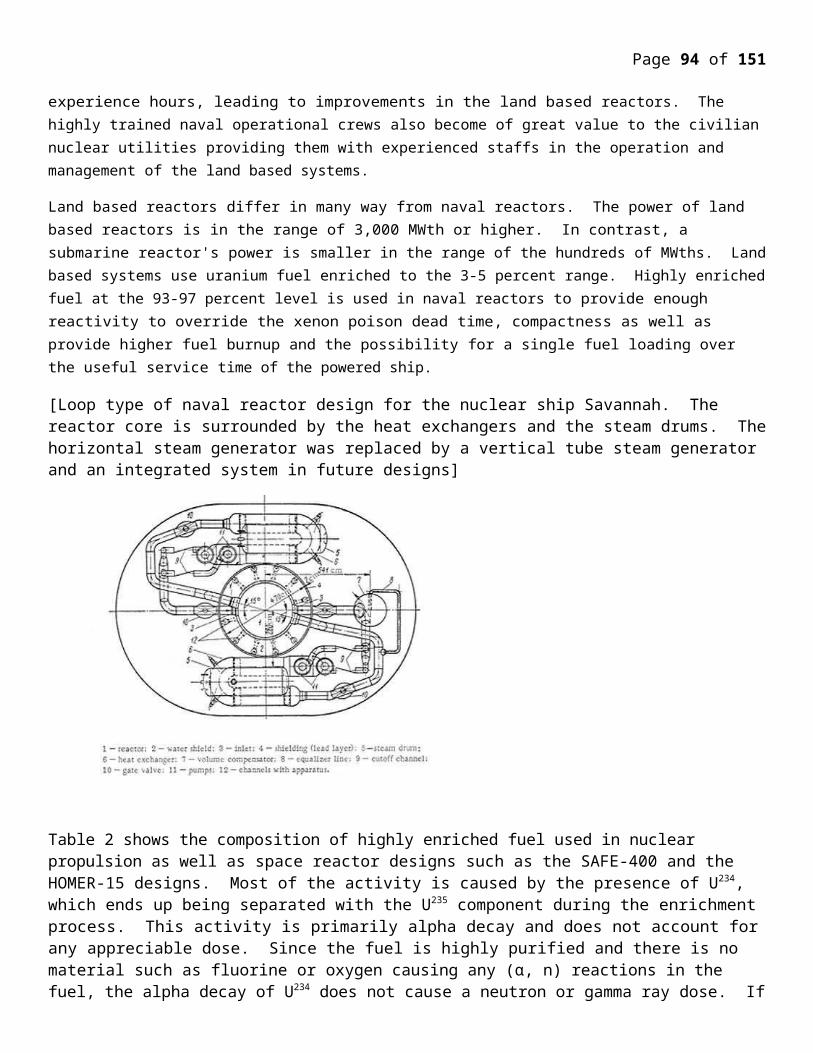
Page 94 of 107
Many of the problems of sodium cooled reactors were still unknown to Ed Bettis and his associates in 1947 when K-25 Physicist Cecil Ellis assigned them the task of developing a sodium cooled reactor for a nuclear powered aircraft. But as Ed Bettis later explained even then enough was known to understand that a sodium cooled reactor would be difficult to control as well as potentially dangerous.
There were significant problems with sodium cooled reactors, as Ed Bettis was to later explain:
By 1950, at various places in the country, work had progressed on the handling of high- temperature sodium metal to the point that it was being seriously considered as a coolant for nuclear reactors. Accordingly, a group of engineers and physicists at ORNL started design work on a solid-fuel-pin sodium-cooled reactor, with the fuel consisting of 235U (as UO2) canned in stainless steel. It was decided to make this a thermal reactor and to use BeO blocks as the moderator. The circulating sodium was to extract heat from the fuel pins and at the same time to remove heat from the moderator blocks. . . .
The solid-fuel-pin thermal reactor design was found to possess a serious difficulty when the design concept was projected to cover a relatively high-power reactor. The problem was the positive temperature coefficient of reactivity associated with the cross section of xenon at elevated temperatures.. . .
The Xenon problem was serious enough to force Bettis and his associates to look at an alternative.
This xenon instability was considered to be serious enough to warrant abandoning the solid-fuel design concept, because of the exacting requirement placed on any automatic control system by this instability.
But what sort of alternative reactor would solve the Xenon issue?
An obvious way to avoid the control problem would be to incorporate a liquid fuel that would have a large density change for a given change in temperature. If, upon heating and expanding, a portion of the fuel could, in effect, be made to leave the critical lattice, a self- stabilizing reactor would result.
Bingo! Ed bettis and his associates had discovered one of several MSR advantages, its self stabilization.
In 1950 the K-25 aircraft nuclear propulsion program was turned over to Fairchild Aircraft. which decided to move it to Ohio. The program staff was given a choice of following the program to Ohio, or to remain in Oak Ridge, where a new nuclear powered aircraft program was to emerge superintended by ORNL. A Brilliant Chemist, Raymond Clair Briant was to be the new Program manager, and Bettis approached Briant about the Molten Salt Reactor concept, and so the ORNL Molten Salt Reactor adventure was born.
In an often noted 1957 paper, "Molten Fluorides as Power Reactor Fuels"Alvin Weinberg proposed the construction of a liquid fluoride salts based thermal breeder reactor. The very concept than Weinberg announced was revolutionary. In 1959 the AEC commissioned an evaluation of three potential fluid fuel reactor technologies capable of breeding. They were"
* Aqueous Homogeneous Reactors
* A Liquid Metal Fast Breeder with a slurry rather than a solid fuel core
* The Molten Salt Breeder Reactor
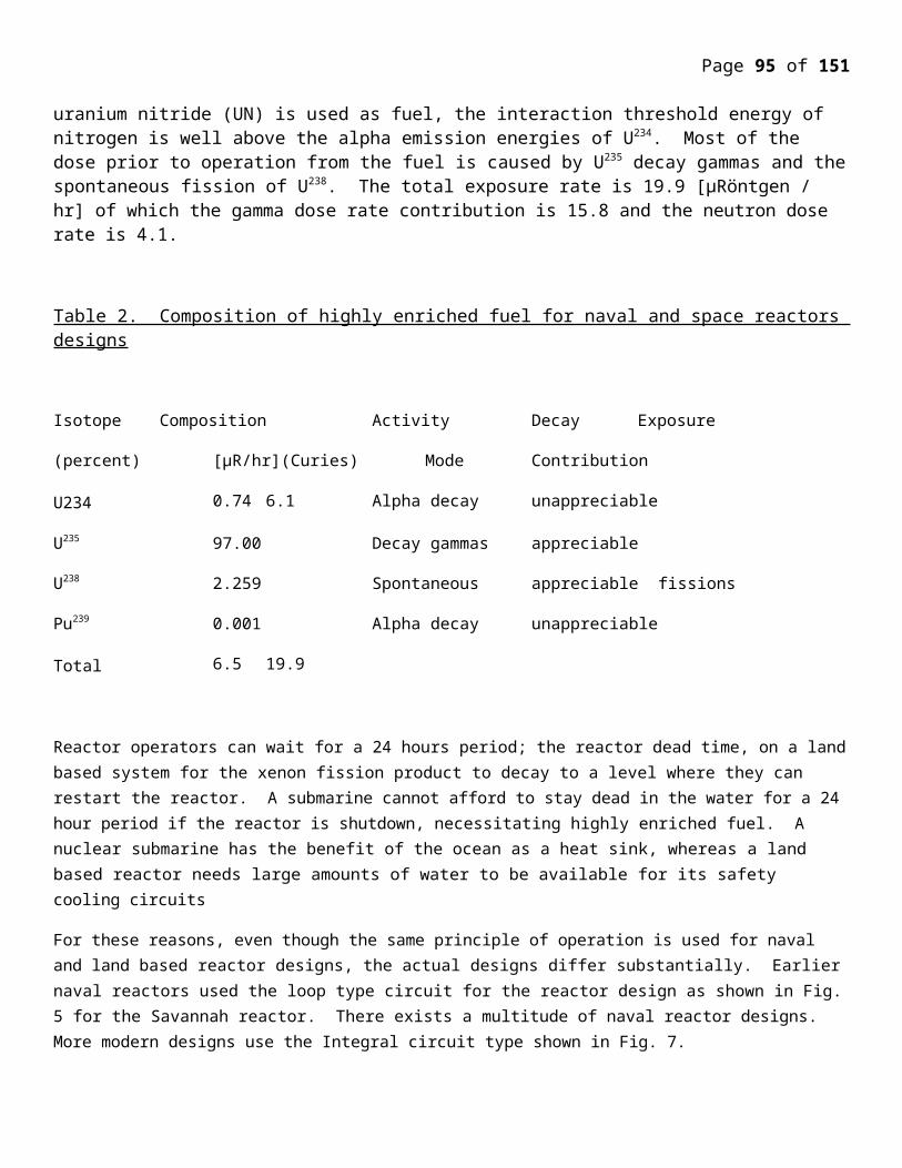
Page 95 of 107
Of the three the committee commissioned to write the report concluded that the MSR represented the smallest developmental challenge. Unfortunately the AEC did not also commission a direct comparison between the MSR and the standard Liquid Metal Fast Breeder Reactor. Had they done so they would have found that the Molten Salt Reactor was a far more practical reactor concept than the Liquid Metal Fast Breeder Reactor. This statement can be tested by comparing the developmental problems of the two MSR prototypes with the developmental histories of the early liquid sodium cooled breeders. While both MSR's performed as expected, with no major accidents this was not the case with early sodium cooled fast breeders. Compared to the Molten Salt Reactor, the LMFBR faced daunting and expensive to fix safety challenges. A list of major LMR accidents will be sufficient to make this point.
* The EBR-1 suffered a partial core melt down in 1955.
* The Fermi 1 suffered a partial core meltdown in 1966
* The Sodium Reactor Experiment suffered a partial core meltdown in 1959
In addition to these major accidents, LMFBRs have suffered numerous lessor accidents including sodium leaks with fires, and fuel cladding ruptures. I am not going to argue that these accidents mean that LMFBR are unsafe, or that safety progress has not been made in LMFBR design. Rather my point is that the MSR posed far fewer safety challenges than the LMFBR did in 1959, and a direct comparison of the two breeder technologies would have revealed this fact.
But safety was hardly the only area in which the MSR held advantages. In terms of materials problems, ORNL was able to come up with solutions quickly once problems were known. Thus in the early 1960's ORNL possessed a potential breeder technology that was safer than the more conventional LMFB and a technology that was likely to pose far fewer developmental challenges. There is evidence that the AEC was interested in the development of MSR technology. But that began to change with the arrival of LMFBR fan Glenn Seaborg as AEC Chairman, Milton Shaw, another LMFBR supporter, as AEC reactor Czar, and with the emergence of another LMFBR supporter, Congressman Chet Holifield, as a controlling influence over AEC policy. None of these people people would have favored a point by point comparison of the prospects of LMFBR and MSR technology. The decision to favor the LMFBR was thus political, and was not based, nor was it justifiable, on scientific or rational grounds.
The fast breeder reactor has the highest flux of neutrons known to man-650 million. Million nutrons per square inch per second . This creates a secure problem, because high nutrons flux makes down the physical structure of all materials and equipments exposed to it including uranium itself. . This high nutrons flux of fast fast nutrons in the fast breeder reactor ...... produces. .................. effects 1. Thermal Spike 2. Displacement Spike 3. Chnage in material property due to nutrons.
Tharmal Spike :- When the structureal element of on material atoms impacted by these higher energy nutrons and charged particles, transfer of energy takes place from the particles to group of atom in the close ............ These ................. atom produced by an energetic k............ has sufficient energy to cause it undergo vibration of large amplified without leaving its lattice. position ... some of these excess u...... energy will be rapidly transferred to its immideate ........... which will ............. transfer some more energy to their neighbes . The result will be formation of limited region in which the atom will have vibrational energytic in excess of the
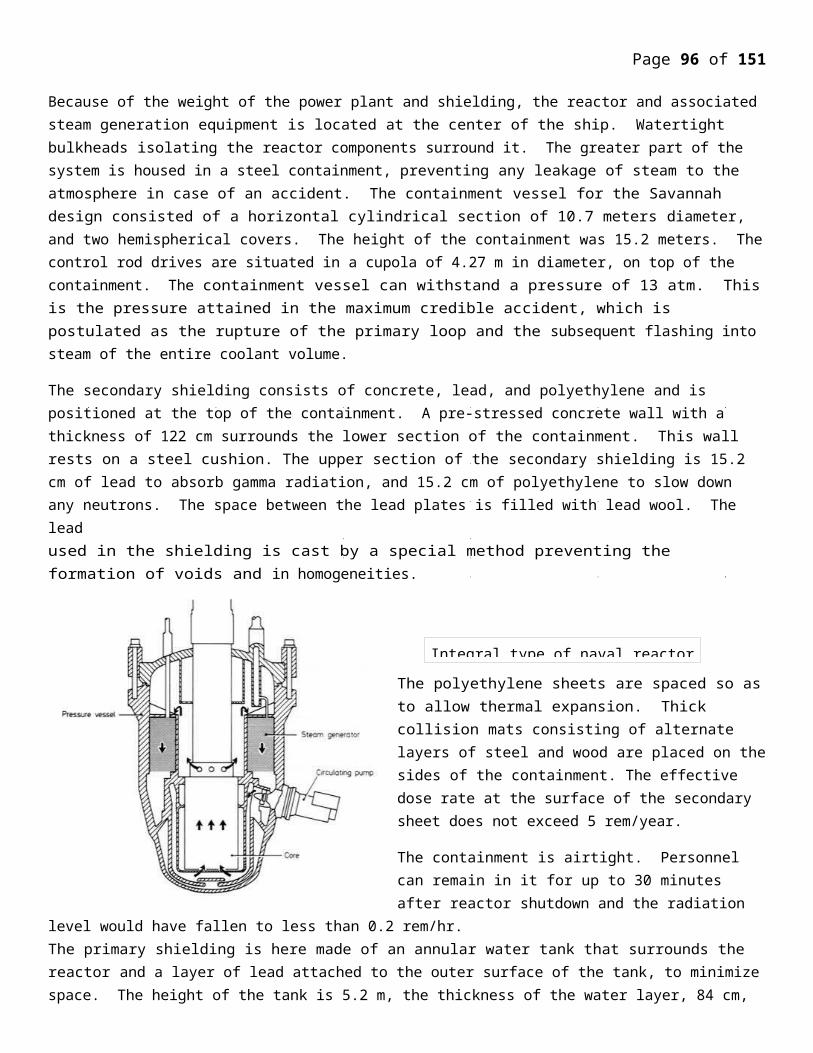
Page 96 of 107
normal values corresponding to the bulk. Tempreture of the solid. It has .......... estimated that in such a situation a region containing a order of 1000 atoms is heated to a tempreature of 1000. C for a period of 10 -10 sec. This is refered to a “ thermal spike “ so that not many of the atoms leave the equilibrium .... At higher temperature of the thermal spike the distrubution of the lattice expansion in to the expectd. Due to the rapid cooling due to conduction of heat to surrounding atom a contain amount of dis...... will be “ frozen” since there may not be sufficient time for all atom to relocate to the equilibrium position. As a consequence stresses may be develops in the material.Displacement Spike : - On the other hand of the vibrational energes are sufficient to persuit a large numbers of atoms leave their lattice side and m about as a result of thier collisions a “ displacement spike” is produced. As a consequence, there would be formed a “ spike containing a large number of .............Change of meterial properties due to nutrons captures : - The capture of nutrons by ....... can produce an introduction of impuric atom. The immideats produce of the such a reaction in an isotop with absorb element so there should be not damage to imediated substance, but if the product is rardioactive is frequently the case, it will emit beta particle and be ............................. into different elements. In addition fast nutrons can produce new element directly by (n1 p) and (n, 2n ) reaction. AS a result of there nuclear reactions imputity atoms are produced in the original crystalian ...... After a long ex...... ..... to their fast nutrons in a reactro, a sufficient number of atoms may accumulated to affect the physical properties of the material. However, radiation damage is less effective than tharmal and displacemnt spikas. Some of the radiation damage can result in d............... in ductility and mereace in ...................strength.Every reactor system must ime.................. include a certain amount of structrual material which serve as mechanical trancework and structural c............... The require of a structural metarial will way to some extent wiht type of reactor and its specific purpose in reactor. ......... chemical propulsion like inside strength, impact stength and ....... stress must adequate for the operating condition. The meterials must be capable of using fabricated or joined into the required shapes. Thermal conductivity should be high and the coefficient of thermal expansion low or well matched with that of other meterial/ In many reactor components there is considerable internal heating due to either fission or slowing down of fast nutrons, or due to the absorbtion of various radioactives. The removal of heat from exterior results in a high temperature gradients with metarial . Thuis such meterial therefore be able to mantain stability under ........ thermal stresses. In addition to physical and mechanical properties .............. to above the nuclear properties must be satisfactory. If the mateial is to be used in ......... the core or reflactor of the reactor, it must ............ have small.............. for nutron capture and should be maroated that metarial that ............ used in thermal reactor because of large ........ perhaps can be employed inthe fast reactor, since the capture of fast neutrons may then be tolerable. As a result of nutrons capture many metarial become readioactive and consequently are dengare to handle. There are mentenance and reparing equipment expored to nutorn flux of the reactor. .......... be aa difficult problem. The quantity of fissible material relative to structural components in a fast reactor is much greater, consequently the ratio f the macroscopic fission cross section to that of par....... capture .............. to be larger. As a result structural material with fastly large cross section, which could not be ............ in the theraml system, can be used in fast reactors.

Page 97 of 107
The essential requirements for materials are now high melting point, relation of satisfactory physical and nechanical property at high temperatures, and good cossossion resistance especially to molten rodiumethals and alloys of particular ................. are stainless stands, mobium, moly b.................. tantalum and tugston. The later two leaving very high melting point substances, for ex tantulum is 3400 , thier theromal nutron croos section are very high and they are brit.......... and .................... difficult to fabricate. Tantalun on the other hand, can be fabricated without ......................... difficulty and resists the action sodium upto 1000.c, it can also contain molten plutonium iron fuel. .Austentic stainless steel of .................... 304, 304.c, 309S Nb, 31B, 316L, 347 are found suitable for reactor applications . Nickle used for manufacture of these stainless shall less than 0.0012% of .................................................... of radioactive Co-60 . They should be able to resist intergranular attack, of re.............. material, stress corresion cracking stress corrosion ...............................In operation of fast breeder reactor, an important conception the breeding ratio. The “ breeding ration is the amount of fissible plutonium -239 produces compaired to amount of fissinable metarial like U-235 used to produce it. In the liquid metal fast breeder reactor in the breeding ........... is 1.4 but the result have been achieved to above 1.2. The tiem required for a breeder reactor to produce enough metarial to ............. a second reactor is called doubling time. At present the design plan target about 10 years as the doubling time. The reactor core consists of thounds of stainless steel tubes containing a mixture of uranium and plutonium oxides, about 15-20% fissionable plutonium -239. Surrouding core region called the breeder blanket consisting of tubes filled with only uranium opxide. The cool............... temperature in p................. load condition exceedes 500.c
Optimum breeding allows about 75% of the of natural uranium to be used comparied to 1% in standered light water reactor.
The core of fast breeder reactor are much more compact than light water reactors. Plutonium or more high enriched uranium is used as fuel, the fuel elements are smaller in diameter and they are clad in stainless steel instead of z.................. Due to liquid metal coolent operating .......... below boiling point these reactors are operated at pressure very near to atomospheric pressrues. Besides liquid sodium alloy, has following advantage of low pumping ................ required, it has ability to absorbs considerable energy during emergancy condition, it has a tendncy to react with a dissolve sseveral fission products that may be release into coolant ......... fuel elements failure there by .............There are two basic design of fast breedar reactor the pool ( integreated ) layout and the loop type. In the pool type, layout, the reactor vessel not only contains the .......... but also the number of component. The reactor vessel is filled wiht sodium at approximately atmospheric pressreu and the core refuling machines, primary coolant pumps and .................. exchange are imersed in it. Therefore ,,,,,,,,,,,,,,,, sodium collant circuit is lockaed in the same vessel. This design make it possible to reduce appreciably the external piping. The second tlype of layout, known as the loop design is more like that of concestional light water reactor in ...................... indiuidual componatns of the colling system are outside the reactor vessel itself contain only the core and ........ equipment . The either arrangements, the vessel ........... primary system components are .............. by gaurd vessels so that any .............of primary system circuit docuit ............... large leak of radioactive sodium in surrounding.
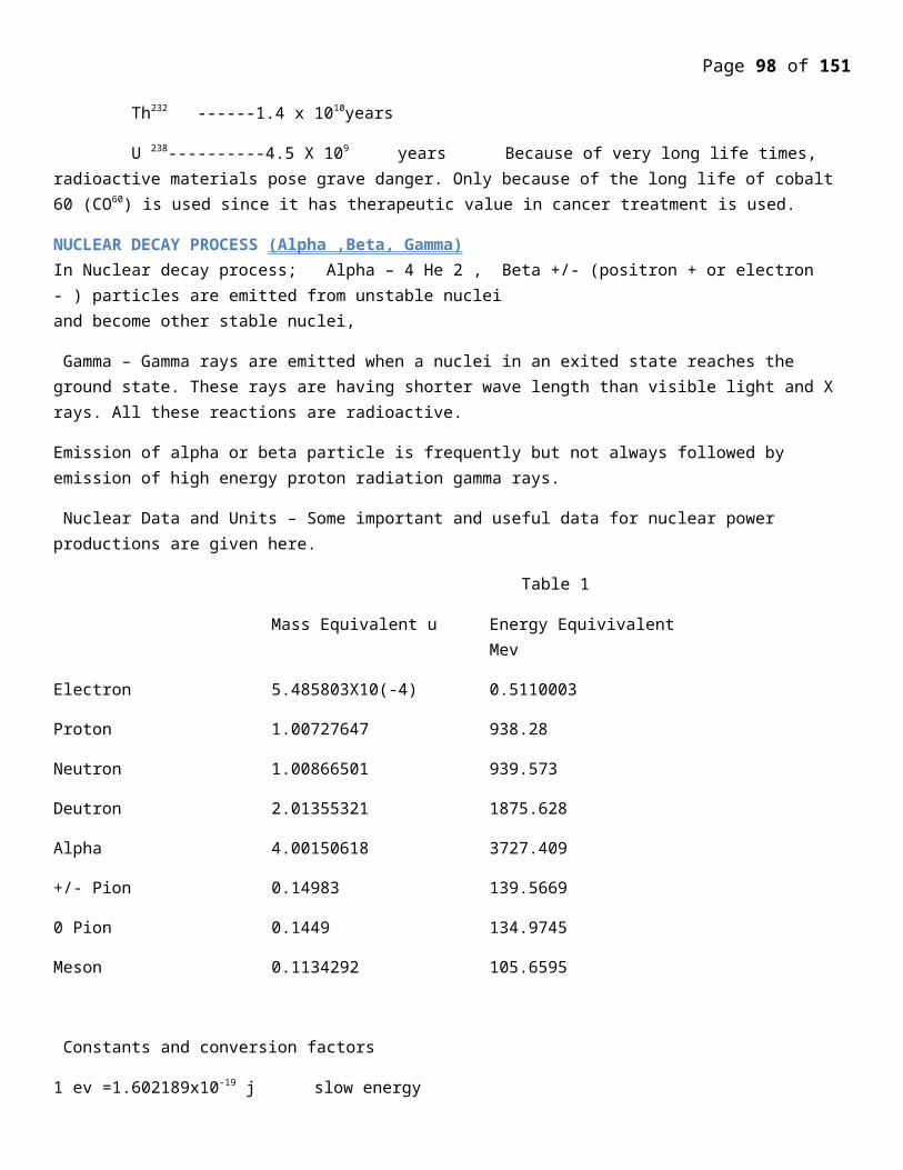
Page 98 of 107
In any fast breeder reactor wiht sodium cooling system the aim is to minimise the shut down time required by the reactor. Both in the pool or loop type of layout the use is ..... frequent of a rotating plug located on top of the reactor vessel inthe closure ..............
The in vessel fuel transfer ma...................... on this toatating plug. The control had ..... are also mounted on this plug is noted . It is thus possible to transfer the fuel from the core to any point inside the reactor and ............... using the fuel transfer machine. In the pool layout, the ....... fuel is normaly placed in a temporary storage drums located inside the reactor and ................ suing the the fuel transfer machine, in which is remains while the decay heat is removed from fission products acitivity. The ex vessel fuel transfer machine is used later to transfer fuel to storage outside the reactor vessel. . This can be affected with reactor in operation. In loop type the spent fuel is transfered directly from the core to storage facilities outside. An important problem in fst breeder reactors is the ............. life of the fuel. In thermal reactos only a small percentage of the uranium atom in the fuel fission before it is removed from the core to the ........ fuel storage or reprocess normally, the amount of fissible metarial in high fuel is not more than 1% and since the ....... to fission c........ ratio is small, they attain ...... up of only 2 or 3% . At higher ............. there may be damage to fuel metal cladding some fuel failure. In fast transfer 15% or ...... of fuel is fissible material and since breeding ration exceeds .................... up is not ..........to the amount of fessible material procucts, instead by resistance to radiation on dameage the typical ...... up may attain 10-15%. A particular ........ with such high ....... is that the stainless steel caldding may l. To stock and ....... thus damaging the fuel rod and even blocking the coolant flow relatively compact LMFBR are implies a greator nutron flux through the core stuck than typically occur in the thermal heat ............. rise to possibiltya and alternation of core confeguration occure a period of time. Rests are typically included in the LMFBR core design in order to present such changes. In general the possibility of changes in core configuration is more of concern in a fast reactor than in thrmal reactor. Changes in core geometry could more more energy result in significant changes in the multiplication factor leading to concern about this possibility of a core ........... accident. This is aggreveted by the fact that development of a .............. in cooling coolant ( due to boiling etc) reduces absorbtion and moderation of nutron, boteh leading to in ............. in multification factor in a fast reactor. ( In a thermal reactor the .......... reduces .......... factor ) care must be taken that the design presents significant .......... feed back. Mechnamism are sufficient to present coolant ........... at least those that can propAgate to affect large portions of the core. In latter mechanisams are bscially nintended to provided a decrease in multiplication factor or ............. as the tempreature .......
An important contributor .................... cofficient for fast reactor in the “ Doppeler effect , as the tempretaure ...... the effectivness of ........... capture ( without fission) is remaining neutrons from the system is increased so fission rate is decreased.
Finaly concern is also expressed that the prompt neutron lifetime ( the time is taken for a given neutron to be absorbed) an thereby producing a next ................... of neutrons is much shorter for fast reactors than for thermal, this time is about 5x10⁻⁷ ec. .. 1/1000m the comparable life time of thermal nutrons. This should be of greatest concern if the multiplication factor exceded by 1 while the reactor .......
Most reactor design parametericalls to thermal efficiencies of about 40% , breeding ratio of 1.2 or . ....... doubling time of 10 years to maximum 20 years.
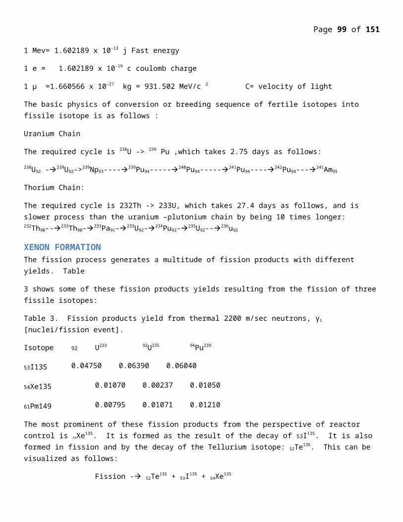
Page 99 of 107
Most LMFBR development has ....... a uranium - plutonium fuel cycle. Because the thorium uranium cycle is surpeior in ................. reactors and satisfactory in fast ...... there may be advantages introducing thorium and ................ 233U into fast reactors anticipated.
While maintain basic ............................. of LMFBR fuel region into a core and blanket there are number of ways to intorduce thorium or U233 Thorium may be used in blanket or the core and U233 may replace part or all of the core Pu239 . Howcver, properties of thorium in metalic form may permit metalic rather than ceramic, fuel rods ( i.e. it is less pyroporic) The absence of Oxygen or Carbon would ......... nuclear properties , even raising the breeding ratio about that ....... with mixture oxide fuel LMFBR. In addition thor ium ............. the ............... coefficient and dopplu coefficients so that the development of ......... in the coolant and rise in tempreature lowers the nutron multiplication factor. , some performance calculation of uranium plutonium and thorium fueld LMFBR shown the once with metal fuel have higher breeding ratios.
Nuclear Propulsion History :-USA : Conceptual analysis of nuclear marine propulsion theries in 1940. Research on developing nuclears recators for the Navy was done at Bettis Atomic Laboratery under the long term leadership of Admiral Hyman G. R. Ricksuer, the first test reactor palnt a p.......... referred to as S........... started up in 1953 at Naval Reactor Facility. The first nuclear ............. vessel the submarines USS nauticles ( SSN-3 was past to sea nin 1955. USS Maritime marks the ............ of submarines from conventional to nuclear )USS Maritime was p........ by SZWreactors the crew trained on SLW readrrs at the naval Reactor Fecing on the c...... Idaho National Laboratoroy (INL)The second nuclear submarine was the Usseawolf ( SSN-575) which was initially passed by a rodium cooled SZG reactor, and supported by laud based S1G reactor at kessal ring site under the k...... atomic power laboratory operated by gaural electric. A spare S2G was also built but never used. USS seawolf was pleagus by super.... problems with the result USS nauticles declered for superior performance. This and the risk passed by liquid rodium in e..... of accident at sea led . Admiral Rickoutr to select PWR ( pre ......... water reactor) as the standard US Naval reactor type. The S2Z was re........... from USS seawolf and replaced by S2Wa reactor using components fron s.............. S2W that was a past of the USS Nauticle program. All subsequent US Naval reactors have le PWR.
Experience with USS Nauticles led to the parallel development of Skate class submarines powered by single reactors, and aircraft carrier , USS Enterprise ( CNN-65) powered by eight A2W reactor ..........in 1960. A ...... USS long beach (CGN-3) .......... in 1961and was powered by two C1W reactor units . R................... USS Enterprises remain in service.
Full scale land based plants in 9 .............. New Yark, and c................... proceeded .................................of US nuclear reactor, although not all of them. After initial consturction some engineering testing was done and proto type .............. used to trained nuclear powered qualification for a many years afterwards. After the skate class vessesl, reactor develop proceeded in USA a single series of standerdised design were ........ with one reactor power ......... used.
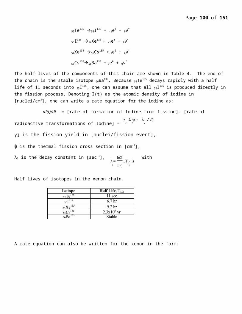
Page 100 of 107
The United State is the main navy with nuclear power aircrafts carriers (10), while Russia has nuclear powered carriers. All the of the ........ of the US Navy nuclear powered aircraft carriers ............... have been ............... and those not only ................by recyling will be recycled.
Russia has got eight nuclear icebroken in service or building. Since its incuption in year 1948, the US Navy nuclear programme has developed 27 different plant designs, installed than on 210 nuclear powered ships, taken 500 reactor cores in operation and accumulated .... 5,400 reactpr uears pf p[eatopm amd 128,000,000 miles safely steained. US Navy has runs experienced a reactor accident.
Congress has manded that the US Navy consider nuclear power as an op tion on large surface combatants ( .................destroyers ) and amplibious .......... ships
Russia ( eastwhile USSR)From the date 1950s through the end of 1994 the Soviet Union an dlater Russia, built a total of 245 nuclear submariners, more than all other ther re included 91 SSB no. ( Submarine, Ba........ Missile Nuclear) In addition to nuclear submarine the Russion nuclear fleet includes four kirov –class guided meissile carriers, a small number nuclear of powered scientific reasearch , support and space ............... vesesl, support, and space ........ vessels and .......... ................. nuclear powered icebreakers.
After the break up .................. these developments have been dis.......... the important bases were lost and Russion defense budget collapse. All non-nuclear Diesel would have been become all non-nuclera diesel vessel beeb ............souit union followed the limited stke in developing nucler power submariners st........... by US development in nauticl nuclear submariners (displayed in 1954) Soviet work on nuclear propulsion reactors began in early 1950, at the institute of pluerics and power engineering .................. under Anatodiy P. Alexander V later to became head of the Kurehatov institute. In 1966 the first Soviet propulstion reactor desinged by ..... team began operation testing. Mean while a design team under Vladimir N. Peredgudov woked on the vessel that would ...............After over coming many obstacles including stean ........... problemsradiation leaks and other difficulties the first nuclear submariners based on that combined efforst the “ lenin sky .............” entered service in 1958. Regular line production of nuclear attack submariners began in 1959.
Nuclear submariners offered significant advantage to Soviet Navy. In ........................... or ranges endurance, durabilitly and s........ In additon, the large power plants increased speed upto 16 -20 knots For their .... the design at............ much better l... conditon than the diesel boats, including fresh water, laundry facilities, shower andbetter iar qualitly.
Since 1950s four g........ of nuclear power submarines and several nuclear power experimental submarines ................. from 1955 to 1965, 55- first geuration nuclear submarines were constructed from four soviet submariner yards s............ admirality skiye, krasooye so.. A........ Z... In the begning of 1980 the sorviet union launched several titanium -hulled submarine production of titanium hulled nuclear submarine have ...... Current submarines in production include third genration ..........
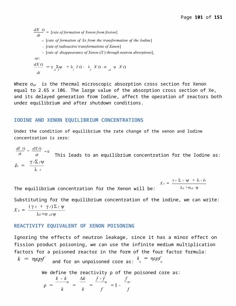
Page 101 of 107
class attack submarines and Oskaz class ........... missile submarines four in generation “ se... class attack submarines, and fiften generation Borey class SSBNs.The Soviet union launched its first nuclear powered ice breaker Lenin in 1957, and since consituted two additional icebreaker classes., to Arktika and “Taymy” classes. In 1993, Russia developed the Ural, a communication vessels powered by 2 icebreaker reactors. Other nuclear powered vessel include Kirov class c. An scientific and space navigational vessels. The four Kprov class cruisers are Admiral . , Admiral Lazaral, Admiral rakinimor and petvelkty . In addition Russion authorities plan are .. floating reactors ........... military vessels currently nota sea, s lpecial purpose vessels,............... to provide power to remote areas.
Fuel fabrication for naval propulsion reactor has taken place only at “ Elekeostal” plant near POSCON. Fuel for nuclear submarines fall under Russion Ministry of Atomic Energy ( ...) which also supercies the entire naval fuel cycle, from delivery of fresh fuel to naval base to the reprocessing of s...fuel from nuclear submarines.
Reactor Desing in USE : -USA : - U. S. Naval reactors are presurerised roator reacrtors, which differ from comercial power reactor.The main parts are : They leave high power duety in a small volume. Some run on highly our.. (>20% U-235) Current U.S. submariners .. fuel enriched to 93%. Fuel is not UO2 or cir.. plates ..metal ziruenium alloy ( 15% U235 wiht 93% cor They have long core lines, so that refiling included only after 10 or more years and new core are designed to last 50 years in carriers and 30 -40 years in submarines. The design enables a compact pressures vessels while maintianing safety.
Long core life is enabled by high uranium enrichment and by e.......... a “ burnable nutron position” which in progressively depleted as non-burnable positions like fission products ac............... accumulates. The loss of burnable . counter balances the creatin of non-burnable .. and result in stble long term fuel efficiency.
Long term integrity of the comact reactor pressure vessel is maintained by producing an internal neutron shield , to present ....... by neutron bombardment.
Reactor size range upto 500Mak in the larger submarines and surface ships.
US Naval ships rely on steam futurbine p.. ... several US surface ships are to carried two or more reactor.
Russia :
Early souviet research in nuclear propulsion reactors forward a dual track.: one oriented towards a water, moderated designs and the other towards the use of heavy metal coolant. Despite of certain start up and operational advantages in using heavy metal as coolant, soviet designers enentually ........ this option due to greater safety hazards involved and difficulty of keeping reactos hot enough while the submarines was in port. R................. the reactors in less then full capacity caused .......... heavy metal to .................. ............. the reactor to seize up and eventually “ f ................... causing implacable damage. For these reserve ............... a few test design the soviet navy opted to produce only water colled reactrors for sue in active duty submarines.
Most soviet designed nuclear power submerine are powered by one or two water colled, ............ water reactor wiht a total thermal capacity of 50 to 200 MWT. Depending on the type of the reactor each reactor contains about 248
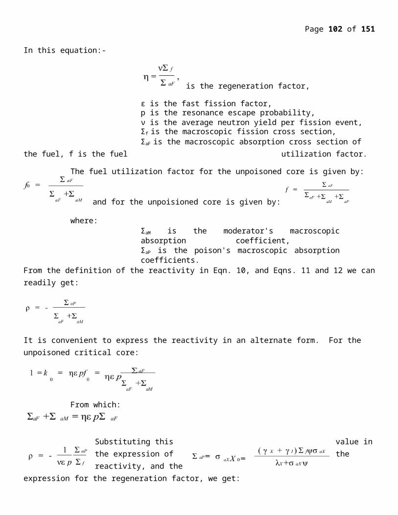
Page 102 of 107
˜252 type fuel assemblies. One fuel assembly holds to ............ of fuel rods ................ can be round or flat. Flat fuel rods enlarge the surface area for improved thermal efficiency are are more common in ............ reactors.
Out of the estimated 468 naval reactors to that have been installed in the 258 submariner and the surface ships, 24 use fuel enriched to 90% U-235 . Third generation reactors have core wiht different ..........................fuel assemblies in the middle section of the reactor are enriched to 21% U-235, while the outermost fuel assemblies are enriched upto 45 percent U-285. A second generation submarine reactor containe about 250 kg. Of Uranium, of wihch 50 kg. are U-238 . Third generation nuclear submarines contain approximately 110 kg of U-235.
Russion Fuel Cycle :-
The Russion naval fleet –signnificantly overlaps the military cycle of the military ....... nutural production and commercial nuclear power reactrors. In the year 1960s to 1970s the nuclear power industry, shipbuilding industry and the Russion Navy established naval fuel cycle infrastructure . During this period french fleet was fabricated in Electrotal from these facilities the fuel was then transproted from there facilities for ref ..... the nuclear fleet abot 1.5 mot pf weapon grade .................. was used for production this fuel for naval and reasearch reactors.
The Uranium component of naval fuel wa recorrded from titium production reactors at ............ in ........... and from H.E.U. rods from plutonium production reactors in Kra................ 2G and Tanisk -7 The RT-1 [;amt om <aul re[rpcessed ................. fuel HEU fuel. Uranium enriched to 50% resourced from HEU fuel was sent to the machine building plant for production of submarine fuel rod and assessemblies. After the fuel core ............................ use in active duty submarines, it was ................... for several years before ............ to Mayak for reprocessing ........naval fuel instument reprocessing together with ............. fuel from the research .......... seperated alumium fuel was stored in Mayak ..................... Uranium from naval reactor ................ to metallurgical plant to produce RBMK fuel .........
In 1950s the fabrication and reprocessing of naval reactor fuel has occured at Mayak. Standard naval reactor f...... is stainless steel or Zirconium ........... cormet material in which the uranium particals are ............. aluminium matrix. From ............. it in shipped to central storage faclilities. Naval fuel is later transfered to service ships for distrubution to operating nuclear submarines.
Physical protection of naval fuel is a matter of concern several dicommissioned reactors act as dicommssioned sepnt fuel storage facilities. Low iriadated fuel in submarines dicommissioned before their service life retains a large quantity of highly enriched uranium (HEU) Seperation of HEU from low irrdiated and spent fuel is much easier than chemical reprocessing required for plutonium seperation. Naval reactor fuel elements assembels are smaller and easier to handle than power reactor fuel assemblies. It is important to note that irradiated fuel in naval reactors require significant cooling time.
Spnt fuel is also kept in service ships, which receive spent fuel assemblis from active duty submarines. During refuelling operations and fron decommsion vessel as a result of d....... and recator shutdown operations. Once the survice ships are filled, the spent fuel is sent to on shore central st orage facilities where it is ........................ ............ for three years. There is a.... of service ships and .................................... special .... are required to carrly ....... f ull w hich require repacking in special contains damaged and non standard full cannot the reprocessed.
Older classes of Russsion Nuclear power s.. were refuilled refilled ...... dry docks. Newer g.............. are refielled after there to five years.
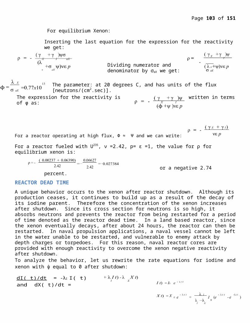
Page 103 of 107
Nuclear Propulsion Application :
Nuclear power will be of immenese significiant in the ....... transport, which in all can absorb a high propulsion of the available ....... supply of essential power. Motor vechile for transporations use 25% energy resources.
For the movement the use of nuclear power is confired to military sphere. As mentioned earlier the American submarine Nautical l......... put into comissin on 10 January 1955. Till its refelling in 1957 it had sailed 50,000 miles, much of ......... submerged and performance included an unbroken cru ise of 66 consequutive days.
Nauticle had demonstrated the ...........of nuclear powered marine engineer. Thus nuclear of ............. followed suit such as NS Soerannah , Ice broker ..... ......... carbon Ottohanm. If the use of nuclear of fission to power marine engines becoem generalise this will mean a complete reduction in navigation for ships will be able on a very s mall gravity of nuclear fuel to travel thus miles at more then present day running speeds, without intermidiate ........
There are two factors which still ......... generalisation of nuclear porpulsion.
a) The difficulty of ............... protection against dangerous radioactivity :- Now mostly solved as explained in follwoing section.
b) The high cost of nuclear reactor :- Once the proble of safety in solved, there should b e no furthere obstracles to the commercial application of nuclear propulsion. Considering the great advantage that this system of propulsions offer for merchant shipping . It will give high speed for any small consumption of nuclear fuel. Banker space will be free for the cargo to be caried. The duration of voyages will be shortened resulting in faster turn around. Even the small ............ of nuclear fuel will require replacement after a long time and the cost of operating the nuclear reactor will be very slow. These advantage are greatly offer to buy the high initial cost of the reactor. In that note cost of present day diesel engine is also not very ............ As more development in reactor metrial taken place and mass ...................of reactor start it will reduce the cose of the reactor to less than diesel engine. Thus ULCC class tanker, very cargo container carrier and VLBC ships are suitable for the marine propulsion reactor market.
Reactor Shielding Requirements :
In principle the problem of shielding the reactor itself involves theree aspects:
1) Slowing down fast neutrons.
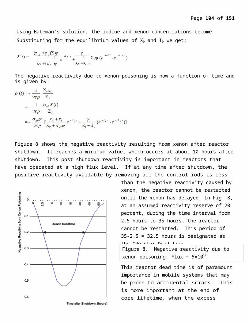
Page 104 of 107
2) Capture slowed neutorns .3) Alternation of all form of gama radiation. From reactor core and secondary radiation from the
interaction betweens the neutorns and nuclei in the shield.
Reactor shielding involves alternation of fast neutrons and gama radiations.
In a fast reactor the neutron flux escaping the reactor in quite huge and the breeder blanket of a fast reaction can be major source of radiation., as a result of fast fission on ( n, r) reaction with U-238.
Essentially all the energy absorbed in the shield from the fast neutron and gama rays is ultimately graded into .......... That means for a reactor of modrate or high power a considerable amount heat is generated within this shield –iones the absorption of both neutorns and gama radiations is experimental in character , a large proportion of the total heat liberated will be in the parts of the shield closed to heat of the reactor. In some power reactor ............. by coolant and hence it also contributes to the available energy.
To protect the shield fromt he possible damage from the heat liberated from upon absorbtion of radiation, a so called Thermal Shield is normally introduced close to the reactor. It is made of substouted thickness of ........ metal of fairly high melting point such as iron plaed .......... the reactor and the mainshield. This is some time also reffered to as the .............. shield.
The coolent flow in between the annular placess between the core, the inner thermal shield , and between the thermal shield and outer shield and between the outer shield and contain pressrue
Element such as Cadinium and contain Boron are also used with steel shield , toward the faceing the reactor. Because their high density lead and lead based alloys also bave been used in some extent in nuclear reactor shields. The mass ................efficiency of the lead better than iron but due to its lower melting point it can only be used in ............. of low temperature such as outside the pressured vessel. Tantalum and Tungston is ................. as both have high density and high melting point and are valuable as shields least expensive.
Refelling a submarine nuclear reactor.:
The removal of spent nuclear fuel is initiated about 20 days after the shut down druing which the reactors are allowed to cool. The process of measuring fuel takes about one months. The steps involved in charging the fuel in reactor includes
a) ........ away the segment of hull .............. the reactor.b) Taking steps to present the radioactive dusts. c) Disconnecting the primary cooling circuit
Page 105 of 107
d) Removing the fuel assemblies one by one using service ship ..........e) Storing the fuel assemblies in the metal container and lifting them onto the service ship
holds. f) Overhauling and rapairing reactor following removal of fuel assembles. g) Installing new fuel assemblies and taking new injecting, new coolant into the primary
circuit. h) Fastering the reactor lid and welding the portion of the hull that was removed.
Refiling process generates radioactive wastes in additon to ............. nuclear fuel . The refueling process about 10 cub meter of high level readioactive waste . Solid waste is generated from control rod reactor tank failings and contain...... equipment. The instalation of ............. filters ........... about one cubic meter of highly radioactive ion exchange sorbent and two to three
cubic meter of highly radioactive wasts. A regular refueling process generates from 155 ˜ 200m3 of radioactive wast.
Fast Breador Reactors in USE in Nuclear Submarines.:-
Sodium Colled Fast Reactors - The sodium cooled fast breader reactos is a generation IV reactor project is design on advanced. Fasst neutrons reactor it ............. on slowely related exesting integrated project, the LMFBR and the integral fast reactors with and objective of producing a fast spectrum , sodium cooled reactor and a closed fuel cycly for efficient management of actimides and can .................. U-238.
The fuel cycle involves a full actimide recycle with two major option.
1) One is an intermediate size ( 150 600 M We ) sodium cooled reator with Uranium Plutonium ............. actimide –Zireonium metal alloy fuel supported by fuel cycle based on pyromettalurgical reprocessing in facilities integrated wiht the reactor.
2) The second is the large (500 1500M We) sodium cooled with mixed uranium plutonium oxide fuel, supported by a full cycle based on advanced aqueous processing at a central location during a number of reactors. The outer temperature is generally 510 660 degrees celcius.
Operating temperature should not exceed the melting temperature of the fuel. Fuel to .................chemical interaction ( FCCI) has to be design against. ( FCCI ) FCCI is the ...... melting point between the fuel and the cladding, uranium, plutonium , latnaum ( ie. Fission product) inter diffuse with the iorn of the cladding to reduce in streng...... and could acutally .................... A design tank around has been proposed to have an inert matrix, magnesium ............. has an entire order of magnitude of smaller pro............. of interacting with nutrons than its element like iron.
Page 106 of 107
The SFR is designed for mamagement of high level waste and in particular, management of plutonium and actinides. Important safety feature of the system including a long thermal, response time, a large margine to coolant boiling, a primary system that operates near atmospheric pressure, and intermediate sodium preferably mercury, lead) system between radioactive sodium in the priamy system and water / steam . with invoation to reduce capital cost, such as making modular design removing a priamary look, integriating the pump and intermediate heat exchanger or simply finding better material for construction, the SFR can be viable technology or electric generation. The SFR’ passed spectrom also make a possible to use availabel fissile and fertile material ( including deepleted uranium ) considerably more efficently than thermal spectrum reactor with one through fuel cycle.
Lead Cooled Fast Reactor :
Lead cooled fast reactor is neuclear power generation IV reactor that features are past neutron spectrom and molten lead or lead-bismath eutectic coolent under closed fuel cycle obstions include a range of plant ratings including a number of 52-1050 MWe ( Mega Watt Electric ) units featuring long life premanufacturing core , modular arramgment 300-400 mg,. Watt and lareg monelith plant 1200 meg watt the fuel is metal nintrite base containg fertile uranium and transuranic . LFR is cooled by natural conventin with reactor outlet temepetaute of 550.C possibly ranging over 800.C withe advanced material. Tempertura higher than 830.C are high enough to support thermo chemical production of hydrogen.
Modular Neuclar Reactor :-
The LFR is small modular power plant using the cassett running on closed fuel cycle withe 50 20year refueling intervels or entirly repalcebel reactor modual. This is very suitable for country without suitable nuclear infrastructure.
The advantage of such design are:-
1. Instead of refueling, of whole core can be replaced after many year of operation. Life without refueling can be increas more easly in part due to efficiency.
2. No electricty is required for cooling after shut down. This design is safer than water cooled reactor like the one used in Fukushima.
3. Liquid based lead bismath system cant cost an explosion and equily soldify in case of leak, further improving safety.
4. This reactor shall lighter and smaller than water cooled reactor.
Disadvantage are as follow:-
Solidification of lead bismath turns the reacator in operable. However, the lead bismath uetetic has very low melting point tempeture of 123.C making this solidification and easty task.
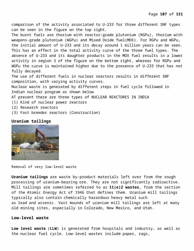
Page 107 of 107
This design was used in Sovit Alfa Class Submarine in 1970s as OK -550 BM-40A design both capable of producing 155 MWt they were significan tly liter than typical water cooled reactor and had advantage of quickly switching between maximum power and minumum noise, operation, but lack realibilty , The recent SVBR-100 lead bismath fast reactor is based on Alfa designs and have gross thermal power capacity of 280MWe. The coolent tempreture increases from 345.C to 495.C as it passes through core. Uranium oxide enriched to 16.5 % U-235 to be used as fuel core with core life of 7 to 8 years. Another varient uses uranium nintrate incase in HT-9 cubes using a quartz reflector.