Embed Size (px)
Citation preview
1
Nuclear Power Plant Gaseous Waste Treatment System Design
Siegfried L. Stockinger, P.E.
INTRODUCTION
Nuclear power reactors generate radioactive fission products during their operation, among them are xenon and krypton gases. Some of these will be released to the coolant when there are fuel cladding defects. Because the gases are not completely soluble within the coolant, they are available for release to the environs. To limit the radiation exposure to the public, off-gas treatment systems for removing these volatile fission products are installed at nuclear power plants.
TABLE of CONTENTS 1.0 OVERVIEW 2
1.1 Source Terms 2-5 1.2 Other releases 5 1.3 Noble Gases Xenon/Krypton 5-8 1.4 Charcoal Delay 9 1.5 Dynamic Adsorption 9-10
2.0 BWR SYSTEM DESCRIPTION 11 2.1 Hydrogen-Oxygen Recombination 11
2.2 Design Gas Flow 12 2.3 Steam Jet Air Ejector & Recombination 12-17 2.4 Hydrogen Detonation 17-20 2.5 Condensate Drainage 21 2.6 Moisture Removal 21-23
3.0 CHARCOAL DELAY 23-25 4.0 COMPRESSED GAS STORAGE 25-26 5.0 CRYOGENIC DISTILLATION 26-29 6.0 REDUNDANCY and INSTRUMENTATION 29-30 7.0 PWR SYSTEM DESCRIPTIONS 31 7.1 Design Gas Flow 31-32 7.2 Waste Gas Decay Tanks 32-33 7.3 Ambient Charcoal 33-34 7.4 Nitrogen Recycle 34-35 7.5 Cryogenic Charcoal 35-36 8.0 DESIGN CODES 37 9.0 SYSTEM LAYOUT/ARRANGEMENT AND SHIEDING _38-40 10.0 TROUBLES TO AVOID WITH OFF-GAS SYSTEMS 41-43 11.0 ACTIVATED CHARCOAL SELECTION & PLANNING 44-51 12.0 REFERERENCES______________________________52-54
Prepared for the American Society of Mechanical Engineers - Radioactive Waste Systems Committee -- Copyright 2012

2
1.0 OVERVIEW
1.1 Source Terms
Xenon and Krypton are the primary source term isotopes that remain available for release to the environment. Time will decay activity of both as seen in the curves below, with Xenon’s activity being greater and needing a greater length of time.
Activity releases will occur from several points. Since the gases are dissolved in the coolant they are transported to various systems in the plant as a result of leakage and process transfers. Releases to the atmosphere will occur when the coolant from the various systems leaks in the building and evolved gases are carried out by the ventilation systems. The release points and
Prepared for the American Society of Mechanical Engineers - Radioactive Waste Systems Committee -- Copyright 2012
3
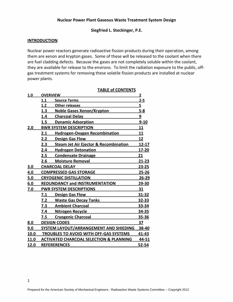
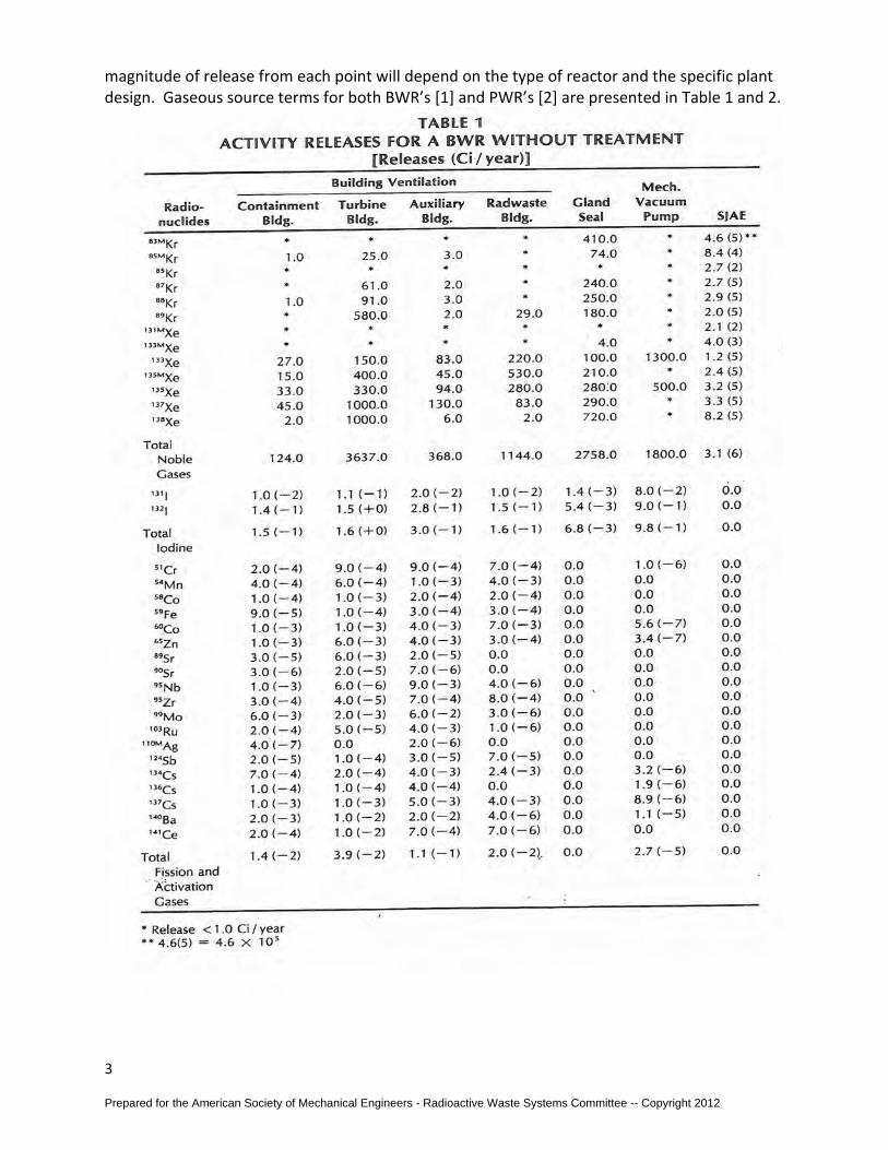
magnitude of release from each point will depend on the type of reactor and the specific plant design. Gaseous source terms for both BWR’s [1] and PWR’s [2] are presented in Table 1 and 2.
Prepared for the American Society of Mechanical Engineers - Radioactive Waste Systems Committee -- Copyright 2012
4
As can be seen from the data presented in Tables 1 and 2 the dominant source of activity release from a BWR is the steam jet air ejector (SJAE) which removes the non condensable gases from the main steam in the condenser (while pulling a vacuum on the condenser to improve cooling/condensation). Activity releases from a PWR are dominated by the gas stripper. In both cases the isotopes released are essentially all noble gases. Due to the magnitude of these sources it is necessary to provide a system to remove the radioactive gases.
This tutorial concentrates on the treatment of gases from the SJAE of a BWR and the gas stripper of a PWR, since these are the major sources of gaseous releases from these plants and
Prepared for the American Society of Mechanical Engineers - Radioactive Waste Systems Committee -- Copyright 2012
5
the systems needed to treat the gases are complex. After the installation of treatment equipment the gases released from these streams represent only a small fraction of the total plant radioactive release.
1.2 Other releases
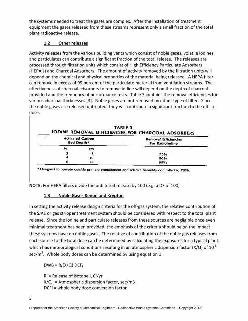
Activity releases from the various building vents which consist of noble gases, volatile iodines and particulates can contribute a significant fraction of the total release. The releases are processed through filtration units which consist of High Efficiency Particulate Adsorbers (HEPA’s) and Charcoal Adsorbers. The amount of activity removed by the filtration units will depend on the chemical and physical properties of the material being released. A HEPA filter can remove in excess of 99 percent of the particulate material from ventilation streams. The effectiveness of charcoal adsorbers to remove iodine will depend on the depth of charcoal provided and the frequency of performance tests. Table 3 contains the removal efficiencies for various charcoal thicknesses [3]. Noble gases are not removed by either type of filter. Since the noble gases are released untreated, they will contribute a significant fraction to the offsite dose.
NOTE: For HEPA filters divide the unfiltered release by 100 (e.g. a DF of 100)
1.3 Noble Gases Xenon and Krypton
In setting the activity release design criteria for the off-gas system, the relative contribution of the SJAE or gas stripper treatment system should be considered with respect to the total plant release. Since the iodine and particulate releases from these sources are negligible once even minimal treatment has been provided, the emphasis of the criteria should be on the impact these systems have on noble gases. The relative of contribution of the noble gas releases from each source to the total dose can be determined by calculating the exposures for a typical plant which has meteorological conditions resulting in an atmospheric dispersion factor (X/Q) of 10-6
sec/m3. Whole body doses can be determined by using equation 1.
DWB = Ri (X/Q) DCFi
Ri = Release of isotope i, Ci/yr X/Q = Atmospheric dispersion factor, sec/m3 DCFi = whole body dose conversion factor
Prepared for the American Society of Mechanical Engineers - Radioactive Waste Systems Committee -- Copyright 2012
6
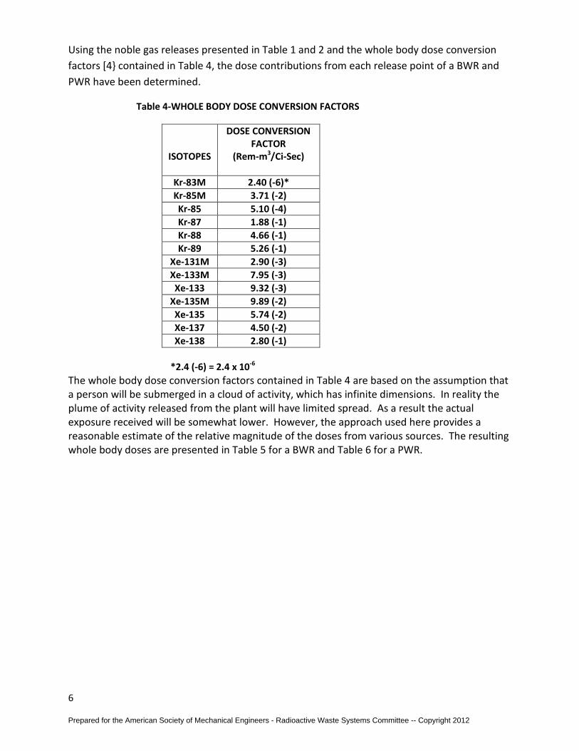
Using the noble gas releases presented in Table 1 and 2 and the whole body dose conversion factors [4} contained in Table 4, the dose contributions from each release point of a BWR and PWR have been determined.
Table 4-WHOLE BODY DOSE CONVERSION FACTORS
ISOTOPES
DOSE CONVERSION FACTOR
(Rem-m3/Ci-Sec)
Kr-83M 2.40 (-6)* Kr-85M 3.71 (-2) Kr-85 5.10 (-4) Kr-87 1.88 (-1) Kr-88 4.66 (-1) Kr-89 5.26 (-1)
Xe-131M 2.90 (-3) Xe-133M 7.95 (-3) Xe-133 9.32 (-3)
Xe-135M 9.89 (-2) Xe-135 5.74 (-2) Xe-137 4.50 (-2) Xe-138 2.80 (-1)
*2.4 (-6) = 2.4 x 10⁻⁶ The whole body dose conversion factors contained in Table 4 are based on the assumption that a person will be submerged in a cloud of activity, which has infinite dimensions. In reality the plume of activity released from the plant will have limited spread. As a result the actual exposure received will be somewhat lower. However, the approach used here provides a reasonable estimate of the relative magnitude of the doses from various sources. The resulting whole body doses are presented in Table 5 for a BWR and Table 6 for a PWR.
Prepared for the American Society of Mechanical Engineers - Radioactive Waste Systems Committee -- Copyright 2012
7
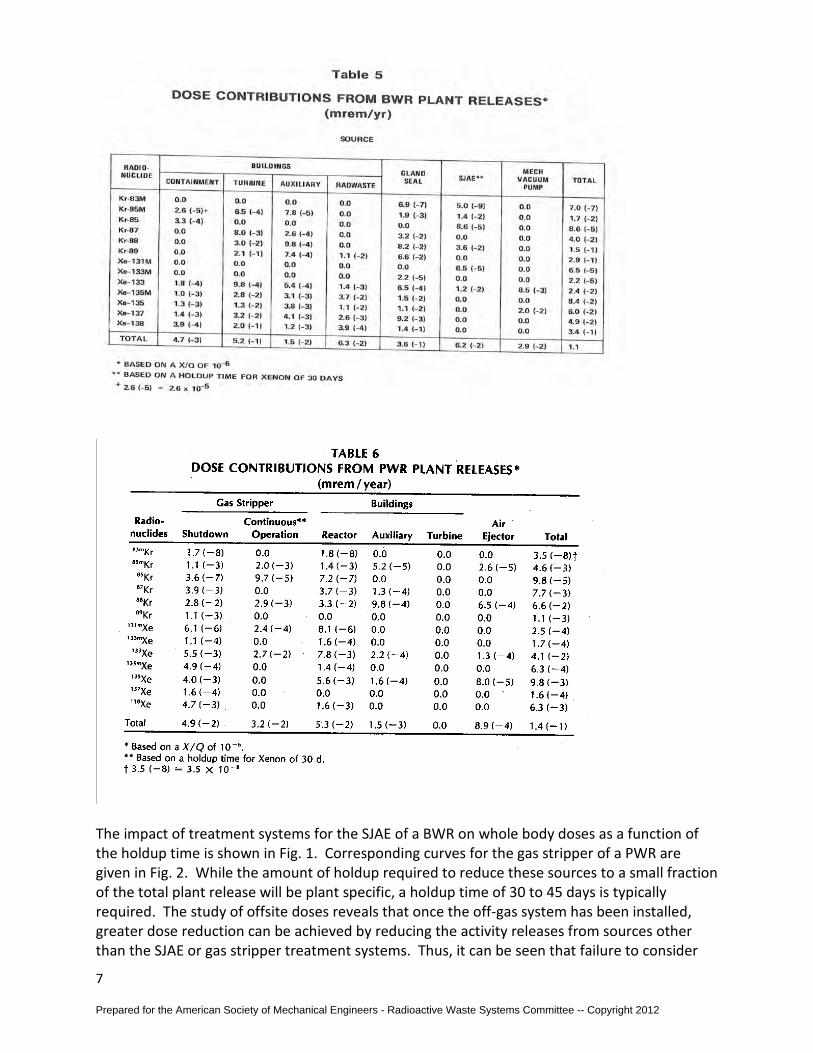
The impact of treatment systems for the SJAE of a BWR on whole body doses as a function of the holdup time is shown in Fig. 1. Corresponding curves for the gas stripper of a PWR are given in Fig. 2. While the amount of holdup required to reduce these sources to a small fraction of the total plant release will be plant specific, a holdup time of 30 to 45 days is typically required. The study of offsite doses reveals that once the off-gas system has been installed, greater dose reduction can be achieved by reducing the activity releases from sources other than the SJAE or gas stripper treatment systems. Thus, it can be seen that failure to consider
Prepared for the American Society of Mechanical Engineers - Radioactive Waste Systems Committee -- Copyright 2012

8
activity releases from other sources when setting the design activity release from these off-gas treatment systems can result in excessive designs.
Prepared for the American Society of Mechanical Engineers - Radioactive Waste Systems Committee -- Copyright 2012

9
1.4 Charcoal Delay Beds
The large volume of process gas with its associated treatment system, plus the high building cost involved when the entire air leakage flow is stored long enough to achieve the required decay, suggested that the means for removing krypton and xenon from the air stream needed investigation. Experimental data indicated that charcoal could be used since it exhibits a dynamic adsorption of both these noble gases from air. The required holdup time (i.e., removal efficiency) of a charcoal bed is function of the gas flow rate, mass of charcoal, and dynamic adsorption coefficient, K. The value of K, in turn, depends on the concentration of fission gases, system operating pressure, system operating temperature, and moisture content of the charcoal. An equation [19 &20] for the charcoal holdup time is given below:
T = 0.53 MK/F Where
T = holdup time in hours, M= mass of charcoal adsorber in tons (2,000 lbs.) K = dynamic adsorption coefficient in cm3/g, and F= gas flow rate in scfm.
1.5 Dynamic Adsorption: • The adherence of molecules of a gas (fission product noble gases) onto the surface of a
solid (activated charcoal) • Adsorption is reversible (desorption) • Rates of adsorption and desorption vary with each gas species.
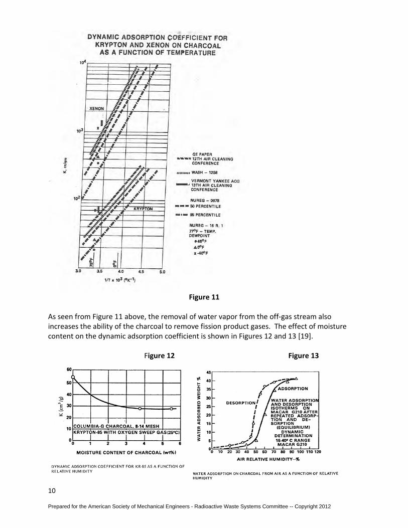
Dynamic adsorption coefficients bases on laboratory test and operating performance are shown in Fig. 11 [1, 19, 20, 22, and 23]. As seen in Fig. 11, the dynamic adsorption coefficient is a strong function of temperature. Decreasing the operating temperature increases the adsorption coefficient, thus decreasing the volume of charcoal required to achieve a given holdup time. Based on the data in Fig. 11, reduction of the bed temperature from ambient to -18oC (0oF), increases the adsorption coefficient by a factor of three and thus reduces the required charcoal volume by the same factor. Charcoal adsorption systems have different holdup times for krypton and xenon since the dynamic adsorption coefficient for xenon is approximately 18 times higher than that for krypton [1, 20, 21, and 23]. For a fixed quantity of charcoal, the xenon holdup time is therefore 18 times longer for krypton. Fortunately, except for Kr-85, the charcoal delay system which provides a satisfactory xenon dose reduction will also supply a similar dose reduction for krypton.
Prepared for the American Society of Mechanical Engineers - Radioactive Waste Systems Committee -- Copyright 2012
10
Figure 11
As seen from Figure 11 above, the removal of water vapor from the off-gas stream also increases the ability of the charcoal to remove fission product gases. The effect of moisture content on the dynamic adsorption coefficient is shown in Figures 12 and 13 [19]. Figure 12 Figure 13
Prepared for the American Society of Mechanical Engineers - Radioactive Waste Systems Committee -- Copyright 2012
11
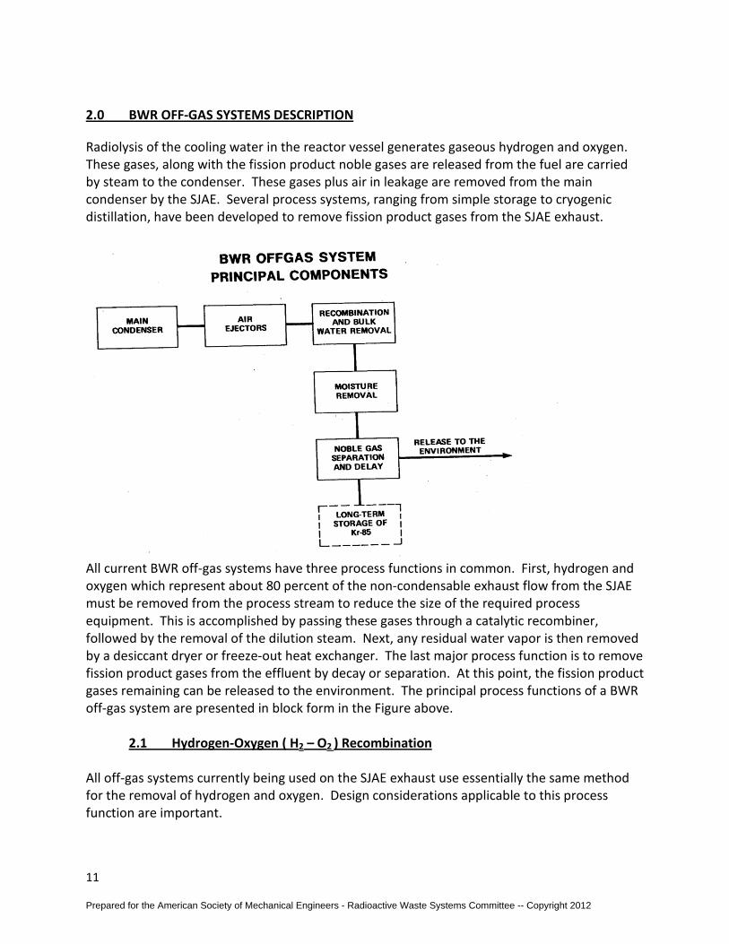
2.0 BWR OFF-GAS SYSTEMS DESCRIPTION
Radiolysis of the cooling water in the reactor vessel generates gaseous hydrogen and oxygen. These gases, along with the fission product noble gases are released from the fuel are carried by steam to the condenser. These gases plus air in leakage are removed from the main condenser by the SJAE. Several process systems, ranging from simple storage to cryogenic distillation, have been developed to remove fission product gases from the SJAE exhaust.
All current BWR off-gas systems have three process functions in common. First, hydrogen and oxygen which represent about 80 percent of the non-condensable exhaust flow from the SJAE must be removed from the process stream to reduce the size of the required process equipment. This is accomplished by passing these gases through a catalytic recombiner, followed by the removal of the dilution steam. Next, any residual water vapor is then removed by a desiccant dryer or freeze-out heat exchanger. The last major process function is to remove fission product gases from the effluent by decay or separation. At this point, the fission product gases remaining can be released to the environment. The principal process functions of a BWR off-gas system are presented in block form in the Figure above.
2.1 Hydrogen-Oxygen ( H2 – O2 ) Recombination All off-gas systems currently being used on the SJAE exhaust use essentially the same method for the removal of hydrogen and oxygen. Design considerations applicable to this process function are important.
Prepared for the American Society of Mechanical Engineers - Radioactive Waste Systems Committee -- Copyright 2012
12
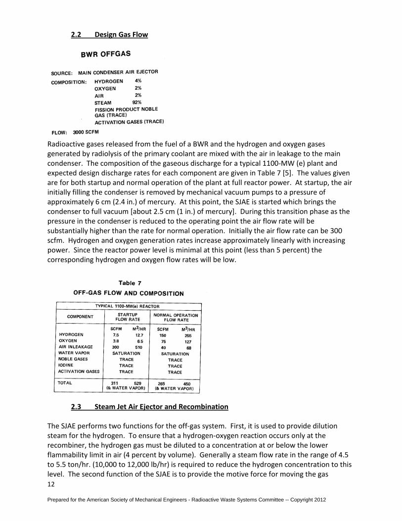
2.2 Design Gas Flow
Radioactive gases released from the fuel of a BWR and the hydrogen and oxygen gases generated by radiolysis of the primary coolant are mixed with the air in leakage to the main condenser. The composition of the gaseous discharge for a typical 1100-MW (e) plant and expected design discharge rates for each component are given in Table 7 [5]. The values given are for both startup and normal operation of the plant at full reactor power. At startup, the air initially filling the condenser is removed by mechanical vacuum pumps to a pressure of approximately 6 cm (2.4 in.) of mercury. At this point, the SJAE is started which brings the condenser to full vacuum [about 2.5 cm (1 in.) of mercury]. During this transition phase as the pressure in the condenser is reduced to the operating point the air flow rate will be substantially higher than the rate for normal operation. Initially the air flow rate can be 300 scfm. Hydrogen and oxygen generation rates increase approximately linearly with increasing power. Since the reactor power level is minimal at this point (less than 5 percent) the corresponding hydrogen and oxygen flow rates will be low.
2.3 Steam Jet Air Ejector and Recombination
The SJAE performs two functions for the off-gas system. First, it is used to provide dilution steam for the hydrogen. To ensure that a hydrogen-oxygen reaction occurs only at the recombiner, the hydrogen gas must be diluted to a concentration at or below the lower flammability limit in air (4 percent by volume). Generally a steam flow rate in the range of 4.5 to 5.5 ton/hr. (10,000 to 12,000 lb/hr) is required to reduce the hydrogen concentration to this level. The second function of the SJAE is to provide the motive force for moving the gas
Prepared for the American Society of Mechanical Engineers - Radioactive Waste Systems Committee -- Copyright 2012
13
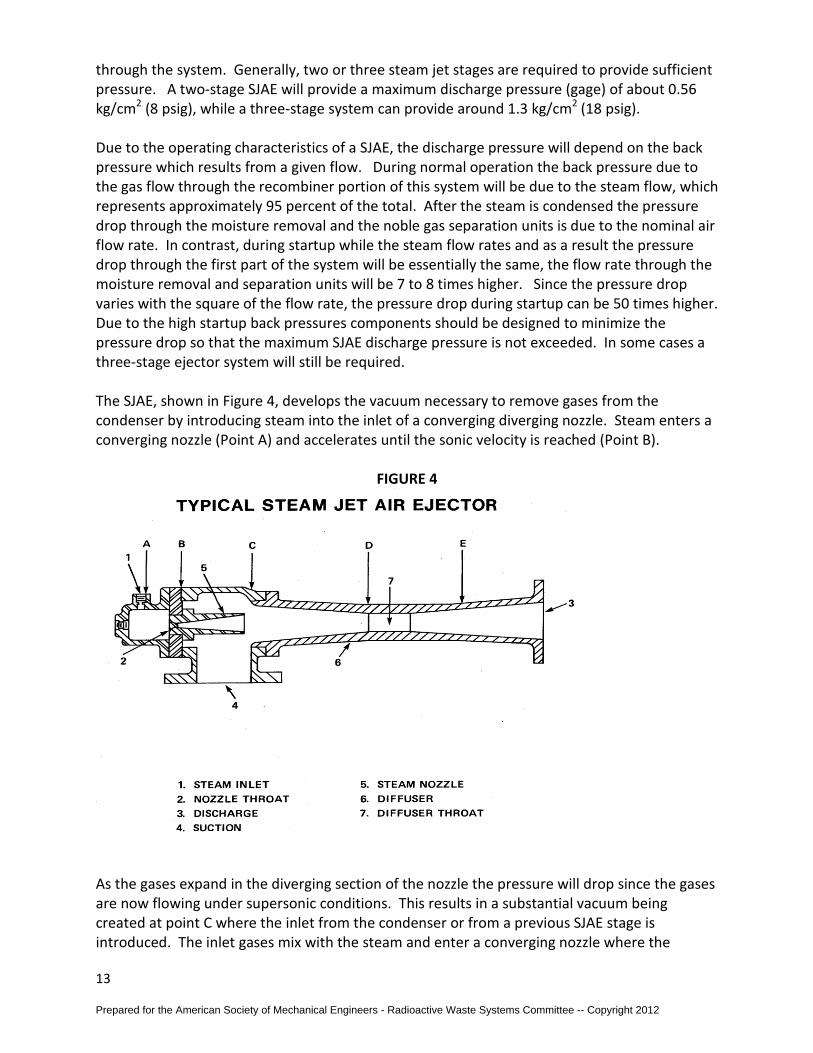
through the system. Generally, two or three steam jet stages are required to provide sufficient pressure. A two-stage SJAE will provide a maximum discharge pressure (gage) of about 0.56 kg/cm2 (8 psig), while a three-stage system can provide around 1.3 kg/cm2 (18 psig). Due to the operating characteristics of a SJAE, the discharge pressure will depend on the back pressure which results from a given flow. During normal operation the back pressure due to the gas flow through the recombiner portion of this system will be due to the steam flow, which represents approximately 95 percent of the total. After the steam is condensed the pressure drop through the moisture removal and the noble gas separation units is due to the nominal air flow rate. In contrast, during startup while the steam flow rates and as a result the pressure drop through the first part of the system will be essentially the same, the flow rate through the moisture removal and separation units will be 7 to 8 times higher. Since the pressure drop varies with the square of the flow rate, the pressure drop during startup can be 50 times higher. Due to the high startup back pressures components should be designed to minimize the pressure drop so that the maximum SJAE discharge pressure is not exceeded. In some cases a three-stage ejector system will still be required. The SJAE, shown in Figure 4, develops the vacuum necessary to remove gases from the condenser by introducing steam into the inlet of a converging diverging nozzle. Steam enters a converging nozzle (Point A) and accelerates until the sonic velocity is reached (Point B).
FIGURE 4
As the gases expand in the diverging section of the nozzle the pressure will drop since the gases are now flowing under supersonic conditions. This results in a substantial vacuum being created at point C where the inlet from the condenser or from a previous SJAE stage is introduced. The inlet gases mix with the steam and enter a converging nozzle where the
Prepared for the American Society of Mechanical Engineers - Radioactive Waste Systems Committee -- Copyright 2012
14
velocity is reduced to near sonic conditions (Point D). After the gases exit the second nozzle the pressure of the gases will increase until it equals the back pressure developed by the flow rate of gases through the downstream components. If the back pressure increases, the final transition shock wave will move back up into the nozzle. If the discharge pressure increases to the point where the shock wave moves back up into the nozzle, the transition into supersonic flow will not occur. As a result a vacuum cannot be created. When this occurs, the suction capability of the SJAE is lost. Since gases will continue to enter the condenser the pressure will increase to the point where the reactor must shut down. A two-stage jet requires less steam than a three-stage jet. However, the steam flow to the second stage, necessary for sustaining the desired discharge pressure, is generally in excess of that required to reduce the hydrogen concentration in the off-gas air to below 4 percent by volume. This excess steam flow requires an increase in the size of the components used to recombine hydrogen and oxygen. The number of stages finally incorporated into the system depends on the relative costs of steam and process equipment, system back pressure, SJAE operating characteristics. If flow through the SJAE is temporarily lost while the reactor is still operating at full power, hydrogen and oxygen will build up in the main condenser until either the condenser pressure has reached the high pressure trip setting or normal action is taken to initiate a reactor shutdown. Then, upon restart of the off-gas system, the flow of hydrogen and oxygen will be greater than under normal conditions and a greater than usual temperature increase through the recombiner will result. Excessive temperature in the recombiner can be avoided by using the temperature-sensing elements at the recombiner to initiate a reduction in the off-gas flow rate. This can best be accomplished by throttling the flow from the condenser to the SJAE, although this will increase the time required for plant startup. To reduce the steam requirements for dilution of the off-gas from the SJAE, several systems have incorporated an air recycle line. The bulk of the air from the off-gas condenser is returned to the inlet of the jet compressor. A small portion of the air equal to the main condenser air in leakage is discharged into the downstream portion of the system. With an air recycle system, the stream flow rates at the design conditions can be reduced by 50 percent, i.e., to 2.2 to 2.7 ton/hr (5,000 to 6,000 lb/hr). The savings in steam, however, must be balanced against the larger capital costs associated with larger components. In an air recycle system, air is removed from the recycle loop at the same rate that it enters. An imbalance in the air flow causes a pressure transient which could temporarily interrupt the operation of the system. The catalytic material used in the recombiner of an air recycle system should not be subject to dusting since experience has shown that the dust will be transported upstream of the recombiner where it can plate out and can cause hydrogen detonation problems. For a system which does not have additional pumps in the process stream beyond the jet compressors, the excess flow at startup can be managed by reducing the pressure drop through system. The shutdown head of the jet compressor will then not be exceeded under maximum air flow conditions. Although this approach is readily applicable to charcoal delay systems which have a small/low operating pressure, several systems, including cryogenic distillation, are designed for a fixed air flow rate which is equal to the design air inleakage rate at full power
Prepared for the American Society of Mechanical Engineers - Radioactive Waste Systems Committee -- Copyright 2012
15
operation. These systems have, at the off-gas condenser discharge, an additional mechanical compressor which has different flow characteristics from that of the jet compressor. If excess air is not controlled during startup, the jet compressor will out-pump the mechanical compressor thus resulting in a pressure buildup between them until the shutoff head of the jet compressor is reached. Over-pressurization of the system during startup can be prevented by reducing the flow rate to the SJAE or by recycling gas from downstream of the off-gas condenser back to the main condenser. Both of these alternatives have the disadvantage of increasing the time required to bring the plant on line. The second alternative, however, will also allow for removal of any hydrogen and oxygen that is generated during reactor startup. Recombination of hydrogen and oxygen is achieved by using a platinum/palladium-type catalyst with either a metallic or ceramic base. Hydrogen in the off-gas air is diluted to keep its concentration below the 4 percent by volume (lower flammability level) and to prevent excessive post-reaction temperature from occurring within the recombiner. Since recombiner performance is adversely affected by moisture, a preheater upstream of the recombiner is used to dry the influent gas by raising the temperature to approximately 190oC (380oF). The typical performance curve for a BWR off-gas system recombiner, given in Fig. 5 [6], shows that the hydrogen effluent concentration decreases as the inlet temperature is increased. Recombiner performance also depends on the inlet hydrogen concentration and the air inleakage. At inlet gas concentration of about 2 percent hydrogen by volume, the effluent concentration drops sharply to nearly zero and remains at this low level out beyond the design inlet concentration of 4 percent hydrogen by volume. The completeness of the recombination reaction will depend on the amount of excess oxygen present. On a BWR system, air inleakage to the main condenser is the only source of excess oxygen; hence, if air inleakage is small, the size of the recombiner catalyst bed will have to be increased to make up for the loss of efficiency at the low air flow rates. To compensate for low air inleakage rates, some off-gas systems have incorporated an air supply of about 0.17 m3/min at standard temperature and pressure (STP), or 6 scfm, from the instrument air system. Energy given off by the reaction of hydrogen and oxygen will result in a temperature rise of 70oC (125oF) for every percent of hydrogen in the influent gas. For a design hydrogen concentration of 4 percent by volume and an influent temperature of 190oC (380oF), the effluent temperature will be approximately 470oC (880oF). In a BWR system, the gas at the outlet of the recombiner will be essentially all steam, consisting of the inlet steam plus the water vapor resulting from the recombination of hydrogen and oxygen. At typical system operating gage pressure of 0.35 kg/cm2 (5 psig), the gas will be 315oC (600oF) super heated. The off-gas condenser must be capable of desuperheating and condensing the steam mixture, subcooling the condensate, and cooling the air discharge. Cooling water for the off-gas condenser should be low in dissolved solids to prevent deposit buildup in the off-gas condenser desuperheating tubes. Since the steam flow rate is typically about 5.5 ton/hr [12,000 lb/hr (24 gpm)], this source can represent a major contribution to the Radwaste system. Condensate which includes the dilution steam and the water formed by recombination of hydrogen and oxygen is routed back to the main condenser to maintain the primary coolant water inventory, reduce the flow to the radwaste system, and reduce the potential for accidental releases from drain valves which may become stuck in an open position.
Prepared for the American Society of Mechanical Engineers - Radioactive Waste Systems Committee -- Copyright 2012

16
A typical flow diagram for the hydrogen-oxygen recombination section of a BWR off-gas system is shown in Fig. 6 [7]. Gas flow rates, temperatures, and pressures which correspond to a typical system with a 12,000 lb/hr steam dilution flow are presented in Table 8. The flow points given in Table 8 correspond to those shown in Figure 6.
FIGURE 6
Prepared for the American Society of Mechanical Engineers - Radioactive Waste Systems Committee -- Copyright 2012

17
TABLE 8
2.4 Hydrogen Detonation
Hydrogen and oxygen generated in the reactor core by radiolysis of the cooling water will be removed from the primary coolant by the off-gas treatment system. Because of the explosive nature of these gases, their presence in the system must be considered in the design phase. The potential hazards associated with processing hydrogen and oxygen can be reduced or eliminated by diluting the off-gas stream so that the hydrogen concentrations are kept below the explosive limit, eliminating ignition sources, and by designing the system with the capability to contain an explosion should one occur.
Prepared for the American Society of Mechanical Engineers - Radioactive Waste Systems Committee -- Copyright 2012
18
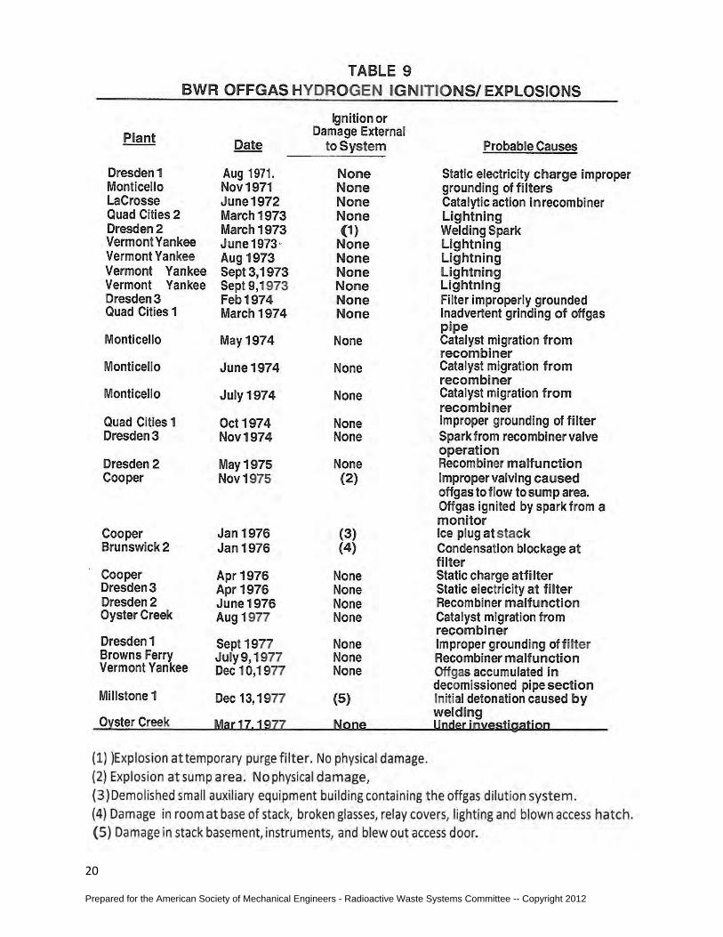
To prevent high hydrogen concentrations from occurring in the system downstream of the recombiner, the outlet hydrogen concentration is monitored downstream of the off-gas condenser, after the dilution steam has been removed. In the event of a recombiner failure, high hydrogen concentrations will be detected and an alarm will be triggered. The alarm signal can be used to initiate a system shutdown to prevent an unsafe condition. An additional safety feature that can be incorporated into the system is instrumentation that can detect, alarm, and initiate shutdown upon loss of steam dilution flow. Operating experience with BWR off-gas systems indicates that several hydrogen explosions have occurred during their operation and maintenance [8]. A list of the hydrogen explosions which have occurred is presented in Table 9. The causes of the explosions have been traced to many sources, including:
1. Spark from ungrounded metal parts, 2. Sparks from rapid valve closure, 3. Catalyst fines which have migrated to areas of high hydrogen concentration, and 4. Release of gas into the structures housing the system.
Although it is not possible to anticipate all the possible causes, the probability of an explosion can be substantially reduced by proper design considerations, such as the use of nonsparking materials in valves and the grounding of all internal metal parts including filter supports. A number of plants that have experienced hydrogen explosions have subsequently found catalyst dust and small pieces from the recombiner catalyst on the inside surface of pipes upstream of the recombiner. The presence of catalyst dust in these areas has been attributed to improper hydrostatic testing procedures and carryovers by air recycle. Releases of the hydrogen gases into the room containing the off-gas system have resulted from improper purging of the system prior to maintenance and/or over pressurization of the system during operation with subsequent release of gas through a loop seal or rupture disk.
Prepared for the American Society of Mechanical Engineers - Radioactive Waste Systems Committee -- Copyright 2012
19
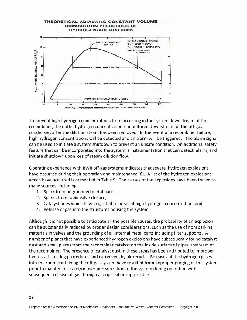
The probability of a hydrogen explosion can be reduced by certain design modifications. However, if a detonation wave occurs, the pressure pulse will be applied rapidly [the speed of the detonation wave will be approximately 3050 m/sec (10,000 ft/sec)] to the pipe wall for a duration which is small compared to the natural period oscillation for a pipe. Because, of this rapid propagation and the short duration of a detonation wave, the pipe will be stressed at the maximum level before a rupture disk, or relief valve, can effectively relieve the pressure. Therefore, off-gas systems should also be designed, to the maximum practical extent, to contain such an explosion should it occur. If hydrogen and oxygen do react, the degree and violence of the reaction will depend on the concentrations of hydrogen, oxygen, and water vapor in the mixture. The concentrations of hydrogen in the mixture will determine the rate and completeness of the reaction, with no reaction occurring at hydrogen concentration below 4 percent by volume in air. When the hydrogen concentration is between 4 percent and 8 percent by volume and an ignition source is present, hydrogen and oxygen will begin to burn. The burning will be limited to local flame pockets since the hydrogen concentration is not sufficient to maintain a continuous wave front [9]. In this concentration range, combustion will be incomplete and the resulting pressure rise will be negligible. However, when the hydrogen concentration exceeds approximately 8 percent, an explosive wave will develop with a pressure change proportional to the hydrogen concentration. When a hydrogen concentration of 17 percent by volume is reached, a full detonation will develop in the air mixture. The maximum pressure rise on detonation will depend on the presence of other gases and ratio of hydrogen to oxygen, with maximum pressure increase occurring from a stoichiometric hydrogen and oxygen mixture (i.e., 30 volume percent H2 in air). The presence of water vapor has a quenching effect which will reduce the maximum pressure attained [10]. The detonation pressure applied to the pressure boundary will be different for vessels and pipes owing to the form of the detonation wave [11]. The energy released by the detonation can result in a maximum pressure increase for vessels which will be a factor of about 17 above the initial pressure in the system [10, 11, and 12]. Experimental data have been reported which demonstrate that higher pressure increases will occur at bends in the pipe or at other obstructions to flow. The maximum pressure for elbows is a factor of about 2.5 above that for straight pipe [13 and 14]. Further pressure increases above these factors may be observed near the ignition point due to a nonconstant specific heat during the initial period of the reaction [15]. Pipe and vessel designs for containing hydrogen explosions should incorporate allowances for the above pressure increases. While the detonation can result in substantially higher pressures, there are additional considerations which should be considered in the design. These considerations include the use of dynamic load factors for sudden pressure pulses, and the increases in yield strength which occur at high strain rates [16 and 17].
Prepared for the American Society of Mechanical Engineers - Radioactive Waste Systems Committee -- Copyright 2012
20
Prepared for the American Society of Mechanical Engineers - Radioactive Waste Systems Committee -- Copyright 2012
21
2.5 Condensate Drainage Proper operation of the recombiner is based on maintenance of a dry gas mixture at the inlet. Normally this can be accomplished by the preheater. However, when the system is started from a cold shutdown, the steam which is used to heat the pipe will condense at an excessive rate until the pipe reaches its operating temperature. The drainage lines must be sized to handle the condensation rates during system startup. Also, since the high gas flow rates will cause the condensed water to move rapidly down the pipe, the water may completely bypass the drain and enter the downstream equipment if small drain lines are used. Therefore, the drains should be designed to collect water from a significantly larger area than the drain line itself. Another significant design consideration is the heat loss from the system before the gases reach the recombiner. As heat is lost through the insulation on the pipe, steam will begin to condense and form water droplets. Adequate moisture removal and drainage must provided upstream of the preheater to ensure proper operation. Since water droplet will still be entrained in the gas mixture, the system must be designed to remove water droplets from the gas. Their evaporation in the preheater is difficult because of the higher heat input rate required and the limited residence time. If these water droplets are not evaporated in the preheater then they can enter the recombiner and quench the catalyst, thus preventing complete recombination of the hydrogen and oxygen gases.
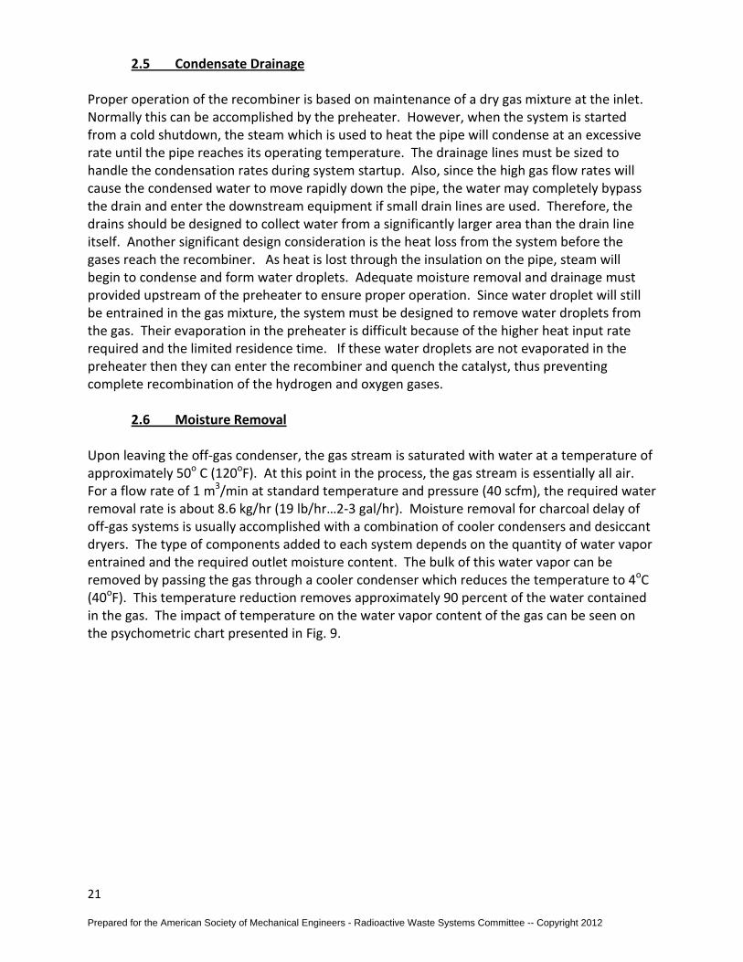
2.6 Moisture Removal Upon leaving the off-gas condenser, the gas stream is saturated with water at a temperature of approximately 50o C (120oF). At this point in the process, the gas stream is essentially all air. For a flow rate of 1 m3/min at standard temperature and pressure (40 scfm), the required water removal rate is about 8.6 kg/hr (19 lb/hr…2-3 gal/hr). Moisture removal for charcoal delay of off-gas systems is usually accomplished with a combination of cooler condensers and desiccant dryers. The type of components added to each system depends on the quantity of water vapor entrained and the required outlet moisture content. The bulk of this water vapor can be removed by passing the gas through a cooler condenser which reduces the temperature to 4oC (40oF). This temperature reduction removes approximately 90 percent of the water contained in the gas. The impact of temperature on the water vapor content of the gas can be seen on the psychometric chart presented in Fig. 9.
Prepared for the American Society of Mechanical Engineers - Radioactive Waste Systems Committee -- Copyright 2012
22
FIGURE 9
Further water removal can be accomplished by passing the gas through a desiccant dryer. By adsorption on a molecular sieve, the water content can be reduced so that the dew point of the effluent gas is -60oC (-80oF). The high gas flow rate coupled with the long decay time required for a BWR off-gas system generally requires a substantial amount of charcoal. As will be discussed in the following section, the mass of charcoal required can be reduced it the operating temperature and moisture content of the gas is decreased. Since a number of these systems operate at temperatures below 0oC (32oF), it is essential that all of the water be removed from the gas to prevent ice formation. A Molecular sieve bed will continue to remove water from the gas until the bed becomes saturated. When saturation occurs, flow is transferred to an alternate bed which is free of water. The saturated bed can be regenerated by heating the bed to evaporate the water which had been adsorbed. The regeneration loop consists of a blower, heater, and dryer chiller which condition the air before it is circulated through the saturated bed. Prior to entering the saturated desiccant bed, the air is heated to between 150o and 200o C (300o to 400oF) to affect water evaporation from the bed. Water-saturated air leaving the bed is passed through a chiller which removes water by condensation. Recirculation of the dried air is continued until the bed is returned to its initial dry condition. Water removed from the regeneration loop can be routed to either the main condenser or the liquid radwaste system. A typical flow diagram for the moisture removal subsystem using a closed-loop regeneration cycle is shown in Fig. 10.
Prepared for the American Society of Mechanical Engineers - Radioactive Waste Systems Committee -- Copyright 2012

23
Since the adsorption efficiency of the charcoal beds is adversely affected by water and chemical impurities, a number of systems incorporate a charcoal guard bed upstream of the charcoal absorbers. If a system malfunction results in excessive moisture or other gases, the guard bed will remove these contaminants before they reach the main delay beds. Since the guard bed has a volume of 0.06 to 0.08 m3 (2 to 3 ft3), it is more easily replaced than the charcoal in the large bed. As additional protection against a spike in the gas release rate or an excessive water flow to the first absorber bed, some systems are designed so that the first bed can be isolated and the off-gas flow directed to the second bed.
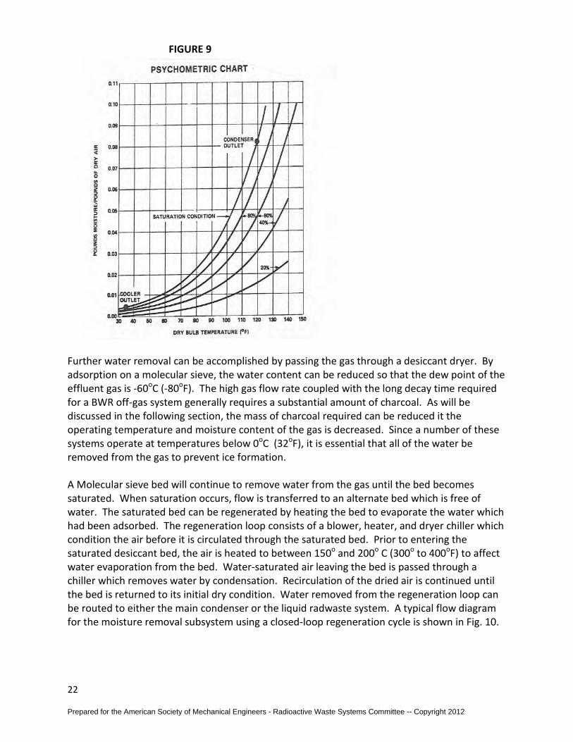
3.0 CHARCOAL DELAY The charcoal delay system utilizes the dynamic adsorption of krypton and xenon to remove these radioactive gases from the process off-gas prior to release. After leaving the recombiner portion of the system, the gas can either enter a 10-minute delay line to allow for decay of the short half-life fission products, or may, as an alternative, pass through a small charcoal bed which will hold the fission product gases long enough to remove those having short half lives. To increase the adsorption efficiency of the charcoal, any water vapor remaining with the gas is extracted by a moisture removal subsystem. The charcoal is contained in several tanks operated in series downstream of the moisture removal equipment. A schematic of the typical BWR ambient charcoal system is presented in Fig. 8.
Prepared for the American Society of Mechanical Engineers - Radioactive Waste Systems Committee -- Copyright 2012
24
A typical scheme for the refrigerated charcoal adsorption system is present in Fig. 14. Prior to entering the charcoal guard bed, the off-gas stream is processed through a desiccant dryer to remove water vapor which would otherwise freeze out in the -18oC (0oF) being maintained by a mechanical refrigeration unit which also cools the influent gas stream. The cooled gas then enters the charcoal beds where krypton and xenon are removed prior to discharge. Off-site dose reduction factors for a refrigerated charcoal system can be increased as necessary by adding more charcoal. The system has the advantage of large dose reduction factors, comparatively low capital costs, and relatively small space requirements. Cost savings realized from smaller charcoal volumes must be balanced against the added cost of refrigeration equipment and insulation for the charcoal unit.
Prepared for the American Society of Mechanical Engineers - Radioactive Waste Systems Committee -- Copyright 2012
25
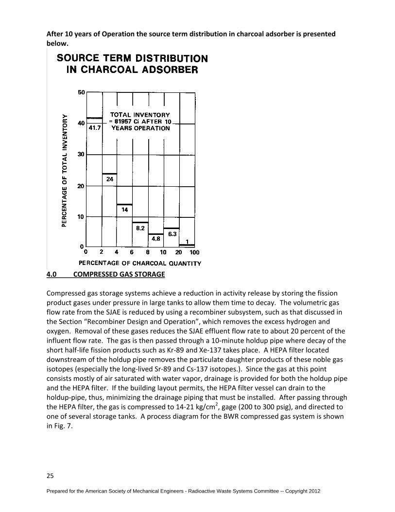
After 10 years of Operation the source term distribution in charcoal adsorber is presented below.
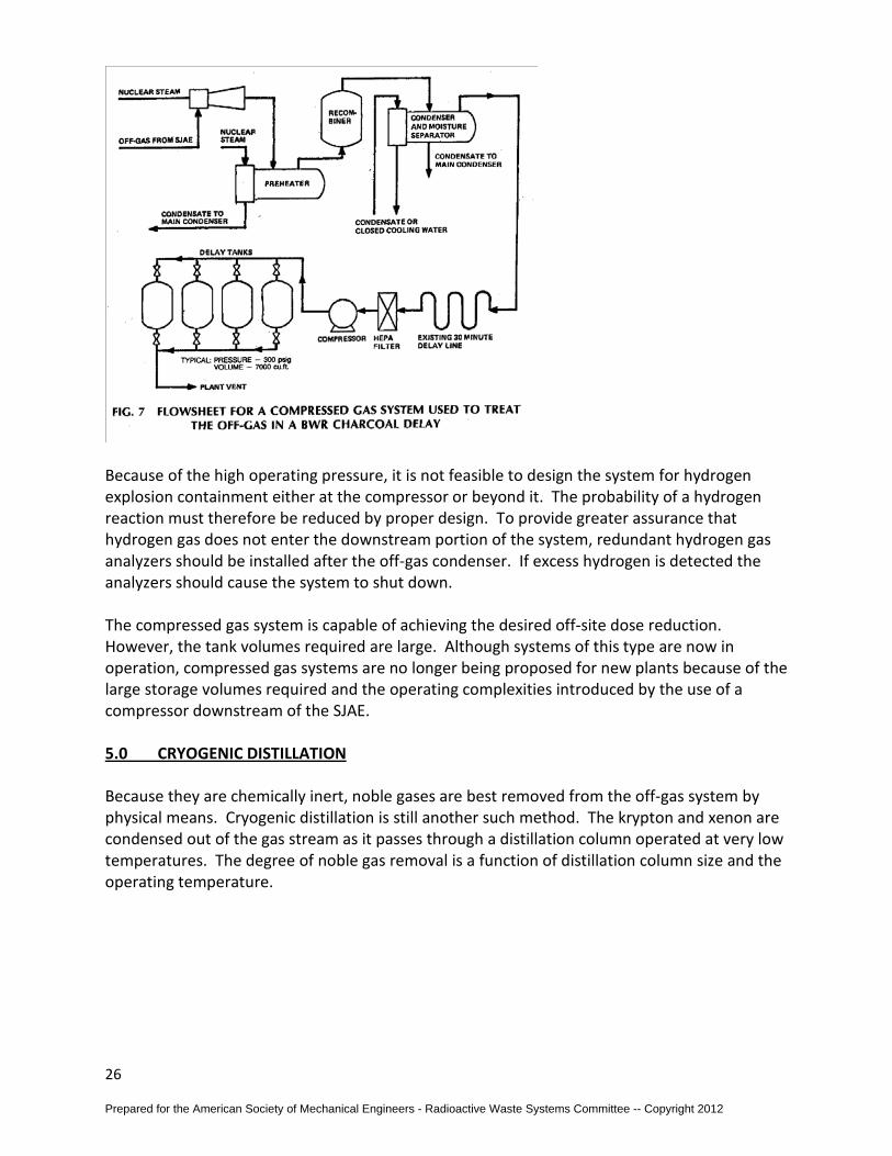
4.0 COMPRESSED GAS STORAGE Compressed gas storage systems achieve a reduction in activity release by storing the fission product gases under pressure in large tanks to allow them time to decay. The volumetric gas flow rate from the SJAE is reduced by using a recombiner subsystem, such as that discussed in the Section “Recombiner Design and Operation”, which removes the excess hydrogen and oxygen. Removal of these gases reduces the SJAE effluent flow rate to about 20 percent of the influent flow rate. The gas is then passed through a 10-minute holdup pipe where decay of the short half-life fission products such as Kr-89 and Xe-137 takes place. A HEPA filter located downstream of the holdup pipe removes the particulate daughter products of these noble gas isotopes (especially the long-lived Sr-89 and Cs-137 isotopes.). Since the gas at this point consists mostly of air saturated with water vapor, drainage is provided for both the holdup pipe and the HEPA filter. If the building layout permits, the HEPA filter vessel can drain to the holdup-pipe, thus, minimizing the drainage piping that must be installed. After passing through the HEPA filter, the gas is compressed to 14-21 kg/cm2, gage (200 to 300 psig), and directed to one of several storage tanks. A process diagram for the BWR compressed gas system is shown in Fig. 7.
Prepared for the American Society of Mechanical Engineers - Radioactive Waste Systems Committee -- Copyright 2012
26
Because of the high operating pressure, it is not feasible to design the system for hydrogen explosion containment either at the compressor or beyond it. The probability of a hydrogen reaction must therefore be reduced by proper design. To provide greater assurance that hydrogen gas does not enter the downstream portion of the system, redundant hydrogen gas analyzers should be installed after the off-gas condenser. If excess hydrogen is detected the analyzers should cause the system to shut down. The compressed gas system is capable of achieving the desired off-site dose reduction. However, the tank volumes required are large. Although systems of this type are now in operation, compressed gas systems are no longer being proposed for new plants because of the large storage volumes required and the operating complexities introduced by the use of a compressor downstream of the SJAE.
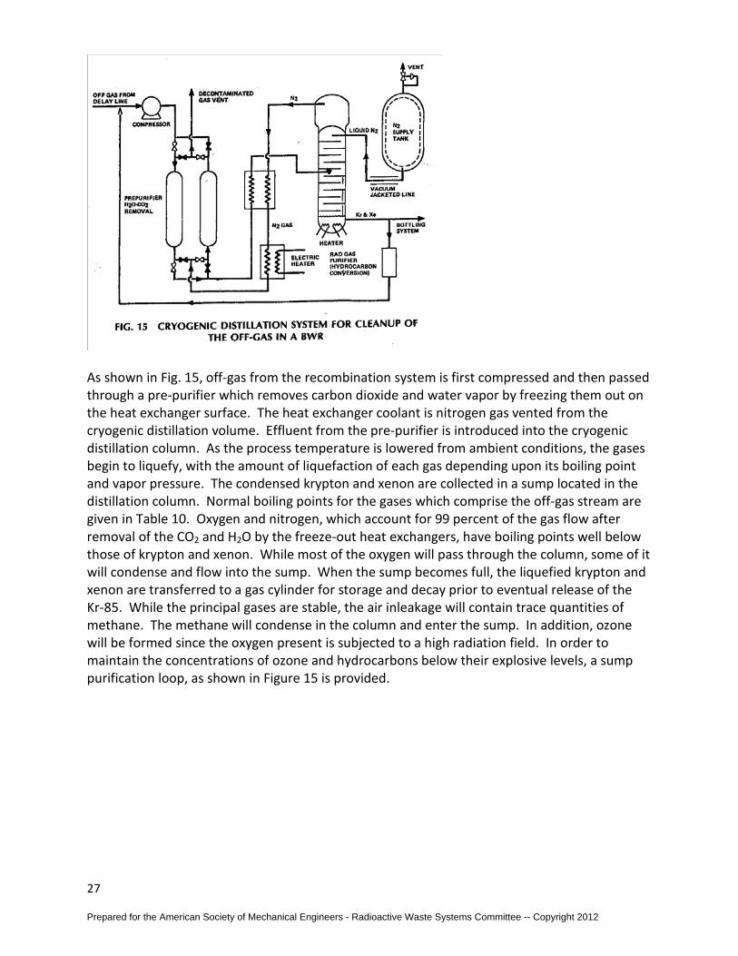
5.0 CRYOGENIC DISTILLATION Because they are chemically inert, noble gases are best removed from the off-gas system by physical means. Cryogenic distillation is still another such method. The krypton and xenon are condensed out of the gas stream as it passes through a distillation column operated at very low temperatures. The degree of noble gas removal is a function of distillation column size and the operating temperature.
Prepared for the American Society of Mechanical Engineers - Radioactive Waste Systems Committee -- Copyright 2012
27
As shown in Fig. 15, off-gas from the recombination system is first compressed and then passed through a pre-purifier which removes carbon dioxide and water vapor by freezing them out on the heat exchanger surface. The heat exchanger coolant is nitrogen gas vented from the cryogenic distillation volume. Effluent from the pre-purifier is introduced into the cryogenic distillation column. As the process temperature is lowered from ambient conditions, the gases begin to liquefy, with the amount of liquefaction of each gas depending upon its boiling point and vapor pressure. The condensed krypton and xenon are collected in a sump located in the distillation column. Normal boiling points for the gases which comprise the off-gas stream are given in Table 10. Oxygen and nitrogen, which account for 99 percent of the gas flow after removal of the CO2 and H2O by the freeze-out heat exchangers, have boiling points well below those of krypton and xenon. While most of the oxygen will pass through the column, some of it will condense and flow into the sump. When the sump becomes full, the liquefied krypton and xenon are transferred to a gas cylinder for storage and decay prior to eventual release of the Kr-85. While the principal gases are stable, the air inleakage will contain trace quantities of methane. The methane will condense in the column and enter the sump. In addition, ozone will be formed since the oxygen present is subjected to a high radiation field. In order to maintain the concentrations of ozone and hydrocarbons below their explosive levels, a sump purification loop, as shown in Figure 15 is provided.
Prepared for the American Society of Mechanical Engineers - Radioactive Waste Systems Committee -- Copyright 2012

28
Ozone concentrations can also be limited by eliminating oxygen from the influent stream. The oxygen is removed by adding hydrogen to the off-gas flow upstream of the recombiner. The effluent oxygen concentration is reduced to trace levels (to a few ppm) by the addition of a secondary preheater, recombiner, and condenser which are sized for the air inleakage flow rate as seen in Figure 16.
Small activity releases can occur from several points in a cryogenic distillation system. The small fraction of the inlet activity which is not condensed in the distillation column will be vented from the top of the column. This release represents only a small percentage of the total release from the system. The major sources of radioactive release are valve stem leakage and the venting of regeneration gas. These releases are included in the overall system
Prepared for the American Society of Mechanical Engineers - Radioactive Waste Systems Committee -- Copyright 2012
29
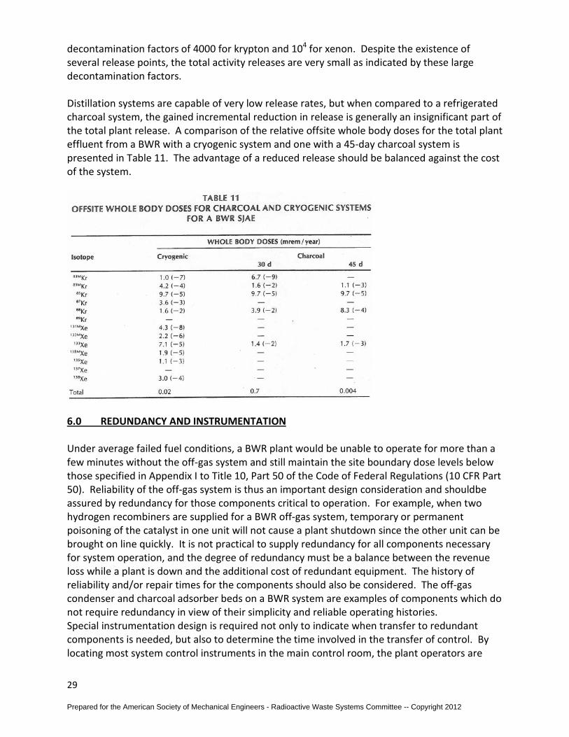
decontamination factors of 4000 for krypton and 104 for xenon. Despite the existence of several release points, the total activity releases are very small as indicated by these large decontamination factors. Distillation systems are capable of very low release rates, but when compared to a refrigerated charcoal system, the gained incremental reduction in release is generally an insignificant part of the total plant release. A comparison of the relative offsite whole body doses for the total plant effluent from a BWR with a cryogenic system and one with a 45-day charcoal system is presented in Table 11. The advantage of a reduced release should be balanced against the cost of the system.
6.0 REDUNDANCY AND INSTRUMENTATION Under average failed fuel conditions, a BWR plant would be unable to operate for more than a few minutes without the off-gas system and still maintain the site boundary dose levels below those specified in Appendix I to Title 10, Part 50 of the Code of Federal Regulations (10 CFR Part 50). Reliability of the off-gas system is thus an important design consideration and shouldbe assured by redundancy for those components critical to operation. For example, when two hydrogen recombiners are supplied for a BWR off-gas system, temporary or permanent poisoning of the catalyst in one unit will not cause a plant shutdown since the other unit can be brought on line quickly. It is not practical to supply redundancy for all components necessary for system operation, and the degree of redundancy must be a balance between the revenue loss while a plant is down and the additional cost of redundant equipment. The history of reliability and/or repair times for the components should also be considered. The off-gas condenser and charcoal adsorber beds on a BWR system are examples of components which do not require redundancy in view of their simplicity and reliable operating histories. Special instrumentation design is required not only to indicate when transfer to redundant components is needed, but also to determine the time involved in the transfer of control. By locating most system control instruments in the main control room, the plant operators are
Prepared for the American Society of Mechanical Engineers - Radioactive Waste Systems Committee -- Copyright 2012
30
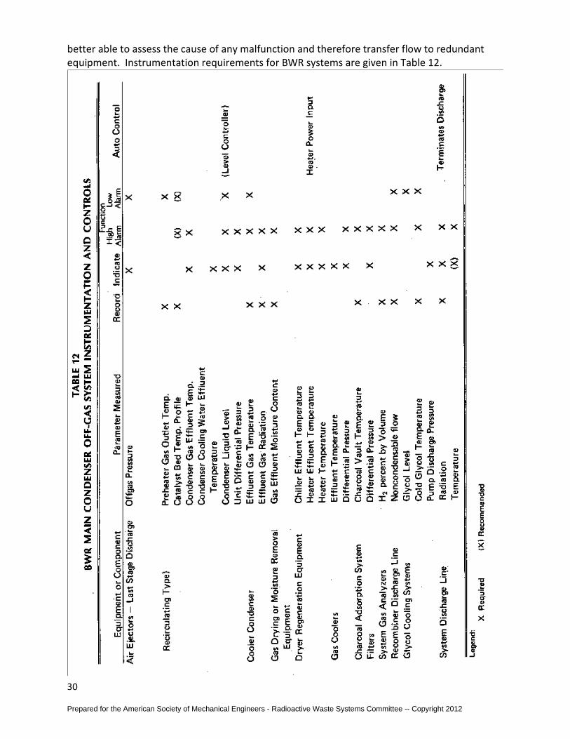
better able to assess the cause of any malfunction and therefore transfer flow to redundant equipment. Instrumentation requirements for BWR systems are given in Table 12.
Prepared for the American Society of Mechanical Engineers - Radioactive Waste Systems Committee -- Copyright 2012
31
7.0 PWR OFF-GAS SYSTEM DESCRIPTIONS Radioactive fission product gases , generated in the core of a pressurized water reactor (PWR), have the potential for leaking from the reactor fuel rods with a subsequent buildup in the primary coolant. The fission product gases could then be released to the containment by primary coolant leakage or they could enter the secondary system through tube leaks in the steam generator. The release of f ission product gases to the environment via the condenser air ejector or the containment purge air can be reduced if the noble gases are removed from the coolant. This can be accomplished during plant operation by passing the letdown flow through a gas stripper. To prevent releases when the vessel is opened, gases are also removed from the coolant following plant shutdown. The high radioactivity levels of the gases require a treatment system to remove these fission products prior to release. Below are several sources and system approaches for PWR Off-Gas treatment.
7.1 Design Gas Flow As indicated in Fig. 18, the waste gas system receives gases from the: (a) gas stripper; (b) reactor coolant drain tank vent; (c) equipment drain tank vent; (d) chemical and volume control system (CVCS) holdup tank vent; and (e) volume control tank purge. The gas from the gas stripper consists of nitrogen plus hydrogen in excess of that required for oxygen control. Hydrogen represents about 70% of the total gas. When the primary coolant is continuously
Prepared for the American Society of Mechanical Engineers - Radioactive Waste Systems Committee -- Copyright 2012
32
degassed, the flow rate will range from 0 to 1.4 scfm at standard temperature and pressure (0-0.04 m3 /min) with the average value being 0.25 scfm at standard conditions (0.007 m3 / min) [5]. The gas flow rates entering the waste gas system from the drain tank vents depend on the water flow rate into these tanks. Typical gas flow rates from the drain tanks will range from 0 to 0.57 m3 / min at standard temperature and pressure (0-20 scfm). The flow from the tanks is intermittent, while the flow from the stripper is continuous. Since the system must be sized to handle the larger intermittent flows, the compressor selected will be oversized for the flow from the gas stripper. As a result, the compressor will cycle on and off. To prevent excessive cycling, a surge tank should be installed upstream of the compressor. Many PWR off-gas systems are designed to operate at a pressure (gage) greater than 150 psig (1 0.5 kg I cm 2). At these pressures, it is not feasible to design compressors and large tanks to withstand a hydrogen detonation. To improve the safety of the system; redundant gas analyzers are installed to monitor the oxygen concentration [32]. If high oxygen concentrations are detected at the inlet, the system can automatically isolate the decay tanks. A more complete discussion of hydrogen detonation pressure was given previously in the section on Hydrogen Detonation.
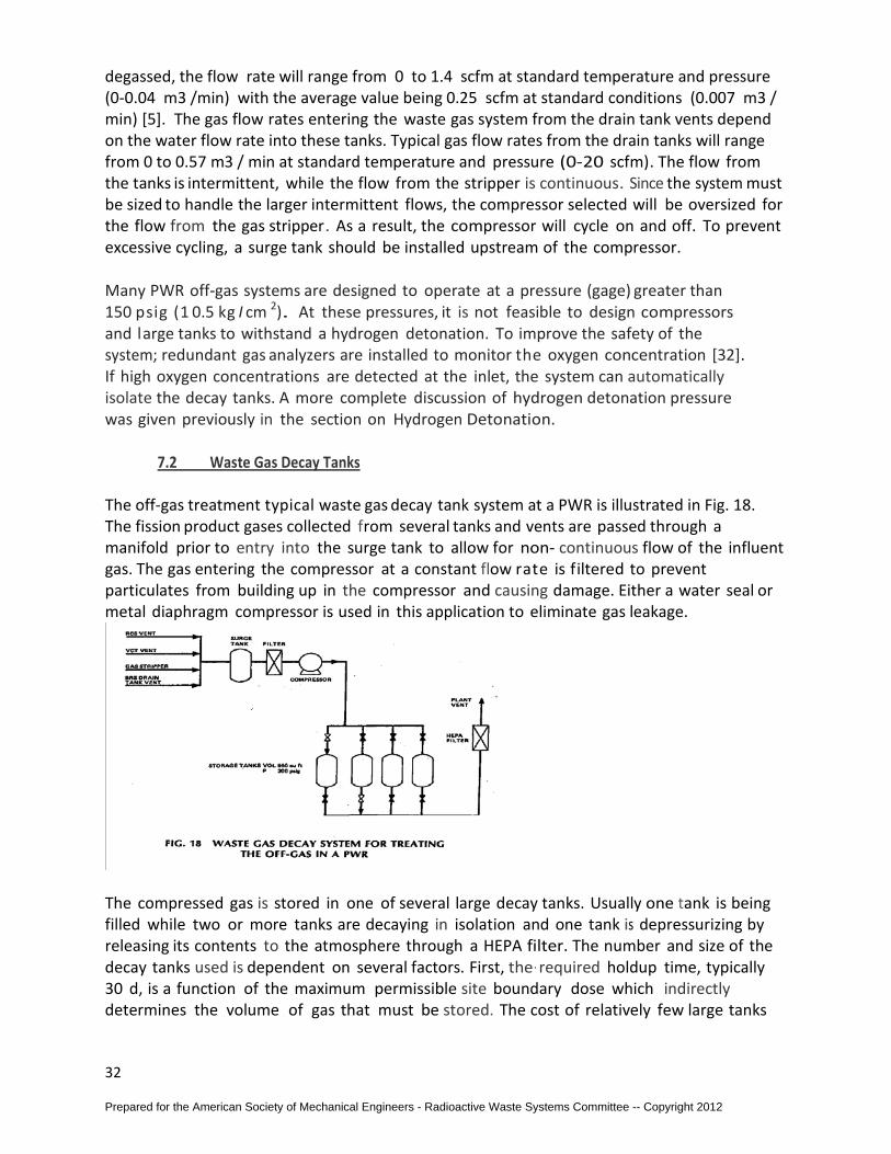
7.2 Waste Gas Decay Tanks
The off-gas treatment typical waste gas decay tank system at a PWR is illustrated in Fig. 18. The fission product gases collected from several tanks and vents are passed through a manifold prior to entry into the surge tank to allow for non- continuous flow of the influent gas. The gas entering the compressor at a constant flow rate is filtered to prevent particulates from building up in the compressor and causing damage. Either a water seal or metal diaphragm compressor is used in this application to eliminate gas leakage.
The compressed gas is stored in one of several large decay tanks. Usually one tank is being filled while two or more tanks are decaying in isolation and one tank is depressurizing by releasing its contents to the atmosphere through a HEPA filter. The number and size of the decay tanks used is dependent on several factors. First, the· required holdup time, typically 30 d, is a function of the maximum permissible site boundary dose which indirectly determines the volume of gas that must be stored. The cost of relatively few large tanks
Prepared for the American Society of Mechanical Engineers - Radioactive Waste Systems Committee -- Copyright 2012
33
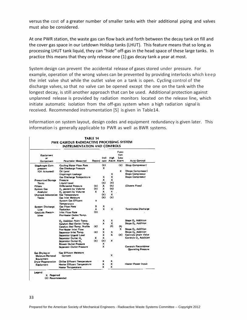
versus the cost of a greater number of smaller tanks with their additional piping and valves must also be considered. At one PWR station, the waste gas can flow back and forth between the decay tank on fill and the cover gas space in our Letdown Holdup tanks (LHUT). This feature means that so long as processing LHUT tank liquid, they can “hide” off-gas in the head space of these large tanks. In practice this means that they only release one (1) gas decay tank a year at most. System design can prevent the accidental release of gases stored under pressure. For example, operation of the wrong valves can be prevented by providing interlocks which keep the inlet valve shut while the outlet valve on a tank is open. Cycling control of the discharge valves, so that no valve can be opened except the one on the tank with the longest decay, is still another approach that can be used. Additional protection against unplanned release is provided by radiation monitors located on the release line, which initiate automatic isolation from the off-gas system when a high radiation signal is received. Recommended instrumentation [5] is given in Table14. Information on system layout, design codes and equipment redundancy is given later. This information i s generally applicable to PWR as well as BWR systems.
Prepared for the American Society of Mechanical Engineers - Radioactive Waste Systems Committee -- Copyright 2012
34
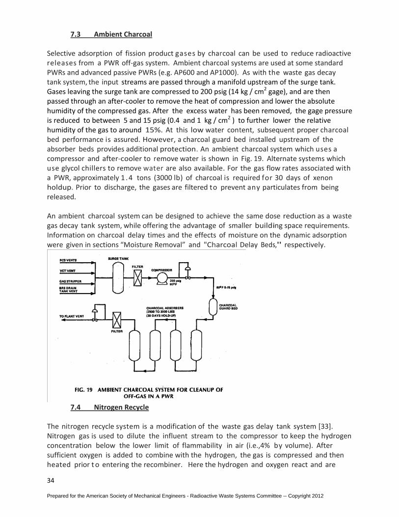
7.3 Ambient Charcoal Selective adsorption of fission product gases by charcoal can be used to reduce radioactive releases from a PWR off-gas system. Ambient charcoal systems are used at some standard PWRs and advanced passive PWRs (e.g. AP600 and AP1000). As with the waste gas decay tank system, the input streams are passed through a manifold upstream of the surge tank. Gases leaving the surge tank are compressed to 200 psig (14 kg / cm2 gage), and are then passed through an after-cooler to remove the heat of compression and lower the absolute humidity of the compressed gas. After the excess water has been removed, the gage pressure is reduced to between 5 and 15 psig (0.4 and 1 kg / cm2 ) to further lower the relative humidity of the gas to around 15%. At this low water content, subsequent proper charcoal bed performance is assured. However, a charcoal guard bed installed upstream of the absorber beds provides additional protection. An ambient charcoal system which uses a compressor and after-cooler to remove water is shown in Fig. 19. Alternate systems which use glycol chillers to remove water are also available. For the gas flow rates associated with a PWR, approximately 1 . 4 tons (3000 lb) of charcoal is required for 30 days of xenon holdup. Prior to discharge, the gases are filtered to prevent any particulates from being released. An ambient charcoal system can be designed to achieve the same dose reduction as a waste gas decay tank system, while offering the advantage of smaller building space requirements. Information on charcoal delay times and the effects of moisture on the dynamic adsorption were given in sections “Moisture Removal” and "Charcoal Delay Beds," respectively.
7.4 Nitrogen Recycle
The nitrogen recycle system is a modification of the waste gas delay tank system [33]. Nitrogen gas is used to dilute the influent stream to the compressor to keep the hydrogen concentration below the lower limit of flammability in air (i.e.,4% by volume). After sufficient oxygen is added to combine with the hydrogen, the gas is compressed and then heated prior t o entering the recombiner. Here the hydrogen and oxygen react and are
Prepared for the American Society of Mechanical Engineers - Radioactive Waste Systems Committee -- Copyright 2012
35
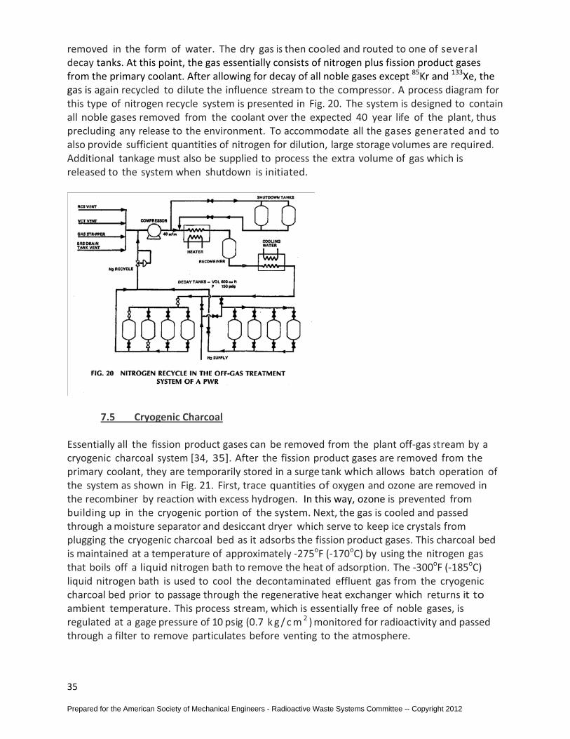
removed in the form of water. The dry gas is then cooled and routed to one of several decay tanks. At this point, the gas essentially consists of nitrogen plus fission product gases from the primary coolant. After allowing for decay of all noble gases except 85Kr and 133Xe, the gas is again recycled to dilute the influence stream to the compressor. A process diagram for this type of nitrogen recycle system is presented in Fig. 20. The system is designed to contain all noble gases removed from the coolant over the expected 40 year life of the plant, thus precluding any release to the environment. To accommodate all the gases generated and to also provide sufficient quantities of nitrogen for dilution, large storage volumes are required. Additional tankage must also be supplied to process the extra volume of gas which is released to the system when shutdown is initiated.
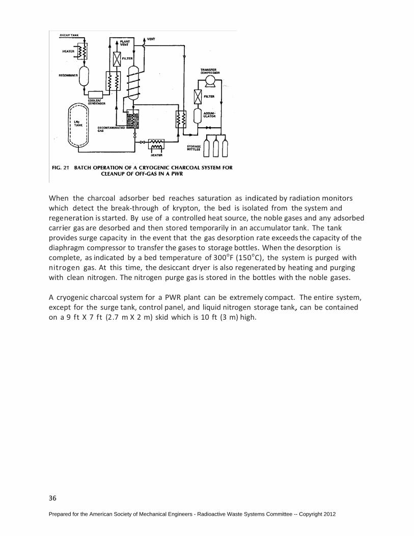
7.5 Cryogenic Charcoal Essentially all the fission product gases can be removed from the plant off-gas stream by a cryogenic charcoal system [34, 35]. After the fission product gases are removed from the primary coolant, they are temporarily stored in a surge tank which allows batch operation of the system as shown in Fig. 21. First, trace quantities of oxygen and ozone are removed in the recombiner by reaction with excess hydrogen. In this way, ozone is prevented from building up in the cryogenic portion of the system. Next, the gas is cooled and passed through a moisture separator and desiccant dryer which serve to keep ice crystals from plugging the cryogenic charcoal bed as it adsorbs the fission product gases. This charcoal bed is maintained at a temperature of approximately -275oF (-170oC) by using the nitrogen gas that boils off a liquid nitrogen bath to remove the heat of adsorption. The -300oF (-185oC) liquid nitrogen bath is used to cool the decontaminated effluent gas from the cryogenic charcoal bed prior to passage through the regenerative heat exchanger which returns it to ambient temperature. This process stream, which is essentially free of noble gases, is regulated at a gage pressure of 10 psig (0.7 k g / c m 2 ) monitored for radioactivity and passed through a filter to remove particulates before venting to the atmosphere.
Prepared for the American Society of Mechanical Engineers - Radioactive Waste Systems Committee -- Copyright 2012
36
When the charcoal adsorber bed reaches saturation as indicated by radiation monitors which detect the break-through of krypton, the bed is isolated from the system and regeneration is started. By use of a controlled heat source, the noble gases and any adsorbed carrier gas are desorbed and then stored temporarily in an accumulator tank. The tank provides surge capacity in the event that the gas desorption rate exceeds the capacity of the diaphragm compressor to transfer the gases to storage bottles. When the desorption is complete, as indicated by a bed temperature of 300oF (150oC), the system is purged with nitrogen gas. At this time, the desiccant dryer is also regenerated by heating and purging with clean nitrogen. The nitrogen purge gas is stored in the bottles with the noble gases. A cryogenic charcoal system for a PWR plant can be extremely compact. The entire system, except for the surge tank, control panel, and liquid nitrogen storage tank, can be contained on a 9 ft X 7 ft (2 .7 m X 2 m) skid which is 10 ft (3 m) high.
Prepared for the American Society of Mechanical Engineers - Radioactive Waste Systems Committee -- Copyright 2012
37
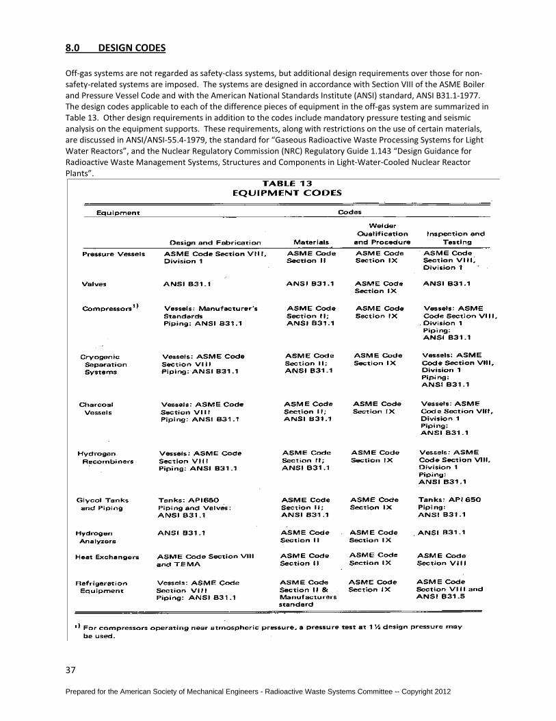
8.0 DESIGN CODES Off-gas systems are not regarded as safety-class systems, but additional design requirements over those for non-safety-related systems are imposed. The systems are designed in accordance with Section VIII of the ASME Boiler and Pressure Vessel Code and with the American National Standards Institute (ANSI) standard, ANSI B31.1-1977. The design codes applicable to each of the difference pieces of equipment in the off-gas system are summarized in Table 13. Other design requirements in addition to the codes include mandatory pressure testing and seismic analysis on the equipment supports. These requirements, along with restrictions on the use of certain materials, are discussed in ANSI/ANSI-55.4-1979, the standard for “Gaseous Radioactive Waste Processing Systems for Light Water Reactors”, and the Nuclear Regulatory Commission (NRC) Regulatory Guide 1.143 “Design Guidance for Radioactive Waste Management Systems, Structures and Components in Light-Water-Cooled Nuclear Reactor Plants”.
Prepared for the American Society of Mechanical Engineers - Radioactive Waste Systems Committee -- Copyright 2012
38
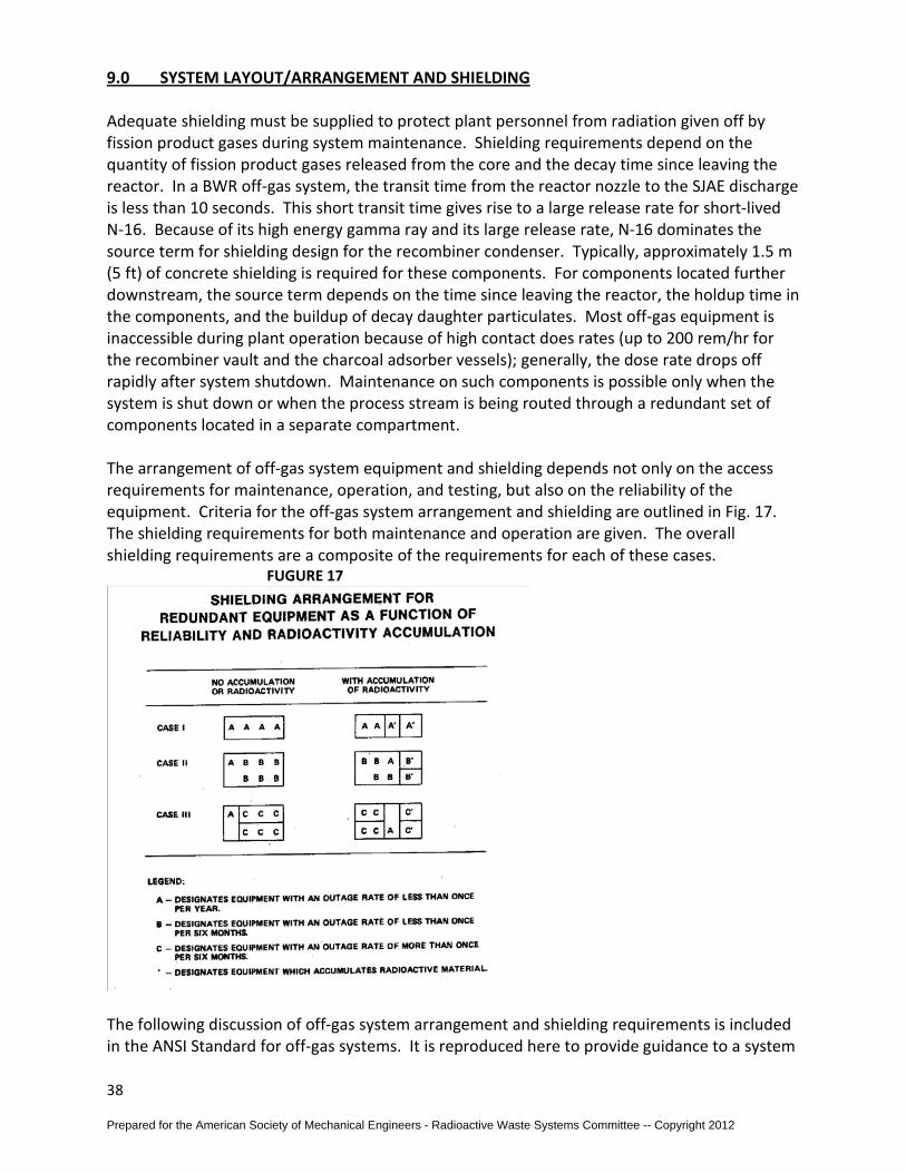
9.0 SYSTEM LAYOUT/ARRANGEMENT AND SHIELDING Adequate shielding must be supplied to protect plant personnel from radiation given off by fission product gases during system maintenance. Shielding requirements depend on the quantity of fission product gases released from the core and the decay time since leaving the reactor. In a BWR off-gas system, the transit time from the reactor nozzle to the SJAE discharge is less than 10 seconds. This short transit time gives rise to a large release rate for short-lived N-16. Because of its high energy gamma ray and its large release rate, N-16 dominates the source term for shielding design for the recombiner condenser. Typically, approximately 1.5 m (5 ft) of concrete shielding is required for these components. For components located further downstream, the source term depends on the time since leaving the reactor, the holdup time in the components, and the buildup of decay daughter particulates. Most off-gas equipment is inaccessible during plant operation because of high contact does rates (up to 200 rem/hr for the recombiner vault and the charcoal adsorber vessels); generally, the dose rate drops off rapidly after system shutdown. Maintenance on such components is possible only when the system is shut down or when the process stream is being routed through a redundant set of components located in a separate compartment. The arrangement of off-gas system equipment and shielding depends not only on the access requirements for maintenance, operation, and testing, but also on the reliability of the equipment. Criteria for the off-gas system arrangement and shielding are outlined in Fig. 17. The shielding requirements for both maintenance and operation are given. The overall shielding requirements are a composite of the requirements for each of these cases. FUGURE 17
The following discussion of off-gas system arrangement and shielding requirements is included in the ANSI Standard for off-gas systems. It is reproduced here to provide guidance to a system
Prepared for the American Society of Mechanical Engineers - Radioactive Waste Systems Committee -- Copyright 2012
39
designer. The logic shown in Fig. 17 and its relation to equipment and component reliability can be illustrated by the following three cases: A group of interrelated pieces of equipment and components, including valves, are designated as A, B, or C. It is assumed that all of these components require shielding for operation, because they handle radioactive gases. In addition, all of the components are subject to outages as a result of loss of function, maintenance, calibration, inspection or cyclic service life (e.g., dryer regeneration); with only the time between such outages as variable. Symbol A represents equipment and components having reliability such that the combined outage rate is greater than once per year and less than once per 6 months. Thus, to achieve the desired system availability, an installed spare would be provided. However, due to its relatively good reliability, maintenance could wait until the refueling shutdown. Symbol C represents equipment and components having reliability such that the combined outage rate is greater than once per 6 months. In this instance, maintenance should be accomplished within a reasonable time after the installed spare is placed in service and, therefore, access during plant operation would be required. An example is the gas dryer regeneration equipment. Symbols with a primed ( ‘ ), represent pieces of equipment which accumulate radioactive material, such as desiccant dryers or charcoal adsorbers, or equipment which may otherwise continue to have radiation levels due to mechanisms, such as plate out, that would constitute substantial radiation doses to personnel performing maintenance on adjacent equipment or components even after all of the equipment is shut down. The three cases are: Case I - Interrelated equipment is all of a category represented by Symbol A. Case II - Interrelated equipment is a mixture of equipment represented by Symbols A and B. Only one Symbol A – type is shown in the illustration for simplicity. Case III - Interrelated equipment is a mixture of equipment represented by Symbols A and C.
Mixtures of A, B and C are also possible, but they would be represented by a mixture of the diagrams shown in Figure 17.
Where activity accumulation occurs, the equipment represented by the Primed (‘ ) symbol would constitute a significant source of radiation to adjacent equipment after shutdown. The radioactive equipment would be separated (by shielding or distance) from the adjacent equipment. For Case I, an added shield wall would be required as illustrated. For Case II, an added shield wall would also be required to shield the adjacent equipment. Depending upon the means provided for maintenance of the radioactive equipment, a shield wall separating the parallel radioactive components may also be required. In Case III, the parallel radioactive components must be shielded from one another so one can be maintained during operation of the other.
Prepared for the American Society of Mechanical Engineers - Radioactive Waste Systems Committee -- Copyright 2012
40
The final arrangement and shielding plan would be determined from maintenance considerations. An obvious rule derived from inspection of the diagram is that shielding may be minimized by locating all components which accumulate radioactive materials at one end of the shielding complex. Other factors, such as piping requirements, also need consideration in determining the trade-off between shielding and piping complexity involved in the location of equipment. Although the cases described for illustrative purposes contain only four separate pieces of equipment or components, the logic presented can be extended to include any number of interrelated pieces of equipment and components. Where skid mounting or other mechanical combination of components is used, it is more probable that equipment and components of various degrees of reliability will be mixed and represented by a common symbol. The reliability of the aggregate will then be that of the least reliable component. The arrangement and shield requirements shall be determined accordingly.
Prepared for the American Society of Mechanical Engineers - Radioactive Waste Systems Committee -- Copyright 2012
41
10.0 TROUBLES TO AVOID WITH OFF-GAS SYSTEMS
1- For SJAE flow interruption, reactor-shut down, and restart see 2.3, pages 12 to 17. 2- For steam and air recycle systems see page 12. This should be couple with being aware
that catalytic material used in the recombiner of recycle systems should not be subject to dusting since experience has shown that the dust will be transported upstream of the recombiner where it can plate out and can cause hydrogen detonation problems.
3- The completeness of the recombination reaction will depend on the amount of excess oxygen present from a BWR system which is a function of the air inleakage to the main condenser. To compensate for low air inleakage rates, some off-gas systems have incorporated an air supply of about 0.17 m3/min at STP, or 6 scfm, from the instrument air system.
4- Mercury (Hg) is the main permanent poison to recombiner catalyst and should be completely avoided. Catalysts baskets should be washed and vacuumed prior to installation.
5- Being aware that the energy given off by the catalytic reaction of hydrogen and oxygen will result in a temperature rise of 70oC (125oF) for every percent of hydrogen in the influent gas will help to verify temperatures and hydrogen/oxygen percent instruments around the recombiner.
6- Off-Gas system condensate which includes the dilution steam and the water formed by recombination of hydrogen and oxygen should be routed back to the main condenser to maintain the primary coolant water inventory and also to reduce the flow to the radwaste system.
7- Hydrogen and oxygen generated in the BWR reactor core by radiolysis of the cooling water will be removed from the primary coolant by the off-gas treatment system. Because of the explosive nature of these gases, their presence in the system must be considered in the design phase. The potential hazards associated with processing hydrogen and oxygen can be reduced or eliminated by diluting the off-gas stream so that the hydrogen concentrations are kept below the explosive limit, eliminating ignition sources, and by designing the system with the capability to contain an explosion should one occur.
8- To prevent high hydrogen concentrations from occurring in the system downstream of the recombiner, the outlet hydrogen concentration is monitored downstream of the off-gas condenser, after the dilution steam has been removed. In the event of a recombiner failure, high hydrogen concentrations will be detected and an alarm will be triggered. The alarm signal can be used to initiate a system shutdown to prevent an unsafe condition. An additional safety feature that can be incorporated into the system is instrumentation that can detect, alarm, and initiate shutdown upon loss of steam dilution flow.
9- Operating experience with BWR off-gas systems indicates that several hydrogen explosions have occurred during their operation and maintenance. (see 2.4) The causes of the explosions have been traced to many sources, including: spark from ungrounded metal parts; sparks from rapid valve closure; catalyst fines which have migrated to areas of high hydrogen concentration; and release of gas into the structures housing the system. Make sure that the entire grounding system is operational and ground HEPA
Prepared for the American Society of Mechanical Engineers - Radioactive Waste Systems Committee -- Copyright 2012

42
filter elements to pressure vessel housings if metal framed HEPAs are used in the off-gas system. (Note this should not be confused with HVAC ventilation system HEPA filters.)
10- Condensate drainage from recombiner preheaters and condensers is very important to maintain a dry gas mixture at the inlet of the recombiner and non-saturated steam at the outlet. Be aware that the steam which is used to heat the pipe will condense at an excessive rate until the pipe reaches its operating temperature. The drainage lines must be sized to handle the condensation rates during system startup. Also, since the high gas flow rates will cause the condensed water to move rapidly down the pipe, the water may completely bypass the drain and enter the downstream equipment if small drain lines are used. Therefore, the drains should be designed to collect water from a significantly larger area than the drain line itself. Another significant design consideration is the heat loss from the system before the gases reach the recombiner. As heat is lost through the insulation on the pipe, steam will begin to condense and form water droplets. Adequate moisture removal and drainage must provided upstream of the preheater to ensure proper operation. Since water droplet will still be entrained in the gas mixture, the system must be designed to remove water droplets from the gas. Their evaporation in the preheater is difficult because of the higher heat input rate required and the limited residence time. If these water droplets are not evaporated in the preheater then they can enter the recombiner and quench the catalyst, thus preventing complete recombination of the hydrogen and oxygen gases.
11- Recombination of hydrogen and oxygen is achieved by using a platinum/palladium-type catalyst with either a metallic or ceramic base. Hydrogen in the off-gas air is diluted to keep its concentration below the 4 percent by volume (lower flammability level) and to prevent excessive post-reaction temperature from occurring within the recombiner.
12- Moisture removal Upon leaving the off-gas condenser, the gas stream is saturated with water at a temperature of approximately 50o C (120oF). At this point in the process, the gas stream is essentially all air. For a flow rate of 1 m3/min at standard temperature and pressure (40 scfm), the required water removal rate is about 8.6 kg/hr (19 lb/hr…2-3 gal/hr). Moisture removal for charcoal delay of off-gas systems is usually accomplished with a combination of cooler condensers and desiccant dryers. The type of components added to each system depends on the quantity of water vapor entrained and the required outlet moisture content. The bulk of this water vapor can be removed by passing the gas through a cooler condenser which reduces the temperature to 4oC (40oF). This temperature reduction removes approximately 90 percent of the water contained in the gas. The impact of temperature on the water vapor content of the gas can be seen on the psychometric chart presented in Fig. 9, page 23.
13- A molecular sieve bed will continue to remove water from the gas until the bed becomes saturated. When saturation occurs, flow is transferred to an alternate bed which is free of water. The saturated bed can be regenerated by heating the bed to evaporate the water which had been adsorbed. The regeneration loop consists of a blower, heater, and dryer chiller which condition the air before it is circulated through the saturated bed. Prior to entering the saturated desiccant bed, the air is heated to between 150o and 200o C (300o to 400oF) to affect water evaporation from the bed. Water-saturated air leaving the bed is passed through a chiller which removes water by condensation. Recirculation of the dried air is continued until the bed is returned to its
Prepared for the American Society of Mechanical Engineers - Radioactive Waste Systems Committee -- Copyright 2012
43
initial dry condition. Water removed from the regeneration loop can be routed to either the main condenser or the liquid radwaste system. A typical flow diagram for the moisture removal subsystem using a closed-loop regeneration cycle is shown in Fig. 10, page 23. Additionally, be sure not to overheat the molecular sieve material (usually 3A) above 400oF, as this could permanently damage its properties. Return the regenerated water to the main condensers rather than the radwaste system.
14- Since the adsorption efficiency of the charcoal beds is adversely affected by water and chemical impurities, a number of systems incorporate a charcoal guard bed upstream of the charcoal absorbers. If a system malfunction results in excessive moisture or other gases, the guard bed will remove these contaminants before they reach the main delay beds. Since the guard bed has a volume of 0.06 to 0.08 m3 (2 to 3 ft3), it is more easily replaced than the charcoal in the large bed. As additional protection against a spike in the gas release rate or an excessive water flow to the first absorber bed, some systems are designed so that the first bed can be isolated and the off-gas flow directed to the second bed.
15- Avoid exposing charcoal to ambient environments which are humid or filled with chemical vapors (e.g. paint fumes).
16- Loading charcoal into absorber vessels should be carefully controlled by procedure so as to achieve the design packed bed density. Charcoal must be slowly poured via serpentine hose/trunk as close to the terminal location as possible. Form several cones by rotating and raising the hose/trunk to minimize free fall. Never vibrate the vessel as this will expand the bed rather than settle the charcoal.
17- Off-gas system valve leaks and unplanned releases can occur and if this is a frequent problem then modifications should be considered. In PWR’s where pressurized decay tanks are used and diaphragm valves are the source of constant leaks this conversion may be the solution: the system can be converted to ambient pressure by bypassing compressors, load decay tanks with charcoal, and provide a blower downstream of the decay tanks. The cost would be easily offset by avoiding the costs of valve diaphragm maintenance, regulatory compliance, and public relations media costs. In pressurized systems, use of double stem sealed valves with a port between the stem seals has the benefit that if lower seal begins to leak, the port is either 1) pressurized (with instrument air or nitrogen) and the leak would be into the off-gas system or 2) sent to a pressure instrument that detects the leak and provides an alarm.
18- Redundancy and instrumentation: Under average failed fuel conditions, a BWR plant would be unable to operate for more than a few minutes without the off-gas system and still maintain the site boundary dose levels below those specified in Appendix I to Title 10, Part 50 of the Code of Federal Regulations (10 CFR Part 50). Reliability of the off-gas system is thus an important design consideration and should, therefore, be assured by redundancy for those components critical to operation. For example, when two hydrogen recombiners are supplied for a BWR off-gas system, temporary or permanent poisoning of the catalyst in one unit will not cause a plant shutdown since the other unit can be brought on line quickly. It is not practical to supply redundancy for all components necessary for system operation, and the degree of redundancy must be a balance between the revenue loss while a plant is down and the additional cost of redundant equipment. The previous history of reliability and/or repair times for the components should also be considered. The preheater, off-gas condenser and charcoal
Prepared for the American Society of Mechanical Engineers - Radioactive Waste Systems Committee -- Copyright 2012
44
adsorber beds on a BWR system are examples of components which do not require redundancy in view of their simplicity and reliable operating histories.
19- Special instrumentation design is required not only to indicate when transfer to redundant components is needed, but also to determine the time involved in the transfer of control. By locating most system control instruments in the main control room, the plant operators are better able to assess the cause of any malfunction and therefore transfer flow to redundant equipment. Instrumentation requirements for BWR systems are given in Table 12, page31.
20- Sample lines need to be sloped back to source, insulated and heat traced in most instances. Select tubing or piping materials that are compatible with the samples that are to be analyzed.
Prepared for the American Society of Mechanical Engineers - Radioactive Waste Systems Committee -- Copyright 2012
45
11.0 ACTIVATED CHARCOAL SELECTION and PLANNING Introduction Several decades ago it was necessary to supply 200 tons of activated charcoal for a number of BWR Off-Gas systems. The activated carbon adsorbent was used for the long-term delay of Xenon (Xe) and Krypton (Kr) isotopes. Upon examination of the activated carbon market it was discovered that there were many product types and producer choices, with little if any performance data available for any of them relative to dynamic adsorption of radioactive noble gases. In order to not compromise the Off-Gas systems performance or reliability the services of Dr. Underhill of Harvard University were retained to conduct a testing program, the result of which would supply confidence factor for the eventual choice of carbon. Following is a brief description of important factors peculiar to these tests as well as clarification of confusing or conflicting data presented in the testing. Testing Program The purpose of the testing program was the determination of the dynamic adsorption coefficients for Kr and Xe gases of various activated carbon adsorbents. The delay times of concern were those produced by packed columns operated at -20o F* and 80o F at 1 atmosphere. [*-20o F was the temperature of concern, however all tests were mistakenly run at -20o C (-4o C)] Nine (9) carbons, made of three (3) different base materials and representing six (6) different manufacturers were tested. All nine carbons were tested in the “As-received” condition at -20o C. These results were analyzed and four desirable representative samples were dried, moisture content recorded, and re-tested at -20o C. Two samples were also tested at ~80o F in the “As-received” condition. Testing Apparatus Figure 1 shows a schematic diagram of the experimental test system. In this system, dry air from a compressed gas cylinder is passed at a constant flow to a cooling coil immersed in an ethylene glycol and water bath. The charcoal under analysis is also contained in a bed placed in the same coolant bath. Effluent air from the cooling coil passes through the charcoal bed and then out of the coolant bath to an ionization chamber and through a wet test meter where the activity and total volume of air are respectively measured. The temperature in the coolant bath is controllable to within +/- 0.1o C over a range of temperatures from well above ambient to -30o C. This particular coolant bath is an excellent piece of scientific equipment, and it performed without fault during the tests described herein. The volume of air having passed through the system can be measured with less than 1% error. Thus the system described here can provide highly accurate data on a laboratory scale for the determination of adsorption coefficients. To make an adsorption measurement, a measured amount of charcoal is placed in the test bed, brought to the desired temperature, and a pulse of fission gas injected in the dry air passing
Prepared for the American Society of Mechanical Engineers - Radioactive Waste Systems Committee -- Copyright 2012
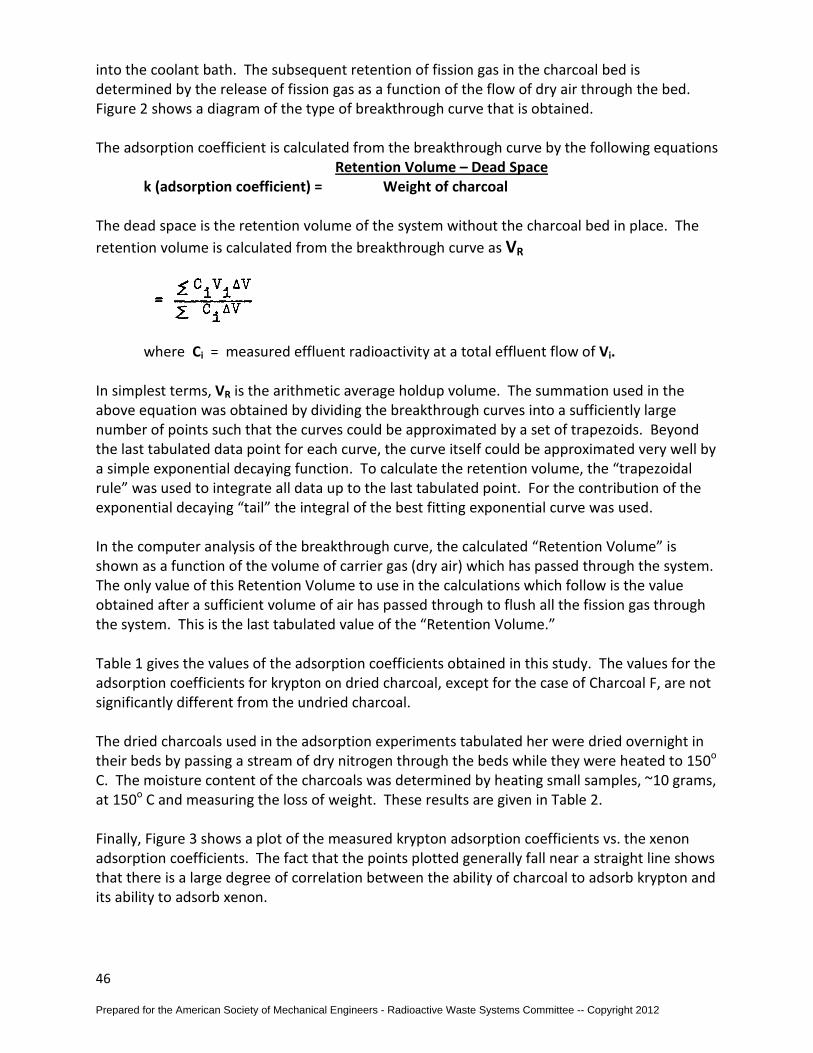
46
into the coolant bath. The subsequent retention of fission gas in the charcoal bed is determined by the release of fission gas as a function of the flow of dry air through the bed. Figure 2 shows a diagram of the type of breakthrough curve that is obtained. The adsorption coefficient is calculated from the breakthrough curve by the following equations Retention Volume – Dead Space
k (adsorption coefficient) = Weight of charcoal The dead space is the retention volume of the system without the charcoal bed in place. The retention volume is calculated from the breakthrough curve as VR
where Ci = measured effluent radioactivity at a total effluent flow of Vi.
In simplest terms, VR is the arithmetic average holdup volume. The summation used in the above equation was obtained by dividing the breakthrough curves into a sufficiently large number of points such that the curves could be approximated by a set of trapezoids. Beyond the last tabulated data point for each curve, the curve itself could be approximated very well by a simple exponential decaying function. To calculate the retention volume, the “trapezoidal rule” was used to integrate all data up to the last tabulated point. For the contribution of the exponential decaying “tail” the integral of the best fitting exponential curve was used. In the computer analysis of the breakthrough curve, the calculated “Retention Volume” is shown as a function of the volume of carrier gas (dry air) which has passed through the system. The only value of this Retention Volume to use in the calculations which follow is the value obtained after a sufficient volume of air has passed through to flush all the fission gas through the system. This is the last tabulated value of the “Retention Volume.” Table 1 gives the values of the adsorption coefficients obtained in this study. The values for the adsorption coefficients for krypton on dried charcoal, except for the case of Charcoal F, are not significantly different from the undried charcoal. The dried charcoals used in the adsorption experiments tabulated her were dried overnight in their beds by passing a stream of dry nitrogen through the beds while they were heated to 150o C. The moisture content of the charcoals was determined by heating small samples, ~10 grams, at 150o C and measuring the loss of weight. These results are given in Table 2. Finally, Figure 3 shows a plot of the measured krypton adsorption coefficients vs. the xenon adsorption coefficients. The fact that the points plotted generally fall near a straight line shows that there is a large degree of correlation between the ability of charcoal to adsorb krypton and its ability to adsorb xenon.
Prepared for the American Society of Mechanical Engineers - Radioactive Waste Systems Committee -- Copyright 2012
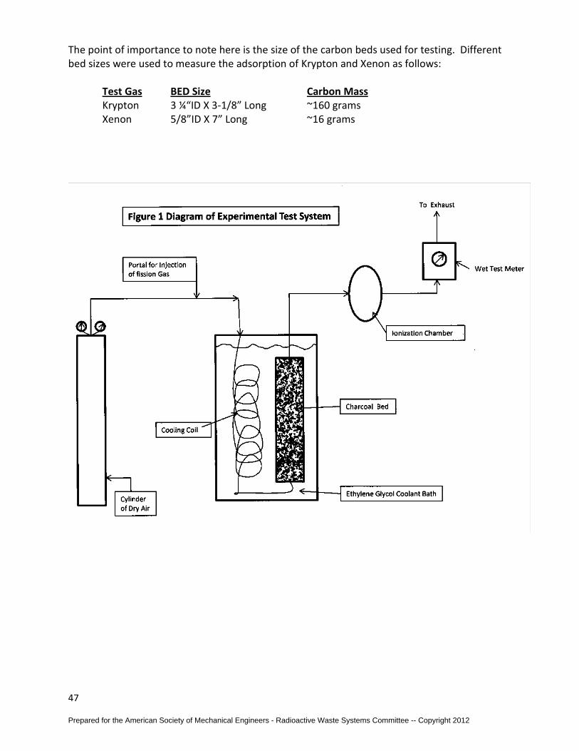
47
The point of importance to note here is the size of the carbon beds used for testing. Different bed sizes were used to measure the adsorption of Krypton and Xenon as follows: Test Gas BED Size Carbon Mass Krypton 3 ¼“ID X 3-1/8” Long ~160 grams Xenon 5/8”ID X 7” Long ~16 grams
Prepared for the American Society of Mechanical Engineers - Radioactive Waste Systems Committee -- Copyright 2012

48
Results The entire test data generated was computer analyzed for each test run. As previously mentioned the refrigerated test runs were done at -20oC instead of -20oF as desired. Dr. Underhill derived a conversion factor for the krypton and xenon values based on data available from extensive testing done by himself and many experts (national and international) in this field. These conversion factors are a follows: Krypton- K-20C = K-20F X 1.29 Xenon- K-20C = K-20F X 1.45
Prepared for the American Society of Mechanical Engineers - Radioactive Waste Systems Committee -- Copyright 2012
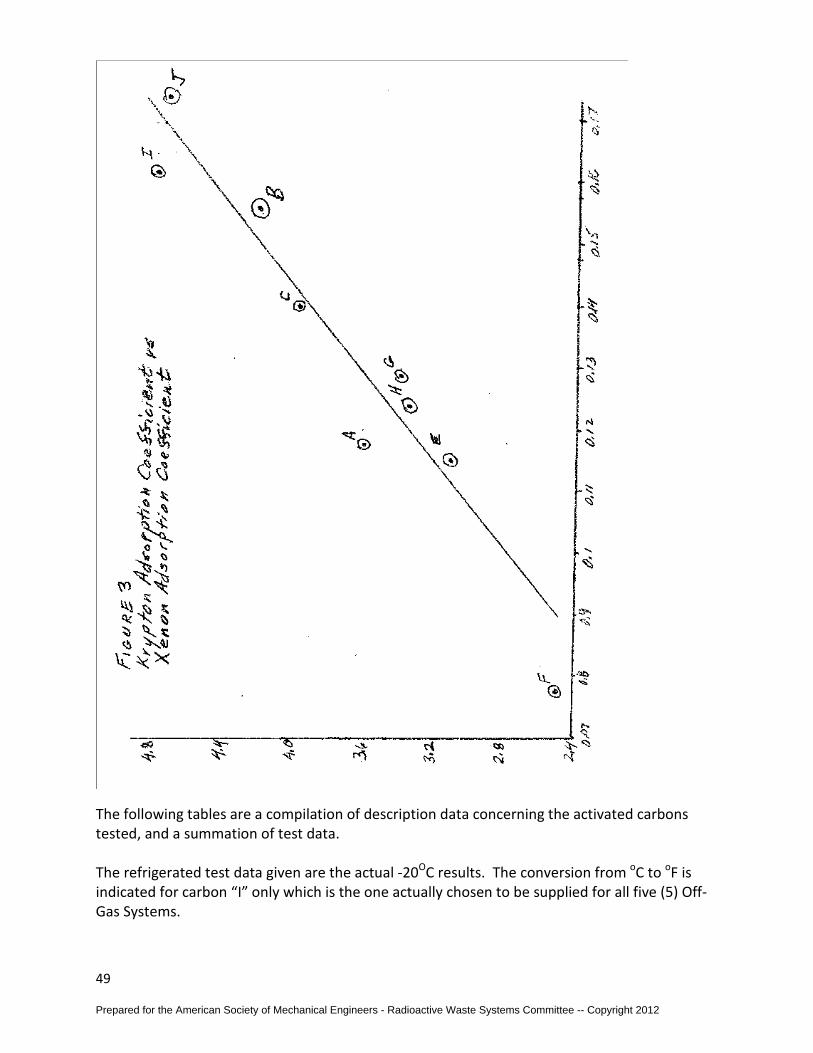
49
The following tables are a compilation of description data concerning the activated carbons tested, and a summation of test data. The refrigerated test data given are the actual -20OC results. The conversion from oC to oF is indicated for carbon “I” only which is the one actually chosen to be supplied for all five (5) Off-Gas Systems.
Prepared for the American Society of Mechanical Engineers - Radioactive Waste Systems Committee -- Copyright 2012

50
The adsorption tests performed on the dried carbon were for krypton only. The xenon adsorption coefficients indicated were extrapolated based on other test results and the trent indicated by the krypton results.
ACTIVATED CARBONS AS PRESENTED IN CONTRACT
Nuclear Power Adsorption Coefficient Design Packed Bed Plant KKr Kxe Temperature oF Density lb/ft3
Z 90 2400 -20 30 M 110 3600 -20 30 C 72 2340 -20 30-33 D 18.5 330 75 30-33 S 25 440 75 30-33
ACTIVATED CARBONS: TEST DATA ID Manufacturer Type Base Surface
Area M2/gm
Adsorption Coefficient
As Received Cc/gm @ 0oF
Adsorption Coefficient
After Drying Cc/gm @ 0oF
KKr / KXe KKr / KXe A Sutcliff-Speekman 203B Coal 500-600 118 / 3670 154 / 4312 B “ 203C Coconut 500-600 155 / 4340 C “ 207C Coconut 1000-1050 140 /4020 D North American
Carbon G210 Coconut 950-1050 Sample never
received Sample never
received E Pittsburgh (Calgon) BPL Coal 1050-1150 115 / 3150 F Union Carbide
Columbia MBQ Coal 500 77 / 2560 124 / 4090
G “ L Coconut 1300 130 / 3420 H Witco Chemical 337 Petroleum 1250-1350 124 / 3040 I “ 235 Petroleum 900-1000 157 / 4720 161 / 4840 J Barnebey Cheney AK Coconut 171 / 4850 174 / 4935
ACTIVATED CARBONS: PHYSICAL DATA
ID Type Base Surface Area
M2/gm
Density lb/ft3
Hardness %
CCl4 Adsorb.
% wt.
MESH Moisture %
ASH %
A 203B Coal 500-600 31 20-30 8x16 6-8 B 203C Coconut 500-600 31 97 20-30 1 4 C 207C Coconut 1000-1050 30-32 55-65 8x16 3 D G210 Coconut 950-1050 30-33 95 60 8x16 3 4 E BPL Coal 1050-1150 30 60-65 6x16 2 8
Prepared for the American Society of Mechanical Engineers - Radioactive Waste Systems Committee -- Copyright 2012

51
F MBQ Coal 500 39 99 35 1 7 G L Coconut 1300 32 5 H 337 Petroleum 1250-1350 28-31 8x16 .75 I 235 Petroleum 900-1000 31-35 95 40-50 4x10 .75 1 J AK Coconut 35 99 8x14 2
TABLE 1 MEASURED ADSORPTION COEFFICIENTS OF KRYPTON AND XENON ON REPRESENTATIVE
CHARCOALS Measurements were for adsorption from dry air at 1 atm. and -20oC
Results are in liters (30oC and 1 atm/gm
Charcoal Type
Krypton Adsorption Coefficient
Krypton Adsorption
Coefficient
Krypton Adsorption
Coefficient of Dried
Charcoal
Xenon Adsorption Coefficient
Xenon Adsorption Coefficient
Measured Values
Average Measured Values
Average
A 0.116 3.62 0.120 0.118 3.60 3.61
B 0.155 4.39* 0.156 0.156 0.154 4.22 4.23 4.25
C 0.138 3.95 0.142 0.140 4.03 3.98
E 0.114 3.13 0.116 0.115 3.07 3.10
F 0.077 0.077 0.125 2.34 2.64 2.49
G 0.128 3.40 0.130 0.129 3.41 3.40
H 0.124 3.33 0.123 0.124 3.40 3.36
I 0.159 0.162 4.75 0.154 0.156 4.87 4.80
Prepared for the American Society of Mechanical Engineers - Radioactive Waste Systems Committee -- Copyright 2012
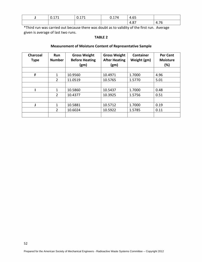
52
J 0.171 0.171 0.174 4.65 4.87 4.76
*Third run was carried out because there was doubt as to validity of the first run. Average given is average of last two runs.
TABLE 2
Measurement of Moisture Content of Representative Sample
Charcoal Type
Run Number
Gross Weight Before Heating
(gm)
Gross Weight After Heating
(gm)
Container Weight (gm)
Per Cent Moisture
(%)
F 1 10.9560 10.4971 1.7000 4.96 2 11.0519 10.5765 1.5770 5.01 I 1 10.5860 10.5437 1.7000 0.48 2 10.4377 10.3925 1.5756 0.51 J 1 10.5881 10.5712 1.7000 0.19 2 10.6024 10.5922 1.5785 0.11
Prepared for the American Society of Mechanical Engineers - Radioactive Waste Systems Committee -- Copyright 2012

53
12.0 REFERENCES [1] "Calculation of Releases of Radioactive Materials in Gaseous and Liquid Effluents from Boiling Water Reactors", NUREG-16, Rev. 1, U. S. Nuclear Regulatory Commission, January 1979. [2] "Calculation of Releases of Radioactive Materials in Gaseous and Liquid Effluents from Pressurized Water Reactors", NUREG-17, Rev. 0, U. S. Nuclear Regulatory Commission, April 1976. [3] "Design, Testing, and Maintenance Criteria for Normal Ventilation Exhaust System Air Filtration and Adsorption Units of Light-Water-Cooled Nuclear Power Plants", Regulatory Guide 1.140, Rev. 1, U. S. Nuclear Regulatory Commission, October 1979. [4] "Calculation of Annual Doses to Man from Routine Releases of Reactor Effluents for the Purpose of Evaluating Compliance with 10CFRPart 50, Appendix. I, Reg Guide 1.109, Rev. 1, U. S. Nuclear Regulatory Commission, October 1977. [5] American National Standard, "Gaseous Radioactive Waste Processing Systems for Light Water Reactor Plants,'' ANSI-55 .4, 1979. [6] Larlee, W. D., "Recombiners for .Nuclear Power Generation," Air Correction Division, Universal Oil Products Company, Darien, Connecticut. [7] Susquehanna Steam Electric Station Units 1 and 2 Final Safety Analysis Report, Section 11.3, ·February 1972. [8] Nuclear Power Experience, Volume BWR-2 and Volume PWR-2, Experiences, Published by Nuclear Power Experience Inc., Encino, California. [9] Slifer, B. C. Peterson, T. G., "Hydrogen Flammability and Burning Characteristics in BWR Containments," NED0-10812, Licensing Topical Report, General Electric Co., April 1973. [10] Pigford, T. H., "Explosion and Detonation Properties of Mixtures of Hydrogen, Oxygen, and Water Vapor," ORNL-1322, Oak Ridge National Laboratory, August 1952. [11] Lewis, B., Von Elbe, G., Combustion, "Flames and Explosion of Gases," Academic Press, New York, Second Edition, 1961 \ [12] Ordin, P. M., "Hydrogen-Oxygen Explosions in Exhaust Ducting," NACA, Technical Note 3935, 1957. [13] Kovach, L., "Investigation of Incident and Reflectant Detonation Waves in Stoichiometric Hydrogen-Oxygen Mixtures at Elevated Pressure," Thesis at Ohio State University, March 1969.
Prepared for the American Society of Mechanical Engineers - Radioactive Waste Systems Committee -- Copyright 2012

54
[14] Martin, P. J., "Reflection of Gaseous Detonation Waves," General Electric Research and Development Center, Schenectady, New York, December 1967. [15] Smith, J. B., "Explosion Pressures in Industrial Piping Systems," Annual Convention of International Acetylene Assn., Pittsburgh, Pennsylvania, April 25-26, 1949. [16] Juvinall, R. C., "Engineering Considerations of Stress, Strain, and Strength," McGraw- Hill Book Company, New York, 1967. [17] Manjoine, M. J., "Influence of Rate of Strain and Temperature on Yield Stress of Mild Steel," Journal of Applied Mechanics, December 1944. [18] "Draft Model -Technical Specifications for Boiling Water Reactors, U.S. Nuclear Regulatory Commission, 1976. [19] Ackley, R. D., Adams, R. E., and Browning, W. E., Jr., "The Disposal of Radioactive Fission Gases by Adsorption," Oak Ridge National Laboratory, CF-59-6-47, 1959. [20] Final Environmental Statement Concerning Proposed Rule Making Action: "Numerical Guides for Design Objectives and Limiting Conditions for Operation to Meet the Criterion 'As Low as Practicable' for Radioactive Material in Light-Water Cooled Nuclear Power Reactor Effluents," WASH-1258, Directorate of Regulatory Standards, U.S. Atomic Energy Commission, July 1973, Vol. 2, PB-61. [21] Siegwarth, D. P., et al., “Mesurement of Dynamic Adsorption Coefficients for Noble Gases on Activated Carbon," Nuclear Energy Division, General Electric Co., Published in Twelfth AEC Air Cleaning Conference, Conference 720823 August 1972. [22] Littlefield, P. S., et al., Vermont Yankee Advanced Off-Gas System (AOG), Yankee Atomic Electric Company, Published in Thirteenth AEC Air Cleaning Conference, Conference 740807, August 1974. [23] Underhill, D. W., Moeller, D. W., “The Effects of Temperature, Moisture Concentration, Pressure, and Mass Transfer on the Adsorption of Krypton and Xenon on Activated Carbon", NUREG-0678, U. S. Nuclear Regulatory Commission, August 1980. [24] Stewart, J.E, Desai, A.M., “Off-Gas System Optimization," Cosmodyne, American Society of Mechanical Engineers Publication 74-wA/NE-6, presented at the Winter Annual Meeting, New York, November 1974. [25] Winters, A. R., Klosek, J., and Schmauch, G. E., "A Cryogenic System for BWR Gaseous Radwaste Treatment," Annual Meeting ANSI, Las Vegas, June 18-22, 1972. [26] Schmauch, G. E., "Cryogenic Distillation-An Option for Off-Gas Treatment," 74-WA/NE-2, Winter Annual Meeting ASME, New York, November 17-22, 1974.
Prepared for the American Society of Mechanical Engineers - Radioactive Waste Systems Committee -- Copyright 2012
55
[27] Klinetob, C. B., Winters, A. R., Klosek, J., "Test Performance of a Cryogenic Distillation System for BWR Gaseous Radwaste Treatment," 76-WA/PID-13, Winter Annual Meeting ASME, New York, December 1976. [28] Hope Creek Preliminary Safety Analysis Report (PSAR), Amendment 11, p. 9.4-6a, November 1973. [29] 1974 ASME Boiler and Pressure Vessel Code - Section VIII, American Society of Mechanical Engineers, New York, N.Y., 1980. [30] Power Piping, American National Standard Code for Pressure Piping, ANSI-B31.1-1980, The American Society of Mechanical Engineers, New York. [31] U.S. NRC Regulatory Guide 1.143 (Rev. 1), "Design Guidance for Radioactive Waste Management Systems Installed in Light-Water-Cooled Nuclear Power Plants," U.S. Nuclear Regulatory Commission, October 1979. [32] "Draft Radioactive Effluent Standard Technical Specifications for Pressurized Water Reactors," U.S. Nuclear Regulatory Commission, August 1976. [33] SNUPPS - Standardized Nuclear Unit Power Plant System Preliminary Safety Analysis Report, Revision 10, September 1975; Section 11.3. [34] Smith, .A. R., Field, E. L., and O'Mara, R. L., "Cryogenic Adsorption Systems for Noble Gas Removal," Noble Gas Symposium, Las Vegas, September 1973, Conf. 730915. [35] Thrall, G. M. and Pilmer, D. F., "A Cryogenic System for Processing Waste Gas from a PWR Power Generating Station," CVI Corp., Pennwalt, Columbus, Ohio.
Prepared for the American Society of Mechanical Engineers - Radioactive Waste Systems Committee -- Copyright 2012


![ASchedulingFrameworkforAdaptiveVideoDeliveryover ...jiasi/pub/avis_mobicom13.pdf2.2 Adaptive Video Streaming Several proprietary solutions in the industry such as [9–12] and certain](https://img.pdfslide.us/doc/110x75/600e5c2d42ef7b3909063d4c/aschedulingframeworkforadaptivevideodeliveryover-jiasipubavis-22-adaptive.jpg)