Embed Size (px)
Citation preview

eDirect
Nu c l e a r E n g i n e e r i n g a n d T e c h n o l o g y 4 8 ( 2 0 1 6 ) 1 0 3 6e1 0 4 6
Available online at Scienc
Nuclear Engineering and Technology
journal homepage: www.elsevier .com/locate /net
Original Article
PWSCC Growth Assessment Model ConsideringStress Triaxiality Factor for Primary Alloy 600Components
Jong-Sung Kim a,*, Ji-Soo Kim b, Jun-Young Jeon b, and Yun-Jae Kim b
a Department of Nuclear Engineering, Sejong University, Gunja-ro, Seoul, KS013, Republic of Koreab Department of Mechanical Engineering, Korea University, Inchon-ro, Seoul, KS013, Republic of Korea
a r t i c l e i n f o
Article history:
Received 14 December 2015
Received in revised form
29 February 2016
Accepted 2 March 2016
Available online 29 March 2016
Keywords:
Alloy 600
Primary Water Stress Corrosion
Cracking (PWSCC)
SCC Growth Simulation
Steam Generator Tube
Stress Triaxiality
* Corresponding author.E-mail address: [email protected] (J.
http://dx.doi.org/10.1016/j.net.2016.03.0031738-5733/Copyright © 2016, Published by Elthe CC BY-NC-ND license (http://creativecom
a b s t r a c t
We propose a primary water stress corrosion cracking (PWSCC) initiation model of Alloy
600 that considers the stress triaxiality factor to apply to finite element analysis. We
investigated the correlation between stress triaxiality effects and PWSCC growth behavior
in cold-worked Alloy 600 stream generator tubes, and identified an additional stress
triaxiality factor that can be added to Garud's PWSCC initiation model. By applying the
proposed PWSCC initiation model considering the stress triaxiality factor, PWSCC growth
simulations based on the macroscopic phenomenological damage mechanics approach
were carried out on the PWSCC growth tests of various cold-worked Alloy 600 steam
generator tubes and compact tension specimens. As a result, PWSCC growth behavior
results from the finite element prediction are in good agreement with the experimental
results.
Copyright © 2016, Published by Elsevier Korea LLC on behalf of Korean Nuclear Society. This
is an open access article under the CC BY-NC-ND license (http://creativecommons.org/
licenses/by-nc-nd/4.0/).
1. Introduction
In pressurized water reactors (PWRs), Alloy 600 has been
used as a primary boundary material of penetration nozzles
in reactor pressure vessels, steam generator tubes, and
similar applications [1]. However, Alloy 600 components in
PWR are known to be sensitive to primary water stress
corrosion cracking (PWSCC), and the evaluation of PWSCC
growth in Alloy 600 components is one of the major issues
in assessing the structural integrity of degraded PWRs. In
-S. Kim).
sevier Korea LLC on behamons.org/licenses/by-nc
primary Alloy 600 components, the high tensile residual
stress and the plastic deformation are generated due to cold
work (CW), such as tube expansion or welding processes. It
is well known that CW in Alloy 600 generally accelerates the
initiation and growth of stress corrosion cracking (SCC)
[2e4].
The PWSCC growth assessment procedure for primary
Alloy 600 components is presented in the American Society of
Mechanical Engineers Boiler and Pressure Vessel (ASME B&PV)
Code XI [5]. This is based on empirical models such as Scott's
lf of Korean Nuclear Society. This is an open access article under-nd/4.0/).
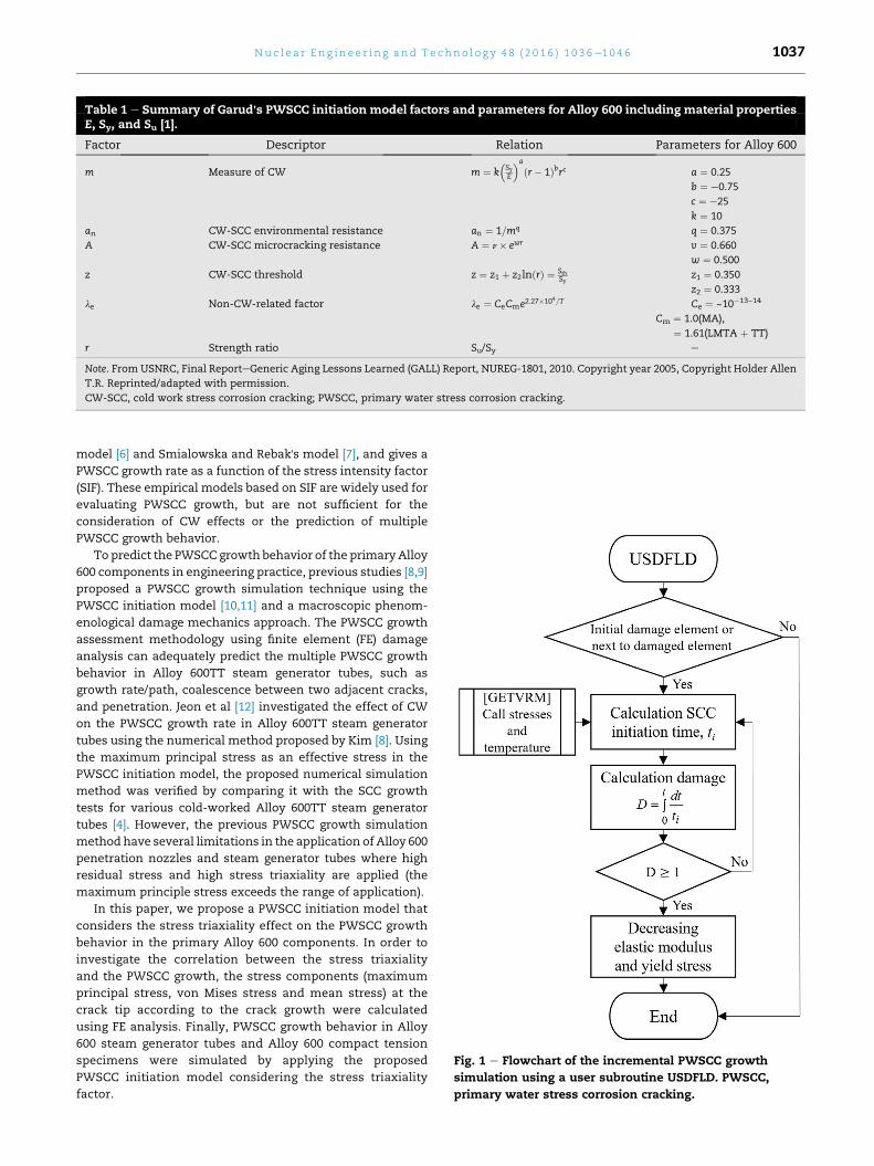
Table 1 e Summary of Garud's PWSCC initiation model factors and parameters for Alloy 600 including material propertiesE, Sy, and Su [1].
Factor Descriptor Relation Parameters for Alloy 600
m Measure of CW m ¼ k�SyE
�a
ðr� 1Þbrc a ¼ 0.25
b ¼ e0.75
c ¼ e25
k ¼ 10
an CW-SCC environmental resistance an ¼ 1=mq q ¼ 0.375
A CW-SCC microcracking resistance A ¼ n� ewr v ¼ 0.660
w ¼ 0.500
z CW-SCC threshold z ¼ z1 þ z2lnðrÞ ¼ SthSy
z1 ¼ 0.350
z2 ¼ 0.333
le Non-CW-related factor le ¼ CeCme2:27�104=T Ce ¼ ~10�13~14
Cm ¼ 1.0(MA),
¼ 1.61(LMTA þ TT)
r Strength ratio Su/Sy e
Note. From USNRC, Final ReporteGeneric Aging Lessons Learned (GALL) Report, NUREG-1801, 2010. Copyright year 2005, Copyright Holder Allen
T.R. Reprinted/adapted with permission.
CW-SCC, cold work stress corrosion cracking; PWSCC, primary water stress corrosion cracking.
Fig. 1 e Flowchart of the incremental PWSCC growth
simulation using a user subroutine USDFLD. PWSCC,
primary water stress corrosion cracking.
Nu c l e a r E n g i n e e r i n g a n d T e c h n o l o g y 4 8 ( 2 0 1 6 ) 1 0 3 6e1 0 4 6 1037
model [6] and Smialowska and Rebak's model [7], and gives a
PWSCC growth rate as a function of the stress intensity factor
(SIF). These empirical models based on SIF are widely used for
evaluating PWSCC growth, but are not sufficient for the
consideration of CW effects or the prediction of multiple
PWSCC growth behavior.
To predict the PWSCC growth behavior of the primary Alloy
600 components in engineering practice, previous studies [8,9]
proposed a PWSCC growth simulation technique using the
PWSCC initiation model [10,11] and a macroscopic phenom-
enological damage mechanics approach. The PWSCC growth
assessment methodology using finite element (FE) damage
analysis can adequately predict the multiple PWSCC growth
behavior in Alloy 600TT steam generator tubes, such as
growth rate/path, coalescence between two adjacent cracks,
and penetration. Jeon et al [12] investigated the effect of CW
on the PWSCC growth rate in Alloy 600TT steam generator
tubes using the numerical method proposed by Kim [8]. Using
the maximum principal stress as an effective stress in the
PWSCC initiation model, the proposed numerical simulation
method was verified by comparing it with the SCC growth
tests for various cold-worked Alloy 600TT steam generator
tubes [4]. However, the previous PWSCC growth simulation
methodhave several limitations in the application of Alloy 600
penetration nozzles and steam generator tubes where high
residual stress and high stress triaxiality are applied (the
maximum principle stress exceeds the range of application).
In this paper, we propose a PWSCC initiation model that
considers the stress triaxiality effect on the PWSCC growth
behavior in the primary Alloy 600 components. In order to
investigate the correlation between the stress triaxiality
and the PWSCC growth, the stress components (maximum
principal stress, von Mises stress and mean stress) at the
crack tip according to the crack growth were calculated
using FE analysis. Finally, PWSCC growth behavior in Alloy
600 steam generator tubes and Alloy 600 compact tension
specimens were simulated by applying the proposed
PWSCC initiation model considering the stress triaxiality
factor.

Table 2 e Material properties and chemical composition of Alloy 600TT SG tube.
Chemical compositions (wt.%) Mechanical properties
C Si Mn P S Ni Cr Fe Cu YS (MPa) UTS (MPa) E (GPa)
0.3 0.29 0.28 0.01 0.001 73.41 15.64 9.51 0.15 328 706 213
Note. From “Evaluation of crack growth rate for alloy 600TT SG tubing in primary and faulted secondary water environments,” by Y. Yamamoto,
M. Ozawa, K. Nakata, T. Tsuruta, M. Sato, T. Okabe, Proc. of the 12th Int. Conf. on Environmental Degradation of Materials in Nuclear Power Sys-
temdWater ReactorsdTMS, 2005, pp. 1243e1252. Copyright year 2005, Copyright Holder Allen T.R. Reprinted/adapted with permission.
Nu c l e a r E n g i n e e r i n g a n d T e c h n o l o g y 4 8 ( 2 0 1 6 ) 1 0 3 6e1 0 4 61038
2. PWSCC assessment methodology
2.1. Garud's CW-SCC initiation model
Garud summarized a technical basis for examining the role
of CW in SCC, and developed an SCC initiation model for
application to an engineering evaluation of SCC initiation
for Ni-based alloy (Alloy 600) and austenitic stainless steel
alloy (Type 304) in primary water conditions [10,11]. In the
model, the duration of SCC initiation is a function of effec-
tive stress, temperature, environmental factors, and mate-
rial strength, including CW effects. The Garud's CW-SCC
initiation model for SCC initiation time, ti, is as follows.
ti ¼ anlelnðAÞln
�A�z
S=Sy�z
�
ln
�A�z1�z
� ; (1)
where an is the CW-SCC environment resistance factor; le is
the non-CW-related factor, including the Arrhenius temper-
ature dependence; A is the CW-SCC microcracking resistance
factor; z is the CW-SCC threshold factor; and S is the effective
tensile stress, including residual stress. Factors and related
parameters of Alloy 600 are summarized in Table 1 in detail. In
the table, T is temperature and E is elastic modulus. Su and Syare ultimate tensile strength and tensile yield strength,
respectively. Ce and Cm are the environment factor and
Fig. 2 e Dimension of Alloy 600TT steam generator tube
specimens [4].
material factor, respectively. Ce can be calibrated by
comparing FE analysis results with PWSCC test data [8,12].
Alloy 600TT, Alloy 600MA, and Alloy 600LTMA refer to ther-
mally treated Alloy 600, mill-annealed Alloy 600, and low-
temperature mill-annealed Alloy 600, respectively.
2.2. PWSCC growth simulation
Because Garud's CW-SCC initiation model uses stress as an
engineering factor, the model is applicable to various types of
loading and can be implemented effectively in FE analysis [10].
In previous studies [8,9], a PWSCC growth simulation method
was developed by applying Garud's CW-SCC initiation model
and the damage mechanics approach [10,11]. As shown in
Fig. 1, an incremental PWSCC growth simulation was per-
formed by using a user subroutine, USDFLD, in ABAQUS [13].
For specified initial damage elements, the SCC initiation time
is calculated by calling stress components and temperature
from a utility routine, GETVRM. In the next step, the damage
(D) was defined as an integral of incremental time (dt) over
SCC initiation time (ti) as follows:
D ¼Z t
0
dtti
(2)
When the accumulated damage becomes unity, an
element is failed by SCC and loses load-carrying capacity by
decreasing yield stress and elastic modulus at the gauss point.
Once an element is damaged, the elements around the
damaged element also start to become damaged.
Table 3 e Dimension of precrack for target initial SIFvalues of SG tube test.
Target initial SIF value (MPa m0.5)
High (15) Medium (12) Low (9)
wi (mm) 0.2
li (mm) 19 15 8
ai/t 0.4 0.3 0.3
Note. From “Evaluation of crack growth rate for alloy 600TT SG
tubing in primary and faulted secondary water environments,” by
Y. Yamamoto, M. Ozawa, K. Nakata, T. Tsuruta, M. Sato, T. Okabe,
Proc. of the 12th Int. Conf. on Environmental Degradation of Materials in
Nuclear Power SystemdWater ReactorsdTMS, 2005, pp. 1243e1252.
Copyright year 2005, Copyright Holder Allen T.R. Reprinted/adapt-
ed with permission.
SIF, stress intensity factor.

Fig. 3 e An FE model of the steam generator tube with a part-through axial crack. FE, finite element.
Nu c l e a r E n g i n e e r i n g a n d T e c h n o l o g y 4 8 ( 2 0 1 6 ) 1 0 3 6e1 0 4 6 1039
3. PWSCC initiation model considering thestress triaxiality effect
Garud's CW-SCC initiation model was developed based on
experimental data of uniform, unnotched samples. There-
fore, effective tensile stress, S, in the model can be the
maximum principal stress or the von Mises stress. In pre-
vious studies [8,9,12], a PWSCC growth simulation technique
using the maximum principal stress has been validated with
the PWSCC growth test for various cold-worked Alloy 600
steam generator tubes. However, when it is applied to actual
problems, using the maximum principal stress has two
problems: (1) it is sensitive to the element size; and (2)
effective tensile stress exceeds the range of application
when high tensile residual stress is applied. To solve these
problems, an additional factor of stress triaxiality was
considered and von Mises stress was used as effective ten-
sile stress in Garud's PWSCC initiation model. The stress
triaxiality factor was derived from a correlation between
crack growth rate (CGR) of PWSCC test results on Alloy 600
steam generator tubes and the stress states at the crack tip
calculated by the FE analysis.
Fig. 4 e True stressestrain curves of Alloy 600TT at 316�Cfor each cold work.
3.1. Published PWSCC experiment on steam generatortube: summary
Yamamoto et al [4] reported the PWSCC growth rate curves
as a function of the SIF for various cold-worked Alloy 600
steam generator tubes with a single axial crack. A tube
specimen was made of the alloy 600TT, and its chemical
compositions and mechanical properties are presented in
Table 2. The dimensions of the original tube specimen
before cold-working are shown in Fig. 2. The tube was
pulled uniaxially to apply CW of 0%, 2%, 5%, 8%, and 18%.
Inside each tube specimen, an axial precrack was electro-
discharge machined (EDM) slit with axial crack lengths of
8 mm, 15 mm, and 19 mm, which correspond to low to high
SIF values. Detailed dimensions of the precrack are shown
in Table 3. A fatigue precrack was introduced at the tip of
EDM silt by cyclic loading with internal pressure of
21.1 MPa. The internal pressure of test loop was kept con-
stant at 21.1 MPa for primary water tests. A simulated
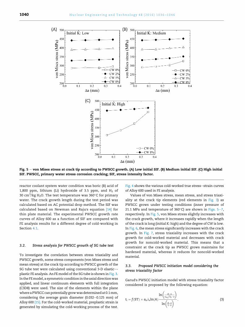
Fig. 5 e von Mises stress at crack tip according to PWSCC growth. (A) Low initial SIF. (B) Medium initial SIF. (C) High initial
SIF. PWSCC, primary water stress corrosion cracking; SIF, stress intensity factor.
Nu c l e a r E n g i n e e r i n g a n d T e c h n o l o g y 4 8 ( 2 0 1 6 ) 1 0 3 6e1 0 4 61040
reactor coolant system water condition was boric (B) acid of
1,800 ppm, lithium (Li) hydroxide of 3.5 ppm, and H2 of
30 cm3/kg H2O. The test temperature was 360�C for primary
water. The crack growth length during the test period was
calculated based on AC potential drop method. The SIF was
calculated based on Newman and Raju's equation [14] for
thin plate material. The experimental PWSCC growth rate
curves of Alloy 600 as a function of SIF are compared with
FE analysis results for a different degree of cold-working in
Section 4.1.
3.2. Stress analysis for PWSCC growth of SG tube test
To investigate the correlation between stress triaxiality and
PWSCC growth, some stress components (von Mises stress and
mean stress) at the crack tip according to PWSCC growth of the
SG tube test were calculated using conventional 3-D elastice-
plastic FE analysis. AnFEmodel of theSG tube is shown inFig. 3.
IntheFEmodel,a symmetric condition intheaxialdirectionwas
applied, and linear continuum elements with full integration
(C3D8) were used. The size of the elements within the plane
whereaPWSCCcanpotentiallygrowwasdeterminedat0.1mm,
considering the average grain diameter (0.032e0.125 mm) of
Alloy 600 [15]. For the cold-worked material, preplastic strain is
generated by simulating the cold-working process of the test.
Fig. 4 shows the various cold-worked true stressestrain curves
of Alloy 600 used in FE analysis.
Values of von Mises stress, mean stress, and stress triaxi-
ality at the crack tip elements (red elements in Fig. 3) as
PWSCC grows under testing conditions (inner pressure of
21.1 MPa and temperature of 360�C) are shown in Figs. 5e7,
respectively. In Fig. 5, von Mises stress slightly increases with
the crack growth, where it increases rapidly when the length
of the crack is long (initial K: high) and the degree of CW is low.
In Fig. 6, themean stress significantly increases with the crack
growth. In Fig. 7, stress triaxiality increases with the crack
growth for cold-worked material and decreases with crack
growth for noncold-worked material. This means that a
constraint at the crack tip as PWSCC grows maintains for
hardened material, whereas it reduces for noncold-worked
material.
3.3. Proposed PWSCC initiation model considering thestress triaxiality factor
Garud's PWSCC initiation model with stress triaxiality factor
considered is proposed by the following equation:
ti ¼ fðSTÞ � anlelnðAÞln
�A�z
seq=Sy�z
�
ln
�A�z1�z
� ; (3)

Fig. 6 e Mean stress at crack tip according to PWSCC growth. (A) Low initial SIF. (B) Medium initial SIF. (C) High initial SIF.
PWSCC, primary water stress corrosion cracking; SIF, stress intensity factor.
Nu c l e a r E n g i n e e r i n g a n d T e c h n o l o g y 4 8 ( 2 0 1 6 ) 1 0 3 6e1 0 4 6 1041
where f(ST) is a stress triaxiality factor, seq is von Mises stress,
and the rest of the factors are the same as those of the con-
ventional model. ti can be determined by the PWSCC growth
data of the SG tube test. The factors of the Garud model
including the vonMises stress can be determined by using the
data shown in Table 1 and the result of the stress analysis.
f(ST) must be equal to 1 in a uniaxial tension state to satisfy
the original model. Based on the stress analysis in the previ-
ous section, f(ST) can be a function of mean stress rather than
stress triaxiality because stress triaxiality in material that has
undergone less cold-work decreases as a crack gets deeper.
The final PWSCC initiation model considering the stress
triaxiality factor can be reexpressed as follows:
ti ¼
8<:1� 1
1þ exp
�� 12
�sm
sUTS;0%þ 0:62
��
9=;anlelnðaÞ
ln
�A�z
seq=Sy�z
�
ln
�A�z1�z
� ;
(4)
where sm is the mean stress and sUTS;0% is the ultimate tensile
strength for noncold-worked material. Fig. 8 shows the f(ST) of
the proposed model as a function of sm=sUTS; 0% for all cases of
stress analysis in Section 3.2. Although symbols are largely
dispersed in the graph, the correlation between the stress
triaxiality factor and themean stress effect on PWSCC initiation
time is well defined by the proposed PWSCC initiation model.
4. Validation of proposed pwscc initiationmodel
4.1. PWSCC growth simulation of steam generator tubetest
The PWSCC growth simulation of the SG tube test was per-
formed by applying the proposed PWSCC initiation model
considering the stress triaxiality factor. TheFEmodel inFig. 3 is
the same for all PWSCC growth simulations. To determine the
final value of environment factor Ce, FE damage analyses were
performed for various environment factor values, and results
of the analysis were compared with a fracture surface for 5%
cold-worked material with a low initial SIF, which is shown in
Table 3. Fig. 9 shows the calibration result of environment
factorCe by comparing fracture surfaces of the experiment and
the prediction using FE damage analysis. The final value of Ce
was determined via this process to be 4.9 � 10�14.
Fig. 10 shows a comparison of PWSCC growth rate versus
SIF for Yamamoto's test and the FE result. SIFs were calculated

Fig. 7 e Stress triaxiality at crack tip according to PWSCC growth. (A) Low initial SIF, (B) Medium initial SIF and (C) High initial
SIF. PWSCC, primary water stress corrosion cracking; SIF, stress intensity factor.
Fig. 8 e Stress triaxiality factor of a proposed PWSCC
initiation model. PWSCC, primary water stress corrosion
cracking.
Nu c l e a r E n g i n e e r i n g a n d T e c h n o l o g y 4 8 ( 2 0 1 6 ) 1 0 3 6e1 0 4 61042
based on Newman and Raju's equation [14] for thin plate
materials, as presented in Yamamoto et al's paper [4]. Symbols
indicate Yamamoto et al's test data. Solid lines indicate those
derived by curve-fitting Yamamoto et al's test results by using
Scott equation [4]. The dotted lines are FE damage analysis
results. In Yamamoto et al's test results, there is a little dif-
ference in CGR between 0% and 2% cold-worked materials.
However, in PWSCC growth simulation, cold-working effects
are considered, and analysis results show a difference in CGR
between cold-worked materials. For this reason, FE results of
0% and 2% cold-worked materials show some differences
compared to the test data and Scott's equation, whereas the FE
results of 5% and 8% cold-worked materials agree well with
experimental results.
4.2. PWSCC growth simulation of compact tension test
To validate the proposed model, PWSCC growth simulations
of a compact tension test were performed. The Korea Atomic
Energy Research Institute carried out a PWSCC test for
compact tension specimens extracted from an Alloy 600 rod
[16]. A compact tension (CT) specimen is subject to constant
loading conditions, and the value of SIF is 30 MPa m0.5 at the
crack tip under primary water reactor conditions of 325�C. Thevalues of yield strength and ultimate tensile strength of the
Alloy 600 rod are 241 and 552MPa, respectively. An FEmodel is

Fig. 9 e Comparison of the fracture surface for Yamamoto's SG tube test with the prediction using the PWSCC growth
simulation to calibrate environment factor Ce. PWSCC, primary water stress corrosion cracking.
Nu c l e a r E n g i n e e r i n g a n d T e c h n o l o g y 4 8 ( 2 0 1 6 ) 1 0 3 6e1 0 4 6 1043
presented,wherein dimensions of the CT specimen are shown
in Fig. 11A and the detailed mesh geometry at the crack tip is
shown in Fig. 11B. Conditions and procedures of the damage
FE analysis are the same as those in the SG tube simulation.
Fig. 12 shows a comparison in the fracture surface of the CT
specimen after 278 days between the experiment and the
prediction using FE damage analysis with a calibrated value of
Ce (¼1.65 � 10�14).
Fig. 10 e Comparison of PWSCC growth rate versus SIF for the v
Yamamoto et al's test data and the curve fitting. (A) Noncold wor
(D) Degree of cold work 8%. PWSCC, primary water stress corro
Fig. 13 shows the PWSCC growth results from FE simula-
tion. CGRs were determined by differentiating fitting lines of
the PWSCC growth results in Fig. 13A, and SIF was calculated
based on the standard method in ASTM [17]. Fig. 13B shows
the analytic PWSCC growth rate results as a function of SIF
with the PWSCC growth rate curve in ASME code, Sec XI, App.
O [5]. The prediction of PWSCC growth behavior using FE
analysis shows a good agreement with that of the ASME code.
arious cold work degrees and initial SIF values between the
ked. (B) Degree of cold work 2%. (C) Degree of cold work 5%.
sion cracking; SIF, stress intensity factor.

Fig. 11 e A FE model of the Alloy 600 compact tension test. (A) Dimension of the CT specimens. (B) Detailed mesh geometry
at the crack tip. CT, compact tension; FE, finite element.
Nu c l e a r E n g i n e e r i n g a n d T e c h n o l o g y 4 8 ( 2 0 1 6 ) 1 0 3 6e1 0 4 61044
For a CT test, Fig. 14A shows the analytic PWSCC growth
behavior of the proposed PWSCC initiation model considering
the stress triaxiality factor (effective tensile stress, S ¼ von
Fig. 12 e Comparison of the fracture surface of the CT
specimen after 278 days between the experiment and the
prediction using FE damage analysis using calibrated value
of Ce (¼1.65 £ 10¡14). CT, compact tension; FE, finite
element.
Mises stress). Furthermore, analytic PWSCC growth results of
the original Garud's CW-SCC initiation model using von Mises
stress and the maximum principal stress as the effective
tensile stress are shown in Figs. 14B and 14C, respectively. As
shown in Fig. 14, the proposed PWSCC initiation model
considering the stress triaxiality factor is the most suitable for
simulating PWSCC growth behavior.
5. Conclusions
In this study, a PWSCC initiation model considering the stress
triaxiality factor of Alloy 600 was proposed in order to conduct
a PWSCC growth simulation based on the macroscopic
phenomenological damage mechanics approach. The
following conclusions were drawn:
� Using the maximum principal stress as the effective ten-
sile stress as in Garud's PWSCC initiation model has
several limitations when it is applied to PWSCC growth
simulation.
� A stress triaxiality effect on PWSCC initiation should be
additionally consideredwhen using vonMises stress as the
effective tensile stress of Garud's model.
� A stress triaxiality factor can be a function of mean stress
rather than stress triaxiality.

Fig. 13 e PWSCC growth results of the Alloy 600 compact
tension specimen from the FE simulation. (A) PWSCC
growth curve versus time. (B) PWSCC growth rate as a
function of SIF with the PWSCC growth rate curve in ASME
code, Sec XI, App. O. ASME, American Society of
Mechanical Engineers; FE, finite element; PWSCC, primary
water stress corrosion cracking. SIF, stress intensity factor.
Fig. 14 e Analytic PWSCC growth behavior of Alloy 600
compact tension specimen. (A) proposed PWSCC initiation
model considering stress triaxiality factor (the effective
tensile stress, S ¼ von Mises stress). (B) Original Garud'sPWSCC initiation model (S ¼ the von Mises stress). (C)
Original Garud's PWSCC initiation model (S ¼ the
maximum principal stress). PWSCC, primary water stress
corrosion cracking.
Nu c l e a r E n g i n e e r i n g a n d T e c h n o l o g y 4 8 ( 2 0 1 6 ) 1 0 3 6e1 0 4 6 1045
� PWSCC growth simulations using the proposed PWSCC
initiation model considering stress triaxiality factor can
predict the PWSCC growth test results of different types of
cold-worked Alloy 600 steam generator tubes and compact
tension specimens.
� PWSCC growth simulations will be performed for actual
problems expected to occur in the PWR: (1) Alloy 600
penetration nozzles in the reactor pressure vessel; and (2)
an Alloy 600 steam generator tube at the top of tube sheet
where high residual tension stress and prestrain are
applied.
Conflicts of interest
The authors declare no conflicts of interest.
Acknowledgments
This work was supported by the Nuclear Energy Technology
Innovation Program of the Korea Institute of Energy Tech-
nology Evaluation and Planning (KETEP) grant funded by the
Korea governmentMinistry of Trade, Industry and Energy (No.
2012T100100443). This work was supported by the Nuclear
Power Core Technology Development Program of the Korea
Institute of Energy Technology Evaluation and Planning
(KETEP), granted financial resource from theMinistry of Trade,
Industry & Energy, Republic of Korea (No. 20131520000140).
r e f e r e n c e s
[1] USNRC, Final ReportdGeneric Aging Lessons Learned (GALL)Report, NUREG-1801, 2010.
[2] W.C. Moshier, C.M. Brown, Effect of cold work andprocessing orientation on stress corrosion cracking behaviorof Alloy 600, Corrosion 56 (2000) 307e320.

Nu c l e a r E n g i n e e r i n g a n d T e c h n o l o g y 4 8 ( 2 0 1 6 ) 1 0 3 6e1 0 4 61046
[3] R. Bandy, D. van Rooyen, Stress corrosion cracking of InconelAlloy 600 in high temperature water-an update, Corrosion 40(1984) 425e430.
[4] Y. Yamamoto, M. Ozawa, K. Nakata, T. Tsuruta, M. Sato,T. Okabe, Evaluation of crack growth rate for alloy 600TTSG tubing in primary and faulted secondary waterenvironments, in: Proc. of the 12th Int. Conf. onEnvironmental Degradation of Materials in NuclearPower SystemdWater ReactorsdTMS, 2005, pp.1243e1252.
[5] ASME, ASME Boiler & Pressure Vessel Code, Section XI. Rulesfor Inservice Inspection of Nuclear Power Plant Components,2007.
[6] P.M. Scott, An analysis of primary water stress corrosioncracking in PWR steam generators, in: Proc. of the SpecialistsMeeting on Operating Experience with Steam Generators.Brussels, Belgium, 1991, pp. 5e6.
[7] Z.S. Smialowska, R.B. Rebak, Stress corrosion cracking ofalloy 600 in high-temperature aqueous solutions: influencingfactors, mechanisms and models, in: Proc. of Conf. onControl of Corrosion on the Secondary Side of SteamGenerators, Airlie, VA, 1995, pp. 223e257.
[8] J.S. Kim, E.J. Heo, J.Y. Jeon, Y.J. Kim, n investigation onmultiple axial surface PWSCC growth behaviors inprimary Alloy 600 components using the PWSCCinitiation model and damage mechanics approach, in:Proceeding of the ASME 2014 Pressure Vessels and
Piping Conference, PVP2014e28517, Anaheim, California,2014.
[9] J.Y. Jeon, Y.J. Kim, J.S. Kim, Multiple axial surface PWSCCgrowth assessment of steam generator tube using thePWSCC initiation model and damage mechanics approach,Procedia Mater. Sci. 3 (2014) 811e816.
[10] EPRI, Stress Corrosion Cracking Initiation Model for StainlessSteel and Nickel Alloys, EPRI TR-1019032, 2009.
[11] EPRI, Validation of Stress Corrosion Cracking Initiation Modelfor Stainless Steel and Nickel Alloys, EPRI TR-1025121, 2012.
[12] J.Y. Jeon, Y.J. Kim, J.S. Kim, Computational simulation of coldwork effect on PWSCC growth in Alloy 600TT steamgenerator, J. Mech. Sci. Technol. 30 (2016) 689e696.
[13] ABAQUS, ABAQUS Standard/User's Manual, Version 6.13,Dassault Systemes Inc., 2011.
[14] J. Newman, I. Raju, Stress-Intensity Factor Equations forCracks in Three-Dimensional Finite Bodies Subjected toTension and Bending Loads, NASA Technical Memorandum,85793, 1984.
[15] H.S. Chung, H.D. Kim, Y.J. Oh, J.H. Baek, Y.P. Kim, A review onthe ODSCC of steam generator tubes in Korean NPPs, Nucl.Eng. Technol. 45 (2011) 513e522.
[16] S.S. Hwang, Y.S. Lim, S.W. Kim, D.J. Kim, H.P. Kim, Role ofgrain boundary carbides in cracking behavior of Ni baseAlloys, Nucl. Eng. Technol. 45 (2013) 73e80.
[17] ASTM, Standard test method for measurement of fracturetoughness, E1820e13.