Embed Size (px)
Citation preview

1
Axisymmetric whole pin life modelling of advanced gas-cooled reactor nuclear fuel
R. Mella(a) and M. R. Wenman(a*)
(a) Department of Materials, Imperial College London, London, SW7 2AZ
(a*) Corresponding author: Tel +44 (0)207 5946763 E-mail: [email protected]
Abstract
Thermo-mechanical contributions to pellet-clad interaction (PCI) in advanced gas-cooled
reactors (AGR) are modelled in the ABAQUS finite element (FE) code. User supplied sub-
routines permit the modelling of the non-linear behaviour of AGR fuel through life. Through
utilization of ABAQUS’s well-developed pre- and post-processing ability, the behaviour of the
axially constrained steel clad fuel was modelled. The 2D axisymmetric model includes thermo-
mechanical behaviour of the fuel with time and condition dependent material properties. Pellet
cladding gap dynamics and thermal behaviour are also modelled. The model treats heat up as a
fully coupled temperature-displacement study. Dwell time and direct power cycling was applied
to model the impact of online refuelling, a key feature of the AGR. The model includes the visco-
plastic behaviour of the fuel under the stress and irradiation conditions within an AGR core and
a non-linear heat transfer model. A multiscale fission gas release model is applied to compute
pin pressure; this model is coupled to the PCI gap model through an explicit fission gas
inventory code. Whole pin, whole life, models are able to show the impact of the fuel on all
segments of cladding including weld end caps and cladding pellet locking mechanisms (unique
to AGR fuel). The development of this model in a commercial FE package shows that the
development of a potentially verified and future-proof fuel performance code can be created
and used.
Keywords: Fuel Performance, ABAQUS, Finite Element, AGR
1.0 Introduction
1.1 Pellet-cladding interaction
Numerous authors have investigated the phenomenon of PCI in the past [1–10]. These studies
have included the AGR system. The AGR studies from the early 90s offer insight into the
effective bonding forces between AGR cladding and fuel, albeit that these studies were for a very
simplified geometry and material properties. Walker’s models were two dimension r-q
segments of a pellet and cladding in a coupled thermo-mechanical transient analysis. This
analysis showed that the expected bond between pellet and clad will fail and cause the
debonding of about 6% of the pellet-clad surface producing sufficient stress relief to prevent
further debonding. Walker also shows that a failure of this size was sufficient to cause a two
orders of magnitude reduction in the number of pellet cracks to propagate in the adjacent
cladding. Most work in recent years has focussed on water cooled systems [2-3, 11-13]. Marchal
[11] showed through 3D modelling of PCI, in the CAST3M FE code, that the while pellet fracture
did produce stress concentrations in the cladding there was also a significant stress remaining
in the fuel fragment. These pellet fragments had sufficient remaining stresses that later
interaction with the cladding through friction contact produced further radial cracking.
Marchal’s smeared crack model emphasises the non-linear behaviour of PCI cracking and that it
is strongly dependent on fuel-cladding friction.
*Manuscript
Click here to view linked References

2
Very recently attempts have been made to use more openly available commercial FE codes to
model fuel performance [12], this was to serve as a test bed for a custom fuel performance
model [13]. Williamson modelled the PWR system using an axisymmetric model and showed
the cladding stresses for PWR fuel can be computed. With modification the model was capable
of including thermal-mechanical behaviours of the highly non-linear material responses, which
contribute to the fuel pin response. Williamson’s model included effects of fission gas release
and its impact on pin pressure. Capable of both steady state and transient studies displaying an
ability to match the capabilities of current fuel performance codes in commercial modelling
packages.
A whole variety of bespoke fuel performance codes are also available spanning different
numbers of dimensions [14] and also often specialising in steady state event modelling (e.g.
FRAPCON [15] and COMETHE) problems or transients (e.g. FRAPTRAN[16] and TRANSURANUS
[17]) whilst others give overall pin performance for long timescales. ENIGMA, for example, is
intended for the analysis of normal operation and frequent faults [18]. Many of the fuel
performance codes also rely heavily on empirical data and as such are not necessarily able to
predict well events outside of the envelope for which they were created. A good example that
illustrates this was the FUMEX-II research project on fuel behaviour predictions at high burn-up
[19]. The experiment showed the varied results obtained by many fuel performance codes
trying to predict the same problem when designed for different fuel types and problems, arising
from data gaps especially at high burn-up, and different fitting approaches on empirical data.
One way to get around this is to try, where possible, to make fuel performance codes based on
physical laws rather than empirically derived data making them as mechanistic as possible.
Similarly to Williamson this was the aim of this work albeit for the case of modelling PCI in AGR
fuels. Furthermore, the objective was to try to use ABAQUS, which now has enough features to
allow a good representation of many of the needed phenomena, such as heat transfer, diffusion,
gap elements etc to deal with the complicated problems of fuel performance. Presented within
this paper is a coupled fuel-gap-clad heat transport axisymmetric whole pin model for the AGR.
1.2 The AGR system
The AGR core contains about 300 fuel stringers. Each stringer contains seven or eight 1 m long
sub-assemblies containing 36 steel clad fuel pins. Fuel pins consist of stainless steel tubes made
from Nb stabilised austenitic stainless steel (25 wt% Ni, 20 wt% Cr, 0.05 wt% C and 0.5 wt%
Nb) containing about 64 annular UO2 ceramic pellets enriched in 235U by several per cent. Due to
the relatively high temperatures of 650°C – 700°C and overpressure (4MPa) of the CO2 coolant
in the core, the cladding creeps down until initial contact with the pellet occurs. This happens
very early in life (over a timescale of days to weeks) compared to the behaviour of PWR fuel and
is in part a consequence of the fast cladding creep rate, at the high operating temperature, and a
smaller initial pellet cladding gap (20 µm) than that of a PWR. In the case of a power increase
this PCI can induce large stresses in the cladding that might lead to fuel pin failure. It is
therefore necessary to be able to understand the occurrence of PCI failure. The AGR fuel also
does not have the capacity to freely expand during power ramping as there is no plenum at the
top of the fuel pins. As the fuel temperature ramps up the thermal expansion of the pellets
stretches the steel cladding to accommodate the increase in length. In order to ensure a near
uniform strain along the axial length of the fuel pin the cladding is deformed into grooves,
known as anti-stacking grooves (ASG), manufactured into some of the pellets. The cladding is

3
formed into these ASGs at manufacture to lock together approximately five pellet groups and
this helps prevent large gaps forming in the fuel stack due to the pellets restacking (see, Fig. 1).
Since the year 2000 there have been several fuel failures potentially attributable to PCI in
various AGR reactors [20]. When radioactivity in the coolant gas indicates that fuel in the
reactor may have failed, the operators have to follow a procedure that may involve reducing
reactor power or shutting it down. The potential costs include: replacement for generation loss,
non-optimum use of fuel and increased fuel disposal costs as failed fuel cannot be disposed of by
the normal route. These include: reduction in reactor power, not refuelling on-load (a feature of
the AGR system) and not shuffling fuel (to improve utilisation). FE simulations shown here are
used to help in interpreting experiments and ultimately to develop efficient fuel codes, core
protections and PCI resistant designs.
2.0 Model development
The choice of an axisymmetric model permits the modelling of an entire AGR fuel pin through
life. The pin was assumed to be axially symmetric about its centre to reduce computation time.
The model pin contains 32.5 pellets of various geometries and materials. The grooved locking
pellets are introduced every five conventional pellets, and the cladding is collapsed into the
ASGs producing regions where the pellets are mechanically locked together. Before the pin end
caps there is a third type of pellet, an alumina (Al2O3) spacer pellet. The alumina pellets act
primarily as a thermal insulator for the fuel pin end caps and welds.
To carry out these studies the commercial FE package ABAQUS [21] was used. The major focus
of this study was the use of the ABAQUS/Standard implicit code solving initially a transient
coupled heat and displacement problem to accurately model heat up behaviour of the fuel pin.
The model was then solved in the steady state for long term effects such as creep and any direct
power cycling to simulate the online refuelling was solved in transients in order to study the
impact on the AGRs cladding stresses. Implicit numerical methods and sophisticated iteration
and time integration error control permit simulation of steady reactor operation, or very rapid
transients.
Each pellet was constructed from quadrilateral linear axisymmetric coupled temperature and
displacement elements, the cladding is modelled with linear triangular elements allowing for
adaptive remeshing in ABAQUS (quadrilateral elements are unsupported in automatic adaptive
remeshing). The mesh of the pellets and cladding are shown in Fig. 2. The size of element within
each pellet ranges from 150 µm to 200 µm. The steel cladding was meshed consistently with
elements of the same type but element sizes ranged from 50 µm to 20 µm. Mesh sensitivity in
the cladding was addressed by the use of adaptive remeshing with a minimum element size of 1
µm and 3 ABAQUS error indicators: Mises equivalent stress, equivalent plastic strain and the
creep strain. Meshes containing elements below 50 µm produced only small errors in the stress
of the order of several hundred Pa. Final remeshing was manual from observation of error
indicators. Manual remeshing was used as surface elements, which are required for modelling
the fuel pin as a fluid filled cavity, are not supported in an automatic remeshing procedure
(ABAQUS 6.10).
The reduced dimensions of the axisymmetric model permit a higher element density when
compared to a 3D fuel model; for the cladding a characteristic element size of less than 50 µm

4
was used. Even at this high mesh density a model spanning large timescales was possible. A
whole five year fuel dwell time was modelled on a single core workstation in a matter of an
hour. The model was scaled to years of fuel pin life. Despite the complex contact that may occur
during ramping an implicit FE method was used (ABAQUS/Standard) with adaptive time
stepping. A minimum time step of 10 µs and a maximum of 10 days were used; the upper limit
on time stepping was large because of the ability to sub-cycle the fission product inventory and
fission gas release models. After a one week heat-up to full volumetric power of 125 MW/m3
the fuel was held at this power for one year, followed by the application of power cycles (3
cycles between 30% to 70%) to the fuel pin to model online refuelling, this operation was
preceded by a power spike to 150% volumetric power. Finally, the fuel was modelled in a
steady state manner at 100% power for the remainder of a 5 year dwell time (see, Fig. 3 for load
history). The overall model parameters are given in Table 1.
2.1 Gap and contact models
The clad-pellet gaps variable nature requires a model that couples the mechanics of the fuel
pellet and cladding with a model for the gas gap. Material models are applicable at early life and
extensible to late life operation. ABAQUS includes robust contact algorithms applicable to
arbitrary geometry, essential for capturing all the complexity of multidimensional pellet-pellet
or PCI contact.
Heat transport between the different surfaces within the fuel pin was implemented by use of
gap elements with properties defined by the URGAP model [22,23] assuming that at early life
the cladding inner and fuel outer surfaces are quite smooth (0.8-2 µm surface roughness). For
late life a coupled fission gas release and fission gas inventory model is used to compute gas
content and this is also implemented in ABAQUS. This internal model supplies the appropriate
fractions of filling gas (helium, krypton and xenon) in order to compute gap conductivity. The
external pin surfaces are modelled by a gas film representing turbulent flow of the CO2 coolant,
with a sink temperature, which increases linearly over heat up time from 650°C to the expected
outlet temperature of the AGR of approximately 700°C.
2.1
2.2
1/2
2 f c
press s
f cl
k k Ph C
k k Hd=
+
2.3
, , , ,
A B
k k k kkd p T T
¶ ¶ ¶ 
¶ ¶ ¶ 
2.4
The URGAP model includes different heat transfer mechanisms as the sum of their heat transfer
coefficients (radiative, , gas conduction, , of filling gas and pressure enhanced heat
transfer, expressed in equations 2.1 – 2.3). Where and are the fuel, filling gas
and cladding thermal conductivity respectively. Where and are the fuel and
cladding accommodation length; fuel and cladding mean roughness and the gap thickness

5
respectively. , P, and H are the surface contact fraction (taken as 1 as
recommended from a fit to measurements [24]), contact pressure, temperature on fuel outer
surface, temperature on inner cladding surface and cladding hardness respectively. The
appropriate gas fraction mixing weighting factors were calculated according to Lindsay and
Bromley [25].
The ABAQUS implementations of these interactions are in a GAPCON user sub-routine. This sub-
routine takes as input the Jacobian matrix of the heat transfer contributions, which are to be
included into the system matrix, which describes the thermal interactions between a slave
surface node and a master surface node. By supplying ABAQUS with Jacobian matrix
contributions (see equation 2.4), of changes of thermal conductivity with respect to surface
clearance, contact pressure and the surface temperatures, a converged solution of thermal flux
is more easily found. The radiative contributions were computed with ABAQUS’s standard gap
radiation toolset as accurate radiative calculations require view factor information not supplied
in the GAPCON interface.
Mechanical contact, normal to a surface, is modelled as hard contact enforced though the
penalty method, with separation permitted after contact, and the tangential mechanical contact
behaviour is modelled as Coulombic friction where the steel/UO2 coefficient of friction, µ is 0.8.
The thermal and mechanical interaction was used to define contact in pellet-pellet and pellet
clad events. When modelling the fuel bonded to the cladding, the fuel and cladding are not
permitted to separate (normal no separation contact constraint) and the tangential behaviour is
a rough contact condition.
The filling gas pressure is modelled as a surface pressure arising from modelling the interior of
the fuel pin as a “fluid” filled cavity, with hydrostatic boundary conditions, where the gas is a
user defined volume. The free volume of the fuel pin is calculated from the evaluation of the
internal pressure and this is found from the total pin volume minus the volume of each pellet.
The process by which this is implemented in ABAQUS is through defining the surface encasing a
pellet as a fluid filled vessel. This surface deforms with the surface nodes of the pellet changing
volume with swelling and thermal expansion. Similarly the internal surface of the pin cladding is
defined as the boundary of a fluid filled vessel, subtracting the pellet volumes from the total pin
volume we have the pin free volume as a function of both pellet and cladding deformation. The
pressure is defined by the inner pellet radius temperature and gas content as dictated by the
fission gas release routines. Released fission gas is treated as an ideal gas.
The fuel pins exterior pressure is modelled as a simple surface pressure dictated by CO2 coolant
pressure approximated in the AGR core, which varies with external coolant temperature,
permitting a complete model of fuel pin behaviour under normal and accident conditions while
minimising assumptions on the boundaries of the computational domain.
2.2 RADAR model
In order to model long life behaviour of nuclear fuel considerations must be made towards
power profiles. As nuclear fuel burns-up the 235U content reduces and some of the fertile 238U
transmutates to various plutonium isotopes (particularly at the edge of the fuel pellet where the
fastest flux exists). ABAQUS currently lacks the ability to compute neutron diffusion, to evaluate
the flux for inventory change, and as there is power rating influence on species diffusion, in
reality, ABAQUS cannot evaluate a many species diffusion-thermo-mechanical problem in a

6
coupled manner. To solve in ABAQUS would require custom elements or a small step iterative
solution procedure.
The flux, power depression factors and uranium content was evaluated on a 2D uniform finite
difference grid of similar dimensions to the fuel pin. RADAR [26] [27] is then explicitly time
stepped forward (sub-cycled with respect to the larger time step of the implicit thermo-
mechanical simulation), the RADAR models grid was kept much finer than the rest of the model,
to reduce error, when linear projection was used to transfer the scaled volumetric power from
RADAR to the rest of the model. The fuel burn-up serves as an important parameter for fission
gas generation, fuel swelling and the changes in fuel thermal conductivity.
2.3 Pellet fracture model
Whilst most fuel behaviour can be accurately captured by 2D models, there are many features
that require a full 3D model. One very important feature is the pellet cracking, which has two
strong effects: one is fragment relocation and the other is an effect of the relaxation of the
stresses and strains within each fragment [28]. The stresses within intact pellets and a cracked
pellet can vary greatly [29]. Most axisymmetric models consider thermal loading comparable to
those found within reactor. Therefore it is important that the model accounts for fragmentation
and relocation as these effects will reduce the time to pellet cladding contact [30]. Some
attempts have been made to model fracture in 3D pellets using cohesive zones to understand
the pellets fractured stress state [31]. The relocation of pellet segments can be treated
empirically and the relaxation of stresses can be treated through a modification of the material
mechanical laws. Stress relaxation effects have been implemented in this model by the
modification of the materials characteristics. Two different implementations of the material
modification can be made: the material is treated as isotropic but with modified material
properties or by replacing the material law with an anisotropic material model. The isotropic
case proposed by Jankus and Weeks [32] was to consider an isotropic material where both the
Young’s modulus and the Poisson’s ratio of the cracked material have been changed assuming
the cracks were perpendicular to the fuel axis. The modified Young’s modulus (cE ) and
Poisson’s ratio ( cn ) can be found from equations 2.5 and 2.6 where N is the number of cracks.
2
3
N
cE Eæ ö
= ç ÷è ø
2.5
1
2
N
cn næ ö
= ç ÷è ø
2.6
This modified isotropic behaviour was selected for its simplicity, and also permits modifications
to allow cracked fuel to creep faster (see equation 2.7 where m is the stress exponent from the
thermal creep, is the equivalent plastic strain rate).
( 1)3
2
N m
c
p pe e-
æ ö= ç ÷
è ø
c
p pe ec
p pp p
æ ö3ç ÷æ öæ ö3ç ÷ç ÷
2
2.7
2.4 Fission gas release

7
In a similar approach to [12] the fuel pin is treated as a fluid filled capsule, where the
temperature of the fluid is determined by the average fuel surface temperature. The fluid within
the pin changes with time and is modified from a user supplied sub-routine. The sub-routine
computes the current thermal profile of the fuel and a Booth diffusion step is performed on
virtual spherical grains [33]. The amount of fission gas released from a single grain for a
particular radial distance is computed and repeated for every material point in the fuel. The
value found is then integrated over the entire volume of the fuel and the fission gas released is
added to the filling gas (See Fig. 4). The filling gas is treated as a mixture of helium, xenon and
krypton. The thermal profile of the fuel and fuel surface temperatures are extracted from the FE
simulation, the average of the fuel surface temperature was used [34]. This simple thermal
model coupled to a fission gas diffusion model embedded within an ABAQUS routine shows the
extensibility of ABAQUS and permits ever more accurate simulation of nuclear fuel.
More complex fission gas models have also been implemented with this model. These are
capable of approximating diffusion of fission gas in the grains; trapping of gas at the grain
boundaries; trapping in bubbles and simultaneously modelling the diffusion of the bubbles.
This was accomplished by the use of a 1D FE model solving the coupled intragrannular grain
atom diffusion and bubble diffusion partial differential equations (of the form of equations 2.8
and 2.9) outlined in [35]. It is assumed these equations can be coupled by the fuels trapping and
resolution parameters (implemented in TRANURANUS). This 1D FE model is solved at all fuel
material points to approximate the total fission gas generation and release rate. This shows that
an ABAQUS fuel performance code may incorporate multiple length scales, and an arbitrary
number of models can be evaluated at all material points.
2.8
2.9
Where and are the in-solution gas concentration and the concentration of bubbles
respectively. The parameters that govern motion are the diffusion coefficients and for
atoms in solution and bubbles, , and are the gas trapping, resolution and gas generation
parameters respectively. Using the heterogeneous model for resolution, and that the trapping
rate is diffusion controlled, with a dilute trapping density, the values for all fission gas release
models parameters used in this study were computed from equations 3-6 in [35]. In the model
outlined by van Uffelen et al. [35] insights from molecular dynamics studies were used to study
the resolution parameter, making the implementation of this fission gas release model a
multiscale enhancement for a FE fuel performance code.
2.5 Fuel and cladding material properties
The UO2 fuel thermal behaviour is outlined in Table 2, showing the great number of non-
linearities to be modelled by ABAQUS in the processes of simulating whole pin life. Table 3
shows many of the mechanical properties of the cladding, accounting for non-linear effects such
as swelling, also included is a breakdown of how fuel creep was modelled.
A model to describe the fuel mechanical behaviour during power ramps is now presented.
These mechanical properties are descriptive of the fuel elastic properties and its creep and
swelling as a consequence the fuel in this model can be considered a visco-plastic material. The
material properties for the visco-plastic behaviour of the fuel were extracted from the MATPRO

8
Material Library [36] that account for radiation induced; high stress and low stress creep (as
defined in Table 2) with temperature and irradiation dependence.
3.0 Results and discussion
3.1 Thermomechanics
Fig. 5 shows a power ramp of new fuel from a shutdown state to 150% volumetric power. This
ramp is designed purely to demonstrate the present modelling developments and is not
representative of normal AGR operation. The cladding elongates to accommodate the increase
in size of the fuel pellets due to thermal expansion. Despite small local plastically deformed
regions forming around the locking pellet the extension of the whole fuel pin maintains a very
close to linear relation of elongation to volumetric power. Local plastic strain in these locking
regions is initially confined to several elements at the contact surface. On large ramps applied to
the fuel the plastic region extends to the cladding outer surface.
Figs 6 and 7 characterise thermal behaviour of the fuel during heat up and power ramping. Axial
variation from 1D models arise from the ASG pellets and the cladding. Fig. 6 shows the impact
of fuel burn-up on the fuel centreline temperature. The centre temperature increases
approximately 130°C over fuel life. Fig. 7 shows five standard pellets separated between a pair
of locking pellets; the locking region shows a reduction in fuel centreline temperature compared
to a standard pellet as a consequence of a reduced fuel radius and greater contact pressure with
the cladding. While there was an increase of 130°C in the fuel centreline temperature, over fuel
life, a smaller increase of just 20°C was observed for the cladding. The fuel centreline
temperature changes observed are mostly a consequence of the reduction in the thermal
conductivity of the fuel due to fuel burn-up.
Fig. 8 shows the cladding radial displacements throughout the simulated fuel pellet life. The
displacement plot shows that, in the specific instance modelled, the creep down of the cladding
onto the fuel occurs at about 310 days (6 GWd/tU burn-up). The displacement of the cladding
increases radially as the fuel swells after contact and clad creep down. The increase in stress in
the cladding, induced by pellet swelling, develops too slowly with respect to the high cladding
creep rate to permit the development of plastic strain under normal operating conditions.
Therefore the large radial displacements observed in the cladding are produced from creep
strain, confirming the source of cladding damage from long term normal operation is from creep
damage/ductility exhaustion. The displacement plots show the cladding radial displacements.
Contact of the pellet and cladding triple point, here we define a triple point as the region where
two adjacent pellet ends intersect the cladding, as an initial sharp outward displacement and as
the thermal expansion and swelling of the fuel continues the triple point increases its outward
movement and the cladding is deformed about the pellets vertices.
At the very start of life a 30 micron expansion of the cladding occurs. This is due to the pre-
heating of the reactor core to 350°C. This fuel pin pre-heating causes the filling gas (ideal gas) to
expand. There is also an over prediction of the gas temperature as the gas takes on the
temperature consistent with the pellets centreline temperature. Also as the fuel begins heat
generation the cladding thermally expands with an expansion of over twice that of the fuel. It is
noted that there is an initial condition sensitivity, with regards to the selected gas temperature,
as to when the cladding has completely collapsed on to the pellets.
9
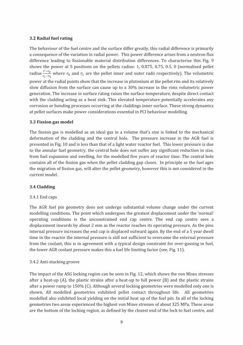
3.2 Radial fuel rating
The behaviour of the fuel centre and the surface differ greatly, this radial difference is primarily
a consequence of the variation in radial power. This power difference arises from a neutron flux
difference leading to fissionable material distribution differences. To characterise this Fig. 9
shows the power at 5 positions on the pellets radius: 1, 0.875, 0.75, 0.5, 0 (normalised pellet
radius where and are the pellet inner and outer radii respectively). The volumetric
power at the radial points show that the increase in plutonium at the pellet rim and its relatively
slow diffusion from the surface can cause up to a 30% increase in the rims volumetric power
generation. The increase in surface rating raises the surface temperature, despite direct contact
with the cladding acting as a heat sink. This elevated temperature potentially accelerates any
corrosion or bonding processes occurring at the claddings inner surface. These strong dynamics
at pellet surfaces make power considerations essential in PCI behaviour modelling.
3.3 Fission gas model
The fission gas is modelled as an ideal gas in a volume that’s size is linked to the mechanical
deformation of the cladding and the central hole. The pressure increase in the AGR fuel is
presented in Fig. 10 and is less than that of a light water reactor fuel. This lower pressure is due
to the annular fuel geometry, the central hole does not suffer any significant reduction in size,
from fuel expansion and swelling, for the modelled five years of reactor time. The central hole
contains all of the fission gas when the pellet cladding gap closes. In principle as the fuel ages
the migration of fission gas, will alter the pellet geometry, however this is not considered in the
current model.
3.4 Cladding
3.4.1 End caps
The AGR fuel pin geometry does not undergo substantial volume change under the current
modelling conditions. The point which undergoes the greatest displacement under the ‘normal’
operating conditions is the unconstrained end cap centre. The end cap centre sees a
displacement inwards by about 2 mm as the reactor reaches its operating pressure. As the pins
internal pressure increases the end cap is displaced outward again. By the end of a 5 year dwell
time in the reactor the internal pressure is still not sufficient to overcome the external pressure
from the coolant, this is in agreement with a typical design constraint for over-gassing in fuel,
the lower AGR coolant pressure makes this a fuel life limiting factor (see, Fig. 11).
3.4.2 Anti-stacking groove
The impact of the ASG locking region can be seen in Fig. 12, which shows the von Mises stresses
after a heat-up (A), the plastic strains after a heat-up to full power (B) and the plastic strains
after a power ramp to 150% (C). Although several locking geometries were modelled only one is
shown. All modelled geometries exhibited pellet contact throughout life. All geometries
modelled also exhibited local yielding on the initial heat up of the fuel pin. In all of the locking
geometries two areas experienced the highest von Mises stresses of about 325 MPa. These areas
are the bottom of the locking region, as defined by the closest end of the lock to fuel centre, and

10
the middle of the locking region. The few models, run at 100% power, where there was cladding
through thickness yielding in the locking section, the plastic strains were at a maximum at the
end of the locking regions (9.6 x 10⁻⁴). This very high value was strongly dependent on the
spacer pellet region. i.e. the inclusion of a half standard pellet, between the spacer pellet and
locking pellet, would reduce this strain. When compared with the next inner locking region
there is an order of magnitude drop in plastic strain. There was little difference in the stress
states shown in the locking section in the case of bonded and unbonded simulations. The
relatively high friction for the unbonded case and the normal direction pressure induced by the
coolant ensured that the cladding inner surface and fuel outer surface displace together with
very little sliding. This locking region of the fuel pin remains in contact for the whole simulation;
this remains the case in both the bonded and unbonded simulations for the full range of tested
powers, inclusive of late life cool downs due to swelling. As the locking surfaces do not separate
(significantly) during the simulation the surfaces were tied. While tying the surfaces does not
significantly alter the results the number of increments to a complete simulation was greatly
reduced.
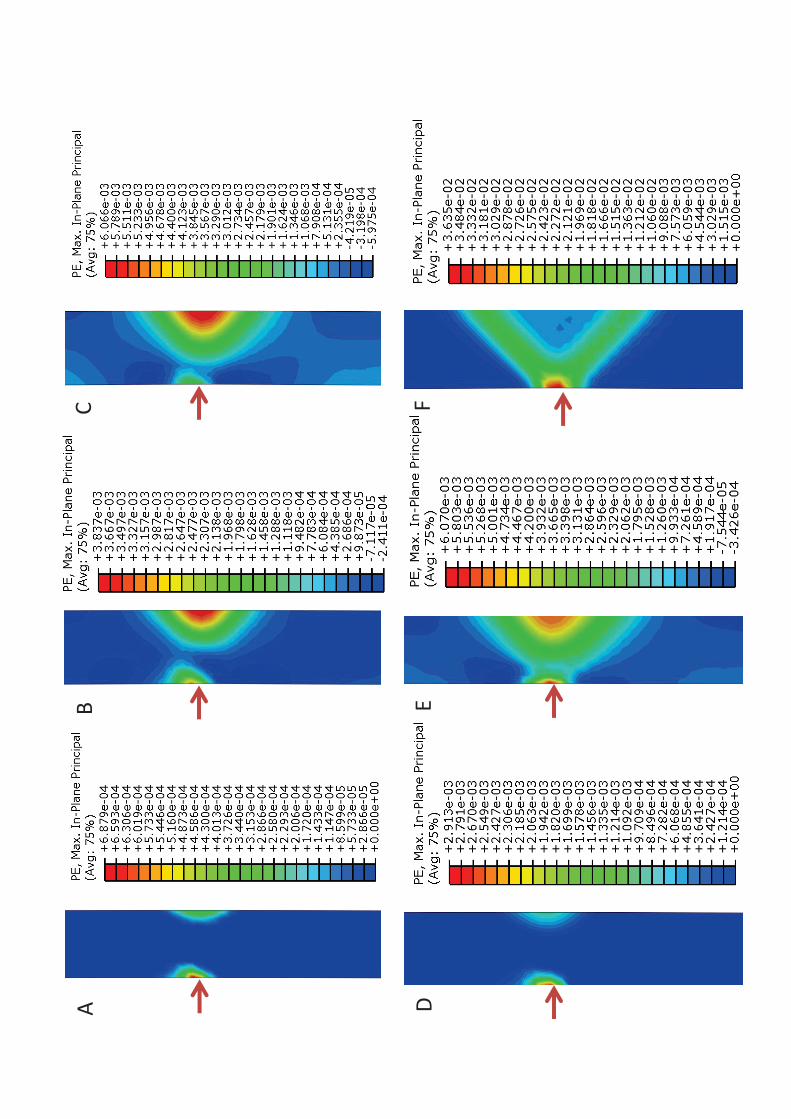
Fig. 13 shows a asymmetry in the equivalent plastic strain contour in the case of the unbonded
model. This asymmetry in the location of the plastic region may originate from slipping of
contact surfaces at the pellet cladding triple point before the complete axial expansion of the
fuel within the cladding occurs. In the bonded case this asymmetry is greatly reduced as once
contact is made the motion of the cladding inner surface will match the motion of the pellet.
While for the locking region the bonding between the fuel and the cladding may not be very
significant at the triple point, bonding and a power ramp forms a significant plastic region
through the cladding. This through cladding yielding would reduce the ductility at any pellet-
cladding interfaces. Considering radial cracks this would produce networks of plastic regions,
which combined with irradiation damage (in cladding He production) and loss of ductility
through creep are potential areas of failure.
3.4.3 Alumina spacer pellet influence
The alumina spacer pellet is shown as the half height pellet just above the pin end cap in Fig. 1.
The constant heat up and cooling of the fuel may cause wear on the welded end caps, alumina
has previously served as tube liners in abrasive environments and metallic component
protection in other ceramic fuels [37]. This protection was achieved due to the high thermal
conductivity and small thermal expansion of alumina. The spacer pellet is non-heat generating
and therefore serves as thermal protection to the fuel pin ends. In all load cases the spacer
pellet was able to protect the cladding and the weld points remained at coolant temperature.
This is up to 50°C lower than the cladding temperature at the midsection of the fuel pin. As well
as the reduced temperature in the cladding the stiffness of the spacer pellet, coupled with the
fact the fuel pellet adjacent to it is an ASG pellet, has led to reduced stresses in the end cap
region. This results in an equivalent plastic strain of 2.5 x 10⁻⁴ even after a power spike to 150%
power. The combination of reduced stress and temperature in the cladding has also reduced
the creep strain surrounding the spacer pellet reducing the risk of damage to the end cap welds
from creep ductility exhaustion.
The spacer pellet also limits the region of plastic deformation at the end caps to several surface
elements. This suggests yielding here is a consequence of spacer pellet friction with the
cladding. The plastic strain is more than an order of magnitude less than all other plastic regions

11
in the fuel pin. Without the spacer pellet the weld is expected to experience significant creep
and plastic deformation leading to very rapid degradation of the fuel pins ability to contain
fission products. The von Mises stress, creep and plastic strain can be seen in Fig. 14. The most
significant region of creep and plastic strain in the end caps results from the friction between
cladding and pellet and the geometry of the spacer, which places the region of significant plastic
strain (0.1%) at the intersection of the spacer pellets and the cladding (point a in Fig. 14).
3.5 Information management
The very large quantity of information that is produced from a single run of a whole pin, over a
whole life model, leads to a situation where it may be difficult to discern behaviour of the fuel as
a function of load history. There exists a very powerful indicator as to the condition of the fuel
(thermally and mechanically) in the value of the thermal conductivity plotted as a function of
time/burn-up (See, Fig. 15a). The thermal conductivity links almost all aspects of fuel
behaviour. It controls the fuel thermal profile, influencing its expansion and swelling, leading to
mechanical working of the cladding. The thermal conductivity has strong non-linear
temperature dependence (see, Fig. 15b). As the fuel expands and the fuel cladding gap closes,
the thermal profile responds to the change in the heat transfer coefficient of the gap, the change
in thermal profile would need to equilibrate with the thermal conductivity to reach steady state.
The thermal conductivity also responds to chemical changes, this can be from material change
as a consequence of reactor dwell or changes in the fuel’s heat generating state (local rating
differences). It would decrease as the fuel burns up and responds due to rating changes,
increasing or decreasing as fissile material is destroyed or created respectively.
Fig. 15a shows that the behaviour of the fuel can be described from analysis of a single material
property change. Following through life we find: Point A shows the initial fuel heat up. Here, the
centreline temperature increases with respect to the fuel surface temperature and therefore the
thermal conductivity reduces in the pellet centre by about 10%. Point B shows the period when
the cladding creeps down and the gap size is similar to the mean free path length of the filling
gas. At this time the fuel surface temperature increases and the thermal conductivity responds
by decreasing. Point C is when clad creep down is complete and the start of the fuel power spike
and cycling begins. Point D is long term operation where the increase in burn-up adversely
affects the fuel centre and surface thermal conductivity. Point E is the finish of the stabilisation
of the plutonium generation and diffusion and with full cladding contact the surface
temperature can stabilise. The steady decline of both the surface and the centreline thermal
conductivity correspond to the continual burn-up of the fuel while the fuel is in reactor. Fig. 14b.
shows the proposed thermal conductivity from reference [34]. Table 1 shows the different
contribution to the thermal conductivity. The properties are collected in such a way that each
contributing factor may be independently modelled, perhaps even on different length scales.
4.0 Conclusions
The implementation of a nuclear fuel performance code into a commercial FE package is
becoming more common place as the capabilities and performance of general FE packages
continue to improve. The benefits in a fuel performance code are:
· The usability of a FE based fuel performance code would be an enhancement over past
codes.

12
· Pre- and post-processors have lowered the entry barrier for the development of a fuel
performance model to permit the ability to model complicated systems.
· Typical runtimes for a 5 year axisymmetric model takes less than one hour on a single
core workstation.
The current model has implemented:
· Non-linear fuel thermal behaviour, including a complex description of heat flow in the
fuel. Coupled with a variety of different FE and finite difference models.
· Non-linear mechanical behaviour of the fuel and cladding including, fuel creep and
swelling and cladding creep and plasticity each with dependencies on a variety of
different properties.
· A fission gas release model which takes inputs from first principles calculations.
· Explicitly integrated inventory calculations performed in a coupled manner.
· Freedom to model steady state and transient behaviour using implicit time integration.
· The whole pin geometry is considered over an entire typical fuel life.
The model showed by examination of normal operation and a subsequent transient chosen for
software demonstration purposes:
· ABAQUS may be a sufficiently flexible platform to develop a complete and verified fuel
performance code.
· The importance and effectiveness of the geometry of the fuel spacer pellets was
characterised.
· The fuels performance under normal conditions (high friction no power spikes) would
not suggest serious degradation of the cladding in fuel life.
· Large plastic strains were found when pellet bonding was strong, these would appear at
all pellets cladding triple points and all pellet radial crack and cladding interfaces thus
showing a possible axial direction to cracks forming from ductility exhaustion.
Acknowledgements
One of the authors (R Mella) wishes to thank EPSRC for funding through a departmental
training account. Both authors wish to thank the Fuels Group at EDF energy, Barnwood,
Gloucester, for both financial support and discussions. However, the views expressed here
represent those of the authors and not necessarily those of EDF Energy.
References
[1] F. Bentejac, N. Hourdequin, in:, Pellet-clad Interaction in Water Reactor Fuels, Aix-
en-Provence, France, 2004, pp. 495–506.

13
[2] B. Michel, J. Sercombe, G. Thouvenin, Nucl. Eng. Des. 238 (2008) 1612.
[3] B. Michel, J. Sercombe, G. Thouvenin, R. Chatelet, Eng. Fract. Mech. 75 (2008) 3581.
[4] C. Struzik, D. Plancq, B. Michel, P. Garcia, C. Nonon, in:, Pellet-clad Interaction in
Water Reactor Fuels, Aix-en-Provence, France, 2004, pp. 507–517.
[5] M. Valach, J. Zymak, in:, Pellet-clad Interaction in Water Reactor Fuels, Aix-en-
Provence, France, 2004, pp. 441–451.
[6] S.P. Walker, R.T. Fenner, Nucl. Eng. Des. 138 (1992) 403.
[7] A. Yu, S.P. Walker, R.T. Fenner, Nucl. Eng. Des. 121 (1990) 53.
[8] G. Zhou, J.E. Lindbäck, H.C. Schutte, L.O. Jernkvist, A.R. Massih, in:, Pellet-clad
Interaction in Water Reactor Fuels, Aix-en-Provence, France, 2004, pp. 519–530.
[9] J.-S. Cheon, Y.-H. Koo, B.-H. Lee, J.-Y. Oh, D.-S. Sohn, in:, Pellet-clad Interaction in
Water Reactor Fuels, OECD, Aix-en-Provence, France, 2004, pp. 191–201.
[10] V. Guicheret-Retel, F. Trivaudey, M.L. Boubakar, R. Masson, P. Thevenin, in:, Pellet-
clad Interaction in Water Reactor Fuels, Aix-en-Provence, France, 2004, pp. 453–463.
[11] N. Marchal, C. Campos, C. Garnier, Comp. Mater. Sci. 45 (2009) 821.
[12] R.L. Williamson, J. Nucl. Mater. 415 (2011) 74.
[13] R.L. Williamson, J.D. Hales, S.R. Novascone, M.R. Tonks, D.R. Gaston, C.J.
Permann, D. Andrs, R.C. Martineau, J. Nucl. Mater. 423 (2012) 149.
[14] H.S. Aybar, P. Ortego, Prog. Nucl. Energ. 46 (2005) 127.
[15] G.A. Berna, C.E. Beyer, K.L. Davis, D.D. Lanning, FRAPCON-3: A Computer Code
for the Calculation of Steady-State, Thermal-Mechanical Behavior of Oxide Fuel Rods
for High Burn-up, Idaho National Engineering and Environmental Laboratory ,
NUREG/CR-6534, n.d.
[16] K.J. Geelhood, W.G. Luscher, C.E. Beyer, J.M. Cuta, FRAPTRAN 1.4: A Computer
Code for the Transient Analysis of Oxide Fuel Rods, NUREG/CR-7023, 2011.
[17] K. Lassmann, J. Nucl. Mater. 188 (1992) 295.
[18] EDF Energy, The ENIGMA Fuel Performance Code Description: Version 5.14, n.d.
[19] J.C. Killeen, J.A. Turnbull, E. Sartori, in:, International LWR Fuel Performance
Meeting, 2007, p. 1102.
[20] EDF Energy, Private Communications (2011).
[21] ABAQUS Software, Rising Sun Mills,166 Valley Street, Providence, RI. (2011).

14
[22] D.L. Olander, Fundamental Aspects of Nuclear Reactor Fuel Elements, 1978.
[23] K. Lassmann, F. Hohlefeld, Nucl. Eng. Des. 103 (1987) 215.
[24] A.M. Ross, R.L. Stoute, Heat Transfer Coefficient Between UO2 and Zircaloy-2,
Canadian Report AECL-1552, 1962.
[25] A.L. Lindsay, L.A. Bromley, Ind. and Eng. Chem. 42 (1950) 1508.
[26] P. Van Uffelen, R.J.M. Konings, C. Vitanza, J. Tulenko, Handbook of Nuclear
Engineering: Nuclear Engineering Fundamentals, 2010.
[27] I. Palmer, K. Hesketh, P. Jackson, Water Reactor Fuel Element Performance Computer
Modelling., 1983.
[28] K. Lassmann, H. Blank, Nucl. Eng. Des. 106 (1988) 291.
[29] G.P. Mezzi, F. Caligara, H. Blank, Nucl. Eng. Des. 73 (1982) 83.
[30] T. Helfer, P. Garcia, J.-M. Ricaud, D. Plancq, C. Struzik, in:, Pellet-clad Interaction in
Water Reactor Fuels, Aix-en-Provence, France, 2004, pp. 367–377.
[31] R.L. Williamson, D.A. Knoll, in:, 20th International Conference on Structural
Mechanics in Reactor Technology (SMIRT 20), Espoo (Helsinki), Finland, 2009, p.
1775.
[32] V.Z. Jankus, R.. Weeks, Nucl. Eng. Des. 18 (1972) 83.
[33] J.A. Turnbull, C.E. Bayer, Background and Derivation of ANS-5.4 Standard Fission
Product Release Model, NUREG/CR-7003, 2010.
[34] P.G. Lucuta, H. Matzke, I.J. Hastings, J. Nucl. Mater. 232 (1996) 166.
[35] P. Van Uffelen, G. Pastore, V. Di Marcello, L. Luzzi, Nuc Eng. and Tech. 43 (2011)
477.
[36] C.M. Allison, SCDAP/RELAP5/MOD3.1 Code Manual. Volume IV: MATPRO,
Idaho National Engineering Laboratory Technical Report, NUREG/CR-6150, 1993.
[37] J. Rouault, P. Chellapandi, B. Raj, P. Dufour, Handbook of Nuclear Engineering:
Nuclear Engineering Fundamentals, 2010.
Figure captions
Fig. 1: (a) Quarter section of a pin end showing half height spacer pellet (bottom) and cladding
locking into an ASG pellet (second bottom). (b) An ASG pellet, (c) a conventional annular fuel
pellet. Image depicts the end of the fuel pin showing the end stand and the welded in end caps.
15
Fig. 2: Meshes of axisymmetric pellet segments; A) Spacer pellet mesh and the end cap; b)
central region of an ASG pellet and surrounding cladding; (c) Interface between two pellets.
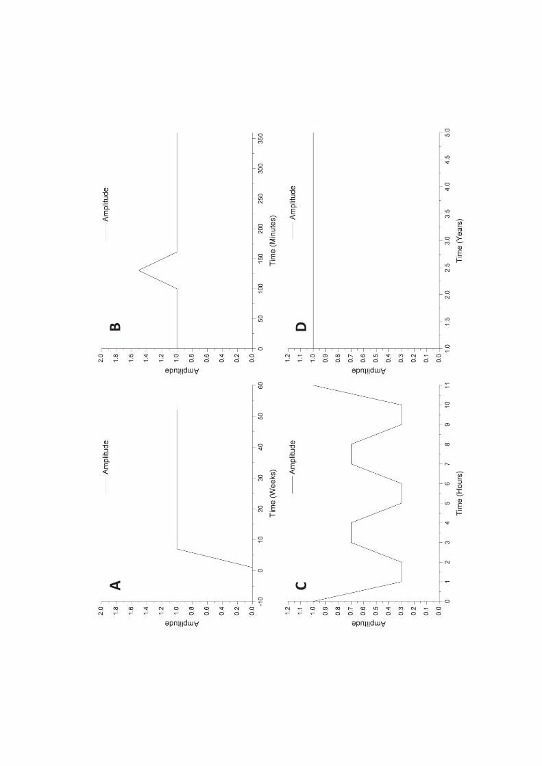
Fig. 3: Typical amplitude curve for heat up, long term steady operation and end of life ramping
and cycling. This figure shows the three domains of particular interest. (A) One week heat up to
100%. (B) Power profile of power spike at one year dwell time. (C) A short online refuelling
cycle. (C) Flat profile for the rest of life.
Fig. 4: Procedure executed within USDFLD subroutine, within ABAQUS to approximate the
increase in pressure within the fuel central hole.
Fig. 5: Computed pin elongation, from the centre of pin, for heat-up from zero power to different
values of volumetric power.
Fig. 6: Plot of the impact of fuel burn-up on the fuel centreline temperature. The figure shows
the fuels thermal profile at start of life and thermal profile at end of five year operation at 100%
power. While there is a change in thermal profile from the pellet cladding gap closing the
greatest difference in centreline temperature is from fuel material non-linearity.
Fig. 7: Axial thermal centreline profile of a segment of AGR fuel. Each segment is 5 pellets
enclosed at each end with an ASG pellet.
Fig. 8: shows the cladding radial displacements throughout the simulated fuel pellet life. The
plot of displacement is for a section of cladding over several standard fuel pellets. The
displacement plot shows that the creep down of the cladding on to the fuel occurs at about
6GWd/tU. The plot shows the bamboo pin shape expected with pelleted fuel.
Fig. 9: The volumetric power of a fuel pellet near the centre of the pin at different pellet radii,
the radii that correspond to A, B, C, D and E correspond to 1, 0.875, 0.75, 0.5, 0 from the surface
in units of pellet radius.
Fig. 10: Shown is the internal pin pressure, volume change due to fission gas and the average
fission gas release fraction for the AGR as a function of fuel burn-up. The fraction axis have
normalised units. The normalised units are defined as V-Vf/Vi-Vf for volume where the i and the
f subscripts stand for initial and final respectively. Similarly for pressure, P-Pf/Pi-Pf , where the i
and the f subscripts stand for initial and final respectively.
Fig. 11: Point of greatest displacement due to end cap doming as a result of fission gas release
and fuel expansion as a function of burn-up. Negative displacement defined as inward end cap
doming.
Fig. 12: (A) The von Mises stress (Pa) on a typical locking region after a heat-up to full power of
125 MW/m3, circled regions are points of highest stress. (B) Equivalent plastic deformation
after a typical heat-up to full power, still holding much of its symmetry. (C) Equivalent plastic
deformation at end of life after power spike to 150% full power of 187.5 MW/m3.
Fig. 13: (A), (B) and (C) show the plastic region at the triple point between cladding and two
separate pellets for the unbonded case, they show the plastic region at three different points,
after heat-up, while power spike is in progress and at the end of the power spike respectively.

16
(D), (E) and (F) show the plastic region at the same triple point between cladding and two
separate pellets for the bonded case for the same cases as (A), (B) and (C).
Fig. 14: (A), (B) and (C) show the protective effect of the spacer pellet on the pin end caps, they
show the von Mises stress (Pa), equivalent creep strain and the equivalent plastic strain at the
end of life. The figure only shows a cross section of cladding end with the axisymmetric model
rotated by 180°. The fuel and spacer pellets have been removed to show clearly the cladding
stress state.
Fig. 15a: The thermal conductivity of a standard pellet near the centre of the pin throughout
life. Shown is the fuel centreline and fuel surface thermal conductivity. 15b: The thermal
conductivity profile as a function of temperature and burn-up proposed by Lucuta et al. [33].

Table 1: Model run parameters.
Property Value
Volumetric Body Flux (MW m-3) 125
Fast Neutron Flux (n m-2 s-1) 174 10´
Coolant Pressure (MPa) 4
Coolant Outlet Temperature (°C) 650
Pin Filling Gas Helium
Fill Gas Initial Pressure (MPa) 0.1
Fuel Surface Roughness (10-6 m) 3
Clad Surface Roughness (10-6 m) 2
Fuel Emissivity 0.88
Clad Emissivity 0.8
Clad Hardness (GPa) 1
Pellet-Clad Coefficient of Friction 0.8
Number of Pellet Cracks 5
Table 2: Fuel material properties and their associated parameters.
Property Symbol Units Form Parameters Source
Thermal
Conductivity
λ W m-1
K-1 1 2 3 4 0( ) ( ) ( ) ( ) ( )k k p k x k r Tb l
See Source [33]
Specific Heat
Capacity
J Kg-1
K-1 ( 293)a bk k T+ -
[18]
Density ρ Kg m-3 10690 [18]
Thermal
Expansivity
α K-1 2 3
a b cEx T Ex T Ex T+ +
[18]
Young’s
Modulus
E MPa 1.94E5
[18]
Poisson’s
Ratio
ν - 0.325 [18]
Total Creep
Rate
s-1 [18]
Low Stress
Creep Rate
s-1
1.226E-7/G
45220.0 K
[18]
High Stress
Creep Rate
s-1
8.8E3
[18]
Irradiation
Creep Rate
s-1 1.4E-30
[18]
Fast Neutron
Flux Rate N m-2
s-1
4E15 (at 100% power)
Solid Fission
Product
Swelling
increment
swseD - 56.407 10sws Bue rD = ´ D [36]
Table
Gaseous
Fission
Product
Swelling
increment
swgeD - 31
11.73 0.0162(2800 )
0.021
2.25 10
(2800 )
swg
T
Bu
Bu T e
e r
e r-
- -
-
D = ´
D -
[36]
All temperatures (T) are absolute temperature.Bu and BuD is the burn-up and burn-up
increment respectively with units of %FIMA. Input G is the grain size in mils. is the total
fractional porosity as input from user.
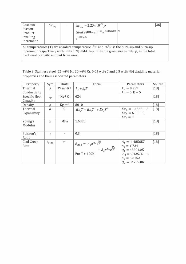
Table 3: Stainless steel (25 wt% Ni, 20 wt% Cr, 0.05 wt% C and 0.5 wt% Nb) cladding material
properties and their associated parameters.
Property Sym Units Form Parameters Source
Thermal
Conductivity
λ W m-1 K-1 a bk k T+
[18]
Specific Heat
Capacity
J Kg-1 K-1 624
[18]
Density ρ Kg m-3 8010
[18]
Thermal
Expansivity
α K-1 2 3
a b cEx T Ex T Ex T+ +
[18]
Young’s
Modulus
E MPa 1.68E5
[18]
Poisson’s
Ratio
ν - 0.3 [18]
Clad Creep
Rate
s-1
For T > 400K
43801.0K
34789.0K
[18]

Fig
ure

A
B
C
Inn
er
Pe
lle
t R
ad
ius
Ou
ter
Pe
lle
t R
ad
ius
Ce
ntr
eli
ne
A
B
C
D


Ce
ntr
al
Ho
le
UO
2
Ga
p
Co
ola
nt

A
B


A
B
C
Hig
he
st p
ress
ure
A
B
C
D
E
F

A
B
C
Pin
axi
al
dir
ect
ion
a

1.5
2
2.5
3
3.5
4
4.5
5
5.5
40
0
14
00
2
40
0
1%
2
%
3%
4
%
5%
6
%
Tem
pe
ratu
re (
K)
Thermal Conductivity W/mK
1.9
2.1
2.3
2.5
2.7
2.9
3.1
3.3
0
5
10
1
5
Fu
el C
en
tre
Fu
el S
urf
ace
Thermal Conductivity W/mK
Bu
rnu
p (
GW
d/t
U)
A
B
C
D
E
(a)
(b)
Bu
rnu
p %
at.
U (
FIM
A)