Embed Size (px)
Citation preview

NTY3-150

NTY3-1501
NTY3-150
One hit machiningFinished parts, complete in one setup
M×3Three Milling Motor
Y×3Three Y-axes
High Productivity Multitasking MachineFrom diversified small-lot production to mass production
3 Turrets 3 Y-axes
2NTY3-150
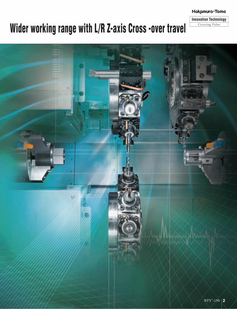
Wider working range with L/R Z-axis Cross -over travelInnovation Technology
Creat ing Va lue

3 NTY3-150
L/R Z-axis Cross-over travel
No work in process
Less setup time
Complete in one setupTo p L e a d e r o f O n e - h i t M a c h i n i n g
High Productivity
115mm 115mm
New New

4NTY3-150
Y×3M×3Milling-tool motor
5.5/3.7kW × 3
Y-axis travel Upper : ±45mmLower : ±35mm
Simultaneous Milling with upper / lower tool on left spindle. Simultaneous Milling with upper / lower tool on right spindle.
72Up to 72 tool stations
for Turning, 48 tool stations for milling tools.
12 / 24 - Station Turret
24 + 24 + 24
Y-axis on upper and lower turrets
Double Performance!

5 NTY3-150
NTY3-150NTY3-150 High-Performance State-of-the art Multitasking machineNow with Z-axis cross-over travel

6NTY3-150
NTY3-150
T×3Three turretM×3Three Milling Motor
Y×3Three Y-axes
S×2Twin-SpindleC×2C-axes
High-Performance State-of-the art Multitasking machine
B2B-axis
■Capacity φ51mm φ65mm
Max. turning diameter 225mm
Max. turning length 685mm
Distance between spindles max. 970mm / min. 200mm
Bar capacity φ51mm φ65mm
Chuck size 165mm (6")
■Axis travel
Slide travel (X1 / X2 / X3) 160.5 / 160.5 / 160.5mm
Slide travel (Z1 / Z2 / Z3) 235 / 235 / 685mm
Slide travel (Y1 / Y2 / Y3) ±45 / ±45 / ±35mm
Slide travel (B) 770mm
■Spindle L, R
Spindle speed 5,000min-1 4,500min-1
Spindle motor output (L / R) 15/11kW / 11/7.5kW
■Turrets
Number of turrets (Upper / Lower) 2 / 1
Driven-tool spindle speed 6,000min-1
Drive motor 5.5/3.7kW 24/16N·m
Type of turret head / Number of indexing pos. Dodecagonal drum turret / 24
Drive type / Number of driven-tool stations Individual rotation / 12
■General
Floor space (L×W×H) 3,814mm × 2,218mm × 2,200mm
Machine Weight (incl.control) 10,000kg

Standard
7 NTY3-150
NTY3-150NTY3-150
72stations
Left Spindle
Lower Turret ×1
12 / 24 station turret◆ Number of driven-tool stations : 12◆ Servo-driven turret
5.5/3.7kW24/16N.m6,000min-1
Milling motor
Y-axis travel ±35mm
Spindle motor
15 / 11kW5,000min-1
Spindle motor
15 / 11kW4,500min-1
Bar capacity φ51mm Bar capacity φ65mm
C-axisC-axis synchronisation
C-axisC-axis synchronisation
Standard Option
Machine Structure
High-rigidity turrets
Upper Turrets × 2
Lower Turret × 1

Standard
8NTY3-150
Right Spindle
Upper Turrets ×2
12 / 24 station turret◆ Number of driven-tool stations : 12◆ Servo-driven turret
5.5/3.7kW24/16N.m6,000min-1
Milling motor
Y-axis travel ±45mm
Larger window ensures better visibility
Spindle motor
11 / 7.5kW5,000min-1
Spindle motor
15 / 11kW5,000min-1
Bar capacity φ51mm Bar capacity φ51mm
C-axisC-axis synchronisation
C-axisC-axis synchronisation
Standard Option
Method Swing / Gripper
Workpiecesize
Diameter [mm] φ12 - 65
Length [mm] 15 - 150
Weight [kg] 3.0
Ejecting method Belt conveyor & Chute
Parts catcher G Option
E n s u r e s S t a b l e A c c u r a c y

9 NTY3-150
15 / 11kW
Left Spindle Motors
11 / 7.5kW
Right Spindle Motors
NTY3-150NTY3-150
1000
100
10
10
100
1
0.110 100 10000
Torque(N・m)
Output(kW)
Spindle speed(min-1)
30 4500912
1095
1000
157.1N・m (S3 25%)157.1N・m (S3 25%)131.1N・m (S2 30min. S3 60%)131.1N・m (S2 30min. S3 60%)
95.9N・m (S1 CONT.)95.9N・m (S1 CONT.)
15kW15kW
11kW11kW
Rotating speed : 4,500min-1 φ65mm
1000
100
10
10
100
1
0.110 100 1000 10000
Torque(N・m)
Output(kW)
Spindle speed(min-1)
50 50001050
1260
136.4N・m (S3 25%)136.4N・m (S3 25%)113.7N・m (S2 30min. S3 60%)113.7N・m (S2 30min. S3 60%)
83.4N・m (S1 CONT.)83.4N・m (S1 CONT.)
15kW15kW
11kW11kW
Rotating speed : 5,000min-1 φ51mm
1000
100
10
10
100
1
0.110 100 1000 10000
Torque(N・m)
Output(kW)
Spindle speed(min-1)
50 50001176
1260
89.3N・m (S3 25%)89.3N・m (S3 25%)83.4N・m (S2 30min. S3 60%)83.4N・m (S2 30min. S3 60%)
56.8N・m (S1 CONT.)56.8N・m (S1 CONT.)
11kW11kW
7.5kW7.5kW
Rotating speed : 5,000min-1 φ51mmStandard Standard
NTY3-150S×2Twin-Spindles
Option
High-Performance Turning and Milling Motors.
Simultaneous machining with synchronized left and right spindles contribute to faster cycle times.

10NTY3-150
5.5 / 3.7kW
Upper & Lower Milling Motors
1000
100
10
10
100
1
0.110 100 1000 10000
Torque(N・m)
Output(kW)
Rotating speed(min-1)
60 60002230
24.0N・m (S2 30min. S3 60%)24.0N・m (S2 30min. S3 60%)
16N・m (S1 CONT.)16N・m (S1 CONT.)
5.5kW5.5kW
3.7kW3.7kW
Rotating speed : 6,000min-1Standard
NTY3-150Y×3Three Y-axes
M×3Three Milling Motors
High-Performance Turning and Milling Motors. From simple to complex partsOne hit machining from raw material to finished part
In addition to milling or drilling simultaneously with upper and lower turrets, improved chip-removal capabilities contribute to drastically faster cycle times.

11 NTY3-150
Advanced Production System
Nakamura-Tome Intelligent System
Industry 4.0
IoT
Big Data
Program storage length Total 512Kbyte(1,280m)
Total 1Mbyte(2,560m)
Total 2Mbyte(5,120m)
Total 4Mbyte(10,240m)
Total 8Mbyte(20,480m)
Program registered number Total 1,000 Total 1,000 or Total 2,000 Total 1,000 or Total 4,000
Tool offset pairs 99 + 99 + 99 (op. Total 999)
Standard / Option
• 19 inch color LCD Touch panel • PC memory 8GB • QWERTY Key board • Windows 8 • Touch Pad • USB 2.0 port × 2
Cut-in Check
Main featuresThe machine can be stopped immediately while in automatic cycle. After reading G00 command in the machining program, the Spindle, Tool spindle, Axis Feeding and Coolant will stop. It is faster than M01 optional stop. After checking the machine internal status, the machining can be restarted by pressing "Program restart" button.
• NT Manual Guide i• NT Work Navigator• Airbag (Overload detection)• Advanced NT Nurse• Status Display Function• Setup Display• Trouble Guidance• Productivity Function
• Operation Level Control Function• Warm up Function• Built-in Loading Device Setting Screen (op.)• Parts Catcher G Operation Function (op.)• NT Machine Simulation• NT Collision Guard• NT Multitasking Office (op.)• Net Monitor (op.)• 3D Smart PRO
Cut-in Check

12NTY3-150
Soft work pusher Soft quill pusher cycleG131 G376
This cycle is used during part transfer from left to right side spindle. Once part contact with the jaws or stopper of the right side spindle has been confirmed, the right side spindle servo axis stops.
• Contact force can be changed in the program.• It is possible to set OK/ NG range as well.• An additional work pusher for the right side is not required and cycle time
can be reduced.
Thrust force of center support can be set in the program by using servo motor technology, which help keep a constant pushing thrust during cutting.
• It is available for Z axis and B2 axis.• Quill thrust force can be changed in the program.• It is possible to set OK/ NG range as well.
Waiting tool number for left upper turret
Waiting tool number for right upper turret
Driven-tool Rotating Speed
Work counter
Spindle Status
Cycle start condition is popping up by pressing reference position LED.
Color of perimeter becomes white when override setting is 100%.
Selected head shown in blue color
Remaining count
Value
Turret status display Machine status display Load status display
Spindle RPM
• Blue : Index ready• Green : Reference position return • Green Flashing : 2nd Reference position return• Blue : Cycle start ready
Reference position LED
Tool number is displayed during automatic cycle.
Coolant status
Automatic mode
Manual mode
Manual mode
Blank
Middle pf process
Part complete
Remnant
Quill
• Green : Automatic operation• White : Feed hold • Yellow : Warning• Red flashing : Alarm
Operating status display
Counter and Remaining counter information are displayed. Ticker can be stopped by touching the screen.
Auxiliary information display
Most used Icons can be registered at right side of display.
Shortcut bar
Spindle load meter
• Red : 120% -• Yellow : 100% -120%• Green : 0 -100%
Load meter
• Red : 120% -• Yellow : 100% -120%• Green : 0 -100%
Waiting tool number for lower turret

13 NTY3-150
+ AirbagNT Machine Simulation / NT Collision Guard
Dual safetyDual safety
Simulation is performed to
check the programs without
running the machine.
This helps prevent machine
collisions due to programming
or setup errors.
Simulation of part machining.
There are several view screen display
settings, such as machine display,
turret display and tooling display.
It is possible to choose between
"with" or "without" program
display. The color of the program
block being simulated can be set
to be displayed in a different color.
"Distance to go" and "Modal information" can be checked during with simulation.
Process
Rapid feed and Cutting feed can be adjusted using override setting. It is possible to make Simulation of each process, or to use single block.
Single block
• Model setup was simplified.Type of tool being indexed is automatically sorted out from the program, and the tool model can be selected from a displayed list.
Preventive safety technology - Machine collisions are avoidable!
Prevent the collision due to tooling, chuck, and program.
This function is available in automatic mode
and manual mode. Collisions can be prevented,
especially after modifying the program, or
changing the tool geometry offset. Registered
machine data, chucks, tools, holders, and
parts are used to monitor the machine during
automatic, manual or jog movement, and
recognize in advance collisions before they
happen. Even turret indexing is monitored to
avoid collisions, drastically reducing machine
collision risks, especially during set up.
NT Machine Simulation
Double safety features for maximum protectionNT collision Guard to avoid machine collision and Air bag function (Abnormal load detection) to
minimize damage even in case of collision.
NT Collision Guard

14NTY3-150
NT Work Navigator
Even with barrier function, machine collisions may occurSoft barrier function is not perfect. If wrong data is input, a collision will occur.
When unavoidable human error results in machine collision, there is no reason to panic.All Nakamura-Tome machines are equipped with a safety feature called “airbag” (overload detection), which will greatly reduce the impact force and prevent heavy damage to the machine.
Without AirbagMachine will not be
stop immediately.
The slide continues to
move even after collision.
With Airbag
Retraction within 0.008 secCrash !
Within 8 milliseconds after the crash,
servo motor-feeding direction is
reversed and the machine stops
in EMG mode.
Crash
* This feature does not mean zero impact.▲ VideoVideo
Nakamura-Tome machines will not break for the slightest collision, as other machines do. The function minimize damage in case of collision.
• Advanced NT Work Navigator !Navigation function is expanded to also include the X and Y-axis. Coordinate Recognition can made the part’s outer surface in the X or Y-Axis direction.
• No fixtures requiredMachining parts with non-round shapes, such as forgings or castings requires that the raw part coordinates be recognized by the CNC control. In order to achieve this without requiring extra cost or additional options, the NT Navigator is used. It works just by touching the part with a simple inexpensive probe (mostly round bar mounted on a tool holder) and using the torque control feature of the servo-motor, which is to record required coordinates in the CNC. The NT Navigator is a cost cutting feature in multitasking machines, eliminating the need for positioning fixtures and special clamping devices.
New Navigator for X-axis and Y-axis
Y Z B CX
Airbag (Overload detection) NT Work Navigator
▲
Other companies’ machine
Input material dimension
Input drill length
Input jaw shape
Input tool overhang
Input rotating center shape
That…
This…
Inputting a great amount of data comes
with the risk of making mistakes

Machine Dimensions
15 NTY3-150
NTY3-100
Dimensions : when control panel is stored away for transport.3814
Spindle center
Spindle center
620
695.1
852.8
1372.5 32.7
1050
Door ST885
Door opening865 20
218.5 495
1040 970 1090
34 1000 1050 680
2258
2147.7
742.5 1372.5 32.7
1270
2010
2200
2137.7
MAX. 2247
Left spindle nose Right spindle nose
NTY3 3T 3Y
S E R I E SBar Capacityφ42 φ80
6” 8”Chuck Size.
Unit : mm

Slide Travel Range
16NTY3-150
NTY3-150 NTY3-250
370 230 370
Z1=-235Z2=-235
95
135
95
135
Z1=+115
Z2=+115
350 350
2.52.5 2.5
2.5
2.52.5
2.5 2.5
2.5
2.5
S.LS
S.LS
S.LS
S.LS
S.LS
S.LS
80 80150
X1=-160.5
X2=-160.5
54.5
170
54.5170
B2=770
2.5
2.5
2.5
2.5
2.5
2.5
S.LS S.LS
Z3=-335 Z3=+350
485
385
385
X3=-160.5
170
54.5
150 135
110 95
685
Distance between spindles 970
2.5 2.5
2.5 2.5
2.5
2.5
2.5
2.5
2.5 2.5
Left spindleA2-5
Right spindleA2-5
S.LS S.LS
S.LS
S.LS
S.LS80
Y1/Y2=+45 Y1/Y2=-45
90
22
1.51.5 S.LSS.LS
Y3=-35 Y3=+35
70
1.52
1.52
S.LSS.LS
Bar Capacityφ42 φ80
6” 8”Chuck Size.
Unit : mm

Tooling System Diagram
17 NTY3-150
24ST
B1021252-01 / B1022252-01Turning Holder (AL) Forward*
*
*
*
*
*
*
*
*
*
*
*
*
*
*
R145103R145102
R145103R145102
Qualified Tool□25×100□25.4×100
Qualified Tool□20×125□19.05×125
Qualified Tool□25×130□25.4×130
Qualified Tool□20×125□19.05×125
Qualified Tool□20×95□19.05×95
N3170(φ25)N3180(φ25.4)Set Ring
N3171(φ32)N3181(φ31.75)Set Ring
Qualified Tool□20×102□19.05×10²
MetricInch
AC1310 / AR1390Cross Holder (Std.)(MAX.φ16)
6000min-1
AC1313 / AR1393Straight Holder (Std.)(MAX.φ16)
M2112(φ12)M2113(φ10)M2122(φ12.7)M2123(φ9.525)Tool Holder
M2110(φ20)M2111(φ16)M2120(φ19.05)M2121(φ15.875)Round Hole Bush
B1221252-01 / B1222252-01Turning Holder (AL) Reverse
B1031251-01 / B1032251-01Turning Holder (AS)
B1031201-01 / B1032201-01Turning Holder (AS)
B1011202-01 / B1012202-01Turning Holder (A) Forward
B1211202-01 / B1212202-01Turning Holder (A) Reverse
B1111202-01 / B1112202-01Cut-off Holder Forward
B1311202-01 / B1312202-01Cut-off Holder Reverse
B1021201-01 / B1022201-01Turning Holder (AL) Forward
B1221202-01 / B1222202-01Turning Holder (AL) Reverse
B1041251-01 / B1042251-01Turning Holder (B)
B1041201-01 / B1042201-01Turning Holder (B)
Turret Hoad(Upper / Lower)
B1411254-01 / B1412254-01Boring Holder(φ25)(φ25.4)
B1411254-12 / B1412254-12Boring Holder (Coolant through)(φ25)(φ25.4)
B1421251-01 / B1422251-01Double Boring Holder (A)(φ25)(φ25.4)
B1441252-01 / B1442252-01Triple Boring Holder(φ25)(φ25.4)
B1091252-01 / B1092252-01Turning Boring Holder (AL)(φ25)(φ25.4)
B1051201-01 / B1052201-01Double Turning Holder (AL)
B1411321-01 / B1412321-01Boring Holder(φ32)(φ31.75)
B1411321-12 / B1412321-12Boring Holder (Coolant through)(φ32)(φ31.75)
N1150(φ20) N1151(φ25)M2885(φ9.05) M2886(φ12.7)M2887(φ15.875)Round Hole Bush
HS130(φ6) HS131(φ8) HS132(φ10)HS133(φ12) HS134(φ16)M2682(φ12.7) M2688(φ9.525)Tool Holder For * Marked tools, coolant
comes out from the tool holders on both sides, when cutting on either left or right side spindle.As for other tool holders, additional coolant piping mounted on holders or turret face is necessary.

Machine Specifications Control Specifications
18NTY3-150
■itemsControl type FANUC 31i-B 3-PATH
■Controlled axesControlled axes 13axes
Least command incrementL Upper : 4axes (X1, Z1, C1, Y1)R Upper : 4axes (X2, Z2, C2, Y2)Lower : 4axes (X3, Z3, C3 [C1, C2], Y3, B2)
■Input commandLeast input increment 0.001mm / 0.0001inch (diameter for X-axis), 0.001°Least command increment X: 0.0005mm, Z : 0.001mm, C : 0.001°, B2 : 0.001mm, Y: 0.001mmMax.programmable dimension ±999999.999mm /±39370.0787inch, ±999999.999°Absolute / incremental programming X, Z, C, Y, B2 (absolute only for B2) / U, W, HDecimal input StandardInch / Metric conversion G20 / G21Programmable data input G10
■Feed function
Cutting feed
feed / min X : 1 - 8000mm/min, 0.01 - 314in/min (1 - 4800mm/min, 0.01 - 188in/min)Z : 1 - 8000mm/min, 0.01 - 314in/min (1 - 4800mm/min, 0.01 - 188in/min)C : 1 - 4800°/minY : 1 - 8000mm/min, 0.01 - 314in/min (1 - 4800mm/min, 0.01 - 188in/min)
B2 : 1 - 8000mm/min, 0.01 - 314in/min (1 - 4800mm/min, 0.01 - 188in/min)feed / rev : 0.0001 - 8000.0000mm/rev (0.0001 - 4800.0000mm/rev)
0.000001 - 50.000000in/revThe maximum cutting feed rate is the value in AI contour control mode.It is also on with G316 command. The values in parentheses are normal values.
Dwel G04Feed per minute / Feed per revolution G98 / G99Thread cutting G32F designationThread cutting retract StandardContinuous thread cutting StandardVariable lead threading G34Handle feed Manual pulse generator 0.001/ 0.01/ 0.1mm,°(per pulse)Automatic acceleration / decelaration StandardLinear accel. / decel. After cutting feed interpolation StandardRapidfeed override F0, 25, 50, 100% (changeable to every 10% by switch)Cutting feedrate override 0 - 150% (each 10%)AI contouring control I G5.1Spindle override 50% - 120% Set every 10%
■Program memoryPart program storage length 512kbyte (Total 1,280m)Part program editing delete, insert, changeProgram number search StandardSequence number search StandardAddress search StandardNumber of registerable programs 1,000 programsProgram storage memory Backed up by batteryMultiple program simultaneous editing Standard
DNC operation through memory cardStandard (Only one turret can access memory card at a time) (not including memory card)
Extended part program editing Standard (Replacement of word, address, cut & paste for word / character, cancel operation, copy or move the program)
■Operation and displayHMI (Human Machine Interface) NT Smart XOperation panel : Display 19” color SXGA LCD touch panelOperation panel : keyboard QWERTY keyboard
■Programming assist functioncircular interpolation R programming StandardDirect drawing dimension programming or Chamfering/Corner R Standard (Direct drawing dimension programming is standard)Canned cycle G90, G92, G94Multiple repetitive canned cycle G70 - G76Multiple repetitive canned cycle II G71, G72Canned cycle for drilling G80 - G89Axis recomposition Standard (used for L C-axis control · R C-axis control from the lower side)Sub program StandardBalance cut G68, G69Custom macro Standard (common variable#100 - #149, #500 - #549)Additional customer macro variables Standard (After addition, #100 - #199, #500 - #999)FS15 tape format StandardLuck-bei II NT Manual Guide i StandardAbnormal load detection function StandardNT Work Navigator Standard (not including contact bar)NT Nurse StandardNT Collision Guard Standard
■Mechanical supportRigid type StandardSpindle synchronised control StandardC axis synchronised control Standard (G496 C1, fast forward positioning)Spindle orientation Standard
■NT Smart XO/S Windows Embedded 8.1 Industry PROPointing device Touch padMemory 8GB
■Capacity φ51mm φ65mm (op.)Max. turning diameter 225mmStandard turning diameter 150mmDistance between spindles max. 970mm / min. 200mmMax. turning length 685mmBar capacity 51mm 65mmChuck size 165mm (6")
■Axis travelSlide travel (X1 / X2 / X3) 160.5mm / 160.5mm / 160.5mmSlide travel (Z1 / Z2 / Z3) 235mm / 235mm / 685mmSlide travel (Y1 / Y2 / Y3) ±45mm /±45mm /±35mmSlide travel (B) 770mmRapid feed X1 / X 2 / X3 20m/min-1
Rapid feed Z1 / Z2 / Z3 40m/min-1
Rapid feed B axis 40m/min-1
Rapid feed Y1 / Y2 / Y3 8m/min-1
■Left and right spindlesSpindle speed 5,000min-1 4,500min-1 Spindle speed range SteplessSpindle nose A2-5 A2-6Hole through spindle 65mm 80mmI.D. of front bearing 90mm 110mmHole through draw tube 52mm 66mm
■C-axisLeast input increment 0.001°Least command increment 0.001°Rapid index speed 600min-1
Cutting feed rate 1- 4800°/minC-axis clamp Disk clampC-axis connecting time 1.5 sec.
■Upper & Lower turretsType of turret head Dodecagonal drum turretNumber of driven-tool stations 12Number of index positions 24Tool size (square shank) □25mmTool size (round shank) φ32mm
■Rotating toolRotary system Individual rotationDriven-tool spindle speed 6,000min-1
Spindle speed range SteplessNumber of driven-tool station 12
Tool shankStraight holder φ1mm - φ16mmCross holder φ1mm - φ16mm
■Drive motorL-spindle 15/11kWR-spindle 11/7.5kW (op.15/11kW)Driven tools 5.5/3.7kW
■GeneralHeight 2,200mmFloor space (L × W) 3,814mm × 2,218mmMachine weight (incl. control) 10,000kg
■Power requirementspower supply 43.8kVAAir supply 400 - 450NL/min, 0.5 - 0.7MPa
● Safety devices such as various interlocks, fences for robotics, auto loading device, work stocker, automatic fire extinguisher etc. are available as options which can be included in your purchase package. Please contact our local distributor and dealer for your specific requirements.
● Precautions about the use of cutting coolant Synthetic Coolants are Damaging to Machine Components. Concerning the
use of cutting fluids, cautions have to be taken on the type of coolant being used. Among coolants available in the market, some types are damaging to machine components and should be avoided. Typical damages are turcite wear, peeling of paint, cracking and damage to plastics and polymers, expansion of rubber parts, corrosion and rust build up on aluminum and copper. To prevent such damages, coolants that are synthetic, or containing chlorine have to be avoided. Machine warranty terms do not apply to any claims or damage arising from the use of improper coolant.

Cat.No.0149E01011702N
NAKAMURA-TOME PRECISION INDUSTRY CO., LTD.http://www.nakamura-tome.co.jp
Netsuno 15, Hakusan city, Ishikawa, 920-2195 JapanPhone : +81 76 273 8100 Fax : +81 76 273 4312E-mail : [email protected]
• This catalog was published in February, 2017. Specifications, illustrations and data given herein are subject to change without notice.
• The products in this catalog are controlled based on Japan's "Foreign Exchange and Foreign Trade Law". The export of the products are subject to an export license by the Japanese government.