Embed Size (px)
Citation preview

Cat. No. V034-E1-5
Programmable TerminalNT30/30C

NT30/30C Programmable TerminalOperation ManualRevised January 2001

iv
!
!
!
v
Notice:OMRON products are manufactured for use according to proper procedures by a qualified operatorand only for the purposes described in this manual.
The following conventions are used to indicate and classify precautions in this manual. Always heedthe information provided with them. Failure to heed precautions can result in injury to people or dam-age to property.
DANGER Indicates an imminently hazardous situation which, if not avoided, will result in death orserious injury.
WARNING Indicates a potentially hazardous situation which, if not avoided, could result in death orserious injury.
Caution Indicates a potentially hazardous situation which, if not avoided, may result in minor ormoderate injury, or property damage.
OMRON Product ReferencesAll OMRON products are capitalized in this manual. The word “Unit” is also capitalized when it refersto an OMRON product, regardless of whether or not it appears in the proper name of the product.
The abbreviation “Ch,” which appears in some displays and on some OMRON products, often means“word” and is abbreviated “Wd” in documentation in this sense.
The abbreviation “PC” means Programmable Controller and is not used as an abbreviation for any-thing else.
The abbreviation “host” means a controller, such as an FA computer, that controls a PT (Program-mable Terminal).
Visual AidsThe following headings appear in the left column of the manual to help you locate different types ofinformation.
Note Indicates information of particular interest for efficient and convenient operationof the product.
Reference Indicates supplementary information on related topics that may be of interest tothe user.
1, 2, 3... 1. Indicates lists of one sort or another, such as procedures, checklists, etc.
OMRON, 1995All rights reserved. No part of this publication may be reproduced, stored in a retrieval system, or transmitted, in anyform, or by any means, mechanical, electronic, photocopying, recording, or otherwise, without the prior written permis-sion of OMRON.
No patent liability is assumed with respect to the use of the information contained herein. Moreover, because OMRON isconstantly striving to improve its high-quality products, the information contained in this manual is subject to changewithout notice. Every precaution has been taken in the preparation of this manual. Nevertheless, OMRON assumes noresponsibility for errors or omissions. Neither is any liability assumed for damages resulting from the use of the informa-tion contained in this publication.

vi

TABLE OF CONTENTS
vii
PRECAUTIONS xi. . . . . . . . . . . . . . . . . . . . . . . . . . . . . . . . .1 Intended Audience xii. . . . . . . . . . . . . . . . . . . . . . . . . . . . . . . . . . . . . . . . . . . . . . . . . . . . . . . . . . .2 General Precautions xii. . . . . . . . . . . . . . . . . . . . . . . . . . . . . . . . . . . . . . . . . . . . . . . . . . . . . . . . . .3 Safety Precautions xiii. . . . . . . . . . . . . . . . . . . . . . . . . . . . . . . . . . . . . . . . . . . . . . . . . . . . . . . . . . .
SECTION 1Functions of the NT30/30C 1. . . . . . . . . . . . . . . . . . . . . . . .1-1 Role and Operation of NT30/30C 2. . . . . . . . . . . . . . . . . . . . . . . . . . . . . . . . . . . . . . . . . . .1-2 Functions of NT30/30C 4. . . . . . . . . . . . . . . . . . . . . . . . . . . . . . . . . . . . . . . . . . . . . . . . . . .1-3 System Configuration 7. . . . . . . . . . . . . . . . . . . . . . . . . . . . . . . . . . . . . . . . . . . . . . . . . . . . .1-4 Communications Using the Direct Connection Function 8. . . . . . . . . . . . . . . . . . . . . . . . .1-5 Before Operating 13. . . . . . . . . . . . . . . . . . . . . . . . . . . . . . . . . . . . . . . . . . . . . . . . . . . . . . . .
SECTION 2Hardware Settings and Connections 15. . . . . . . . . . . . . . . .2-1 Description of Parts and Settings 16. . . . . . . . . . . . . . . . . . . . . . . . . . . . . . . . . . . . . . . . . . . .2-2 Installation 19. . . . . . . . . . . . . . . . . . . . . . . . . . . . . . . . . . . . . . . . . . . . . . . . . . . . . . . . . . . . .2-3 Connecting to the Support Tool 21. . . . . . . . . . . . . . . . . . . . . . . . . . . . . . . . . . . . . . . . . . . . .2-4 Installing the System Program 22. . . . . . . . . . . . . . . . . . . . . . . . . . . . . . . . . . . . . . . . . . . . . .2-5 Connection to a PC by Host Link via RS-232C 23. . . . . . . . . . . . . . . . . . . . . . . . . . . . . . . .2-6 Connection to a PC by Host Link via RS-422A 40. . . . . . . . . . . . . . . . . . . . . . . . . . . . . . . .2-7 Connection to a PC by the NT Link 56. . . . . . . . . . . . . . . . . . . . . . . . . . . . . . . . . . . . . . . . .2-8 Connecting a Printer 63. . . . . . . . . . . . . . . . . . . . . . . . . . . . . . . . . . . . . . . . . . . . . . . . . . . . . .2-9 Connection of Expanded I/O 64. . . . . . . . . . . . . . . . . . . . . . . . . . . . . . . . . . . . . . . . . . . . . . .
SECTION 3System Menu Operation 73. . . . . . . . . . . . . . . . . . . . . . . . . .3-1 Operation Flow by the System Menu 74. . . . . . . . . . . . . . . . . . . . . . . . . . . . . . . . . . . . . . . .3-2 Starting the NT30/30C 74. . . . . . . . . . . . . . . . . . . . . . . . . . . . . . . . . . . . . . . . . . . . . . . . . . . .3-3 Operation Modes and the System Menu 75. . . . . . . . . . . . . . . . . . . . . . . . . . . . . . . . . . . . . .3-4 Initializing Memory 78. . . . . . . . . . . . . . . . . . . . . . . . . . . . . . . . . . . . . . . . . . . . . . . . . . . . . .3-5 Setting Communications with the PC Using Memory Switches 83. . . . . . . . . . . . . . . . . . . .3-6 Registering the Screen Data 89. . . . . . . . . . . . . . . . . . . . . . . . . . . . . . . . . . . . . . . . . . . . . . . .3-7 Starting the Operation 91. . . . . . . . . . . . . . . . . . . . . . . . . . . . . . . . . . . . . . . . . . . . . . . . . . . .3-8 System Settings 92. . . . . . . . . . . . . . . . . . . . . . . . . . . . . . . . . . . . . . . . . . . . . . . . . . . . . . . . .3-9 System Maintenance 100. . . . . . . . . . . . . . . . . . . . . . . . . . . . . . . . . . . . . . . . . . . . . . . . . . . . .
SECTION 4NT30/30C Functions 115. . . . . . . . . . . . . . . . . . . . . . . . . . . . .4-1 Creating and Transmitting Screen Data 116. . . . . . . . . . . . . . . . . . . . . . . . . . . . . . . . . . . . . . .4-2 Outline of Functions 123. . . . . . . . . . . . . . . . . . . . . . . . . . . . . . . . . . . . . . . . . . . . . . . . . . . . . .4-3 Screen Displays 131. . . . . . . . . . . . . . . . . . . . . . . . . . . . . . . . . . . . . . . . . . . . . . . . . . . . . . . . .4-4 Memory Tables 136. . . . . . . . . . . . . . . . . . . . . . . . . . . . . . . . . . . . . . . . . . . . . . . . . . . . . . . . . .4-5 Graphs 141. . . . . . . . . . . . . . . . . . . . . . . . . . . . . . . . . . . . . . . . . . . . . . . . . . . . . . . . . . . . . . . . .4-6 Lamps 151. . . . . . . . . . . . . . . . . . . . . . . . . . . . . . . . . . . . . . . . . . . . . . . . . . . . . . . . . . . . . . . . .4-7 Touch Switches 154. . . . . . . . . . . . . . . . . . . . . . . . . . . . . . . . . . . . . . . . . . . . . . . . . . . . . . . . . .4-8 Numeral Setting 161. . . . . . . . . . . . . . . . . . . . . . . . . . . . . . . . . . . . . . . . . . . . . . . . . . . . . . . . .4-9 Character String Setting 171. . . . . . . . . . . . . . . . . . . . . . . . . . . . . . . . . . . . . . . . . . . . . . . . . . .4-10 Pop-Up Window Function 173. . . . . . . . . . . . . . . . . . . . . . . . . . . . . . . . . . . . . . . . . . . . . . . . .4-11 Alarm List & History Display Functions 180. . . . . . . . . . . . . . . . . . . . . . . . . . . . . . . . . . . . . .4-12 Operation of B7A Units 185. . . . . . . . . . . . . . . . . . . . . . . . . . . . . . . . . . . . . . . . . . . . . . . . . . .

TABLE OF CONTENTS
viii
SECTION 5Using Host Link and NT Link 189. . . . . . . . . . . . . . . . . . . . . .5-1 Outline of Host Link and NT Link Operations 190. . . . . . . . . . . . . . . . . . . . . . . . . . . . . . . . .5-2 Memory Tables and Graphs 201. . . . . . . . . . . . . . . . . . . . . . . . . . . . . . . . . . . . . . . . . . . . . . . .5-3 Lamps and Touch Switches 216. . . . . . . . . . . . . . . . . . . . . . . . . . . . . . . . . . . . . . . . . . . . . . . .5-4 Numeral and Character String Setting 224. . . . . . . . . . . . . . . . . . . . . . . . . . . . . . . . . . . . . . . .5-5 Alarm Lists 229. . . . . . . . . . . . . . . . . . . . . . . . . . . . . . . . . . . . . . . . . . . . . . . . . . . . . . . . . . . . .5-6 Clock Function 234. . . . . . . . . . . . . . . . . . . . . . . . . . . . . . . . . . . . . . . . . . . . . . . . . . . . . . . . . .5-7 NT30/30C Status Control 239. . . . . . . . . . . . . . . . . . . . . . . . . . . . . . . . . . . . . . . . . . . . . . . . . .5-8 Notifying the PC of PT Operating Status 244. . . . . . . . . . . . . . . . . . . . . . . . . . . . . . . . . . . . .
SECTION 6Troubleshooting and Maintenance 247. . . . . . . . . . . . . . . . . .6-1 Hardware Faults 248. . . . . . . . . . . . . . . . . . . . . . . . . . . . . . . . . . . . . . . . . . . . . . . . . . . . . . . . .6-2 Responding to Displayed Error Messages 249. . . . . . . . . . . . . . . . . . . . . . . . . . . . . . . . . . . . .6-3 Maintenance of the NT30/30C 252. . . . . . . . . . . . . . . . . . . . . . . . . . . . . . . . . . . . . . . . . . . . . .6-4 Inspection and Cleaning 255. . . . . . . . . . . . . . . . . . . . . . . . . . . . . . . . . . . . . . . . . . . . . . . . . . .
AppendicesA Specifications 257. . . . . . . . . . . . . . . . . . . . . . . . . . . . . . . . . . . . . . . . . . . . . . . . . . . . . . . . . . . . .B Dimensions 263. . . . . . . . . . . . . . . . . . . . . . . . . . . . . . . . . . . . . . . . . . . . . . . . . . . . . . . . . . . . . . .C Using RS-232C/RS-422A Link Adapters 265. . . . . . . . . . . . . . . . . . . . . . . . . . . . . . . . . . . . . . . .D NT30/30C Internal Processing 267. . . . . . . . . . . . . . . . . . . . . . . . . . . . . . . . . . . . . . . . . . . . . . . .E Making the Cable to Connect to the PC 271. . . . . . . . . . . . . . . . . . . . . . . . . . . . . . . . . . . . . . . . .F Connecting Cable Specifications 281. . . . . . . . . . . . . . . . . . . . . . . . . . . . . . . . . . . . . . . . . . . . . .G Connection Using RS-232C/RS-422A Link Adapters 283. . . . . . . . . . . . . . . . . . . . . . . . . . . . . .H Standard Models 285. . . . . . . . . . . . . . . . . . . . . . . . . . . . . . . . . . . . . . . . . . . . . . . . . . . . . . . . . . .I Options 291. . . . . . . . . . . . . . . . . . . . . . . . . . . . . . . . . . . . . . . . . . . . . . . . . . . . . . . . . . . . . . . . . .J PC Memory Maps 293. . . . . . . . . . . . . . . . . . . . . . . . . . . . . . . . . . . . . . . . . . . . . . . . . . . . . . . . . .K Special Characters 295. . . . . . . . . . . . . . . . . . . . . . . . . . . . . . . . . . . . . . . . . . . . . . . . . . . . . . . . .
Index 297. . . . . . . . . . . . . . . . . . . . . . . . . . . . . . . . . . . . . . . . . .Revision History 303. . . . . . . . . . . . . . . . . . . . . . . . . . . . . . . . .
ix
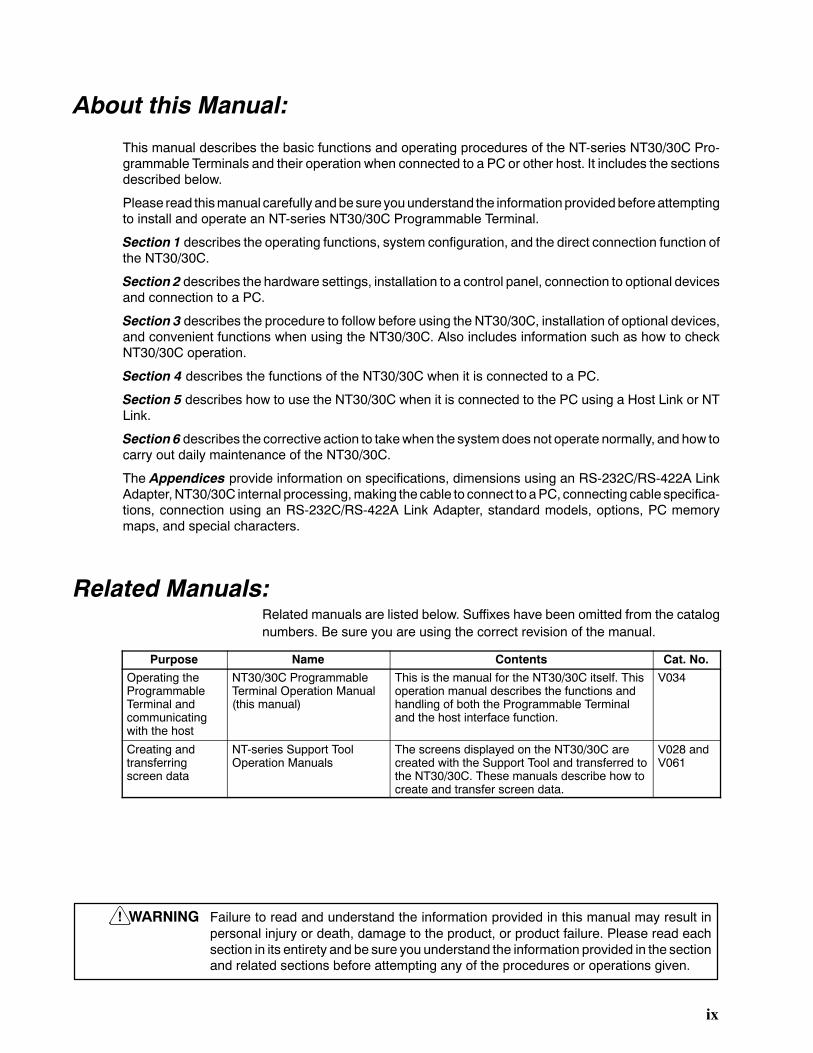
About this Manual:
This manual describes the basic functions and operating procedures of the NT-series NT30/30C Pro-grammable Terminals and their operation when connected to a PC or other host. It includes the sectionsdescribed below.
Please read thismanual carefully andbesure youunderstand the informationprovidedbeforeattemptingto install and operate an NT-series NT30/30C Programmable Terminal.
Section 1 describes the operating functions, system configuration, and the direct connection function ofthe NT30/30C.
Section 2 describes the hardware settings, installation to a control panel, connection to optional devicesand connection to a PC.
Section 3 describes the procedure to follow before using the NT30/30C, installation of optional devices,and convenient functions when using the NT30/30C. Also includes information such as how to checkNT30/30C operation.
Section 4 describes the functions of the NT30/30C when it is connected to a PC.
Section 5 describes how to use the NT30/30C when it is connected to the PC using a Host Link or NTLink.
Section 6 describes the corrective action to takewhen the systemdoes not operate normally, and how tocarry out daily maintenance of the NT30/30C.
The Appendices provide information on specifications, dimensions using an RS-232C/RS-422A LinkAdapter,NT30/30C internal processing,making the cable to connect to aPC, connecting cable specifica-tions, connection using an RS-232C/RS-422A Link Adapter, standard models, options, PC memorymaps, and special characters.
Related Manuals:Related manuals are listed below. Suffixes have been omitted from the catalognumbers. Be sure you are using the correct revision of the manual.
Purpose Name Contents Cat. No.
Operating theProgrammableTerminal andcommunicatingwith the host
NT30/30C ProgrammableTerminal Operation Manual(this manual)
This is the manual for the NT30/30C itself. Thisoperation manual describes the functions andhandling of both the Programmable Terminaland the host interface function.
V034
Creating andtransferringscreen data
NT-series Support ToolOperation Manuals
The screens displayed on the NT30/30C arecreated with the Support Tool and transferred tothe NT30/30C. These manuals describe how tocreate and transfer screen data.
V028 andV061
WARNING Failure to read and understand the information provided in this manual may result inpersonal injury or death, damage to the product, or product failure. Please read eachsection in its entirety and be sure you understand the information provided in the sectionand related sections before attempting any of the procedures or operations given.
!

xi
PRECAUTIONS
This section provides general precautions for using the Programmable Terminal.
The information contained in this section is important for the safe and reliable application of the Programmable Ter-minal. Youmust read this section and understand the information contained before attempting to set up or operate aProgrammable Terminal.
1 Intended Audience xii. . . . . . . . . . . . . . . . . . . . . . . . . . . . . . . . . . . . . . . . . . . . . . . . . . . . . . . . . . .2 General Precautions xii. . . . . . . . . . . . . . . . . . . . . . . . . . . . . . . . . . . . . . . . . . . . . . . . . . . . . . . . . .3 Safety Precautions xiii. . . . . . . . . . . . . . . . . . . . . . . . . . . . . . . . . . . . . . . . . . . . . . . . . . . . . . . . . . .

!
!
3General Precautions
xii
1 Intended AudienceThis manual is intended for the following personnel, who must also have knowl-edge of electrical systems (an electrical engineer or the equivalent).
S Personnel in charge of installing FA systems.
S Personnel in charge of designing FA systems.
S Personnel in charge of managing FA systems and facilities.
2 General PrecautionsThe user must operate the PT according to the performance specifications de-scribed in the operation manuals.
Before using the PT under conditions that are not described in themanual or ap-plying thePT to nuclear control systems, railroad systems, aviation systems, ve-hicles, combustion systems, medical equipment, amusement machines, safetyequipment, and other systems, machines, and equipment that may have a seri-ous influenceon lives and property if used improperly, consult yourOMRON rep-resentative.
Make sure that the ratings and performance characteristics of the PT are suffi-cient for the systems, machines, and equipment, and be sure to provide the sys-tems, machines, and equipment with double safety mechanisms.Thismanual provides information for using theProgrammable Terminal. Be sureto read this manual before attempting to use the software and keep this manualclose at hand for reference during operation.
S If a faultyPT is returned for repairs,write as detailed adescription of the fault aspossible and send the description togetherwith thePT to theOMRONaddressindicated on the back cover of this book.
S When disposing of an NT that is no longer required, be sure to comply with alllocal restrictions that apply to its disposal.
WARNING It is extremely important that Programmable Terminals and related devices beused for the specified purpose and under the specified conditions, especially inapplications that can directly or indirectly affect human life. You must consultwith your OMRON representative before applying Programmable Terminals tothe above mentioned applications.
WARNING Do not use input functions such as PT touch switches for applications wheredanger to human life or serious damage is possible, or for emergency switchapplications.

!
!
3Safety Precautions
xiii
3 Safety PrecautionsRead these safety precautions carefully and make sure you understand thembefore using the Programmable Terminal so that you can use it safely and cor-rectly.
WARNING
S Never attempt repairs,modification or disassembly. You could sustain anelec-tric shock.
S Switch OFF the PT power before changing the backlight. You could sustain anelectric shock if you attempt to change the backlight while power is being sup-plied.
Caution
S Whendisposing of a usedbacklight, complywith all local restrictions that applyto its disposal.
S When replacing the battery, do not allow the battery terminals to touch theboard in the PT.
S If not backedupby thebuilt-in battery, thememory switch settingswill be initial-ized to the values setwith theNT-series Support Tool when the power is turnedOFF. If a message indicating that the battery is low is displayed while the PT isbeing used, replace the built-in battery immediately. For details on how to re-place the battery, refer to Replacing the Battery (page 253).
S Switch OFF the power supply to both the PT and the B7A Interface Unit beforeinstalling the B7A Interface Unit, otherwise the PT or the B7A Interface Unitmay be damaged.
S Switch OFF the power supply to both the PT and the B7A Interface Unit beforechanging DIP switch settings.
S Do not use input functions, such as PT touch switches, for applications wheredanger to human life or serious property damage is possible or for emergencyswitch applications.
S Do not use the expanded I/O functions of the B7A Unit for applications wheredanger to human life or serious property damage is possible or for emergencyswitch applications.
S On unpacking the PT, check its external appearance and confirm that there isno damage. Also confirm that there is no abnormal noise on shaking the PTlightly. The PT may malfunction if it is damaged.
S Duringwork at the panel, be sure that nometal scraps enter thePT.Otherwise,the PT may malfunction.
S The thickness of applicable operation panel is 1.6 mm to 4.8 mm. All fittingsmust be tightened uniformly to a torque of 0.5 to 0.6 N⋅m in order to ensurewater- and dust- resistance. The panelmust not be soiled orwarped, andmustbe able to support an installation that will remain secure and strong.
S Carefully check wiring before switching ON the power.

3Safety Precautions
xiv
S Do not apply an AC power supply across the power supply terminals.
S Use a DC power supply with a low voltage fluctuation.
S When complying with EC low voltage directives use a power supply with rein-forced insulation.
S For the connection to the power supply terminal block, twisted-pair wireswith a2 mm2 or greater cross sectional area andM 3.5 size crimp terminals must beused. Tighten the screws on the terminal block to a torque of 0.8 N⋅cm.Other-wise fire may occur.
S If the DIP switch settings have been changed while power was supplied to thePT, reset the power to the PT. The changes with the DIP switch become effec-tive only after the power supply is reset.
S Before switchingON the power for the first time, set pin 6 of DIP switch SW2onthe PT to ON (it is set to OFF on shipping). If it is left OFF,messages will not bedisplayed normally.
S Press the Abort touch switch on the PT when screen data transmission hasbeen completed. Unless this touch switch is pressed, the screen data will notbe correctly registered. If the Abort touch switch is pressed during transmis-sion, the screen data will not be correctly registered.
S Check the operation of screen data and ladder program thoroughly before ac-tually using them.
S Press touchswitcheswitha forceof nogreater than30N.Applyinghigher forcemay cause glass to break, resulting in injuries or preventing operation.
S Do not press touch switches carelessly while the backlight is OFF or whilenothing is displayed on the screen. The system may operate unpredictably.Press touch switches only after confirming system safety.
S As far as possible, disconnect all devices connected to theoutput terminals be-fore executing the output check. Otherwise, each time an output terminalcomes ON during the check operation, the outputs to the devices may be acti-vated.

1
SECTION 1Functions of the NT30/30C
This section gives the operation examples and characteristics of theNT30/30C so that youwill understand the applications ofthe NT30/30C.
1-1 Role and Operation of NT30/30C 2. . . . . . . . . . . . . . . . . . . . . . . . . . . . . . . . . . . . . . . . . . . .1-1-1 Operation of an NT30/30C at an FA Production Site 2. . . . . . . . . . . . . . . . . . . . . .1-1-2 Operations of NT30/30C 3. . . . . . . . . . . . . . . . . . . . . . . . . . . . . . . . . . . . . . . . . . .
1-2 Functions of NT30/30C 4. . . . . . . . . . . . . . . . . . . . . . . . . . . . . . . . . . . . . . . . . . . . . . . . . . .1-2-1 Features 4. . . . . . . . . . . . . . . . . . . . . . . . . . . . . . . . . . . . . . . . . . . . . . . . . . . . . . . .1-2-2 Comparison between NT30 and NT30C 4. . . . . . . . . . . . . . . . . . . . . . . . . . . . . . .1-2-3 Principal Functions of NT30/30C 5. . . . . . . . . . . . . . . . . . . . . . . . . . . . . . . . . . . .1-2-4 Displays 6. . . . . . . . . . . . . . . . . . . . . . . . . . . . . . . . . . . . . . . . . . . . . . . . . . . . . . . .
1-3 System Configuration 7. . . . . . . . . . . . . . . . . . . . . . . . . . . . . . . . . . . . . . . . . . . . . . . . . . . . .1-4 Communications Using the Direct Connection Function 8. . . . . . . . . . . . . . . . . . . . . . . . . .
1-4-1 Direct Connection Function 8. . . . . . . . . . . . . . . . . . . . . . . . . . . . . . . . . . . . . . . . .1-4-2 NT Link 9. . . . . . . . . . . . . . . . . . . . . . . . . . . . . . . . . . . . . . . . . . . . . . . . . . . . . . . .1-4-3 Functions of the Allocated Bits and Words 9. . . . . . . . . . . . . . . . . . . . . . . . . . . . .
1-5 Before Operating 13. . . . . . . . . . . . . . . . . . . . . . . . . . . . . . . . . . . . . . . . . . . . . . . . . . . . . . . .

1-1SectionRole and Operation of NT30/30C
2
1-1 Role and Operation of NT30/30CNT30/30C is aProgrammableTerminal used to display and transmit the informa-tion in an FA site. The following gives a general description of the role and opera-tion of the NT30/30C for those who use a Programmable Terminal (PT) for thefirst time.
1-1-1 Operation of an NT30/30C at an FA Production Site
The NT30/30C can be used to display real-time information about the systemand equipment operating status, etc.
Production Control 1994/1/25
Today’s target
NT30 NT30C
54.5 %
441 units
Product
Current Production
% achieved
305 units
560 units
275 units
63.0 %
Messages TheNT30/30Ccanbeused towarnof systemor equipment failures andpromptsthe appropriate remedial action.
-Assembly line B
is defective.
AlarmPositioning pin
Panel Switch Functions Setting touchswitcheson theNT30/30Ccanbeset up toallowworkers touse theNT30/30C as a control panel. Production data input to the NT30/30C can betransmitted to a PC.
Electroplating Control
Transport
Clamp UnClamp
Production Line StatusMonitoring
1-1SectionRole and Operation of NT30/30C
3
1-1-2 Operations of NT30/30C
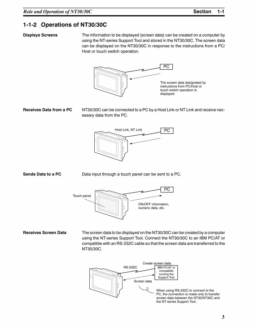
Displays Screens The information to be displayed (screen data) can be created on a computer byusing the NT-series Support Tool and stored in the NT30/30C. The screen datacan be displayed on the NT30/30C in response to the instructions from a PC/Host or touch switch operation.
The screen data designated byinstructions from PC/Host ortouch switch operation isdisplayed.
PC
Receives Data from a PC NT30/30C can be connected to a PC by a Host Link or NT Link and receive nec-essary data from the PC.
Host Link, NT Link PC
Sends Data to a PC Data input through a touch panel can be sent to a PC.
ON/OFF information,numeric data, etc.
Touch panel
PC
Receives Screen Data The screen data to be displayed on theNT30/30C can be created by a computerusing the NT-series Support Tool. Connect the NT30/30C to an IBM PC/AT orcompatible with an RS-232C cable so that the screen data are transferred to theNT30/30C.
When using RS-232C to connect to thePC, the connection is made only to transferscreen data between the NT30/NT30C andthe NT-series Support Tool.
Create screen data.IBM PC/AT orcompatiblerunning theSupport Tool
Screen data
RS-232C

1-2SectionFunctions of NT30/30C
4
1-2 Functions of NT30/30C
The NT30/30C has the following features.
1-2-1 Features
Downsized Body
• Slim body (50 mm or less in the panel).
• The communication cable connectors are housed in the Unit so that they donot protrude from the Unit.
• The same connector is used to connect to the theSupport Tool and to the host.
Construction Best Suited to the FA Environment• Easy-to-read screen even in direct sunlight.
• The panel is a LCD panel with white/red backlight for the NT30, and an STNcolor LCD panel with backlight for the NT30C.
• Its backlight unit and battery can be replaced at the operation site.
•Waterproofed to a standard equivalent to IP65.
Wide angle of visibility,35_
320 dots
240 dots
POWER
RUN
Touch Switch Operation The System Menu can be displayed by using the touch switches located in fourcorners of the screen.
Existing screen data and user programs are compatible. (Modification requiredaccording to screen size.)
1-2-2 Comparison between NT30 and NT30C
Twomodels are available: TheNT30 is capable of versatile graphic displays andtheNT30Cprovides the same features, but is also capable of color displays. Thedifferences between the NT30 and NT30C are listed below.
Function NT30 NT30C
Model NT30-ST131-E (Beige)NT30-ST131B-E (Black)
NT30C-ST141-E (Beige)NT30C-ST141B-E (Black)
Display panel Monochrome LCD type(with white/red backlight)
STN color LCD type(with backlight)
Compatibility withNT612G/610C

1-2SectionFunctions of NT30/30C
5
1-2-3 Principal Functions of NT30/30CThe following are the principal functions of the NT30/30C.
Data InputTouch Switches
Data can be input by simply touchingthe screen. There are various touchswitch functions, such as those forsending input data to the PC.
Pop-up WindowsA window overlaying the currently dis-played screen can be opened andclosed by pressing a touch switch. Inaddition to fixed displays, numeric keysand character keys can be set insidethe window. The window need beopened only when input is required, toenable effective screen usage.
Numeric Values/CharacterStrings
Touch switch keys and expanded I/Oon a B7A Unit can be allocated numericvalues or character strings so thatthese values and character strings canbe input at the operation site or evenwritten onto the numeric or characterstring table and sent to the PC. It isalso possible to disable inputs from thePC.
Data DisplaysCharacter Displays
Characters of various sizes can be displayed. Characters can be flashed and high-lighted.
Figure DisplaysSolid lines, squares, polygons, circles, circular arcs, and fan shapes can be dis-played. They can also be painted with various patterns, flashed, or highlighted.
Memory Data DisplaysEntries in the character string memory table or numeral table can be displayed. Thememory table contents can be changed from the PC.
Graph DisplaysNot only bar graphs, but also broken line graphs and trend graphs can be displayedusing the numeral table.
Lamp DisplaysLamps can be turned ON or flashed from the PC.
Alarm List DisplaysIn response to the status of PC bits, warning messages can be automatically listed.When and how many times the messages appeared can also be displayed.
Data OutputBuzzer
A built-in buzzer can be sounded.
Screen PrintingA hard copy of the screen may beprinted to the printer connected tothe NT30/30C.
CommunicationsThe NT30/30C communicateswith PC through a Host Inter-face Unit or NT Link so thatdata may be received from PCor information entered fromtouch switches may be sent tothe PC.
Expanded I/O Functions on B7A UnitsThe NT30/30C can receive a switching input from a B7AUnit, and turns ON/OFF the output.S A B7A Interface Unit is required to connect a B7A Unit.
SystemSystem Functions
System settings and maintenance can be performed by selecting from system me-nus displayed on the screen.
Creating Screen DataScreen data created by using the NT-series Support Tool on a personal computercan be transferred and stored in the built-in image data memory.
System Program InstallationUsing the System Installer (purchased separately), the system programs for theNT30 and NT30C can be replaced.
1-2SectionFunctions of NT30/30C
6
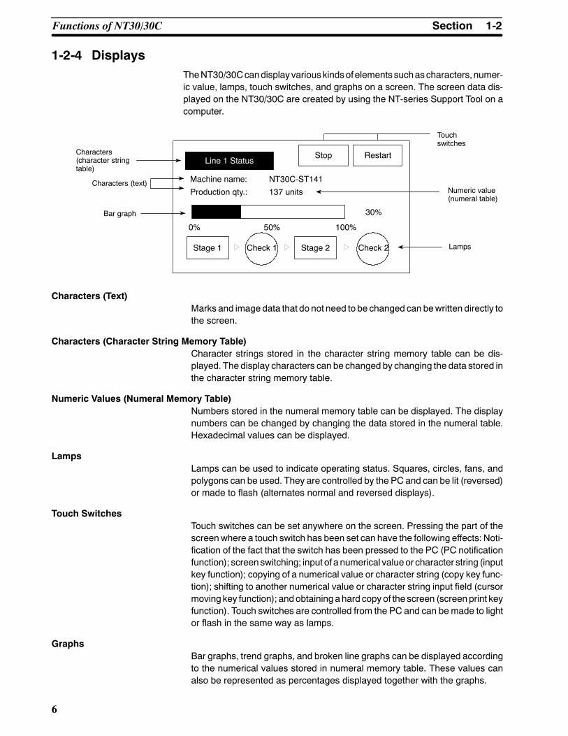
1-2-4 DisplaysTheNT30/30Ccandisplayvariouskindsofelements suchascharacters,numer-ic value, lamps, touch switches, and graphs on a screen. The screen data dis-played on the NT30/30C are created by using the NT-series Support Tool on acomputer.
Line 1 StatusStop Restart
Machine name: NT30C-ST141
Production qty.: 137 units
0% 50% 100%
30%
Stage 1 Stage 2 Lamps
Numeric value(numeral table)
Touchswitches
Characters (text)
Characters(character stringtable)
Bar graph
Check 1 Check 2
Characters (Text)Marks and image data that do not need to be changed can bewritten directly tothe screen.
Characters (Character String Memory Table)Character strings stored in the character string memory table can be dis-played. The display characters can be changed by changing the data stored inthe character string memory table.
Numeric Values (Numeral Memory Table)Numbers stored in the numeral memory table can be displayed. The displaynumbers can be changed by changing the data stored in the numeral table.Hexadecimal values can be displayed.
LampsLamps can be used to indicate operating status. Squares, circles, fans, andpolygons can be used. They are controlled by the PC and can be lit (reversed)or made to flash (alternates normal and reversed displays).
Touch SwitchesTouch switches can be set anywhere on the screen. Pressing the part of thescreenwhere a touch switch has been set can have the following effects: Noti-fication of the fact that the switch has been pressed to the PC (PC notificationfunction); screenswitching; input of a numerical valueor character string (inputkey function); copying of a numerical value or character string (copy key func-tion); shifting to another numerical value or character string input field (cursormoving key function); andobtaining ahard copy of the screen (screenprint keyfunction). Touch switches are controlled from the PC and can be made to lightor flash in the same way as lamps.
GraphsBar graphs, trend graphs, and broken line graphs can be displayed accordingto the numerical values stored in numeral memory table. These values canalso be represented as percentages displayed together with the graphs.

Reference
1-3SectionSystem Configuration
7
1-3 System ConfigurationThis section gives the basic configuration of a system that uses an NT30/30C.Use an RS-232C cable or an RS-422A cable to connect to a PC. Refer to themanuals for individual devices for information on devices other than theNT30/30C in the system.
OMRON PCControls the NT30/30C as required while controlling machines andmonitoring the production line.Host Link: C-series PC, CVM1/CV-series PC, SRM1
NT30/30C can be connected to CPU Units, Host LinkUnits, and an SRM1. Connection to some models of CPUUnit and some models of the SRM1, however, is notpossible (see pages 23 and 40).
NT Link: CPM1, CQM1, C200HS, C200HX/HG/HE,CVM1/CV-series PC, SRM1NT30/30C can be connected to CPU Units and theSRM1. Connection to some models of CPU Unit andsome models of the SRM1, however, is not possible (seepage 56).
NT30/30CProvides displays of production linemonitoring information and instructions to theoperation site and notifies switch ON/OFFstatus and numeric value inputs to the PC.
NT-series Support Tool
Computer (NT-series Support Tool)Connected to the NT30/30C as required and used to transferthe NT30/30C screens and make settings for the NT30/30C.Computer: IBM PC/AT or compatibleSoftware: NT-series Support Tool
RS-232C cable(for Host Link)(Max. 15 m)or RS-422A cable(for Host Link)(Max. 500 m)
NT-B7A16 B7AInterface Unit
B7A UnitA B7A Unit can be connected to expand I/O.
Bar code readerEnables reading of barcodes as character strings.(Cannot be used withmemory link.)
PrinterThe screen display of theNT30/NT30C can beprinted out.
Refer to 3-5 Setting Communications with the PC Using Memory Switches(page83) for settingprocedures. It is impossible to connectapersonal computerrunning the NT-series Support Tool and a PC at the same time.Typical optional devices for the NT30/30C include the following.B7A Interface Unit NT-B7A16Backlight (spare) NT30-CFL01 (for NT30)
NT30C-CFL01 (for NT30C)Protective Sheets NT30-KBA04 (5 sheets/pack)Battery C500-BAT08

1-4SectionCommunications Using the Direct Connection Function
8
1-4 Communications Using the Direct Connection Function
1-4-1 Direct Connection Function
Thecommunicationsmethodappliedbetween theNTand thePC is either aHostLink or NT Link.
The NT30/30C can be used to access data for the display or to allocate the bitsandwords for storing input data in essentially any area in the PC. TheNT30/30Ccandirectlywrite and read theallocatedbits andwords to change thedisplay ele-ments, control operating status, and notify status.
This function is called the direct connection function. TheNT30/30C is designedspecially for use with a direct connection.
The bits and words allocated by the direct connection function are called allo-cated bits and allocated words.
A direct connection enables reading the data to be displayed on the NT30/30Cfrom amemory area in the PC and writing it to a memory table in the NT30/30C.Also, the data input at the NT30/30C can be written to a PC memory area. TheNT30/30C screen status can be switched according to PC memory area data,and NT30/30C status data can be written to a PC memory area.
NT30/30C PC
DM Area IR/CIO Area
AR Area Timer/CounterArea
Features• The bits and words used to access operating status andwork instructions andthose for storing input data can be allocated in almost any part of PC I/O me-mory. Bits and words in the PC are accessed from memory table entries.
• The NT30/30C can directly access PC bit and word data so that it can be con-nected to a PCwithout changing the PC program that controls the current pro-duction line.
• The area to control and notify theNT30/30C status, including display screens,display/no display status, and buzzers, can be allocated in almost any part ofPC I/O memory.
The direct connection function allows theNT30/30C to directly read andwrite al-most all bits and words in the PC and to automatically change the NT30/30Cscreen display. This function can reduce the load on the PC to improve the pro-gram development efficiency of the PC.

1-4SectionCommunications Using the Direct Connection Function
9
1-4-2 NT Link
The NT Link is a new communications method between the PT and a PC.
The NT Link uses the direct connection function and can execute high-speedcommunications with a CPM1, CPM2A, CPM2C, CQM1, CQM1H, C200HS,C200HX/HG/HE(-Z), CS1-series, CVM1, CV-series, or SRM1CPUUnit (built-inHost Link).
Features of the NT Link• High-speed communications with specific types of PCs can be executed.
•Writing in units of bits to the PCmemory area is possible (except the DMArea.
.This enables the bit in a word data to which a touch switch has been allocatedto be used for other purposes (e.g., to control a lamp).
• This can be used evenwhen the PC is in RUNmode. (WithHost Link, if the PCis in RUN mode, the NT30/NT30C switches the mode to MONITOR mode.)
Either the NT Link or the Host Link can be used for connection without changingthe NT30/30C screen data or the PC program.
1-4-3 Functions of the Allocated Bits and Words
Elements displayed on theNT30/30Cand theNT30/30C status can be allocatedto the bits and words of the PC. By changing the contents of the bits and words,the NT30/30C can be controlled by the PC. It is also possible to send data to thePC by pressing the touch switches on the NT30/30C.
S Controlling the NT30/30C by a PC
The following NT30/30C functions can be controlled by a PC.
Screens: Display of designated screens, confirmationof screen numbers, etc.
Memory tables: Writing to amemory table entry, copying froma memory table entry to another memorytable entry, etc.
Lamps and touch switches: Display instructions, confirmation of displaystatus, etc.
System control: Buzzer ON/OFF, display/no display status,screen printing, and other NT30/30C sta-tuses
S Notifying from the NT30/30C to a PC
Data in the NT30/30C is sent to a PC when a touch switch is pressed. The fol-lowing types of data can be sent to the PC.
• NT30/30C status
• Touch switch status
• Numeric values and character strings input with numeral/character stringsetting functions using touch switches.
• Changes in amemory table entry after copying betweenmemory table en-tries

1-4SectionCommunications Using the Direct Connection Function
10
Display ElementsS Lamps (page 151)
Allocated to: Bits
Lamp #1 (IR/CIO 000100)
Lamp #2 (IR/CIO 000101)
Switch 1: ON (IR/CIO 000100)
Switch 2: OFF (IR/CIO 000101)
NT30/30C PC
Lit
Unlit
The PC’s bit status can be displayed by lamps on the NT30/30C.
The lamp lights or flashes when the PC’s bit status (i.e., the lamp bit) is ON (1),and goes OFF when it is OFF (0).
Image/library lamps can also be created to switch the displayed image or li-brary data according to the ON (1)/OFF (0) status of the lamp bit.
S Touch Switches (page 154)
Allocated to: Bits
Touch switch #12IR/CIO 009012
IR/CIO 009012: ON
NT30/30C PC
The PC bit allocated for the touch switch turns ON (1) and OFF (0) when thetouch switch is pressed to notify the PC of the status of the touch switch.
S Numeral Memory Table (page 138)
Allocated to: Words
Numeral memorytable entry 1 (TIM003)
Numeral memory table entry 150 (IR/CIO 0005)
NT30/30C PC
The numeral memory table is allocated to words in the PC. If word contentschange when corresponding numeral memory table entry is displayed on thescreen, the value on the screen will also change, enabling the contents ofwords to be easily monitored.
Reading and writing are executed so that the contents of allocated words arekept the same as those of the numeral memory table entries.

1-4SectionCommunications Using the Direct Connection Function
11
S Character String Memory Table (page 136)
Allocated to: Words
Character string memory table entry 1Number of words allocated: 3 wordsFirst word: DM0100
NT30/30C PC
(“a”, “b”)(“c”, “d”)(“e”, “f”)
The character stringmemory table is allocated to words in the PC. If word con-tents change when the corresponding character string memory table entry isdisplayed on the screen, the value on the screen will also change, enablingmessages to be easily displayed.
Reading and writing are executed so that the contents of allocated words arekept the same as those of the character string memory table entries.
S Alarm List (Bit Memory Table) (pages 140 and 180)
Allocated to: Bits
NT30/30C PC
Material low
Material low
IR/CIO 010009 1
IR/CIO 010009
Character string memorytable entry 120
Bit memory table entry 23
Character string memorytable entry 120
Alarm list
When the corresponding PC bit turns ON (1), the contents of the characterstringmemory table entry registered for the bitmemory table entry is displayedin the alarm list.When the bit returns to theOFF (0) status, the character stringmemory table entry display is automatically cleared.

1-4SectionCommunications Using the Direct Connection Function
12
PT Status Control Area (PC to NT30/30C)ThePTStatusControl Area is used to control theNT30/30Cstatus.Whendata iswritten to this area in the PC, the NT30/30C reads the contents and operates ac-cording to the contents.
Example of PT Status Control Area Application
Whendata is written to thePTStatusControl Area, theNT30/30Cwill operate asillustrated below (page 191).
Screen 3display
Continuousbuzzer sound
Copy
Numeral memory table entry 50
Numeral memory table entry 7
PT Status Control Area
Screen switch settingMemory table entryCopy settingPT status control bits
NT30/30C PC
PT Status Notify Area (NT30/30C to PC)The PT Status Notify Area is used to notify the PC of changes in the NT30/30Cstatus. When a change is made in the NT30/30C status, the change is written tothis area in the PC. By reading the data from the area, the NT30/30C status canbe checked from the PC.
Example of PT Status Notify Area Application
When a change is made in the NT30/30C status, the change will be indicated inthe PT Status Notify Area as illustrated below (page 193).
Numeral memory table entry 13PT Status Notify Area
Content update memory table entry
Allocated word (numeral table entry 13)
PT status
StartStart + 1
NT30/30C PC
12345678
12345678
Currently display screen12345678

Caution
1-5SectionBefore Operating
13
1-5 Before OperatingUse the procedure given below to start the NT30/30C.
PC NT30/30C NT-series Support Tool
Check and changethe PC settings.
S For the Host Link, referto page 27 (RS-232C),page 40 (RS-422A)and the manuals forthe Host Link Unit andProgramming Devices.
S For the NT Link,refer to page 56.
Connect to theNT30/30C.
Create the PCprogram.
Set the DIP switch.
(page 18)
Install to the opera-tion panel.
(page 19)
Connect the powersupply.
(page 20)
Connect to the PC.
S (Host Link:page 25 (RS-232C)page 42 (RS-422A))
S (NT Link: page 56)
Check the settingsand communications.
Transfer thescreen data.(page 89)
(Refer to Section 4 andthe manuals for theNT-series Support Tool.)
Create the screens.
Start operation.
Install NT-seriesSupport Tool on thecomputer.
(Refer to the manualsfor the NT-seriesSupport Tool.)
Be sure to confirm that correct operation is possiblewith the screendata and thehost program before actual operation.
Reference 1. Use the System Installer provided with the NT-series Support Tool for Win-dows.
2. Use the NT-series Support Tool for Windows.

1-5SectionBefore Operating
14
Refer to the following manuals for the product information.
Product Manual Title Cat No.
System Installer NT-series Support Tool for Windows Operation Manual V061-E1-j
NT-series Support Tool NT-series Support Tool Operation Manual V028-E1-jpp
NT-series Support Tool for Windows Operation Manual V061-E1-j
PCs SYSMAC CPM1 Operation Manual W262-E1-j
SYSMAC CPM1A Operation Manual W317-E1-j
SYSMAC CPM2A Operation Manual W352-E1-j
SYSMAC CPM2C Operation Manual W356-E1-j
SYSMAC C20H/C28H/C40H/C60H Programming Manual W176-E1-j
SYSMAC C200H Operation Manual (CPU01-E/03-E/11-E) W130-E1-j
SYSMAC C200H Operation Manual (CPU21-E/23-E/31-E) W217-E1-j
SYSMAC C200HS Operation Manual W235-E1-j
SYSMAC C200HS Installation Guide W236-E1-j
SYSMAC C200HX/HG/HE-CPUjj-E/ZE Installation Guide W302-E1-j
SYSMAC C200HX/HG/HE Operation Manual W303-E1-j
SYSMAC C1000H/C2000H Operation Manual W140-E1-j
SYSMAC C200HX/HG/HE-CPUjj-ZE Operation Manual W322-E1-j
SYSMAC CQM1 Reference Manual W228-E1-j
SYSMAC CQM1H Operation Manual W363-E1-j
SYSMAC CV500/CV1000/CV2000 Operation Manual: LadderDiagrams* For a PC of the CVM1 Series, refer to the SYSMACCV500/CV1000/CV2000 Operation Manual.
W202-E1-j
SYSMAC CS1-series Operation Manual W339-E1-j
SYSMAC CS1-series Programming Manual W340-E1-j
CompoBus/SMaster Control Unit
SRM1 Operation Manual W318-E1-j
Programming Devices SYSMAC C-series and CVM1 PCs SYSMAC Support SoftwareOperation Manual: C-series PCs
W248-E1-j
SYSMAC C-series and CVM1 PCs SYSMAC Support SoftwareOperation Manual: CVM1 PCs
W249-E1-j
CX-Programmer Operation Manual ---
Host Link Unit SYSMAC C-series Host Link Unit Operation Manual W143-E1-j
SYSMAC CVM1/C-series Host Link Operation Manual W205-E1-j

15
SECTION 2Hardware Settings and Connections
This section describes the settings of the NT30/30C, connections to a PC, and other hardware settings.
2-1 Description of Parts and Settings 16. . . . . . . . . . . . . . . . . . . . . . . . . . . . . . . . . . . . . . . . . . . .2-1-1 Description of Parts 16. . . . . . . . . . . . . . . . . . . . . . . . . . . . . . . . . . . . . . . . . . . . . . .2-1-2 DIP Switch Settings 18. . . . . . . . . . . . . . . . . . . . . . . . . . . . . . . . . . . . . . . . . . . . . . .
2-2 Installation 19. . . . . . . . . . . . . . . . . . . . . . . . . . . . . . . . . . . . . . . . . . . . . . . . . . . . . . . . . . . . .2-2-1 Installation to the Operation Panel 19. . . . . . . . . . . . . . . . . . . . . . . . . . . . . . . . . . . .2-2-2 Power Supply Connection 20. . . . . . . . . . . . . . . . . . . . . . . . . . . . . . . . . . . . . . . . . .2-2-3 Ground Wire Connection 21. . . . . . . . . . . . . . . . . . . . . . . . . . . . . . . . . . . . . . . . . . .
2-3 Connecting to the Support Tool 21. . . . . . . . . . . . . . . . . . . . . . . . . . . . . . . . . . . . . . . . . . . . .2-4 Installing the System Program 22. . . . . . . . . . . . . . . . . . . . . . . . . . . . . . . . . . . . . . . . . . . . . .2-5 Connection to a PC by Host Link via RS-232C 23. . . . . . . . . . . . . . . . . . . . . . . . . . . . . . . . .
2-5-1 Compatible PCs 23. . . . . . . . . . . . . . . . . . . . . . . . . . . . . . . . . . . . . . . . . . . . . . . . . .2-5-2 Connecting the NT30/30C 25. . . . . . . . . . . . . . . . . . . . . . . . . . . . . . . . . . . . . . . . . .2-5-3 PC Switch Settings 27. . . . . . . . . . . . . . . . . . . . . . . . . . . . . . . . . . . . . . . . . . . . . . . .
2-6 Connection to a PC by Host Link via RS-422A 40. . . . . . . . . . . . . . . . . . . . . . . . . . . . . . . . .2-6-1 Compatible PCs 40. . . . . . . . . . . . . . . . . . . . . . . . . . . . . . . . . . . . . . . . . . . . . . . . . .2-6-2 Parts Required for Connection 42. . . . . . . . . . . . . . . . . . . . . . . . . . . . . . . . . . . . . . .2-6-3 Method for Connection 42. . . . . . . . . . . . . . . . . . . . . . . . . . . . . . . . . . . . . . . . . . . .2-6-4 Connector Specifications and Wiring for Each Unit 43. . . . . . . . . . . . . . . . . . . . . .2-6-5 PC Switch Settings 48. . . . . . . . . . . . . . . . . . . . . . . . . . . . . . . . . . . . . . . . . . . . . . . .
2-7 Connection to a PC by the NT Link 56. . . . . . . . . . . . . . . . . . . . . . . . . . . . . . . . . . . . . . . . . .2-7-1 Compatible PCs 56. . . . . . . . . . . . . . . . . . . . . . . . . . . . . . . . . . . . . . . . . . . . . . . . . .2-7-2 Connecting the NT30/30C 58. . . . . . . . . . . . . . . . . . . . . . . . . . . . . . . . . . . . . . . . . .2-7-3 PC Switch Settings (RS-232C at PC Side) 59. . . . . . . . . . . . . . . . . . . . . . . . . . . . . .2-7-4 PC Switch Settings (RS-422A at PC Side) 61. . . . . . . . . . . . . . . . . . . . . . . . . . . . . .
2-8 Connecting a Printer 63. . . . . . . . . . . . . . . . . . . . . . . . . . . . . . . . . . . . . . . . . . . . . . . . . . . . . .2-8-1 How to Connect 64. . . . . . . . . . . . . . . . . . . . . . . . . . . . . . . . . . . . . . . . . . . . . . . . . .
2-9 Connection of Expanded I/O 64. . . . . . . . . . . . . . . . . . . . . . . . . . . . . . . . . . . . . . . . . . . . . . .2-9-1 Connectable B7A Units 64. . . . . . . . . . . . . . . . . . . . . . . . . . . . . . . . . . . . . . . . . . . .2-9-2 B7A Interface Unit Specifications 65. . . . . . . . . . . . . . . . . . . . . . . . . . . . . . . . . . . .2-9-3 B7A Interface Unit Part Names 66. . . . . . . . . . . . . . . . . . . . . . . . . . . . . . . . . . . . . .2-9-4 Installing the B7A Interface Unit 66. . . . . . . . . . . . . . . . . . . . . . . . . . . . . . . . . . . . .2-9-5 B7A Interface Unit Settings 67. . . . . . . . . . . . . . . . . . . . . . . . . . . . . . . . . . . . . . . . .2-9-6 Connecting the B7A Unit to the B7A Interface Unit 67. . . . . . . . . . . . . . . . . . . . . .

Caution
Reference
2-1SectionDescription of Parts and Settings
16
2-1 Description of Parts and SettingsBefore getting to the operation, confirm the names and functions of parts. Alsoset the DIP switch on the NT30/30C.
On unpacking the NT30/30C, check its external appearance and confirm thatthere is no damage. Also confirm that there is no abnormal noise on shaking theUnit lightly. The product may malfunction if it is damaged.
2-1-1 Description of Parts
Front View
RUN indicatorS Lit in green while the PTis in the RUN mode.S Lit in orange or red whenthe battery is low (orangein the RUN mode, red inother modes)
POWER indicatorLit when the power issupplied.
DisplayThe NT30 has a monochrome LCD screenwith a white/red backlight, and the NT30Chas an STN color LCD screen. The wholearea of the screen is a touch panel thatworks as an input device.
POWER
RUN
The NT30/30C comes in two body colors.
NT30 NT30C Body Color
NT30-ST131-E NT30C-ST141-E BeigeNT30-ST131B-E NT30C-ST141B-E Black
2-1SectionDescription of Parts and Settings
17
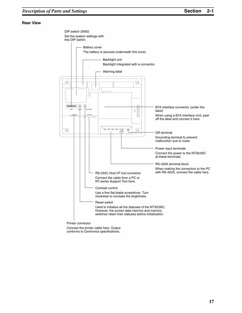
Rear View
RS-422A terminal blockWhen making the connection to the PCwith RS-422A, connect the cable here.
Power input terminalsConnect the power to the NT30/30Cat these terminals.
24 VDC+
PRINTER RS-232C
SW2 RESET --CONTRAST
SDA SDB RDA RDB
Battery coverThe battery is secured underneath this cover.
B7A interface connector (under thelabel)When using a B7A Interface Unit, peeloff the label and connect it here.
Backlight unitBacklight integrated with a connector.
Printer connectorConnect the printer cable here. Outputconforms to Centronics specifications.
Reset switchUsed to initialize all the statuses of the NT30/30C.However, the screen data memory and memoryswitches retain their statuses before initialization.
GR terminalGrounding terminal to preventmalfunction due to noise
DIP switch (SW2)Set the system settings withthis DIP switch.
RS-232C Host I/F tool connectorConnect the cable from a PC orNT-series Support Tool here.
Contrast controlUse a fine flat-blade screwdriver. Turnclockwise to increase the brightness.
Warning label

2-1SectionDescription of Parts and Settings
18
2-1-2 DIP Switch SettingsSet theNT30/30Coperation statuswith theDIP switch located in the bottom rightcorner on the rear side of the body.
24 VDC+
PRINTER RS-232C
SW2 RESET --CONTRAST
SDA SDB RDA
RDB
ON
1 2 3 4 5 6 7 8
Pin Function
1 Not used.
ON
[OFF]
2 Memory protect
ON Data cannot be written to the screen data memory, and screendata transmission and initialization of the screen data memoryare not possible.
[OFF] Screen data transmission and screen data memory initializationare not possible.
3 Switching to the System Menu enabled/disabled
ON The System Menu cannot be displayed. If an error occurs dur-ing a start-up, the System Menu will be automatically displayed.However, RUN Mode cannot be entered.
[OFF] The System Menu can be displayed.
4 Screen data initialize effective/ineffective
ON The NT30/30C will start in a special RUN mode in which thescreen data memory is initialized. When it is started, thememory initialization menu will be displayed. For the initializa-tion procedure, refer to 3-4 Initializing Memory (page 78).
[OFF] The NT30/30C will start in normal RUN mode.
5 Not used.
ON
[OFF]
6 [ON] When you set the DIP switch pin 7 ON, NT-series SystemInstaller messages are displayed in English.
OFF Messages are displayed in Japanese
7 System installation effective/ineffective
ON System program installation is effective (special mode) at thetime when the power turn ON.
[OFF] Starts normal RUN mode.
8 Terminator setting when using RS-422A
ON When connecting to the PC with RS-422A
[OFF] When connecting to the PC with RS-232C
[ ] indicates factory setting.

Caution
Reference
Correct use
Caution
2-2SectionInstallation
19
If the DIP switch settings have been changed when the NT30/30C is powered,reset the power to the NT30/30C. The changes with the DIP switches becomeeffective only after the power supply is reset. Before switchingON the power forthe first time, set DIP switch pin 6 of theNT30/30C toON (they are set toOFFonshipping). If they are left OFF, messages will not be displayed normally.
In addition to the DIP switch settings, set also the host communications, port,baud rate, etc., in the memory switches. For these settings, refer to 3-5 Settingthe Conditions of Communications with the PC by Using the Memory Switches(page 83).
2-2 Installation
Install the NT30/30C to the operation panel and connect the power to theNT30/30C as described below.
S Do not install the NT30/30C at sites subject to the following conditions.Otherwise, the product may malfunction.- Severe temperature variations
- Temperatures or humidities outside the ranges stated in the specifications
- High humidity, condensation
- Splashing chemical agents
- Severe oil splashing
- Corrosive or flammable gases
- Strong vibrations or shocks
- Direct exposure to wind and rain (outdoor sites)
- Strong ultra-violet irradiation
S Take adequate measures to ensure shielding if the NT30/30C is used at alocation subject to any of the following conditions.Otherwise, the productmaymalfunction.- Static electricity, or noise from other equipment
- Strong electromagnetic fields
- Nearby power cables
- Potential exposure to radioactivity
2-2-1 Installation to the Operation Panel
The NT30/30C is mounted on an operation panel by embedding it in the panel.
Use the panel fittings and tools included in the product package and follow theprocedure below.
S During work at the panel, take care to ensure that no metal scraps enter theUnit. Otherwise, the product may malfunction.
S The thickness of applicable operation panel is 1.6 mm to 4.8 mm. All fittingsmust be tightened uniformly to a torque of 0.5 to 0.6 N⋅m in order to ensurewater- anddust-resistance. Thepanelmust not be soiled orwarped, andmustbe able to support an installation that will remain secure and strong.
Caution
2-2SectionInstallation
20
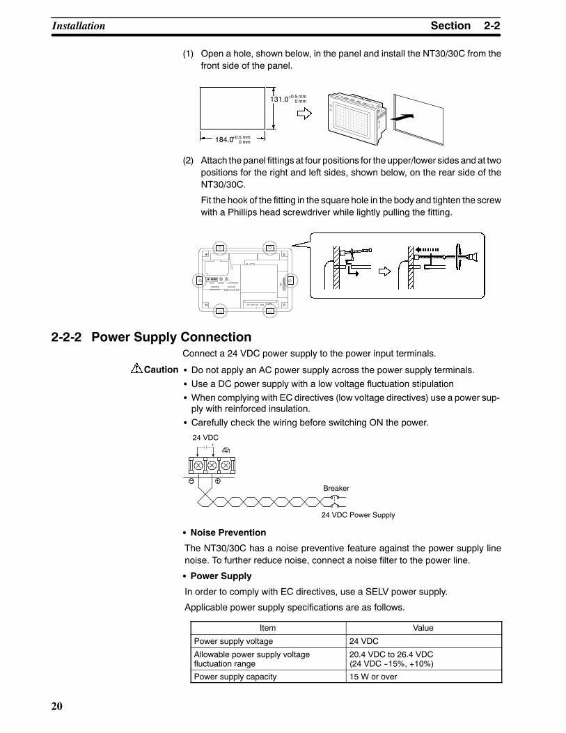
(1) Open a hole, shown below, in the panel and install the NT30/30C from thefront side of the panel.
131.0
184.0
+0.5 mm0 mm
+0.5 mm0 mm
(2) Attach the panel fittings at four positions for the upper/lower sides and at twopositions for the right and left sides, shown below, on the rear side of theNT30/30C.
Fit the hook of the fitting in the square hole in the body and tighten the screwwith a Phillips head screwdriver while lightly pulling the fitting.
RDB 24 VDC
PRINTER RS-232C
SW2 RESET --CONTRAST
SDA SDB RD
A
2-2-2 Power Supply ConnectionConnect a 24 VDC power supply to the power input terminals.
S Do not apply an AC power supply across the power supply terminals.S Use a DC power supply with a low voltage fluctuation stipulationS When complying with EC directives (low voltage directives) use a power sup-ply with reinforced insulation.
S Carefully check the wiring before switching ON the power.
+24 VDC
Breaker
24 VDC Power Supply
S Noise Prevention
The NT30/30C has a noise preventive feature against the power supply linenoise. To further reduce noise, connect a noise filter to the power line.
S Power Supply
In order to comply with EC directives, use a SELV power supply.
Applicable power supply specifications are as follows.
Item Value
Power supply voltage 24 VDC
Allowable power supply voltagefluctuation range
20.4 VDC to 26.4 VDC(24 VDC --15%, +10%)
Power supply capacity 15 W or over

Caution
Correct use
2-3SectionConnecting to the Support Tool
21
S Parts Used for Connection
S For the connection to the power supply terminal block, twisted wires of 2mm2
or greater cross sectional area and M 3.5 size crimp terminals must be used.Tighten the screws on the terminal block to a torque of 0.8 N⋅cm.Otherwise fire may occur.
Use crimp terminals to connect the power supply to the power input terminals.Recommended crimp terminals for M3.5 are given below.
Fork type Round type
7 mm or less 7 mm or less
2-2-3 Ground Wire ConnectionTheNT30/NT30Chas a functional ground terminal. To preventmalfunctions dueto excessive noise, or to prevent electric shocks, wire the NT30/NT30C to aground of 100Ω or less using a separate ground wire (2 mm2min.). The groundwire should be connected to a point at a distance of 20 m or less. Do not use thesame ground wire for other devices, or connect the ground wire to a beam in abuilding. To further reduce the influence of noise, connect a noise filter.
NT30/NT30C
Otherdevices
Connect to aground of100 Ω orless.
Provide separate ground wires.Do not use a common ground wire.
NT30/NT30C
Otherdevices
NT30/NT30C
Otherdevices
In order to prevent malfunctions due to noise, perform grounding correctly.
2-3 Connecting to the Support ToolConnect the NT30/30C to a computer with an RS-232C cable to transfer thescreen data created by using the NT-series Support Tool to the NT30/30C.
AnNT30/30C cannot be connected to both a personal computer running theNT-series Support Tool and a PC at the same time. Connect the personal computeronly when transmitting screen data.
RDB 24 VDC
PRINTER RS-232C
SW2 RESET --CONTRAST
SDA SDB RD
A
Reference
Reference
2-4SectionInstalling the System Program
22
S Communication Conditions
Communication conditions are set when the NT-series Support Tool is started.
S Recommended Connecting Cable
Use the cables indicated below.
CV500-CN228 (length: 2 m), made by OMRON(D-sub, 9-pin, male↔ D-sub, 25-pin, male)
XW2Z-S001 (conversion cable), made by OMRON(D-sub, 25-pin, female ↔ Half-pitch, 14-pin, male, used together with theCV500-CN228)
XW2Z-S002 (length: 2 m), made by OMRON(D-sub, 9-pin, male↔ D-sub, 9-pin, female, for IBM PC/AT or compatiblecomputer)
To make a connector cable, refer to the appendix Connecting Cable Specifica-tions (page 281).
2-4 Installing the System ProgramWith the NT30/NT30C, the system program is not fixed and can be installed (orre-installed). This means that the system program can be easily replaced whengrading up or changing the system configuration.
S If the system program is erased, it will become completely impossible to usethe NT30/NT30C without reinstalling the system program. Before erasing thesystem program, confirm that the System Installer and the system programare at hand. Screen data andmemory switch settings, however, will be saved.
The following software is used to install the system program.
S System Installer
Model Number Communications Method Remarks
NT30-ZS3PC-EV1 Host LinkNT Link (1:1)
Installed in the NT30-ST131(B)-EV1/NT30C-ST141(B)-EV1 at the time of
NT30-ZS3DV-EV1NT Link (1:1) NT30C-ST141(B)-EV1 at the time of
delivery.
NT-ZJCMX-EV4 Host LinkNT Link (1:1)
For Windows
S The system program that is included in the NT30-ZS3jj-EV1 is installed inthe NT30/NT30C at the time of delivery.
S All of the system programs and System Installers required for theNT30/NT30C are provided with the NT-series Support Tool for Windows(Ver. 4).
A simple explanation of the system program installation method is given here.For a detailed explanation about setting up System Installer on a computer andSystem Installer operations, refer to the manual provided with the SystemInstaller.
S Installing the System Program
Install the systemprogramonto theNT30/NT30Cusing the followingprocedure.
(1) Initialized the NT30/NT30C
If another system program is already installed, erase that system programfirst.
With the power supply to the NT30/NT30C turned OFF, turn ON DIP switch(SW2)pin7and then turnON thepower supply.When theconfirmationmes-sage is displayed, execute erasing the system program

2-5SectionConnection to a PC by Host Link via RS-232C
23
(2) Put the NT30/NT30C on Standby for Installation
Turn OFF the power supply and return DIP switch pin 7 that was turned ONin step 1 to OFF. After that, turn ON the power supply again. TheNT30/NT30C will go into standby, waiting for system program installation.
(3) Transfer the System Program
Connect the NT30/NT30C to the computer, start up System Installer, andtransfer and install the system program.
For details of operation, refer to the manual provided with the SystemInstaller.
S System Installer Settings
In the System Installer settings, specify the type of PT to which the system pro-gram is installed.
Specify either NT30 or NT30C as the PT model (with DOS versions, the settingis as theNT-seriesmodel under the tool settings).Makeother settingsaccordingto the operating conditions of the System Installer.
S Selecting the System Program to be Transferred
Select the nameof the desired systemprogram from the communicationsmeth-ods displayed in the system program list in the System Installer.
For details, refer to the the manual provided with the System Installer.
2-5 Connection to a PC by Host Link via RS-232C
Connect theNT30/30C to anOMRONPCbyusing theRS-232CHost Linkmeth-od.
In order to make a connection to the PC using the Host Link method viaRS-232C, thehost communicationsmemory switchof theNT30/30Cmust besetto Host Link, and the port memory switchmust be set to RS-232C. For details onmemory switch settings, see Selecting the Host Communication Method(page 85) and Selecting the Host Link Communication Port (page 87).
2-5-1 Compatible PCs
Some models and series of OMRON PCs have the Host Link function built in.With CS1-series and CQM1H PCs, Host Link communications are possible byadding a Serial Communications Board. Also, there are some C200HX/HG/HECPU Units that support Host Link communications when a CommunicationsBoard is mounted.
Check themodel and series of the PC, and themodel of Communications Boardmounted, before making connections.
The PCs that can be connected by Host Link via RS-232C are listed in the tablebelow.

2-5SectionConnection to a PC by Host Link via RS-232C
24
PC Series CPU Units with the Host LinkFunction Built In
CPU Units Connectable Usinga Host Link Unit or Communica-
tions Board
Host Link Unit orCommunications
Board
Connect-able PC
CS1 SeriesCS1G-CPU42/43/44/45 (-EV1)CS1H-CPU63/64/65/66/67(-EV1)
CS1G-CPU42/43/44/45 (-EV1)CS1H-CPU63/64/65/66/67(-EV1)
CS1W-SCU21CS1W-SCB21CS1W-SCB41
CS1GCS1H
C20H/C28H/C40H/C60H --- --- CjjH
--- C1000H-CPU01-EV1C2000H-CPU01-EV1 C120-LK201-V1 C1000H
C2000H
---
C200HS-CPU01/03/21/23/31/33-EC200HE-CPU11/32/42-(Z)EC200HG-CPU33/43/53/63-(Z)EC200HX-CPU34/44/54/64-(Z)E
C200H-LK201-V1
C200HSC200HEC200HE-ZC200HGC200HG-ZC200HXC200HX-Z
C200HS-CPU21/23/31/33 --- --- C200HS
C200HE-CPU42-(Z)E C200HE-CPU32/42-(Z)E C200HEC200HE-Z
C200HG-CPU43/63-(Z)E C200HG-CPU33/43/53/63-(Z)E C200HW-COM02/04/05/06-V1
C200HGC200HG-Z
C S i
C200HX-CPU44/64/65/85-(Z)E C200HX-CPU34/44/54/64/65/85-Z
CO 0 /0 /05/06
C200HXC200HX-Z
C Series--- C1000H-CPU01-EV1
C2000H-CPU01-EV1 C500-LK201-V1 C1000HC2000H
---C1000H-CPU01-EV1C1000HF-CPUA1-EV1C2000H-CPU01-EV1
C500-LK203 C1000H(F)C2000H
CPM1-10/20/30CDR-j +CPM1-CIF01 --- ---
CPM1CPM1A-10/20/30/40CDj-j +CPM1-CIF01 --- ---
CPM1
CPM2A-30/40/60CDjj-j +CPM1-CIF01 (when connectedvia peripheral port)
--- --- CPM2A
CPM2C-10/20jjjjjj-j(*1) --- --- CPM2C
CQM1-CPU21-ECQM1-CPU41/42/43/44(-EV1) --- --- CQM1
CQM1H-CPU11/21/51/61-E (*2) CQM1H-CPU51/61-E CQM1H-SCB41 CQM1H
CV series (*3) CV500-CPU01-EV1 CV500-CPU01-EV1 CV500-LK201 CV500
CV1000-CPU01-EV1 CV1000-CPU01-EV1 CV1000
CV2000-CPU01-EV1 CV2000-CPU01-EV1 CV2000
CVM1 series(*3)
CVM1-CPU01-EVjCVM1-CPU11-EVjCVM1-CPU21-EVj
CVM1-CPU01-EVjCVM1-CPU11-EVjCVM1-CPU21-EVj
CV500-LK201 CVM1
CompoBus/SMaster Con-trol Unit
SRM1-C02-V2 --- --- SRM1
(*1) The CPM2C-CN111 or CS1W-CN114/118 Connecting Cable, or the CPM1-CIF01 RS-232C Adapter is re-quired.
(* 2) The CQM1H-CPU11 is not equipped with an RS-232C port, so connect to the CS1W-CN118 ConnectingCable, and connect the peripheral port of the CS1W-CN118 to the PT.
(* 3) CVM1/CV-series CPU Units without “-Vj” at the end of the model number cannot be directly connected.With these CPU Units, connect to the PT using a Host Link Unit.

Correct use
2-5SectionConnection to a PC by Host Link via RS-232C
25
2-5-2 Connecting the NT30/30CRefer to the illustrations below to select the appropriate cable for the Unit con-nectors and connect the NT30/30C to the PC.
To make a connector cable, refer to the appendixMaking the Cable for Connec-tion to the PC (page 271).
S After connecting a communication cable, always secure it with the screws.Otherwise the cable may disconnect, causing operation to fail.
S The cable’s tensile load is 30 N. Do not subject it to loads greater than this.Otherwise a discontinuity may occur, causing operation to fail.
Connecting to a PC with a 25-pin Connector
Use a connector cablewith a 25-pin connector on one end and a 9-pin connectoron the other end (NT30/30C side) to connect theNT30/30C to a PCwith a 25-pinconnector.
Host I/F connector(RS-232C 9-pin)
SYSMAC C-seriesPC,CVM1/CV-seriesPC
Host Link Unit/CPU Unit
9-pin connector 25-pin connector
RS-232C connector cable
NT30/30C
RDB 24 VDC
PRINTER
RS-232C
SW2 RE-SET
--CON-TRAST
SD
A
Use the following recommended cables (OMRON);
ConnectorSpecification Model Cable Length Applicable
Host Link Unit
25 pin to 9 pin
XW2Z-200S 2mC500-LK203C500-LK201-V1C120 LK201 V125-pin to 9-pin
XW2Z-500S 5mC120-LK201-V1C200H-LK201CV500-LK201

Communicationsport 1
Communicationsport 2 I/O port
selectorswitchRS-232C↔RS-422A
(RS-232C/RS-422A)
(RS-232C)
2-5SectionConnection to a PC by Host Link via RS-232C
26
Connecting to a PC with a 9-pin Connector
Use a connector cable with a 9-pin connector on both ends to connect theNT30/30C to a PC with a 9-pin connector.
Host I/F connector(RS-232C 9-pin)
SYSMACCS1-series PCC-series PC,CVM1/CV-series PC
Host Link Unit/CPU Unit
9-pin connector
RS-232C connector cable
9-pin connector
NT30/30C
RDB 24 VDC
PRINTER
RS-232C
SW2 RE-SET
--CON-TRAST
SD
A
The connector cable wiring for the C-series CPU Unit (CjjH) is different fromthat for the other PCs. For details, refer to the appendix Making the Cable forConnection to the PC (page 271).
Connecting the NT30/30C to a CVM1/CV-series Host Link Unit
Two types of connectors are provided to CV500-LK201 Host Link Unit. Both ofthese connector types can connect to theNT30/30Cwith anRS-232Cconnectorcable. Select the connector cable that matches the connector type.
S To Connect to Communication Port 1
This is a 25-pinRS-232Cconnector.Usea connector cablewith a 25-pin conne-ctor on one end and a 9-pin connector on the other end (NT30/30C side).
S To Connect to Communication Port 2
This is a 9-pinRS-232C/RS-422Aconnector.Usea connector cablewith a 9-pinconnector on both ends.
Set the I/O port selector switch to theRS-232C side (upper side) to use this port.
Connecting the NT30/30C to a C-series CQM1, SRM1 PC
CQM1, SRM1 can connect to the NT30/30C by the RS-232C method. Use anRS-232C 9-pin connector cable.
S To Connect to the RS-232C Port
This is a9-pinRS-232Cconnector.Useaconnector cablewitha9-pin connectoron both ends.
Connecting the NT30/30C to a C-series C200HX/HG/HE(-Z) PC
When using a C-series C200HX/HG/HE(-Z) PC, the NT30/30C can be con-nected to the standard port of the CPUUnit or ports A/B of a Serial Communica-tions Board. Use a connector cable with a 9-pin RS-232C connector.For details on the specifications and connecting method for the Serial Commu-nication Board used for connection, refer to theC200HX/HG/HESerial Commu-nication Board Operation Manual (W304).
Connecting the NT30/30C to a C-series CPM1 or CPM2A
Connect the CPM1 or CPM2A via an RS-232C Adapter (CPM1-CIF01).Prepare a connector cable with a 9-pin RS-232C connector.

2-5SectionConnection to a PC by Host Link via RS-232C
27
Connecting the NT30/30C to a C-series CPM2C
TheCPM2Chasonly one connector,which is the same shapeas theCS1-seriesperipheral port. The signals in this connector, however, are divided internally intothose for the RS-232C port and those for the peripheral port. Therefore, whenusing the CPM2C, make separate settings for the RS-232C port and the periph-eral port according to the connecting cables and ports used, in the way shown inthe following table. For details, refer to the CPM2C Operation Manual (W356).
Port Connected to the PT PC Setup
RS-232C port of the CS1W-CN111 (D-sub, 9-pin) Perform settings for the RS-232C port.
Peripheral port of the CS1W-CN111 Perform settings for the peripheral port.
Port of the CS1W-CN118 (D-sub, 9-pin) Perform settings for the RS-232C port.
Port of the CS1W-CN114 (peripheral port) Perform settings for the peripheral port.
Peripheral port
RS-232C port(D-sub, 9-pin, female)
CPM2C-CN111CPM2C CPM2CCS1W-CN118
RS-232C port(D-sub, 9-pin, female)
CS1W-CN114 CPM2C
Peripheral port
Connecting the NT30/30C to a C-series CQM1H
With C-series CQM1H PCs, in addition to the CPU Unit’s RS-232C port andperipheral port, the NT30/NT30C can also be connected to port 1 of the SerialCommunications Board. Provide an RS-232C, 9-pin connecting cable.
For details of specifications and mounting methods for Serial CommunicationsBoards that can be used for connection, refer to theCQM1HSerial Communica-tions Board Operation Manual (W365).
Connecting the NT30/30C to a CS1-series PC
WithCS1-series PCs, in addition to theCPUUnit’s RS-232C port and peripheralport, the NT30/NT30C can also be connected to the Serial CommunicationsBoard and Serial Communications Unit. Provide an RS-232C, 9-pin connectingcable.
For details of specifications and mounting methods for Serial CommunicationsBoards and Units that can be used for connection, refer to theCS1-series SerialCommunications Boards/Unit Operation Manual (W336).
When a Connector Cable of 5 m or Longer Is Required
When a connector cable of 5 m or longer is required, please make the cable.However, note that the maximum transmission distance is 15 m.
To make a connector cable, refer to the appendixMaking the Cable for Connec-tion to the PC (page 271).
When Long-distance Communications are Required
Communications distances not possible with RS-232C specifications can beachieved using RS-422A communications (RS-485 communications cannot beused).
2-5-3 PC Switch SettingsWhen the NT30/30C and PC are connected to each other, set the conditions atthe PC Host Link Unit or the CPU Unit as given in the table below.

Correct use
2-5SectionConnection to a PC by Host Link via RS-232C
28
The following is a general description of switch settings.
Refer to the manual for respective Units for details of the switch settings.
Item Switch Setting
I/O port RS-232C
Baud rate Set the same baud rate as the NT30/30C. (*1)
Transfer code ASCII 7 data bits, 2 stop bits
Parity Even
1-to-1/1-to-N 1-to-N (*2)
Command level Level 1, 2, 3
Unit # 00
*1 Set the Host Link baud rate to 9,600 bps or 19,200 bps with the memoryswitch for the baud rate. For details, refer to Selecting the Host Link BaudRate (page 86).
*2 The1-to-NsettingenablesBCC(BlockCheckCharacter). It is not possible toconnect more than one NT30/30C in a single Host Link.
When using the CVM1/CV series, always set CPU Unit execution processing(execution control 2) in the PC Setup to synchronous processing.
Connecting to a Host Link Unit
Twomodels of Host Link Units are available: A Rack-mounting Unit and a CPU-mountingUnit. Theswitch settingsdiffer according to themodel ofHost LinkUnit.Set the switches according to the model of the Unit.
S C200H Rack-mounting Host Link Unit: C200H-LK201(-V1)
Setting the Front Switches
Set each switchwith a flat-blade screwdriver so that the values or symbols in thesetting value window agree with the following.
S Unit # (SW1, SW2)Set these switches to 0.
S Command level, parity, and transfer code (SW4)Set this switch to 2.
S Baud rate (SW3)Set this switch to 5 to select 9,600 bps.Set this switch to 6 to select 19,200 bps.
5 2

2-5SectionConnection to a PC by Host Link via RS-232C
29
Setting the Rear Switches
S 1-to-1/1-to-N selection (DIP switch)Set #3 to ON.
S CTS selection (selector switch)Set this always to 0 V (ON).
CTSselectorswitchExternal
0V (ON)
S C500/C1000H Rack-mounting Host Link Unit: C500-LK201-V1
Setting the Front Switches
S Mode control (key switch)Set this to Host Link.
Host
Local
Setting the Rear Switches
CTS0VExternal
S I/O port selection (selector switch)Set this to RS-232C.
S Unit # (DIP switch SW1)Set pins 1 to 5 to OFF (0).
S Synchronization (selector switch)Set this to internal synchronization.
S Baud rate (DIP switch SW2 pins 1 to 4)Set these pins to 1010 to select 9,600 bps.Set these pins to 0010 to select 19,200 bps.
(0: OFF, 1: ON)
S 1-to-1/1-to-N selection (DIP switch SW2 pin 6)Set pin 6 to OFF (0) (1-to-N).
S Command level (DIP switch SW2 pins 7 and 8)Set these pins to ON (1).(Levels 1, 2, and 3 are enabled.)
S CTS selection (selector switch)Set this always to 0 V (ON).
I/O portRS-422ARS-232C
SynchronizationInternalExternal
TerminatorOFFON

2-5SectionConnection to a PC by Host Link via RS-232C
30
S C500/C1000H Rack-mounting Host Link Unit: C500-LK203
Setting the Rear Switches
CTS0VExternal
S I/O port selection (selector switch)Set this to RS-232C.
S Unit #, parity, and transfer code (DIP switch SW1 pins1 to 7)Set pins 1 to 7 to OFF (0).
S Synchronization (selector switch)Set this to internal synchronization.
S Baud rate (DIP switch SW1 pins 1 to 4)Set these pins to 1010 to select 9,600 bps.Set these pins to 0010 to select 19,200 bps.
(0: OFF, 1: ON)
S 1-to-1/1-to-N selection (DIP switch SW2 pin 6)Set pin 6 to OFF (0) (1-to-N).
S Command level (DIP switch SW2 pins 7 and 8)Set these pins to ON (1).(Levels 1, 2, and 3 are enabled.)
S CTS selection (selector switch)Set this always to 0V (ON).
5V supplyONOFF
SynchronizationInternalExternal
TerminatorOFFON
I/O portRS-422ARS-232C
S CPU-mounting Host Link Unit: C120-LK201-V1
S Synchronization (DIP switch SW3 pins 3 to 6)Set pins 3, 5, and 6 to ON (1), and pin 4 to OFF (0).(Set these to Internal synchronization.)
S Unit #, parity, and transfer code (DIP switch SW1 pins 1 to 5)Set SW1 pins 1 to 5 to OFF (0).* Parity is fixed at Even Parity. Transfer code is fixed atASCII 7 data bits and 2 stop bits.
S Baud rate (DIP switch SW2 pins 1 to 4)Set these pins to 1010 to select 9,600 bps.Set these pins to 0010 to select 19,200 bps.
(0: OFF, 1: ON)
S 1-to-1/1-to-N selection (DIP switch SW2 pin 6)Set pin 6 to OFF (0) (1-to-N).
S Command level (DIP switch SW2 pins 7 and 8)Set these pins to ON (1).(Levels 1, 2, and 3 are enabled.)
S CTS selection (DIP switch SW3 pins 1 and 2)Set pin 1 to ON (1) and pin 2 to OFF (0). (Set this al-ways to 0V.)
2-5SectionConnection to a PC by Host Link via RS-232C
31
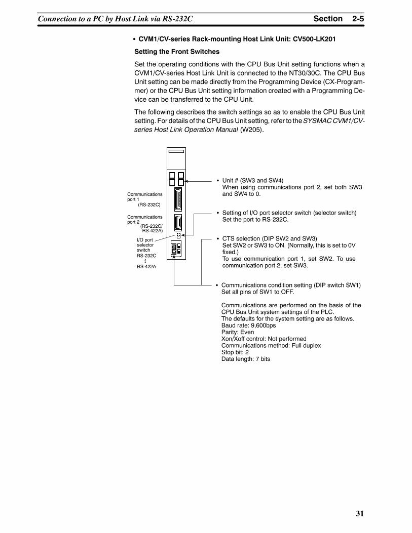
S CVM1/CV-series Rack-mounting Host Link Unit: CV500-LK201
Setting the Front Switches
Set the operating conditions with the CPU Bus Unit setting functions when aCVM1/CV-series Host Link Unit is connected to the NT30/30C. The CPU BusUnit setting can be made directly from the Programming Device (CX-Program-mer) or the CPU Bus Unit setting information created with a Programming De-vice can be transferred to the CPU Unit.
The following describes the switch settings so as to enable the CPU Bus Unitsetting. For details of theCPUBusUnit setting, refer to theSYSMACCVM1/CV-series Host Link Operation Manual (W205).
S Communications condition setting (DIP switch SW1)Set all pins of SW1 to OFF.
Communications are performed on the basis of theCPU Bus Unit system settings of the PLC.The defaults for the system setting are as follows.Baud rate: 9,600bpsParity: EvenXon/Xoff control: Not performedCommunications method: Full duplexStop bit: 2Data length: 7 bits
S Unit # (SW3 and SW4)When using communications port 2, set both SW3and SW4 to 0.
S Setting of I/O port selector switch (selector switch)Set the port to RS-232C.
S CTS selection (DIP SW2 and SW3)Set SW2 or SW3 to ON. (Normally, this is set to 0Vfixed.)To use communication port 1, set SW2. To usecommunication port 2, set SW3.
Communicationsport 1
Communicationsport 2
I/O portselectorswitchRS-232C↔RS-422A
(RS-232C/RS-422A)
(RS-232C)

2-5SectionConnection to a PC by Host Link via RS-232C
32
Connecting the NT30/30C to a CS1-series Serial Communications Unit
S CS1-series Rack-mounting Model: CS1W-SCU21
Setting the Front Switches
Set theunit number of theSerialCommunicationsUnit using the rotary switchonthe front of the Unit. Set the number or symbol in the setting display window inthe following way using a flat-blade screwdriver.
Unit Number Setting
Set to a value between 0 and F that doesnot coincide with the unit number set foranother Unit.
DM Area Allocation Settings
From the Programming Device (i.e., a Programming Console or CX-Program-mer), write the settings directly to the CPU Unit’s DM Area allocation (SetupArea). After the settings have beenwritten, they will be enabledwhen the powersupply is reset, theUnit is restarted, the communicationsports are restarted, or aSTUP instruction is executed.
TheDMAreawords that areallocatedand thecontentsof thesettingsareshownin the following table.
m = DM 30000 + 100 × unit number
DM Area Allocation (Words) Setting Setting Contents
Port 1 Port 2
g g
m m + 10 8000 Serial communications mode: Host Link; stop bits: 2; par-ity: even; data length: 7 bits
m + 1 m + 11 0000 Baud rate: 9,600 bps
0007 Baud rate: 19,200 bps
m + 2 m + 12 0000 Send delay time: 0 ms
m + 3 m + 13 0000 No CTS control; Host Link unit number: 0
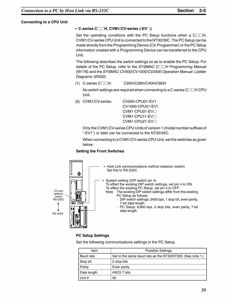
2-5SectionConnection to a PC by Host Link via RS-232C
33
Connecting to a CPU Unit
S C-series CjjH, CVM1/CV-series (-EVj)
Set the operating conditions with the PC Setup functions when a CjjH,CVM1/CV-seriesCPUUnit is connected to theNT30/30C. ThePCSetup canbemade directly from theProgrammingDevice (CX-Programmer) or the PCSetupinformation created with a Programming Device can be transferred to the CPUUnit.
The following describes the switch settings so as to enable the PC Setup. Fordetails of the PC Setup, refer to the SYSMAC CjjH Programming Manual(W176) and the SYSMAC CV500/CV1000/CV2000 Operation Manual: LadderDiagrams (W202)
(1) C-series CjjH: C20H/C28H/C40H/C60H
No switch settings are requiredwhen connecting to aC-series CjjHCPUUnit.
(2) CVM1/CV-series: CV500-CPU01-EV1CV1000-CPU01-EV1CVM1-CPU01-EVjCVM1-CPU11-EVjCVM1-CPU21-EVj
Only theCVM1/CV-seriesCPUUnits of version 1 (model number suffixes of“-EV1”) or later can be connected to the NT30/30C.
When connecting to aCVM1/CV-seriesCPUUnit, set the switches as givenbelow.
Setting the Front Switches
S System setting (DIP switch pin 4)To effect the existing DIP switch settings, set pin 4 to ON.To effect the existing PC Setup, set pin 4 to OFF.Note The existing DIP switch settings differ from the existing
PC Setup as follows.- DIP switch settings: 2400 bps, 1 stop bit, even parity,7-bit data length
- PC Setup: 9,600 bps, 2 stop bits, even parity, 7-bitdata length
I/O portselectorswitch
RS-232C
S Host Link communications method (selector switch)Set this to RS-232C.
RS-422A
PC Setup Settings
Set the following communications settings in the PC Setup.
Item Possible Settings
Baud rate Set to the same baud rate as the NT30/NT30C (See note 1.)
Stop bit 2 stop bits
Parity Even parity
Data length ASCII 7 bits
Unit # 00

2-5SectionConnection to a PC by Host Link via RS-232C
34
*1 Set the Host Link baud rate to 9,600 bps or 19,200 bps with the memoryswitch for the baud rate. For details, refer to Selecting the Host Link BaudRate (page 86).
S C-series C200HS, C200HX/HG/HE(-Z), CPM1, CPM2A, CPM2C, CQM1,CQM1H, SRM1
The method for connecting to the CPU Unit depends on the model of PC in theway shown in the following table.
PC Connection MethodC200HS, CQM1 S Connect to the CPU Unit’s RS-232C port.
C200HX/HG/HE(-Z) S Connect to the CPU Unit’s RS-232C port.
S Connect to one of the RS-232C ports (port A or B) on the CommunicationsBoard.
CQM1H S Connect to one of the RS-232C ports (port A or B) on the CommunicationsBoard.
S Connect via the CS1W-CN118 Connecting Cable using the peripheral port
S Connect to the RS-232C port (port 1) on the Serial Communications Board.
CPM1 S Connect via the CPM1-CIF01 RS-232C Adapter using the peripheral port.
CPM2A, SRM1 S Connect to the CPU Unit’s RS-232C port.
S Connect via the special RS-232C Adapter (CPM1-CIF01) using the peripheralport.
CPM2C S Connect to the CPU Unit’s RS-232C port or peripheral port using theCPM2C-CN111, CS1W-CN114, or CS1W-CN118 Connecting Cable. (TheCPM2C-CN111 splits the communications port on the CPU Unit into anRS-232C port and the peripheral port. The CPM1-CIF01 RS-232C Adapter isalso required to connect to the peripheral port.)
PC Setup Settings
When connecting to a C200HS, C200HX/HG/HE(-Z), CPM1, CPM2A, CPM2C,CQM1, or CQM1H CPU Unit, or to the SRM1, make the following communica-tions settings in the PC Setup.
Item Contents of Settings at Host
Communicationsmode
Host Link
Baud rate Set to the same baud rate as the NT30/NT30C (See note 1.)
Stop bit 2 stop bits
Parity Even
Data length ASCII 7 bits
Unit # 00
*1 Set the Host Link baud rate to 9,600 bps or 19,200 bps with the memoryswitch for the baud rate. For details, refer to Selecting the Host Link BaudRate (page 86).
Make the PC Setup settings directly from the Programming Device (CX-Pro-grammer). For details of PC Setup operations, refer to the manual for the PCused.
The following tables give the PC Setup words and the contents of settings fordifferent combinations of connected model and port.

2-5SectionConnection to a PC by Host Link via RS-232C
35
S Peripheral Port of CPM2A, CPM2C, CQM1H, SRM1
Word Setting Setting Contents
DM6650 0001 Host Link modeConditions set by the contents of DM.
DM66510303 Data length: 7 bits, 2 stop bits, even parity,
baud rate: 9,600 bpsDM6651
0304 Data length: 7 bits, 2 stop bits, even parity,baud rate: 19,200 bps
DM6653 0000 Unit No. 0
S RS-232C Port of C200HS, C200HX/HG/HE(-Z), CPM2A, CPM2C, CQM1,CQM1H (Except for CPU11), SRM1
Word Setting Setting Contents
DM6645 0001 Host Link mode, no CTS controlConditions set by the contents of DM.
DM66460303 Data length: 7 bits, 2 stop bits, even parity,
baud rate: 9,600 bpsDM6646
0304 Data length: 7 bits, 2 stop bits, even parity,baud rate: 19,200 bps
DM6648 0000 Unit No. 0
S Port A of Communications Board on C200HG/HX/HE(-Z), Port 1 of SerialCommunications Board on CQM1H
Word Setting Setting Contents
DM6555 0001 Host Link mode, no CTS controlConditions set by the contents of DM.
DM65560303 Data length: 7 bits, 2 stop bits, even parity,
baud rate: 9,600 bpsDM6556
0304 Data length: 7 bits, 2 stop bits, even parity,baud rate: 19,200 bps
DM6558 0000 Unit No. 0
S Port B of Communications Board on C200HG/HX/HE(-Z)
Word Setting Setting Contents
DM6550 0001 Host Link mode , no CTS controlConditions set by the contents of DM.
DM65510303 Data length: 7 bits, 2 stop bits, even parity,
baud rate: 9,600 bpsDM6551
0304 Data length: 7 bits, 2 stop bits, even parity,baud rate: 19,200 bps
DM6553 0000 Unit No. 0
S CPM1
Word Setting Setting Contents
DM6650 0001 Host Link modeConditions set by the contents of DM.
DM66510303 Data length: 7 bits, 2 stop bits, even parity,
baud rate: 9,600 bpsDM6651
0304 Data length: 7 bits, 2 stop bits, even parity,baud rate: 19,200 bps
DM6653 0000 Unit No. 0

2-5SectionConnection to a PC by Host Link via RS-232C
36
DIP Switch Setting for C200HX/HG/HE(-Z), CQM1, CQM1H
With the C200HX/HG/HE(-Z), CQM1, and CQM1H, in order that the PC Setupsettings (data memory) are enabled, set the DIP switch on the front panel in theway shown below.
C200HX/HG/HE(-Z) CQM1 CQM1H
RS-232C Port Communications Conditions SettingSet SW5 to OFF to enable the settings made in PC Setup.
When using the peripheral port on the CQM1H, set DIP switch pin 7 to ON also.
DIP Switch Setting for CPM2A
With the CPM2A, in order that the PC Setup settings (data memory) areenabled, set the DIP switch on the front panel in the way shown below.
Set the communicationssetting switch to OFF(down position).

2-5SectionConnection to a PC by Host Link via RS-232C
37
DIP Switch Setting for CPM2C
With the CPM2C, in order that the PC Setup settings (data memory) areenabled, set the DIP switches on the front panel in the way described below.
If (1) the PT is connected to the peripheral port or (2) the PT is connected to theRS-232C port and a device that requires communications settings other thanthe standard settings is connected to the peripheral port, set theDIP switches inthe way shown below.
Set SW1 to OFF.Set SW2 to ON.
Set the DIP switches according to the way the peripheralport and the RS-232C port are used.• If (1) the PT is connected to the peripheral port or (2) the PT is connected tothe RS-232C port and a device that requires communications settings otherthan the standard settings is connected to the peripheral port, set the DIPswitches in the way shown below.
• If the PT is connected to the RS-232C port and a Programming Console isconnected to the peripheral port, set the DIP switches in the way shownbelow.
Set SW1 to OFF.Set SW2 to OFF.
Switch Setting for the RS-232C Adapter
When using the CPM1-CIF01 RS-232C Adapter, set the mode setting switch inthe way shown below.
S Set the mode setting switch tohost (upper position).
CPM1CPM1-CIF01
S CS1-series CPU Unit: CS1H/G-CPUjj(-V1)
Connect to theCPUUnit’sRS-232Cport or theRS-232Cport of theCommunica-tionsBoard.Whenconnecting to theperipheral port, use theCS1W-CN118Con-necting Cable.
PC Setup Settings
When connecting to a CS1-series CPU Unit, make the PC Setup settings in thefollowing way. The settings are default settings for the PC Setup and so if thebaud rate is 9,600 bps, there is no need tomake any changes to the default set-tings.
Item Contents of Settings at Host
Baud rate Set to the same baud rate as the NT30/NT30C (See note 1.)
Stop bit 2 stop bits
Parity Even
Data length ASCII 7 bits
Unit # 00

2-5SectionConnection to a PC by Host Link via RS-232C
38
*1 Set the Host Link baud rate to 9,600 bps or 19,200 bps with the memoryswitch for the baud rate. For details, refer to Selecting the Host Link BaudRate (page 86).
Make the PC Setup settings by setting directly from a Programming Console orbymaking the settings on theCX-Programmer and then transferring them to theCPU Unit.
For details on thePCSetup, refer to theSYSMACCS1SeriesOperationManual(W339).
S RS-232C Port of CS1-series CPU Unit
Word Setting Setting Contents
IR/CIO 160 8000 Host Link mode, data length: 7 bits,2 stop bits, even parity
IR/CIO 1610000 Baud rate: 9,600 bps
IR/CIO 1610007 Baud rate: 19,200 bps
IR/CIO 163 0000 Unit No. 0
S Peripheral Port of CS1-series CPU Unit
Word Setting Setting Contents
IR/CIO 144 8000 Host Link mode, data length: 7 bits,2 stop bits, even parity
IR/CIO 1450000 Baud rate: 9,600 bps
IR/CIO 1450007 Baud rate: 19,200 bps
IR/CIO 147 0000 Unit No. 0
Setting the Front Switches
Set DIP switch 4 or 5 of the CPU Unit according to the port to which theNT30/NT30C is connected in the following way.
DIP Switch (Inside Battery Cover)
When the NT30/NT30C is connected to theperipheral port, set SW4 to ON (perform com-munications according to PC Setup settings).
When the NT30/NT30C is connected to theRS-232C port, set SW5 to OFF (perform com-munications according to PC Setup settings).
Peripheral Port
Mainly used for connectingProgramming Devices.(Connection of RS-232Cdevices also possible.)
RS-232C Port
Mainly used for connectingRS-232C devices.(Connection of CX-Pro-grammer also possible.)
S CS1-series Serial Communications Board: CS1W-SCB41/21
DM Area Allocation Settings
From the Programming Device (i.e., a Programming Console or CX-Program-mer), write the settings directly to the CPU Unit’s DM Area allocation (Setup

2-5SectionConnection to a PC by Host Link via RS-232C
39
Area). After the settings have beenwritten, they will be enabledwhen the powersupply is reset, theUnit is restarted, the communicationsports are restarted, or aSTUP instruction is executed.
TheDMAreawords that areallocatedand thecontentsof thesettingsareshownin the following table.
DM Area Allocation (Words) Setting Setting Contents
Port 1 Port 2
g g
DM32000 DM32010 8000 Host Link mode, 2 stop bits, data length: 7 bits, even parity
DM32001 DM32011 0000 Baud rate: 9,600 bps
0007 Baud rate: 19,200 bps
DM32002 DM32012 0000 Send delay time: 0 ms
DM32003 DM32013 0000 No CTS control; Host Link unit number: 0

Reference
2-6SectionConnection to a PC by Host Link via RS-422A
40
2-6 Connection to a PC by Host Link via RS-422AConnect theNT30/30C to anOMRONPCby using theRS-422AHost Linkmeth-od.
If thedistancebetween theNT30/30Cand thePC is greater than15m, thismeth-od should be used. The maximum distance over which a connection can bemade is 500 m.
When using the RS-422A method, the host computer and PC are usually con-nected in a 1 toN ratio (more than onePC), but in the special case of the connec-tion between the NT30/30C and PC, the ratio is 1 to 1.
In order to make a connection to the PC using the Host Link method (RS-422A),the host communications memory switch of the NT30/30C must be set to HostLink, and theportmemory switchmust beset toRS-422A.For details onmemoryswitch settings, see Selecting the Host Communication Method (page 85) andSelecting the Host Link Communication Port (page 87).
The terminating resistance setting on theNT30/NT30C (DIP switch 2 pin 8)mustalso be set to ON.
S By using the NT-AL001 RS-232C/RS-422A Link Adapter, it is possible to con-nect theRS-422A terminal block of theNT30/NT30C to the RS-232C connec-tor of the CPUUnit, Host Link Unit, or SRM1. In this case, set the communica-tions method for the NT30/NT30C to RS-422A and the communicationsmethod of the PC to RS-232C. For details of the connection method, refer tothe manual provided with the RS-232C/RS-422A Link Adapter.
S It is not possible to connect the NT30/NT30C to the PC using RS-485 (2-wire)Host Link communications.
2-6-1 Compatible PCsSome models and series of OMRON PCs have the Host Link function built in.
•WithCS1-series andCQM1HPCs,Host Link communications are possible byconnecting via a Serial Communications Board.
•With C200HX/HG/HE PCs, there are some CPU Units that support Host Linkcommunications when a Communications Board is mounted.
•With CPM2A and CPM2C PCs, connection to the NT30/NT30C can be madevia the CPM1-CIF11 RS-422A Adapter using RS-422A NT Link (1:1).
Check the model and series of the PC and the model of the Board or Unit beforemaking the connections.
TheUnits that canbe connected to theNT30/NT30C’sRS-422Aport as the host,and have RS-422A Host Link functionality are listed in the table below.

2-6SectionConnection to a PC by Host Link via RS-422A
41
PC Series CPU Units with theHost Link Function
Built In
CPU Units ConnectableUsing a Host Link Unit orCommunications Board
Host Link Unit orCommunications Board
ConnectablePC
CS1 series ---
CS1G-CPU42/43/44/45(-EV1)CS1H-CPU63/64/65/66/67(-EV1)
CS1W-SCB41 CS1GCS1H
--- C1000H-CPU01-EV1C2000H-CPU01-EV1 C120-LK202-V1 C1000H
C2000H
---
C200HS-CPU01/03/21/23/31/33-EC200HE-CPU11/32/42-(Z)EC200HG-CPU33/43/53/63-(Z)EC200HX-CPU34/44/54/64-(Z)E
C200H-LK202-V1
C200HSC200HEC200HE-ZC200HGC200HG-ZC200HXC200HX-Z
--- C200HE-CPU32/42-(Z)E C200HEC200HE-Z
--- C200HG-CPU33/43/53/63-(Z)E C200HW-COM03/06-V1 C200HG
C200HG-Z
--- C200HX-CPU34/44/54/64-(Z)E
C200HXC200HX-Z
C series--- C1000H-CPU01-EV1
C2000H-CPU01-EV1 C500-LK201-V1 C1000HC2000HC series
---C1000H-CPU01-EV1C1000HF-CPUA1-EV1C2000H-CPU01-EV1
C500-LK203 C1000H(F)C2000H
CPM1-10/20/30CDR-j + CPM1-CIF11
CPM1A-10/20/30/40CDj-j +CPM1-CIF11
CPM1
CPM2A-30/40/60CDjj-j +CPM1-CIF11 (whenconnected via periph-eral port)
--- ---
CPM2A
CPM2C-10/20jjjjjj-j (*1) CPM2C
--- CQM1H-CPU51/61-E CQM1H-SCB41 CQM1
CV500-CPU01-EV1 CV500-CPU01-EV1 CV500
CV series (*2) CV1000-CPU01-EV1 CV1000-CPU01-EV1 CV500-LK201 CV1000( )
CV2000-CPU01-EV1 CV2000-CPU01-EV1 CV2000
CVM1 series(*2)
CVM1-CPU01-EVjCVM1-CPU11-EVjCVM1-CPU21-EVj
CVM1-CPU01-EVjCVM1-CPU11-EVjCVM1-CPU21-EVj
CV500-LK201 CVM1
SRM1 SRM1-C02-V2 +CPM1-CIF11 --- --- SRM1
(*1) The CPM2C-CN111 or CS1W-CN114/118 Connecting Cable, theCPM1-CIF01 RS-232C Adapter, or the CPM1-CIF11 RS-422A Adapter isrequired.
(*2) Connection toCVM1/CV seriesPCCPUUnits that are not suffixed “-Vj” isnot possible. In the case of these CPU Units, make the connection to theNT30/30C by using a Host Link Unit.

2-6SectionConnection to a PC by Host Link via RS-422A
42
2-6-2 Parts Required for ConnectionThe RS-422A cable used for RS-422A communications is not supplied by OM-RON. Make this cable in accordance with the environment (PC used and trans-mission distance between the NT30/30C and PC).
Two connectors, two connector covers and one cable are required to make up aconnecting cable. One connector and one connector cover is supplied with thePC. However, a cable of the type recommended by OMRONmust be prepared.
For details onmaking thecable, refer toMaking theCableonpage279.The tablebelow lists the components supplied with each Unit and the recommendedcables.
Name Model Remarks
Connector XM2A-0901 9-pin, manufactured by OMRON- Delivered with C-series CQM1 andCVM1/CV-series CPU Unit.
- Delivered with the following Host Link- Delivered with the following Host LinkUnits:C200H-LK202-V1C500-LK203CV500-LK201
DE-9P 9-pin, manufactured by JAE- Delivered with the following Host LinkUnits:C200H-LK202-V1C500-LK201-V1
Connectorcover
XM2S-0911 9-pin, manufactured by OMRON- Delivered with C-series CQM1 andCVM1/CV-series CPU Unit.
- Delivered with the following Host Link- Delivered with the following Host LinkUnits:C200H-LK202-V1C500-LK203CV500-LK201
DE-CI-J6 9-pin, manufactured by JAE- Delivered with the following Host LinkUnits:C200H-LK202-V1C500-LK201-V1
Cable TKVVBS4P-03 Manufactured by Tachii Electric Wire
2-6-3 Method for ConnectionFor RS-422A communication, an RS-422A cable is used as the transmissionchannel connecting the NT30/30C and PC.
As shown in the figure below, the RS-422A cable is connected directly to theNT30/30C.
NT30/30C Host Link Unit/CPU Unit
RS-422A terminalblock
RS-422A connector cable (max. cable length: 500 m)
9-pin connector
SYSMAC CS1-series PC,C-series PC,CVM1/CV-series PC

Correct use
Caution
2-6SectionConnection to a PC by Host Link via RS-422A
43
S Ground the FG terminal of the PC to 100 Ω or less. For details, refer to themanual for the PC.
S SwitchOFF theNT30/30Cpower supplybefore connectingor disconnectingaconnector.
S After connecting the connector cable, be sure to secure the connector withscrews.
2-6-4 Connector Specifications and Wiring for Each Unit
The combination of pin numbers to which the connecting wires are connecteddiffers according to the connector specifications for eachUnit. Check the conne-ctor specifications of the Unit to be connected and make the wiring connectionsby referring to the relevant connection combination among those indicated be-low.
For details on making the cable, see Making the Cable (page 279).
NT30/30C RS-422A Terminal Block Specifications
• Connected terminal block:RS-422A terminal block (M3.5 screws)
• Electrical characteristics: Conform to EIA RS-422A
• Signal direction: Signal input and output is relative to theNT30/30C.
SDA SDB RDA RDB
Signal Name AbbreviationSignal Direction
Signal Name AbbreviationInput Output
Send data A SDA (SD--) f
Send data B SDB (SD+) f
Receive data A RDA (RD--) f
Receive data B RDB (RD+) f
Terminal Screws and Crimp Terminals on the NT30/NT30C’s RS-422A Ter-minal Block
The terminal screws have M3.5 specifications. Use M3.5-compatible crimp ter-minals for wiring. Tighten terminal screws to a torque not exceeding 0.8 N⋅m.
Be sure to use crimp terminals for wiring.
Examples of Compatible Crimp Terminals
Fork type Round type
7 mm or less 7 mm or less
Maker Model(fork type)
Applicable Wire(stranded wire)
Japan Solderless Terminal MFG 1.25-N3A SWG22 to AWG18Molex Y1.25-3.5L
SWG22 to AWG18(0.3 to 0.75 mm2)

1 6
95
1 6
95
2-6SectionConnection to a PC by Host Link via RS-422A
44
S Connecting the NT30/30C to a C-series Host Link Unit
C-series Host Link Connector Specifications
- Applicable Host Link Units: C200H-LK202-V1C500-LK202-V1C120-LK202-V1
- Electrical characteristics: Conform to EIA RS-422A
- Signal direction: Signal input and output is relative to the Host Link Unit.
Connector Signal Name AbbreviationSignal DirectionConnector
Pin No. Signal Name AbbreviationInput Output
1 Receive data B RDB f
3 Signal ground SG -- --
5 Send data B SDB f
6 Receive data A RDA f
7 Frame ground FG -- --
9 Send data A SDA f
Wiring Connections
Abbrevi-ation
SDASDBRDARDB
RS-422Aterminalblock
ShieldNT30/30C
PC (Host Link Unit)
RS-422Ainterface
Pinnumber
Abbrevi-ation
35679
RDBSGSDBRDAFGSDAFG
RS-422A cable
1
Connectorcover
S Connecting the NT30/30C to a C-series Host Link Unit (insulated)
C-series Host Link Connector Specifications
- Applicable Host Link Units: C500-LK203 (insulated)
- Electrical characteristics: Conform to EIA RS-422A
- Signal direction: Signal input and output is relative to the Host Link Unit.
Connector Signal Name AbbreviationSignal DirectionConnector
Pin No. Signal Name AbbreviationInput Output
Connectorcover Frame ground FG -- --
1 Receive data B RDB f
5 Send data B SDB f
6 Receive data A RDA f
7 Frame ground FG -- --
9 Send data A SDA f

1 6
95
2-6SectionConnection to a PC by Host Link via RS-422A
45
Wiring Connections
Connect the shield for the cable to pin No. 7 of the connector at the Host Link Unit side only.
Abbrevi-ation
SDASDBRDARDB
RS-422Aterminalblock
ShieldNT30/30C
PC (Host Link Unit)
RS-422Ainterface
Pinnumber
Abbrevi-ation
5679
RDB
SDBRDAFGSDAFG
RS-422A cable
1
Connector cover
S Connecting the NT30/30C to a CVM1/CV-series Host Link Unit
CVM1/CV-series Host Link Unit Connector Specifications
- Applicable Host Link Units: CV500-LK201 (communication port 2)
- Electrical characteristics: Conform to EIA RS-422A
- Signal direction: Signal input and output is relative to the Host Link Unit.
Connector Signal Name AbbreviationSignal DirectionConnector
Pin No. Signal Name AbbreviationInput Output
Connectorcover Frame ground FG -- --
1 Send data A SDA (SD--) f
2 Send data B SDB (SD+) f
6 Receive data A RDA (RD--) f
8 Receive data B RDB (RD+) f
Wiring Connections
Abbrevi-ation
SDASDBRDARDB
RS-422Aterminalblock
ShieldNT30/30C
PC (Host Link Unit)
RS-422Ainterface
Pinnumber
Abbrevi-ation
24568
SDASDB
RDARDBFG
RS-422A cable
1
Connector cover

1 6
95
2-6SectionConnection to a PC by Host Link via RS-422A
46
S Connecting the NT30/30C to a CVM1/CV-series CPU Unit
CVM1/CV-series CPU Unit Connector Specifications
- Applicable Host Link Units: CV500-CPU01-EV1CV1000-CPU01-EV1CV2000-CPU01-EV1CVM1-CPU01-EVVCVM1-CPU11-EVVCVM1-CPU21-EVV
Only the CVM1/CV-series CPU Units of version 1 (suffix of “-EV1”) or latercan be connected to the NT30/30C.
- Electrical characteristics: Conform to EIA RS-422A
- Signal direction: Signal input and output is relative to the PC.
Connector Signal Name AbbreviationSignal DirectionConnector
Pin No. Signal Name AbbreviationInput Output
Connectorcover Frame ground FG -- --
1 Send data A SDA (SD--) f
2 Send data B SDB (SD+) f
4 Request to send RS f
5 Clear to send CS f
6 Receive data A RDA (RD--) f
8 Receive data B RDB (RD+) f
Wiring Connections
Short pin No. 4 (RS) with pin No. 5 (CS) at the CPU Unit side.
Abbrevi-ation
SDASDBRDARDB
RS-422Aterminalblock
ShieldNT30/30C
PC (Host Link Unit)
RS-422Ainterface
Pinnumber
Abbrevi-ation
24568
SDASDBRSCSRDARDBFG
RS-422A cable
1
Connector cover

1 6
95
Reference
Caution
2-6SectionConnection to a PC by Host Link via RS-422A
47
S Connecting the NT30/30C to a Communications Board on a C200HX/HG/HE(-Z) or to a Serial Commu-nications Board on a CS1-series PC or CQM1H
Board RS-422A Connector Specifications
- Applicable Boards: C200HW-COM03-V1C200HW-COM06-V1CS1W-SCB41CQM1H-SCB41
- Electrical characteristics: Conform to EIA RS-422A
- Signal direction: Signal input and output is relative to the PC.
Connector Signal Name AbbreviationSignal DirectionConnector
Pin No. Signal Name AbbreviationInput Output
Connectorcover Frame ground FG -- --
1 Send data A SDA (SD--) f
2 Send data B SDB (SD+) f
6 Receive data A RDA (RD--) f
8 Receive data B RDB (RD+) f
Wiring Connections
Abbrevi-ation
SDASDBRDARDB
RS-422Aterminalblock
ShieldNT30/30C
PC (Host Link Unit)
RS-422Ainterface
Pinnumber
Abbrevi-ation
24568
Connector cover
SDASDBRSCSRDARDBFG
RS-422A cable
1
It is not possible to connect the NT30/NT30C to the PC using RS-485 (2-wire)Host Link communications.
S Connecting the NT30/30C to a CPM1, CPM2A, or CPM2C PC, or an SRM1
RS-422A Adapter Terminal Block Specifications
- Applicable RS-422A Adapter: CPM1-CIF11
- Electrical characteristics: Conform to EIA RS-422A
Wiring ConnectionsNT30/NT30C RS--422A Adapter
RS-422Aterminalblock
Abbreviation
RS-422A cable
RS-422Aterminalblock
Abbreviation
SDASDBRDARDB
SDASDBRDARDB
Terminal Screws and Crimp Terminals on the RS-422A Adapter’s RS-422ATerminal Block
The standard for terminal screws is M3. Use M3-compatible crimp terminals forwiring. Tighten terminal screws to a torque not exceeding 0.5 N⋅m.
Be sure to use crimp terminals for wiring.

Correct use
2-6SectionConnection to a PC by Host Link via RS-422A
48
2-6-5 PC Switch Settings
When the NT30/30C and PC are connected to each other, set the conditions atthe PC Host Link Unit or the CPU Unit as given in the table below.
The following is a general description of switch settings.
Refer to the manual for respective Units for details of the switch settings.
Item Switch Setting
I/O port RS-422A
Baud rate Set the same baud rate as the NT30/30C. (*1)
Transfer code ASCII 7 data bits, 2 stop bits
Parity Even
1-to-1/1-to-N 1-to-N (*2)
Command level Level 1, 2, 3
Unit # 00
*1 Set the Host Link baud rate to 9,600 bps or 19,200 bps with the memoryswitch for the baud rate. For details, refer to Selecting the Host Link BaudRate (page 86).
*2 The1-to-NsettingenablesBCC(BlockCheckCharacter). It is not possible toconnect more than one NT30/30C in a single Host Link.
When using the CVM1/CV series, always set CPU Unit execution processing(execution control 2) in the PC Setup to synchronous processing.
Connecting to a Host Link Unit
Two models of Host Link Units are available: Rack-mounting Unit and a CPU-mountingUnit. Theswitch settingsdiffer according to themodel ofHost LinkUnit.Set the switches according to the model of the Unit.
S C200H Rack-mounting Host Link Unit: C200H-LK202-V1
Setting the Front Switches
Set each switchwith a flat-blade screwdriver so that the values or symbols in thesetting value window agree with the switch settings indicated in the tableabove.
S Unit # (SW1, SW2)Set these switches to 0.
S Command level, parity, and transfer code (SW4)Set this switch to 2.
S Baud rate (SW3)Set this switch to 5 to select 9,600 bps.Set this switch to 6 to select 19,200 bps.
5 2

2-6SectionConnection to a PC by Host Link via RS-422A
49
C200H-LK202-V1
This Unit has an RS-422A connector.
S Terminator setting (selector switch)Set this switch to ON.Note: Set the link adapter to ON also.
S 1-to-1/1-to-N protocol selection (selector switch)Set this switch to 1-to-N (OFF)
CTSselectorswitchExternal(ON)
Unavailable(OFF)
1--to--1protocol(ON)
1--to--Nprotocol(OFF)
S C500/C1000H Rack-mounting Host Link Units: C500-LK201-V1 andC500-LK203
Setting the Front Switches
- C500-LK201-V1
Set the control mode to the Host Link mode. (page NO TAG)
Setting the Rear Switches
- C500-LK201-V1
S I/O port selection (selector switch)- If connecting to an RS-232C connector, set this to RS-232C.- If connecting to an RS-422A connector, set this to RS-422A.
CTS0VExternal
S Unit # (DIP switch SW1)Set pins 1 to 5 to OFF (0).
S Synchronization (selector switch)Set this to internal synchronization.
S Baud rate (DIP switch SW2 pins 1 to 4)Set these pins to 1010 to select 9,600 bps.Set these pins to 0010 to select 19,200 bps.
(0: OFF, 1: ON)
S 1-to-1/1-to-N selection (DIP switch SW2 pin 6)Set pin 6 to OFF (0) (1-to-N).
S Command level (DIP switch SW2 pins 7 and 8)Set these pins to ON (1).(Levels 1, 2, and 3 are enabled.)
S CTS selection (selector switch)Set this always to 0V (ON).
I/O portRS-422ARS-232C
SynchronizationInternalExternal
Terminationresistance
OFFON
S Terminator setting (selector switch)When using an RS-422A cable, set this to ON.Note: Set the Link Adapter to ON also.

2-6SectionConnection to a PC by Host Link via RS-422A
50
Setting the Rear Switches
- C500-LK203
CTS0VExternal
S I/O port selection (selector switch)- If connecting to an RS-232C connector, set this to RS-232C.- If connecting to an RS-422A connector, set this to RS-422A.
S Machine No., parity, transfer code settings(DIP switch SW1 pins 1 to 7)Set pins 1 to 7 to OFF (0).
S Synchronization (selector switch)Set this to Internal.
S Baud rate (DIP switch SW2 pins 1 to 4)Set these pins to 1010 to select 9,600 bps.Set these pins to 0010 to select 19,200 bps.
(0: OFF, 1: ON)
S 1-to-1/1-to-N selection (DIP switch SW2 pin 6)Set pin 6 to OFF (0) (1-to-N).
S Command level (DIP switch SW2 pins 7 and 8)Set these pins to ON (1).(Levels 1, 2, and 3 are enabled.)
5V supplyONOFF
SynchronizationInternalExternal
Terminationresistance
OFFON
I/O portRS-422ARS-232C
S Terminator setting (selector switch)When using an RS-422A cable, set this to ON.Note: Set the Link Adapter to ON also.
S CTS selection (selector switch)Set this always to 0 V (ON).

2-6SectionConnection to a PC by Host Link via RS-422A
51
S CPU-mounting Host Link Units: C120-LK201-V1 and C120-LK202-V1
Setting the Rear Switches
S Terminator setting (C120-LK202-V1)(DIP switch SW3 pins 1 to 6)When using an RS-422A cable, set pins 1, 3, and 5 to ON (1), andset pins 2, 4, and 6 to OFF (0).(Set this for termination.)Note: Set the Link Adapter for termination too.
S Unit #, parity, and transfer code (DIP switch SW1 pins1 to 5)Set pins 1 to 5 to OFF (0).* Parity is fixed at even parity. Transfer code is fixedat ASCII 7 data bits and 2 stop bits.
S Baud rate (DIP switch SW2 pins 1 to 4)Set these pins to 1010 to select 9,600 bps.Set these pins to 0010 to select 19,200 bps.
(0: OFF, 1: ON)
S 1-to-1/1-to-N selection (DIP switch SW2 pin 6)Set pin 6 to OFF (0) (1-to-N).
S Command level (C120-LK201-V1) (DIP switch SW2 pins 7 and 8)Set these pins to ON (1).(Levels 1, 2, and 3 are enabled.)
S CTS selection (C120-LK201-V1)(DIP switch SW3 pins 1 and 2)Set pin 1 to ON (1) and pin 2 to OFF (0).(Set this always to 0 V.)
S Synchronization (C120-LK201-V1)(DIP switch SW3 pins 3 to 6)Set pins 3 and 5 to ON (1) and pins 4 and 6 to OFF (0).Set this to Internal synchronization.
S CVM1/CV-series Rack-mounting Host Link Unit: CV500-LK201
Setting the Front Switches
Set the operating conditions with the CPU Bus Unit setting functions when anNT30/30Cand aCVM1/CV-seriesHost LinkUnit is connected to theNT30/30C.The CPU Bus Unit setting can be made directly from the Programming Device(CX-Programmer) or the CPU Bus Unit setting information created with a Pro-gramming Device can be transferred to the CPU Unit.

2-6SectionConnection to a PC by Host Link via RS-422A
52
The following describes the switch settings so as to enable the CPU Bus Unitsetting. For details of theCPUBusUnit setting, refer to theSYSMACCVM1/CV-series Host Link Operation Manual (W205).
S Communications condition setting (DIP switch pin 1)Set pin 1 to OFF.
Communications are performed on the basis of theCPU Bus Unit system settings of the PLC.The defaults for the system setting are as follows.Baud rate: 9,600 bpsParity: EvenXon/Xoff control: Not performedCommunications method: Full duplexStop bit: 2Data length: 7 bits
S Unit # (SW3 and SW4)Set these switches to 0.(when using communications port 2)
S CTS selection (DIP switch pins 2 and 3)Set pins 2 or 3 to ON. (Set this always to 0 V fixed.)To use communication port 1, set pin 2. To use commu-nication port 2, set pin 3.
Communicationsport 1
Communicationsport 2
I/O portselectorswitchRS-232C↔
RS-422A
(RS-232C/RS-422A)
(RS-232C)
S Terminator setting (selector switch)When using an RS-422A cable, set this to ON.
S Setting of I/O port selector switch (selector switch)Set this to RS-422A.
TerminatorON↔
OFF
Connecting to a CPU Unit
Set the communication conditions with the PC Setup functions when aCVM1/CV-series Host Link Unit is connected to the NT30/30C. The PC Setupcan bemadedirectly from theProgrammingDevice (CX-Programmer) or thePCSetup information created with a Programming Device can be transferred to theCPU Unit.
The following describes the switch settings so as to enable the PC Setup. Fordetails of the PC Setup, refer to the SYSMAC C20H/C28H/C40H/C60H Pro-grammingManual (W176) and theSYSMACC-series andCVM1PCsSYSMACSupport Software Operation Manual: CVM1 PCs (W249).
CVM1/CV-series: CV500-CPU01-EV1CV1000-CPU01-EV1CVM1-CPU01-EVjCVM1-CPU11-EVjCVM1-CPU21-EVj
Only theCVM1/CV-seriesCPUUnits or version1 (suffix of “-EV1”) or later canbeconnected to the NT30/30C.

Reference
2-6SectionConnection to a PC by Host Link via RS-422A
53
Setting the Front Switches
S Host Link communications method (selector switch)- If connecting to an RS-232C connector, set this to RS-232C.- If connecting to an RS-422A connector, set this to RS-422A.
S Host Link default value setting (DIP switch pin 4)To effect the existing DIP switch settings, set pin 4 to ON.To effect the existing PC Setup, set pin 4 to OFF.Note: The existing DIP switch settings differ from the existing
PC Setup as follows.- DIP switch settings: 2400 bps, 1 stop bit, even parity,7-bit data length
- PC Setup: 9,600 bps, 2 stop bits, even parity, 7-bitdata length
I/O portselectorswitchRS-232C
RS-422AS Terminator setting (DIP switch pin 6)When using an RS-422A cable, set pin 6 to ON.(Set this for termination.)Note: Set the Link Adapter to ON also.
PC Setup Settings
Set the following communications settings in the PC Setup.
Item Possible Settings
Baud rate Set to the same baud rate as the NT30/NT30C (See note 1.)
Stop bit 2 stop bits
Parity Even
Data length ASCII 7 bits
Unit # 00
*1 Set the Host Link baud rate to 9,600 bps or 19,200 bps with the memoryswitch for the baud rate. For details, refer to Selecting the Host Link BaudRate (page 86).
S C-series C200HX/HG/HE(-Z), CPM1, CPM2A, CPM2C, or CQM1H CPUUnit, or SRM1
The method for connecting to the CPU Unit depends on the model of PC in theway shown in the following table.
PC Connection MethodC200HX/HG/HE(-Z) S Connect to the RS-422A port (port A) on the Communications Board.
CQM1H S Connect to the RS-422A port (port 2) on the Serial Communications Board.
CPM1 S Connect via the CPM1-CIF11 RS-422A Adapter using the peripheral port.
CPM2A, SRM1 S Connect via the CPM1-CIF11 RS-422A Adapter using the peripheral port.
CPM2C S Connect to the peripheral port using the CPM2C-CN111 or CS1W-CN114 Con-necting Cable and the CPM1-CIF11 RS-422A Adapter. (The CPM2C-CN111splits the communications port on the CPU Unit into an RS-232C port and theperipheral port. The CPM1-CIF01 RS-232C Adapter is also required to connectto the peripheral port.)
S There are no Communications Boards for C200HX/HG/HE(-Z) PCs for whichport B is the RS-422A port.
S There are no Serial Communications Boards for CQM1HPCs for which port 1is the RS-422A port.

2-6SectionConnection to a PC by Host Link via RS-422A
54
PC Setup Settings
When connecting to a C200HX/HG/HE(-Z), CPM1, CPM2A, CPM2C, orCQM1HCPUUnit, or to theSRM1,make the following communications settingsin the PC Setup.
Item Contents of Settings at Host
I/O port RS-422A
Communicationsmode
Host Link
Baud rate Set to the same baud rate as the NT30/NT30C (See note 1.)
Stop bit 2 stop bits
Parity Even
Data length ASCII 7 bits
Unit # 00
*1 Set the Host Link baud rate to 9,600 bps or 19,200 bps with the memoryswitch for the baud rate. For details, refer to Selecting the Host Link BaudRate (page 86).
Make the PC Setup settings directly from the Programming Device (CX-Pro-grammer). For details of PC Setup operations, refer to the manual for the PCused.
The following tables give the PC Setup word numbers and the contents of set-tings for different combinations of connected model and port.
S Port A of Communications Board on C200HG/HX/HE(-Z)
Word Setting Setting Contents
DM6555 0001 Host Link mode, no CTS controlConditions set by the contents of DM.
DM65560303 Data length: 7 bits, 2 stop bits, even parity,
baud rate: 9,600 bpsDM6556
0304 Data length: 7 bits, 2 stop bits, even parity,baud rate: 19,200 bps
DM6558 0000 Unit No. 00
S CPM1, CPM2A, CPM2C, or SRM1
Word Setting Setting Contents
DM6650 0001 Host Link mode, no CTS controlConditions set by the contents of DM.
DM66510303 Data length: 7 bits, 2 stop bits, even parity,
baud rate: 9,600 bpsDM6651
0304 Data length: 7 bits, 2 stop bits, even parity,baud rate: 19,200 bps
DM6653 0000 Unit No. 00
S CQM1H
Word Setting Setting Contents
DM6550 0001 Host Link mode, no CTS controlConditions set by the contents of DM.
DM65510303 Data length: 7 bits, 2 stop bits, even parity,
baud rate: 9,600 bpsDM6551
0304 Data length: 7 bits, 2 stop bits, even parity,baud rate: 19,200 bps
DM6553 0000 Unit No. 00
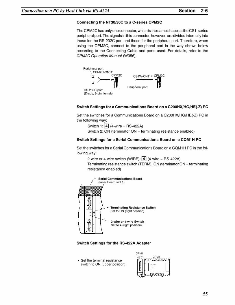
2-6SectionConnection to a PC by Host Link via RS-422A
55
Connecting the NT30/30C to a C-series CPM2C
TheCPM2Chasonlyoneconnector,which is thesameshapeas theCS1-seriesperipheral port. Thesignals in this connector, however, aredivided internally intothose for the RS-232C port and those for the peripheral port. Therefore, whenusing the CPM2C, connect to the peripheral port in the way shown belowaccording to the Connecting Cable and ports used. For details, refer to theCPM2C Operation Manual (W356).
Peripheral portCPM2C-CN111
CPM2C
RS-232C port(D-sub, 9-pin, female)
CS1W-CN114
Peripheral port
CPM2C
Switch Settings for a Communications Board on a C200HX/HG/HE(-Z) PC
Set the switches for a Communications Board on a C200HX/HG/HE(-Z) PC inthe following way:
Switch 1: 44 (4-wire = RS-422A)Switch 2: ON (terminator ON = terminating resistance enabled)
Switch Settings for a Serial Communications Board on a CQM1H PC
Set the switches for a Serial Communications Board on a CQM1HPC in the fol-lowing way:
2-wire or 4-wire switch (WIRE): 44 (4-wire = RS-422A)Terminating resistance switch (TERM): ON (terminator ON = terminatingresistance enabled)
Serial Communications Board(Inner Board slot 1)
Terminating Resistance SwitchSet to ON (right position).
2-wire or 4-wire SwitchSet to 4 (right position).
Switch Settings for the RS-422A Adapter
S Set the terminal resistanceswitch to ON (upper position).
CPM1CPM1-CIF11

2-7SectionConnection to a PC by the NT Link
56
S CS1-series Serial Communications Board: CS1W-SCB41 (Port 2)
DM Area Allocation Settings
From the Programming Device (i.e., a Programming Console or CX-Program-mer), write the settings directly to the CPU Unit’s DM Area allocation (SetupArea). After the settings have beenwritten, they will be enabledwhen the powersupply is reset, theUnit is restarted, the communicationsports are restarted, or aSTUP instruction is executed.
TheDMAreawords that areallocatedand thecontentsof thesettingsareshownin the following table.
DM Area Allocation(words)
Setting Setting Contents
Port 232010 8000 Host Link mode, 2 stop bits, data length: 7
bits, even parity
32011 0000 Baud rate: 9,600 bps
0007 Baud rate: 19,200 bps
32012 0000 Send delay time: 0 ms
32013 0000 No CTS control; Host Link unit number: 0
2-7 Connection to a PC by the NT LinkConnect the NT30/30C to an OMRON PC by the NT Link method.
To connect an NT30/30C to a PC by the NT Link method, the communicationsmethod memory switch of the NT30/30C must be set to NT Link. For details onthe communicationmethodmemory switch setting, refer toSelecting of theHostCommunication Method (page 85).
2-7-1 Compatible PCsSome models and series of OMRON PCs have the NT Link function built in.There are also C200HX/HG/HE(-Z) andCQM1HCPUUnits that can be used forNT Link communicationswhen aBoard ismounted. Check themodel and seriesof the PC, and the model of the CPU Unit before making the connections.
The PCs that can be connected by NT Link are listed in the table below.

2-7SectionConnection to a PC by the NT Link
57
PC series CPU Units with the NTLink Function Built In
CPU Units Connect-able Using a Commu-
nications Board
ConnectablePC
CPM1-10CDR-j (*1)CPM1-20CDR-j (*1)CPM1-30CDR-j (*1)CPM1-30CDR-j-V1CPM1A-10CDj-j(*1)CPM1A-20CDj-j(*1)CPM1A-30CDj-j(*1)CPM1A-40CDj-j(*1)
--- CPM1
CPM2A-30CDjj-jCPM2A-40CDjj-jCPM2A-60CDjj-j
--- CPM2A
CPM2C-10jjjjjj-j (*2)CPM2C-20jjjjjj-j (*2)
--- CPM2C
CQM1-CPU41-EV1CQM1-CPU42-EV1CQM1-CPU43-EV1CQM1-CPU44-EV1
--- CQM1
CQM1H-CPU21CQM1H-CPU51CQM1H-CPU61
CQM1H-CPU51 (*3)CQM1H-CPU61 (*3) CQM1H
C series C200HS-CPU21-EC200HS-CPU23-EC200HS-CPU31-EC200HS-CPU33-E
--- C200HS
C200HE-CPU42-(Z)E
C200HE-CPU32-(Z)E(*4)C200HE-CPU42-(Z)E(*4)
C200HE(-Z)
C200HG-CPU43-(Z)EC200HG-CPU63-(Z)E
C200HG-CPU33-(Z)E(*4)C200HG-CPU43-(Z)E(*4)C200HG-CPU53-(Z)E(*4)C200HG-CPU63-(Z)E(*4)
C200HG(-Z)
C200HX-CPU44-(Z)EC200HX-CPU64-(Z)EC200HX-CPU65-(Z)EC200HX-CPU85-(Z)E
C200HX-CPU34-(Z)E(*4)C200HX-CPU44-(Z)E(*4)C200HX-CPU54-(Z)E(*4)C200HX-CPU64-(Z)E(*4)C200HX-CPU65-(Z)E(*4)C200HX-CPU85-(Z)E(*4)
C200HX(-Z)
CV500-CPU01-EV1 --- CV500
CV series (*5) CV1000-CPU01-EV1 --- CV1000( )
CV2000-CPU01-EV1 --- CV2000

Correct use
2-7SectionConnection to a PC by the NT Link
58
PC series ConnectablePC
CPU Units Connect-able Using a Commu-
nications Board
CPU Units with the NTLink Function Built In
CVM1 series(*5)
CVM1-CPU01-EVjCVM1-CPU11-EVjCVM1-CPU21-EVj
--- CVM1
CompoBus/SMaster ControlUnit
SRM1-C02-V2 --- SRM1
*1 The CPM1-CIF01 Adapter is required.
*2 The CPM2C-CN111 or CS1W-CN114/118 Connecting Cable, theCPM1-CIF01 RS-232C Adapter, or the CPM1-CIF11 RS-422A Adapter isrequired.
*3 The CQM1H-SCB41 Serial Communications Board is required.
*4 One of the C200HW-COM02/COM03/COM04/COM05/COM06(-V1) Com-munications Boards is required. (The RS-422A Connecting Cable can beconnected to the C200HW-COM03/COM06-V1.)
*5 CVM1 and CV-series CPUUnits without “-Vj” at the end of the model num-ber cannot be connected.
2-7-2 Connecting the NT30/30CRefer to the illustrations below to select the appropriate cable for the Unit con-nectors and connect the NT30/30C to the PC.
A Host Link connector cable can also be used. Tomake a connector cable, referto the appendix Making the Cable for Connection to the PC (page 271).
S After connecting a communication cable, always secure it with the screws.Otherwise the cable may disconnect, causing operation to fail.
S The cable’s tensile load is 30 N. Do not subject it to loads greater than this.Otherwise a discontinuity may occur, causing operation to fail.
Use a connector cable with a 9-pin connector on both ends to connect theNT30/30C to a PC with a 9-pin connector.
CPU Unit
SYSMAC C-seriesPC,CVM1/CV-seriesPC
Host I/F connector(RS-232C 9-pin)
9-pin connector
RS-232C connectorcable
9-pin connector
NT30/30C
RDB 24 VDC
PRINTER
RS-232C
SW2 RE-SET
--CON-TRAST
SD
A
The following are recommended cables (manufactured by OMRON)
Connector Specification Model Cable Length
9 pin↔ 9 pinSJ46006-102 1 m
9-pin↔ 9-pinSJ46006-202 2 m
When a Connector Cable of 5 m or Longer Is Required
When a connector cable of 5 m or longer is required, please make the cable.However, note that the maximum transmission distance is 15 m.
To make a connector cable, refer to the appendixMaking the Cable for Connec-tion to the PC (page 271).

2-7SectionConnection to a PC by the NT Link
59
When Long-distance Communications are Required
Communications distances greater than RS-232C standards can be achievedusing RS-422A communications (RS-485 communications cannot be used).
2-7-3 PC Switch Settings (RS-232C at PC Side)The setting methods for different types of Units are given below.
S C-series C200HS, C200HX/HG/HE(-Z), CPM1, CPM2A, CPM2C, CQM1,CQM1H, SRM1
PC Setup
Write the settings directly from theProgrammingDevice (e.g.,CX-Programmer)to the PC Setup (data memory) according to the model of the host and the portused.
Host Word Setting Setting Con-tents
RS-232C port of C200HS,C200HX/HG/HE(-Z), CPM2A,CPM2C, CQM1, CQM1H, orSRM1
DM6645 4000 NT (1:1) Link isused.
Port A of C200HX/HG/HE(-Z)(See note 1.) or port 1 ofCQM1H (See note 2.)
DM6555
Port B (See note 1.) ofC200HX/HG/HE(-Z)
DM6550
CPM1 DM6550
Note 1. RS-232C port of Communications Board.
2. RS-232C port of Serial Communications Board.
For details of PC Setup operations, refer to the manual for the PC used.
Connecting the NT30/30C to a C-series CPM2C
TheCPM2Chasonlyoneconnector,which is thesameshapeas theCS1-seriesperipheral port. Thesignals in this connector, however, aredivided internally intothose for the RS-232C port and those for the peripheral port. Therefore, whenusing theCPM2C,make separate settings for theRS-232C port and the periph-eral port according to the conversion cables and ports used, in theway shown inthe following table. For details, refer to the CPM2C Operation Manual (W356).
Port Connected to the PT PC Setup
RS-232C port of the CS1W-CN111 (D-sub, 9-pin) Perform settings for the RS-232C port
Peripheral port of the CS1W-CN111 Perform settings for the peripheral port
Port of the CS1W-CN118 (D-sub, 9-pin) Perform settings for the RS-232C port
Port of the CS1W-CN114 (peripheral port) Perform settings for the peripheral port
Peripheral port
RS-232C port(D-sub, 9-pin, female)
CPM2C-CN111CPM2C CPM2CCS1W-CN118
RS-232C port(D-sub, 9-pin, female)
CS1W-CN114 CPM2C
Peripheral port

2-7SectionConnection to a PC by the NT Link
60
DIP Switch Setting for C200HX/HG/HE(-Z), CQM1, CQM1H
With the C200HX/HG/HE(-Z), CQM1, and CQM1H, in order that the PC Setupsettings (data memory) are enabled, set the DIP switch on the front panel in theway shown below.
C200HX/HG/HE(-Z) CQM1 CQM1H
RS-232C Port Communications Conditions SettingSet SW5 to OFF to enable the settings made in PC Setup.
DIP Switch Setting for CPM2A
With the CPM2A, in order that the PC Setup settings (data memory) areenabled, set the DIP switch on the front panel in the way shown below.
Set the communicationssetting switch to OFF(down position).
DIP Switch Setting for CPM2C
With the CPM2C, in order that the PC Setup settings (data memory) areenabled, set the DIP switches on the front panel in the way described below.
Set SW1 to OFF.Set SW2 to ON.
Set the DIP switch according to the way the peripheral portand the RS-232C port are used.• If (1) thePT is connected to theperipheral port or (2) thePT is connected to theRS-232C port and a device that requires communications settings other thanthe standard settings is connected to the peripheral port, set the DIP switchesin the way shown below.
• If the PT is connected to the RS-232C port and a Programming Console isconnected to theperipheral port, set theDIP switches in theway shownbelow.
Set SW1 to OFF.Set SW2 to OFF.

Correct use
2-7SectionConnection to a PC by the NT Link
61
Switch Setting for the RS-232C Adapter
When using the CPM1-CIF01 RS-232C Adapter, set the mode setting switch inthe way shown below.
S Set the mode setting switch toNT (down position).
CPM1
CPM1-CIF01
S CVM1/CV-series (-EVj)
When connecting to a CVM1/CV-series (-EVj) CPU Unit, set the switches asgiven below.
I/O port selection (selector switch)Set this to RS-232C.
NT Link settingSet SW3 to ON (right side).
DDDDDD
ON1
23
45
6
OFF↔ON
DIP switch setting (SW3)
When using the CVM1/CV series, always set CPU Unit execution processing(execution control 2) in the PC Setup to synchronous processing.
2-7-4 PC Switch Settings (RS-422A at PC Side)The setting methods for different types of Units are given below.
S CVM1/CV-series “-Vj” CPU Units
The settings required for the following CPU Units are described below.
CV500-CPU01-V1/CV1000-CPU01-V1/CV2000-CPU01-V1CVM1-CPU01-Vj/CVM1-CPU11-Vj/CVM1-CPU21-Vj

2-7SectionConnection to a PC by the NT Link
62
Setting the Front Switches
S Host Link communications method (selector switch)- Set to RS-422A.
S Communications method (DIP switch pin 3)Set pin 3 to ON (NT Link).
I/O portselectorswitchRS-232C
RS-422AS Terminator setting (DIP switch pin 6)Set pin 6 to ON (terminating resistance enabled).
PC Setup Settings
There are no particular settings required in the PC Setup for connecting to aCVM1/CV-series CPU Unit via NT Link (1:1).
S C-series C200HX/HG/HE(-Z) or CQM1H
PC Setup Settings
Write the settings directly from theProgrammingDevice (e.g.,CX-Programmer)to the PC Setup (data memory) according to the model of the host used.
Host Word Setting Setting Con-tents
Port A of C200HX/HG/HE(-Z)(See note 1.)
DM6555 4000 NT Link isused.
Port 2 of CQM1H(See note 2.)
DM6550 4000
sed
*1 RS-422A port of Communications Board.
*2 RS-422A port of Serial Communications Board.
For details of PC Setup operations, refer to the manual for the PC used.
Switch Settings for a Communications Board on a C200HX/HG/HE(-Z) PC
Set the switches for a Communications Board on a C200HX/HG/HE(-Z) PC inthe following way:
Switch 1: 44 (4-wire = RS-422A)Switch 2: ON (terminator ON = terminating resistance enabled)
Switch Settings for a Serial Communications Board on a CQM1H PC
Set the switches for a Serial Communications Board on a CQM1HPC in the fol-lowing way:
2-wire or 4-wire switch (WIRE): 44 (4-wire = RS-422A)Terminating resistance switch (TERM): ON (terminator ON = terminatingresistance enabled)

2-8SectionConnecting a Printer
63
Serial Communications Board(Inner Board slot 1)
Terminating Resistance SwitchSet to ON (right position).
2-wire or 4-wire SwitchSet to 4 (right position).
S RS-232C/RS-422A Link Adapter (NT-AL001)
Whenusing theNT30/30C ina1:1RS-422Aconnection,make the followingDIPswitch settings at the RS-232C/RS-422 Link Adapter (NT-AL001) used for relaypurposes.
1 2 3 4 5 6
ON
RS-422A transmission mode selection(DIP switch pins 5 and 6)Set pin 5 to OFF and pin 6 to ON.(This sets RS control to RS-232C.)
Setting for built-in terminal resistor(DIP switch pin 2)Set pin 2 to ON.(This sets the built-in terminal resistor).
2-wire/4-wire selection(DIP switch pins 3 and 4)Set both pin 3 and 4 to OFF.(This sets a 4-wire connection.).
2-8 Connecting a PrinterHard copies of screens can be printed (printing of screen images) onto a printerconnected to the NT30/30C.
In order tomake a hard copy at a printer connected to the NT30/30C, it is neces-sary either to create a screen print key as a touch switch on the screen to beprinted during screen creation, or to issue a print instruction from the PC. For de-tails, see 4-7 Touch Switches (page 154), and 5-7 NT30/30C Status Control(page 239).

Reference
2-9SectionConnection of Expanded I/O
64
2-8-1 How to ConnectConnect the printer to the NT30/30C with a Centronics cable. The length of thecable should not exceed 3 meters.
If the connection cable is connected or disconnected while the power of theprinter is on, the NT30/30Cmay malfunction. Make sure to turn OFF the powerof the printer before connecting or disconnecting the connection cable.
EPSON ESC/PColor Printer (24-pin),Monochrome Printer (24-pin)
24 VDC+
PRINTER RS-232C
SW2 RESET --CONTRAST
SDA SDB RDA RDB
S Recommended Connection Cable
The following connection cable is recommended.
NT-CNT121 connection cable (1.5 m, 20-pin to 36-pin)
S Recommended Printer
Use a printer that conforms to the control standard of the PC-PR201 made byNEC, or use a printer that conforms the following EPSON printer control stan-dard: ESC/P J83 (color or monochrome)
When using a monochrome printer with an NT30/30C, set the tone with theNT30/30C memory switches (see page 99).
2-9 Connection of Expanded I/OTo provide expanded I/O for the NT30/30C, the B7A Unit can be connected. Inorder to enable the B7A Unit to be connected, the optional B7A Interface Unit(NT-B7A16) must be installed on the NT30/30C.
This section explains how to use the B7A Interface Unit and how to connect theB7A Unit.
2-9-1 Connectable B7A Units
I/OClassification Wiring Type Transmission Delay
Time I/O Format + -- TerminalConfiguration Model
16 input points Screw terminal Standard (Typ. 19.2 ms) NPN input -- only B7A-T6A1
Alternate + and -- B7A-T6B1
PNP input Alternate + and -- B7A-T6C1
High speed (Typ. 3 ms) NPN input -- only B7A-T6A6
Alternate + and -- B7A-T6B6
PNP input Alternate + and -- B7A-T6C6
Module Standard (Typ. 19.2 ms) TTL input -- B7A-T6D2
High speed (Typ. 3 ms) -- B7A-T6D7
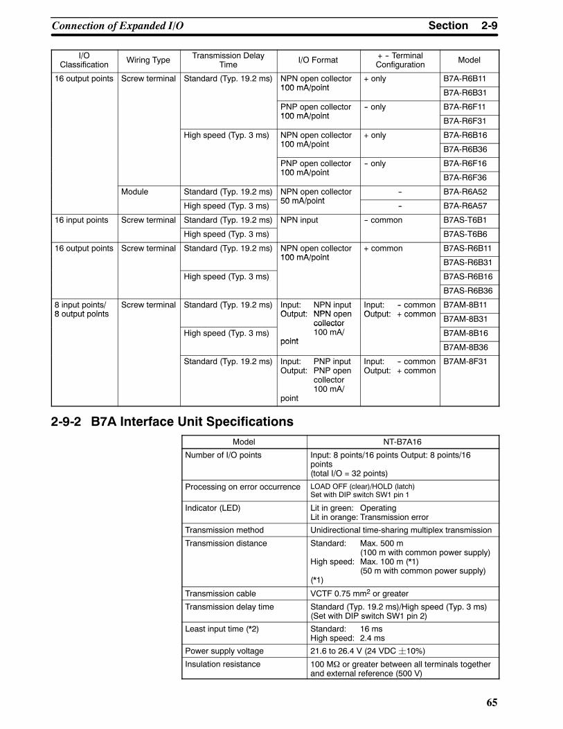
2-9SectionConnection of Expanded I/O
65
I/OClassification Model+ -- Terminal
ConfigurationI/O FormatTransmission DelayTimeWiring Type
16 output points Screw terminal Standard (Typ. 19.2 ms) NPN open collector100 mA/point
+ only B7A-R6B11100 mA/point
B7A-R6B31
PNP open collector100 mA/point
-- only B7A-R6F11100 mA/point
B7A-R6F31
High speed (Typ. 3 ms) NPN open collector100 mA/point
+ only B7A-R6B16100 mA/point
B7A-R6B36
PNP open collector100 mA/point
-- only B7A-R6F16100 mA/point
B7A-R6F36
Module Standard (Typ. 19.2 ms) NPN open collector50 mA/point
-- B7A-R6A52
High speed (Typ. 3 ms)50 mA/point
-- B7A-R6A57
16 input points Screw terminal Standard (Typ. 19.2 ms) NPN input -- common B7AS-T6B1
High speed (Typ. 3 ms) B7AS-T6B6
16 output points Screw terminal Standard (Typ. 19.2 ms) NPN open collector100 mA/point
+ common B7AS-R6B11100 mA/point
B7AS-R6B31
High speed (Typ. 3 ms) B7AS-R6B16
B7AS-R6B36
8 input points/8 output points
Screw terminal Standard (Typ. 19.2 ms) Input: NPN inputOutput: NPN open
Input: -- commonOutput: + common
B7AM-8B118 output points Output: NPN open
collectorOutput: + common B7AM-8B31
High speed (Typ. 3 ms)collector100 mA/
pointB7AM-8B16
pointB7AM-8B36
Standard (Typ. 19.2 ms) Input: PNP inputOutput: PNP open
collector100 mA/
point
Input: -- commonOutput: + common
B7AM-8F31
2-9-2 B7A Interface Unit SpecificationsModel NT-B7A16
Number of I/O points Input: 8 points/16 points Output: 8 points/16points(total I/O = 32 points)
Processing on error occurrence LOAD OFF (clear)/HOLD (latch)Set with DIP switch SW1 pin 1
Indicator (LED) Lit in green: OperatingLit in orange: Transmission error
Transmission method Unidirectional time-sharing multiplex transmission
Transmission distance Standard: Max. 500 m(100 m with common power supply)
High speed: Max. 100 m (*1)(50 m with common power supply)
(*1)
Transmission cable VCTF 0.75 mm2 or greater
Transmission delay time Standard (Typ. 19.2 ms)/High speed (Typ. 3 ms)(Set with DIP switch SW1 pin 2)
Least input time (*2) Standard: 16 msHigh speed: 2.4 ms
Power supply voltage 21.6 to 26.4 V (24 VDC¦10%)
Insulation resistance 100 MΩ or greater between all terminals togetherand external reference (500 V)
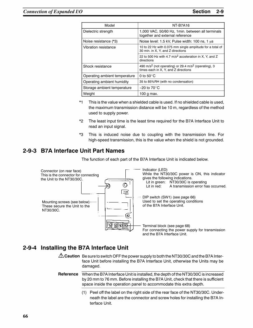
Caution
Reference
2-9SectionConnection of Expanded I/O
66
Model NT-B7A16
Dielectric strength 1,000 VAC, 50/60 Hz, 1min. between all terminalstogether and external reference
Noise resistance (*3) Noise level: 1.5 kV, Pulse width: 100 ns, 1 μs
Vibration resistance 10 to 22 Hz with 0.075 mm single amplitude for a total of30 min. in X, Y, and Z directions
22 to 500 Hz with 4.7 m/s2 acceleration in X, Y, and Zdirections
Shock resistance 490 m/s2 (not operating) or 29.4 m/s2 (operating), 3times each in X, Y, and Z directions
Operating ambient temperature 0 to 50_C
Operating ambient humidity 35 to 85%RH (with no condensation)
Storage ambient temperature --20 to 70_C
Weight 100 g max.
*1 This is the value when a shielded cable is used. If no shielded cable is used,the maximum transmission distance will be 10 m, regardless of the methodused to supply power.
*2 The least input time is the least time required for the B7A Interface Unit toread an input signal.
*3 This is induced noise due to coupling with the transmission line. Forhigh-speed transmission, this is the value when the shield is not grounded.
2-9-3 B7A Interface Unit Part NamesThe function of each part of the B7A Interface Unit is indicated below.
Terminal block (see page 68)For connecting the power supply for transmissionand the B7A Interface Unit.
Connector (on rear face)This is the connector for connectingthe Unit to the NT30/30C.
Mounting screws (see below)These secure the Unit to theNT30/30C.
Indicator (LED)While the NT30/30C power is ON, this indicatorgives the following indications.Lit in green: NT30/30C is operatingLit in red: A transmission error has occurred.
DIP switch (SW1) (see page 66)Used to set the operating conditionsof the B7A Interface Unit.
2-9-4 Installing the B7A Interface UnitBesure to switchOFF thepower supply toboth theNT30/30Cand theB7A Inter-face Unit before installing the B7A Interface Unit, otherwise the Units may bedamaged.
When theB7A InterfaceUnit is installed, the depth of theNT30/30C is increasedby 20mm to 76mm. Before installing the B7A Unit, check that there is sufficientspace inside the operation panel to accommodate this extra depth.
(1) Peel off the label on the right side of the rear face of the NT30/30C. Under-neath the label are the connector and screw holes for installing the B7A In-terface Unit.

Caution
2-9SectionConnection of Expanded I/O
67
(2) As shown in the figure below, install the NT30/30C on the rear face of theNT30/30C, and secure it with the two mounting screws.
Mounting screws
2-9-5 B7A Interface Unit SettingsSet the operating conditions of the B7A Interface Unit as shown below.
D D D DON
1 2 3 4
SW1-1 SW1-2 SW1-3 SW1-4
Function Processing ontransmission error
Transmissiondelay time
ERR indicatorstatus
Not used
ON LOAD OFF (clear) High speed(3 ms)
Indicator lights --
OFF HOLD Standard(19.2 ms)
Indicator doesnot light
Setting fixedas OFF
Besure to switchOFF thepower supply toboth theNT30/30Cand theB7A Inter-face Unit before changing DIP switch settings.
2-9-6 Connecting the B7A Unit to the B7A Interface UnitThe connection method for each B7A Unit is shown on the following pages.
Use the cable indicated below for the connection:
VCTF0.75 mm2 or greater transmission cable
S Power supply method
A 24 VDC power supply for communication must be supplied to the B7A Inter-face Unit and the B7A Unit. The connection method differs depending on themethod used to supply power to the Units.
S Setting the transmission delay time
When the setting for transmissiondelay time is for high-speed transmission, usea shielded cable. If no shielded cable is used, the maximum transmission dis-tance will be 10 m regardless of the method used to supply power.
Ground the shield. Do not ground it to the minus terminal of the power supply.

2-9SectionConnection of Expanded I/O
68
Connecting a B7A Unit with 16 Input Points
- When separate power supplies are provided (DIP switchSW1pin 2 set-ting: Standard)
B7A Interface Unit B7A Unit (16 input points)
ERR SIGPowersupply“--”
Powersupply“+”
Powersupply“--”
Powersupply“+”
S-IN S-OUT
DC powersupply
(24 VDC)
-- +DC powersupply
(24 VDC)
-- +
S-IN
--
Transmission distance: Max. 500 m
- When using a common power supply (DIP switch SW1 pin 2 setting:Standard)
B7A Interface Unit B7A Unit (16 input points)
ERR SIGPowersupply“--”
Powersupply“+”
Powersupply“--”
Powersupply“+”
S-IN S-OUT
DC powersupply
(24 VDC)
-- +
S-IN
--
Transmission distance: Max. 100 m+
- When separate power supplies are provided (DIP switchSW1pin 2 set-ting: High speed)
B7A Interface Unit B7A Unit (16 input points)
ERR SIGPowersupply“--”
Powersupply“+”
Powersupply“--”
Powersupply“+”
S-IN S-OUT
DC powersupply
(24 VDC)
-- +DC powersupply
(24 VDC)
-- +
S-IN
--
Transmission distance: Max. 100 m
Shield
GND

2-9SectionConnection of Expanded I/O
69
- When using a common power supply (DIP switch SW1 pin 2 setting:High speed)
B7A Interface Unit B7A Unit (16 input points)
ERR SIGPowersupply“--”
Powersupply“+”
Powersupply“--”
Powersupply“+”
S-IN S-OUT
DC powersupply
(24 VDC)
-- +
S-IN
--
Transmission distance: Max. 50 m
+--
Shield
GND
Connecting a B7A Unit with 16 Output Points
- When separate power supplies are provided (DIP switchSW1pin 2 set-ting: Standard)
B7A Interface Unit B7AUnit (16 output points)
ERR SIGPowersupply“--”
Powersupply“+”
Powersupply“--”
Powersupply“+”
S-IN S-OUT
DC powersupply
(24 VDC)
-- +DC powersupply
(24 VDC)
-- +
S-OUT
--
Transmission distance: Max. 500 m
- When using a common power supply (DIP switch SW1 pin 2 setting:Standard)
B7A Interface Unit B7AUnit (16 output points)
ERR SIGPowersupply“--”
Powersupply“+”
Powersupply“--”
Powersupply“+”
S-IN S-OUT
DC powersupply
(24 VDC)
-- +
S-OUT
--
Transmission distance: Max. 100 m+

2-9SectionConnection of Expanded I/O
70
- When separate power supplies are provided (DIP switchSW1pin 2 set-ting: High speed)
B7A Interface Unit B7AUnit (16 output points)
ERR SIGPowersupply“--”
Powersupply“+”
Powersupply“--”
Powersupply“+”
S-IN S-OUT
DC powersupply
(24 VDC)
-- +DC powersupply
(24 VDC)
-- +
S-OUT
--
Transmission distance: Max. 100 m
Shield
GND
- When using a common power supply (DIP switch SW1 pin 2 setting:High speed)
B7A Interface Unit B7AUnit (16 output points)
ERR SIGPowersupply“--”
Powersupply“+”
Powersupply“--”
Powersupply“+”
S-IN S-OUT
DC powersupply
(24 VDC)
-- +
S-OUT
--
Transmission distance: Max. 50 m
+--
Shield
GND
Connecting a B7A Unit with 8 Input Points and 8 Output Points
- When separate power supplies are provided (DIP switchSW1pin 2 set-ting: Standard)
B7A Interface Unit B7AUnit (8 input points, 8output points)
-- SIG 1
Powersupply“--”
Powersupply“+”
Powersupply“--”
Powersupply“+”
S-IN S-OUT
DC powersupply
(24 VDC)
-- +
DC powersupply
(24 VDC)+ --
S-OUT
--
Transmission distance:
IN
OUT
SIG 2Powersupply“--”
Powersupply“+”
Max. 500 m
S-IN

2-9SectionConnection of Expanded I/O
71
- When using a common power supply (DIP switch SW1 pin 2 setting:Standard)
B7A Interface Unit B7AUnit (8 input points, 8output points)
-- SIG 1
Powersupply“--”
Powersupply“+”
Powersupply“--”
Powersupply“+”
S-IN S-OUT
DC powersupply
(24 VDC)
-- +
S-OUT
--
Transmission distance:
IN
OUT
SIG 2Powersupply“--”
Powersupply“+”
Max. 500 m
S-IN
+--
- When separate power supplies are provided (DIP switchSW1pin 2 set-ting: High speed)
B7A Interface Unit B7AUnit (8 input points, 8output points)
-- SIG 1
Powersupply“--”
Powersupply“+”
Powersupply“--”
Powersupply“+”
S-IN S-OUT
DC powersupply
(24 VDC)
-- +
DC powersupply
(24 VDC)+ --
S-OUT
--
Transmission distance:
IN
OUT
SIG 2Powersupply“--”
Powersupply“+”
Max. 100 m
S-IN
GND
Shield
- When using a common power supply (DIP switch SW1 pin 2 setting:High speed)
B7A Interface Unit B7AUnit (8 input points, 8output points)
-- SIG 1
Powersupply“--”
Powersupply“+”
Powersupply“--”
Powersupply“+”
S-IN S-OUT
DC powersupply
(24 VDC)
-- +
S-OUT
Transmission distance:
IN
OUT
SIG 2Powersupply“--”
Powersupply“+”
Max. 50 m
S-IN
+--
GND
Shield

73
SECTION 3System Menu Operation
This section describes the operation of the System Menu focusing on the procedure to start up the NT30/30C.
Functions that are convenient to use the NT30/30C and those that are useful for the system maintenance are also explainedhere.
3-1 Operation Flow by the System Menu 74. . . . . . . . . . . . . . . . . . . . . . . . . . . . . . . . . . . . . . . . .3-2 Starting the NT30/30C 74. . . . . . . . . . . . . . . . . . . . . . . . . . . . . . . . . . . . . . . . . . . . . . . . . . . .
3-2-1 Changing the System Settings 75. . . . . . . . . . . . . . . . . . . . . . . . . . . . . . . . . . . . . . .3-3 Operation Modes and the System Menu 75. . . . . . . . . . . . . . . . . . . . . . . . . . . . . . . . . . . . . . .
3-3-1 System Menu and the Operation Modes 75. . . . . . . . . . . . . . . . . . . . . . . . . . . . . . .3-3-2 Menu Tree 76. . . . . . . . . . . . . . . . . . . . . . . . . . . . . . . . . . . . . . . . . . . . . . . . . . . . . .3-3-3 Operations with the System Menu 77. . . . . . . . . . . . . . . . . . . . . . . . . . . . . . . . . . . .
3-4 Initializing Memory 78. . . . . . . . . . . . . . . . . . . . . . . . . . . . . . . . . . . . . . . . . . . . . . . . . . . . . .3-4-1 Initialization of the Screen Data 79. . . . . . . . . . . . . . . . . . . . . . . . . . . . . . . . . . . . . .3-4-2 Initialization of the Memory Tables 81. . . . . . . . . . . . . . . . . . . . . . . . . . . . . . . . . . .3-4-3 Initialization of the Display History Data Memory 82. . . . . . . . . . . . . . . . . . . . . . .
3-5 Setting Communications with the PC Using Memory Switches 83. . . . . . . . . . . . . . . . . . . .3-5-1 Selecting the Host Communications Method 85. . . . . . . . . . . . . . . . . . . . . . . . . . . .3-5-2 Selecting the Host Link Baud Rate 86. . . . . . . . . . . . . . . . . . . . . . . . . . . . . . . . . . .3-5-3 Selecting the Host Link Communications Port 87. . . . . . . . . . . . . . . . . . . . . . . . . .3-5-4 Selecting the Automatic Reset Function 88. . . . . . . . . . . . . . . . . . . . . . . . . . . . . . .
3-6 Registering the Screen Data 89. . . . . . . . . . . . . . . . . . . . . . . . . . . . . . . . . . . . . . . . . . . . . . . .3-7 Starting the Operation 91. . . . . . . . . . . . . . . . . . . . . . . . . . . . . . . . . . . . . . . . . . . . . . . . . . . . .3-8 System Settings 92. . . . . . . . . . . . . . . . . . . . . . . . . . . . . . . . . . . . . . . . . . . . . . . . . . . . . . . . . .
3-8-1 Setting the Key Press Sound 92. . . . . . . . . . . . . . . . . . . . . . . . . . . . . . . . . . . . . . . .3-8-2 Using the Buzzer 93. . . . . . . . . . . . . . . . . . . . . . . . . . . . . . . . . . . . . . . . . . . . . . . . .3-8-3 Screen Saver Function 95. . . . . . . . . . . . . . . . . . . . . . . . . . . . . . . . . . . . . . . . . . . . .3-8-4 Resume Function 96. . . . . . . . . . . . . . . . . . . . . . . . . . . . . . . . . . . . . . . . . . . . . . . . .3-8-5 Screen Printing Function 98. . . . . . . . . . . . . . . . . . . . . . . . . . . . . . . . . . . . . . . . . . .
3-9 System Maintenance 100. . . . . . . . . . . . . . . . . . . . . . . . . . . . . . . . . . . . . . . . . . . . . . . . . . . . . .3-9-1 Using the Display History Recording Function 100. . . . . . . . . . . . . . . . . . . . . . . . . .3-9-2 I/O Check 103. . . . . . . . . . . . . . . . . . . . . . . . . . . . . . . . . . . . . . . . . . . . . . . . . . . . . . .3-9-3 Checking the PT Setting Status 114. . . . . . . . . . . . . . . . . . . . . . . . . . . . . . . . . . . . . .

3-2SectionStarting the NT30/30C
74
3-1 Operation Flow by the System MenuFollow the procedure below when using the NT30/30C for the first time or whenchanging the system.
System Program Installation Whenusing theNT30/30C for the first time, erase the systemprogram loadedonshipping, and transfer the new systemprogram to theNT30/30Cby using theNTseries system installer.
Create the Screen Data Create the screen data to be displayed on the NT30/30C by using the NT-seriesSupport Tool.
For the screen data creation, refer to the NT-series Support Tool for WindowsOperation Manual (V061).
Start Up the NT30/30C (Display the System Menu.) (page 74)
Turn ON the power to the NT30/30C.
Whenno screen data has been registered, theSystemMenuwill be displayed. Ifthe NT30/30C enters the RUN mode, press appropriate touch switches to dis-play the System Menu.
Initialize Memory (page 78) Select a System Menu and initialize the NT30/30C Unit memory.
Memory Switch Setting (page 83)
Select the SystemMenu and set the conditions for communications with the PCusing the memory switch.
Transfer the Screen Data (page 89)
Connect the NT-series Support Tool to the NT30/30C and transfer the screendata from the NT-series Support Tool to the NT30/30C.
For the connection of the NT-series Support Tool, refer to 2-3 Connecting to theSupport Tool (page 21).
Start the Operation (page 91)
Connect to the PC and start the operation.
System Maintenance (page 100)
If an error has occurred during operation, check the I/Os, settings, etc. referringto this guide.
3-2 Starting the NT30/30CWhen the NT30/30C is started, it will enter the RUNmode if system settings andscreen data registration have been completed. If no screen data has been regis-tered or the screen data are destroyed, the System Menu will be displayed.
Before turning ON the power, check the following DIP switch settings on theNT30/30C.
• SW2 pin 3 (Switch to the System Menu enabled/disabled) is set to OFF (en-abled).
• SW2 pin 4 (Screen data forced initialize Yes/No) is set to No (ineffective).
• SW2pin 7 (System installation effective/ineffective) is set toOFF (starts in nor-mal RUN mode).
For theDIP switch settings of theUnit, refer to theDIPSwitchSettings (page18).

3-3SectionOperation Modes and the System Menu
75
3-2-1 Changing the System SettingsFollow the procedure below to change the system settings or screen data con-tents.
Procedure 1. Turn ON the power to the NT30/30C.
The NT30/30C will enter the RUN mode and the start-up screen will be dis-played. The start-up screen varies according to registered screen data.
2. Press touch appropriate switches to display the System Menu, and changesystem settings. For the method for calling the System Menu, refer to theOperations with the System Menu (page 77).
If there is no system program installed, or it is corrupted, it must be installed (orre-installed). For details on the system program installation method, refer to 2-4Installing the System Program (page 22).
If the NT30/30C has failed to start up normally; an error message is displayed orno screen is displayed, memory needs to be initialized.
For thememory initializing procedure, refer to 3-4 InitializingMemory (page 78).
3-3 Operation Modes and the System MenuThe NT30/30C operates in either RUN, Transmit, or Maintenance mode. Theoperation modes can be switched by using the System Menu.
3-3-1 System Menu and the Operation ModesSelect anoperationmodebypressing thecorresponding touchswitch in theSys-temMenu. The operationmodeswith respect to the SystemMenu are related toeach other as shown below.
For the operations with the System Menu, refer to the Operations with the Sys-tem Menu (page 77).
RUN Mode
The NT30/30C runs inthis state. Controls fromthe PC are enabled andvarious indications andI/O operations aremade.
Transmit Mode
Screen data and otherdata are transmittedbetween the NT30/30Cand the NT-seriesSupport Tool.
When system settingsand screen dataregistration have beencompleted
To changesystem settingsor screen datacontents
Power ON
Maintenance Mode
The NT30/30Cmaintenance operationssuch as memoryinitialize and settingcheck are executed.
[ SYSTEM MENU ]
QuitTransmit ModeMaintenanceMode

3-3SectionOperation Modes and the System Menu
76
3-3-2 Menu Tree
TheSystemMenu allows the user to effect variousNT30/30C functions by usingthe touch switches. The NT30/30C’s functions with respect to the SystemMenuare related as shown below.
For the operations with the System Menu, refer to the Operations with the Sys-tem Menu (page 77).
QuitTransmit Mode (page 89)Maintenance Mode
SYSTEM MENU
INITIALIZE MEMORY MENU
MEMORY SWITCH MENU
Key Press Sound (page 92)Buzzer Sound (page 93)Screen Saver (page 95)Resume Memory Table (page 96)Printer (page 98)Comm. Port (page 87)Comm. Method (page 85)Baud Rate (page 86)Automatic Reset (page 88)
QuitExp. I/O Unit (page 103)Touch Switch (page 105)CommunicationLCD Display (page 107)Buzzer (page 108)LED (page 109)Calendar (page 110)Battery (page 111)Printer (page 112)Backlight (page 113)
QuitRS232C (page 106)RS422 (page 106)
MAINTENANCE MENU
QuitDisplay HistoryI/O CheckPT Settings (page 114)Init. MemoryMemory Switch
I/O CHECK MENU
QuitScreen Memory (page 79)Memory Table (page 81)History Date (page 82)
COMMUNICATIONCHECK MENU
QuitOccurrence (page 103)Frequency (page 103)
DISPLAY HISTORY MENU

[ SYSTEM MENU ]
QuitTransmit ModeMaintenance Mode
3-3SectionOperation Modes and the System Menu
77
3-3-3 Operations with the System MenuThe following gives the procedure to call the System Menu, select the menuitems, and other operations with the System Menu.
Make sure that DIP switch SW2 pin 3 (Switch to the System Menu enabled/dis-abled) is set to OFF (enabled). If the setting is ON (disabled), the SystemMenuwill not be displayed by following the procedure given below.
Displaying the System Menu
Press appropriate touch switches to display the SystemMenu asmentioned be-low. The RUN indicator goes OFF when the System Menu is displayed.
The NT30/30C display screen has four touch switches to display the SystemMenu in the four corners (about 7.2 mm x 7.2 mm size). Press any two of theseswitches at the same time to call the System Menu screen.
[SYSTEM MENU]Quit
Transmit Mode
Maintenance Mode
Press any twoof these fourcorners at thesame time.
RUN mode
POWER
RUN
Note that the touch switches used to call the SystemMenu are not displayed onthe screen. If a touch switch displayed in a corner is pressed first, the touchswitch will function and the System Menu will not be displayed. To successfullycall the SystemMenu, first press a corner where no touch key is displayed, andthen, press any other corner regardless of the presence of a touch key.
If a screen has the touch switches registered at all of the four corners, it is impos-sible to call the System Menu from the screen.
A system function can be assigned to a touch switch. Pressing the touch switchso assigned on the screen can easily display the SystemMenu. For the relation-ship between the systemkeyand the touchswitch, refer to theSystemKeyFunc-tions (page 159).
Selecting the Menu Items Press (touch) a menu item on the screen to select the item.
Menu items allow to make the ON/OFF selection or to call subsequent menu orscreen.
Example 1
To call the Maintenance Menu by pressing “Maintenance Mode” on the SystemMenu screen:
Select “Maintenance Mode.”

[ MAINTENANCE MENU ]
QuitDisplay HistoryI/O Check
Memory Switch
PT SettingsInit. Memory
Reference
3-4SectionInitializing Memory
78
System Menu Items The System Menu items and the functions are as given below.
Menu Item Function
Quit The System Menu screen is cleared and the NT30/30C willreturn to the RUN mode.
Transmit Mode The Transmit Mode screen will be displayed to allow the trans-mission of the screen data between the NT30/30C and theNT-series Support Tool. For the transmission of the screendata, refer to 3-6 Registering the Screen Data (page 89).
Maintenance Mode The Maintenance Mode menu will be displayed to allow themaintenance of the NT30/30C system.
Switching from the System Menu to the RUN Mode
The NT30/30C will exit the System Menu and switch to the RUN mode in thecases mentioned below.
• Selecting “Quit” in the System Menu.• The screen (touch switches) is not pressed for over 10 seconds.
3-4 Initializing MemoryIf the NT30/30C is used for the first time or if the screen data is ruined and theNT30/30C cannot be normally started, the memory needs to be initialized.
The memory initialization is required in the cases mentioned below.
•When theNT30/30C is used for the first timeorwhenanerrormessage indicat-ing that the screen data is ruined etc. when the NT30/30C is started.
→ Use the “Maintenance Mode” -- “Init. Memory” in the System Menu.
•When the NT30/30C has made a buzzer sound and the screen has disap-peared during the start-up or operation.
→ Use the NT30/30C DIP switch SW2 pin 4 (Screen data forced initialize ef-fective/ineffective).
When an error has occurred, the error messages such as “Screen data cor-rupted” will be displayed. For the error messages displayed on the screen, referto 6-2 Responding to Displayed Error Messages (page 249).
S Initializing the screen data memory will erase entire screen data registered inthe NT30/30C. Make sure that there are backup copies of the screen data onfloppy disks before starting the initialization.
S If there is no systemprogram installed, or it is corrupted, itmust be installed (orre-installed). For details on the system program installation method, refer to2-4 Installing the System Program (page 22).

[ SYSTEM MENU ]
QuitTransmit ModeMaintenance Mode
[ MAINTENANCE MENU ]
QuitDisplay HistoryI/O Check
Memory Switch
PT SettingsInit. Memory
[ INITIALIZE MEMORY MENU ]
QuitScreen MemoryMemory TableHistory Data
3-4SectionInitializing Memory
79
The following memory data can be initialized.
• Image data memory
• Memory tables
• Display history
The screen data is initialized regardless of the setting for the resume function(see page 96).
3-4-1 Initialization of the Screen Data
The screen data can be initialized by either of the following two methods.
• Initialization by using the System Menu
• Initialization by using the DIP switch (forced initialization)
Initialization by Using the System Menu
Initialize the image data memory by following the procedure given below.
Select “Maintenance Mode.”
Select “Init. Memory.”
Select “Screen Memory.”

Yes
Initialize Screen Memory?
No
Note
Yes
Initialize Screen Memory?
No
Turn OFF the DIPswitch 2-4 and pushthe Reset switch, thenreturn to RUN mode.
Screen Memory Initialized
3-4SectionInitializing Memory
80
Select “Yes.”
The screendatamemory is ini-tialized. During the initializa-tion, the “Initializing” messagewill be displayed.
• If no is selected, the memory initialization will be canceled and the NT30/30Creturns to the Initialize Memory Menu.
Upon completion of the screen datamemory initialization, the NT30/30C returnsto the Initialize Memory Menu.
After the screendatamemory hasbeen initialized, if anattempt ismade to set theNT30/30C to the RUN mode before screen data has been transferred from theNT-series Support Tool, the error message “No direct information is set!!” will bedisplayed.
Initialization by Using the DIP Switch (Forced Initialization)
Be sure to turn the power OFF before setting the NT30/30C DIP switch.
Set the DIP switch as follows to initialize the screen data memory.
Operation 1 Set DIP switch SW2 pin 4 on the NT30/30C to ON and turn the power ON.
Select “Yes.” The screen datamemory is initialized. Duringthe initialization, the “Initializ-ing” message will be dis-played.
• If no is selected, the memory will not be initialized.
2 Turn the NT30/30C power to OFF.
3 Set NT30/30C DIP switch SW2 pin 4 to OFF and turn the power ON.

Reference
Reference
[ SYSTEM MENU ]
QuitTransmit ModeMaintenance Mode
[ MAINTENANCE MENU ]
QuitDisplay HistoryI/O Check
Memory Switch
PT SettingsInit. Memory
[ INITIALIZE MEMORY MENU ]
QuitScreen MemoryMemory TableHistory Data
3-4SectionInitializing Memory
81
S TheNT30/30CDIPswitchSW2pin4 is used toenable/disable thescreendataforced initialization. Setting this toONselects enable initialization, andOFF todisable it.
S Regardless of whether initialization is executed or not, on completion of theoperation, switchDIP switch SW2pin 4OFFwhile the power to theNT30/30Cis OFF, then start up the NT30/30C again.
3-4-2 Initialization of the Memory TablesIt is possible to initialize the numeral memory table and character stringmemorytable in theNT30/30C. When these tables are initialized, the values are returnedto those set by the NT-series Support Tool.
When memory table initialization is executed in the maintenance mode, thememory tablesare initialized regardlessof the resume functionsetting (seepage96).
IfOFF is set for theResumeFunctionmemory switch, thememory tables canbeinitialized just by switching the NT30/30C power OFF and back ON again, or byresetting it (see page 96).
Using the SystemMenu, initialize the memory tables by following the proceduregiven below.
Select “Maintenance Mode.”
Select “Init. Memory.”
Select “Memory Table.”

Yes
Initialize Memory Table?
No
[ SYSTEM MENU ]
QuitTransmit ModeMaintenance Mode
[ MAINTENANCE MENU ]
QuitDisplay HistoryI/O Check
Memory Switch
PT SettingsInit. Memory
3-4SectionInitializing Memory
82
Select “Yes.”
The memory table is initial-ized.
• If no is selected instead of yes, the NT30/30C returns to the Initialize MemoryMenu without initializing the memory.
Upon completion of memory table initialization, the NT30/30C returns to the Ini-tialize Memory Menu.
3-4-3 Initialization of the Display History Data MemoryThe display history function is a functionwhereby the display of each screen dis-played during operation is recorded in order of display occurrence and order ofdisplay frequency. The maximum number of displays that can be recorded is1,023 for recording in order of display occurrence and 255 for recording in orderof display frequency. Once these limits are reached, no more records can bestored, and so the records must be periodically initialized (deleted).
The display history datamemory can be initialized by a command given from thePC (page 241).
When the display history data memory is initialized, the alarm history memory isalso initialized.
Using the System Menu, initialize the display history data memory by followingthe procedure given below.
Select “Maintenance Mode.”
Select “Init. Memory.”

[ INITIALIZE MEMORY MENU ]
QuitScreen MemoryMemory TableHistory Data
Yes
Initialize History Data?
No
Reference
3-5SectionSetting Communications with the PC Using Memory Switches
83
Select “History Data.”
Select “Yes.”
The display history datamemory is initialized.
• If no is selected instead of Yes, the NT30/30C returns to the Initialize MemoryMenu without initializing the memory.
Upon completion of display history data initialization, the NT30/30C returns tothe Initialize Memory Menu.
3-5 Setting Communications with the PC Using MemorySwitches
TheNT30/30Ccanbeconnected toaPCby theHost LinkorNT link. The link canbe selected by setting the memory switch. Also, the Host Link baud rate, auto-matic reset function, RS-232C communication conditions, etc. are set with thememory switches.
This section describes the communications condition settings by using thememory switches.
Memory Switches The NT30/30C has the memory areas used to store the PC connection method,communications conditions, system settings, etc. that can be used as theswitches and called thememory switches. Since thememory switch settings arebacked up by battery, they are not lost when the power is turned OFF.
If the memory switch data is not backed up by the built-in battery, it will all beinitialized to the values set with the NT-series Support Tool when the NT30/30Cis switched OFF.If themessage “Battery Lowered” is displayedwhile the NT30/30C is operating,replace the built-in battery immediately. For details on how to replace the bat-tery, see Replacing the Battery (page 253).

< MEMORY SWITCH >
ONQuit
Buzzer SoundScreen SaverResume Memory Table
ON10min
PrinterNONEESC/P MONO.
Key Press Sound
Next
RS232C
Quit
Comm. MethodBaud Rate
Automatic Reset
Host Link9600None
Comm. Port
< MEMORY SWITCH > Prev.
3-5SectionSetting Communications with the PC Using Memory Switches
84
Setting Functions and the Memory Switch Menu
Thememory switches can be set easily by using theMemory SwitchMenu in theSystem Menu.
The memory switches can also be set in “System Setting” under “PT Configura-tion” on theNT-series Support Tool. The settingsmadeusing theNT-seriesSup-port Tool are written to the NT30/30C on screen data registration. For details,refer to the NT-series Support Tool for Windows Operation Manual (V061).
The following settings can bemadewith thememory switches. Refer to the sub-sequent pages and 3-8 SystemSettings (page 92) for the details of each settingand function.
Previous Next
• Key Press Sound 3-8 System Settings (page 92)• Buzzer Sound 3-8 System Settings (page 93)• Screen Saver 3-8 System Settings (page 95)• Resume Memory Table 3-8 System Settings (page 96)• Printer 3-8 System Settings (page 98)• Comm. Port Selecting Host Link Communication Port (page 87)• Comm. Method Selecting Host Communication Method (page 85)• Baud Rate Selecting the Host Link Baud Rate (page 86)• Automatic Reset Selecting the Automatic Reset Function (page 88)• The communicationsmethod, baud rate, communications port, and automaticreset can be set only from the Memory Switch Menu called from the SystemMenu.
• In addition, the following settings can only be set from the NT-series SupportTool.
• Number of numeral memory table entries: Numeral Memory Table (page 138)• Number of character string memory table entries: Character String MemoryTable (page 136)
• Alarm recording method (using the ring buffer): Displaying the Alarm History(page 184)

[ SYSTEM MENU ]
QuitTransmit ModeMaintenance Mode
[ MAINTENANCE MENU ]
QuitDisplay HistoryI/O Check
Memory Switch
PT SettingsInit. Memory
< MEMORY SWITCH >
ONQuit
Buzzer SoundScreen SaverResume Memory Table
ON10min
PrinterNoneESC/P MONO.
Key Press Sound
Next
RS232C
Quit
Comm. MethodBaud Rate
Automatic Reset
Host Link9600None
Comm. Port
< MEMORY SWITCH > Prev.
3-5SectionSetting Communications with the PC Using Memory Switches
85
3-5-1 Selecting the Host Communications MethodThe NT30/30C can be connected to a PC by the Host Link or NT link. Either linkcan be selected by setting the Communications Method memory switch. Thefactory setting has been made to the Host Link. Select the communicationsmethod that is supported by the PC to be connected.
Select the host communicationsmethodby themenuoperation from theSystemMenu shown below.
Select “Maintenance Mode.”
Select “Memory Switch.”
Select “Next.”
Each time the “Comm. Meth-od” touch switch is pressed,the setting option changes tothe next item in the sequence“Host Link” or “NT Link.”
To set and quit themenu, press theQuit touch switch. The settingsmade lastwillbe set and the display will return to the Maintenance Menu.

[ SYSTEM MENU ]
QuitTransmit ModeMaintenance Mode
[ MAINTENANCE MENU ]
QuitDisplay HistoryI/O Check
Memory Switch
PT SettingsInit. Memory
< MEMORY SWITCH >
ONQuit
Buzzer SoundScreen SaverResume Memory Table
ON10min
PrinterNoneESC/P MONO.
Key Press Sound
Next
RS232C
Quit
Comm. MethodBaud Rate
Automatic Reset
Host Link9600None
Comm. Port
< MEMORY SWITCH > Prev.
3-5SectionSetting Communications with the PC Using Memory Switches
86
3-5-2 Selecting the Host Link Baud RateWhen theHost Link is used, thebaud rateof the communicationswith thePCcanbe set. Use the Baud Rate switch and select 9600 bps or 19200 bps.
If the NT link has been selected, the Host Link baud rate setting does not haveany effect.
The factory setting has been made at 19200 bps.
Select the baud rate of the communications with the PC by the menu operationfrom the System Menu shown below.
Select “Maintenance Mode.”
Select “Memory Switch.”
Select “Next.”
Each time the Baud Ratetouch switch is pressed, thesetting option 9600 bps alter-nates with 19200 bps.
To set and quit themenu, press theQuit touch switch. The settingsmade lastwillbe set and the display will return to the Maintenance Menu.

Reference
[ SYSTEM MENU ]
QuitTransmit ModeMaintenance Mode
[ MAINTENANCE MENU ]
QuitDisplay HistoryI/O Check
Memory Switch
PT SettingsInit. Memory
< MEMORY SWITCH >
ONQuit
Buzzer SoundScreen SaverResume Memory Table
ON10min
PrinterNoneESC/P MONO.
Key Press Sound
Next
RS232C
Quit
Comm. MethodBaud Rate
Automatic Reset
Host Link9600None
Comm. Port
< MEMORY SWITCH > Prev.
3-5SectionSetting Communications with the PC Using Memory Switches
87
3-5-3 Selecting the Host Link Communications PortWhen using the NT30/30C with the Host Link, the port for communications withthePC (communication type) canbeselected. Select eitherRS-232CorRS-422by using the Communications Port” memory switch.
The factory setting is RS-232C.
When using NT link as the communication method, you must set RS-232C.
Select the communication port for communication with the PC by the menu op-eration from the System Menu shown below.
Select “Maintenance Mode”
Select “Memory Switch.”
Select “Next.”
Each time the Communica-tions Port touch switch ispressed, the setting to its rightchanges between RS-232Cand RS-422.
To set and quit themenu, press theQuit touch switch. The settingsmade lastwillbe set and the display will return to the Maintenance Menu.

[ SYSTEM MENU ]
QuitTransmit ModeMaintenance Mode
[ MAINTENANCE MENU ]
QuitDisplay HistoryI/O Check
Memory Switch
PT SettingsInit. Memory
< MEMORY SWITCH >
ONQuit
Buzzer SoundScreen SaverResume Memory Table
ON10min
PrinterNoneESC/P MONO.
Key Press Sound
Next
RS232C
Quit
Comm. MethodBaud Rate
Automatic Reset
Host Link9600None
Comm. Port
< MEMORY SWITCH > Prev.
3-5SectionSetting Communications with the PC Using Memory Switches
88
3-5-4 Selecting the Automatic Reset FunctionThe Automatic Reset memory switch is used to set whether or not the commu-nication is automatically reset after the occurrence of a communication error.
The factory setting has been made to exist.
Select the baud rate of the communication with the PC by the menu operationfrom the System Menu shown below.
Select “Maintenance Mode.”
Select “Memory Switch.”
Select “Next.”
Each time the Automatic Re-set touch switch is pressed,the setting option “Exist” alter-nates with “None.”
To set and quit themenu, press theQuit touch switch. The settingsmade lastwillbe set and the display will return to the Maintenance Menu.
S None: If a communication error has occurred, corresponding error mes-sage is displayed and the operation stops.

Reference
3-6SectionRegistering the Screen Data
89
S Exist: If a communication error has occurred, corresponding error mes-sage will not be displayed and the operation will be automaticallyreset. However, the message “Connecting To Host” may be dis-played.
3-6 Registering the Screen DataThe screen data is created by using theNT-series Support Tool and registered totheNT30/30Cscreendatamemory. This sectiondescribes theprocedure to reg-ister the screen data to the NT30/30C. For the screen data creation and NT-se-ries Support Tool operation, refer to theNT-series Support ToolOperationManu-al.
Transmission -- Transmission in File Units
TheNT30/30Cuses several screens that are switchedon its display. Thescreendata of oneNT30/30CPTcorresponds to the files created byusing theNT-seriesSupport Tool. Select a file that contains the screen data to be transmitted whenselecting the screen data to be transmitted to the NT30/30C so that the requiredscreen data can be transmitted to the NT30/30C.
Screendata file
Screen 1
Screen 2
Screen N
Memory tables
Mark data
Image data
All screen data aretransmitted by one operation.
NT30/30C
Screen 1
Screen 2
Screen N
Memory tables
Mark data
: :
System memory
Direct information
System memory
Direct information
Library data
Image data
Library data
When the screen data is transmitted from the NT-series Support Tool to theNT30/30C, the screen data already existing in theNT30/30Cwill be erased. TheNT30/30C cannot transmit the screen data in units of screens.
If an error message and the System Menu are displayed immediately after theNT30/30C has been started, the screen data memory needs to be initialized.
Transmitting the Screen Data from the NT-series Support Tool
To transmit the screen data from the NT-series Support Tool to the NT30/30C,connect the NT30/30C to the computer on which the NT-series Support Tool isbeing used, and follow the procedure below.
S When screen data transmission is performed, the NT30/30C screen datamemory is automatically initialized before the new screen data is transmitted.There is therefore no need to initialize the screen data memory using menuoperations before transmitting the screen data.
S The NT30/30C uses the same connector for screen data transfer andRS-232C connection to the PC. If this connector is currently being used forRS-232Cconnection to thePC,disconnect the cable from thePC, connect it tothe NT-series Support Tool (personal computer), then transmit the screendata.

[ SYSTEM MENU ]
QuitTransmit ModeMaintenance Mode
Abort
[ TRANSMIT MODE ]
Abort
Tool→ PTScreen Data
[ TRANSMIT MODE ]
3-6SectionRegistering the Screen Data
90
Operation 1 Connect theNT30/30C to the computer onwhich theNT-series Support Toolis being used, and turn ON the NT30/30C.
2 Turn ON the computer, start up the NT-series Support Tool, and open thescreen data to be transmitted.
3 Enter the Transmit Mode by operating themenu of the NT30/30C shown be-low.
Select “Transmit Mode.”
4 Using the NT-series Support Tool, select Connect, Download (NT-seriesSupport Tool→ PT), and Application.
5 The NT30/30C will display the following screen when the screen data is be-ing transmitted.
6 While the screen data is being transmitted, the transmission status will beindicated at the NT-series Support Tool on a bar graph.
7 When transmission of screen data has been completed, the transmissionstatus display at the NT-series Support Tool will disappear.
8 Pressing the Abort touch switch in the Transmit Mode screen of theNT30/30C will exit the Transmit Mode and enter the System Menu Mode.

Reference
Caution
Reference
3-7SectionStarting the Operation
91
Press the Abort touch switch on the NT30/30C when the screen data transmis-sion is completed. Unless this touch switch is pressed, the screen data will notbe correctly registered. If theAbort touch switch is pressedduring transmission,the screen data will not be correctly registered.
If screen data cannot be transmitted from the NT-series Support Tool properly,check whether communication between the NT30/30C and NT-series SupportTool (personal computer) is normal.
Precautions to be Observed During the Screen Data Transmission
When any of the following or a system error occurs during the screen data trans-mission, the transmitted screen data will not be registered correctly to theNT30/30C. If an error message is displayed and the Run Mode cannot be se-lected, the screen data memory needs to be initialized.
• The power to the NT30/30C is interrupted or the NT30/30C is reset.
• The power to the computer on which the NT-series Support Tool is running isinterrupted or the computer is reset.
• The cable connecting the NT30/30C to the computer on which the NT-seriesSupport Tool is running is disconnected or has a broken wire.
• TheCancel touch switch on the NT30/30C screen is pressed to end the trans-mission during screen data transfer.
• The Cancel button on the NT-series Support Tool is pressed to end the trans-mission.
When the power to the NT30/30C is turned ON or reset, the screen data ischecked. However, if any of the above occurs during the screen data transmis-sion, the screen may disappear and other unexpected problems may occur.
In the case of such problems, set DIP switch SW2 pin 4 to ON to initialize thememory.
For thememory initialization by using the DIP switch, refer to the Initialization byUsing the DIP Switch (page 80).
3-7 Starting the OperationAfter completing the screen data transmission, and setting the communicationconditions, connect the NT30/30C to the PC and start the operation.
Check the operation of screen data and ladder programs thoroughly before ac-tually using them.
Switching to the RUN Mode Press theQuit touch switch in theSystemMenu. The start-up screen in theRUNmode will be displayed.
If the NT30/30C has failed to start correctly; e.g., the start-up screen is not dis-played, an error message is displayed, or the screen is not displayed at all, referto 6-2 Responding to Displayed Error Messages (page 249) and take appropri-ate action.
The start-up screen is the screen whose screen number is set for the screenswitchingspecification in thePTStatusControl Area. If no screendata hasbeenregistered at screen number, the “Screen not registered.” error message will bedisplayed. For the screen number setting, refer to 4-3 Screen Display (page131).
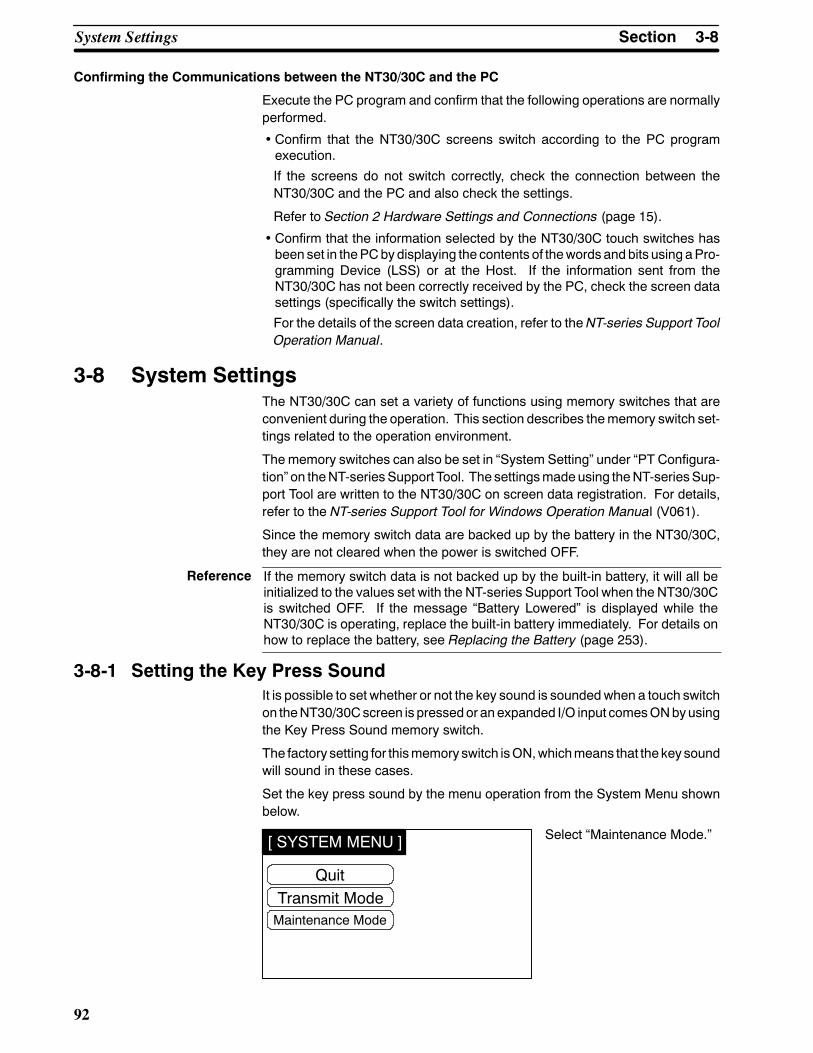
Reference
[ SYSTEM MENU ]
QuitTransmit ModeMaintenance Mode
3-8SectionSystem Settings
92
Confirming the Communications between the NT30/30C and the PC
Execute the PC program and confirm that the following operations are normallyperformed.
• Confirm that the NT30/30C screens switch according to the PC programexecution.
If the screens do not switch correctly, check the connection between theNT30/30C and the PC and also check the settings.
Refer to Section 2 Hardware Settings and Connections (page 15).
• Confirm that the information selected by the NT30/30C touch switches hasbeen set in thePCbydisplaying the contents of thewords and bits using aPro-gramming Device (LSS) or at the Host. If the information sent from theNT30/30C has not been correctly received by the PC, check the screen datasettings (specifically the switch settings).
For the details of the screen data creation, refer to the NT-series Support ToolOperation Manual.
3-8 System SettingsThe NT30/30C can set a variety of functions using memory switches that areconvenient during the operation. This section describes thememory switch set-tings related to the operation environment.
The memory switches can also be set in “System Setting” under “PT Configura-tion” on theNT-series Support Tool. The settingsmadeusing theNT-seriesSup-port Tool are written to the NT30/30C on screen data registration. For details,refer to the NT-series Support Tool for Windows Operation Manual (V061).
Since the memory switch data are backed up by the battery in the NT30/30C,they are not cleared when the power is switched OFF.
If the memory switch data is not backed up by the built-in battery, it will all beinitialized to the values set with the NT-series Support Tool when the NT30/30Cis switched OFF. If the message “Battery Lowered” is displayed while theNT30/30C is operating, replace the built-in battery immediately. For details onhow to replace the battery, see Replacing the Battery (page 253).
3-8-1 Setting the Key Press SoundIt is possible to set whether or not the key sound is soundedwhen a touch switchon theNT30/30Cscreen is pressedor anexpanded I/O input comesONbyusingthe Key Press Sound memory switch.
The factory setting for thismemory switch isON,whichmeans that the key soundwill sound in these cases.
Set the key press sound by the menu operation from the System Menu shownbelow.
Select “Maintenance Mode.”

[ MAINTENANCE MENU ]
QuitDisplay HistoryI/O Check
Memory Switch
PT SettingsInit. Memory
< MEMORY SWITCH >
ONQuit
Buzzer SoundScreen SaverResume Memory Table
ON10min
PrinterNoneESC/P MONO.
Key Press Sound
Next
3-8SectionSystem Settings
93
Select “Memory Switch.”
Each time the Key PressSound touch switch ispressed, the setting optionONalternates with OFF.
To set and quit themenu, press theQuit touch switch. The settingsmade lastwillbe set and the display will return to the Maintenance Menu.
• ON: The key press sound will be given for 0.2 second when a touch switch ispressed.
• OFF: The key press sound will not be given when a touch key is pressed.
3-8-2 Using the BuzzerThe NT30/30C can set a buzzer to indicate the occurrence of an emergency oran NT30/30C error.
Setting the Buzzer Except when the buzzer has been set so as not to sound at all, the buzzer willsound when an error occurs. To set the buzzer to sound in other cases, the fol-lowing two procedures can be used.
S Controlled by the PC
It is possible to control the NT30/30C from the PC to sound the buzzer duringthe operation.
Refer to 5-7 NT30/30C Status Control (page 239).
S Setting the Buzzer as a Screen Data Attribute by Using the NT-seriesSupport Tool
When creating the screen data by using the NT-series Support Tool, set thebuzzer as a screen attribute so that the buzzer will sound. When the screen inwhich this attribute has been set is displayed, theNT30/30Cwill give the buzz-er sound.
If the control by thePCand the display of the screen in which the buzzer attributehas been set are executed simultaneously, the priority is given to the control bythe PC. Refer to the NT-series Support Tool for Windows Operation Manual(V061).
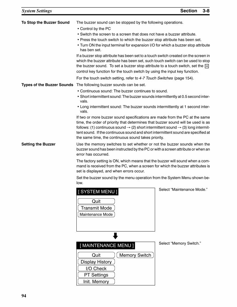
[ SYSTEM MENU ]
QuitTransmit ModeMaintenance Mode
[ MAINTENANCE MENU ]
QuitDisplay HistoryI/O Check
Memory Switch
PT SettingsInit. Memory
3-8SectionSystem Settings
94
To Stop the Buzzer Sound The buzzer sound can be stopped by the following operations.
• Control by the PC• Switch the screen to a screen that does not have a buzzer attribute.• Press the touch switch to which the buzzer stop attribute has been set.• Turn ON the input terminal for expansion I/O for which a buzzer stop attributehas ben set.
If a buzzer stop attribute has been set to a touch switch created on the screen inwhich the buzzer attribute has been set, such touch switch can be used to stopthe buzzer sound. To set a buzzer stop attribute to a touch switch, set thecontrol key function for the touch switch by using the input key function.
For the touch switch setting, refer to 4-7 Touch Switches (page 154).
Types of the Buzzer Sounds The following buzzer sounds can be set.
• Continuous sound: The buzzer continues to sound.• Short intermittent sound: The buzzer sounds intermittently at 0.5 second inter-vals.
• Long intermittent sound: The buzzer sounds intermittently at 1 second inter-vals.
If two or more buzzer sound specifications are made from the PC at the sametime, the order of priority that determines that buzzer sound will be used is asfollows: (1) continuous sound→ (2) short intermittent sound→ (3) long intermit-tent sound. If the continuous sound and short intermittent sound are specified atthe same time, the continuous sound takes priority.
Setting the Buzzer Use the memory switches to set whether or not the buzzer sounds when thebuzzer soundhasbeen instructedby thePCorwith a screenattribute orwhenanerror has occurred.
The factory setting is ON, which means that the buzzer will sound when a com-mand is received from the PC, when a screen for which the buzzer attributes isset is displayed, and when errors occur.
Set the buzzer sound by the menu operation from the System Menu shown be-low.
Select “Maintenance Mode.”
Select “Memory Switch.”

< MEMORY SWITCH >
ONQuit
Buzzer SoundScreen SaverResume Memory Table
ON10min
PrinterNoneESC/P MONO.
Key Press Sound
Next
Reference
Reference
[ SYSTEM MENU ]
QuitTransmit ModeMaintenance Mode
3-8SectionSystem Settings
95
Each time the Buzzer Soundtouch switch is pressed, thesetting option “ON” alternateswith “ERR ON” , “OFF.”
To set and quit the menu, press the Quit touch switch. The setting made last willbe set and the display will return to the Maintenance Menu.
• OFF: The buzzer will not sound at all during the operation.• ON: The buzzer will sound when a command from the PC is given, the screenattribute has been set, or an error has occurred.
• ERR ON: The buzzer will sound only when an error has occurred.
The buzzer will sound when “Buzzer check” is selected in the MaintenanceMode regardless of the buzzer setting.
3-8-3 Screen Saver FunctionTheNT30/30Chas a function that turnsOFF the screen display if no operation isperformed for a certain period of time tomaximize the service life of the backlightand prevent the formation of an afterimage on the screen. (the backlight is alsoswitched OFF at the same time).
Redisplaying a Screen That Has Been Turned OFF
After the screenhasbeen turnedOFFby thescreensaver function itwill be redis-played if a touch switch is pressed, or if an instruction to switch the screen or re-display the samescreen is received from thePC (thebacklightwill also be turnedbackON at the same time). Changes in numerals or character strings displayedon the screen will not cause the screen to be redisplayed.
Setting the Screen Saver Function
Use thememory switches to setwhether or not the screen saver function is used,and the length of time that the screen is turned OFF if it is used.
The factory setting specifies that the backlight will turnOFF if no operation is per-formed for 10 minutes.
When terminals towhich numeric key functions or stand-alone function keysareallocated are turned ON while the backlight is OFF, the key function will not beexecuted by canceling the backlight OFF status. However, in the case of inputcommunication keys, notification will be sent to the PLC regardless of whetheror not there is a backlight OFF function releasing attribute.
Select “Maintenance Mode.”

[ MAINTENANCE MENU ]
QuitDisplay HistoryI/O Check
Memory Switch
PT SettingsInit. Memory
< MEMORY SWITCH >
ONQuit
Buzzer SoundScreen SaverResume Memory Table
ON10min
PrinterNoneESC/P MONO.
Key Press SoundNext
Caution
Correct use
3-8SectionSystem Settings
96
Select “Memory Switch.”
Each time the Screen Savertouch switch is pressed, thesetting option will switchamong 10 min, 1 hour, andNone.
To set and quit the menu, press the Quit touch switch. The setting made last willbe set and the display will return to the Maintenance Menu.
• None: The screen OFF function is not used. As long as no operation is per-formed, the same screen remains to be displayed.
• 10min: The screen will be turned OFF when no operation has been per-formed for 10 minutes.
• 1hour: The backlight or the EL screen will be turned OFF when no operationhas been performed for 1 hour.
Do not press touch switches carelessly while the backlight is OFF or while noth-ing is displayed on the screen. Otherwise the system may operate unpredict-ably.Only press touch switches after confirming system safety.
After images may remain if the same pattern is displayed for a long period(approx. 1 hour).To prevent the formation of an afterimage, either use the screen saver functionor periodically switch screens.
3-8-4 Resume FunctionTheNT30/30Chas a function to protect the contents of thememory tables (valuesetting key input, data from the PC, etc.) from being erased even if the power tothe NT30/30C is shut OFF during operation. This function is called the resumefunction. Setting the resume function protects thememory tables from being ini-tialized evenwhen the power is turnedONor reset or when themode is switchedto the RUN mode by the System Menu operation.
The screen displayed before the power is turned OFF will be displayed againwhen the NT30/30C is started next time.
If thememory tables are selected in the InitializeMemoryMenu from theMainte-nanceModeMenu, thememory tableswill be initialized regardless of whether or

Reference
[ SYSTEM MENU ]
QuitTransmit ModeMaintenance Mode
[ MAINTENANCE MENU ]
QuitDisplay HistoryI/O Check
Memory Switch
PT SettingsInit. Memory
< MEMORY SWITCH >
ONQuit
Buzzer SoundScreen SaverResume Memory Table
ON10min
PrinterNoneESC/P MONO.
Key Press Sound
Next
3-8SectionSystem Settings
97
not the resume function is set to ON or NONE. For the memory table initializa-tion, refer to Initialization of the Memory Tables (page 81).
If the voltage of the battery in the NT30/30C gets too low, the contents of thememory tables cannot be saved even if the resume function is effective.
Use the memory switches to set whether or not the resume function is used.The factory setting is ON, which means that the resume function is effective.
Set the resume function by using the menu operation from the System Menushown below.
Select “Maintenance Mode.”
Select “Memory Switch.”
Each time the Resume Func-tion touch switch is pressed,the setting option ON alter-nates with None.
To set and quit the menu, press the Quit touch switch. The setting made last willbe set and the display will return to the Maintenance Menu.
• NONE: The resume function will be disabled and the memory tables will beinitialized when the power to the NT30/30C is turned ON or reset or when themode is switched to the RUN mode.
• ON: The resume functionwill be enabled and thememory tableswill not beinitialized. When the NT30/30C starts operation, the contents of the memorytables are written to the allocated words in the PC.

[ SYSTEM MENU ]
QuitTransmit ModeMaintenance Mode
[ MAINTENANCE MENU ]
QuitDisplay HistoryI/O Check
Memory Switch
PT SettingsInit. Memory
3-8SectionSystem Settings
98
3-8-5 Screen Printing FunctionTheNT30/30C can print a hard copy of the displayed screens onto a printer con-nected to theNT30/30C. This function is called the screen printing function. TheNT30/30C will continue operating even when such a hard copy is being printed.
However, since the screen print function shares the NT30/30Cmemory with thepop-up window function (page 173), hard copies cannot be printed while a pop-up window is displayed.
For printer connection, refer to 2-8 Connecting a Printer (page 63).
Printing Screens Screen printing can be performed by using a touch switch for which screen print-ing/interruption function is set or by giving a screen printing command from thePC.
S Using a Touch Switch
When creating screen data with the NT-series Support Tool, set the screenprinting function to a touch switch. For details, refer toNT-series Support Toolfor Windows Operation Manual (V061).
Pressing the touchswitch soset as to start hard copyprintingprintsahardcopyof the screen displayed. To interrupt the printing, press the touch switch towhich hard copy printing interruption is set.
S Giving Instructions from the PC
Set up a PT Status Control Area (PC→ PT) and then start printing the screen.
For details, refer to 5-7 NT30/30C Status Control (page 239).
However, printing of screen hard copies may not be interrupted from the PC.
Setting Screen Printing Set the type of the printer and a way of printing in the Memory Switch Menu.
The factory setting is “ESC/P COL.” (if using an NT30, monochrome printing willbe executed on color printers).
Screen printing by using the menu operation from the System Menu shown be-low.
Select “Maintenance Mode.”
Select “Memory Switch.”

< MEMORY SWITCH >
ONQuit
Buzzer SoundScreen SaverResume Memory Table
ON10min
PrinterNoneESC/P COL.
Key Press Sound
Next
3-8SectionSystem Settings
99
Each time the Printer touchswitch is pressed, the nextitem in the applicable cycle ofoptions below is selected:
ESC/P COL.ESC/P MONO.PR201H COL.PR201H TONE.
To set and quit the menu, press the Quit touch switch. The setting made last willbe set and the display will return to the Maintenance Menu.
ESC/P COL.: Specify this for a printer, such as the EPSON ESC/P Printer(24-pin), that conforms to the printer control standardESC/P24-J83C. Hard copies will be made in colors.
PR201H COL.: Specify this for a printer that conforms to the control standardfor thePC-PR201HmadebyNEC. Hard copieswill bemadein colors.
ESC/P MONO.: Specify this for a printer, such as the EPSON ESC/P Printer(24-pin), that conforms to the printer control standardESC/P24-J82. Hard copies will be made in monochromewith colors expressed by gray scale levels.
PRO201H MONO.:Specify this for a printer that conforms to the control standardfor thePC-PR201HmadebyNEC. Hard copieswill bemadein monochrome with colors expressed by gray scale levels.

3-9SectionSystem Maintenance
100
3-9 System MaintenanceThe NT30/30C has self-maintenance functions, such as display history record-ing, I/O check and PT setting display.
3-9-1 Using the Display History Recording FunctionThedisplayhistory recording function is used to record thedisplay sequenceandfrequency of screens during operation. The data recorded can be displayed andconfirmed on the system screen.
Recording Display History Display history is recorded in the following procedure:
Setting screen attributes
Initializing memory for display history recording
Recording display history
To create a screen, of which display history will be recorded, on the NT-series Sup-port Tool, set display history recording attributes to it. Register a message describ-ing display history with not more than 16 characters (note that although 24 charac-ters can be input using the NT-series Support Tool, only the first 16 are valid).The display history can be recorded if the display history recording attributes for thescreen have been set. For further information, refer to the NT-series Support Toolfor Windows Operation Manual (V061).
Prior to recording, initialize the memory for display history recording(refer to page 82).
When the screen with display history recording attributes requested from the PCappears during operation, the display history will be recorded in the system.
Display History Recording Format
Display history includes the following items related to the screen displayed:
• Screen number
• Date and time of display
• Message outlining screen data
Maximum Number of Screens to be Recorded
In order of occurrence: Up to 1,023 screens can be recorded regardless of thescreen number.
In order of frequency: Up to 1,023 screens can be recorded and number oftimes each screen is displayed can be recorded up to amaximum of 255.
Since the data recorded is retained by the battery, it will not be lost even if thepower to the system is turned OFF.
Confirming Screen Data Recorded
There are twoways to confirm screen data recorded: by themaintenancemode,and by displaying the screen by the screen data recording function during opera-tion.
Recorded data can be displayed in order of occurrence or frequency.

[ SYSTEM MENU ]
QuitTransmit ModeMaintenance Mode
3-9SectionSystem Maintenance
101
- In Order of Occurrence
Recorded data is displayed in order of occurrence.
Screen# ( Y/ M/ D H: Mi) (X) Message1 ( 93/ 5/ 30 23: 30) ( )2 ( 93/ 5/ 31 02: 17) ( )8 ( 93/ 5/ 31 11: 05) ( )
2000 ( 93/ 5/ 31 21: 48) ( )Quit
- In Order of Frequency
Recorded data is displayed in order of display frequency with the accumu-lated number of times each screen has been displayed.
Screen# ( Y/ M/ D H: Mi) (X) Message8 ( / / : ) (255)2 ( / / : ) ( 20)1 ( / / : ) ( 3)
2000 ( / / : ) ( 1)Quit
In either case, the system screen shows up to 14 screen numbers and theirdata at a time.
To take a look at data that is not on the display, press the or key on thetouch panel.
When no screen data is recorded, themessage “HistoryRecordNot Found”appears, and the screen returns to the history record after about two se-conds.
- ConfirmingRecordedScreenDatabyOperation fromtheSystemMenu
Confirm the recorded screen data by the operation from the System Menushown below.
Select “Maintenance Mode.”

[ MAINTENANCE MENU ]
QuitDisplay HistoryI/O Check
Memory Switch
PT SettingsInit. Memory
[ History Record ]
QuitOccurrenceFrequency
3-9SectionSystem Maintenance
102
Select “Display History.”
Select “Occurrence” or “Fre-quency.”
The recorded data will be dis-played in accordance with theselected method.
To quit confirmation, press the Quit touch switch. The History Record menuwill be redisplayed.

Reference
[ SYSTEM MENU ]
QuitTransmit ModeMaintenance Mode
3-9SectionSystem Maintenance
103
- Confirming Recorded Screen Data During Operation
Screens No. 1997 and No. 1998 are for displaying recorded screen data.
Either screen will be displayed according to the data display order selected.
Screen No. 1997: In order of occurrenceScreen No. 1998: In order of frequency
S When the direct connection system is used, screensNo. 1997 andNo.1998 arereserved for recorded screen data display. They are unavailable for any otherpurpose.
S If the screen attribute (numeral setting attribute) for screen numbers 1997 and1998 is “user,” the touch switches used to scroll the screen do not appear whenthe display history is displayed during operation. In this case, create touchswitches -- such as the and touch switches shown in the figure below -- inadvance at the right edge of the screen. The size of the switches should notexceed40dots (two regular touchswitchwidths). WhenusinganNT30C,selectwhite as the background color for the screen.
3-9-2 I/O CheckThe I/O operations for the following items of the NT30/30C are checked by theI/O check function.
• Expansion I/O Unit (B7A Unit): Buzzer Check• Touch Switch: LED Check• Communication Check: Calendar & Clock• LCD Display: Battery Voltage• Backlight: Printer Check
Checking the Expanded I/O Checkexpanded I/OonaB7AUnit by using themenuoperation from theSystemMenu shown below.
Select “Maintenance Mode.”
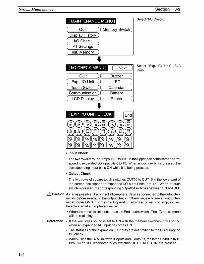
[ MAINTENANCE MENU ]
QuitDisplay HistoryI/O Check
Memory Switch
PT SettingsInit. Memory
[ I/O CHECK MENU ]
QuitExp. I/O UnitTouch Switch
BuzzerLED
CommunicationLCD Display
Next
CalendarBatteryPrinter
[ EXP. I/O UNIT CHECK ] End
IN00
IN01
IN02
IN03
IN04
IN05
IN06
IN07
IN08
IN09
IN10
IN11
IN12
IN13
IN14
IN15
OUT00
OUT01
OUT02
OUT03
OUT04
OUT05
OUT06
OUT07
OUT08
OUT09
OUT10
OUT11
OUT12
OUT13
OUT14
OUT15
Caution
Reference
3-9SectionSystem Maintenance
104
Select “I/O Check.”
Select “Exp. I/O Unit” (B7AUnit).
S Input Check
The two rows of round lamps IN00 to IN15 in the upper part of the screen corre-spond to expanded I/O input bits 0 to 15. When a touch switch is pressed, thecorresponding input bit is ON while it is being pressed.
S Output Check
The two rows of square touch switches OUT00 to OUT15 in the lower part ofthe screen correspond to expanded I/O output bits 0 to 15. When a touchswitch is pressed, thecorrespondingoutput bit switchesbetweenONandOFF.
As far as possible, disconnect all peripheral devices connected to the output ter-minals before executing the output check. Otherwise, each time an output ter-minal comesON during the check operation, a buzzer, or warning lamp, etc. willbe activated at a peripheral device.
•When the check is finished, press the End touch switch. The I/O check menuwill be redisplayed.
S If the key press sound is set to ON with the memory switches, it will soundwhen an expanded I/O input bit comes ON.
S The statuses of the expansion I/O inputs are not notified to the PC during theI/O check.
S When using the B7A Unit with 8 inputs and 8 outputs, the lamps IN08 to IN15turn ON or OFF whenever touch switches OUT00 to OUT07 are pressed.

[ SYSTEM MENU ]
QuitTransmit ModeMaintenance Mode
[ MAINTENANCE MENU ]
QuitDisplay HistoryI/O Check
Memory Switch
PT SettingsInit. Memory
[ I/O CHECK MENU ]
QuitExp. I/O UnitTouch Switch
BuzzerLED
CommunicationLCD Display
Next
CalendarBatteryPrinter
Reference
3-9SectionSystem Maintenance
105
Checking the Touch Switches
Execute a touch switch check by the menu operation from the System Menushown below.
Select “Maintenance Mode.”
Select “I/O Check.”
Select “Touch Switch.”
This touch switch is to exit thetouch switch checking screen. Itscolor is different from that of theother switches.The touch switch is normal if itis highlighted while it is pressed.
• Press a touch switch on the screen. If the touch switch is highlighted while it ispressed, the touch switch is normally functioning.
•When the check is finished, press the 1x1 touch switch at the top right corner ofthe screen. The I/O check menu will be redisplayed.
If memory switch setting for the key press sound has beenmade forON, the keypress sound will be made when a touch switch is pressed. The number ofpressed touch switch will not be notified to the PC.

[ SYSTEM MENU ]
QuitTransmit ModeMaintenance Mode
[ MAINTENANCE MENU ]
QuitDisplay HistoryI/O Check
Memory Switch
PT SettingsInit. Memory
[ I/O CHECK MENU ]
QuitExp. I/O UnitTouch Switch
BuzzerLED
CommunicationLCD Display
Next
CalendarBatteryPrinter
[ COMMUNICATION CHECK MENU ]
QuitRS232CRS422
Set up the PLC of “host link”, “9600 bps”,“2 stop bits”, and “even parity”
3-9SectionSystem Maintenance
106
Checking the Communications with PC
Execute a NT30/30C-to-PC communication check by the menu operation fromthe System Menu shown below.
TheNT30/30Cuses the sameconnector for connection to theNT-seriesSupportTool and RS-232C connection to the PC. To establish an RS-232C connectionwith thePC, disconnect the cable from theNT-series Support Tool and connect itto the PC: the communication check can then be performed.
Select “Maintenance Mode.”
Select “I/O Check.”
Select “Communication.”
Select “RS232C” or “RS422 .”
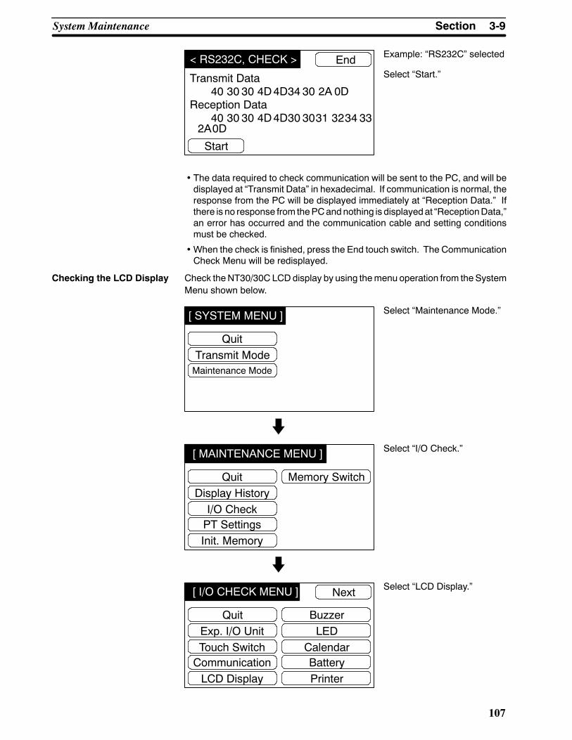
< RS232C, CHECK >
Start
End
Transmit Data
Reception Data40 30 30 4D4D34 30 2A
40 30 30 4D4D30 3031 3234 332A
0D
0D
[ SYSTEM MENU ]
QuitTransmit ModeMaintenance Mode
[ MAINTENANCE MENU ]
QuitDisplay HistoryI/O Check
Memory Switch
PT SettingsInit. Memory
[ I/O CHECK MENU ]
QuitExp. I/O UnitTouch Switch
BuzzerLED
CommunicationLCD Display
Next
CalendarBatteryPrinter
3-9SectionSystem Maintenance
107
Example: “RS232C” selected
Select “Start.”
• The data required to check communication will be sent to the PC, and will bedisplayed at “Transmit Data” in hexadecimal. If communication is normal, theresponse from the PC will be displayed immediately at “Reception Data.” Ifthere is no response from thePCandnothing is displayedat “ReceptionData,”an error has occurred and the communication cable and setting conditionsmust be checked.
•When the check is finished, press the End touch switch. The CommunicationCheck Menu will be redisplayed.
Checking the LCD Display Check theNT30/30C LCDdisplay by using themenu operation from the SystemMenu shown below.
Select “Maintenance Mode.”
Select “I/O Check.”
Select “LCD Display.”

[ SYSTEM MENU ]
QuitTransmit ModeMaintenance Mode
[ MAINTENANCE MENU ]
QuitDisplay HistoryI/O Check
Memory Switch
PT SettingsInit. Memory
[ I/O CHECK MENU ]
QuitExp. I/O UnitTouch Switch
BuzzerLED
CommunicationLCD Display
Next
CalendarBatteryPrinter
Reference
3-9SectionSystem Maintenance
108
• Dots (the points that make up the screen) are displayed one by one starting atthe top left of the screen. In the case of the NT30C, the check is performed foreachcolor (in theorder black→blue→magenta→white→ yellow→green→black). If all the dots are displayed successfully, the display is cleared and theI/O Check Menu is redisplayed.
• To discontinue a screen display check, press the touch switch at the top rightcorner of the screen. The I/O Check Menu” will be redisplayed.
Checking the Buzzer Check theNT30/30Cbuzzer byusing themenuoperation from theSystemMenushown below.
Select “Maintenance Mode.”
Select “I/O Check.”
Select “Buzzer.”
• If the buzzer function is normal, the continuous buzzer sound will be made.
• To stop the buzzer sounding, press the Buzzer touch switch again.
Thoughmemory switch setting for the buzzer has beenmade forOFF, the buzz-er will sound when the buzzer check is executed.

[ SYSTEM MENU ]
QuitTransmit ModeMaintenance Mode
[ MAINTENANCE MENU ]
QuitDisplay HistoryI/O Check
Memory Switch
PT SettingsInit. Memory
[ I/O CHECK MENU ]
QuitExp. I/O UnitTouch Switch
BuzzerLED
CommunicationLCD Display
Next
CalendarBatteryPrinter
3-9SectionSystem Maintenance
109
Checking the Indicators Check the indicators by using themenu operation from the SystemMenu shownbelow.
Select “Maintenance Mode.”
Select “I/O Check.”
Select “LED.”
The RUN indicator on the front face of the NT30/30C will flash alternately greenand red. The POWER indicator remains lit.
• To quit the indicator check, press the LED Check touch switch again.

[ SYSTEM MENU ]
QuitTransmit ModeMaintenance Mode
[ MAINTENANCE MENU ]
QuitDisplay HistoryI/O Check
Memory Switch
PT SettingsInit. Memory
[ I/O CHECK MENU ]
QuitExp. I/O UnitTouch Switch
BuzzerLED
CommunicationLCD Display
Next
CalendarBatteryPrinter
04/15/95 14 : 39 : 07
Quit< CALENDAR CHECK >
3-9SectionSystem Maintenance
110
Checking the Calendar and Time
Check the setting of the internal clock function by using themenu operation fromthe System Menu shown below.
Select “Maintenance Mode.”
Select “I/O Check.”
Select “Calendar.”
•When the check is finished, press the Quit touch switch. The I/O CheckMenuwill be redisplayed.
• Calendar and clock setting can also be executed by performing the downloadoperation in “Date and Time” under “Connect” on the NT-series Support Tool,or by usingnumeralmemory table operations. For details on the settingproce-dure when using the NT-series Support Tool, refer to the NT-series SupportTool for Windows OperationManual (V061), and for details on the setting pro-cedure using numeral memory table, refer to 5-6 Clock Function (page 234).

[ SYSTEM MENU ]
QuitTransmit ModeMaintenance Mode
[ MAINTENANCE MENU ]
QuitDisplay HistoryI/O Check
Memory Switch
PT SettingsInit. Memory
[ I/O CHECK MENU ]
QuitExp. I/O UnitTouch Switch
BuzzerLED
CommunicationLCD Display
Next
CalendarBatteryPrinter
Quit< BATTERY CHECK >
Normal
3-9SectionSystem Maintenance
111
Checking the Battery Voltage
Check the battery voltage by using the menu operation from the System Menushown below.
Select “Maintenance Mode.”
Select “I/O Check.”
Select “Battery.”
• After checking the screen message, press the Quit touch switch. The I/OCheck Menu will be redisplayed.

[ SYSTEM MENU ]
QuitTransmit ModeMaintenance Mode
[ MAINTENANCE MENU ]
QuitDisplay HistoryI/O Check
Memory Switch
PT SettingsInit. Memory
[ I/O CHECK MENU ]
QuitExp. I/O UnitTouch Switch
BuzzerLED
CommunicationLCD Display
Next
CalendarBatteryPrinter
Quit< PRINTER CHECK >
Start
3-9SectionSystem Maintenance
112
Checking the Printer
Check communicationwith theprinter by using themenuoperation from theSys-tem Menu shown below.
Select “Maintenance Mode.”
Select “I/O Check.”
Select “Printer.”
Press “Start.”
“PRINTER CHECK” will beprinted out at the connectedprinter.
• On completion of the check, the message “Finish Check” will be displayed.
• Onconfirming the result, press theQuit touch switch. The I/OCheckMenuwillbe redisplayed.
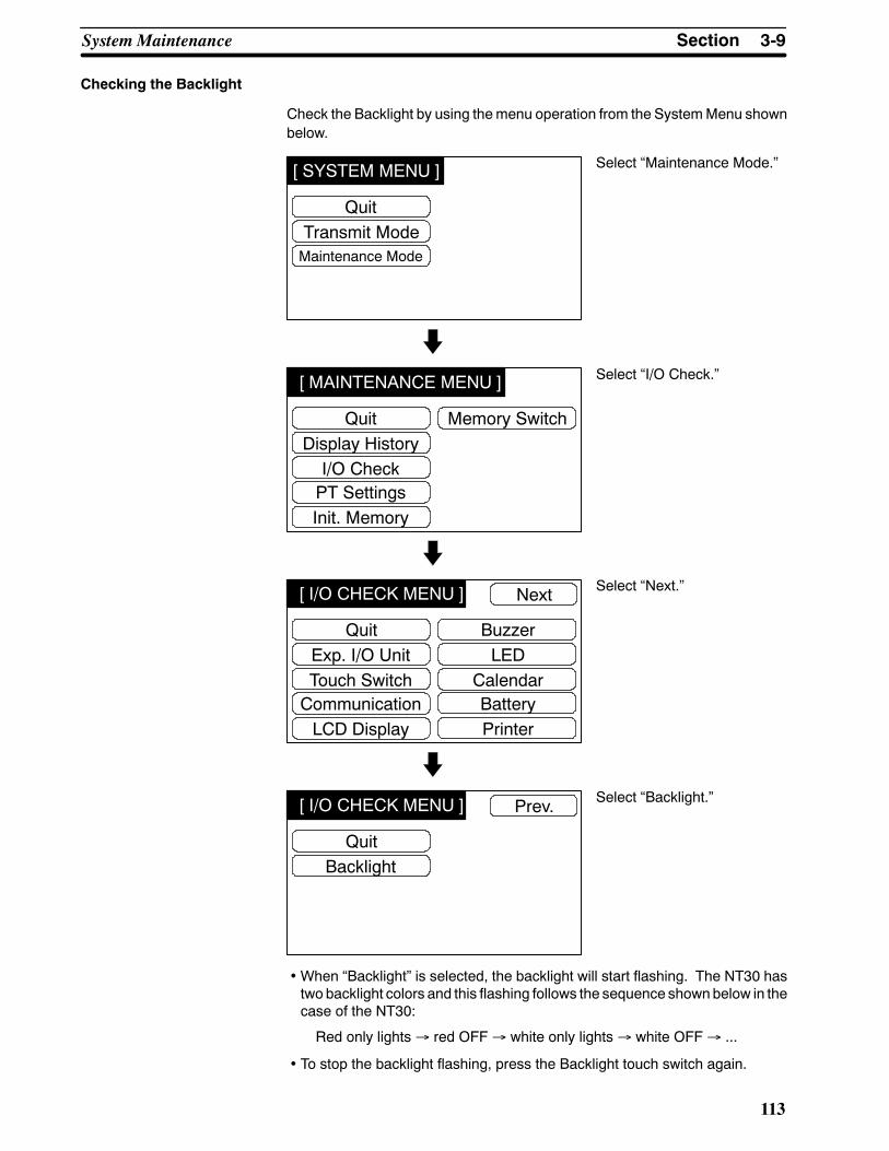
[ SYSTEM MENU ]
QuitTransmit ModeMaintenance Mode
[ MAINTENANCE MENU ]
QuitDisplay HistoryI/O Check
Memory Switch
PT SettingsInit. Memory
[ I/O CHECK MENU ]
QuitExp. I/O UnitTouch Switch
BuzzerLED
CommunicationLCD Display
Next
CalendarBatteryPrinter
[ I/O CHECK MENU ]
QuitBacklight
Prev.
3-9SectionSystem Maintenance
113
Checking the Backlight
Check the Backlight by using themenu operation from the SystemMenu shownbelow.
Select “Maintenance Mode.”
Select “I/O Check.”
Select “Next.”
Select “Backlight.”
•When “Backlight” is selected, the backlight will start flashing. The NT30 hastwo backlight colors and this flashing follows the sequence shownbelow in thecase of the NT30:
Red only lights→ red OFF→ white only lights→ white OFF→ ...
• To stop the backlight flashing, press the Backlight touch switch again.

[ SYSTEM MENU ]
QuitTransmit ModeMaintenance Mode
[ MAINTENANCE MENU ]
QuitDisplay HistoryI/O Check
Memory Switch
PT SettingsInit. Memory
Quit< PT SETTINGS >Screen Memory Size 512kPT Control Area
ONPT Notify AreaSW2-1 System ReservedSW2-2ON:Memory ProtectSW2-3ON:Not Display System MenuSW2-4ON:Init. Screen MemorySW2-5 System ReservedSW2-6 System ReservedSW2-7ON:Erase System ProgramSW2-8 For the Terminater Valid, Turn ON
OFF
DM0100DM0200
Reference
3-9SectionSystem Maintenance
114
3-9-3 Checking the PT Setting StatusChecking the PT Setting Status
Display the NT30/30C settings by using the menu operation from the SystemMenu shown below.
Select “Maintenance Mode.”
Select “PT Settings.”
• The current NT30/30C setting status will be displayed.• Pressing the Quit touch switch will exit the PT Settings display and cause theNT30/30C to return to the Maintenance Menu.
SW2 pin 6 is factory-set to OFF. Since it is not possible to display English withthis setting, it must be set to ON before installing the system program. (Use theinstaller.)
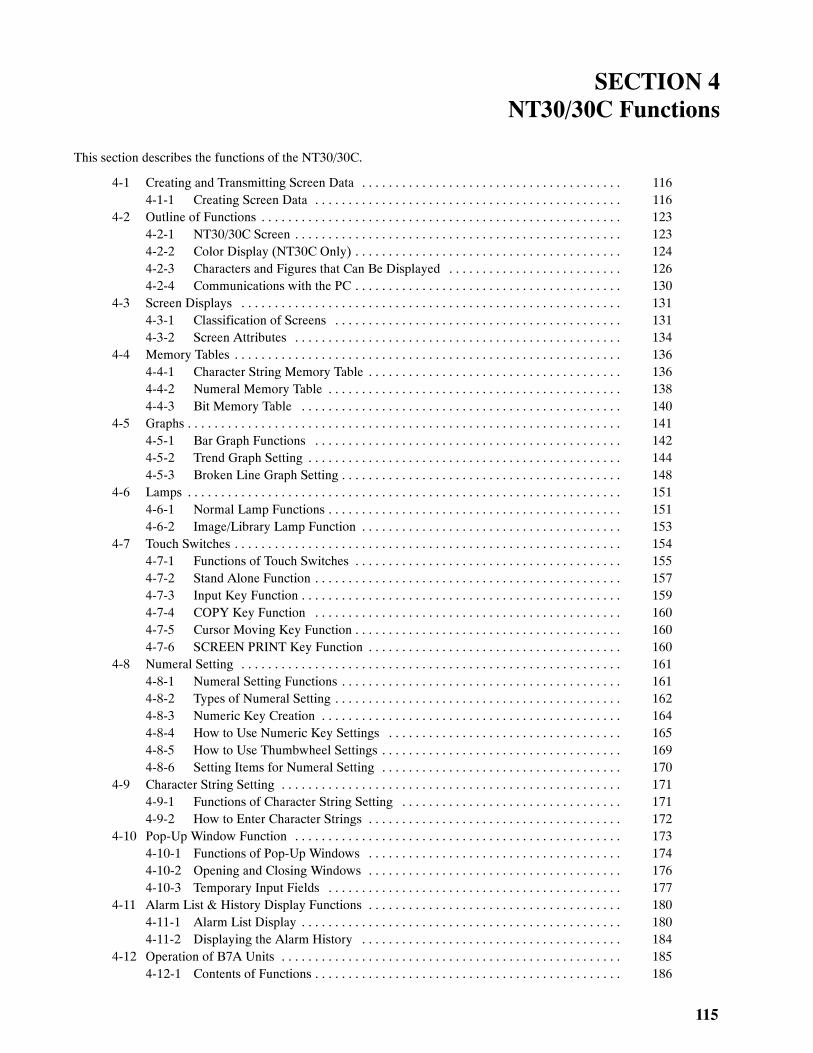
115
SECTION 4NT30/30C Functions
This section describes the functions of the NT30/30C.
4-1 Creating and Transmitting Screen Data 116. . . . . . . . . . . . . . . . . . . . . . . . . . . . . . . . . . . . . . .4-1-1 Creating Screen Data 116. . . . . . . . . . . . . . . . . . . . . . . . . . . . . . . . . . . . . . . . . . . . . .
4-2 Outline of Functions 123. . . . . . . . . . . . . . . . . . . . . . . . . . . . . . . . . . . . . . . . . . . . . . . . . . . . . .4-2-1 NT30/30C Screen 123. . . . . . . . . . . . . . . . . . . . . . . . . . . . . . . . . . . . . . . . . . . . . . . . .4-2-2 Color Display (NT30C Only) 124. . . . . . . . . . . . . . . . . . . . . . . . . . . . . . . . . . . . . . . .4-2-3 Characters and Figures that Can Be Displayed 126. . . . . . . . . . . . . . . . . . . . . . . . . .4-2-4 Communications with the PC 130. . . . . . . . . . . . . . . . . . . . . . . . . . . . . . . . . . . . . . . .
4-3 Screen Displays 131. . . . . . . . . . . . . . . . . . . . . . . . . . . . . . . . . . . . . . . . . . . . . . . . . . . . . . . . .4-3-1 Classification of Screens 131. . . . . . . . . . . . . . . . . . . . . . . . . . . . . . . . . . . . . . . . . . .4-3-2 Screen Attributes 134. . . . . . . . . . . . . . . . . . . . . . . . . . . . . . . . . . . . . . . . . . . . . . . . .
4-4 Memory Tables 136. . . . . . . . . . . . . . . . . . . . . . . . . . . . . . . . . . . . . . . . . . . . . . . . . . . . . . . . . .4-4-1 Character String Memory Table 136. . . . . . . . . . . . . . . . . . . . . . . . . . . . . . . . . . . . . .4-4-2 Numeral Memory Table 138. . . . . . . . . . . . . . . . . . . . . . . . . . . . . . . . . . . . . . . . . . . .4-4-3 Bit Memory Table 140. . . . . . . . . . . . . . . . . . . . . . . . . . . . . . . . . . . . . . . . . . . . . . . .
4-5 Graphs 141. . . . . . . . . . . . . . . . . . . . . . . . . . . . . . . . . . . . . . . . . . . . . . . . . . . . . . . . . . . . . . . . .4-5-1 Bar Graph Functions 142. . . . . . . . . . . . . . . . . . . . . . . . . . . . . . . . . . . . . . . . . . . . . .4-5-2 Trend Graph Setting 144. . . . . . . . . . . . . . . . . . . . . . . . . . . . . . . . . . . . . . . . . . . . . . .4-5-3 Broken Line Graph Setting 148. . . . . . . . . . . . . . . . . . . . . . . . . . . . . . . . . . . . . . . . . .
4-6 Lamps 151. . . . . . . . . . . . . . . . . . . . . . . . . . . . . . . . . . . . . . . . . . . . . . . . . . . . . . . . . . . . . . . . .4-6-1 Normal Lamp Functions 151. . . . . . . . . . . . . . . . . . . . . . . . . . . . . . . . . . . . . . . . . . . .4-6-2 Image/Library Lamp Function 153. . . . . . . . . . . . . . . . . . . . . . . . . . . . . . . . . . . . . . .
4-7 Touch Switches 154. . . . . . . . . . . . . . . . . . . . . . . . . . . . . . . . . . . . . . . . . . . . . . . . . . . . . . . . . .4-7-1 Functions of Touch Switches 155. . . . . . . . . . . . . . . . . . . . . . . . . . . . . . . . . . . . . . . .4-7-2 Stand Alone Function 157. . . . . . . . . . . . . . . . . . . . . . . . . . . . . . . . . . . . . . . . . . . . . .4-7-3 Input Key Function 159. . . . . . . . . . . . . . . . . . . . . . . . . . . . . . . . . . . . . . . . . . . . . . . .4-7-4 COPY Key Function 160. . . . . . . . . . . . . . . . . . . . . . . . . . . . . . . . . . . . . . . . . . . . . .4-7-5 Cursor Moving Key Function 160. . . . . . . . . . . . . . . . . . . . . . . . . . . . . . . . . . . . . . . .4-7-6 SCREEN PRINT Key Function 160. . . . . . . . . . . . . . . . . . . . . . . . . . . . . . . . . . . . . .
4-8 Numeral Setting 161. . . . . . . . . . . . . . . . . . . . . . . . . . . . . . . . . . . . . . . . . . . . . . . . . . . . . . . . .4-8-1 Numeral Setting Functions 161. . . . . . . . . . . . . . . . . . . . . . . . . . . . . . . . . . . . . . . . . .4-8-2 Types of Numeral Setting 162. . . . . . . . . . . . . . . . . . . . . . . . . . . . . . . . . . . . . . . . . . .4-8-3 Numeric Key Creation 164. . . . . . . . . . . . . . . . . . . . . . . . . . . . . . . . . . . . . . . . . . . . .4-8-4 How to Use Numeric Key Settings 165. . . . . . . . . . . . . . . . . . . . . . . . . . . . . . . . . . .4-8-5 How to Use Thumbwheel Settings 169. . . . . . . . . . . . . . . . . . . . . . . . . . . . . . . . . . . .4-8-6 Setting Items for Numeral Setting 170. . . . . . . . . . . . . . . . . . . . . . . . . . . . . . . . . . . .
4-9 Character String Setting 171. . . . . . . . . . . . . . . . . . . . . . . . . . . . . . . . . . . . . . . . . . . . . . . . . . .4-9-1 Functions of Character String Setting 171. . . . . . . . . . . . . . . . . . . . . . . . . . . . . . . . .4-9-2 How to Enter Character Strings 172. . . . . . . . . . . . . . . . . . . . . . . . . . . . . . . . . . . . . .
4-10 Pop-Up Window Function 173. . . . . . . . . . . . . . . . . . . . . . . . . . . . . . . . . . . . . . . . . . . . . . . . .4-10-1 Functions of Pop-Up Windows 174. . . . . . . . . . . . . . . . . . . . . . . . . . . . . . . . . . . . . .4-10-2 Opening and Closing Windows 176. . . . . . . . . . . . . . . . . . . . . . . . . . . . . . . . . . . . . .4-10-3 Temporary Input Fields 177. . . . . . . . . . . . . . . . . . . . . . . . . . . . . . . . . . . . . . . . . . . .
4-11 Alarm List & History Display Functions 180. . . . . . . . . . . . . . . . . . . . . . . . . . . . . . . . . . . . . .4-11-1 Alarm List Display 180. . . . . . . . . . . . . . . . . . . . . . . . . . . . . . . . . . . . . . . . . . . . . . . .4-11-2 Displaying the Alarm History 184. . . . . . . . . . . . . . . . . . . . . . . . . . . . . . . . . . . . . . .
4-12 Operation of B7A Units 185. . . . . . . . . . . . . . . . . . . . . . . . . . . . . . . . . . . . . . . . . . . . . . . . . . .4-12-1 Contents of Functions 186. . . . . . . . . . . . . . . . . . . . . . . . . . . . . . . . . . . . . . . . . . . . . .

4-1SectionCreating and Transmitting Screen Data
116
4-1 Creating and Transmitting Screen DataThis section describes briefly the NT-series Support Tool settings required forcreating screen data and the screen data creation procedure. Screen data mustbe created to use the NT30/NT30C
For the details of the NT-series Support Tool and screen data creation, refer tothe NT-series Support Tool for Windows Operation Manual (V061). There aresome differences in the displays depending on the version.
4-1-1 Creating Screen DataScreen Data Creation Method
The screen data is created by using the NT-series Support Tool. The NT-seriesSupport Tool registers the screen data used with one NT30/30C to one file.
Screen data can be created by one of the following three methods:
• Creating a new file;• Editing an existing file to create a new.
The same screen data can be used for both the NT30 and NT30C. Also, NT-se-ries Support Tool for Windows can be used to convert screen data from theNT20S, NT620C, or NT625C for use with the NT30 or NT30C. Refer to the NT-series Support Tool for Windows Operation Manual for information on convert-ing screen data between different PT models.NT-series Support Tool for Windows can read screen data created on the DOSversion of the NT-series Support Tool. You can also import individual scenes,components, or tables from screen data files. Refer to the NT-series SupportTool for Windows Operation Manual for details.

4-1SectionCreating and Transmitting Screen Data
117
Screen Data Creation Procedure
The following gives the basic screen data creation procedure. Required settingsand reference pages are given for each step of the procedure.
1, 2, 3... 1. After starting the Support Tool, open a screen file to use for storing thescreen data from the File Menu.
To create a new file, select “New File.” Select “New File” and press [Enter].Enter filename on completion of creation.
To edit an existing file, select “Open” and then select a file to edit.

4-1SectionCreating and Transmitting Screen Data
118
The following PT Configuration Window will appear when “New File” hasbeen selected. (The name of the screen data file is input later.)
2. Set the PT Model to NT30 or NT30C and the PLC Vendor to OMRON andclick the OK Button.
3. Click the System Tab to set the memory switches for the PT. The actualswitch settings in the PT will be made according to the settings made herewhen the data is transferred to the PT.
The following settings can be made.• Startup screen: Startup Screen (page 196)• Number of Table Entries in Numeral Table: 4-4-2 Numeral Memory Table(page 138)

4-1SectionCreating and Transmitting Screen Data
119
• Number of Table Entries in String Table: 4-4-1 Character String MemoryTable (page 136)
• History Setting, Alarm (UseRing Buffer): 4-11-2 Displaying the AlarmHis-tory (page 184)
• Other settings (Number of Table Entries in Bit Memory Table Is Always256): 3-5 Setting Communications with the PC Using Memory Switches(page 83)
4. Click the Control/Notify Area Tab to set the PT Status Control Area and PTStatus Notify Area as described below before selecting the screen number.
• PT Status Control Area: 5-7 NT30/30C Status Control (page 239)• PT Status Notify Area: 5-8 Notification of the Operating Status to the PC(page 244)
5. The following Application Manager will appear when the PT EnvironmentSettings is selected under “New File” or when a file is opened using the

4-1SectionCreating and Transmitting Screen Data
120
Open command. The creation screen for screen number 1 will also be dis-played.
6. From the Application Manager, the screen to be edited can be designated,screens can be copied, and memory tables can be edited.
The following tables can be edited:
• Numeral memory table: Numeral Memory Table (page 138)
• Character string memory table: Character String Memory Table (page136)
• Bit memory table: Bit Memory Table (page 140)
• Expanded I/O: 4-12 Operation of B7A Unit (page 185)
• Mark table: Marks (page 126)
• Image table: Image Data (page 126)
• Library table: Library Data (page 127)
Refer to theNT-seriesSupport Tool forWindowsOperationManual for infor-mation on I/O comments.
7. Thenumbers of the screens that havebeen registeredwill be displayed.Se-lect “Properties” from the ScreenMenu to set the screen attributes. The fol-lowing screen attributes can be set:
• History: No, Yes
• Backlight: Light, flash, or color
• Buzzer: None, Cont (continuous sound), Long (long intermittent sound),Short (short intermittent sound)
• Local 1 Keyboard: Don’t display or window screen number for display
• System Keypad: Use or don’t use
• Back Col
Note Back Col. (background color) can be set only when using an NT30C.The backlight color can be set for the NC30.

4-1SectionCreating and Transmitting Screen Data
121
8. Double-click one of the screen numbers in the ApplicationManager to openthe window to edit screen data.
Data of one screen can be created by registering (laying out) the followingdisplay elements and attributes on the screen.• Fixed displayInput characters and graphics.......................Characters and Figures that Can be Displayed (page 126)
• Numeral display:Set the numeral memory table entry number and display method....................................................Numeral Memory Table (page 138)
• Character string display:Set the character string memory table entry number and display method.........................................Character String Memory Table (page 136)
• Lamp:Set the allocated bit and display method.......................................................4-6 Lamps (page 151)
• Touch switch:Set the functions allocated bits for control and notification, and displaymethod............................................4-7 Touch Switches (page 154)
• Graph:Set the type of graph, numeral memory table entry number, and displaymethod.................................4-5 Graphs (page 141)
• Input setting:Set the numeral/character string memory table entry number............................................4-8 Numeral Setting (page 161).................................4-9 Character String Setting (page 171)
• Alarm:Set the typeof alarm, bitmemory table entry number, anddisplaymethod....................4-11 Alarm List & History Display Functions (page 180)
When you have finished creating the screen data, it is not necessary to re-turn to the Application Manager.

4-1SectionCreating and Transmitting Screen Data
122
9. To successively create another screen, select “New File” and enter thescreen type and screen number.
10. When you have finished creating screen data, select “Save” or “Save as”from the File Menu. “Save” will create a new file or overwrite an existing file.“Save as” can be used to change the name of the file.
11. Enter filename for the newly created screen data.
Transmitting Screen Data to the NT30/30C
Transmit the screen data created by using the NT-series Support Tool to theNT30/30C screen data memory.
Connect the NT30/30C to the NT-series Support Tool and set the NT30/30C toTransmit Mode. Then, press the [F6] (Transmit) key in the File List screen totransmit the created screen data to the NT30/30C.
For the connection procedure to the NT-series Support Tool, refer to 2-3 Con-necting to the NT-series Support Tool (page 21). For the transmission of thescreen data, refer to 3-6 Registering the Screen Data (page 89).

4-2SectionOutline of Functions
123
4-2 Outline of Functions
4-2-1 NT30/30C ScreenThis section gives the outline of the screen, which is the basis of all NT30/30Cfunctions.
For specific operating procedures, such as screen switching, refer to Switchingthe Screen Display (page 195).
Create screendata,whichwill be displayedon the screen, on theNT-seriesSup-port Tool, and register it in the imagedatamemory of theNT30/30C. For registra-tion of screen data, refer to 3-6 Registering the Screen Data (page 89).
Screen Composition
TheNT30/30Cscreen is 320dots horizontally and240dots vertically.Eachdot isset using an X coordinate (horizontal) and a Y coordinate (vertical).
The origin (0, 0) is positioned in the upper left corner of the screen.
X coordinate (horizontal)
Y coordinate(vertical)
Coordinates D(x, y)
319
319, 239239
00
Display Elements
The screen can display the following elements. Each element is called a displayelement.
TARGETPRODUCT
C
EMERGENCYSTOP
MarkImage data
Date and timeFixed characters Touch
switchGraphic Lamp
Character stringsfrom memory table Numeric keys
Numeric valuefrom memorytable
Fixednumeralsetting
Graph
OUTPUT
PRODUCTD
95/04/10 14:10LINE B PRODUC-TION STATUS
Screen Management All screens displayed on the NT30/30C are managed by their screen numbers.
A screen number is assigned when the screen is created on the NT-series Sup-port Tool. Up to 2000 screens can be created, and screen numbers from 1 to2000 can be assigned to them as desired. The screen numbers are very helpfulin switching the screen being displayed to a desired one from the PC, or in speci-fying the screen to be displayed at system startup (called the initial displayscreen).

Reference
4-2SectionOutline of Functions
124
Special Screen Numbers ScreensNo. 0 andNo. 1997 throughNo. 1999 are received for the following spe-cial purposes:
- Screen No. 0
Screen No. 0 is reserved with the system as the no-display screen. Selectthis screen when there is no need to display data on the screen.
- Screen No. 1997
ScreenNo. 1997 is reservedwith the systemas the screen for history recordin order of occurrence. Select this screen to display screen data in order ofoccurrence.
- Screen No. 1998
ScreenNo. 1998 is reservedwith the systemas the screen for history recordin order of frequency. Select this screen to display screen data in order of fre-quency.
- Screen No. 1999
Screen No. 1999 can be defined as the Connecting to Host screen. Withoutregistering this screen, a screenwith themessage “Connecting ToHost” au-tomatically appears when the power is turned ON, or the mode is shifted tooperation. Screens No. 1900 through No. 1979 may be used for windowscreens for the pop-up window function. In other cases, they are usable asnormal screens.
Screens No. 1980 throughNo. 1996 are intended to be used for extension func-tions. If they are used as user screens, it will not be possible to use extensionfunctions.
4-2-2 Color Display (NT30C Only)TheNT30C can display the entire screen and screen elements, such as charac-ters and graphics, in eight different colors. Specify a color as anattribute for eachdisplay element when creating a screen on the NT-series Support Tool.
The NT30 is not capable of color display.
Available Colors The following eight colors can be selected:
Black, blue, red, magenta, green, cyan, yellow, white
The four color combinations below are exclusive ORed. The combination of twoexclusiveORed colorsmeans that if the color of a display element is the sameasthat of the background, it will be displayed in a different color.
Yellow, for example, is exclusive ORed with blue.
Red↔ Cyan Green↔ Magenta Blue↔ Yellow White↔ Black
The following display elements are displayed in the above combinations of col-ors:
• Input area display frame and background colors of numeral and characterstring setting screen (Refer to pages 161 and 171.)
• Lamp colors when they are ON, and lamp guide display character colors(Refer to page 151.)
• Touch switch colors when they are ON, and guide display character colors(Refer to page 154.)
• Display color of eight dots beyond the top of a bar graph, and screen back-ground color (Refer to page 141.)

4-2SectionOutline of Functions
125
Transparent Display When two display elements overlap with each other, the background color of theoverlying element conceals the underlaid display element.
Besides theaboveeight colors, the color “transparency” is available for theback-ground of some display elements.
When transparency is set, nothing appears behind a display element, and thedisplay element or screen background color under it becomes visible.
Background color(transparent)
Normal Display Transparent Display
Graphic undercharacter
Graphic undercharacter
Character Character
Background color
S Display Elements that Can Be Displayed in the Color Transparency
Normal display characters
Lamp (or touch switch) guide display characters
Lamps (or touch switches) when they are OFF
Filled graphic patterns
S Display Elements that Cannot Be Displayed in the Color Transparency
Display character strings from character string memory table
Display numeric values from numeral table
Numeric values and character strings on numeral and character string set-ting screen
Characters indicating percentage (%) on graphs
Color Display of the Screen The background color of the entire screen can be specified. Set the backgroundcolor as a screen attribute when creating screen data on the NT-series SupportTool.
Color Display of Characters The color of characters (character color) and that of the square frame (back-ground color) can be specified.
Background color
Character color
Color Display of Graphics The outline of a graphic can be drawn in a specified color, and the graphic can befilled in a pattern in specified colors.
As filling pattern colors, the display color of the pattern itself, the pattern back-ground color and the filled area boundary line color can be set.
Pattern display color
Pattern background color
Filling
Outline color
Line color

4-2SectionOutline of Functions
126
When a lamp, a touch switch and a graphic are to be displayed in specific colors,part of the frames of the display elements may be invisible because of the com-binationof thebackground,outlineand filling colors.This is aphenomenonpecu-liar to a color LCD, not a failure with the system.
In such a case, change the color combination.
4-2-3 Characters and Figures that Can Be DisplayedThe NT30/30C screen can display characters, figures, and various other ele-ments.
This section describes the types and attributes of the characters and figures thatcan be displayed but that are not changed/do not change on the display.
For the settings, display, and use of the characters, numeric values, and graphsthat change according to the operating status and other conditions, refer to sec-tions starting with 4-4 Memory Tables (page 136).
The power of expression of the screen can be increased by using various attrib-utes, such as the enlarged or reverse display, for the characters and figures.
The character and figure attributes are set in the Edit Screen when creating thescreen data on the NT-series Support Tool.
Types and Attributes of Characters and Figures
The following characters can be input and displayed.
Charactertype
Dots(vertical xhorizontal)
Character setMaximum number of
characters displayed on onescreen (without overwriting)
Half sizecharacter 8 x 8 Alphanumerics and
symbols80 characters x 50 lines(4,000 characters)
Normal sizecharacters 8 x 16 Alphanumerics and
symbols80 characters x 25 lines(2,000 characters)
TheNT30/30C is providedwithmarks, image data, and library data in addition tofixed characters.
S Marks
Amark is agraphic pattern combining16x16, 32x32and64x64dots. The32-dot and 64-dot marks, however, are combinations of 4 (2 x 2) and 16 (4 x 4)16-dot marks, respectively.
Up to 22416-dotmarks canbe registeredononescreendata file as characterswith 2-byte codes FF20H to FFFFH.
64-dot mark
16
16
16
16
16 16
16
16
16-dot mark 32-dot mark
S Image Data
Image data is a set of images in units of 8 x 8 dots ranging from8 x 8 dots to 320x 240 dots (entire screen).

Reference
4-2SectionOutline of Functions
127
Images for registering as image data can be created using the NT-series Sup-port Tool’s imagedata creation functionality. It is alsopossible to download filescreated using commercial image creation software and use them as imagedata for the NT30/30C.
Image data for up to 224 images can be registered on a screen data file using2-byte codes from FE20 to FEFF. The number of images that can actually beregistered will depend on the status of the image data memory.
Basically, image data can be displayed in any position on the screen, however,the entire image may not be displayed in some specific positions.
S Library Data
Library data is image data consisting of multiple characters and graphics inunits of 1 x 1 dot ranging from 1 x 1 to 320 x 240 dots (entire screen).
The creation of library data starts by laying out characters and graphics withattributes on the screen in the same manner as normal screen data.
Next, specify the area to be registered. Only characters and graphics can beextracted from other screen data and registered as library data. Library datacannot be registered as displayed elements.
Even complicateddata can bedisplayed.
Library data
Once registered as library data, complicated images composed of charactersand graphics can be displayed many times easily, and need not be createdagain. The image data memory be used more efficiently by using library data.
Library data for up to 896 images can be registered on a screen data file using2-byte codes FA20 to FAFF, FB20 to FBFF, FC20 to FCFF, and FD20 to FDFF.
Basically, library data can be displayed in any position on the screen. But, in aposition where the entire library data cannot be displayed, it automaticallymoves to another position. Use care in setting a display position.
Difference between Image Data and Library DataWhile image data can take any form as shown in the screen example, onlyimages consisting of characters and graphics can be library data.Because only characters and graphic information are registered as library data,library data requires less memory capacity than image data, for which all thedots to be displayed on the screen must be registered.Imagedata cannot be reversedor flashed,whereas library data canbe reversedor flashed according to the settings for the elements when they are registered.

4-2SectionOutline of Functions
128
S Enlargement of Characters and Marks
Characters andmarks canbeenlarged to the following scales. Image data andlibrary data are exceptions.
Equ Wide High 4x 9x 16x 64x
S Smoothing
Characters (or marks) enlarged to x4 scales or larger are displayed with theoutline automatically smoothed. This function is called smoothing. Image dataand library data cannot be smoothed.
With smoothing Without smoothing
S Color Display (NT30C Only)
Number of color: 8Number of background color: 8 or transparent
S Reverse and Flashing Display
Normal display: Character and background are reversed.
Reverse display: The display brightness of the character andthe background is reversed comparing withthe normal display.
Flashing display: Characters are displayed as they flash. Thenormal display alternates with no-display.
Reverse and flashing display: The reverse display alternates with the nor-mal display.
Image data cannot be inverted, flashed or inverted and flashed alternately.
Library data will be inverted, flashed or inverted and flashed alternately accord-ing to the setting at registration.

4-2SectionOutline of Functions
129
Graphic Types and Their Attributes
On the NT30/30C, the following types of graphic can be entered and dis-played:
Polylines
Circle
Square Polygon
* A continuous straight line withup to 255 middle points can be drawn.
* A polygon with up to 255vertexes can be drawn.
Arc Fan
Designation of line types
Straight lines are available in the following four types:
Solid line
Broken line
1-dot chain line
2-dot chain line
Other graphics can be drawn only with a polyline.
S Filling
The areas of graphics within the outline (closed areas) can be filled in a tilingpattern.
There are ten tiling patters, as shown below:
Name Pattern Name Pattern
Flat Slant right
Box Crosshatch
Slant left Grid
Stripe Border
Diamond Halftone
S Color Display (NT30C Only)
Number of graphic frame colors: 8
Number of display colors (in filling): 8
The tiling pattern colors are display colors.
Number of background colors (in filling): 8 or transparent
The color visible between the blocks of the tiling pattern is the backgroundcolor. When transparent is selected, the display element under the graphicappears to be transparent.
Number of outline colors (in filling): 8

Note
4-2SectionOutline of Functions
130
The color of the boundary line surrounding the area to be filled is the outlinecolor.
Tiling pattern background color
Background color
Tiling pattern display color
When transparent is selected, thescreen background color appearsto be transparent.
Part of the graphic frame may be invisible because of the combination of thedisplay (in filling), backgroundandoutline colors. This phenomenon is peculiarto a color LCD, not a failure with the system.
In such a case, change the color combination.
S Reverse and Flashing Display
Normal display: Only the outline of a graphic is displayed in adesignated color.
Reverse display: A graphic, whose inner contrast of the borderline is reversed, is displayed.
Flashing display: Normal display alternates with no-display.
Reverse and flashing display: Normal display alternates with reverse dis-play.
Continuous straight lines and arcs cannot be inverted, flashed or inverted andflashed alternately.
Filling can be designated only with normal display.
Donot fill graphics towhicha flashingdisplayor inverse flashingdisplayattributehas been set.If a graphic with a flashing display or inverse flashing display attribute is to befilled, the area outside the graphic may be filled in the same pattern when thesystem operates.
4-2-4 Communications with the PCUsing Host Link/NT Link
The NT30/30C can communicate with a PC by using the Host Link or NT Link.Using these functions, bits and words can be allocated to almost any area in PCmemory and data can be written to and read from these bits and words directly.This makes the following functions possible:
Control and notification of screen elements
Control and notification of NT30/30C status
Screen switching
Obtaining the screen number of the currently displayed screen
Memory table operations
For details on the actual operations required for these functions, refer toSection5 Using Host Link/NT Link.

4-3SectionScreen Displays
131
NT30/30C Functions that can be Controlled
The following NT30/30C functions can be controlled.
Screen display: Screens can be displayed and deleted.
Buzzer: Three types of buzzer can be sounded orstopped.
Display history initialization: The display history can be initialized.
Screen printing: The displayed screen can be printed.
Window control: The opening of pop-up windows can be dis-abled.
Numeral/character string input: The input of numerals and character stringscan be disabled.
For details on the actual methods used for these types of control with theNT30/30C, refer to 5-7 NT30/30C Status Control (page 239).
Accessible NT30/30C Operation Status
The following NT30/30C status can be accessed.
Operating status: Whether the NT30/30C is operating or not
Battery voltage: The battery voltage
Screen number: The screen number of the currently displayedscreen
Numeral setting input: Whether a numerical value has been input withthe numeral setting function
Character string setting input Whether a character string has been input withthe character string setting function
Printer operating status Whether the printer is printing or stopped
For the actual methods used to determine the operation status of theNT30/30C,see 5-8 Notifying the PC of the Operating Status (page 244).
Note To ensure system safety, be sure to regularly confirm that the PT is operatingnormally by reading the PT Operating Status Bit at the host.
4-3 Screen DisplaysThis section describes the screen information required for the operation with theNT30/30C.
For the actual method used to change the displayed screen, see Switching theScreen Display (page 197).
For the actualmethod used determine the screen number of a displayed screen,see Notifying the Currently Displayed Screen Number to the PC (page 199).
4-3-1 Classification of ScreensThe NT30/30C is provided with the following types of screens, which are classi-fied by the display method.
• Normal screens• Overlapping screens

4-3SectionScreen Displays
132
• Consecutive screens
The screen type is set for each screen in the Screen List Screen of theNT-seriesSupport Tool. Select the screen type according to the purpose, and create char-acters and figures on the screen. Details on each screen type are given below.
Normal Screens Anormal screen is the basic screenof theNT30/30C. It is not necessary to selecta screen type (overlapping or consecutive) to create screen data for a normalscreen.When a normal screen is selected, the display of existing screens will bestopped and the normal screen will be displayed.
Overlapping Screens Several screens can be overlapped and displayed as one screen. A group ofoverlapped screens is called overlapping screens.
Several screens are displayed in the order of screen numbers to form overlap-ping screens. Up to eight screens can be overlapped. The base screen used formakingoverlapping screens is called theparent screen, and the screens that areoverlapped on the parent screen are called child screens.
Withoverlappingscreens, nodisplayelementsareactually createdon thepatentscreen.Create all display elements on the child screens. Screen attributes, suchas a buzzer attribute, can be set in the parent screen and will be effective in theoverlapping screens.
Example of Overlapping Screens
(1)
(2)
(3)
Screen No. 8
Screen No. 10
Screen No. 7
Screen No. 25
This areoverlappingscreens.
This are
overlapping
screens.
• Parent screen: No. 8• Child screens: No. 10, No. 7, and No. 25
When the parent screen (No. 8) is designated, screenNo. 8 functions as the par-ent screenandchild screensNo. 10,No. 7, andNo. 25aredisplayedoverlappingeach other on the parent screen in order.
Only one numeral setting screen or character string setting screen (screens thatallownumeral and character string inputs on theNT30/30Cscreen) canbe regis-tered as a child screen. For details on numeral settings, see 4-8 Numeral Set-tings (page 161), and for details on character string settings, see 4-9 CharacterString Settings (page 171).
Make sure that touch switches and numbers set in the child screens do not over-lap when the screens are overlapped. If the set positions of the touch switchesand/or numbers in the child screens overlap with each other on the parentscreen, the settings may sometimes not work as intended. Use the NT-seriesSupport Tool and make sure that the set positions do not overlap each other.
Consecutive Screens A group of screens that set up in a specific sequence and can be switched con-secutively are called consecutive screens.Up to eight screens can be registeredas a group of consecutive screens.

Production StatusLine A: NormalLine B: Normal
1/3
→
→
4-3SectionScreen Displays
133
The base screen used for registering the consecutive screens is called the par-ent screen, and the consecutive screens are called child screens.
The current screen number and the total number of consecutive screens can bedisplayed in the top right corner of the screen. This is called the page numberdisplay.
The page number is set when creating the screen data by using the NT-seriesSupport Tool. Refer to the NT-series Support Tool for Windows OperationManual (V061).
With consecutive screens, no display elements are actually created on the pat-ent screen. Create all display elements on the child screens. Screen attributes,such as a buzzer attribute, can be set in the parent screen and will be effective inthe consecutive screens.
Example of Consecutive Screens
1/3
2/3
3/3
Screen No. 20
Screen No. 15
Screen No. 5
Continuousscreen (1)
Continuousscreen (2)
Continuousscreen (3)
[↑] touch switch
[↑] touch switch [↓] touch switch
[↓] touch switch
• Parent screen: No. 10
• Child screens: No. 20, No. 15, and No. 5
When the parent screen (No. 10) is designated, screenNo. 20,which is page1ofthe continuous screens, will be displayed. Screen No. 15 or No. 5 can be dis-played by using the touch switches. Screen No. 10 is the parent screen of thecontinuous screens and thus cannot be displayed as an individual screen.
Switching Continuous Screens Using the Touch Switches
Consecutive screens can be switched by using touch switches to which controlkeys and have been allocated.
If the numeral setting attribute keypadattribute of the parent screen is set to “sys-tem,” the and control keyswill be automatically created as shown in the fig-ures below.

Production StatusLine A: NormalLine B: Normal
1/3
4-3SectionScreen Displays
134
If the numeral setting attribute of the parent screen is set to “user,” create touchswitches and allocate the control keys and to them during screen creation(see Functions of Control Keys, page 159).
4-3-2 Screen AttributesEach screen can be set with a specific function by designating a screen attribute(property), so that the specific function canbeexecutedbydisplaying thescreen.For example, by displaying a screen towhich a buzzer attribute has been set, thebuzzer of the NT30/30C starts sounding.
Set the screen attributes for each screen on the Screen List screen of theNT-se-ries Support Tool.
The DOS version of the NT-series Support Tool displays the bit input and alarmattributes, but these attributes cannot be used with the NT30/30C.
The following several attributes can be set with one screen.
S Buzzer Attribute
This attribute will become effective to sound the buzzer in the NT30/30Cwhenthe screen to which this attribute has been set is displayed. The buzzer soundcan be set as follows:
No: Buzzer does not sound when the screen is displayed.
Continuous sound: Buzzer sounds continuously.
Short: Buzzer sounds intermittently at 0.5-second intervals.
Long: Buzzer sounds intermittently at 1.0-second intervals.
The buzzer sound is set with the NT30/30C memory switch. The buzzer canalso be set by using thePC.Refer toUsing theBuzzer (page 93) for the buzzersetting using the memory switch.
To stop the buzzer by using the screen operation, create a control key as atouch switch.
S Display History Recording Attribute
When a screen with this attribute appears, the screen number, date and time(hour, minute, second), frequency and messages will be recorded as screendata.
Screendata canbe read in themaintenancemodeor on theNT-seriesSupportTool.
Screens No. 1997 and No. 1998 can be used to read the data (see page 184).

4-3SectionScreen Displays
135
S System Keypad (Numeral Setting) Attribute
Select whether the numeric keys are automatically displayed or the numerickeys are created at arbitrary positions on the numeral setting screen. The fol-lowing two numeral setting attributes are used.
System (ON):Thenumeric keysandcontrol keys registered to thesystemareauto-matically displayed.
User (OFF):The numeric keys and control keys can be created at any arbitrarypositions.
With DOS versions of the NT-series Support Tool, “numeral setting” is dis-played.
S Back Col (NT30C only)
Screens for which this attribute has been set are automatically displayed withthe set background color extending over the entire screen.
S Backlight Attributes
Select whether the backlight is lit or flashes when the screen is displayed.When using an NT30, these attributes can be used in conjunction with thebacklight color attribute. Thereare two types of backlight attribute in the screenattributes
Lit: Backlight is lit when the screen is displayed.
Flashing: Backlight flashes when the screen is displayed.
S Backlight Color Attribute (NT30 Only)
Set whether the screen is displayed using the white backlight or the red back-light. This attribute can be used in conjunction with the backlight attributes.
S Load Local 1 (Keyboard) Attribute (Windows Version Only)
Specifywhether or not awindow isdisplayedsimultaneouslywith thedisplayofthe screen (initial window), and specify the screen number of the window.
This screen attribute is not available with the DOS version of the NT-seriesSupport Tool. (Set in Show Window/Keyboard under Input Settings.)

4-4SectionMemory Tables
136
4-4 Memory Tables
TheNT30/30Chas threememory areas that canbewritten to andupdatedby thePC. There is a character string memory table for character data, a numeralmemory table for numerical data, and a bit memory table for bit data.
The contents of the memory tables can also be set using the NT-series SupportTool by displaying a memory table entry on the screen or by editing a memorytable.
4-4-1 Character String Memory Table
The character stringmemory table is anNT30/30C internalmemory area used tostore character data. Up to 1,000 character string memory table entries can beused, and up to 40 characters (40 bytes) can be stored in each memory tableentry. Character string memory table entries can be registered at up to 50 posi-tions on one screen.
Number of Entries
Set the number of character string memory table entries in “System Setting”(“SystemMemory” for DOSversions) under “PTConfiguration” on theNT-seriesSupport Tool.
256: Sets the number of character string memory table entries to 256
1000: Sets the number of character string memory table entries to 1,000.
The difference between setting 1000 character string memory table entries and256 character string memory table entries in terms of the memory capacity re-quired for screens is 29,760 bytes.
Displaying Character Strings
Character string memory table entries are registered using table entry numbers0 to 999.
When creating screendata on theNT-seriesSupport Tool, set the position on thescreen to display the character string and also set the character string number tobe displayed.
When theNT30/30C is operated, the screenwill display the contents of the char-acter string memory table entry.
For the actual method used to modify a currently displayed character string, seeChanging Displayed Numerals or Character Strings (pages 207, 209).
Character string memory table entries are divided into two types depending onthe entry numbers. Numbers 0 to 255 can be written to and read from withoutrestriction, while numbers 256 to 999 are read-only character string memorytable entries. The difference in the way memory table entries are used dependson which of these groups they are in, as explained below.

4-4SectionMemory Tables
137
S Memory Table Entries 0 to 255
During PT operation, the character string data in the character string memorytable entry is written from the PC and displayed in the screen. An initial valuecan also be set when screen data is created.
Character string displaying area assigned to charac-ter string memory table entry No. 2
OMRONFAOMRONPTNT30C
No. 1No. 2No. 3No. 4::
PC
Can be written by the hostCharacter String Memory Table
S Memory Table Entries 256 to 999 (Read-only)
Data cannot be written to these entries by the PC. Character string data is setwhen screen data is created. Thesememory table entries can be set not to beused in “SystemSetting” (“SystemMemory” forDOSversions) under “PTCon-figuration” on the NT-series Support Tool.
Character string displaying area assigned to the charac-ter string memory table entry No. 257
OMRONFAOMRONPTNT30C
No. 256No. 257No. 258No. 259::
Character String Memory TableThe contents is set whenthe screen is created on theNT-series Support Tool.
Characters that Can Be Displayed
The power of expression of the screen can be increased by giving various attrib-utes, such as the enlarged or reverse display to the characters of the characterstring memory table entry.
The character attributes are set in the edit screenwhen creating the screen databy using the NT-series Support Tool.
The following characters can be displayed on the NT30/30C:
Charactertype
Dots (vertical xhorizontal) Character set
Maximum number ofcharacters displayed onone screen (without
overwriting)
Half sizecharacter 8 x 8 Alphanumerics
and symbols40 characters x 30 lines(1,200 characters)
Normal sizecharacters 8 x 16 Alphanumerics
and symbols40 characters x 15 lines(600 characters)
Marks16 x 16,
32 x 32 (*),64 x 64 (*)
Create byusing theNT-seriesSupport Tool

4-4SectionMemory Tables
138
Charactertype
Maximum number ofcharacters displayed onone screen (without
overwriting)
Character setDots (vertical xhorizontal)
Image data
Not fixed(8-dot units in bothhorizontal and verticaldirections)
Created usingthe NT-seriesSupport Tool
Library data Not fixedCreated usingthe NT-seriesSupport Tool
* Not available with the Windows version of the NT-series Support Tool. Usecombinations of 16 x 16-dot marks.
S Enlarged Display of the Characters and Marks
The characters and marks can be enlarged to the following scales.
Double width scale, Double height scale, x4 scale, x9 scale, x16 scale, x64scale
S Smoothing
The characters andmarks enlarged to the x4 scale or larger are displayedwiththe outline automatically smoothed. This function is called smoothing.
S Reverse and Flashing Display
Reverse display: The display brightness of the character andthe background is reversed comparing withthe normal display.
Flashing display: Characters are displayed as they flash. Thenormal display alternates with no-display.
Reverse and flashing display: The reverse display alternates with the nor-mal display.
S Character Color (NT30C Only)
When using an NT30C, colors can be assigned to characters as follows:
Character display color: 8 colors
Character background color: 8 colors
4-4-2 Numeral Memory TableThe numeral memory table is an NT30/30C internal memory are used to storenumeral data. Up to 1,000 numeral memory table entries can be used, and up toeight digits (four bytes) of numeral data (including signs) can be stored in eachnumeralmemory table entry. Numeralmemory table entries can be registered atup to 50 positions on one screen.
Number of Entries
Set the number of numeral memory table entries in the NT-series Support Tool’ssystem memory.
512: Sets the number of numeral memory table entries to 512
1000: Sets the number of numeral memory table entries to 1,000.
The difference between setting 1000 numeral memory table entries and 512 nu-meralmemory table entries in termsof thememory capacity required for screensis 4,880 bytes.
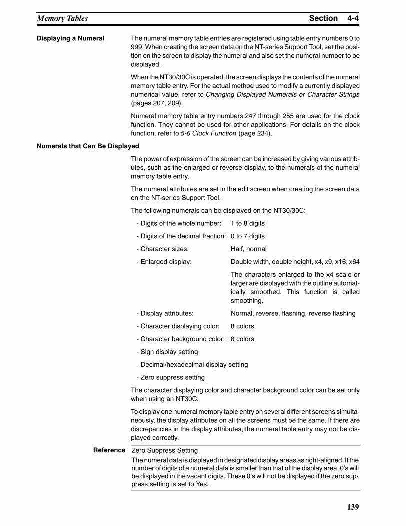
Reference
4-4SectionMemory Tables
139
Displaying a Numeral The numeral memory table entries are registered using table entry numbers 0 to999.When creating the screen data on the NT-series Support Tool, set the posi-tion on the screen to display the numeral and also set the numeral number to bedisplayed.
When theNT30/30C is operated, the screendisplays thecontents of thenumeralmemory table entry. For the actual method used to modify a currently displayednumerical value, refer to Changing Displayed Numerals or Character Strings(pages 207, 209).
Numeral memory table entry numbers 247 through 255 are used for the clockfunction. They cannot be used for other applications. For details on the clockfunction, refer to 5-6 Clock Function (page 234).
Numerals that Can Be Displayed
The power of expression of the screen can be increased by giving various attrib-utes, such as the enlarged or reverse display, to the numerals of the numeralmemory table entry.
The numeral attributes are set in the edit screen when creating the screen dataon the NT-series Support Tool.
The following numerals can be displayed on the NT30/30C:
- Digits of the whole number: 1 to 8 digits
- Digits of the decimal fraction: 0 to 7 digits
- Character sizes: Half, normal
- Enlarged display: Double width, double height, x4, x9, x16, x64
The characters enlarged to the x4 scale orlarger are displayedwith the outline automat-ically smoothed. This function is calledsmoothing.
- Display attributes: Normal, reverse, flashing, reverse flashing
- Character displaying color: 8 colors
- Character background color: 8 colors
- Sign display setting
- Decimal/hexadecimal display setting
- Zero suppress setting
The character displaying color and character background color can be set onlywhen using an NT30C.
To display one numeralmemory table entry on several different screens simulta-neously, the display attributes on all the screens must be the same. If there arediscrepancies in the display attributes, the numeral table entry may not be dis-played correctly.
Zero Suppress SettingThenumeral data is displayed indesignateddisplayareasas right-aligned. If thenumber of digits of a numeral data is smaller than that of the display area, 0’swillbe displayed in the vacant digits. These 0’s will not be displayed if the zero sup-press setting is set to Yes.

4-4SectionMemory Tables
140
4-4-3 Bit Memory TableThe bit memory table is an internal memory area for bit data.
The NT30/30C can use amaximum of 256 bit memory table entries. One bit sta-tus in the PC can be stored in a single bit memory table entry.
Functions of Bit Memory Table
There are two functions of the bit memory table.
S Screen Changeover Function
When a bit in the PC to which a bit memory table entry is assigned changesfrom 0 (OFF) to 1 (ON), the screen changes to show the screen set for that bit.
No. 1No. 2No. 3
PC000
Screen number11 displayed
Screen number 10Screen number 11Screen number 12
Bit
1 (ON)
S Alarm Function
When a bit in the PC assigned to the bit memory table entry is 1 (ON), the char-acter string memory table entry and image or library data set for it are dis-played. Smaller bit memory table entry numbers are displayed preferentiallywhenmultiple bit memory table entries have been set to the alarm list function,enabling setting the order of priority for messages displayed using the bitmemory table. For details, refer to the 4-11 Alarm List & History Display Func-tions (page 180).
No. 13
No. 14
No. 15::
PC000
1 (ON)
Character string tableentry No. 54Library data FD34
Character string tableentry No. 32
Image dataFE68
Bit
Message (character string tableentry No. 32) and image data(FE68) set for bit memory tableentry number 14
Character string tableentry No. 50Image data FE52Character string tableentry No. 32Image data FE68
Bit Memory Table Settings
When a bit memory table entry is used, it is necessary to perform the followingsettings for each table entry before creating the screen data with the NT-seriesSupport Tool. For the settings used for alarm list and history display function, re-fer to the 4-11 Alarm List & History Display Functions (page 180).
S Recording in the Alarm History
This setting is to determinewhether a changeofPCBit towhich the bitmemorytable entry is assigned is recorded in the Alarm History.
S Screen Changeover Function
This setting is to determine whether the bit memory table entry is used for thescreen changeover function.
S Character String Memory Table Entry Number
This setting is the character string memory table entry number displayed as amessage. This setting is not necessary for the screen changeover function.

4-5SectionGraphs
141
S Display Color (NT30C Only)
Color of the characters used formessage is to be set. This setting is not neces-sary when used for the screen changeover function.
S Image/Library Data
This is a setting of the code for imageor library data displayed togetherwith themessage. This setting is not necessary for the screen changeover function.
S Screen Changeover
This is a setting of a screen number displayed for the screen changeover func-tion or alarm list & history display function.
S Bit
This is a setting of a bit in the PC to which the bit memory table entry is allo-cated.
f: Possible×: Impossible
Sym-bol C Series PC Alloca-
tion CVM1/CV Series PC Alloca-tion CS1 Series PC Alloca-
tion
DM DM Area f DM Area f DM Area f
CH IR Area f CIO Area f CIO Area f
TIM Timer Area × Timer × Timer ×CNT Counter Area × Counter Area × Counter Area ×HR HR Area f -- -- HR Area ×AR AR Area f Auxiliary Area × Auxiliary Area ×LR LR Area f -- -- -- --
The Auxiliary Area of CV series PC is used exclusively for special applications inthe system, and cannot be used for other application.
When specifying the DMArea, specify the bit number (00 to 15) along with theword address.
4-5 Graphs
Thecontents of numeralmemory table entries of theNT30/30Ccanbedisplayedas graphs as well as numeral data.
Three typesofgraphcanbedisplayed:Bar graphs, trendgraphs,andbroken linegraphs.
The display data of graphs is changed by changing the contents of numeralmemory table entries.
For theactualmethodused toupdate thedata of a currently displayedgraph, seeUpgrading Graphs (page 215).Graphsettings aremadewhencreating screendata using theNT-seriesSupportTool.

4-5SectionGraphs
142
4-5-1 Bar Graph FunctionsThe bar graph function displays a value in a bar graph form as a percentage tothe specified value according to the contents of numeral memory table entries.Up to 50 bar graphs can be registered on one screen.
S Table Entry
The numeral memory table entry used used for the bar graph display is set.
The NT-series Support Tool has the direct and indirect options for the accessmethod of the numeral memory table entries. However, the NT30/30C uses thedirect method only.
The bar graph display cannot use hexadecimal numbers. If hexadecimal num-bers are set in the numeral table entry, the bar graph cannot be displayed. Usecaution not to write hexadecimal numbers except the minus sign (F) to the nu-meral table entry being accessed for the bar graph.
Bar Graph Attributes The following attributes can be set with the NT30/30C for the bar graph display:
S Graph Frame
This attribute specifies a rectangular area used to display a graph.
S Incremental Direction
The incremental direction of the bar graph can be selected from those men-tioned below.
↑ (up): The bar graph increments upward.
↓ (down):The bar graph increments downward.
← (left): The bar graph increments to the left.
→ (right):The bar graph increments to the right.
Direction:→Direction: ↑
S Graph Frame
Select whether or not the graph frame (boundary line of a graph display area)that indicates the effective display range is displayed.
← This frame is not displayed if“Graph frame: No” has beenset.
S % Data Value
Datavaluecorresponding to0%,100%, --100%canbespecified.%Data valuecan be specified by twomethods: by directly specifying a numeric value and/orby accessing a numeral memory table entry.
- Directly Specifying Method
Numeric value from 0 to 99999999 (max. 8-digit) is specified. It is necessaryto set that 0% value is more than --100% one, and 100% value bemore than0% one without fail.

4-5SectionGraphs
143
- Memory Table Access Method
Thenumeralmemory table entry number to be accessed is specified insteadof a numeric value.With thismethod specified, data canbechanged from thehost during operation.
S % Display
% Value can be displayed.
% Value can be calculated according to the following equation:
% Value = Numeral memory table entry value -- 0% Value100% Value -- 0% Value (or 0% Value -- (--100% Value))
× 100
For the font and attributes used for the numeral display, refer toNumerals thatCan Be Displayed (page 139).
S Sign Display and Display Method
Select whether or not the bar graph that indicates a value below 0% is dis-played.
To Display a Value Below 0%: Sign Display Yes
The bar graph is displayed in the range of --100% to 100%. Themiddle of thebar graph indicates 0%.
% display
0% 100%--100%
--60%
Not to Display a Value Below 0%: Sign display No
The bar graph is displayed in the range of 0% to 100%. The end of the bargraph indicates 0%. Values below 0% are indicated as 0%.
% display
0% 100%
60%
S Differences in the Bar Graph Display Method According to the % Values
The bar graph display method varies according to the % value range.
(1) When the % value is in the minus range
The display varies as follows according to the sign display setting:
Sign display No: Displayed as 0%.Sign display Yes: Displayed in the minus range.
(2) When the absolute value of the % value is in the range of 100% to 999%
The % value is displayed as it is.
Sign display No: The display will be as mentioned below according tothe graph frame setting.

4-5SectionGraphs
144
When the frame is displayed:
% display
0% 100%
999%
Graph width: 8 dots↔
When the frame is not displayed:
% display
0% 100%
999%
Graph width: 8 dots↔
1-dot-wide space
Sign display Yes: A value below --100% will be displayed in the minusdirection as shown above.
(3) When the absolute value of the % value is above 1000%
The bar graph will be displayed the same as (2) above.
The % value is displayed as follows according to the sign display setting:
Sign display No: :::%Sign display Yes: ::::%
S Color Display (NT30C Only)
Color of a graph to be displayed can be specified. For background of a graph,screen background color is displayed.
Graph frame (in case of a graph frame): 8 colors+ direction display area: 8 colors-- direction display area: 8 colors
4-5-2 Trend Graph SettingA trend graph displays the displacement with the lapse of time as a locus whilemonitoring (sampling) the numeral memory table entry value periodically. Astime goes by, the displacement varies as shown below.
Example of Normal Type that Increases Rightward With a Sign Displayed
For a trend graph, a single graph frame can be shown on a screen and a maxi-mum of 50 graphs can be registered in the graph frame.
S Table Entry
This is the same as for bar graphs. See page 142.
Although it is possible to select either direct or indirect as the access methodwith the NT-series Support Tool, only the direct setting is used by theNT30/30C.
It is not possible to use hexadecimal values for bar graphs. If hexadecimal val-ues are specified in numeral memory table entries for graph values, the graph

4-5SectionGraphs
145
will not be displayed. The letter Fmay be used to indicate negative values, butmake sure that no hexadecimal values are written.
It is not possible to use hexadecimal values for trend graphs. If hexadecimalvalues are specified in numeral memory table entries for graph values, thegraph will not be displayed. The letter F may be used to indicate negative val-ues, but make sure that no hexadecimal values are written.
Trend Graph Attributes When using an NT30/30C, the following attributes can be used when displayingtrend graphs.
S Graph Frame
This attribute specifies a rectangular area used to display a graph. Range ofthis area is a maximum of 320 dots in length by 240 dots in width.
The following setting can be performed for a graph frame.
- Frame Display
With Frame Display specified, 1-dot width frame line is displayed outside ofthe frame area. With the NT30C, color of a frame line can be selected out ofeight colors.
- Background Color in a Frame (NT30C Only): 8 Colors
Separate background color can be specified for positive and negative valuedisplay area.
S Displaying Method
A graph displaying method can be selected out of two types: normal type andpen recorder type.
- Normal Type
As timegoesby, the latest datadisplaypositionmoves toward thedirectionofincrease. When the displacement increases to the right, a graph varies asshownbelow.Whenapolygonal line reaches theendof a screen, it is clearedonce and the NT30/30C starts drawing a polygonal line again from the first.
At the second time andthereafter, the NT30/30Cdraws a graph from thelast data to the latestdata.
Direction of increase : Latest data
At first theNT30/30C draws agraph from 0 to thelatest data.
: Latest data : Latest data : Latest data : Latest data
- Pen Recorder Type
The latest data is always displayed at the end of the screen. As time goes by,the graph already displayed moves in the direction of increase. When agraph increases to the right, it varies as shown in the figure below.
Data is clearedfrom old one.
Direction of increase : Latest data
At first theNT30/30C draws agraph from 0 to thelatest data.
: Latest data : Latest data : Latest data : Latest data

4-5SectionGraphs
146
S Direction of Movement
The normal type can select the direction that the display position of the latestdata moves with the lapse of time. The pen recorder type can select the direc-tion that entire graph moves.
DownwardRightward Upward Leftward100% 100%
100% 100%
100% position is determined in accordance with the direction of scroll. 100%position falls to the right when a graph scrolls longitudinally and at the upperside when a graph scrolls laterally.
S Sign Representation
This attribute can specify whether or not a numeric value less than 0% value isdisplayed.
To Display a Value Below 0%: Sign Display Yes
The trend graph is displayed in the range of --100% to 100%. In this case, 0%position of a graph falls the center of a graph display area.
100%
--100%
100%
the latest data: --50%
the latest data: 80%
Not to Display a Value Below 0%: Sign Display No
The trendgraph is displayed in the rangeof 0% to 100%. 0%position is at theend of a graph. All values less than 0% are displayed as 0%.
100%
100%
the latest data: 80%
the latest data: --120%
S Drawing Width
Drawingwidth (direction of increase)must be specified from the previous datato the following data in the range of 1 to 320 dots. If a valuemore than the graphdisplaying frame is specified, a graph will not be displayed.
Direction of increase
Drawing width

Reference
4-5SectionGraphs
147
S Sampling Period
Sampling period is the time interval applied when the NT30/30C samples anddisplays the numeral memory table value and is specified in the range of 1 to65535 in increments of 0.1 second.
Actual drawing timing varies depending on the operating conditions. This doesnot accurately coincide with the time interval specified.
S % Data Value
The same is also true as the bar graph. Refer to page 142.
S Graph Line Type
This attribute specifies a graph line type among those as shown below. Linecolor can be selected out of eight colors. A graph width is fixed at onedot.
Solid line
Broken line
1-dot chain line
2-dot chain line
S % Representation
The same is also true as the bar graph. Refer to page 142.
S Differences in the Bar Graph Display Method According to the % Values
The bar graph display method varies according to the % value range.
(1) When the % value is in the minus range
The display varies as follows according to the sign display setting:
Sign display No: Displayed as 0%.
Sign display Yes: Displayed in the minus range.
(2) When the absolute value of the % value is in the range of 100% to 999%
A graph is not displayed in this range of %. Only a part of % value within thegraph frame is displayed. A % value is displayed as it is.
the latest data: --300%
the latest data: 50%
100%
--100%
100%
(3) When an absolute value of % is equal to or greater than 1000%
A value is displayed in a graph in the sameway as (2) at the% display posi-tion depending on the presence of a sign as follows:
With a sign not displayed:::: %
With a sign displayed::::: %
S When the Graph Width Is Not an Integral Multiple of the Drawing Width
In the normal type, when a graph is over the graph frame next time, theNT30/30C draws a graph of the latest data at the end of the frame.

Reference
4-5SectionGraphs
148
Example: In case the graph width 100-dot and the drawing width 30-dot
Drawn at the end
100-dot
0 30 60 90 30 60 90 30 60 90
10
(1) (1) (1)(2) (2)
(3)
If a graph is duplicated by drawingmultiple graph lines of the same% value, it isoverwritten and displayed in the order of setting. Similarly, when 0% value con-tinues in a graph with a sign displayed, a graph line is overwritten and displayedwith respect to the graph frame indicating 0%.
4-5-3 Broken Line Graph SettingAbroken line graph displaysmultiple present value of numeralmemory table en-tries by a single polygonal line. This allows variation of continuous values of thenumeral memory table entries to be seen at a time.
Example displaying 11 numeralmemory table entry values withsigns
100%
--100%
100%
For a broken line graph, a single graph frame can be shown on a screen and amaximum of 256 graphs can be registered in the graph frame. A single brokenline can display a maximum of 512 numeral memory table entries. However, themaximumnumber of numeralmemory table entries that can bedisplayed ononescreen is also 512.
S Table Entries (First Table Entry Number) (Line Attribute)
Specifies the first memory table entry number of the series of memory tableentries to be accessed for the line graph.
Although it is possible to select either direct or indirect as the accessmethodwiththe NT-series Support Tool, only the direct setting is used by the NT30/30C.
It is not possible to use hexadecimal values for broken line graphs. If hexadeci-mal values are specified in numeral memory table entries for the graph values,the graphwill not be displayed. The letter Fmay be used to indicate negative val-ues, but make sure that no hexadecimal values are written.
Broken Line Graph Attributes
When using an NT30/30C, the following attributes can be used when displayingbroken line graphs.
S Graph Frame (Position, Size)
This attribute specifies a rectangular area used to display a graph. Range ofthis area is a maximum of 320 dots in length by 240 dots in width.
The following setting can be performed for a graph frame.
- Frame Display
With the FrameDisplay specified, 1-dot width frame line is displayed outsideof the frame area.With the NT30C, Color of a frame line can be selected outof eight colors.
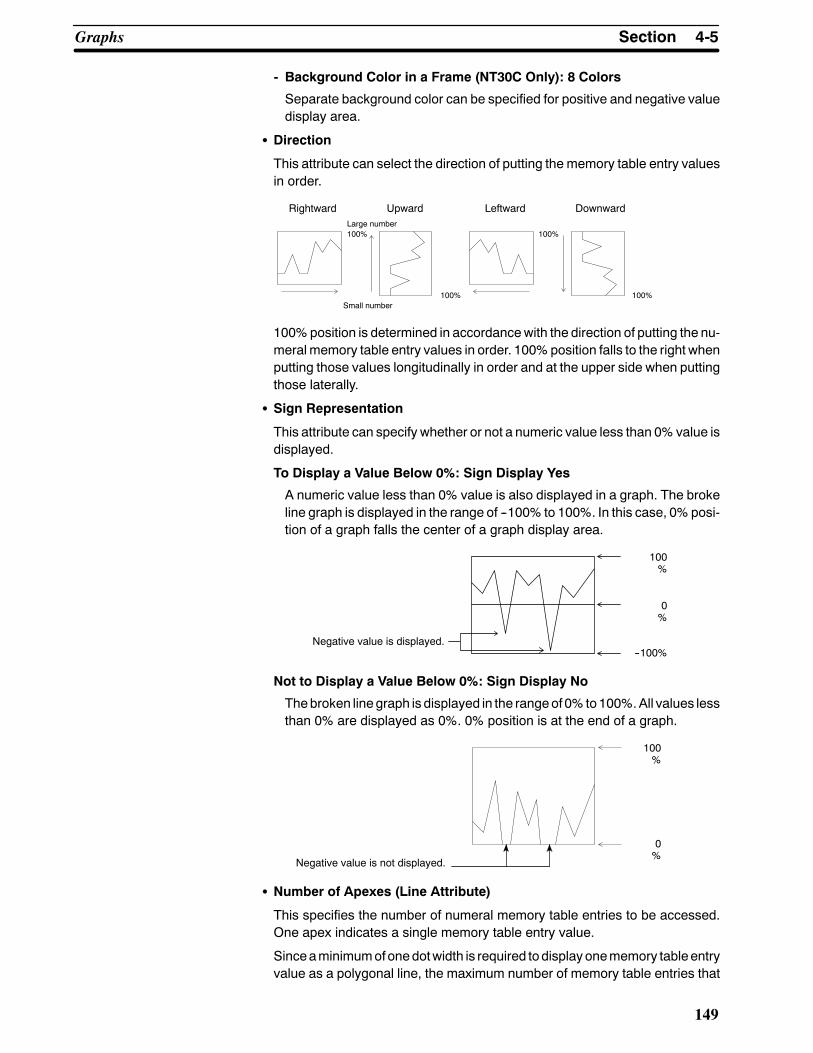
4-5SectionGraphs
149
- Background Color in a Frame (NT30C Only): 8 Colors
Separate background color can be specified for positive and negative valuedisplay area.
S Direction
This attribute can select the direction of putting the memory table entry valuesin order.
DownwardRightward Upward Leftward
100% 100%
100% 100%
Large number
Small number
100%position is determined in accordancewith the direction of putting the nu-meral memory table entry values in order. 100%position falls to the right whenputting those values longitudinally in order and at the upper side when puttingthose laterally.
S Sign Representation
This attribute can specify whether or not a numeric value less than 0% value isdisplayed.
To Display a Value Below 0%: Sign Display Yes
A numeric value less than 0% value is also displayed in a graph. The brokeline graph is displayed in the range of --100% to 100%. In this case, 0%posi-tion of a graph falls the center of a graph display area.
Negative value is displayed.
100%
--100%
100%
Not to Display a Value Below 0%: Sign Display No
Thebroken linegraph is displayed in the rangeof 0% to100%.All values lessthan 0% are displayed as 0%. 0% position is at the end of a graph.
Negative value is not displayed.
100%
100%
S Number of Apexes (Line Attribute)
This specifies the number of numeral memory table entries to be accessed.One apex indicates a single memory table entry value.
Sinceaminimumofonedotwidth is required todisplay onememory tableentryvalue as a polygonal line, the maximum number of memory table entries that

4-5SectionGraphs
150
can be references for the graph frame width is determined by the followingequation.
Graph frame width (number of dots)≧ Number of memory table entries
S % Data Value (Line Attribute)
This attribute specifies the% data value at every polygonal line. For the speci-fying method, the same is also true as the bar graph. Refer to page 142.
“% representation” cannot be performed for the polygon.
S Graph Line Type (Line Attribute)
This attribute specifies a graph line type among those as shown below. WithNT30C, line color can be selected out of eight colors. A graph width is fixed atonedot.
Solid line
Broken line
1-dot chain line
2-dot chain line
S Differences when A Broken Line Graph Is Displayed Using PercentageValues
When % value is in the following range, the graph displaying method is re-stricted as follows:
(1) In case of negative % value
A graph is displayed differently depending on the sign representation.Without sign representation: Displayed in the same manner as 0%.With sign representation: A graph is displayed in the negative direc-tion.
(2) When an absolute value of % is from 100% to 999%
A graph is not displayed in this range of %. Only a part of % value within thegraph frame is displayed.
The values outside of this range are not displayed.
100%
--100%
100%
Values outside the range are not displayed.
(3) When an absolute value of % is equal to or greater than 1000%
A value is not displayed in a graph in the same way as (2).

Reference
4-6SectionLamps
151
S If a graph is duplicated by drawingmultiple graph lines of the same% value, itis overwritten and displayed in the order of setting. At this time, since the partthat the linesareduplicated is displayedbyuseof thosecolorsof theExclusiveORdisplay (Refer topage124), the line typeand line color aredisplayeddiffer-ently than that specified.
S Since a graph line is overwritten with respect to the graph framewhen 0%val-ue continues in a graph with a sign displayed, line type and line color are dis-played differently than that specified.
S The interval between apexes for broken line graphs can be changed freelyusing Interval Setting under Line Property. (With DOS versions of the NT-se-riesSupport Tool, the interval betweenapexes is fixedat the same interval andcan be changed when the broken line graph is corrected.
4-6 LampsA lamp is a graphic area capable of changing the displaying state according to acommand from the PC. There are two kinds of lamps: Normal lamps that changethedisplaying state (OFF,ON, flashing) of a graphic fixedly displayedand image/library lamps that display separate graphics in OFF and ON states. Lamps areset when creating screen data on the NT-series Support Tool.
Amaximum of 256 lamps can be set on a screen, and 1,024 lamps can be regis-tered in a screen data file.
Contents of the setting differs depending on the lamp type (normal lamp orimage/library lamp).
For theactualmethodused tomodify a currently displayed lamp, seeTurningONand OFF Lamps (page 216).
4-6-1 Normal Lamp FunctionsNormal Lamp is used to change the display state (reverse flashing, erase) of agraphic fixedly displayed according to an instruction (bit ON/OFF) from the PC.
PC
OFF state ON state
Lamp Attributes
The following attributes can be set for the normal lamps.
S Shape
Any shape can be selected out of the following four kinds of shapes. Size canbe specified freely.
Square Circle FanPolygon

4-6SectionLamps
152
S External Frame
This attribute can be set to determine whether or not a boundary line of theLamp is displayed.When an external frame is set to not be displayed, only theguide display characters of the lampare displayedwhen the lamp is notON (orflashing). When the guide display character is not set, nothing is displayed.
S ON/Flashing
When lamp isONbyan instruction from thePC, its displaying state canbespe-cified out of ON (inverse illumination) or Flashing (inverse flashing).
S Color Display (NT30C Only)
External frame color (in case of color display): 8 colors
OFF color: 8 colors or transparent
ON/Flashing color: 8 colors
A part of external frame may be lost depending on a combination of externalframe color of the normal lamp and OFF color or ON/Flashing color. This iscaused by the properties of the color LCD and does not indicate failure ofequipment. When part of the external frame is lost, change a combination ofcolors.
S Guide Display
Guide display character can be attached to the lamp. Attributes of the guidedisplay character are the same as that of character display. Refer to Charac-ters and Figures that can be Displayed (page 137).
S When a Memory Table Display Is Overlapped with a Normal Lamp
The guide display character of the normal lamp is a fixed character string. Inorder to change the guide display of the normal lamp according to the circum-stances, display the display area of the numeralmemory table entry or charac-ter stringmemory table entry in conjunctionwith illumination of lamp.However,depending on a timing of ON of normal lamp and memory table entry update,the result of indicationdiffers as shown in theexamples below.Be carefulwhencreating a control program.
Example 1: When the normal lamp is turned ON after updating the memorytable entry
The charactersare displayed inwhite againstdark background.
Lamp OFF
LAMP Character string memorytable entry display area
Memory tableentry update
Lamp OFF Lamp ON
PTOMRON PT
Lamp ON

4-6SectionLamps
153
Example 2: When thememory table entry is updatedwhile normal lamp isON
The memory tableentry display areain the lamp duringillumination is over-written.
The charactersare displayed inwhite againstdark background.
Lamp OFF
Lamp Character string memorytable entry display area
Memory tableentry update
Lamp ON Lamp ON
OMRON PTOMRON
Lamp ON
S Frame Display and ON/Flashing
ON/Flashing operations differ depending on the presence of the frame displayof the normal lamp.
When the frame is displayed, only an area within the frame is ON or flashing.When the frame is not displayed, an area is ON or flashing together with theframe.
Unlit
Flash
LitUnlit
Flash
Lit
When the Frame Is Displayed When the Frame Is Not Displayed
Only within the frameis flashing.
The frame is alsoflashing concurrently.
S Combined display of normal lamp
Withmultiple lampsof the samenumber (or the samebit) registered, the lampscombined as shown below can be ON simultaneously.Display Example
The same number (or bit) is specified for the lamps L1 through L5.
L1L2L3 L4 L5
L1 L2 L3L4L5
4-6-2 Image/Library Lamp FunctionThe image/library lampdisplays adifferent imageor library data anddisplays it ata different position according to a command (bit ON/OFF) from the PC.
PC
OFF state ON state
Position andgraphic to bedisplayed can bevaried.
ON
For an image/library lamp, the presence of an external frame, ON/flashing, colordisplay, guide display, and so forth, cannot be specified.

Caution
4-7SectionTouch Switches
154
However, since theattributes of every display factorswhen registering the librarydata are displayed as they are, a range of application will be widened further.
Image/Library Lamp Attributes
The following attributes can be set to an image/library lamp.
S Lamp Codes
Graphics to be displayed during ON and OFF are specified by the library orimage data codes.
S Display Position
Positions to be displayed during ON and OFF are specified.
4-7 Touch SwitchesTheNT30/30Chas a functionwhereby input operations can be performedby us-ing touch panels displayed on the screen.NT30/30C screens canbe switchedorbit information can be sent to the PC by pressing (lightly touching) the touchswitches on the panel.
The touch switches canalso bemade to light up (or flash) andgoOFF like lamps.
Touch switches are set when creating the screen data on the NT-series SupportTool.
The following explanation covers the typesof touch switch that canbedisplayed,and functions other than that for notification to the PC.
For the actual method used to notify touch switch statuses to a PC, see TouchSwitch Status (page 220).
For the actual method used to access touch switch statuses at the PC, seeNoti-fying the PC that a Switch Has Been Pressed (page 220).
S Do not use input functions such as PT touch switches for applications wheredanger to human life or serious property damage is possible or for emergencyswitch applications.
S Press touch switches with a force of no greater than 30 N.Applying higher force may cause glass to break, possibly resulting in injuriesand prevent operation.
S Do not press touch switches carelessly while the backlight is OFF or whilenothing is displayed on the screen.Otherwise the systemmay operate unpre-dictably.Only press touch switches after confirming system safety.

Correct use
4-7SectionTouch Switches
155
S If touch switches are pressed in rapid succession, their inputs may not besuccessfully received. Confirm that the input of a touch switch has beensuccessfully received before moving on to the next operation.
S Note on pressing 3 touch switchesWhenmultiple touch are set in positions that form a row and three of thesetouch switches are pressed at the same time, amalfunction occurs due tocharacteristics of the touch switch configuration.Be careful how you position touch switches when setting them.Example 1: Touch switches are created at positions A and B and at theirvertical/horizontal intersection points C or D
S When switches A, B, and C are turnedON simultaneously, switch D is also re-garded as having come ON due to thetouch switch configuration.
S When switches A, B, and D are turnedON simultaneously, switch C is also re-garded as having comeONat the sametime.Small touch switch frame
A
D
C
B
4-7-1 Functions of Touch SwitchesTouch switches are created using rectangular elements shown below. A touchswitch can comprise more than one touch switch element. Up to 192 touchswitches can be registered on one screen.
STOP
PC
20 dots (7.2 mm)
20 dots (7.2 mm)
Multiple touch switch elementsmake up a single touch switch.
When the touch switch is pressed, the touchswitch status is sent to the PC.
16 horizontally x 12 vertically
S Functions of Touch Switches
Touch switches can have the following functions:
• PC notification function (page 220)• Screen switch (stand-alone) function (page 157)• Input key function* (page 159)• Copy key function (page 160)• Cursor moving key function (page 160)• Screen print function (page 160)
* The “input key function” is a general term for the 3 functions characterstring (character key) input function,” “pop-up window/keyboard (windowkey) function,” and “control code input (control key) function” that are dis-played on the NT-series Support Tool.

4-7SectionTouch Switches
156
Touch Switch Attributes The following attributes can be set for the touch switches.
S Display Frame
Adisplay frame of the touch switch can be specified by the following twometh-ods.
- Fixed-shape Display Frame
This is a frame displaying an area of display frame type that acts as TouchSwitch. There are four kinds of display frames as shown in the table below:Standard, Solid 1, Solid 2, No Display Frame.
When NoDisplay Frame is selected, only the label is displayed (or nothing ifno label is specified) unless an ON (or flash) instruction is sent from the PC,or the touch switch is pressed.
Display Frame Type Switch OFF Switch ON
Standard
Solid 1
Solid 2
No display frame
- Free-shape Display Frame
This is a display frame capable of freely setting the display position andshape irrespective of Touch Switch area. A shape to be specified can be se-lected out of Square, Circle, Polygon, and Fan.
For example, free-shape display frame can be used in the followingmanner.
When this positionis pressed
Touch Switch area
Display frame
Shown in reverse video
Example: Setting a display frame inside the touch switch area
When this positionis pressed
Touch Switch area
Display frame
Shown in reverse video
Example: Setting a display frame outside the touch switch area
S Reverse Video Entry
This attribute can specify the Touch Switch so as to be shown in reverse videowhen it is touched and operated.
S Guide Display
Labels can be assigned to touch switches. When the touch switch is ON, thelabel is displayed in reverse video in the case of an NT30 and in the exclusive

4-7SectionTouch Switches
157
OR color (see page 124) in the case of the NT30C. Attributes of guide displaycharacters are in the same way as character display. Refer to Characters andFigures that can be Displayed (page 137).
S ON/Flashing
This attribute can specify whether or not the Touch Switch is allowed to be ONor flashingwhen the TouchSwitch is ONor flashing according to an instructionfrom the PC.
S Color Display (NT30C Only)
External frame color (when displayed): 8 colors
OFF color: 8 colors or transparency
ON/Flashing, entry color: 8 colors
4-7-2 Stand Alone Function
TheNT30/30Ccanswitchover thescreenonly by operating the switcheswithoutinstructions from the PC.
Whenscreendata is createdwith theNT-seriesSupport Tool, the screennumberof a screen to be switched over is assigned to the input terminal of the touchswitch. When the touch switch is pressed during operation, the screen of thenumber specified is displayed.At this time, the screennumber just switchedoveris also notified to the PC.
Depending on the screen number allocated to it, a touch switch can be made toperform one of two functions:
- When a Screen Number in the Range 1 to 2000 Is Specified:
Pressing the touch switches causes the display to switch to the screen withthe specified number.
- When Screen Number 0 Is Specified:
The touch switch functions as the screen switchover return key. Setting thiskey allows you to return to the screen that was displayed immediately beforethe current screen.
Screen Number in the Range 1 to 2000 Set
When the touchswitch 1 is pressedTo next screen
Screen number 5 is set to the touch switch 1
Screen number 5

4-7SectionTouch Switches
158
Screen Number in the Range 0 Set
Touch switch is pressed
Previous screenMenu Screen
Operation 1
Operation 2
Menu Screen
Operation 1
Operation 2
Screen switchoverS Instructed by the PCS Screen switchover key
Screen number 0 is setto the touch switch 1.
Only a touchswitch canhave thescreenswitchover return key function. If displayof screen number 0 is specified from the PC, the screen will go blank.
The number of screens that can be returned using the screen switchover returnkey is amaximum of 32 screens. However, it is assumed that the screen switch-over return key has been set to all screens to be returned.

4-7SectionTouch Switches
159
4-7-3 Input Key FunctionThis is a function that allows touch switches to be used for input and is mainlyusedwhen using numeral/character string setting functions. Input keys are clas-sified into the following three types:
Character keys (character string input function):
Used to input character strings when using a character--string setting func-tion. For details, see 4-9 Character String Setting (page 171).
Window keys (pop-up window/keyboard function):
Used to open and close windows when using the pop-up window function.Alsoused toswitchbetweenkeyboardswhenusingcharacter--stringsettingfunctions. For details, see 4-9 Character String Setting (page 171) or 4-10Pop-Up Window Function (page 173).
Control keys (control code input function):
Used for functions providedby the system, suchas thenumeric key functionusedwith numeral setting functions, the system key functions providedwithprevious PTmodels, and special control functions. For details, see the nextsection Functions of Control Keys.
Functions of Control Keys The touch switch control keys have the following functions:
Key Function
0 to 9, A to F Used to input numerical values
CLR Clears input numerical values and character strings
Assigns the opposite sign to input numerical values
. Used to input a decimal point
HOME Used to move to the input field at the top left of the screen
↑, ↓,←,→ Used to move to the next input field
system key (confirms character input without shifting to another input field)
system key (stops the buzzer)
, and system keys (screen switching of continuous screens, shifting to input fields)
MENU System keys + + (system menu display)
CA Used to cancel input (Cancel)
BS Deletes the numeral or character immediately preceding the input cursor
DEL Deletes the numeral or character at the input cursor location
A," Used to shift the input cursor
ENT Confirms input of a character (after confirmation, the cursor shifts to the next input field)
Alarm list/history display page scrolling
Y,B Alarm list/history line scrolling

4-7SectionTouch Switches
160
4-7-4 COPY Key FunctionWhen the Touch Switch is pressed, values or codes (constant) in the memorytable entry input columnare copied into othermemory table entry or thenumeral/character string setting input column (Refer to4-8NumeralSettingand4-9Char-acter String Setting). TheCOPY key is useful to set the numeral/character stringdisplay to its initial state and to enter the same value (initial value, etc.) into themultiple numeral/character string setting input column.
000001234567890
00000Counter
COPY key
Numeric value memory table entry00000
Copied
Code
Example: COPY key used as a RESET key for the counter
Copy source (memory table entry or code) and copy destination (memory tableentry or numeral/character string setting input column) are specified.
4-7-5 Cursor Moving Key FunctionThis is a Touch Switch to select the numeric value setting input column (ten-keytype) and the character string setting input columnwhenenteringdata.When theTouch Switch is pressed, a cursor (display frame) is moved to the numeral/char-acter string setting input column specified to be ready for input operation (Referto 4-8 Numeral Setting and 4-9 Character String Setting). The numeric value/character string setting input column is automatically produced with the NT-se-ries Support Tool. A pop-up window open function can also be set for the sametouch switch.
4-7-6 SCREEN PRINT Key FunctionWhen the TouchSwitch is pressed, a screen hard copy (screen image) is printedby a printer connected to the NT30/30C.
Two kinds of keys can be set: START key that starts the printing operation andCANCEL key that cancels the printing operation.
Even when the screen hard copy is being carried out, the NT30/30C continuesoperation.
When this key is pressed, screen hard
copy is canceled.
START key CANCEL key
Screen hard copy START key
Screen hard copy CANCEL key
+10 +1
--10 --1
When this key is pressed, screen hard copy is started.
[Temperature adjustment]
Current temp.: 20_CSet temp.: 20_C

Caution
Reference
4-8SectionNumeral Setting
161
4-8 Numeral SettingThe numeral setting is a function to enter the numeral values on the screen. Thenumeral setting allows the numeral value to be entered directly from the touchswitch or B7A Unit into a numeral memory table entry to be displayed on thescreen and further to be sent to the PC.
The following is a guide to the numeral setting function, a guide to themethod forcreating the numeric keys required for numeral settings on the screen, and anexplanation of how to use numeric keys during operations.
Numeral setting screens cannot be registered as child screens of continuousscreens.
With overlapping screens, only one screen can be set as a numeral settingscreen.
For the actualmethod used to notify the PC of input numerical values, seeNotifi-cation of Numbers to the PC (page 224).
The numeral setting is carried out when a screen is created with the NT-seriesSupport Tool.
Ensure that therewill be noadverseeffects on the systembefore changingmon-itor data.
4-8-1 Numeral Setting FunctionsThe numeral setting has the following functions.
Basic Operation The numeral setting operation is as follows:
(1) A numeral value is entered from the touch panel or B7A Unit.
(2) The numeral value entered is displayed in the numeral setting area on ascreen.
(3) When the numeral value entered is confirmed, it is written into the numeralmemory table entry and simultaneously sent to the host.
PC12341234
Numeral setting input field
Touch Switch Enter
B7A Unit
Enter
Writing
Numeral memory table entry
Notifying
NT30/30C
It is possible to disable input to a numeral setting input field by using a systemcontrol (PT Status Control Area) operation (see page 239).
Numerical Values that Can Be Input and Attributes that Can Be Set
Numeral values up to 8-digit (up to 7-digit for negative numbers) can be enteredin decimal and hexadecimal notation.
S Entry of Decimal Number
When the display attribute is set to decimal number display, a numeral valuecan be entered in decimal.

Correct use
4-8SectionNumeral Setting
162
- Range of Numeral Values
Range of numeral values that can be entered differs depending on a sign.
With a sign not displayed: 0 to 99999999 (8-digit)
With a sign displayed: --9999999 to+99999999 (7-digit negativenum-ber, 8-digit positive number)
For a thumbwheel type, numeric values are up to 7-digit for both positive andnegative numbers with signs displayed.
- Decimal Point
A maximum of 7 digits can be entered to the right of the decimal point.
S Entry of Hexadecimal Number
When thedisplayattribute is set to hexadecimalnumberdisplay, anumeral val-ue can be entered in hexadecimal.
- Range of Numeral Values
Range of numeral values that can be entered is from 0 to FFFFFFFF (8-dig-it).
S Attributes That Can Be Set
The attributes that can be set for numerical values displayed in input fields arethe same as those for numeral displays. SeeNumerals that can be Displayed(page 139).
Checking the Upper/Lower Limit
When the upper limit and lower limit of the input numeral values have been set,erroneous numeral values outside of the range can be prevented from beingstored in the numeral memory table entry or notified to the PC.
When the numeral values entered are confirmed, upper/lower limits arechecked.
When the numeral values entered are confirmed, upper/lower limits arechecked.Otherwise the system may operate unpredictably.
4-8-2 Types of Numeral SettingThere are two kinds of numeral setting: numeric keys and thumbwheels. Thoughthe basic functions are the same, screen display and inputtingmethods differ be-tween two types.
A maximum of 50 input fields (combined total for both numeric keys and thumb-wheels) can be registered on one screen.
Numeric Keys Whenany numeral value is entered by the numeric key (character key) assignedto the touch switch or B7A Unit, a numeral value just entered is displayed on ascreen.When theRETURNkey is pressed after an input operation is completed,the numeral value entered is written into the numeral memory table entry andthen notified to the host.
When there are multiple numeral setting input columns, a numeral setting inputcolumn for input operation is also selected by the numeric key.
Touse the numeric key type, it is necessary to create not only the numeral settinginput column on a screen but also the numeric key for input operation (Refer topage 164).

4-8SectionNumeral Setting
163
Using a Touch Panel
PC1234
1 2 3
4 5 6
7 8 9
1234
When the key is pressed, an input value iswritten in the numeral memory table entry andsimultaneously notified to the host.
Displayed in the numeralsetting input column
NT30/30C
Enter
A numeral value is entered using thenumeric key in the screen.
Writing
Numeral memory tableentry
Notifying
Using a B7A Unit
Displayed in the numeralsetting input column
PC12341234
Enter
B7A Unit
Writing
Numeral memory table entry
Notifying
NT30/30C
When the key is pressed, an input value iswritten in the numeral memory table entry andsimultaneously notified to the PC.
Thumbwheels By means of touch switches that can be increased/decreased every digit of nu-meral value, a numeral value can be entered from the numeral setting input co-lumn. Every time a numeral value displayed is changed, the numeral value dis-played iswritten into thenumeralmemory tableentryandsimultaneouslynotifiedto the PC.
Therefore, the thumbwheel type can perform an entry of numeral value only bycreating the numeral setting input column on a screen.
Each time the -- key is touched, a numeralvalue decreases by 1.
PC1234
Writing
Numeral memory table entry
Notifying
NT30/30C
Each time the + or -- key is touched, an inputvalue is written into the numeral memory tableentry and simultaneously notified to the PC.
Each time the + key is touched, anumeral value increases by 1.
1 3+ + +2 4
+
-- -- -- --

Reference
4-8SectionNumeral Setting
164
4-8-3 Numeric Key Creation
In order to use the numeric key type numeral setting, it is necessary to create notonly the numeral setting input column on a screen but also a numeric key for per-forming an input operation.
Screen Attribute Setting A numeric key type can be selected by setting a screen attribute.
The System Keypad (Numeral Setting) of the screen attributes is specified toSystem (System Keypad set to ON) or User (System Keypad set to OFF).
S Screen when System Is Specified
When a numeral setting input field is created, numeric keys are automaticallydisplayed.
Numeric key display position and arrangement are fixed. In this screen, onlythe type of numeric key (system key) in the following page can be used.
Tank A5000Tank C2662Tank E0800
Tank B3000Tank D1204Tank F0990
7 8 9 CLR
4 5 6
1 2 3
0 . +/--
S Screen when User Is Specified
Display position and arrangement of the numeric key can be set freely by as-signing to the touch switch (Refer to page 165).
Tank A5000Tank C2662Tank E0800
Tank B3000Tank D1204Tank F0990
7 8 9
CLR
4 5 6
1 2 3
0 .
±
HOME
Numeric keys are created using the control keys (touch switches with the con-trol code input function). Also, normal size characters of 0 to 9andA toFcanbeused as numeric keyswith the character keys (touch switcheswith the charac-ter string input function).
With the DOS version of the NT-series Support Tool, even when the NumeralSetting of the screen attribute is User, there is still a function for automaticallycreating system numeric keys. The Windows version, however, does not havethis function.

4-8SectionNumeral Setting
165
Allocation of Numeric Keys
Numeric keys can be allocated to the touch switches or B7A Unit.
S Allocation to Touch Switches
When the touch switches are used as numeric keys, the numeric keys allo-cated are specified when creating the touch switches.
For numeral settings, the following numeric keys (system keys) can be used.
For creation of the touch switches, refer to 4-7 Touch Switches (page 154).
Numeric key Numeric key Numeric key(system key)
0 A "
1 B #
2 C z
3 D !
4 E
5 F
6 CLR
7 +/--
8 . MENU
9 HOME
* “MENU” means the system menu display.
When a numeral setting screen is displayed, no notification will bemade to thePC if touch switches for which numeric key and system key allocations havebeen made are pressed.
S Allocation to the B7A Unit
A numeric key is allocated to each input from the B7AUnit. For details, refer tothe 4-12 Operation of B7A Unit (page 185).
In the numeral setting screen, entry from the B7AUnit allocated to the numerickeys and system keys will not be notified to the PC.
4-8-4 How to Use Numeric Key Settings
In order to enter the numeral values using numeric keys, the numeral setting in-put column subject to entry must be specified to be ready for input operation be-fore entering the numeral values using the numeric key.
Specifying the Numeral Setting Input Column to Be Entered
The numeral setting input column to be entered is specified by either numerickey, systemkey, or touch switch (numeral/character string setting cursormovingkey).
The frame (cursor) around the specified numeral setting input column and thecursor attributes can be specified.
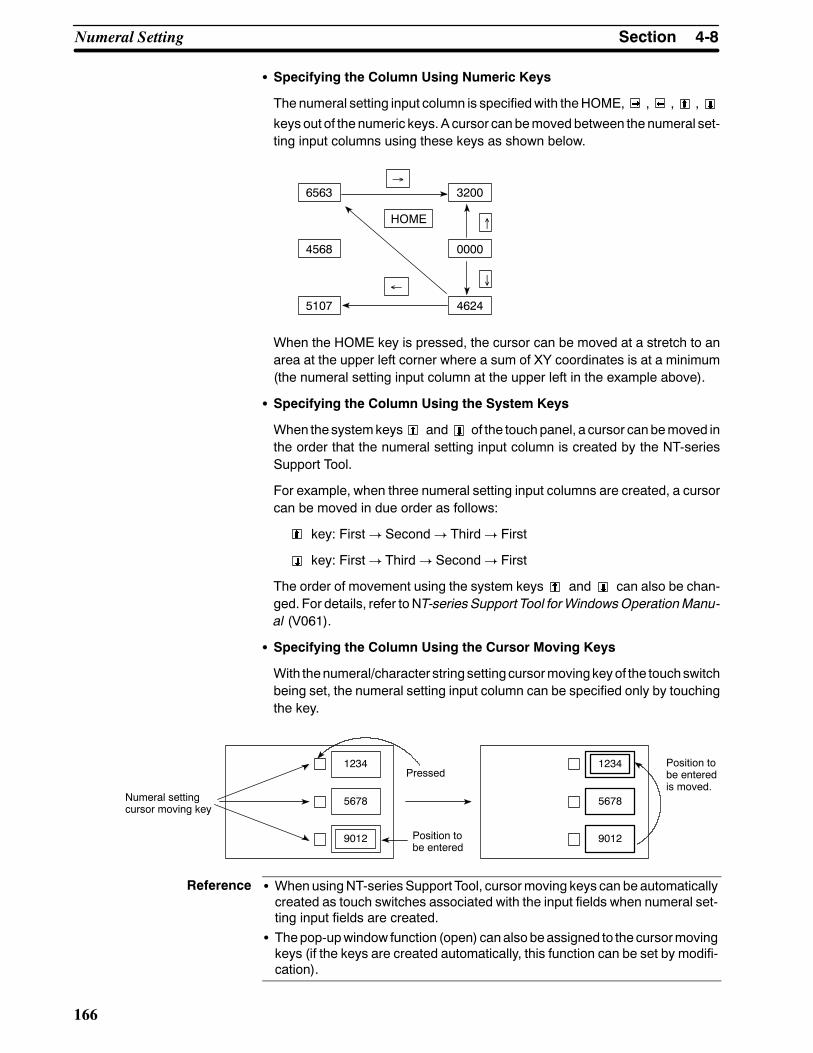
Reference
4-8SectionNumeral Setting
166
S Specifying the Column Using Numeric Keys
The numeral setting input column is specifiedwith theHOME, , , ,
keys out of the numeric keys. A cursor canbemoved between the numeral set-ting input columns using these keys as shown below.
6563
4568
5107
3200
0000
4624
HOME
←
↑
↓
→
When the HOME key is pressed, the cursor can be moved at a stretch to anarea at the upper left corner where a sum of XY coordinates is at a minimum(the numeral setting input column at the upper left in the example above).
S Specifying the Column Using the System Keys
When the systemkeys and of the touchpanel, a cursor canbemoved inthe order that the numeral setting input column is created by the NT-seriesSupport Tool.
For example, when three numeral setting input columns are created, a cursorcan be moved in due order as follows:
key: First! Second! Third! First
key: First! Third! Second! First
The order of movement using the system keys and can also be chan-ged. For details, refer toNT-series Support Tool forWindowsOperationManu-al (V061).
S Specifying the Column Using the Cursor Moving Keys
With thenumeral/character string settingcursormovingkeyof the touchswitchbeing set, the numeral setting input column can be specified only by touchingthe key.
Position tobe enteredis moved.
1234
5678
9012
Numeral settingcursor moving key
Pressed1234
5678
9012Position tobe entered
S WhenusingNT-series Support Tool, cursormoving keys can be automaticallycreated as touch switches associated with the input fields when numeral set-ting input fields are created.
S Thepop-upwindow function (open) canalsobeassigned to the cursormovingkeys (if the keys are created automatically, this function can be set by modifi-cation).

4-8SectionNumeral Setting
167
Entering the Numeric Values
The numeric values are entered using the numeric key numeric (0 to 9, A to F),decimal point (.), sign (+/--), clear (CLR), RETURN ( ) keys.
The numeral values can be entered in the same manner as a general electriccalculator as follows:
S Entering the Integer Part and Decimal Fraction
An integer part is entered from the least significant digit.When an input numer-al value is in excessof display digits, thenumeral value shifts to the left from theleast significant digit.
When a decimal point is entered, a decimal fraction can be entered thereafter.The decimal fraction is entered from the most significant digit. When an inputnumeral value is in excess of display digits, the numeral value shifts to the rightfrom the most significant digit.
Key Entry Numeral Value Dis-play
(Initial state) 1234.5678
1 2341.5678
2 3412.5678
. 3412.5678
4 3412.4567
S Changing the Sign
In case of sign display setting, the sign alternates from + to -- and vice versa,each time the sign (+/--) key is pressed.
S Confirming the Input Numeral Value
Be sure to press theRETURNkey after an input operation is completed.Whenthe RETURN key is pressed, the numeral value displayed is written into thenumeral memory table entry and simultaneously notified to the PC.
S Initial Operation of the Input Keys
When theRETURN ( ), sign (+/--), and decimal point(.) keys are pressed ini-tially (whenpressing these keys immediately after displayinga screenor input-ting the keys), the NT30/30C will operate as follows:
- RETURN ( ) Key
The display is cleared by 0. The NT30/30C starts entering the integer part.
- Sign (+/--) Key
Thedisplay is clearedby0, but the sign is not reversed (whenenteringadeci-mal number or displaying a sign).
- Decimal point (.) Key
The display is cleared by 0. The NT30/30C starts entering the decimal frac-tion (when entering a decimal number or displaying a decimal fraction).
S Checking the Upper/Lower Limits
The upper/lower limits are checked when pressing the RETURN key after aninput operation is completed. If it is found that an input numeral value is in ex-cess of limit as a result of checking, the contents of the numeral memory table

Reference
4-8SectionNumeral Setting
168
entry (previous valuesprior to entry) is displayedagain, but this is not notified tothe PC.
S Example of Input
Numeral display varies as shown below when actually entering numeral val-ues.
Input example 1) In case of decimal notation, sign displayed, integer part4-digit, decimal fraction 3-digit
Order Key Numeral Dis-play Order Key Numeral Dis-
play Order Key Numeral Dis-play
Initial value 0000.000 7 A --1524.000 14 . 0000.000
1 1 0001.000 8 . --1524.000 15 7 0000.700
2 5 0015.000 9 1 --1524.100 16 2 0000.720
3 2 0152.000 10 5 --1524.150 17 ↵ 0000.720
4 B 0152.000 11 2 --1524.152 18 0000.000
5 --0152.000 12 7 --1524.527 19 1 0001.000
6 4 --1524.000 13 ↵ --1524.527 20 --0001.000
Input example 2) In case of decimal notation, sign not displayed, integerpart 4-digit, decimal fraction 3-digit
Order Key Numeral Dis-play Order Key Numeral Dis-
play Order Key Numeral Dis-play
Initial value 0000.000 5 0152.000 10 ↵ 1524.130
1 1 0001.000 6 4 1524.000 11 . 0000.000
2 5 0015.000 7 . 1524.000 12 9 0000.900
3 2 0152.000 8 1 1524.100 13 5 0000.950
4 B 0152.000 9 3 1524.130 14 ↵ 0000.950
Using touch switches set as copy keys (see page 160) allows you to input the val-ue or code (constant) in a numeralmemory table entry into a numeral setting inputfield in a one-touch operation.
9
9999
1 2 3
4 5
7 8
9999
When a copy key is touched, the correspondingvalue is input into the numeral setting inputfield.Copy keys
Numeral memorytable entry orcode (constant)
Numeralsetting inputposition
00006
0000
9999
0
NT30/30C

4-8SectionNumeral Setting
169
4-8-5 How to Use Thumbwheel SettingsFor numeral setting with a thumbwheel, a numeric value is entered by directlytouching the increment/decrement (+, --) keys. Keys suchas numeric key are notrequired.
Entering the Numeric Values
The numeric values are entered using the increment/decrement (+, --) keys pro-vided at each digit.
S Specifying the Numeric Values
When the increment/decrement (+, --) key is touched, the numeric value at thatdigit will increase/decrease by 1. Each time + or -- key is touched, the numericvalue just changed is notified to the PC. It is not necessary to press the RE-TURN ( ) key unlike the numeric key type.
Numeric value increases by 1.
PC2234
1234
Numeral memory table entryThumb wheel numeric value setting
Press
1 2 3 4
2 2 3 4
Anumeric value cannot be entered into the thumbwheel type from the ten-key.
S Changing Signs
In case of sign display setting, the sign + is specified by touching the + key ofthe digit for which the sign is displayed and the sign -- by touching the -- key.
S Checking the Upper/Lower Limits
Upper/lower limits are checkedwhen pressing the increment/decrement (+, --)keys. If it is found that an input numeral value is in excess of the limit as a resultof checking, the contents of the numeral memory table entry (previous valuebefore pressing the increment/decrement (+, --) keys) is displayed again, butthis is not notified to the PC.
With the thumb wheel type, if the upper limit is 1n...n and the lower limit is0m...m (n andm represent digits), and n...n <m...m, it is not possible to changebetween numbers with a different number of digits.
For example, if the upper limit is 1,200 and the lower limit is 201, if the initialvalue has 3 digits then it will be possible to changewithin the range 201 to 999,and if the initial value has 4 digits, it will be possible to change within the range1,000 to 1,200. It will not, however, be possible to change between these tworanges.
This is because, when an attempt is made to change the leading digit from 0 to1, or from1 to 0, the upper/lower limit check stops the change. In order to avoidthis, set an upper and lower limit so that n...n² m...m, or set up a separatetouch switch and use this touch switch to write the new value when changingbetween values with a different number of digits.
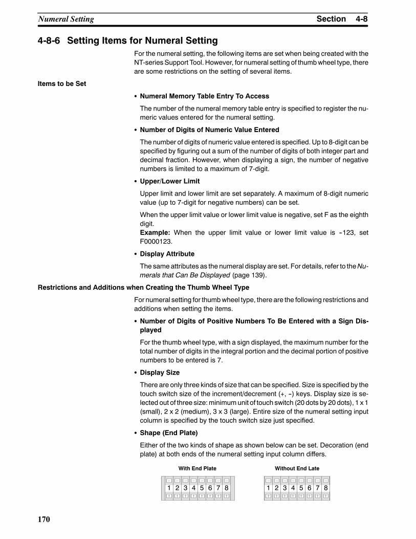
4-8SectionNumeral Setting
170
4-8-6 Setting Items for Numeral SettingFor the numeral setting, the following items are set when being created with theNT-series Support Tool. However, for numeral setting of thumbwheel type, thereare some restrictions on the setting of several items.
Items to be Set
S Numeral Memory Table Entry To Access
The number of the numeral memory table entry is specified to register the nu-meric values entered for the numeral setting.
S Number of Digits of Numeric Value Entered
The number of digits of numeric value entered is specified. Up to 8-digit can bespecified by figuring out a sum of the number of digits of both integer part anddecimal fraction. However, when displaying a sign, the number of negativenumbers is limited to a maximum of 7-digit.
S Upper/Lower Limit
Upper limit and lower limit are set separately. A maximum of 8-digit numericvalue (up to 7-digit for negative numbers) can be set.
When the upper limit value or lower limit value is negative, set F as the eighthdigit.Example: When the upper limit value or lower limit value is --123, setF0000123.
S Display Attribute
The sameattributes as the numeral display are set. For details, refer to theNu-merals that Can Be Displayed (page 139).
Restrictions and Additions when Creating the Thumb Wheel Type
For numeral setting for thumbwheel type, there are the following restrictions andadditions when setting the items.
S Number of Digits of Positive Numbers To Be Entered with a Sign Dis-played
For the thumb wheel type, with a sign displayed, the maximum number for thetotal number of digits in the integral portion and the decimal portion of positivenumbers to be entered is 7.
S Display Size
There are only three kinds of size that can be specified. Size is specified by thetouch switch size of the increment/decrement (+, --) keys. Display size is se-lected out of three size:minimumunit of touch switch (20 dots by 20 dots), 1 x 1(small), 2 x 2 (medium), 3 x 3 (large). Entire size of the numeral setting inputcolumn is specified by the touch switch size just specified.
S Shape (End Plate)
Either of the two kinds of shape as shown below can be set. Decoration (endplate) at both ends of the numeral setting input column differs.
With End Plate Without End Late
1 2 3 4 5 6 7 8 1 2 3 4 5 6 7 8

Reference
4-9SectionCharacter String Setting
171
S Restricted Display Attributes
There are the following restrictions on display attributes.
Character type: Wide size only
Character magnification: Either of double, x4, or x9 in correspon-dence with display size specified
Character display attribute: Normal display only (reverse and soforth are not available)
Zero suppress: Without zero suppress only
For details, refer to the Numerals that Can Be Displayed (page 139).
4-9 Character String SettingCharacter string setting (character string input) is a function for entering charac-ter strings on the screen.
The character string setting allows a character string to directly be entered fromthe touch switch into the character string memory table entry, displayed in thescreen, and also sent to the PC.
This section outlines the character string setting function and explains how to in-put character strings during operation.
For the actualmethod used to access input character strings at thePC, seeNoti-fying the PC of a Character String (page 227).
The character string setting is carried outwhen creating a screenwith theNT-se-ries Support Tool.
4-9-1 Functions of Character String SettingThe character string setting has the following functions.
(1) The touch switches (character key) are previously set by theNT-seriesSup-port Tool.
(2) When the character key (“NT30C” in an example in the figure) is pressed, aguidecharacter of the character key (“NT30C” in theexample in the figure) isentered in the character string setting input column.
(3) When the Enter ( ) key is pressed, the character string of the characterstring input column is written into the character string memory table entryand simultaneously notified to the PC.
PCNT30C
NT30/30C
Enter
Notify
NT30C
Character string setting input column
NT30C NT610C
Write +
Character string memory tableentry
NT30
Display
S By using the pop-up window function (see page 173), it is possible to selectandopenanumber ofwindows (keypads), eachofwhich comprises a numberof character keys, thus allowing various types of input.
S Input to character string setting input fields can be disabled by a system con-trol (PT Status Control Area) operation.

Reference
Reference
4-9SectionCharacter String Setting
172
4-9-2 How to Enter Character StringsAn appropriate character string setting input column must be specified to beready for an input operation before a character string is entered by the characterkey.
S Specifying the Character String Setting Input Column To Be Entered
The character string setting input column to be entered is specified by eitherten-key, system key, or touch switch (numeral/character string setting cursormoving key).
The frame (cursor) around the specified character string setting input columnand the cursor attributes can be specified.
Concrete specifyingmethod is the sameasnumeral setting.Refer to theSpec-ifying the Numeral Setting Input Column to be Entered (page 165).
Thewindowopening function canbe set for cursormoving keys. For details, see4-10 Pop-Up Window Function (page 173).
S Entering the Character String
The character strings are displayed in the input column of the character stringsetting in due order of the touch switches being pressed (A character is in-serted at an input cursor position). At this time, the keyboard screen can alsobe switched over halfway.
When entering the character strings, the following control keys of the touchswitches can be used.
Control Key Function
CA Used to cancel character string entry
BS Used to delete a character just before an input cursor
DEL Used to delete a character at an input cursor
A Used to move an input cursor to the left by one character
" Used to move an input cursor to the right by one character
ENT Used to confirm an input character (After confirming this, a cursormoves to the following input column)
Be sure to press the Enter ( ) key after an input operation is completed. Atthis time, the character strings being displayed are written into the characterstring memory table entry and simultaneously notified to the host.
S In order tomake character string settings, a key to confirm character string inputis required. Allocate the Enter ( ) or ENT control key to a touch switch tocreate this key.
S It is also possible to use the control keys of the input key function (however, thefour keys used for alarm display cannot be used).
S By switching between windows, a large number of character keys can be used.It is also possible to create a temporary input field in a window to allow the exist-ing data to be checked while inputting new data. For details, see 4-10 Pop-UpWindow Function (page 173).
S Using copy keys (page 160) allows you to input the value or code (constant)stored in a character string memory table entry into a character string settinginput field in a one-touch operation.

Reference
4-10SectionPop-Up Window Function
173
Examples:
- When the “Model NT30C-”
NT30C- Character string setting input column
Character keys
NT30- NT30C-
ST131-E ST141-E
ST131B-E ST141B-E
- Then, when the “ST141-E”
Character string settingNT30C-ST141-E
NT30- NT30C-
ST131-E ST141-E
ST131B-E ST141B-E
Character keys
• Finally, when the Enter ( ) key is pressed, the “Model NT30C-ST141-E” dis-played in the input column of the character string setting is confirmed andwrit-ten into the character stringmemory table entry and simultaneously notified tothe PC.
4-10 Pop-Up Window FunctionThe NT30/30C features a pop-up window function, which is used to display win-dows overlaying the currently displayed screen (base screen). These windowscan be opened whenever required by pressing touch switches.
Thepop-upwindow function can only be usedwith Ver.3 and later versions of thedirect connection function (with Ver.3, the windows can only be used as key-boards).
The opening ofwindows can be disabled by a system control (PTStatusControlArea) operation.

Reference
4-10SectionPop-Up Window Function
174
4-10-1 Functions of Pop-Up Windows
The functions of pop-up windows are described below.
What is a Window? A window is a screen that can be displayed overlaying a currently displayedscreen (thebase screen). Its sizeanddisplayposition canbechanged.Windowsare mainly used for the following applications.
• An explanatory message can be registered in a window, enabling it to be usedas a HELP screen during an operation.
Press here Window opens
HELP HELP
Controltheconveyor.
• By registering multiple character keys (touch switches) for use in characterstring setting, windows required for specific purposes can be displayedwhen-ever necessary, allowing various types of input.
Character string setting input field
lettersnumerals
Press “numerals”
Window for numerals
Press “letters”
Window for letters
lettersnumerals
1 2 34 5 6
lettersnumerals
A B CD E F
In order tomake character string settings, a key to confirm character string in-put is required. Allocate the Enter ( ) or ENT control key to a touch switch tocreate this key.

Reference
4-10SectionPop-Up Window Function
175
• By registering multiple screen switching keys (touch switches), menus forscreen switching can be created.
When “Graph” is pressed
When “Next”is pressed
Press here
MENU MENU
GraphNext
MENUMENU
Window Screens and Display Elements
Using the pop-up window function, windows can be created in the screens num-bered 1900 to 1979 (note that a screen for which awindow is registered is calleda window screen). Screens other than these cannot be opened as windows.Screenafter creatingawindow in thescreennumber range1900 to1979, specifythewindowarea (displayarea). Thewindowwill thenopen inadisplayareaof thespecified size and at the specified position.
The following elements can be displayed inNT30/30Cwindows. If elements oth-er than these are registered on awindow screen, theywill not be displayedwhenthe window opens.
• Background color screen attribute (NT30C only)
• Fixed displays
• Touch switches (but the input notification and screen print functions cannot beused)
• Numeral/character string input setting fields (only one can be used)
Elements that project beyond thedisplay areawill not bedisplayedwhen thewin-dow opens. Similarly, display elements on the base screen that overlap evenpartly with the window will be deleted when the window opens.
S Since the pop-up window function and screen print function share the samememory area, it is not possible to open a window during screen printing. Con-versely, a screen cannot be printed while a window is open.
S The display elements in a window cannot be notified to the PC. This meansthat the lamp bits of touch switches in windows cannot be controlled.
S While a window is open, display processing may be slightly delayed.

Reference
4-10SectionPop-Up Window Function
176
4-10-2Opening and Closing Windows
Windows are opened and closed by using touch switches with the pop-up win-dow/keyboard function: either the window keys or cursor moving keys.
Opening and Closing Windows with the Window Keys
Window keys can be used in the following way to open and close windows (notethat window keys can be created either on the base screen or in a window).
Open: When the touch switch is pressed, the specified windowopens. If another window is open when the touch switch ispressed, it is closed first before the specified window isopened. If the specified window is already open, nothinghappens.
Close: When the touch switch is pressed, the open window isclosed.
Open/Close: The specified window opened if it is not open, and closed ifit is open. If another window is open, it is closed first andthen the specified window is opened.
Base screen
No change if “CLOSE” is pressed No change if “Screen 1” is pressed
Base screenScreen 1
Base screen
Screen 2
Window 1 openWindow 2 open/close
Window 1 close
“Screen 1” pressed
“CLOSE” pressed
“Screen 1”pressed
“Screen 2”pressed
“Screen 2” pressed
“Screen 2” pressed
“CLOSE” pressed
Screen 1Screen 2CLOSE
Screen 1Screen 2CLOSE
Screen 1Screen 2CLOSE
If an attempt is made to open a window that has not been registered, no windowis opened (if a window is currently open, it will be closed).
It is not possible to openmore thanonewindowat the same time. Ifmultiple over-lapping child screens are registered for an parent screen, only the first childscreen will be applicable.
On switching to another screen, an open window will be automatically closed.
When creating a screenwith the NT-series Support Tool, it is possible to specifya window to be displayed when the screen is displayed (an initial window).Withthe Windows version, this is performed using the screen attribute Load Local 1(Keyboard) and with the DOS version it is performed using Keyboard/WindowDisplay under Input Settings.

4-10SectionPop-Up Window Function
177
Opening Windows with the Cursor Moving Keys
It is possible to set a window key open function for the cursor moving keys usedfor numeral/character string setting, in addition to their cursor moving function.Doing thismakes it possible to specify an input field and also display the windowto be used in a one touch operation.
If another window is openwhen the cursormoving key is pressed, that window isclosed first before the specified window is opened (the cursor also moves to thespecified input field). If the specifiedwindow is alreadyopen, the cursormoves tothe relevant input field but nothing else happens.
--41.8
ABCDE1 2 3
4 5 6
1 2 3 4 5 6
--41.8
ABCDE
1 2 3 4 5 6
Numeral/character stringsetting input field
Numeral/character stringsetting input field
Top touchswitchpressed
Touch switch for which cursormoving and window openingfunctions have been set
Specified window opens
If the cursormoving keys are created automatically during creation of a numeral/character string input field with the NT-series Support Tool, the window openingfunction is not set. In this case, the window to be opened can be specified bymodifying the touch switch.
4-10-3 Temporary Input FieldsOnly one numeral or character string setting input field can be registered for awindow. This input field can be used - in combination with a number of numeraland character string input fields on base screens - for provisional input beforeanydata is input into theactual input field on the base screen. This kind of numer-al or character string input field in a window is called a temporary input field. Itsadvantage is that entries can be input into the temporary input field while check-ing the current setting on the base screen.
However, if the temporary input field in thewindowand the input field on the basescreen are not of the same type, the temporary input field will not be displayed.Note also that temporary input fields cannot be used for thumb wheel type inputfields.
The temporary input field will also be unusable and not displayed if it has fewerdigits than the actual input field on the base screen (number of integer digits +number of decimal fraction digits + digit for decimal point + digit for sign).
If it is not possible to use a temporary input field, the data has to be input directlyonto the base screen.
How to Input Data Into Temporary Input Fields
Temporary input fields are used in the following way.
(1) Specify the numeral/character string input field used for actual input with anumeric key, system key, or touch switch (cursor moving key).
Theactualmethodused for specification is the sameas that for numeral set-ting. SeeSpecifying the Numeral Setting Input Column to be Entered (page165).

4-10SectionPop-Up Window Function
178
Numeral setting input Temporary input field (displays data being input)
Current setting Window
1 2 3 4 5 6
-- 4 1.8
0 0 2 .710
7 8 9 ↑4 5 6 ↓
1 2 3 ±0 . ENT
555 .440
It is possible to display a window simultaneously with a cursor movement.For details, seeOpeningWindowswith theCursorMovingKeys (page177).
(2) If thewindow inwhich the temporary input field is registered is not displayed,open it (this could also be done prior to step (1)). For themethod for openingthe window, see Opening and Closing Windows (page 176).
The temporary input field displays thecontents of theactual input field at thatpoint in time. The display of the temporary input field is governed by the fol-lowing attributes:
• Attributes determined by the settings for the temporary input field:Character font, scale, display attribute, smoothing, character color, back-ground color
• Attributes determined by the settings for the actual input field on the basescreen:Numbers of integer and decimal fraction digits, upper limit value, lower limitvalue, decimal/hexadecimal, zero suppress, sign display.
The cursor frame of the temporary input field is always displayed.
(3) Input the numerical value or character string. The method is the same asthat normally used to input numerical values and character strings. SeeEn-tering theNumeralValues (page167), orHow toEnter theCharacterStrings(page 172).
The numerical value or character string is input into the temporary inputfield.
(4) The input numerical value of character string is written to the input field onthe base screen on confirming it by pressing the ENT key or the return key( ), and the contents of the corresponding numeral/character stringmemory table entry are changed accordingly (notification to the PC alsotakes place at this time). On confirming by pressing the ENT key, the cursormoves to the next input field on the base screen.
If the input value is outside the range delimited by the upper and lower limitvalues, the original value is redisplayed.
Note also that if the actual input field on the base screen is changed beforeinput is confirmed, the input data will be destroyed. The input data will alsobe destroyed if the window is closed or the screen is switched before con-firmation.

4-10SectionPop-Up Window Function
179
Operation Example Temporary input operation example
↑
00. 03
Base Screen5 input settings Window
Integer digits: 8; Decimal fraction digits: 0;Sign display: No; Zero suppress: NoInteger digits: 8; Decimal fraction digits: 0;Sign display: No; Zero suppress: YesInteger digits: 2; Decimal fraction digits: 2;Sign display: No; Zero suppress: NoInteger digits: 2; Decimal fraction digits: 2;Sign display: Yes; Zero suppress: NoInteger digits: 8; Decimal fraction digits: 0;Sign display: Yes; Zero suppress: No
Numeric key Window open key
Temporary input field8 integer digits, nosign display (8 digitscan be displayed)
Control keys
Open windowDisplay set data
Confirm, notify PCMove frameDisplay set data
Move frameDisplay set data
Move frameDisplay set data
Move frameNumber of input digits exceededDelete temporary input field
7 8 9
4 5 6
1 2 3
0 . ±
↓
↑
CLR
ENT
00000001
00. 03
--00. 04
--00000005
2
Numeric key
00000001
00. 03
--00. 04
--00000005
2 7 8 9
4 5 6
1 2 3
0 . ±
↓
↑
CLR
ENT
Numeric key
00000001
00. 03
--00. 04
--00000005
2 7 8 9
4 5 6
1 2 3
0 . ±
↓
↑
CLR
ENT
Numeric key
00000178
00. 03
--00. 04
--00000005
2 7 8 9
4 5 6
1 2 3
0 . ±
↓
↑
CLR
ENT
Numeric key
00000178
--00. 04
--00000005
2 7 8 9
4 5 6
1 2 3
0 . ±
↓
↑
CLR
ENT
Numeric key
00000178
00. 03
--00. 04
--00000005
2 7 8 9
4 5 6
1 2 3
0 . ±
↓
↑
CLR
ENT
Numeric key
00000178
00. 03
--00. 04
--00000005
2 7 8 9
4 5 6
1 2 3
0 . ±
↓
↑
CLR
ENT
Numeric key
7
8
ENT0000017800000001
00. 03 01.03 01.501 .
5
00. 03
00000178
--00. 04
--00000005
2 7 8 9
4 5 6
1 2 3
0 . ±
↓CLR
ENT
Numeric key
00000178
00. 03
--00. 04
--00000005
2 7 8 9
4 5 6
1 2 3
0 . ±
↓
↑
CLR
ENT
Numeric key
00000178
00. 03
--00. 04
--00000005
2 7 8 9
4 5 6
1 2 3
0 . ±
↓
↑
CLR
ENT
Numeric key
--00. 04 03.80.
8
3
±
↓
↓
↓
2

Caution
4-11SectionAlarm List & History Display Functions
180
4-11 Alarm List & History Display FunctionsTheNT30/30C canmonitor the state of PC bits of the host and display the corre-sponding message (using the character string memory table entry) or image/li-brary data (alarm list display) when a specific bit becomes 1 (ON).
The NT30/30C can record that those bits become 1 (ON) and also display themin the order of frequency or occurrence (alarm history display).
Since the alarm list/history data are backed up by the built-in battery, they are notlost when the power is turned OFF.
If not backed up by the built-in battery, the memory switch settings will all be ini-tialized to the values set with the NT-series Support Tool when the power isturned OFF.If the message “Battery Lowered” is displayed while the NT30/30C is beingused, replace the built-in battery immediately. For details on how to replace thebattery, see Replacing the Battery (page 253).
4-11-1 Alarm List DisplayAlarm list display has the following functions.
Displaying a Message (Character String Memory Table Entry) or Image/Library Data
The NT30/30C monitors multiple bits according to the setting of the bit memorytableentryanddisplays thecharacter stringmemory tableentry (message) set tothe corresponding bit memory table entry when there is any bit that becomes 1(ON). Since the display column of amessage is also a touch switch, correspond-ing image/library data can be displayed by pressing the message being dis-played.
If the description of alarms is provided in the character stringmemory table entryand the corrective actions against those alarms are described for the image/li-brary data, it is possible to take appropriate measures rapidly.
S To Display Multiple Messages
When multiple bits become 1 (ON), the bit memory table entry with smallertable entry number is displayed preferentially.
When multiple messages can be displayed, the messages of higher priority(smaller bit memory table entry number) will be displayed earlier.
The display column of message and the image/library data displayed corre-spondingly are referred to as AlarmGroup collectively. TheNT30/30C can dis-play up to four individual alarm group on one screen and simultaneously showup to 12 messages in one alarm group.

4-11SectionAlarm List & History Display Functions
181
Example:
No. 13
No. 14
No. 15
PC010
1 (ON)
Character String tableentry No. 54Library data FD34
Character String table entry No.32
Image dataFE68
BitCharacter String tableentry No. 50Image data FE52Character String tableentry No. 32Image data FE68
Message (character string No. 32)set to bit memory table entry num-ber 14
A000000L001003D010015
When the message displayed is pressed, the image data(FE68) set to the bit memory table entry number 14 is dis-played.
Now, when A000000 turns ON
No. 13
No. 14
No. 15
PC110
1 (ON)
Character String table entryNo. 54Library data FD34
Character String table entryNo. 50
Image dataFE52
BitCharacter String tableentry No. 50Image data FE52Character String table entryNo. 32Image data FE68
Character String table entryNo. 32
Message (character string 50) set tobit memory table entry number 13
A000000L001003D010015
When the upper message displayed is pressed, the image data(FE52) set to the bit memory table entry number 13 is displayed.
Character String table entry 32
When the bit corresponding to the message being displayed returns to 0(OFF), themessage is cleared and the nextmessage is displayedaccording tothe order of priority.
S Scrolling the Message
When the message issued extends more than the number of lines set to mes-sage display, the message being displayed can be scrolled in unit of line orpage.
When the number of lines formessagedisplay is set to four ormore, the controlkeys for scrolling are automatically created as shown below.
Y z Previous line scrolling key
z Previous page scrolling key
z Next page scrolling key
B z Next line scrolling key"
Message display column
When the number of lines for message display is set to one to three, only linescrolling keys are automatically created.
The scrolling key can also be set and corrected with control code input functioncontrol keys. (When the scrolling key has been created independently, it is nec-essary to perform Associate With for the alarm history.)

4-11SectionAlarm List & History Display Functions
182
S Scrolling Keys Shown in Reverse Video
Since these scrolling keys are automatically shown in reverse video whenthere are anymessages in front or behind those keys, it is foundwhether or notthere are any messages that are not displayed.
Switching the Image/Library Data to be Displayed
The message display column also serves as a touch switch. By selecting themessage (touch switch) displayed, corresponding image/library data can bedis-played.
Switching Over to the Corresponding Screen
To the bitmemory table entry used for the alarm list display function, correspond-ing screennumber canbeset, aswell as correspondingcharacter stringmemorytable entry (message) and image/library data.
When thescreennumberhasbeenset, bypressing themessageonceagain thatis being selected in the section above Switching the image/library data to be dis-played, it is possible to switch over to and display that screen.
Example:
Character String table entryNo. 50
Image dataFE68
Character String table entryNo. 32
Message
When the secondmessage is pressed
Image data correspondingto the second message
When the same mes-sage is pressed again
Screen corresponding tothe second message
Screen 32
Return
Setting the Alarm List Display Function (Setting the Bit Memory Table Entry)
When the alarm list display function is used, it is necessary to set the bit memorytable entry and screen display function. This paragraph describes the setting ofthebitmemory tableentry. For thedisplay setting, refer toNT-seriesSupport Toolfor Windows Operation Manual (V061).
In order to set the message to consecutive or overlapping screens, only the firstsub-screen is effective.
In onealarmgroup, the bitmemory table entries less than continuous 128 canbeusedand the state of up to 128bits canbemonitored. Thesmaller thebitmemorytable entry number, the higher the order of priority a massage has.
The following settings are done to each bit memory table entry.
S Recording the Alarm History
Setting of whether or not a change of PCbit to which the bitmemory table entryis assigned is recorded.
S Screen Switchover Function
Setting of whether or not the screen switchover function is used.
S Character String Memory Table Entry Number
Character string memory table entry number displayed as a message is set.

4-11SectionAlarm List & History Display Functions
183
S Display Color (NT30C Only)
Character color of a message is set.
S Image/Library Data
Code of image/library data displayed together with a message is set.
S Screen Switchover
Screen number displayed by the alarm list and history display function is set.
S Bit (PC Address)
Bit in the PC, to which the bit memory table entry is assigned, is set.
f: Possible×: Impossible
Sym-bol C Series PC Alloca-
tion CVM1/CV Series PC Alloca-tion CS1 Series PC Alloca-
tion
DM DM Area f DM Area f DM Area f
CH IR Area f CIO Area f CIO Area f
TIM Timer Area × Timer × Timer ×CNT Counter Area × Counter Area × Counter Area ×HR HR Area f -- -- HR Area ×AR AR Area f Auxiliary Area × Auxiliary Area ×LR LR Area f -- -- -- --
The Auxiliary Area of CV series PC is used exclusively for special applications inthe system, and cannot be used for other application.
When specifying the DMArea, specify the bit number (00 to 15) along with theword address.
Example of setting:
No. Host # Tableentry Dsp Cl Image
& Lib SwScreen Bit Comment
000 No No ------------
001 No No ------------
002 Ys No 999 Red FD20 2000 CH000000
003 Ys No 123 Blue FD21 1234 AR000000
004 No No 124 Whit FD22 1235 LR 001003
005 No No 125 Whit FD23 1236 LR 001004
006 No No ------------
007 No No ------------
In this example, four bits IR/CIO 000000, AR 000000, LR 001003, LR 001004are monitored using four bit memory table entries of bit memory table entrynumbers 002 to 005.

Reference
4-11SectionAlarm List & History Display Functions
184
4-11-2 Displaying the Alarm History
The alarm history constantly monitors the status of the bit for which Alarm isturnedON under Function in the bit memory table and records the date and timeat which it changes to 1 (i.e., turns ON).
The bits recorded in the alarm history are always monitored irrespective of thedisplay screen of the NT30/30C. If the number of bits are increased excessively,the processing speed of the NT30/30C may become slower.
The alarm history is common to all bit memory table entries. Unlike themessagedisplay, it cannot deal with only a part of bit memory table entry.
Recording Format of Alarm History
For the alarm history, the following data is recorded in the memory concerningthe bit that turns 1 (ON).
• Bit address
• Date and time of occurrence
• Message set in the bit memory table entry (the contents of the character stringmemory table entry)
Maximum Number of Alarms to be Recorded
The maximum number of alarms that can be recorded is 256 when they are re-corded in the order of occurrence, and 255 for each alarm message when theyare recorded in the order of frequency.
Data recorded is backed up by a battery, so it is not lost even when the powersupply is turned OFF.
If the battery in thePT loses voltage, recorded data cannot be retained correctly.
When recording in the order of occurrence, the way alarms are recorded whenthe number of alarms capable of being recorded is exceeded is determined bythe Alarm (Use Ring Buffer) under System (Alarm First-in First-out setting of theSystem Memory with DOS version) on the NT-series Support Tool as follows:
ON: Old history is cleared and new history is recorded.OFF: Alarms in excess of 256 are not recorded (new alarms are discarded).
In order to clear (initialize) the alarm history, the memory is initialized (see page82). It is also possible to clear (initialize) the alarm history using bit 11 (displayhistory initialization) of the PT status control bits.
How to Make Sure of Alarm History
The alarm history can be displayed by the NT30/30C during operation by settingan area and displaying method when creating a screen data with the NT-seriesSupport Tool.
There are two displaying methods: in the order of occurrence and frequency.
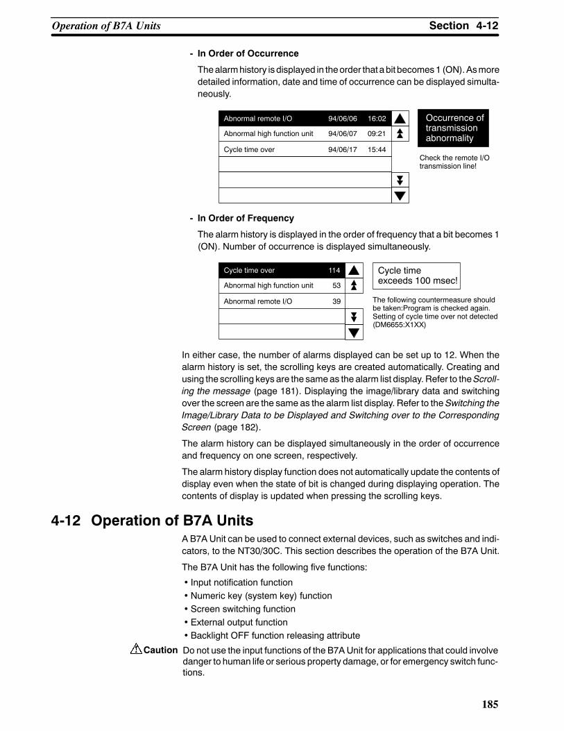
Caution
4-12SectionOperation of B7A Units
185
- In Order of Occurrence
Thealarmhistory is displayed in theorder thatabit becomes1 (ON).Asmoredetailed information, date and time of occurrence can be displayed simulta-neously.
Check the remote I/Otransmission line!
Abnormal remote I/O 94/06/06 16:02
Abnormal high function unit 94/06/07 09:21
Cycle time over 94/06/17 15:44
Occurrence oftransmissionabnormality
- In Order of Frequency
The alarm history is displayed in the order of frequency that a bit becomes 1(ON). Number of occurrence is displayed simultaneously.
Cycle time over 114
Abnormal high function unit 153
Abnormal remote I/O 139 The following countermeasure shouldbe taken:Program is checked again.Setting of cycle time over not detected(DM6655:X1XX)
Cycle timeexceeds 100 msec!
In either case, the number of alarms displayed can be set up to 12. When thealarm history is set, the scrolling keys are created automatically. Creating andusing the scrolling keys are the sameas the alarm list display. Refer to theScroll-ing the message (page 181). Displaying the image/library data and switchingover the screen are the same as the alarm list display. Refer to the Switching theImage/Library Data to be Displayed and Switching over to the CorrespondingScreen (page 182).
The alarm history can be displayed simultaneously in the order of occurrenceand frequency on one screen, respectively.
The alarm history display function does not automatically update the contents ofdisplay even when the state of bit is changed during displaying operation. Thecontents of display is updated when pressing the scrolling keys.
4-12 Operation of B7A UnitsA B7A Unit can be used to connect external devices, such as switches and indi-cators, to the NT30/30C. This section describes the operation of the B7A Unit.
The B7A Unit has the following five functions:
• Input notification function• Numeric key (system key) function• Screen switching function• External output function• Backlight OFF function releasing attribute
Do not use the input functions of the B7AUnit for applications that could involvedanger to human life or serious property damage, or for emergency switch func-tions.

Reference
4-12SectionOperation of B7A Units
186
In order to use expansion I/O, the B7A Interface Unit intended specifically forexpanded I/O must be installed on the NT30/NT30C and connected to the B7AUnit by cable. For the installation and connection methods, see 2-9 Connectionof Expanded I/O (page 64).
Assignment of Functions Toperformexternal I/O, an externally installedB7AUnitmust be used. There arethree types of B7A Unit, with the following I/O characteristics.
16 input points:Corresponding to expanded I/O outputs with expanded I/O Nos. 0 to 15.
16 output points:Corresponding to expanded I/O outputs with expanded I/O Nos. 0 to 15.
8 input points/8 output points:Inputs andoutputs correspond toexpanded I/O inputNos. 0 to7andexpand-ed I/O output Nos. 0 to 7 respectively.
When creating screens with the NT-series Support Tool, functions such asinput notification, numeric key (system key), screen switching, and externaloutput can be allocated without restriction to each I/O terminal of the B7AUnit.
4-12-1 Contents of FunctionsDetails of each function are as follows:
S Input Notifying Function
With thePCbits assigned to the input terminals, the state of input terminals canbe notified to the PC by turning ON/OFF the bits specified in accordance withthe state of the input terminals.
At this time, even when the bits are turned ON simultaneously with the touchswitches or multiple terminals, all input states are notified to the PC.
BitON
NT30/30C PC
Notified to the PC
Input terminal ON

Reference
Reference
4-12SectionOperation of B7A Units
187
S Numeric Key (System Key) Function
With the numeric keys (system keys) assigned to the input terminals, the inputterminals can function similar to those keys specified. However, with the sys-tem keys assigned to the input terminals, those terminals cannot be used asthe system keys other than the operation mode (system menu, etc.).
The following numeric keys (system keys) can be assigned to the input termi-nals.
Numeric key Numeric key Numeric key(system key)
0 A "
1 B #
2 C z
3 D !
4 E
5 F
6 CLR
7 +/--
8 . MENU
9 HOME
When a screen switchover key for each screen is also assigned to the same in-put terminal, it acts as the screen switchover key.
S Stand Alone Function
With the screen number assigned to the input terminal, it can function as thescreen switchover key similar to the touch switch. However, with 0 specified tothe screen number, it functions as the screen switchover return key (see page157).
Other than setting the input terminal as the screen switchover key that acts ateach screen similar to the touch switch, it can also be set as the screen switch-over key common to all screens. However, when the screen number commontoall screensand thescreennumber for each screenareassignedconcurrent-ly to one input terminal, the screen number for each screen have priority.
With theWindows version of theNT-series Support Tool, setting for each screenis not possible. The terminal will always be used as the switchover key for allscreens.
S External Output Function
With the PC bits assigned to the output terminals, those output terminals canbe turned ON/OFF in accordance with the state of the bits to which the outputterminals are specified. External equipment connected to the output terminalscan be controlled by the PC.
ON/OFF state of the output terminal is held unless the state of the bit ischanged.

Reference
4-12SectionOperation of B7A Units
188
S Screen Saver Function Releasing Attribute
With this attribute set to an input terminal, an OFF state is released when theinput terminal turnsON,even if thebacklight is turnedOFFwith the screensav-er function activated (see page 95).
However, for the terminals to which both numeric key and screen switchoverfunctions are assigned, the screen saver function is always released. For theterminals to which the input notifying function is assigned and the terminals towhich any function is not assigned, screen saver attribute and not-release at-tribute can be selected.
For example, with the screen saver attribute set to the terminals without thisfunction, the PT screen can be displayed when a person approaches to theNT30/30C, by combining with a sensor as shown below.
Duringoperation
B7A UnitApproaching person
Input terminal: without function, Backlight Off
NT30/30C
When turningON the terminal to which both screen switchover key and numerickey functions are assigned, with the screen saver, only the screen saver state isreleased and the function of those keys will not be implemented. However, incase of input notifying key, it is notified to the PC irrespective of the screen saverrelease attribute.
S Key Press Sound
Though a key press sound does not sound under any circumstances for theinput notifying key, sound or no sound can be selected for other function andnon-function keys according to the memory switch setting (see page 92).

189
SECTION 5Using Host Link and NT Link
This section describes how the NT30/30C can be used when using the Host Link and NT link.
5-1 Outline of Host Link and NT Link Operations 190. . . . . . . . . . . . . . . . . . . . . . . . . . . . . . . . . .5-1-1 Equipment and Settings Used in This Chapter 190. . . . . . . . . . . . . . . . . . . . . . . . . . .5-1-2 Allocatable Bits and Words 190. . . . . . . . . . . . . . . . . . . . . . . . . . . . . . . . . . . . . . . . .5-1-3 NT30/30C Status Control and Notification to PC 191. . . . . . . . . . . . . . . . . . . . . . . .5-1-4 Switching the Screen Display Using the PT Status Control Area 195. . . . . . . . . . . .5-1-5 Switching the Screen Display Using a Bit Memory Table Entry 197. . . . . . . . . . . . .5-1-6 Notification of Number of Currently Displayed Screen 199. . . . . . . . . . . . . . . . . . . .
5-2 Memory Tables and Graphs 201. . . . . . . . . . . . . . . . . . . . . . . . . . . . . . . . . . . . . . . . . . . . . . . .5-2-1 Allocated Words and Display of the Memory Tables 205. . . . . . . . . . . . . . . . . . . . . .5-2-2 Changing Displayed Numerals or Character Strings, Direct Specification 207. . . . .5-2-3 Changing Displayed Numerals or Character Strings, Indirect Specification 209. . . .5-2-4 Copying Memory Table Entries 212. . . . . . . . . . . . . . . . . . . . . . . . . . . . . . . . . . . . . .5-2-5 Upgrading Graphs 215. . . . . . . . . . . . . . . . . . . . . . . . . . . . . . . . . . . . . . . . . . . . . . . .
5-3 Lamps and Touch Switches 216. . . . . . . . . . . . . . . . . . . . . . . . . . . . . . . . . . . . . . . . . . . . . . . .5-3-1 Allocated Bits and Display of Lamps 216. . . . . . . . . . . . . . . . . . . . . . . . . . . . . . . . . .5-3-2 Turning ON and OFF Lamps 216. . . . . . . . . . . . . . . . . . . . . . . . . . . . . . . . . . . . . . . .5-3-3 Allocated Bits, and Display, of Touch Switches 218. . . . . . . . . . . . . . . . . . . . . . . . .5-3-4 Touch Switch Status 220. . . . . . . . . . . . . . . . . . . . . . . . . . . . . . . . . . . . . . . . . . . . . . .5-3-5 Notifying the PC that a Switch Has Been Pressed 220. . . . . . . . . . . . . . . . . . . . . . . .
5-4 Numeral and Character String Setting 224. . . . . . . . . . . . . . . . . . . . . . . . . . . . . . . . . . . . . . . .5-4-1 Notification of Numbers to the PC 224. . . . . . . . . . . . . . . . . . . . . . . . . . . . . . . . . . . .5-4-2 Notification of Character String to the PC 227. . . . . . . . . . . . . . . . . . . . . . . . . . . . . .
5-5 Alarm Lists 229. . . . . . . . . . . . . . . . . . . . . . . . . . . . . . . . . . . . . . . . . . . . . . . . . . . . . . . . . . . . .5-5-1 Allocated Bits of Bit Memory Table 229. . . . . . . . . . . . . . . . . . . . . . . . . . . . . . . . . .5-5-2 Displaying Alarm Lists Using Bit Memory Table Entries 230. . . . . . . . . . . . . . . . . .
5-6 Clock Function 234. . . . . . . . . . . . . . . . . . . . . . . . . . . . . . . . . . . . . . . . . . . . . . . . . . . . . . . . . .5-6-1 About the Clock Function 234. . . . . . . . . . . . . . . . . . . . . . . . . . . . . . . . . . . . . . . . . .5-6-2 Date and Time Display 234. . . . . . . . . . . . . . . . . . . . . . . . . . . . . . . . . . . . . . . . . . . . .5-6-3 Date and Time Setting 235. . . . . . . . . . . . . . . . . . . . . . . . . . . . . . . . . . . . . . . . . . . . .5-6-4 Notification of the Date and Time to the PC 238. . . . . . . . . . . . . . . . . . . . . . . . . . . .
5-7 NT30/30C Status Control 239. . . . . . . . . . . . . . . . . . . . . . . . . . . . . . . . . . . . . . . . . . . . . . . . . .5-7-1 Controllable NT30/30C Functions 240. . . . . . . . . . . . . . . . . . . . . . . . . . . . . . . . . . . .5-7-2 How to Control NT30/30C Functions 242. . . . . . . . . . . . . . . . . . . . . . . . . . . . . . . . .
5-8 Notifying the PC of PT Operating Status 244. . . . . . . . . . . . . . . . . . . . . . . . . . . . . . . . . . . . . .5-8-1 Accessing NT30/30C Status 244. . . . . . . . . . . . . . . . . . . . . . . . . . . . . . . . . . . . . . . . .5-8-2 Reading NT30/30C Operating Status 245. . . . . . . . . . . . . . . . . . . . . . . . . . . . . . . . . .

5-1SectionOutline of Host Link and NT Link Operations
190
5-1 Outline of Host Link and NT Link OperationsThis section explains the fundamentals when using the Host Link/NT link - allo-cated bits and words, and the method for control of the NT30/NT30C and notifi-cation to the PC - and also describes the actual procedure used for screenswitching.
5-1-1 Equipment and Settings Used in This ChapterThe following equipment and settings are used in the examples in this Chapter:
Devices PT: NT30-ST131-E
PC: CQM1
Software: NT-series Support Tool Ver.j
NT-series Support Tool settings
PT model: 30
Memory capacity: 512 KB
PC model: OMRON
5-1-2 Allocatable Bits and WordsThe names of the bits and words that are allocated to the PC at the NT-seriesSupport Tool, and the areas for each PCmodel, correspond in the followingway.The types of area that can be allocated to display elements depends on the typeof display elements. For details, refer to the explanations of the allocations foreach type of display element in this section. The range of respective area varieswith the type of PC. Refer to Appendix J PC Memory Maps (page 293).
The allocations must be made without exceeding respective area range.
OMRON PCs
Symbol Name used on the NT-series Support Tool
C-series PCs CVM1 and CV-seriesPCs
CS1-series PCs
D DM Area DM Area DM Area DM Area
None CIO Area IR Area CIO Area CIO Area
T Timer Timer Area Timer Area Timer Area
C Counter Counter Area Counter Area Counter Area
H HR Area HR Area -- HR Area
A Auxiliary Area AR Area Auxiliary Area Auxiliary Area
L Link Relay LR Area -- --
When allocating memory table entries to words, the allocation must not exceedthe word area.
The Auxiliary Area of a CV-series PC is allocated to the system and cannot beused for purposes other than the system use. However, reading from this area ispossible.
One allocation for amemory table entry can use up to 2 consecutivewords in thecase of numeral memory table entries or 16words in the case of character stringmemory table entries.

5-1SectionOutline of Host Link and NT Link Operations
191
5-1-3 NT30/30C Status Control and Notification to PCThis section describes the fundamentals of the display elements, NT30/30C sta-tus control, and notification, which are the basics of the NT30/30C functions.
For details on using the PT Status Control Area and the PT Status Notify Area,refer to5-7NT30/30CStatusControl (page239) and5-8Notificationof theOper-ating Status to the PC (page 244).
Controlling the Display Elements Using Allocated Bits and Words
TheNT30/30Cwill operate as describedbelow in the display element control op-eration.
NT30/30C Operation
(1) TheNT30/30C checks the allocation bits andwords of the display elementsand makes an inquiry to the PC.
(2) The PC answers the NT30/30C about the bit and word data.
(3) The NT30/30C changes the display status according to the bits and wordsobtained from the PC.
NT30/30C Operation Example
Lamp 0
DM0100 to DM0102?
IR/CIO 010012 NT30/30CPC
(“a”, “b”)(“c”, “d”)(“e”, “f”)
IR/CIO 010012
Character string memory table entry Numeral memory table entry0First word: DM0100, First word: TIM003Number of saved words: 3 Number of saved words: 1
TIM003
Controlling the NT30/30C Status Using Allocated Bits and Words ..... PT Status Control Area (PC to PT)
The PT Status Control Area (PC to PT) is provided to control the NT30/30C sta-tus from the PC. When data is written to this area in the PC, the NT30/30C willread the data and operates according to the data. The PT Status Control Area isconfigured as four consecutive words as shown below.
0
Copy type
0 0 0 0 0
The first word (word n) of the PTStatus Control Areamust be set with the NT-se-ries Support Tool.
Word 15 14 13 12 11 10 9 8 7 6 5 4 3 2 1 0 Bit
Screen No. (4-digit BCD)Screen switchsetting
Copy memorytable entry set-tingCopy destination memory table entry # (3-digit BCD)
Copy source memory table entry # (3-digit BCD)
PT status control bitsPT status con-trol
n
n+1
n+2
n+3

Correct use
5-1SectionOutline of Host Link and NT Link Operations
192
The PT Status Control Area (PC to PT) can be allocated words in the followingPC areas.
f: Possible×: Impossible
Sym-bol C Series PC Alloca-
tion CVM1/CV Series PC Alloca-tion CS1 Series PC Alloca-
tion
DM DM Area f DM Area f DM Area f
CH IR Area f CIO Area f CIO Area f
TIM Timer Area × Timer × Timer ×CNT Counter Area × Counter Area × Counter Area ×HR HR Area f -- -- HR Area ×AR AR Area f Auxiliary Area × Auxiliary Area ×LR LR Area f -- -- -- --
The Auxiliary Area of CV series PC is used exclusively for special applications inthe system, and cannot be used for other application.
The range of each memory area differs according to the PC type. Refer toAppendix J PC Memory Maps (page 293).
Make the allocations so that there is no duplication between the PT Status Con-trol Area and the PT Status Notify Area.
S Screen Switch Settings (refer to page 195)
Specify the screen # to switch the screen displayed on the NT30/30C.
S Copy Memory Table Entry Settings (refer to page 212)
Specify thememory table entry number to copy the contents of amemory tableentry internally in the NT30/30C.
Set the copy type to match the type of memory table entry to be copied:
0: Character string memory table entry1: Numeral table entry
S PT Status Control Bits (refer to page 240)
Set the bits ON or OFF according to the following table to control the screendisplay and buzzer.
Controlled Item 1 (ON) 0 (OFF)
Screen display Performed Not performed
Continuous buzzer Sounded Not sounded
Intermittent buzzer(short) Sounded Not sounded
Display historyinitialization Performed Not performed
Backlight color Red White
Intermittent buzzer(long) Sounded Not sounded
Backlight mode Lit Flashing
Screen printing Performed Not performed
Window opening Disabled Enabled
Numeral/characterstring input Disabled Enabled
0
15 14 13 12 11 10 9 8 7 6 5 Bit

5-1SectionOutline of Host Link and NT Link Operations
193
Notifying the Display Elements by Using Allocated Bits and Words
TheNT30/30Cwill operateasdescribedbelow in thedisplayelementnotificationoperation.
NT30/30C Operation
TheNT30/30Cwill write any changes in the contents of the numeral or characterstringmemory table entry beingdisplayedor pressingof a touch switch to thebitsand words area in the PC.
NT30/30C Operation Example
Touch switch #12IR/CIO009012
Numeral memory table entry 100
Copy
IR/CIO 009012:ON
Numeral memory table entry0Number of saved words: 1First word: DM0110
DM0110:0432
NT30/30C PC
0 4 3 2
0 1 0 0
1 0 0 0
n+1
n+2
Notifying the NT30/30C Status by Using Allocated Bits and Words ..... PT Status Notify Area (PT to PC)
The PT Status Notify Area (PT to PC) is provided to notify the NT30/30C statuschanges to the PC. When any NT30/30C status has changed, such change iswritten to this area in thePC, and thePCwill read the data from this area to checkthe NT30/30C status.
The PT Status Notify Area is configured as three consecutive words as shownbelow.
0
0 0 0 0 0 0 0
The first word (word m) of the PT Status Notify Area must be set with the NT-se-ries Support Tool.
The PT Status Control Area (PC to PT) can be allocated words in the followingPC areas.
f: Possible×: Impossible
Sym-bol C Series PC Alloca-
tion CVM1/CV Series PC Alloca-tion CS1 Series PC Alloca-
tion
DM DM Area f DM Area f DM Area f
CH IR Area f CIO Area f CIO Area f
TIM Timer Area × Timer × Timer ×CNT Counter Area × Counter Area × Counter Area ×HR HR Area f -- -- HR Area ×AR AR Area f Auxiliary Area × Auxiliary Area ×LR LR Area f -- -- -- --
The Auxiliary Area of CV series PC is used exclusively for special applications inthe system, and cannot be used for other application.
Word 15 14 13 12 11 10 9 8 7 6 5 4 3 2 1 0 Bit
Screen # (4-digit BCD) Screen being displayed
Content upgradememory table entry
Numeral memory table entry # (3-digit BCD)
PT status PT status
m
m+1
m+2

Correct use
5-1SectionOutline of Host Link and NT Link Operations
194
The range of respective area varies with the type of PC. Refer to Appendix J PCMemory Maps (page 293).
Make the allocations so that there is no duplication between the PT Status Con-trol Area and the PT Status Notify Area.
S Currently Displayed Screen (refer to page 199)
The screen number displayed on the NT30/30C is written to this word.
Simultaneously, the PT status screen switch strobe flag is set to ON (1). Afterthis is notified to the PC, this flag reverts toOFF (0). Checking the status of thisflag will provide a simple method of checking if the NT30/30C display hasswitched.
However, when connected to a CVM1/CV series CPUUnit, if the PLC is set toasynchronous operation, it may not be possible to determine the flag status.
S Content Upgrade Memory Table Entry (refer to page 225, 227)
The number of the numeral or character string table entry is written to thewordwhen the numeral or character stringmemory table entry contents changedueto the touch switch operation on the NT30/30C. (The contents of the word towhich the numeral or character string table entry has been allocated alsochange.)
As the number of the numeral table entry is written, the PT status numeral orcharacter string setting strobe flag is simultaneously set ON (1). After this isnotified to the PC, this flag reverts to OFF (0). Checking the status of this flagwill provide a simple method of checking if a number or character string hasbeen input from the NT30/30C.
S PT Status Notification Bits (refer to page 244)
The NT30/30C operation status and other information are written with the ONor OFF of the bits as shown below.
Controlled item 1 (ON) 0 (OFF)
PT operationstatus Run Stop
Battery Low Normal
Screen switching strobe
Numeral setting strobe flag
Character string setting strobe flag
Printer operat-ing status Printing Stopped
The screen switching strobe, the numerical setting strobe, and the characterstring setting strobe come ON (i.e., change to 1) in the following cases:
Screen switching strobe: The screen is switched by operations at theNT30/NT30C.
Numerical setting strobe: The contents of the numeral memory table arechanged by operations at the NT30/NT30C.
Character string setting strobe: The contents of the character string memorytable are changed by operations at the NT30/NT30C.
15 14 13 12 11 10 9 8 7 Bit
0 0 0
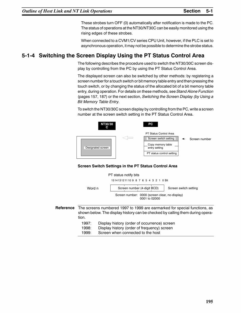
Reference
5-1SectionOutline of Host Link and NT Link Operations
195
These strobes turn OFF (0) automatically after notification is made to the PC.The status of operations at theNT30/NT30Ccanbe easilymonitored using therising edges of these strobes.
When connected to a CVM1/CV series CPUUnit, however, if the PLC is set toasynchronous operation, itmay not be possible to determine the strobe status.
5-1-4 Switching the Screen Display Using the PT Status Control AreaThe following describes the procedure used to switch the NT30/30C screen dis-play by controlling from the PC by using the PT Status Control Area.
The displayed screen can also be switched by other methods: by registering ascreennumber for a touch switch or bitmemory table entry and thenpressing thetouch switch, or by changing the status of the allocated bit of a bit memory tableentry, during operation. For details on thesemethods, seeStand Alone Function(pages 157, 187) or the next section, Switching the Screen Display (by Using aBit Memory Table Entry.
To switch theNT30/30Cscreendisplay by controlling from thePC,write a screennumber at the screen switch setting in the PT Status Control Area.
NT30/30C
PC
Designated screen
PT Status Control Area
Screen switch setting
PT status control setting
Screen number
Copy memory tableentry setting
Screen Switch Settings in the PT Status Control Area
151413121110 9 8 7 6 5 4 3 2 1 0 Bit
PT status notify bits
Word n Screen number (4-digit BCD) Screen switch setting
Screen number: 0000 (screen clear, no-display)0001 to 02000
The screens numbered 1997 to 1999 are earmarked for special functions, asshown below. The display history can be checked by calling them during opera-tion.1997: Display history (order of occurrence) screen1998: Display history (order of frequency) screen1999: Screen when connected to the host

5-1SectionOutline of Host Link and NT Link Operations
196
S Allocated Words
The PTStatus Control Area (PC to PT) can be allocated words in the followingPC areas.
f: Possible×: Impossible
Sym-bol C Series PC Alloca-
tion CVM1/CV Series PC Alloca-tion CS1 Series PC Alloca-
tion
DM DM Area f DM Area f DM Area f
CH IR Area f CIO Area f CIO Area f
TIM Timer Area × Timer × Timer ×CNT Counter Area × Counter Area × Counter Area ×HR HR Area f -- -- HR Area ×AR AR Area f Auxiliary Area × Auxiliary Area ×LR LR Area f -- -- -- --
The Auxiliary Area of CV series PC is used exclusively for special applications inthe system, and cannot be used for other application.
The range of respective area varies with the type of PC. Refer to the appendixPC Memory Map (page 291).
Procedure 1. Use theNT-series Support Tool to allocate thePTStatusControl Area (PC toPT) to the PC memory.
2. Program the PC to write the number of the displayed screen to the screenswitch setting word in the PT Status Control Area.
Use a 4-digit BCD (binary-coded decimal) value to set a screen number.
If a screen has been switched by operating the PT Status Control Area (PCto PT), the contents of the currently displayed screen word in the PT StatusNotify Area (PT to PC) also change.
S Startup Screen
When the NT30/30C starts up, it displays the screen whose screen number iswritten in the screen switch setting. The startup screen set with the NT-seriesSupport Tool is invalid.
S Screen Switching Timing
TheNT30/30C screen switcheswhen the contents of the screen switch settinghave changed. To re-specify the number of the currently specified screen, firstwrite the value 0000 to clear the screen before writing the appropriate screennumber.
S Use of the Screen Switching Strobe
Program the PC to read the number of the currently displayed screen and towrite the number to the screen switch setting word at the leading edge of thescreen switching strobe of the PT Status Notify Area. This programming en-ablesscreenswitchingbyusing the touchswitcheson theNT30/30Candelimi-nates repeated setting of the same screen number. If the screen switching isnot executed on the NT30/30C, the screen switching strobe does not need tobe checked.
For the screen switching strobe, refer to theNotifying theDisplayScreen to thePC (page 199).

5-1SectionOutline of Host Link and NT Link Operations
197
S Consecutive Screens and Overlapping Screens
Consecutive or overlapping screens can be displayed by designating the par-ent screen. If a child screen is designated, only the child screen is displayed.
For information on consecutive and overlapping screens, refer to the Classifi-cation of Screens (page 131).
Example of Display Screen Switching
This example operates the PC switch (bit) to switch the NT30/30C displayscreen.
S NT-series Support Tool Settings
Make the following settings with the NT-series Support Tool:
PT Status Control Area: IR 0100
PT Status Notify Area: IR 0110
Screen number to be created: Screen No. 2 and No. 3
S PC Ladder Program
Include the following in the PC ladder program:
@MOV(21)#0002100
00002
00003
11212
@MOV(21)#0003100
@MOV(21)110100
(1)Screen numberScreen switch setting word
(2)Screen numberScreen switch setting word
(3)Screen numberScreen switch setting word
Screen switch strobe flag
S Program Operation
(1) Screen #2 is displayed on the NT30/30C when IR/CIO 00002 turns ON.
(2) Screen #3 is displayed on the NT30/30C when IR/CIO 00003 turns ON.
(3) When the screen switch strobe flag turns ON, the number of the currentlydisplayed screen is read and written to the currently displayed screen wordin the PT Status Notify Area. In this case, the NT30/30C will not write thesame screen twice.
5-1-5 Switching the Screen Display Using a Bit Memory Table EntryThis section describes the actual procedure used to perform screen switchingunder the control of the PC by using bit memory table entries.
This function continually reads the allocated bits of the screen switching functionregardless ofwhich screen is currently displayed.Consequently, if the number ofscreens that could be switched to with this function is large, PT operations (suchas updating of memory table entries, touch switch response, lamp response)may be delayed.
One of two methods can be used to switch the screen display: registering ascreen number for a touch switch and pressing the touch switch during opera-

Reference
5-1SectionOutline of Host Link and NT Link Operations
198
tion, or writing the screen number into the PT Status Control Area. For details onthese methods, see Stand-alone Functions (page 157, 187) or Switching theScreen Display Using the PT Status Control Area (page 195).
To switch the screen displayed on the screen of the NT30/30C under the controlof thePC, the allocated bit of the bitmemory table entry inwhich the screen num-ber of the screen to be displayed is registered is set to 1 (ON).
NT30/30C
PC
Screen No.42displayed
Screen No.42Allocated bit (bit table entry 1)Bit table entry 1
←1 (ON)
The screens numbered 1997 to 1999 are earmarked for special functions, asshown below. The display history can be checked by calling them during opera-tion.1997: Display history (order of occurrence) screen1998: Display history (order of frequency) screen1999: Screen when connected to the host
S Allocated Words
The PT Status Notify Area (PT to PC) can be allocated words in the followingPC areas.
f: Possible×: Impossible
Sym-bol C Series PC Alloca-
tion CVM1/CV Series PC Alloca-tion CS1 Series PC Alloca-
tion
DM DM Area f DM Area f DM Area f
CH IR Area f CIO Area f CIO Area f
TIM Timer Area × Timer × Timer ×CNT Counter Area × Counter Area × Counter Area ×HR HR Area f -- -- HR Area ×AR AR Area f Auxiliary Area × Auxiliary Area ×LR LR Area f -- -- -- --
The Auxiliary Area of CV series PC is used exclusively for special applications inthe system, and cannot be used for other application.
The range of respective area varies with the type of PC. Refer to Appendix JPC Memory Map (page 291).
Procedure 1. Use the NT-series Support Tool to allocate the PT Status Notify Area (PT toPC) to the PC memory.
2. Program the PC to switch the allocated bit from OFF to ON and switch thescreen display. In cases such as that where a warning screen is to be dis-played when a particular bit is turned ON, programming is not required; it issufficient just to set the allocated bit.
S Screen Display Timing
The NT30/30C screen switches when the allocated bit of the bit memory tableentry changes from the0 (OFF) to1 (ON) status.However, thedisplay doesnotchange when the allocated bit returns from the 1 (ON) to the 0 (OFF) status.

5-1SectionOutline of Host Link and NT Link Operations
199
Example Application of Screen Switching
In this example, if the temperature in awater tank rises above theupper limit, a bitis turned ON, and the warning screen that corresponds to the bit is displayed.
S NT-series Support Tool Settings
The following settings are made using the NT-series Support Tool.
Bit memory table entry No. 0
Allocated bit 000100 (input bit that comes ON when the. . . . . . . . . .temperature of the water tank rises above theupper limit)
Function Screen switching (screen No. 1000). . . . . . . . . . . . . .
Created screen No. Screen No. 1000. . . .
Proc.4 Water Tank Temp.
OVERHEATING
Return
Urgent: Check the thermostat!
S PC Program
Ladder programming to control the NT30/30C is not required.
S Program Operation
When IR/CIO 001000 comes ON, the NT30/30C displays screen No. 1000.
5-1-6 Notification of Number of Currently Displayed Screen
The following describes the processing to ascertain the number of the currentlydisplayed screen of the NT30/30C.
This processing reads the data from the PC status notify area.
To indicate that the screen has switched, use the screen switch strobe flag.
To display the number of the currently displayed screen, use the currently dis-played screen word.
When the screen has switched, the NT30/30C notifies the following to PTStatusNotify Area (PT to PC) allocated to the PC.
Screen switch notification: Screen switch strobe flag of the PT status word
New screen number: Currently displayed screen word

5-1SectionOutline of Host Link and NT Link Operations
200
By reading the currently displayed screen word when the screen switch strobeflag has turned ON, the number of the currently displayed screen on theNT30/30C is displayed.
NT30/30C PC
Currentlydisplayedscreen
PT Status Notify Area
Currently displayed screen Screen numberContent upgrade memory table entry
PT status Screen switchstrobe flag
Currently Displayed Screen and PT Status in the PT Status Notify Area
151413121110 9 8 7 6 5 4 3 2 1 0 Bit
-- 0 -- -- -- 0 0 --
Wordm
15 14 13 12 11 10 9 8 7 Bit
Screen number (4-digit BCD)*
PT status notify bit PT status
* Screen number: 0001 to 2000
m+2
Screen switch strobe
Screen switch setting
0000
Use a 4-digit BCD (binary-coded decimal) value to set a screen number.
The screen switch strobe bit reverts to OFF (0) after this is notified to the PC.
S Allocated Words
The PT Status Notify Area (PT to PC) can be allocated words in the followingPC areas.
f: Possible×: Impossible
Sym-bol C Series PC Alloca-
tion CVM1/CV Series PC Alloca-tion CS1 Series PC Alloca-
tion
DM DM Area f DM Area f DM Area f
CH IR Area f CIO Area f CIO Area f
TIM Timer Area × Timer × Timer ×CNT Counter Area × Counter Area × Counter Area ×HR HR Area f -- -- HR Area ×AR AR Area f Auxiliary Area × Auxiliary Area ×LR LR Area f -- -- -- --
The Auxiliary Area of CV series PC is used exclusively for special applications inthe system, and cannot be used for other application.
The range of respective area varies with the type of PC. Refer Appendix J PCMemory Map (page 291).
Procedure 1. Use the NT-series Support Tool to allocate the PT Status Notify Area (PT toPC) to the PC memory.
2. Program the PC to read the currently displayed screen word in the in the PTStatus Notify Areawhen the screen switch strobe flag in the PTStatus NotifyArea has turned ON.

5-2SectionMemory Tables and Graphs
201
The contents of the currently displayed screen word are updated also by switch-ing the screen by pressing a touch switch on the NT30/30C.
For this function, refer to theStand-aloneFunction (pages157, 187) orSwitchingthe Screen DisplayUsing a Bit Memory Table Entry (page 197).
S Consecutive Screens and Overlapping Screens
Whena consecutive or overlapping screen is displayed, the number of thepar-ent screen is written to the currently displayed screen word.
For information on consecutive and overlapping screens, refer to the Classifi-cation of Screens (page 131).
Example of Reading the Number of Currently Display Screen
This example gives the PC program section that reads the screen number eachtime the screen is switched. In this example, thenumber of theprevious screen isalso stored.
S NT-series Support Tool Settings
Make the following settings with the NT-series Support Tool:
PT Status Notify Area: IR 0110
S PC Ladder Program
@MOV(21)DM0100DM0101
11212
@MOV(21)110
DM0100
(1)Word for storing the number ofthe previous screen
(2)Word for notifying the number of thecurrently displayed screenWord for storing a new screen number
Screen switchstrobe flag
S Program Operation
(1) When the NT30/30C screen display switches and the screen switch strobeflag (IR/CIO 11212) turns ON, the contents of DM0100 are transferred toDM0101. The number of the previously displayed screen is stored in word0101.
(2) The new screen number notified by theNT30/30C is read and transferred toDM0100. The number of the currently displayed screen is stored inDM0100.
5-2 Memory Tables and GraphsDisplaying Character String Memory Table Contents
Since the character stringmemory table can be allocated to words in the PC, thePC can write data to the character string memory table entries, and initial valuescan be set when creating the screen data.
During operation, automatic updating is performed to ensure that the currentlydisplayed NT30/30C character stringmemory table entry contents and PCwordcontents always match each other.

Reference
5-2SectionMemory Tables and Graphs
202
Thereare twomethods for accessing character stringmemory table entriesusedfor character string display, as follows:
- Direct specification (character stringdisplayproperty IndirectSpecificationset to OFF.)
- Indirect specification (character stringdisplayproperty IndirectSpecificationis set to ON.)
Only direct specification can be used as the access method for character stringmemory table entries used for character string settings.
S Direct Specification
Direct specification is a method of specification in which the contents of dis-playedmemory table entries are directly correlated with the contents of the al-located words.
Directspecification
Character stringmemory table entry 51
Allocated word(character string memorytable entry 51)
NT30/30C PC
a b c d 6 1 6 26 3 6 4
a b c dDM0100
S Indirect Specification
In indirect specification, even if the displayed data is a character string, the dis-play is correlated with a numeral memory table entry. The contents (numericalvalue) of this numeral memory table entry are regarded as a character stringmemory table entry number and the contents of the table entry with this num-ber are displayed.
A combined total 50 of numeral displays and character string displays can bespecified on one screen by using indirect specification.
Indirectspecification
Numeral memorytable entry 20
Allocated word(numeral memory table entry 20)
NT30/30C PC
a b c d 0 0 5 10 0 5 1DM0000
Character stringmemory table entry 51
Allocated word(character string memorytable entry 51)
6 1 6 26 3 6 4
a b c dDM0100
This specification method is a little complex, but it allows the display to bechangedmore easily according to the circumstances. In the example above, if1 were added to the contents ofmemory table entry 20 to give 52, the contentsof memory table entry 52 would be displayed instead.
Thememory table entries used for display can also be allocated to areas in thePC, so that the display can also be changed in response to changes in the datato be displayed (i.e., the contents of character string memory table entry 51 inthe example above).

5-2SectionMemory Tables and Graphs
203
However, in comparison with direct specification, indirect specification re-quires more time for processing.
Setting the Words of the Character String Memory Table
When creating the screen data by using the NT-series Support Tool, make thefollowing settings for each numbered character string:
S Initialization Setting
Set whether or not the PC words are initialized with the character stringmemory table initial value registered to the screendatamemorywhen themainpower supply is turned ON or reset.
S Number of Registration Words
Set the number of words within 20 words required for registering the characterstring data. One word can store two characters.
S Setting the Words for the Character String Memory Table Entries
The character stringmemory table entries can be allocated to the followingPCwords. Set the word type and the first word.
f: Possible×: Impossible
Sym-bol C Series PC Alloca-
tion CVM1/CV Series PC Alloca-tion CS1 Series PC Alloca-
tion
DM DM Area f DM Area f DM Area f
CH IR Area f CIO Area f CIO Area f
TIM Timer Area × Timer × Timer ×CNT Counter Area × Counter Area × Counter Area ×HR HR Area f -- -- HR Area ×AR AR Area f Auxiliary Area × Auxiliary Area ×LR LR Area f -- -- -- --
The Auxiliary Area of CV series PC is used exclusively for special applications inthe system, and cannot be used for other application.
The range of respective area varies with the type of PC. Refer to the appendixPC Memory Maps (page 291).
If the number of registration words x 2 (word setting window) set in memorytable (TBL EDIT) on the NT-series Support Tool is larger than the number ofcharacter digits (character string display setting window), the character stringmay be broken halfway.
Displaying Numeral Memory Table Contents
Since the numeralmemory table can be allocated towords in thePC, thePCcanwrite data to thenumeralmemory tableentries, and initial values canbesetwhencreating the screen data.
In addition, if a numeral memory table entry is correlated with a graph, the graphcan be displayed in accordance with the numeric value in the numeral memorytable entry.
During operation, automatic updating is performed to ensure that the currentlydisplayed NT30/30C numeral memory table entry contents and PC word con-tents always match each other.
There are twomethods for accessing numeralmemory table entries used for nu-meral display, as follows:

Reference
5-2SectionMemory Tables and Graphs
204
- Direct specification (numeral display property Indirect Specification is set toOFF)- Indirect specification (numeral display property Indirect Specification is set toON)
Only direct specification can be used as the access method for graphs and nu-meral settings.
S Direct Specification
Direct specification is a method of specification in which the contents of dis-playedmemory table entries are directly correlated with the contents of the al-located words.
Directspecification
Character stringmemory table entry 18
Allocated word(character stringmemory table entry 18)
NT30/30C PC
0 0 6 2 0 0 6 20 0 6 2DM0100
S Indirect specification
Indirect specification is a method whereby the contents (numeric value) of thespecified numeral memory table entry are taken as the number of a numeralmemory table entry, and the contents of the numeral memory table entry withthat number are displayed.
A combined total 50 of numeral displays and character string displays can bespecified on one screen by using indirect specification.
Indirectspecification
Numeral memorytable entry 18
Allocated word(numeral memorytable entry 18)
NT30/30C PC
7 7 7 7 0 0 6 20 0 6 2DM0100
Character stringmemory table entry 62
Allocated word(character stringmemory table entry 62)
7 7 7 77 7 7 7DM0200
This specification method is a little complex, but it allows the display to bechangedmore easily according to the circumstances. In the example above, if1 were added to the contents ofmemory table entry 18 to give 52, the contentsof memory table entry 63 would be displayed instead.
Thememory table entries used for display can also be allocated to areas in thePC, so that the display can also be changed in response to changes in the datato be displayed (i.e., the contents of character string memory table entry 62 inthe example above).
However, in comparison with direct specification, indirect specification re-quires more time for processing.

5-2SectionMemory Tables and Graphs
205
Setting the Words of the Numeral Memory Table
When creating the screen data by using the NT-series Support Tool, make thefollowing settings for each numbered numeral:
S Initialization setting
Set whether or not the PCwords are initialized with the numeral memory tableinitial value registered to the screen datamemorywhen themain power supplyis turned ON or reset.
S Number of registration words
Set the number of words within 2 words required for registering the numeraldata. One word can store up to 4 digits. Two words can store up to 8 digits.
S Setting the Words for the Numeral Memory Table Entries
The numeralmemory table entries can be allocated to the following PCwords.Set the word type and the first word.
f: Possible×: Impossible
Sym-bol C Series PC Alloca-
tion CVM1/CV Series PC Alloca-tion CS1 Series PC Alloca-
tion
DM DM Area f DM Area f DM Area f
CH IR Area f CIO Area f CIO Area f
TIM Timer Area 1 word Timer 1 word Timer 1 word
CNT Counter Area 1 word Counter Area 1 word Counter Area 1 word
HR HR Area f -- -- HR Area ×AR AR Area f Auxiliary Area × Auxiliary Area ×LR LR Area f -- -- -- --
The Auxiliary Area of CV series PC is used exclusively for special applications inthe system, and cannot be used for other application.
The range of respective area varies with the type of PC. Refer to the appendixPC Memory Maps (page 291).
5-2-1 Allocated Words and Display of the Memory TablesThis section explains the relationship between the contents of the allocatedwords of numeral/character string memory table entries and their display.
S Contents of Numeral Memory Table Entries
Stored as a Single Word
15 to 12 11 to 8 7 to 4 3 to 0 Bit
Digit 4 Digit 3 Digit 2 Digit 1
Example: 1234
15 to 12 11 to 8 7 to 4 3 to 0 Bit
1 2 3 4
Stored as a Double Words
Word 15 to12 11 to 8 7 to 4 3 to 0 Bit
Start Digit 4 Digit 3 Digit 2 Digit 1
Start+ 1 Digit 8 Digit 7 Digit 6 Digit 5

5-2SectionMemory Tables and Graphs
206
Example: 12345678
Word 15 to12 11 to 8 7 to 4 3 to 0 Bit
Start 5 6 7 8
Start+ 1 1 2 3 4
S Displaying Numeral Memory Table Entry
Numerals can be displayed in three different ways according to the contents ofthe numeral memory table entry, as mentioned below.
The most significant digit (digit 4 of a single word or digit 8 of a double word) isprocessed in different ways.
Hexadecimal display: All digits are handled as stored in the allo-cated words.
Decimal display without signs: If themost significant digit is F, it is handled as0, and the most significant digit other than Fand other digits are handled as stored in theallocated words.
Decimal display with signs: If themost significant digit is F, it is handled as-- (minus sign), and the most significant digitother than F and other digits are handled asstored in the allocated words.
Numeral Memory Table Entry Display Examples
- When the data are numeral data (0 to 9)
StartStart + 1
Decimal without sign 123456Decimal with sign --123456Hexadecimal F0123456
3 4 5 6
F 0 1 2
- When the data contain characters (A to F)
StartStart + 1
Decimal without sign 123B56Decimal with sign --123B56Hexadecimal F0123B56
3 B 5 6
F 0 1 2
If the hexadecimal data (A to F) are stored when the decimal display has beenset, the alphabets are displayed.
If the number of display digits has been set to be smaller than the maximumnumber of digits of the registration words (4 digits for 1 word; 8 digits for 2words), the contents of the allocated words are not displayed and : symbolswill be displayed at all digits.
If the most significant digit is F when decimal with signs has been set, the nu-meral is handled as a negative number. The maximum number of digits of thenegative number becomes smaller than that of the positive number by 1 digit.
The actual displaywill vary according to the zero suppress setting and decimalfraction setting as well as the contents mentioned above. Refer to the NT-se-ries Support Tool for Windows Operation Manual (V061).
S Contents of the Character String Memory Table Entry
A character string is stored in the allocated words beginning with the first wordin normal-size characters or marks.

5-2SectionMemory Tables and Graphs
207
Two normal-size characters or one mark is stored in one word. One memorytable entry can store up to 20 words (40 characters).
Start Start + 1 Start + 19
Code 1 Code 2 Code 3 Code 4 Code39 Code40
ASCII control characters (00 to 1FH) are displayed on the screen as a spacecharacter (20H).
Character String Memory Table Entry Display Example
To display the characters in order, allocate the characters as follows.
A = 41H, B = 42H Start
4 7 4 8
4 1 4 2
4 3 4 4
4 5 4 6 ABCDEFGH
G = 47H, H = 48H Start + 3
E = 45H, F = 46H Start + 2
C = 43H, D = 44H Start + 1
5-2-2 Changing Displayed Numerals or Character Strings, DirectSpecification
The following describes the procedure to change displayed numerals or charac-ter strings by changing the contents of the allocated words.
If using indirect specification, refer toChanging Displayed Numerals or Charac-ter Strings, Indirect Specification (page 209).
Numerals and character strings can also be changed by copying betweenmemory table entries: see Copying Memory Table Entries (page 212).
To change the numerals or character strings displayed on the NT30/30C, makechangeswith the numeral or character stringmemory table entry. Tomake chan-ges with the numeral or character string memory table entry of the NT30/30C,change the contents of words by the PC.
Allocated word (character string memory table entry)
PC
Numeral memorytable entry 1
Character stringmemory tableentry 4
StartStart+1
StartStart+1Start+2
Allocated word(numeral table entry)
12345678
abcdefabcdef
12345678
NT30/30C
When it is necessary todisplay changingdata suchasmonitoreddataofwords inthe PC, use the numeral and character stringmemory tables. Thismust be usedto change the display contents (contents of memory table entries and words).
Procedure 1. Use the NT-series Support Tool to allocate the numeral and character stringmemory tables to the PC memory.
2. Register the memory table entries for the numerals and character strings tobe displayed when creating the screen data by using the NT-series SupportTool.
To display a character string, use a character display and specify the charac-ter string memory table entry by using the NT-series Support Tool.
To display numerals, use anumeral display and specify the numeralmemorytable entry by using the NT-series Support Tool.

5-2SectionMemory Tables and Graphs
208
3. Program thePC towrite the contents of numerals and character strings to bedisplayed on the NT30/30C to the PC words.
S Important Points when Writing a Character String
If a character string to be written is smaller than allocated word x 2, fill up thevacant stop with spaces (20H). If unnecessary characters are left in the area,the character string will not be displayed correctly.
If the character font for character strings displayed on the NT30/30C screen isset as half size and a normal-size character string is written after displaying a2-byte code (mark), part of the mark will remain displayed, as shown below.
A B C D Ea b c d e f g h i j
In this case, first write a 2-byte code (EB9F toEBDE) for which nothing is regis-tered, then write a normal-size character string.
Application Example of the Numeral Memory Table Entries Allocated to the PC Words
This example gives the procedure to directly display the contents of the wordsallocatedas thenumeralmemory tableentries in thePCmemory. TheNT30/30Cscreen display will change as the contents of the PC word change.
S NT-series Support Tool Settings
Allocate the memory as shown below by using the NT-series Support Tool.
Numeral memory table entry No. 1: DM0000 (registration word: 2)
Numeral memory table entry No. 2: DM0002 (registration word: 1)
Screen numbers to be created: No. 1 and No. 2
Numeralmemory tableentry No. 1(8-digit input)
Numeralmemory tableentry No. 2(4-digit input)
Line 1
Qty. 15289 unit
Defects 23 unit

5-2SectionMemory Tables and Graphs
209
S PC Ladder Program
Include the following in the PC ladder program.
(2)Word for most significant 4 digits of No. 1
INC(38)DM0000
00100
INC(38)DM0001
(1)Word for least significant 4 digits of No. 1
@INC(38)DM0002
(3)Word for No. 2
25506 (=)
00001
DIFU(13)00100
25502 (1 second clock)
S Program Operation
(1) The contents of word DM0000 are incremented by 1 each second. The val-ue displayed on the NT30/30C in numeral table entry No. 1 increases by 1each second.
(2) When the counter in (1) above causes an increase in the most significantdigits, the contents ofwordDM0001are incrementedby1each second.Thevalue displayed on theNT30/30C in numeralmemory table entryNo. 1mostsignificant digits increases by 1.
(3) When IR/CIO 00001 turns ON, the contents of DM0002 are incremented by1. The value displayed on theNT30/30C in numeralmemory table entry No.2 increases by 1.
5-2-3 Changing Displayed Numerals or Character Strings, IndirectSpecification
The following describes the procedure to change displayed numerals or charac-ter strings by changing the contents of the allocated words.
If using direct specification, refer toChanging Displayed Numerals or CharacterStrings, Direct Specification (page 207).
Numerals and character strings can also be changed by copying betweenmemory table entries. See Copying Memory Table Entries (page 212).
The following describes the procedure to change displayed numerals or charac-ter strings indirectly by specifying a numeral/memory table entry. The contents ofthe specified numeral memory table entry (39 in the following example case) isregarded as the memory table entry number used for display.
Either of the following two methods can be used to change the contents of thedisplay.
(1) Changing the memory table entry number to be displayed(To change the contents of numeral memory table entry 41, in the followingexample case)
(2) Changing the contents of the memory table entry used for display(To change the contents of character string memory table entry 39, in thefollowing example case)

5-2SectionMemory Tables and Graphs
210
In this section, the procedure for changing the display contents by usingmethod(1) is explained.
Method (2) involves changing the contents of the allocated table entry. For de-tails, refer to the sections on memory table entry copy (page 212) and changingdisplayed numerals or character strings (direct specification) (page 207).
PC
AaBb
AaBb
Moji
0039 0 0 3 9 ←0039
Allocated word (numeraltable entry 41)Indirect numeral table entry 41
Character string memory table entry 39
Character string memory table entry 40
NT30/30C
This method is convenient when switching the display at the same location, forexample when monitoring a series of words, or when using unique codes tospecify individual character strings, etc.
Procedure 1. Set the PC area for the numeral memory table entries to be used for indirectspecification of numeral/character display using theNT-series Support Tool.
2. When creating the screen data with the NT-series Support Tool, register forthescreen thenumeralmemory tableentryaccessedusingan indirect speci-fication. Set “Indrct” for “Ref way”.
For a character string, specify the numeral memory table entry by using thecharacter display function of the NT-series Support Tool.
For numerical values, specify the numeral memory table entry by using thenumeral display function of the NT-series Support Tool.
3. Using the table edit function of the NT-series Support Tool, write the data tobedisplayed to thememory tableentry that is used for display.Useanumeralmemory table entry to display numerals and use a character string memorytable entry to display character strings.
4. Program the PC to change the contents of the word allocated to the numeralmemory table entry that is used in indirect specification.
S Important Points when Writing Memory Table Entry Numbers
When writing the number of the memory table entry whose contents are to bedisplayed to the numeral memory table entry to be accessed using an indirectspecification, always specify this number in BCD format. Also make sure thatyou do not specify a number outside the range ofmemory table entry numbersthat actually exist (for example by specifying 0500when the number of charac-ter string memory table entries is set to 256).
If the contents of thememory table entry used for indirect specification arewrit-ten in hexadecimal format, or if the specifiedmemory table entry number is out-side the available range, the display will not be updated.
S Important Points when Writing Character Strings
The important points when displaying character strings are the same as thosethat apply for indirect specification. See the Important Points when WritingCharacter Strings Using Direct Specification (page 207).

Line 1
NT610G
Display of character string (specification of numeralmemory table entry number 51 in indirect specification)
5-2SectionMemory Tables and Graphs
211
Example of Changing a Character String in Indirect Specification
An example in which the character strings being displayed are changed by ad-ding the contents of the word allocated to the numeral memory table entry that isused in indirect specification is given below.
S NT-series Support Tool Settings
Perform the following setting with the NT-series Support Tool.
Numeral memory table entry No. 51:DM0000 (registration word: 1 word)
Character string memory table entry No. 100:NT610G (6 digits).
Character string memory table entry No. 101:NT610C (6 digits).
Character string memory table entry No. 102:NT30 (6 digits)
Character string memory table entry No. 103:NT30C (6 digits)
Contents to be registered for the screen: Numeral memory table entry No. 51
S PC Program
Include the following in the PC ladder program.
@INC(38)DM0000
00100(1)
Numeral memory table entry numberused for indirect specification
@INC(39)DM0000
00101(2)
Numeral memory table entry numberused for indirect specification
S Program Operation
(1) Each time IR/CIO 00100 comes ON, the display on the NT30/30C chan-ges to the next item in the following sequence.
NT610G→ NT610C→ NT30→ NT30C
(2) Each time IR/CIO 00101 comesON, the display on the PT changes to thenext item in the following sequence.
NT30C → NT30 → NT610C → NT610G
In this example, the contents of numeral memory table entry 51, which is ac-cessed using indirect specification, are not checked. When actually using theprogram, make sure that the contents of numeral table No. 51 are not outsidethe range 0100 to 0103.

5-2SectionMemory Tables and Graphs
212
5-2-4 Copying Memory Table Entries
The following describes the procedure to change displayed numerals or charac-ter strings by copying the contents of a memory table entry.
Numeralsandcharacter stringscanbechangedalsobychanging thecontentsoftheallocatedwords.Refer toChangingDisplayedNumerals orCharacter strings(pages 207, 209) explained before.
To change the numerals or character strings displayed on the NT30/30C, copythe data between the numeral or character string memory table entries by usingthe copy memory table entry setting of the PT Status Control Area.
NT30/30C PC
Memory tablecopy source
Copy destination(for display)
PT status control areaScreen switch setting
PT status control setting
Copy source number
Copy destinationnumber
AA
A
Copy memory tablesetting
Write a memory table entry number etc. to the copy memory table entry settingarea in the PT Status Control Area in the PC memory. Data will be copied be-tween the memory table entries in the NT30/30C and the displayed value willchange accordingly.
This procedure is convenient to switch predetermined values or characterstrings according to the situation. By preparing several units of contents, variouscontents can be displayed by switching them to suit the situation.
Copy Memory Table Entry Setting in the PT Status Control Area
15 14 13 12 11 10 9 8 7 6 5 4 3 2 1 0 BitWordn+1 Copy memory
table entrysettingn+2
Copy type
0 Source memory table entry # (3-digit BCD)
Destination memory table entry # (3-digit BCD)
Copy type:
0: Copy between the character string memory table entries1: Copy between the numeral memory table entries1: 2 to F (nothing happens)
Copy source and destination memory table entry numbers:
Character string memory table entries: 000 to 999 (Numbers 256 to999 are read-only memory table entries. They cannot be used ascopy destinations. In addition, depending on the setting made in thesystemmemory settings of theNT-series Support Tool, it may not bepossible to use numbers 256 through 999.
Numeral memory entries: 000 to 999 (Depending on the settingmade in System under PT Configuration (System Memory with theDOSversion) of theNT-series Support Tool, itmay not be possible touse numbers 512 through 999).

5-2SectionMemory Tables and Graphs
213
S Allocated Words
The PT Status Control Area can be allocated to the following PC areas:
f: Possible×: Impossible
Sym-bol C Series PC Alloca-
tion CVM1/CV Series PC Alloca-tion CS1 Series PC Alloca-
tion
DM DM Area f DM Area f DM Area f
CH IR Area f CIO Area f CIO Area f
TIM Timer Area × Timer × Timer ×CNT Counter Area × Counter Area × Counter Area ×HR HR Area f -- -- HR Area ×AR AR Area f Auxiliary Area × Auxiliary Area ×LR LR Area f -- -- -- --
The Auxiliary Area of CV series PC is used exclusively for special applications inthe system, and cannot be used for other application.
The range of respective area varies with the type of PC. Refer to Appendix PCMemory Map (page 291).
Procedure 1. Use theNT-series Support Tool to allocate thePTStatusControl Area (PC toPT) to the PC memory.
2. Register the memory table entries for the numerals and character strings tobe displayed when creating the screen data by using the NT-series SupportTool.
To display a character string, use a character display and specify the charac-ter string memory table entry by using the NT-series Support Tool.
To display numerals, use anumeral display and specify the numeralmemorytable entry by using the NT-series Support Tool.
3. Set the copy source data to thememory table entrywhen creating the screendata by using the NT-series Support Tool.
Use the table edit function.
4. Program the PC to write the copy type, copy destination memory table entrynumber, and copy source memory table entry number to the copy memorytable entry setting word in the PT Status Control Area.
S Order for writing to the PT Status Control Area (PC to PT)
First write the copy destinationmemory table entry number, and then, write thecopy source memory table entry number to the PT Status Control Area (PC toPT).
TheNT30/30C reads thearea sometimeswhen thePC iswriting the settings. Ifthe copy source memory table entry number has been written first and ischanged, unexpected memory table entry may possibly be changed.
S Allocated Words that the NT30/30C Reads
The NT30/30C reads the allocated words in the PC for the memory table en-tries that need to be displayed. If the copy source memory table entry is allo-cated to a PC word, it may sometimes be used at the initialization only.
S Use of the Copy Type
Copywill not be executedwhen the copy type is other than 0 or 1. Thememorytable entry copy is executed only when the contents of the area are changed.

Line 1
Normal
Character-string memory table No. 4
5-2SectionMemory Tables and Graphs
214
To repeat copying of the same copy source and same copy destination, write avalue other than 0 or 1 for the copy type, and then, write a correct value again.
S Copying a Numeral Memory Table Entry
If the displaymethod or the number of registeredwords include discrepancies,a numeral memory table entry may not be copied and displayed correctly.
Application Example of Copying of a Character String Memory Table Entry
This example gives a PC program section to switch the character string displayon the screenbyusing thememory table entry copyoperationas the allocatedbitis turned ON and OFF.
S NT-series Support Tool Settings
Allocate the memory as shown below by using the NT-series Support Tool.
PT Status Control Area allocation: IR/CIO 0100
Contents registered to the screen: Character string display (character stringmemory table entry No. 4)
Character string memory table entry settings
No. Contents Number ofCharacter Digits
4 Normal 6 digits
10 Error 6 digits
11 Normal 6 digits
S PC Program
Include the following in the PC ladder program.
@MOV(21)#0004
09000
@MOV(21)#0010
(1)Copy type, copy destination memory table entryNo.Copy destination word
Copy source memory table entry No.Copy source word
@MOV(21)#0004
09000
@MOV(21)#0011
(2)Copy type, copy destination memory table entryNo.Copy destination word
Copy source memory table entry No.Copy source word
Error flag
Error flag
101
102
101
102
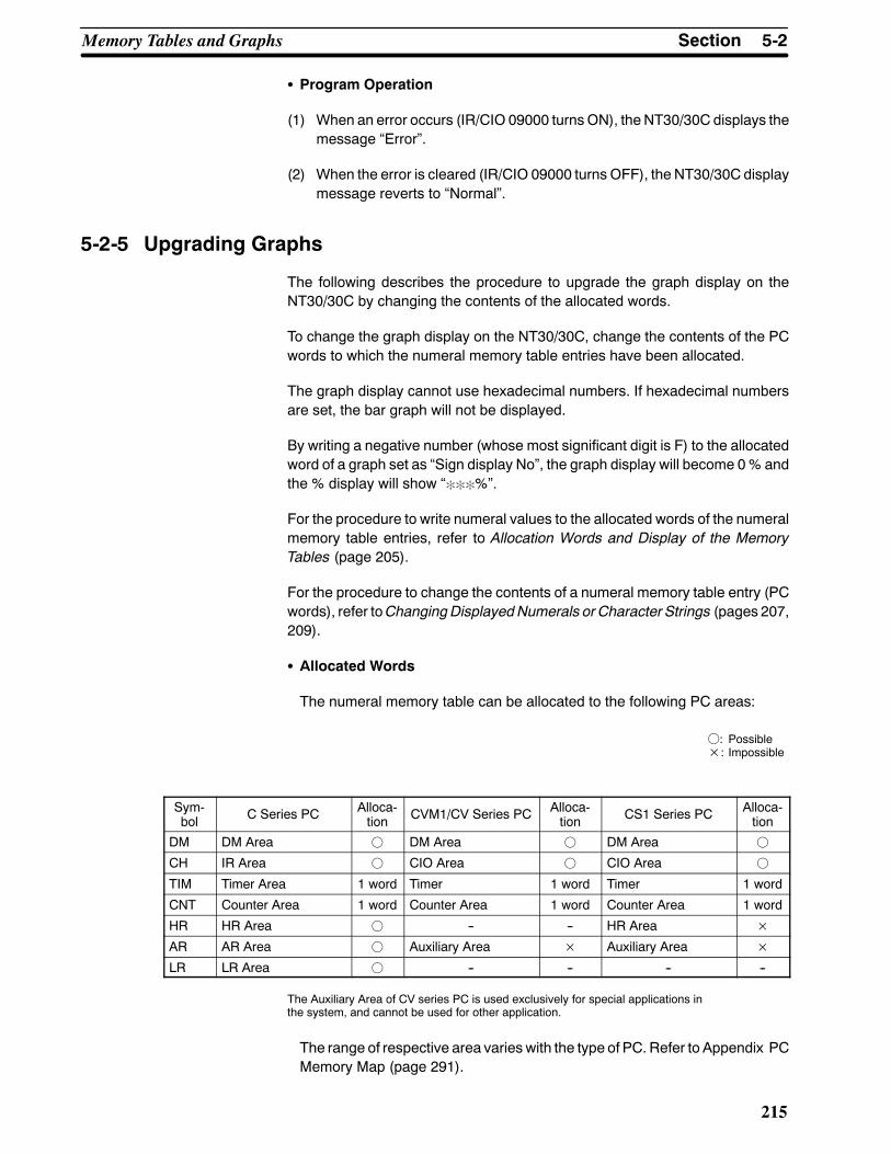
5-2SectionMemory Tables and Graphs
215
S Program Operation
(1) When an error occurs (IR/CIO 09000 turnsON), the NT30/30C displays themessage “Error”.
(2) When the error is cleared (IR/CIO 09000 turns OFF), the NT30/30C displaymessage reverts to “Normal”.
5-2-5 Upgrading Graphs
The following describes the procedure to upgrade the graph display on theNT30/30C by changing the contents of the allocated words.
To change the graph display on the NT30/30C, change the contents of the PCwords to which the numeral memory table entries have been allocated.
The graph display cannot use hexadecimal numbers. If hexadecimal numbersare set, the bar graph will not be displayed.
By writing a negative number (whose most significant digit is F) to the allocatedword of a graph set as “Sign display No”, the graph display will become 0% andthe % display will show “:::%”.
For the procedure to write numeral values to the allocated words of the numeralmemory table entries, refer to Allocation Words and Display of the MemoryTables (page 205).
For the procedure to change the contents of a numeral memory table entry (PCwords), refer toChangingDisplayedNumerals or Character Strings (pages 207,209).
S Allocated Words
The numeral memory table can be allocated to the following PC areas:
f: Possible×: Impossible
Sym-bol C Series PC Alloca-
tion CVM1/CV Series PC Alloca-tion CS1 Series PC Alloca-
tion
DM DM Area f DM Area f DM Area f
CH IR Area f CIO Area f CIO Area f
TIM Timer Area 1 word Timer 1 word Timer 1 word
CNT Counter Area 1 word Counter Area 1 word Counter Area 1 word
HR HR Area f -- -- HR Area ×AR AR Area f Auxiliary Area × Auxiliary Area ×LR LR Area f -- -- -- --
The Auxiliary Area of CV series PC is used exclusively for special applications inthe system, and cannot be used for other application.
The range of respective area varies with the type of PC. Refer to Appendix PCMemory Map (page 291).

5-3SectionLamps and Touch Switches
216
5-3 Lamps and Touch Switches
5-3-1 Allocated Bits and Display of LampsLamps are controlled by allocating them to the PC bits. Set the area and bit num-ber.
S Available Allocation Bits
The lamps can be allocated to the following PC areas:
f: Possible×: Impossible
Sym-bol C Series PC Alloca-
tion CVM1/CV Series PC Alloca-tion CS1 Series PC Alloca-
tion
DM DM Area f DM Area f DM Area f
CH IR Area f CIO Area f CIO Area f
TIM Timer Area × Timer × Timer ×CNT Counter Area × Counter Area × Counter Area ×HR HR Area f -- -- HR Area ×AR AR Area f Auxiliary Area × Auxiliary Area ×LR LR Area f -- -- -- --
The Auxiliary Area of CV series PC is used exclusively for special applications inthe system, and cannot be used for other application.
The range of respective area varies with the type of PC. Refer to the appendixPC Memory Maps (page 291).
Toset thedatamemory (DM), specify thewordnumberand then thebit number(00 to 15).
5-3-2 Turning ON and OFF LampsThe following describes the procedure to change the lamp display status on theNT30/30C by changing the contents of the allocated bits.
To change the lamp display status on the NT30/30C, turn ON and OFF the lampcontrol bit allocated in the PC.
NT30/30C PC
Lamp No. 1 Lamp No. 2
Unlit
Allocated bit (Lamp No. 1)
Allocated bit (Lamp No. 2)Lit
1
2 0 (OFF)
1 (ON)
The lamp control bit indicates the lamp status as follows:
0 (OFF): Unlit1 (ON): Lit (reverse display) or flashing
Procedure 1. Use the NT-series Support Tool to set the PC memory area where the lampcontrol bit is to be allocated to.
2. Register the lamps to the screen when creating the screen data by using theNT-series Support Tool.
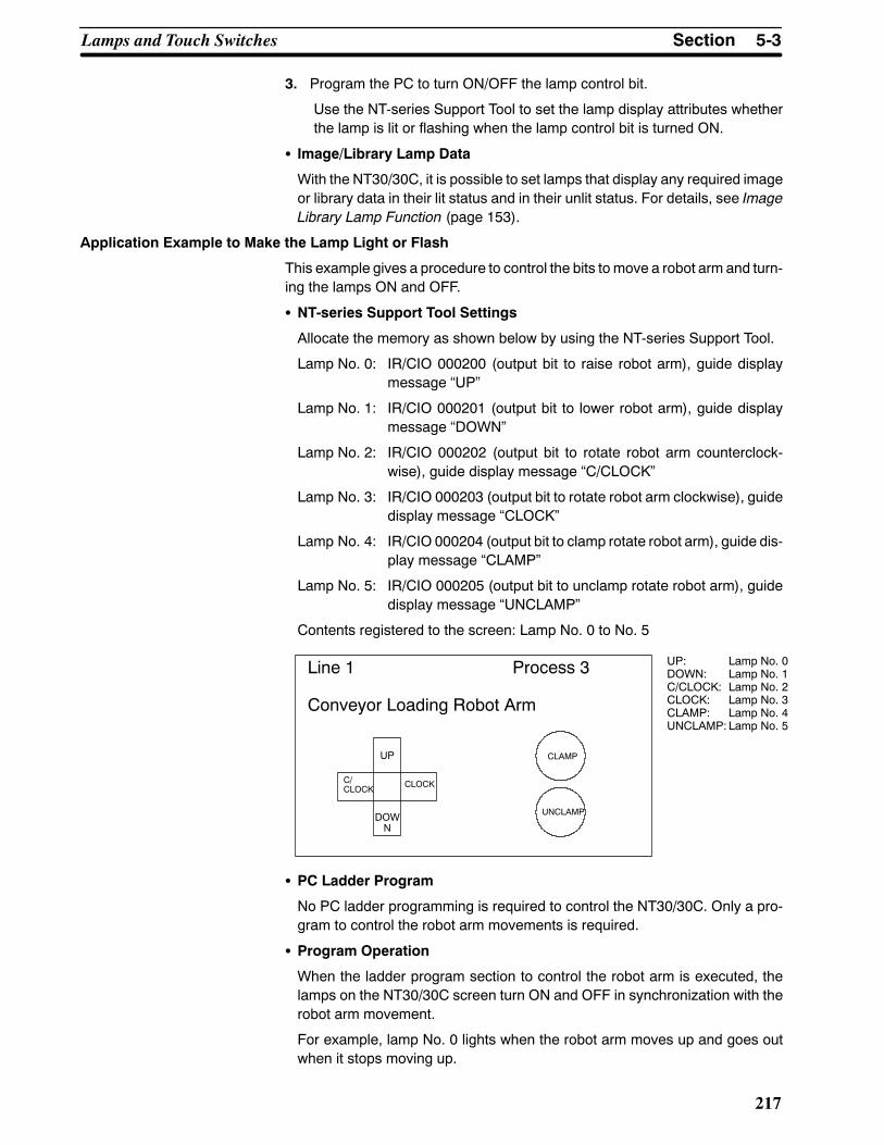
5-3SectionLamps and Touch Switches
217
3. Program the PC to turn ON/OFF the lamp control bit.
Use the NT-series Support Tool to set the lamp display attributes whetherthe lamp is lit or flashing when the lamp control bit is turned ON.
S Image/Library Lamp Data
With the NT30/30C, it is possible to set lamps that display any required imageor library data in their lit status and in their unlit status. For details, see ImageLibrary Lamp Function (page 153).
Application Example to Make the Lamp Light or Flash
This example gives a procedure to control the bits to move a robot arm and turn-ing the lamps ON and OFF.
S NT-series Support Tool Settings
Allocate the memory as shown below by using the NT-series Support Tool.
Lamp No. 0: IR/CIO 000200 (output bit to raise robot arm), guide displaymessage “UP”
Lamp No. 1: IR/CIO 000201 (output bit to lower robot arm), guide displaymessage “DOWN”
Lamp No. 2: IR/CIO 000202 (output bit to rotate robot arm counterclock-wise), guide display message “C/CLOCK”
Lamp No. 3: IR/CIO 000203 (output bit to rotate robot arm clockwise), guidedisplay message “CLOCK”
Lamp No. 4: IR/CIO 000204 (output bit to clamp rotate robot arm), guide dis-play message “CLAMP”
Lamp No. 5: IR/CIO 000205 (output bit to unclamp rotate robot arm), guidedisplay message “UNCLAMP”
Contents registered to the screen: Lamp No. 0 to No. 5
Line 1 Process 3
Conveyor Loading Robot Arm
UP: Lamp No. 0DOWN: Lamp No. 1C/CLOCK: Lamp No. 2CLOCK: Lamp No. 3CLAMP: Lamp No. 4UNCLAMP: Lamp No. 5
C/CLOCK CLOCK
DOWN
UP CLAMP
UNCLAMP
S PC Ladder Program
No PC ladder programming is required to control the NT30/30C. Only a pro-gram to control the robot arm movements is required.
S Program Operation
When the ladder program section to control the robot arm is executed, thelamps on the NT30/30C screen turn ON and OFF in synchronization with therobot arm movement.
For example, lamp No. 0 lights when the robot arm moves up and goes outwhen it stops moving up.
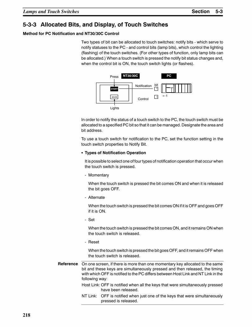
Reference
5-3SectionLamps and Touch Switches
218
5-3-3 Allocated Bits, and Display, of Touch SwitchesMethod for PC Notification and NT30/30C Control
Two types of bit can be allocated to touch switches: notify bits - which serve tonotify statuses to the PC - and control bits (lamp bits), which control the lighting(flashing) of the touch switches. (For other types of function, only lamp bits canbe allocated.) When a touch switch is pressed the notify bit status changes and,when the control bit is ON, the touch switch lights (or flashes).
START
Press
bitNotification
Lights
Control
NT30/30C PC
abcde
1
1 ←1
In order to notify the status of a touch switch to the PC, the touch switch must beallocated to a specified PCbit so that it can bemanaged. Designate the area andbit address.
To use a touch switch for notification to the PC, set the function setting in thetouch switch properties to Notify Bit.
S Types of Notification Operation
It is possible to select oneof four typesof notificationoperation that occurwhenthe touch switch is pressed.
- Momentary
When the touch switch is pressed the bit comes ON and when it is releasedthe bit goes OFF.
- Alternate
When the touch switch is pressed the bit comesON if it isOFFand goesOFFif it is ON.
- Set
When the touch switch is pressed the bit comesON, and it remainsONwhenthe touch switch is released.
- Reset
When the touch switch is pressed the bit goesOFF, and it remainsOFFwhenthe touch switch is released.
On one screen, if there is more than one momentary key allocated to the samebit and these keys are simultaneously pressed and then released, the timingwithwhichOFF is notified to the PCdiffers betweenHost Link andNTLink in thefollowing way:Host Link: OFF is notified when all the keys that were simultaneously pressed
have been released.NT Link: OFF is notified when just one of the keys that were simultaneously
pressed is released.

5-3SectionLamps and Touch Switches
219
S Important Points Relating to Notification Operations
Details on touch switch notification operations are listed below.
Type of notificationoperation
When using Host LinkWhen using NT link (DM
area)
When using NT link(other than DM area)
Momentary(1) Notification in word units
(all other bits in the wordare OFF)
(3) Notification in bit units
AlternateSetReset
(2) Notification in word units(note that the word con-tents are read on displayand notification is basedon these contents)
(4) Notification in bit units
When using touch switch input notification, note the following points.
- In the case of (1) in the table, the other bits in the sameword are turnedOFFby notification.
- In the case of (2) in the table, since notification is executed on the basis of thecontents of thewordbeforedisplay, theotherbits in thewordarenotoverwrit-ten. However, if the contents of the word are changed at the PC during dis-play, they will be rewritten based on the contents before display.
- If the screen is switched while amomentary key is pressed, the touch switchitself will disappear and theOFF status will be notified to the PC. Thismeansthat, in the case of (1) in the table, all the bits in thewordwill be set to theOFFstatus.
- When using the Host Link, or when using the NT link with the DM area, thenotification operation is different for themomentary type and the other types,and they should not both be specified in the same word.
In the case of (3) and (4), notification has no effect on the other bits in theword.
S Possible Bit Allocations
Notify bits and control bits for touch switches can be allocated to the areas ofthe PC memory listed in the following table.
f: Possible×: Impossible
Sym-bol C Series PC Alloca-
tion CVM1/CV Series PC Alloca-tion CS1 Series PC Alloca-
tion
DM DM Area f DM Area f DM Area f
CH IR Area f CIO Area f CIO Area f
TIM Timer Area × Timer × Timer ×CNT Counter Area × Counter Area × Counter Area ×HR HR Area f -- -- HR Area ×AR AR Area f Auxiliary Area × Auxiliary Area ×LR LR Area f -- -- -- --
The Auxiliary Area of CV series PC is used exclusively for special applications inthe system, and cannot be used for other application.
The range of each memory area differs according to the PC type. See the ap-pendix PC Memory Maps (page 291).
Whenmaking a datamemory (DM) specification, specify the bit number (00 to15) following the word number.

5-3SectionLamps and Touch Switches
220
5-3-4 Touch Switch StatusThis section describes how to change the statuses of allocated bits and therebythe statuses of the touch switches displayed by the NT30/30C.
The statuses of touch switches displayed by the NT30/30C are changed byswitching the control bits allocated in the PC memory ON and OFF.
NT30/30C PC
Lit
1 1 (ON)
Allocated bit (touch switch No. 1)
Touch switch 1
The status of the lamp bit reflects the touch switch status, as follows:
0 (OFF): Unlit
1 (ON): Lit (inverse display) or flashing
Procedure 1. Use the NT-series Support Tool to allocate the touch switch lamp bits to thePC memory.
2. Whencreating the screendata using theNT-seriesSupport Tool, register thetouch switch for a screen.
3. Program the PC to switch the lamp bit of the touch switch ON and OFF.
Set whether a touch switch will be continuously lit or blink when its bit hasbeen turned ON by setting the NT-series Support Tool touch switch displayattributes.
5-3-5 Notifying the PC that a Switch Has Been PressedThis section describes how the status of a touch switch (whether it has beenpressed or not) is accessed.
With the NT30/30C, when a touch switch is pressed, the notify bit allocated tothat touch switch in the PC memory is automatically notified.
Touch switch 1
Allocated notify bit (touch switch No. 1)
NT30/30C PC
1
Depending on the set operation type, the status of the allocated bit for touchswitch status notification will be controlled in tone of the following ways:
Momentary: 0 (OFF) Not pressed. .1 (ON) Pressed. . .
Alternate: The allocated bit is switches to 1 (ON) if currently 0, and to 0(OFF) if currently 1.
Set: The allocated notify bit is switched to 1 (ON).
Reset: The allocated notify bit is switched to 0 (OFF).

5-3SectionLamps and Touch Switches
221
In order to determine the status of a touch switch, the status of the touch switchnotification bit allocated to it is determined.
The touch switch notify bits can be allocated to the following areas of the PCmemory.
f: Possible×: Impossible
Sym-bol C Series PC Alloca-
tion CVM1/CV Series PC Alloca-tion CS1 Series PC Alloca-
tion
DM DM Area f DM Area f DM Area f
CH IR Area f CIO Area f CIO Area f
TIM Timer Area × Timer × Timer ×CNT Counter Area × Counter Area × Counter Area ×HR HR Area f -- -- HR Area ×AR AR Area f Auxiliary Area × Auxiliary Area ×LR LR Area f -- -- -- --
The Auxiliary Area of CV series PC is used exclusively for special applications inthe system, and cannot be used for other application.
The range of eachmemory area differs according to thePC type.See the appen-dix PC Memory Maps (page 291).
When making a data memory (DM) specification, specify the bit number (00 to15) following the word number.
Procedure 1. Use the NT-series Support Tool to allocate the touch switch notify bits to thePC memory.
2. Whencreating the screendata using theNT-seriesSupport Tool, register thetouch switch for a screen.
3. Program the PC to switch the notify bit of the touch switch ON and OFF.
S Important Points when Accessing Touch Switch Statuses
Details on touch switch notification operations are listed below.
Type of notificationoperation
When using Host LinkWhen using NT link (DM
area)
When using NT link(other than DM area)
Momentary(1) Notification in word units
(all other bits in the wordare OFF)
(3) Notification in bit units
AlternateSetReset
(2) Notification in word units(note that the word con-tents are read on displayand notification is basedon these contents)
(4) Notification in bit units
When using touch switch input notification, note the following points.

Reference
5-3SectionLamps and Touch Switches
222
- In the case of (1) in the table, the other bits in the sameword are turnedOFFby notification.
Bits other than notifybits are set to 0(OFF).
0 1 0 1 0 0 01
15 14 01 15 14 01Bit Bit
Press thetouch switch
Touch switchnotify bit
In the case of (2) in the table, since notification is executed on the basis of thecontents of thewordbeforedisplay, theotherbits in thewordarenotoverwrit-ten. However, if the contents of the word are changed at the PC during dis-play, they will be rewritten based on the contents before display.
- If the screen is switched while amomentary key is pressed, the touch switchitself will disappear and theOFF status will be notified to the PC. Thismeansthat, in the case of (1) in the table, all the bits in thewordwill be set to theOFFstatus.
- When using the Host Link, or when using the NT link with the DM area, thenotification operation is different for themomentary type and the other types,and they should not both be specified in the same word.
In the case of (3) and (4), notification has no effect on the other bits in theword.
In the case of (1), even bits whose status is held by self-holding operation or bythe KEEP instructionwill be turnedOFF. In order to avoid this, allocate a bit froman area other than the DM Area, even when communicating via NT Link.
Application Example This example uses the touch switches as normal switches (bits) in order to usethe NT30/30C as an operating panel.

Line 1
Touch switch No. 11
RUN
Touch switch No. 10
STOP
5-3SectionLamps and Touch Switches
223
S NT-series Support Tool Settings
Make the following settings using the NT-series Support Tool.
Touch switch No. 10:
Function: Notify Bit
Shape: 3-D
Lamp attributes: Light
Control bit: IR/CIO 05000 (Run flag) ... Guide message: RUN
Notify bit: IR/CIO 06000
Touch switch No. 11:
Function: Notify Bit
Shape: 3-D
Lamp attributes: Light
Control bit: IR/CIO 05001 (Stop flag) ... Guide message: STOP
Notify bit: IR/CIO 06001
Data registered for the screen: touch switch No. 10, touch switch No. 11
S PC Program
Include the following in the ladder program.
11212
06001
05001
06000
05000
06001
0600005001
05000
1 scan ON↓
Touch switch No. 10 notify bit↓
Stop flag(touch switch No. 11 lamp bit)
Touch switch No. 10 notify bit↓
Run flag(touch switch No. 10 lamp bit)
← Touch switch No. 11 notify bit
↑Touch switch No. 11 notify bit

5-4SectionNumeral and Character String Setting
224
S Program Operation
The operation when the program is executed is presented below.
Execute program
Press Run touchswitch.
Press Stop touch switch.
Stop flag: 1 (ON)Stop touch switch: Lit
Run flag: 1 (ON)Run touch switch: LitStop flag: 0 (OFF)Stop touch switch: Unlit
Run flag: 0 (OFF)Run touch switch: UnlitStop flag: 1 (ON)Stop touch switch: Lit
5-4 Numeral and Character String Setting
5-4-1 Notification of Numbers to the PCThis sectiondescribes how thenumerical data input at anNT30/30C is accessedby the PC using the numeral setting function (numeral input function).
In order to determine when numerical data has been input at the NT30/30C, thenumeral setting strobe flag in the PTStatus Notify Area is used. In order to deter-mine the upgraded numeral memory table entry number, the content upgradememory table entry in the PT Status Notify Area is used.
Whennumerical data is input at theNT30/30C, this is automatically notified to thePT Status Notify Area (PT→ PC) allocated in the PC memory as follows.
Notification of upgrade: PT status numeral setting strobe flagturned ON (1)
Upgraded numeral table entry number:Stored in the content upgrade memorytable entry
When the PC reads the content upgradememory table entry at the leading edgeof the numeral setting strobe flag, it determines the numeral memory table entrynumber in which the numerical data that was changed at the NT30/30C isstored.
Numeral memory table entry 1PT Status Notify Area
Allocated word (numeral table entry 1)
StartStart + 1
NT30/30C PC
12345678Currently displayed screen
PT status
Content upgradememory table
entryTable entry No.
Numeral settingstrobe flag
12345678
12345678

5-4SectionNumeral and Character String Setting
225
Content UpgradeMemory Table Entry Set in the PTStatusNotifyArea andPTStatus
151413121110 9 8 7 6 5 4 3 2 1 0 Bit
-- 0 -- -- -- 0 0 --
Wordm+1
15 14 13 12 11 10 9 8 7 Bit
PT status notify bits 0 0 0 0 0 0 0 PT status
Numeral memory table entry No.: 000 to 999
m+2
Numeral setting strobe flag
Content upgrade memory table entry
PT status
0 Numeral memory table No. (3-digit BCD)
Data is written to the content upgradememory table entry as three digits of BCD(binary coded decimal) data.
When the numeral setting strobe flag bit has been notified to the PC it returns tothe OFF (0) status.
For details on the method for storing a number in the word allocated for the nu-meral table entry, seeAllocationWords andDisplay of theMemory Tables (page205).
S Restrictions on Allocating Words
The PT Status Notify Area can be allocated to the PC memory areas listed inthe following table.
f: Possible×: Impossible
Sym-bol C Series PC Alloca-
tion CVM1/CV Series PC Alloca-tion CS1 Series PC Alloca-
tion
DM DM Area f DM Area f DM Area f
CH IR Area f CIO Area f CIO Area f
TIM Timer Area × Timer × Timer ×CNT Counter Area × Counter Area × Counter Area ×HR HR Area f -- -- HR Area ×AR AR Area f Auxiliary Area × Auxiliary Area ×LR LR Area f -- -- -- --
The Auxiliary Area of CV series PC is used exclusively for special applications inthe system, and cannot be used for other application.
The range of each memory area differs according to the PC type. See the ap-pendix PC Memory Maps (page 291).
Procedure 1. Use the NT-series Support Tool to allocate the PT Status Notify Area (PT→PC) to the PC memory.
2. Using the NT-series Support Tool, create a numeral setting screen and allo-cate the numeral memory table entry to the PC memory.
3. Program the PC for reading the content upgrade memory table entry in thePT Status Notify Area when the numeral setting strobe flag in the PT StatusNotify Area comes ON (1).
4. Read the allocated word for the numeral memory table entry number read instep 3.

Line 1
unit
Numeral memory table entry number 3 (4-digit input)
30
Numeral memory table entry number 4 (4-digit input)
1 2 3 4 5 6 7 8 9 0 CLR+/--
Qty. 800
Defectlimit
unit
5-4SectionNumeral and Character String Setting
226
S Disabling Numeral Input
Numeral input can be disabled by a PT Status Control Area operation. For de-tails, see 5-7 NT30/30C Status Control (page 239).
Application Example This example shows the readingof thenumeralmemory table entry numberaftera value has been changed by inputting numerical data at the NT30/30C.
S NT-series Support Tool Settings
Make the following settings using the NT-series Support Tool.
Allocated word for the PT Status Notify Area: IR/CIO0110
Numeral memory table entry No. 3: DM 0005 (saved word: One)
Numeral memory table entry No. 4: DM 0006 (saved word: One)
Data registered for the screens:
Numeral setting 1 ... Table entry: Numeral memory table entry No. 3
Numeral setting 2 ... Table entry: Numeral memory table entry No. 4
S PC Program
Include the following in the PC ladder program.
@MOV(21)111
DM0105
11211(1)
Notification word for content upgradememory table entryWord that stores the numeral memory tableentry number
Character settingsetting strobe flag
S Program operation
(1) When thenumeral settingstrobe flag (IR/CIO11211) comesON(1), thecon-tents of IR/CIO 0111 (the word where the content upgrade memory tableentry is located) are transferred to DM 0105. The number of the numeralmemory table entry that contains the upgraded data is stored inDM0105 (inthis case it is 0003 or 0004).
If the numeral memory table entry is allocated to a PC word, the value inputto it can be read easily by accessing the allocated word.
In this case, the contents of numeral memory table entry No. 3 are stored inDM0005and the contents of numeralmemory table entryNo. 4are stored inDM 0006.

5-4SectionNumeral and Character String Setting
227
5-4-2 Notification of Character String to the PCThis section describes how the character string data input at anNT30/30C is ac-cessed by the PC.
In order to determine when character string data has been input at theNT30/30C, the character string setting strobe flag in the PT Status Notify Area isused. In order to determine the upgraded character string memory table entrynumber, the content upgrade memory table entry in the PT Status Notify Area isused.
Whencharacter stringdata is input at theNT30/30C, this is automatically notifiedto the PT Status Notify Area (PT→ PC) allocated in the PC memory as follows.
Notification of upgrade:
PT status character string setting strobe flag turned ON (1)
Upgraded character string table entry number:
Stored in the content upgrade memory table entry
When the PC reads the content upgradememory table entry at the leading edgeof the character string setting strobe flag, it determines the character stringmemory table entry number in which the character string data that was changedat the NT30/30C is stored.
Character string memory table entry 3
PT Status Notify Area
Allocated word (character string table entry 3)
NT30/30C PC
Currently displayed screen
PT status
Content upgradememory table
entryTable entry No.
Character stringsetting strobe flag
NT620S-ST211B NT620S-ST211B
NT620S-ST211B 4 E 5 43 6 3 2
StartStart + 1
Content UpgradeMemory Table Entry Set in the PTStatusNotifyArea andPTStatus
-- 0 -- -- -- 0 0 --
15 14 13 12 11 10 9 8 7 Bit
PT status
Character string memory table entry No.: 000 to 999
Character string setting strobe flag
Content upgrade memory table entry
PT status
0 Character string memory table entry # (3-digit BCD)
15 14 13 12 11 10 9 8 7 6 5 4 3 2 1 0 BitWordn+1
n+2 PT status notify bits 0000000
Data is written to the content upgradememory table entry as three digits of BCD(binary coded decimal) data.
When the character string setting strobe flag bit has been notified to the PC itreturns to the OFF (0) status.
For details on themethod for storing a number in aword allocated for the charac-ter string table entry, see Allocation Words and Display of the Memory Tables(page 205).
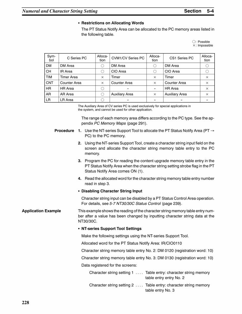
5-4SectionNumeral and Character String Setting
228
S Restrictions on Allocating Words
The PT Status Notify Area can be allocated to the PC memory areas listed inthe following table.
f: Possible×: Impossible
Sym-bol C Series PC Alloca-
tion CVM1/CV Series PC Alloca-tion CS1 Series PC Alloca-
tion
DM DM Area f DM Area f DM Area f
CH IR Area f CIO Area f CIO Area f
TIM Timer Area × Timer × Timer ×CNT Counter Area × Counter Area × Counter Area ×HR HR Area f -- -- HR Area ×AR AR Area f Auxiliary Area × Auxiliary Area ×LR LR Area f -- -- -- --
The Auxiliary Area of CV series PC is used exclusively for special applications inthe system, and cannot be used for other application.
The range of each memory area differs according to the PC type. See the ap-pendix PC Memory Maps (page 291).
Procedure 1. Use the NT-series Support Tool to allocate the PT Status Notify Area (PT→PC) to the PC memory.
2. Using the NT-series Support Tool, create a character string input field on thescreen and allocate the character string memory table entry to the PCmemory.
3. Program the PC for reading the content upgrade memory table entry in thePT Status Notify Area when the character string setting strobe flag in the PTStatus Notify Area comes ON (1).
4. Read the allocated word for the character stringmemory table entry numberread in step 3.
S Disabling Character String Input
Character string input can be disabled by a PT Status Control Area operation.For details, see 5-7 NT30/30C Status Control (page 239).
Application Example This example shows the reading of the character stringmemory table entry num-ber after a value has been changed by inputting character string data at theNT30/30C.
S NT-series Support Tool Settings
Make the following settings using the NT-series Support Tool.
Allocated word for the PT Status Notify Area: IR/CIO0110
Character string memory table entry No. 2: DM 0120 (registration word: 10)
Character string memory table entry No. 3: DM 0130 (registration word: 10)
Data registered for the screens:
Character string setting 1 Table entry: character string memory. . . .table entry entry No. 2
Character string setting 2 Table entry: character string memory. . . .table entry No. 3

Exported From
Exported To
U. S. A.
Australia
U. S. A. Australia Japan
Taiwan New Zealand China
Character-string memory table #2
Character-string memory table #3
Touch switches
5-5SectionAlarm Lists
229
S PC Program
Include the following in the PC ladder program.
@MOV(21)111
DM0106
11210(1)
Notification word for content upgradememory table entryWord that stores the character stringmemory table entry number
Character stringsetting strobe flag
S Program Operation
(1) When the character string setting strobe flag (IR/CIO 11210) comesON (1),the contents of IR/CIO0111 (the word where the content upgrade memorytable entry is located) are transferred to DM 0106. The number of the char-acter string memory table entry that contains the upgraded data is stored inDM 0106 (in this case it is 0002 or 0003).
If the character string memory table entry is allocated to a PCword, the val-ue input to it can be read easily by accessing the allocated word.
In this case, the contents of character string memory table entry #2 arestored in DM 0120 to 0129 and the contents of character string memorytable entry #3 are stored in DM 0130 to 0139.
5-5 Alarm Lists
5-5-1 Allocated Bits of Bit Memory TableThe alarm list function automatically displays and clears alarm messages (con-tents of character string memory table entries) that correspond to the allocatedbits of memory table entries, in accordance with the status of these bits.
Bitmemory table entries aremanagedby allocation to designatedPCbits. Spec-ify the area and bit number.

5-5SectionAlarm Lists
230
S Available Allocation Bits
The bit memory table entries can be allocatedwords in the following PCareas.
f: Possible×: Impossible
Sym-bol C Series PC Alloca-
tion CVM1/CV Series PC Alloca-tion CS1 Series PC Alloca-
tion
DM DM Area f DM Area f DM Area f
CH IR Area f CIO Area f CIO Area f
TIM Timer Area × Timer × Timer ×CNT Counter Area × Counter Area × Counter Area ×HR HR Area f -- -- HR Area ×AR AR Area f Auxiliary Area × Auxiliary Area ×LR LR Area f -- -- -- --
The Auxiliary Area of CV series PC is used exclusively for special applications inthe system, and cannot be used for other application.
The range of respective area varies with the type of PC. Refer to the appendixPC Memory Maps (page 291).
Whendatamemory (DM) is specified, specify thebit number (00 to15) after theword number.
5-5-2 Displaying Alarm Lists Using Bit Memory Table EntriesThis section explains the actual procedure used to display the alarm messagesof the alarm list function on the screen of the NT30/30C.
In order to display an alarm message, the allocated bit of the bit memory tableentry allocated to the PC has to be switched ON.
No. 9
No. 10
No. 11Character string tableentry No. 54Library data FD34
Character string tableentry No. 32
Image dataFE68
Character string tableentry No. 50Image data FE52Character string tableentry No. 32Image data FE68
NT30/30C PC
Warning message and image/library datacorresponding to bit memory table entryNo.10.
Allocated bit (bit memory tableentry 10)
1 1 (ON)
The relationship between the status of the allocated bit of the bit memory tableentry and the corresponding alarm message is as follows:
0 (OFF): Deleted1 (ON): Displayed
Procedure 1. Select Memory Table (TBL EDIT with the DOS version) from the NT-seriesSupport Tool editingmenu, set the allocated bit of the bit memory table entryin the PC area, then set the corresponding alarm message.
2. When creating screen data with the NT-series Support Tool, register thealarm list specified by the bit memory table entry in (1) above for the screen.
3. Program the PC to switch the allocated bit of the bit memory table entry ONand OFF.

Alarm listStarting bit table entry number: 20Number of accessed table entries: 5
Image/library data display area
5-5SectionAlarm Lists
231
S Image/library Data Corresponding to Alarm Messages
Apart from alarmmessages, image/library data can also be set for bit memorytable entries. The alarm list is composed of touch switches and touching(pressing) an alarmmessagewill display the corresponding image/library datafor your guidance.
Example of Alarm List Display
In this example, if the temperature in awater tank rises above theupper limit, a bitis turned ON, and the alarm message corresponding to it is displayed.
S NT-series Support Tool Settings
The following settings are made using the NT-series Support Tool.
Bit memory table entry No. 20: IR/CIO 001512Bit memory table entry No. 21: IR/CIO 000407Bit memory table entry No. 22: AR 000000Bit memory table entry No. 23: LR 001003Bit memory table entry No. 24: LR 001004Data registered for the screen: Alarm list
Y
B
S PC Program
Ladder programming to control the NT30/30C is not required.

Contents of character string memory table entrycorresponding to bit memory table entry No. 22
Contents of character string memory table entrycorresponding to bit memory table entry No. 21
5-5SectionAlarm Lists
232
S NT30/30C Operation
When the created alarm message screen is displayed, the following opera-tions will take place in accordance with the status of the allocated bits.
- When all allocated bits are OFF
Y
B
↓
- When AR0000 comes ON
WATER TANK OVERHEATING Y
B
↓
- If IR/CIO 00407 then comes ON
If an alarm list with multi-PROCESS 3 STOPPED Y
If an alarm list with multi-ple lines is created,alarms are displayed in
WATER TANK OVERHEATINGalarms are displayed indescending order of bitmemory table entry num-memory table entry num-bers.If the bit memory tableIf the bit memory tableentries are set in ascend-ing order of priority the
Bing order of priority, thedisplay will also be ar-ranged in accordanceranged in accordancewith the order of prioritywith the order of priority.
↓

5-5SectionAlarm Lists
233
- When the second from top alarm message is pressed
The alarm list is composedof touch switches. By
PROCESS 3 STOPPED Y
of touch switches. Bypressing the touch switch ofa displayed alarm message,corresponding image/library
WATER TANK OVERHEATING
p y gcorresponding image/librarydata can be displayed. Theselected alarm message isselected alarm message ishighlighted.
It is also possible to setcorrespondences betweenbit memory table entries
Bbit memory table entriesand screen numbers. Here,if the second alarmif the second alarmmessage is pressed again,h dimessage is pressed again,the corresponding screenwill be displayed.
↓
- When IR/CIO 00407 returns to the OFF status
WATER TANK OVERHEATING Y
B
Image/library data corresponding to se-cond from top alarm message
URGENT
Check the thermostat!

Reference
5-6SectionClock Function
234
5-6 Clock FunctionThe NT30/30C has a clock function for setting the date and time.This section explains how to set the date and time, and how to notify the date andtime to the PC.
5-6-1 About the Clock FunctionThe clock function uses the numeral memory table entries numbered 247through 255: these memory table entries are used exclusively for clock data.
As shown in the table below, numbers 247 through 253 are for display and read-ing only, and numbers 254 and 255 are for time setting. Numbers 247 through253 store clock data that is updated by the internal clock of the NT30/30C. Thisdata cannot be rewritten by the PC.
When the NT battery voltage drops, the clock function cannot operate correctlywhen the power is switched OFF.
FunctionNumeral
memory tableentry number
Bit Information Value Remarks
Display/readingonly
247 Second 00 to 59only 248 Minute 00 to 59
249 Hour 00 to 23 24-hour system
250 Date 01 to 31
251 Month 01 to 12
252 Year 00 to 99 Last 2 digits of year
253 Day of week 00 to 06 See below
Setting only
254
0 to 78 to 1516 to 2324 to 31
SecondMinuteHourDate
00 to 5900 to 5900 to 2301 to 31
24-hour system
255
0 to 78 to 1516 to 2324 to 31
MonthYear
Day of weekVacant
01 to 1200 to 9900 to 06Always 00
Last 2 digits of yearSee below
* The numerical values that correspond to the days of the week are as follows:
Day ofweek Sun Mon Tue Wed Thu Fri Sat
Value 00 01 02 03 04 05 06
Setting example: April 27 (Thu), 1995, 14:53:30
254
255
27 14 53 30
00 04 95 04
5-6-2 Date and Time DisplayIn order to display the date or time, an area in which the contents of numeralmemory table entries 247 through 253 can be displayed must be set duringscreen creation with the NT-series Support Tool.
Numeral memory table entries 247 through 253 store clock data that is updatedby the internal clock of the NT30/30C. This data cannot be rewritten by the PC.

Reference
5-6SectionClock Function
235
5-6-3 Date and Time SettingWhen thedate and timeare set from thePC, the contents of the numeralmemorytable entries numbered 254 and 255 are rewritten. It is possible to use themeth-od of copying between memory table entries to set the time, as shown below.
S t is also possible to set the date and time by using function key [F3] (Time) onthe Tool Settings screen of the NT-series Support Tool.For details, see the NT-series Support Tool for Windows Operation Manual(V061).
S It is also possible to set the date and time by rewriting the contents of numeralmemory table entries 254 and 255 using the numeral setting function.
Numeralmemory table entries 254 and255 are exclusively for time setting. Theycan be allocated to an area of the PC for other uses. It is possible to rewrite thecontents of these memory table entries by first writing the new setting into tableentries other than 254 and 255 and then copying it into table entries 254 and 255by using the memory table entry copy function.
Date, hour,minute, second
Copy
NT30/30C PC
DM0000
DM0002Day of wheek,year, month
Date, hour,minute, second
--
--Day of wheek,year, month
0
1
254
255
DM0000
DM0001
DM0002
DM0003
Minute, second
Date, hour
Year, month
Day of week
95 / 03 / 219 / 50 / 18
S Available allocation words
The memory table can be allocated words in the following PC areas. For timesetting, two words have to be allocated for each table entry.
f: Possible×: Impossible
Sym-bol C Series PC Alloca-
tion CVM1/CV Series PC Alloca-tion CS1 Series PC Alloca-
tion
DM DM Area f DM Area f DM Area f
CH IR Area f CIO Area f CIO Area f
TIM Timer Area × Timer × Timer ×CNT Counter Area × Counter Area × Counter Area ×HR HR Area f -- -- HR Area ×AR AR Area f Auxiliary Area × Auxiliary Area ×LR LR Area f -- -- -- --
The Auxiliary Area of CV series PC is used exclusively for special applications inthe system, and cannot be used for other application.
The range of respective area varies with the type of PC. Refer to the appendixPC Memory Maps (page 291).
Procedure 1. Allocate the two memory table entries that are to be the copy source for thesetting to areas in the PC. Two wordsmust be allocated for each table entry.

5-6SectionClock Function
236
2. Next, at the PC, specify the date and time that are to be set in numeralmemory table entries 254 and 255 in these allocated words.
3. Copy the settings from the copy source numeral memory table entries to nu-meral memory table entries 254 and 255.
For the method for copying memory table entries, seeCopying Memory TableEntries (page 212).
S Important Points Concerning the Numeral Memory Table Entries Usedfor the Clock Function
Donot allocate the numeralmemory table entries towhich the clock function isassigned (numbers 247 to 255) to PC words.
Numeral memory table entries 247 through 253 are exclusively for display(readonly).Donot attempt towrite data to thembyusingnumeral settings or bycopying between memory table entries.
Numeral memory table entries 254 and 255 are exclusively for time setting(write only). Do not use them for numeral settings or graph displays.
Initial values set with the NT-series Support Tool are invalid in the case of nu-meral memory table entries 247 through 255.
Date and Time Setting Example
The following is an example of setting the date and time from the PC.In this example, a C200H (type C200H-CPU11,21,22,23,31) - which has a timefunction - is used. The time function is assigned to words AR 18 to 21 of theC200H.
S NT-series Support Tool Settings
The following settings are made using the NT-series Support Tool.
PT Status Control Area: IR/CIO 0100
Numeral memory table entry No. 264: DM0000 (words: 2)
Numeral memory table entry No. 265: DM0002 (words: 2)
Data registered on the screen: Numeral memory table entry Nos.247 to 252
Numeral memory table entry No. 251 (2-digit display)
Numeral memory table entry No. 252(2-digit display)
Numeral memory table entry No. 250(2-digit display)
Numeral memory tableentry No. 249(2-digit display)
Numeral memory table entry No. 247(2-digit display)
19 95 4 20
9 50 18
Numeral memory table entryNo. 248 (2-digit display)
/ /
/ /

5-6SectionClock Function
237
S PC Program
Include the following in the ladder program.
@XFER(70)#0004
00000
@MOV(21)#1254
@MOV(21)#1255
TIM001
@MOV(21)#0625101
102
102
AR18DM0000
@MOV(21)#0264101
TIM001
#0010(1.0S)
S Program Operation
When the created screen is displayed on the NT30/30C and the program isexecuted, the operation is as follows.
(1) When IR/CIO 00000 comes ON, the date and time (AR 18 to 21) set in thePCare read, andwritten to thewords (DM0000 to 0003) allocated to numer-al memory table entries 264 and 265.
(2) Copy the contents of numeral memory table entry 264 (day, hour, minute,second) into numeral memory table entry 254, which is used for setting theclock function.
(3) After waiting about a second for the memory table entry copy operation instep (2) to be completed, copy the contents of numeral memory table entry265 (day of the week, year, month) into numeral memory table entry 255,which used for setting the clock function.
The date and time set at the PC will also be set at the NT30/30C and displayed.

5-6SectionClock Function
238
5-6-4 Notification of the Date and Time to the PC
The date and time set at the NT30/30C can be notified to the PC. The numeralmemory table entries numbered 247 through 253 are used for display. They can-not be allocated to PC areas.
The method used to notify the date and time is copying between memory tableentries.
Numeral memory table
Copy
NT30/30C PC
DM0000
DM0001
0
1
247
248
DM0000
DM0001
DM0002
Second
Minute
HourDM00022
249
Second
Minute
Hour
Second
Minute
Hour
DM
Procedure 1. Allocate an area in the PC to the numeralmemory table entries (number cor-responding to the data to be read) that are to be made the copy destination.
2. Copy the contents of numeralmemory table entries 247 to 253 to the numer-al memory table entries allocated as the copy destination in step (1).The copied date and time is notified to the area in the PC.
S Important Points Concerning Numeral Memory Table Entries Used forthe Clock Function
Numeral memory table entries 247 through 253 store clock data, which is up-dated by the internal clock of the NT30/30C. This data cannot be rewritten bythe PC.
Numeral memory table entries 247 through 253 are exclusively for display(readonly).Donot attempt towrite data to thembyusingnumeral settings or bycopying between memory table entries.
Do not allocate the numeralmemory table entries towhich the clock function isassigned (numbers 247 to 255) to PC words.
Example of Reading the Time Set for the NT30/30C
This is the procedure for reading the time (hour, minute) set for the NT30/30C.
S NT-series Support Tool Settings
The following settings are made using the NT-series Support Tool.
PT Status Control Area: IR/CIO 0100
Numeral memory table entry No. 258: DM0000 (one word)
Numeral memory table entry No. 259: DM0001 (one word)

5-7SectionNT30/30C Status Control
239
S PC Program
Include the following in the ladder program.
@MOV(21)#1258
00000
@MOV(21)#0248
@MOV(21)#1259
TIM000
@MOV(21)#0249101
102
101
102
TIM001
#0010(1.0S)
S Program Operation
When the program is executed, the operation is as follows.
(1) When IR/CIO 00000 comesON, the contents (minutes) of numeralmemorytable entry 248, which is used for reading the clock function, are copied tonumeral memory table entry 258.
(2) After waiting one second for the memory table entry copy operation in step(1) to be completed, copy the contents of numeral memory table entry 249(hours), which used for reading the clock function, into numeral memorytable entry 259.
The hour andminute set in the NT30/30C are stored in DM0000 and DM0001,which are the words allocated to numeral memory table entries 258 and 259.
5-7 NT30/30C Status ControlIn order to control the status of the NT30/30C from the PC, the PT status controlbits in the PT Status Control Area are used.
The statuses of the NT30/30C can be controlled from the PC by writing controldata to thePTstatus control bits of thePTStatusControlAreaallocated in thePCmemory.
Buzzer sounds
ScreenOFF
PT Status Control Area
Screen switch setting
Control data
NT30/30C PC
PT status control bits
Copy memorytable entry setting

Reference
Reference
5-7SectionNT30/30C Status Control
240
5-7-1 Controllable NT30/30C FunctionsPT Status Control Bits in the PT Status Control Area
Controlled Item 1 (ON) 0 (OFF)
Screen display Performed Not performed
Continuous buzzer Sounded Not sounded
Intermittent buzzer (short) Sounded Not sounded
Display historyinitialization Performed Not performed
Backlight color Red White
Intermittent buzzer (long) Sounded Not sounded
Backlight mode Lit Flashing
Screen printing Performed Not performed
Window opening Disabled Enabled
Numeral/character stringinput Disabled Enabled
Bit 10 (backlight color) is effective when using an NT30.
The PC status control bits remain unchanged if the NT30/30C status is changedwith the screen attributes or memory switches, whichmeans that the statuses ofthe PT status control bits do not match the actual status of the NT30/30C. Forexample, the buzzer may sound even though the setting for continuous buzzerbit 13 is OFF.
In this kind of case, control the NT30/30C by using the PT status control bits.
S Screen Display (Bit 15)
Thescreendisplay bit is used to display and clear the screen to prevent burn-inon the CRT. Set bit 15 to 0 (OFF) to clear the screen. The backlight will also goOFF at the same time.
When the screen has been cleared, the last displayed screen can be redis-played either by turning bit 15ON, or by pressing a touch switch. The backlightwill also light at the same time.
S Insteadof turningbit 15ON,ascreencanbedisplayedbyspecifying its screennumber. For details on screen switching, see Switching the Screen Display(page 197).
S If the screen is cleared and bit 15 is ON, turn bit 15 OFF and then back ONagain.
S Continuous Buzzer (Bit 13), Short Intermittent Buzzer (Bit 12) and LongIntermittent Buzzer (Bit 9)
The continuous buzzer sounds continuously without interruption.The short intermittent buzzer sounds for 0.5 seconds at 0.5 second intervals.The long intermittent buzzer sounds for 1.0 seconds at 1.0 second intervals.
If 1 (ON) is specified for more than one of the three buzzers at the same time,the buzzers will sound in accordance with the following order of priority:
0 0 0 0 0
151413121110 9 8 7 6 5 4 3 2 1 0 Bit
0
Wordn+3
PT status control bits PT status control designation
15 14 13 12 11 10 9 8 7 6 5 Bit
Set bits 4 to 0 to 0 (OFF).

5-7SectionNT30/30C Status Control
241
1. Continuous buzzer2. Short intermittent buzzer3. Long intermittent buzzer
Another way to stop a buzzer sounding is to use a touch switch to which thebuzzer stop attribute function is allocated.
Whether or not the buzzer actually sounds also depends on the setting of thebuzzer memory switch of the NT30/30C. For details on this setting, seeUsingthe buzzer (page 93).
In addition to PT status bit operations, the buzzer status can also be controlledby using screen attributes. The screen attributes are set with the NT-seriesSupport Tool.
Buzzer attribute: Set whether the screen will sound or not when a screen isdisplayed, and, if it sounds, the type of buzzer.
S Display History Initialization (Bit 11)
Display history initialization initializes the display history in the NT30/30C.
When bit 11 is switched from 0 (OFF) to 1 (ON), the display history in theNT30/30C is initialized.
After initialization, it returns to the 0 (OFF) status.
S Backlight Color (Bit 10), Backlight Mode (Bit 8)
In the case of the NT30, the backlight is controlled by the combination of bit 10and bit 8 statuses, as shown below.
BitBacklight status when the bit 15 status is 1 (ON)
10 8Backlight status when the bit 15 status is 1 (ON)
0 0 Flashing in white (lit in white⇔ OFF)
0 1 Lit in white
1 0 Flashing in red (lit in red⇔ OFF)
1 1 Lit in red
In the case of the NT30C, the display flashes in white when the bit 8 status is 0(OFF) and is lit in white when the bit 8 status is 1 (ON) (bit 10 is ineffective).
When the backlight is set to be OFF (i.e., when the status of bit 15 is 0 (OFF)),the backlight color (white or red) and backlight mode (flashing or continuouslylit) settings are ineffective.
S Screen Printing (Bit 7)
Hard copies of the screen can be made by connecting a printer to theNT30/30C.
When bit 7 is set from0 (OFF) to 1 (ON), printing of the screen displayed at thattime starts. Note that it is not possible to stop printing part way through.Start printing after confirming that bit 7 (printer operating status) of the PT sta-tus notification area is in the 0 (OFF) status.
When printing starts and bit 7 of the PT status notification area has been set tothe 1 (ON) status, the screen printing bit is returned to 0 (OFF).
S Window Opening (Bit 6)
It is possible to display a partial screen overlying the currently displayedscreen. This partial screen is called a window, and control of windows can be

5-7SectionNT30/30C Status Control
242
allocated to touch switches. Window opening is specified to disable the open-ing of windows using touch switches.
When bit 6 is set to 1 (ON), windows will not open even if a window openingtouch switch is pressed, and currently open windows are closed.
S Numeral/Character String Input (Bit 5)
Input of numerical values and character strings into numeral/character stringinput fields and thumb wheel type input can be disabled using this bit.
When bit 5 is set to 1 (ON), it will not be possible to input anything into inputfields by pressing touch switches (or input to the input terminals of the B7AUnit) to which numeric keys and character string keys are allocated.
It will also not be possible to change numerals using thumb wheel type input.
5-7-2 How to Control NT30/30C FunctionsThis section describes how to control the functions of the NT30/30C.
S Restrictions on Allocating Words
The PT Status Control Area (PC → PT) can be allocated to the PC memoryareas listed in the following table.
f: Possible×: Impossible
Sym-bol C Series PC Alloca-
tion CVM1/CV Series PC Alloca-tion CS1 Series PC Alloca-
tion
DM DM Area f DM Area f DM Area f
CH IR Area f CIO Area f CIO Area f
TIM Timer Area × Timer × Timer ×CNT Counter Area × Counter Area × Counter Area ×HR HR Area f -- -- HR Area ×AR AR Area f Auxiliary Area × Auxiliary Area ×LR LR Area f -- -- -- --
The Auxiliary Area of CV series PC is used exclusively for special applications inthe system, and cannot be used for other application.
The range of eachmemory area differs according to thePC type.See the appen-dix PC Memory Maps (page 291).
Procedure 1. Use theNT-seriesSupport Tool to allocate thePTStatusControl Area (PC→PT) to the PC memory.
2. Program the PC to write control data to the PT status control bits of the PTStatus Control Area.
S Control Timing of PT Status Control Bits
The PT status control bit is not read when the NT30/30C starts up. It is onlyread, and control is only executed, when the contents of the PT Status ControlArea are changed after the NT30/30C has been started up.
Since control of the NT30/30C statuses is executed after the bits correspond-ing to thePTstatus control bits have changed, to execute control again the cor-responding bits must be specified again.
Application Example This example is of the NT30/30C being used as a warning lamp by using PT sta-tus control bits.

5-7SectionNT30/30C Status Control
243
S NT-series Support Tool Settings
Make the following setting using the NT-series Support Tool.
Allocated Word for the PT Status Control Area: IR/CIO 0100
S PC Program
Include the following in the PC ladder program.
@MOV(21)#A000103
09002
09003
09002
@MOV(21)#9000103
@ANDW(34)103
#CFFF
(1)Display the screen, sound continuous buzzerWord for PT status control
(2)Display the screen, sound short intermittentbuzzerWord for PT status control
(3)Word for PT status controlOnly continuous and short intermittentbuzzers are 0Word for PT status control
09003
09003
103
S Program Operation
(1) ThePT status control bits are set as shown belowwhen IR/CIO 09002 turnsOFF. This command block is not executed when IR/CIO 09003 is ON.
Screen display (bit 15) 1 (Performed)
Continuous buzzer (bit 13) 1 (Sounded)
The NT30/30C continuous buzzer sounds.
(2) ThePT status control bits are set as shown belowwhen IR/CIO 09003 turnsOFF.
Screen display (bit 15) 1 (Performed)
Short intermittent buzzer (bit 12) 1 (Sounded)
The NT30/30C short intermittent buzzer sounds.
(3) The PT status control bits are set as shown below when both IR/CIO 09002and IR/CIO 09003 turn ON.
Continuous buzzer (bit 13) 0 (Not sounded)
Short intermittent buzzer (bit 12) 0 (Not sounded)
The NT30/30C buzzer stops.

5-8SectionNotifying the PC of PT Operating Status
244
5-8 Notifying the PC of PT Operating StatusIn order to access the NT30/30C status from the PC, PT status in the PT statusnotification area is used.
The status (operating statuses, etc.) of the NT30/30C can be determined fromthePCby reading thePTstatusword in thePTStatusNotify Areaallocated in thePC memory.
NT30/30C PC
PTstopped
PT Status Notify Area
Currently displayed screen
Screennumber
Content upgrade memory table entry
PT status
5-8-1 Accessing NT30/30C Status
PT Status Notification Bits in the PT Status Notify Area
Controlled Item 1 (ON) 0 (OFF)
PT operating status Operating Stopped
Battery Low Normal
Screen switch strobe flag
Numeral setting strobe flag
Character string setting strobe flag
Printer operating sta-tus Printing Stopped
S PT Operating Status (Bit 15)
When theNT30/30C is in theRUNmode this bit is set toON (1). In othermodesandwhile the systemmenu is displayed it is OFF (0).When this bit is OFF allo-cated bits and words cannot be read or written to.
S Battery (Bit 13)
If the voltage of the backup battery for the NT30/30C memory becomes low,this bit is set to ON (1).
S Screen Switch Strobe Flag (Bit 12)
When thescreendisplayedon theNT30/30C is switchedbyadesignation fromthe PC, by the stand-alone function or by the operation of the allocated bit of abit memory table entry, the screen switch strobe flag comes ON (1). On notifi-cation to the PC, it returns to the OFF (0) status.
For details onhow thescreen switch strobe flag is used, seeNotifying thePCofthe Display Screen (page 199).
151413121110 9 8 7 6 5 4 3 2 1 0 Bit
0 0 0
Wordm+2
PT statusnotification bits 0 0 0 0 0 0 0 PT status
15 14 13 12 11 10 9 8 7 Bit

5-8SectionNotifying the PC of PT Operating Status
245
S Numeral Setting Strobe Flag (Bit 11)
When numerical data is input to a numeral table entry using the NT30/30C nu-meral setting function, the numeral setting strobe flag comesON (1). On notifi-cation to the PC, it returns to the OFF (0) status.
For details on how the numeral setting strobe flag is used, seeNotifying thePCof Numbers (page 224).
S Character String Setting Strobe Flag (Bit 10)
This bit is set to 1 when a character string is input to a character stringmemorytable entry by using the character string setting function. On notification to thePC, the bit is set to 0 (OFF).
For details, see Notify the PC of Character Strings (page 227).
S Printer Operating Status (Bit 7)
This bit is set to 1 (ON)when screen printing is executed at a printer connectedto theNT30/30C in accordancewith an instruction from a touch switch (screenprint key) or from the PC. On completion of printing the bit is set back to 0(OFF). Note that if theNT30/30C systemmenu or an error screen is displayed,the bit will be set to 0 (OFF) even if the printer is printing.
For details, see NT30/30C Status Control (page 239).
5-8-2 Reading NT30/30C Operating StatusThis section explains how to determine the status of the NT30/30C, and accessits operating status.
S Restrictions on Allocating Words
The PT Status Notify Area (PT → PC) can be allocated to the PC memoryareas listed in the following table.
f: Possible×: Impossible
Sym-bol C Series PC Alloca-
tion CVM1/CV Series PC Alloca-tion CS1 Series PC Alloca-
tion
DM DM Area f DM Area f DM Area f
CH IR Area f CIO Area f CIO Area f
TIM Timer Area × Timer × Timer ×CNT Counter Area × Counter Area × Counter Area ×HR HR Area f -- -- HR Area ×AR AR Area f Auxiliary Area × Auxiliary Area ×LR LR Area f -- -- -- --
The Auxiliary Area of CV series PC is used exclusively for special applications inthe system, and cannot be used for other application.
The range of each memory area differs according to the PC type. See the ap-pendix PC Memory Maps (page 291).
Procedure 1. Use the NT-series Support Tool to allocate the PT Status Notify Area (PT→PC) to the PC memory.
2. Program the PC to read the PT status word of the PT Status Notify Area andcheck each bit status.

5-8SectionNotifying the PC of PT Operating Status
246
S Report Timing of PT Status Notify Bit
The information in the PC status notify area (PT → PC) is written to the PCwhen the NT30/30C status is changed during operation.
Example of Using the PT Status Notify Bit
An operation example in which theNT30/30C status is checked by operating thePT status notify bit is explained below.
S NT-series Support Tool Settings
Perform the following setting with the NT-series Support Tool.
PT Status Notify Area allocated word: IR/CIO 0110
S PC Program
Include the following in the PC ladder program.
@MOV(21)#0001DM0001
11215
11213
11215
@MOV(21)#0002DM0001
@MOV(21)#0003DM0001
(1)NT30/30C: stopped, Battery: lowPT status error storage word
(2)NT30/30C: stopped, Battery: normalPT status error storage word
(3)NT30/30C: operating, Battery: lowPT status error storage word
11213
11213
11213@MOV(21)#0004DM0001
(4)NT30/30C: operating, Battery: normalPT status error storage word
S Program Operation
(1) If PT operating status (IR/CIO 11215) is turned OFF (0) and battery (IR/CIO 11213) is turned ON (1), 1 (NT30/30C stop, low battery voltage) istransmitted to DM0001.
(2) If PT operating status (IR/CIO11215) is turned OFF (0) and battery (IR/CIO 11213) is turned OFF (0), 2 (NT30/30C stop, normal battery voltage)is transmitted to DM0001.
(3) If PT operating status (IR/CIO11215) is turnedON (1) and battery (IR/CIO11213) is turned ON (1), 3 (NT30/30C running, low battery voltage) istransmitted to DM0001.
(4) If PT operating status (IR/CIO11215) is turnedON (1) and battery (IR/CIO11213) is turnedOFF (0), 4 (NT30/30C running, normal battery voltage) istransmitted to DM0001.

247
SECTION 6Troubleshooting and Maintenance
This section describes the action to take when NT30/30C errors occur, and how to carry out maintenance and inspections toprevent the occurrence of errors.
6-1 Hardware Faults 248. . . . . . . . . . . . . . . . . . . . . . . . . . . . . . . . . . . . . . . . . . . . . . . . . . . . . . . . .6-2 Responding to Displayed Error Messages 249. . . . . . . . . . . . . . . . . . . . . . . . . . . . . . . . . . . . .
6-2-1 Errors Occurring when the Power is Turned ON 249. . . . . . . . . . . . . . . . . . . . . . . . .6-2-2 Errors Occurring During Operation 250. . . . . . . . . . . . . . . . . . . . . . . . . . . . . . . . . . .6-2-3 Errors Occurring on Screen Data Initialization and Transfer 250. . . . . . . . . . . . . . . .6-2-4 Communication Errors 250. . . . . . . . . . . . . . . . . . . . . . . . . . . . . . . . . . . . . . . . . . . . .
6-3 Maintenance of the NT30/30C 252. . . . . . . . . . . . . . . . . . . . . . . . . . . . . . . . . . . . . . . . . . . . . .6-3-1 Replacing the Battery 253. . . . . . . . . . . . . . . . . . . . . . . . . . . . . . . . . . . . . . . . . . . . . .
6-4 Inspection and Cleaning 255. . . . . . . . . . . . . . . . . . . . . . . . . . . . . . . . . . . . . . . . . . . . . . . . . . .

6-1SectionHardware Faults
248
6-1 Hardware Faults
Whena fault relating to theoperationof theNT30/30Coccurs, find the symptoms
in the table below and respond by following the corresponding remedy indicated
in the table.
NT30/30C Symptoms Cause Remedy
POWER indicator fails tocome ON
Power is not being supplied. Check the connections and make sure that power issupplied correctly.(Refer to 2-2-2 Power Supply Connection, page 20.)
Power supply fuse has blown Contact your OMRON service center.
Nothing is displayed onthe screen.
Screen No. 0 has been read at thePC side.
This is not an error. Change the screen number.(Refer to 4-3 Screen Display, page 131.)
Communication with theNT-series Support Toolnot possible.
The Transmit Mode has not beenestablished.
Display the system menu and select the TransmitMode.(Refer to 3-6 Registering the Screen Data, page89.)
Not connected to the NT-seriesSupport Tool.
Check the installation of the connector cable.(Refer to 2-3 Connecting to the Support Tool, page21.)
PT model setting and directconnection setting at the NT-seriesSupport Tool do not match theNT30/30C.
Using the Tool Settings of the NT-series SupportTool, set the PT model and direct connectionsettings that match the NT30/30C.
Cannot communicate withthe PC.
Memory switch settings do notmatch.
Check the communication setting in the MemorySwitch menu of the Maintenance Mode, and matchthe PC and NT30/30C settings.(Refer to 3-5 Setting the Conditions ofCommunications with the PC Using the MemorySwitches, page 83.)
NT30/30C and PC are not correctlyconnected.
Check that the type, length and installation of theconnector cable match the specifications.(Refer to 2-5 Connection to a PC by the Host Linkvia RS-232C, page 23, 2-6 Connection to a PC bythe Host Link via RS-422A, page 40, and 2-7Connection to a PC by the NT Link, page 56.)
In Host Link connection connection,the PC termination resistance settingis incorrect.
Set the PC termination resistance correctly. (Referto 2-6 Connection to a PC by the Host Link viaRS-422A, page 40.
The buzzer sounds andthe RUN indicator turnsOFF.
The NT30/30C is malfunctioningbecause of external noise.
Separate communications cables from the source ofthe noise, and insert noise filters in power lines.
There is no response fromthe touch panel.
The NT30/30C is malfunctioningbecause of external noise.
Separate communications cables from the source ofthe noise, and insert noise filters in power lines.e o c pa e
The touch panel is broken. Test the touch panel using the I/O check menu inMaintenance Mode.
The PC mode changes toMONITOR mode.
During Host Link communications,the NT30/NT30C changes the modeof the PC.
This is an NT30/NT30C specification. Connect viaNT Link when using a PC that supports NT Linkcommunications. (The mode is not changed ifcommunications are performed via NT Link.)
Graph display is notupdated.
A values set for the --100%, 0%, and100% settings for percentage displayis incorrect.
Correct the --100%, 0%, and 100% settings so thatthe following condition is satisfied:--100% setting < 0% setting < 100% setting

6-2SectionResponding to Displayed Error Messages
249
NT30/30C Symptoms RemedyCause
Numeral display andcharacter string display isnot displayed properly.Nothing is displayed for
Because the memory table isallocated to PC memory, display isupdated according to the contents ofPC memory.
When using the contents of a memory table as fixedvalues, do not allocate the memory table to PCmemory.
Nothing is displayed forcharacter string display.There are no messagesdisplayed in the alarm listor alarm history.
The battery voltage dropped andmemory table data was lost.
Replace the battery and execute memory tableinitialization. (Refer to Replacing the Battery onpage 253 and Initializing Memory on page 78.)When not using a battery, turn the resume functionOFF. (Refer to Resume Function on page 96.)
Because the resume function is setto ON, initial values for image datamemory are not reflected in memorytables.
Execute memory table initialization. (Refer toInitializing Memory on page 78.)If the resume function is not required, turn it OFF.(Refer to Resume Function on page 96.)
With indirect specification fornumeral display and character stringdisplay, the number of words in thenumeral memory table is 2.
Set the number of words of the numeral memorytable to 1.
Only * signs are displayedin a numeral display or anumeral input field.
The numeral in the numeral memorytable is over the number of displaydigits.
Check the value for the word in the PC that isallocated to the numeral memory table.When the numeral display or input field has 4 digitsor less, allocate 1 word in the PC to the numeralmemory table.
6-2 Responding to Displayed Error MessagesWhen the NT30/30C displays an error message, find the corresponding symp-toms in the appropriate table below and respond by following the remedy indi-cated in the table.
6-2-1 Errors Occurring when the Power is Turned ONThe table below shows the errors that can occur when the power supply to theNT30/30C is turned ON, and their remedies.
Message Cause Remedy
Memory Unformatted The power was switched OFF duringinitialization of the screen datamemory or while checking thescreen data memory.
Initialize the screen data memory and transmit thescreen data again.
Screen Data Corrupted The power was switched OFF duringscreen data transmission.
Initialize the screen data memory and transmit thescreen data again.
Mark Data Corrupted S The power was switched OFFduring screen data transmission.
S Transmission of screen data wasinterrupted.
Initialize the screen data memory and transmit thescreen data again.
No direct information isset!!Use the NT-series Support Tool toset PT Control Area and PT NotifyArea.
No words have been allocated forthe PT Status Control Area and PTStatus Notify Area.
Allocate words for the PT Status Control Area andPT Status Notify Area by using the NT-seriesSupport Tool.
None (does not start up) Illegal data has been written to thescreen data memory.
Initialize the screen data memory. See 3-4 InitializingMemory (page 78).
None(The buzzer sounds andthe RUN indicator flashesalternately orange andred.)
The system program cannot bestarted up because there is an errorin it.
Contact your OMRON service center.

6-2SectionResponding to Displayed Error Messages
250
Message RemedyCause
Battery Lowered(At the same time, theRUN indicator will light inorange (during operation)or red (when stopped).)
Voltage of battery in the NT30/30C islow.
Change the battery. See Replacing the Battery(page 253).
An illegible message (withmeaningless characters)is displayed
DIP switch SW2 pin 6 on theNT30/30C is OFF. (The Japanesesystem program is installed.)
Switch OFF the power to the NT30/30C, set DIPswitch SW2 pin 6 to ON, and re-install the systemprogram.
Initialize SystemProgram?
DIP switch SW2 pin 7 on theNT30/30C is ON.
After selecting No, switch OFF the power to theNT30/30C, set DIP switch SW2 pin 7 to OFF, andswitch the power back on. DO NOT select Yes.
System ProgramCorrupted
The system program cannot bestarted up because there is an errorin it.
Install the system program with the NT30/NT30CSystem Installer.
System Program is NotDownloaded
The system program cannot bestarted up because it has beendeleted.
The system program has to be re-installed. Contactyour OMRON service center.
6-2-2 Errors Occurring During OperationThe table below shows the errors that can occur during operation of theNT30/30C, and their remedies.
Message Cause Remedy
Setting ErrorArea Type and Word Address
Allocated bits/words set with theNT-series Support Tool not found
After checking the PC area being used, setcorrect bits/words.
Word Address SettingErrorWord Area of Screen data or PTControl Area is wrong. Pleaseconfirm Screen Data.
NT series Support Tool not foundat PC.
correct bits/words.
6-2-3 Errors Occurring on Screen Data Initialization and TransferThe table below shows the errors that can occur when data is written to theNT30/30C screen data memory, and their remedies.
Message Cause Remedy
Initialization Error Hardware fault or screen datamemory life reached
If the same message is displayed even afterexecuting screen data memory initialization orscreen data transmission several times, contactyour OMRON service center.
6-2-4 Communication ErrorsThis section describes the errors relating to communication with the PC that canoccur during operation, and their remedies.
S Operation when a Communication Error Occurs
When a communication error occurs, the error message is displayed at theNT30/30C, and the buzzer sounds. Error messages are displayed when theAutomatic Reset memory switch is set (OFF).
Some error messages are displayed even if the Automatic Reset memoryswitch is set (ON).
S Procedure when a Communication Error Occurs
When an error message is displayed, press the [confirm] touch switch dis-played on the screen. The screen display will return to the RUN mode.

6-2SectionResponding to Displayed Error Messages
251
S Display of Communication Errors
As shown below, communication errors are displayed in the center of thescreen, together with a classification indicating whether they are receive orsend errors.
Screen when an Error Has Occurred during Reception
Error DescriptionSCI. Parity ErrorSCI. Overflow ErrorSCI. Framing ErrorBuffer OverflowTime OutNAK ReceivedUnit # ErrorFCS ErrorChecksum Error
Reception Error
Confirm
Screen when an Error Has Occurred during Sending
Error DescriptionTime Out
Transmit Error
Confirm
Message Cause Remedy
(SCI)Parity ErrorFraming Error
Communication parameters/conditions set incorrectly.
Check whether the parity bit, data bit length, baudrate, stop bit length, and flow control settings of thePC match the settings of the NT30/30C.
Framing ErrorOverrun ErrorBuffer Overflow
Noise caused data corruption duringcommunication.
Use a noise-resistant cable if communication occursin an environment with high levels of noise.
Buffer OverflowThe connectors of the connectingcable are not connected correctly.
Reconnect the cable.
Time Out The connectors of the connectingcable have become disconnected.
Reconnect the cable.
The PC is stopped. Make sure the PC is able to communicate with theNT30/30C.
During transmission of onecommand, a time lapse exceeding 5seconds is detected.
Check the cable connection.
NAK Received(end code simultaneouslydisplayed)
Noise caused data corruption duringcommunication.
Check the allocated bit and word settings.If there is a possibility of noise, separate cablesfrom the source of the noise, and insert noise filtersin power lines. If the NT30/NT30C is used in anenvironment with high levels of noise, use anoise-resistant cable and make the cable length asshort as possible.
Unit # Error The unit # does not match that set inthe PC.
Set the PC unit No. to 0.
The PC is transmitting incorrectdata.
Check PC operation.
Noise caused data corruption duringcommunication.
Use a noise-resistant cable if communication occursin an environment with high levels of noise.
FCS ErrorChecksum Error
The PC is transmitting incorrectdata.
Check PC operation.Checksum Error
Noise caused data corruption duringcommunication.
Use a noise-resistant cable if communication occursin an environment with high levels of noise.

WARNING
WARNING
6-3SectionMaintenance of the NT30/30C
252
6-3 Maintenance of the NT30/30CCarry outmaintenancework in order to ensure that theNT30/30C is alwaysusedin its optimum condition.
Never attempt repairs, modification or disassembly. You could sustain an elec-tric shock.
S Spare PT
It is advisable to have a spare NT30/30C available to minimize system down-time in the event of an NT30/30C failure or if the screen display becomes diffi-cult to read due to deterioration of the display unit.
S Backlight
When the backlight in the display is getting dim and the screen cannot be readeasily, replace the backlight. The backlight can be replaced at the rear of theNT30/30C while it is mounted in an operation panel.
- Replaceable Backlight Model
NT30-CFL01 (for NT30)NT30C-CFL01 (for NT30C)
- Guide to Backlight Replacement
Under normal conditions it can be assumed that the backlight will need to re-placed after about 10,000 hours. However, the life of the backlight does varyin accordance with the environment in which it is used and it should be re-placed when it is getting dim and the screen is getting hard to read.
Replacing the Backlight
Use the following procedure to replace the backlight.
Danger of electric shock. SwitchOFF theNT30/30C power before changing thebacklight.
Procedure 1. Turn OFF the power to the NT30/30C, grasp the backlight unit by its grips(this will cause the catches at either side of the backlight unit to disengagefrom the NT30/30C body) and pull the backlight unit toward you to remove it.
Grips forremoval
2. Fit a new backlight.
After inserting the backlight unit until it is fully home, press firmly on bothsides of part A until you hear a click. Check that the backlight unit catches

Reference
6-3SectionMaintenance of the NT30/30C
253
have engagedwith the NT30/30C, and that the rear face of the backlight unitis parallel with the rear face of the NT30/30C, as shown in the figure below.
Part ACondition of the catches, as seenfrom above
When correctly installed
When correctly installed
6-3-1 Replacing the BatteryThe NT30/30C uses a lithium battery to back up the memory contents.
The battery life is 5 years if theNT30/30C is used in a locationwhere the ambienttemperature is 25_C. If the temperature at the location of use is higher than this,the battery life will be shorter. Change the battery at suitable intervals in accor-dance with the operating environment of the NT30/30C.
It is advisable to keepa spare battery so that the battery canbe replaced immedi-ately if replacement becomes necessary.
S Battery model
C500-BAT08
S Battery Replacement
Replace the battery in the following cases. Thebatterymust be replacedwithin5 days.
- When 5 years have passed since the installation of a new battery.
- When the RUN indicator is lit in orange (during operation) or in red (whenstopped).
- When themessage “Battery Lowered” is displayedonswitchingON thepow-er or resetting the NT30/30C.
- When “Lowered” is displayed when the battery check in the I/O check menuis performed.
S Battery Replacing Method
Replace the battery by following the procedure given below.
Toprotect the contents of thememory, thebatterymust be replaced in less than5 minutes.
Procedure 1. Keep the power ON for at least 1 minute and then turn it OFF.
Unless the power is kept ON for at least 1 minute, the memory contents cannotbe retained for more than 5 minutes without a battery.
2. Open the battery cover on the left side of the rear face of the NT30/30C bygetting a purchase on its upper edge with your fingernails and pulling it to-ward you.Donot try to open the battery coverwith a tool suchas a screwdriv-

Caution
6-3SectionMaintenance of the NT30/30C
254
er insteadof your fingers since thiswill cause scratching or damage the com-ponents inside the cover.
3. Remove the battery that is secured under the battery cover, grip the cable,and pull the connector straight out.
4. Insert the connector of the new battery into the connector on the NT30/30Cand fit the battery under the battery cover.
When inserting the battery connector, make sure that the projection on itfaces to the left, and press it fully home while keeping it straight.
The connector of the new battery must be connected within 5 minutes afterdisconnecting the old battery’s connector. However, the battery can be re-placed while the NT30/30C power is ON, and in this case there is no timerestriction.
5. Close the battery cover, making sure that the cable is not trapped.
When replacing a battery, ensure that the battery terminal does not touch theboard in the NT30/30C.

Correct use
6-4SectionInspection and Cleaning
255
6-4 Inspection and CleaningClean and inspect the NT30/30C regularly to ensure that it is always used in itsoptimum condition.
Cleaning Method If the display is dirty the screen is difficult to see. Clean the screen from time totime as follows.
• In daily cleaning, wipe the display with a soft dry cloth.
• If the soiling cannot be removedwith a dry cloth, wet the cloth with diluted neu-tral detergent (2%), wring it out well and wipe the display with it.
• If rubber or vinyl products, tape, etc. are left stuck to thedisplay for longperiodsthey will cause staining. If such items are stuck to the display, remove themduring cleaning.
Never use volatile solvents such as benzene or thinners, or chemical dusters.These could cause degeneration of the coatings of the NT30/30C display andbody.
Inspection Method In normal environments, inspect the NT30/30C at intervals of between 6monthsanda year. In environments that are extremely hot andhumid, or very dusty envi-ronments, shorten the inspection interval.
S Items Required for Inspection
Prepare the following items before starting the inspection.
• The tools supplied with the NT30/30C
• Screwdrivers (Philips, flat-head)
• Tester (or digital voltmeter)
• Industrial alcohol
• 100% cotton cloth
• Hygrometer (required in some cases)
• Thermometer (required in some cases)
• Synchroscope (required in some cases)
• Pen-writing oscilloscope (required in some cases)
S Points Inspected
Inspect the following points to determine if there is any divergence from thestated criteria. If there is, either improve the surrounding environment so thatthe values fall within the stated range, or adjust the NT30/30C.
Point Inspected Inspection Details Criterion Inspection Instrument
Power supply voltage Fluctuation in power supplyterminal voltage
Permissible voltage fluctuationrange(24 VDC --15% +10%)
Tester
Ambient environmentalconditions
Ambient temperature(temperature in the operationpanel)
0 to 50_C Thermometer
Ambient humidity(humidity in the operationpanel)
35% to 85% Hygrometer
Presence/absence of dust Dust must not be settled Visual inspection

Caution
Reference
6-4SectionInspection and Cleaning
256
Point Inspected Inspection InstrumentCriterionInspection Details
Mounting conditions Looseness of mountingbrackets etc.
To be no looseness Accessory tools
Connector connections ofconnecting cable
To be fully inserted andlocked, with no looseness
Looseness of screws inexternal wiring
To be no looseness Philips screwdriver
Conditions of externalconnecting cables
Faults such as incipientdisconnections.
Visual inspection
Components with limitedlives
Brightness of the backlight Must be sufficiently bright.Backlight life:Brightness is halved afterabout 10,000 hours in use.
Visual inspection
S If a faulty unit is returned for repairs, write as detailed a description of the faultas possible and send this description together with the unit to theOMRONad-dress indicated on the back cover of this book.
S Whendisposing of anPT that is no longer required, be sure to complywith anylocal restrictions that apply to its disposal.
Cautions on replacing the NT30/30CWhen replacing the NT30/30C after discovering a fault during inspections,note the following points:
S Be sure to switch the power OFF before replacement.S After replacement, check that the new NT30/30C is not subject to the sameerror.

257
Appendix ASpecifications
General Specifications
Item Specification
Power supply voltage 24 VDC
Allowable power supply voltage range 20.4 VDC to 26.4 VDC (24 VDC --15% +10%)
Power consumption 15 W max.
Ambient operating temperature 0 to +50_C (with no freezing)
Storage temperature --20 to +70_C (with no freezing)
Ambient operating humidity 35% to 85% (with no condensation)
Operating environment No corrosive gases.
Resistance to electrostatic discharge Level 3 (IEC801-2)In air8 kV, contact6 kV, indirect7 kV
Electromagnetic field strength 10 V/m (IEC801-3)
Fast transient/burst noise Power supply line: 2 kV (IEC801-4)I/O line: 0.25 kV
Damped oscillatory wave Power supply line: 1 kV (IEC255-4)
Vibration resistance 10 to 57 Hz with 0.075 mm single amplitude for a total of 30 min. in X, Y, andZ directions
57 to 150 Hz with 9.8 m/s2 acceleration in X, Y, and Z directions
Shock resistance Malfunction: 15 G, 3 times each in X, Y, and Z directions
Dimensions (mm) 195 x 142 x 56 mm (WxHxD)(when B7A Interface Unit installed: 195 x 142 x 75 mm (WxHxD))
Weight 1.0 kg max.
Enclosure ratings Front panel: Equivalent to IP65 (front face waterproof construction).g
Rear case: IP20
Terminals: IP00
Applicable standards EN61131-2 (1995)EN50081-2 (1992)

Appendix ASpecifications
258
Performance SpecificationsDisplay Specifications
Item Specification
Display panel Display device NT30: Monochrome LCD (2 backlight colors)NT30C: Color STN LCD (with backlight)
Number of dots(resolution)
320 dots horizontally x 240 dots vertically
Effective display area 115.2 mm horizontally x 86.4 mm vertically
View angle Left/right direction: 35_ Up: 25_ Down: 35_
Display color NT30: Backlight white, redNT30C: 8 colors (and intermediate colors can be displayed with tiling
patterns)
Service life 50,000 hours minimum (guidance figure assuming normal use)
Backlight(white cold cathode
Service life 10,000 hours minimum (until brightness reduced to 50%)(white cold cathodetube) Automatic turn-off Can be set to turn off in 10 minutes or 1 hour, or to remain on.
Indicators POWER (Greenindicator)
Lit while power is being supplied.
RUN Lit in green during operation.Lit in orange (during operation) or in red (when NT30/NT30C stopped)if battery voltage becomes low.
Panel Specifications
Item Specification
Touch panel Number of switches: 192 (16 horizontally x 12 vertically)Maximum number that can be registered per screen: 192
Input: Pressure-sensitive type
Threshold force for operation: 1 N min.
Life expectancy: 1 million operations minimum
Expanded I/O (B7A Interface Unit) Input: 8 points/16 pointsOutput: 8 points/16 points(total I/O: 32 points)

Appendix ASpecifications
259
Display Capacity
Item Specification
Displayl (*1)
Character displays Fixed character data (character strings registered for each screen)p yelements (*1) Character string
displays50 positions per screen (40 bytes per string)
Numeral displays 50 positions per screen, 8-digit display
Graph displays 50 positions per screen, capable of displaying signs, % display
Trend graph One frame per screen, 50 items per frame
Broken line graph One frame per screen, 256 items. per frame, 512 points per item, 512 pointsper screen
Graphic displays Can be displayed wherever required
Lamps Max. 1024 lamps per file, 256 positions per screen
Touch switches Max. 1024 per switches file, 192 positions
Numeral settings Display of set numerical values, 50 per screen
Character string set-tings
Display of setting character-strings, 50 per screen
Alarm list 4 groups per screen (The alarm history is displayed in the order of occur-d f b )Alarm history
g p p ( y p yrence and frequency, group by group.)
Clock display Time display of built-in clock by numeral display function
Screen types Normal screen Displays screens registered as normal.yp
Overlapping screens A maximum of 8 registered screens can be displayed overlapping each other.
Consecutive screens A maximum of 8 screens can be displayed sequentially by scrolling.(The screen can be scrolled by keys)
Window screens For input setting numeric keys/character keys (maximum of 50 settings). Win-dow screens use screen numbers 1900 to 1979.
Display historyscreens
Order of occurrence (max. 1023 screens), order of frequency (max. 255times)
Screen attributes Buzzer, display history, numeral setting display, background colors (NT30Conly), backlight color (NT30 only), backlight
Number ofscreens
Max. number ofregistered screens
2000 screenssc ee s
Screen number 0: No display
1 to 2000: User registered screens (However, 1997 screen is a display history occur-rence order screen, 1998 screen is a display history frequency orderscreen, 1999 screen is a host connecting screen, and 1999 screen is thescreen displayed during connection to the host.)
Screen registration method By transferring screen data created using the support tool to the NT30/30C.
Screen saving method (screen datamemory)
Flash memory (storing format unique to NT30/30C)
(*1) The total number of display elements for numeral display, graphs, and numeral settings must be 1024 or less.

Appendix ASpecifications
260
Display Element Specifications
Item Specifications
Display characters Half-size characters (8 x 8 dots): Alphanumerics and symbolsNormal-size characters (8 x 16 dots): Alphanumerics and symbolsMark (16 x 16 dots): User-defined pictographs
(32 x 32 dots)(64 x 64 dots)
Image data: 8 x 8 to 320 x 240 dots, User-defined image character size is setfreely in the unit of 8 x 8 dots.
Library data: 1 x 1 to 320 x 240 dots
Enlargement function Double width, double height, and magnification of 4x, 9x, 16x, 64x
Smoothing processing Available for enlarged characters with magnification of 4x or more
Character display attribute Normal, inverse, flashing, inverse flashing, transparent display
Image data Variable-size pictographSize: Min. 8 x 8 dots, max. 320 x 240 dots
Capable of setting a size in the unit of 8 dotsIncapable of setting the enlarged display, smoothing processing, display attrib-utes such as inverse/flashing.
Library data Combination of any graphicsSize: Min. 1 x 1 dot, max. 320 x 240 dots
Capable of setting any sizeEnlarged display, smoothing processing, and display attributes such as in-verse/flashing are displayed according to the setting registered.
Graphics Continuous straight line, circle, arc, sector, rectangle, polygon
Line type 4 types only for continuous straight line (solid line, broken line, alternate longand short dash, long and two short dashes)
Painting out 10 types
Graphic display attributes Normal/inverse flashing, transparent display
Display color(NT30C only)
8 colors (red, green, blue, yellow, magenta, cyan, white, black)
Color specification(NT30C only)
Display color, background color, boundary color (line color)
Data Quantities
Item Specifications
Character-string data 40 characters (normal-size) x 1000; 744 data are only for reading operation)
Numeral data 8-digit x 1000
Bit data One contact x 256
Mark data 224 (in terms of 16 x 16 dots)
Image data 224
Library data 896
Touch switchesEach 1024
LampsEach 1024

Appendix ASpecifications
261
Special Features
Item Specifications
Buzzer Three kinds of sound (continuous sound, intermittent short-sound, intermittentlong-sound)ON: Reception of a command from the PC, buzzer setting screen
display, error screen display such as abnormal receptionOFF: Reception of a command from the PC, key input, screen
display without buzzer settingSound pressure: Min. 80 dB/Average 87 dB (measured at 10 cm in front)Setting: Set the “Buzzer Sound” to “ON” in the “MEMORY SWITCH
MENU”. “ERR ON” for only when an error occurs.
Maintenance functions S Self-test function, such as memory, switchS Setting condition confirmation function, such as communication conditionS Communication check function
Battery retention S Retention of display history dataS Retention of NT610C memory dataBattery life: Five years (25_C)When the voltage drops: A message “Battery Lowered” is displayed.
The RUN indicator is lit in orange or red.Communication flag (BAT LOW) to the PC isON (1).
Key input sound setting Touch switchInput sound: Sounds for 0.2 second.Setting: Set the “Key Press Sound” to “ON” in the “MEMORY SWITCH
MENU”.
Resume function To retain the contents without initializing the memory table (character string,numeral value) when turning ON the power, resetting, changing over the op-eration mode.Setting: Set the “Resume Function” to “ON” in the “MEMORY SWITCH MENU”.
Screen printing function To print the screen just displayed by means of printer interface connector.Setting: Set an output specification in the “MEMORY SWITCH MENU”.
ESC/P color: Conforms to ESC/P 24-J83C, color printingESC/P grayscale: Conforms to ESC/P 24-J83C, monochrome 8 grayscale
levelsPR201H color: Conforms to PC-PR201H, color printingPR201H grayscale:
Conforms to PC-PR201H, monochrome 8 grayscalelevels

Appendix ASpecifications
262
Communications SpecificationsFor a Host Link via RS-232C
Item Specification
Communications standard EIA RS-232C
Communications settings Start-stop synchronizationBaud rate: 9600, 19,200 bpsData length: 7 bitsStop bits: 2 bitsParity: Even
Connector 9-pin, D-sub connector (female)
Number of Units connected 1 to 1
Transmission distance Max. 15 m
Communications protocol C-series SYSWAY (1:N)
For a Host Link via RS-422A
Item Specification
Communications standard EIA RS-422A
Communications settings Start-stop synchronizationBaud rate: 9600, 19,200 bpsData length: 7 bitsStop bit: 2 bitsParity: Even
Communications terminal block M3.5
Number of Units connected 1 to 1
Transmission distance Max. 500 m
Communications protocol C-series SYSWAY (1:N)
For NT Link
Item Specification
Communications standard EIA RS-232C
Connector 9-pin D-sub connector (female)
Number of Units connected 1 to 1
Transmission distance Max. 15 m

263
Appendix BDimensions
Programming Terminals (NT30-ST131(B)-E, NT30C-ST141(B)-E)
POWER
RUN
195(7.68)
183.5(7.22)
142(5.59)
130.5(5.14)
5 (0.20)55.6(2.19)
Unit : mm(inch)
75(2.95)
Shown with B7A Interface Unit installed.

Appendix BDimensions
264
Mounting bracket dimensions
50(1.97)
154(6.46)
33(1.3)(Min.)37(1.46)(Max.)
15.5(0.61)
Unit : mm (inch)
Mountingplate
Mountingbracket76
(3)
5(0.2)
NT30
POWER
RUN
206(8.11)
60(2.36)
60(2.36)

265
Appendix CUsing RS-232C/RS-422A Link Adapters
This section outlines the external dimensions, procedure for mounting and removal, and specifications of anRS-232C/RS-422A Link Adapter (NT-AL001). Refer to this information when designing the control panel.
Dimensions
om onR NT--AL001
100.274.5
110
4
30
45
53.5
(30)105 max.
Units: mm
30× 114× 100.2 mm (WxHxD): with the RS-422A terminal block cover closed
30× 114× 119.5 mm (WxHxD): with the RS-422A terminal block cover open
Methods for Mounting and RemovalThe RS-232/RS-422 Link Adapter (NT-AL001) can be mounted on a DIN track or in an operation panel.
The RS-422A terminal block of the Link Adapter can be easily removed.
Mounting to a DIN Track
Latch the top part of the rear face of the Link Adapter (“a” in the figure) onto the top edge of theDIN track, and pushthe Unit in the direction indicated by “b” in the figure.
Then fit end plates at the right and left of the Link Adapter to secure it and ensure that it cannot shift laterally.
(b)
(a)

Note
Appendix CUsing RS-232C/RS-422A Link Adapters
266
Removal from a DIN Track
Remove the end plates at right and left of the Link Adapter and, as shown in the figure below, insert a flat bladescrewdriver into the track stopper at the bottom face of the Link Adapter and prize it free.
Mounting to an Operation Panel
Drill twomounting screw holes in an operation panel with a thickness of at least 2mmand secure the Link Adapterwith screws.
30
21
100 110
2-M4Units: mm
In order to ensure a secure and strongmount, mount the Link Adapter in an operation panel with a thick-ness of at least 2 mm (0.08 inch).

267
Appendix DNT30/30C Internal Processing
The following processing is executed inside the NT30/30C. Processing is divided into two types: periodic proces-sing and event processing.
Periodic ProcessingThe following processing is executed inside the NT30/30C to enable high-speed control from the PC.
Usually, the only data read from the PC are the elements used for the currently displayed screen. Even if the con-tents of the PC words allocated to memory tables are changed, these contents are not updated at the PT unlessthememory table is used for the displayed screen. However, the bit memory table that can be usedwith Ver.3 andlater versions of the direct connection function can be set to be read continually.
Reading of of the elements that could not beregistered
NT30/30C (PT) Processing Details of Processing
PT power ON
Initial processing Hardware check, communication status check, etc.,executed
Operation start
Initial values written to the memory tables When the values registered in the NT30/30C are usedas the initial values in the memory tables, these valuesare written into the allocated words of the PC.
Screen switching
Screen element registration
Reading of registered elements
(PT→PC)
(PT→PC)
(PT←PC)
In order to enable fast batch processing, the elementsused in the displayed screen are registered in the PCin advance. Approximately 120 words can beregistered per screen.
The statuses of the registered elements are read fromthe PC and the display is changed.
The status of the elements that were in excess of thenumber that could be registered is read from the PC,and the display is changed. This processing iscontinued until the statuses of all the remainingelements has been read.
If the number of elements that could not be registered islarge, the PT status control area is read after every twoelement readings.
(PT←PC)
Reading of of the elements that could not beregistered
(PT←PC)
Reading of the PT status control area (PT←PC)
Reading of of the elements that could not beregistered (PT←PC)
Reading of of the elements that could not beregistered (PT←PC)
Reading of the PT status control area (PT←PC)
: Processing performed if necessary

Appendix DNT30/30C Internal Processing
268
S Number of Words for Screen Element Registration
The number of words used for screen element registration is as follows.
Allocated words: Number of words
Allocated bits: Number of words calculated by summing the number of bits in each area and taking 1 wordto be 16 bits.
Example:
Character string memory table: 3 of 12 allocated words eachNumeral memory table: 4 of 2 allocated words eachAllocated bits for control: 19 I/O relays, 7 link relays (contiguous bits)
The number of words assigned to character string memory table and numeral memory table is as follows:
12 words¢ 3 + 2 words¢ 4 = 44 words
The assignment for bits is as follows:
19 I/O relays 16 = 1 word with a remainder of 3 bits→ 2 words7 link relays 16 = 0 words with a remainder of 7 bits→ 1 word
The total is therefore 44 words + 2 words + 1 word = 47 words
Elements occupying up to approximately 120 words, calculated in this way, can be registered. If the number ofelements is larger than this, internal processing is increased in proportion to the excess number and this gener-ates a delay in processing.
If the point where the quantity that can be registered is exceeded is in themiddle of an element that spans sever-al words (for example a character string memory table), registration is quit without registering that element.
If there are bit memory table entries that have been set to be read continuously, the requirement for this proces-sing is also registered. If the number of such bit memory table entries is large, processing will be delayed.
S Order of Priority for Registration
Elements are registered in the following order of priority according to their type.
(1) Allocated words of the PT status control area
(2) Allocated bits for control (lamps, lamp bits of touch switches, bit memory table entires)
(3) Allocated words of numeral memory table
(4) Allocated words of character string memory table
If there is more than one element for each of (2) through (4), the elements are registered in accordance with thefollowing priority of word and bit areas:
(1) Data memory (DM)
(2) I/O relays (CH)
(3) Timers (TIM)
(4) Counters (CNT)
(5) Holding relays (HR)
(6) Auxiliary relays (AR)
Within each area, words and bits are allocated from the smallest number up.

Appendix DNT30/30C Internal Processing
269
Event ProcessingWhen the status of the NT30/30C changes during operation, the processing for writing the changed data to therelevant area of the PC memory is executed.
This kind of processing is only executedwhenstatuses change.When changesoccur simultaneously, processingis executed in accordance with the order of priority.
NT30/30C Processing Details of Processing
(PT→PC)
(PT→PC)
Writing to character string memory table
High
Low
Writing to the PT status notify area
Changing the contents of words allocated to the PCwhen the value in a numeral memory table entryhas changed.
Changing the contents of words allocated to the PCwhen the value in a numeral memory table haschanged.
Writing to bits in order to inform the PC that atouch switch and an B7A Unit has been pressed.
Writing to the PT status notify area in order toinform the PC of changes in the PT operatingstatus.
Bit writing
Writing to numeral memory tables
Orderofpriority
(PT→PC)
(PT→PC)
Data is onlywritten toPCbits andnumeral/character stringmemory table entries for elements in screens currentlybeing displayed. If the contents of numeral/character string memory table entries that are not being displayedchange, the changed contents are not written to the PC.

271
Appendix EMaking the Cable to Connect to the PC
Explained below is the method for making the cable that connects the NT30/30C and the PC.
Connect the wires to the connectors in accordance with the connector specification for each unit.
Parts RequiredTwo connectors, two connector covers and one cable are required tomake up a connecting cable.One connectorand one connector cover is supplied with most PCs.
Name Model Delivered with Remarks
Connector XM2A-0901 C series CQM1, C200HS,C200HX/HG/HE, CPM1, SRM1CVM1/CV series CPU UnitCV500-LK201
9-pin, manufactured by OMRON
XM2A-2501 C500-LK203C500-LK201C200H-LK201
25-pin, manufactured by OMRON
DB-25P C500-LK201-V1C120-LK201-V1
25-pin, manufactured by JAE
ConnectorCover
XM2S-0911 C series CQM1, C200HS,C200HX/HG/HE, CPM1, SRM1CVM1/CV series CPU UnitCV500-LK201
9-pin, manufactured by OMRON
XM2S-2511 C500-LK203C500-LK201C200H-LK201
25-pin, manufactured by OMRON
DB-C2-J9 C500-LK201-V1C120-LK201-V1
25-pin, manufactured by JAE
Note Whenconnecting theNT30/30C toanOMRONPLCCjjH , the connector and theconnector hoodmustbe prepared separately since they are not supplied with the CjjH.The connector provided in theCPUUnit of theCjjH is a9-pin connector. For the connection, the follow-ing connector and connector hood should be prepared.
- Connector: XM2A-0901 (9-pin, OMRON)
- Connector hood: XM2S-0911 (9-pin type, OMRON)
Prepare the cable recommended by OMRON.The recommended cables are indicated in the following table.
Name Type Remark
Cable
AWG28¢5PIFVV-SB Multiconductor shielded cable (FUJIKURA, Ltd.)
CableCO-MA-VV-SB5P¢28AWG Multiconductor shielded cable (HITACHI Cable, Ltd.)
Connector Specifications and Wiring for OMRON UnitsThe combination of pin numbers to which the connecting wires are connected differs according to the connectorspecifications for each unit. Check the connector specifications of the unit to be connected and make the wiringconnections for the items in the connection combination indicated below which are applicable.

1 6
95
1 14
2513
Appendix EMaking the Cable to Connect to the PC
272
NT30/30C Connector Specifications (9-pin)
- Electrical characteristics: Complies with EIA RS-232C
- Signal direction: Signal input and output is relative to NT30/30C.
Connector Signal Name AbbreviationSignal DirectionConnector
Pin No. Signal Name AbbreviationInput Output
2 Send data SD (TXD) f
3 Receive data RD (RXD) f
4 Request to send RS (RTS) f
5 Clear to send CS (CTS) f
6 +5V (150 mA Max.) +5V f
9 Signal ground SG (GND) -- --
* Before using the +5V supply of pin No. 6, check that the current capacity of theequipment to be supplied is no greater than 150 mA.The +5V output of NT30/30C is +5V 5% 150 mA max.
Connecting an NT30/30C to a C-Series Host Link
S C-series Host Link Unit 25-pin connector specifications
- Applicable Host Link Unit: C200H-LK201-V1C500-LK201-V1C500-LK203C120-LK201-V1
- Electrical characteristics: Complies with EIA RS-232C
- Signal direction: Signal input and output is relative to the PC.
Connector Signal Name AbbreviationSignal DirectionConnector
Pin No. Signal Name AbbreviationInput Output
1 Frame ground FG -- --
2 Send data SD (TXD) f
3 Receive data RD (RXD) f
4 Request to send RS (RTS) f
5 Clear to send CS (CTS) f
7 Signal ground SG (GND) -- --
14 Optical connector +5V (see note 2) +5V -- --
15 Send signal element timing 2(see note 1) ST2 f
17 Receive signal element timing(see note 1) RT f
20 Data terminal ready ER (DTR) f
24 Data signal element timing (see note1) ST1 f
Note 1. No element timing signals on C200H-LK201-V12. C500-LK201 and C200H-LK201-V1 only

1 6
95
Appendix EMaking the Cable to Connect to the PC
273
S Wiring Connections
TheNT30/30Cdoesnot usepin4 (RS)or pin5 (CS).Either short theRSandCSpinsof thePCconnector togeth-er or set the CTS setting selector switch at the rear face of the Host Link Unit to “0V” (see∗ in the figure).
Connect the cable shield to the connector cover and pin 1 at the Host Link Unit end of the cable only.
23456789
Pinnumber
Abbrevi-ation
SDRDRSCS
SG
RS-232Cinterface
RS-232Cinterface
Pinnumber
Abbrevi-ation
2345678--
FG
SDRDRSCS--SG----
Shield
25-pinconnector
NT30/30C PC (Host Link Unit)
------ER
------20
+5V ∗
Connectorcover
Connectorcover
Connecting an NT30/30C to a C-Series CPU Unit (CjjH)
S C-series CPU Unit (CjjH) 9-pin Connector Specifications
- Applicable CPU Unit: C20H/C28H/C40H/C60H- Electrical characteristics: Complies with EIA RS-232C- Signal direction: Signal input and output is relative to the PC.
Connector Signal Name AbbreviationSignal DirectionConnector
Pin No. Signal Name AbbreviationInput Output
Connector cover Frame ground FG -- --
2 Send data SD (TXD) f
3 Receive data RD (RXD) f
4 Request to send RS (RTS) f
5 Clear to send CS (CTS) f
7 Signal ground SG (GND) -- --
S Wiring Connections
TheNT30/30Cdoesnot usepin4 (RS)or pin5 (CS).Short theRSandCSpinsof thePCconnector together (see∗ in the figure).
Connect the cable shield to the connector cover and pin 1 at both theNT30/30CandCPUUnit ends of the cable.
23456789
Pinnumber
Abbrevi-ation
SDRDRSCS+5V----SG
RS-232Cinterface
Shield
NT30/30C PC CPU Unit
RS-232Cinterface
Pinnumber
Abbrevi-ation
234567----
FG
SDRDRSCS--SG----
9-pin connector
∗
Connectorcover
Connectorcover

1 14
2513
1 6
95
Appendix EMaking the Cable to Connect to the PC
274
Connecting an NT30/30C to a CVM1/CV-Series Host Link Unit
S CVM1/CV-series Host Link Unit connector specifications
- Applicable Host Link Unit: CV500-LK201
- Electrical characteristics: Complies with EIA RS-232C
- Signal direction: Signal input and output is relative to the PC.
Communications Port 1 (25-pin Connector)
Connector Pin Signal Name AbbreviationSignal DirectionConnector Pin
No. Signal Name AbbreviationInput Output
Connector cover Frame ground FG -- --
1 Frame ground FG -- --
2 Send data SD (TXD) f
3 Receive data RD (RXD) f
4 Request to send RS (RTS) f
5 Clear to send CS (CTS) f
7 Signal ground SG (GND) -- --
8 Carrier detected CD (DCD) f
14 Optical connector +5V +5V f
20 Data terminal ready ER (DTR) f
Communications Port 2 (9-pin Connector)
Connector Signal Name AbbreviationSignal DirectionConnector
Pin No. Signal Name AbbreviationInput Output
Connector cover Frame ground FG -- --
2 Send data SD (TXD) f
3 Receive data RD (RXD) f
4 Request to send RS (RTS) f
5 Clear to send CS (CTS) f
9 Signal ground SG (GND) -- --
S Wiring Connections
CVM1/CV-series Host Link Units have two types of connector, which must be wired differently.
TheNT30/30Cdoesnot usepin4 (RS)or pin5 (CS).Either short theRSandCSpinsof thePCconnector togeth-er or set the CTS setting selector switch at the rear face of the Host Link Unit to “0V” (see∗ in the figure).
Connect the cable shield to the connector cover and pin 1 at the Host Link Unit end of the cable only.

Appendix EMaking the Cable to Connect to the PC
275
Communications Port 1 (25-pin Connector)
23456789
Pinnumber
Abbrevi-ation
SDRDRSCS+5V----SG
RS-232Cinterface
RS-232Cinterface
Pinnumber
Abbrevi-ation
2345678--
FG
SDRDRSCS--SG----Shield
25-pinconnector
NT30/30C PC (Host Link Unit)
------ER
------20
∗
Connectorcover
Connectorcover
Communications Port 2 (9-pin Connector)
23456789
Pinnumber
Abbrevi-ation
SDRDRSCS+5V----SG
RS-232Cinterface
Shield
NT30/30C PC (Host Link Unit)
RS-232Cinterface
Pinnumber
Abbrevi-ation
234567--9
FGSDRDRSCS--CD--SG
9-pin connector
∗
Connectorcover
Connectorcover

1 6
95
Appendix EMaking the Cable to Connect to the PC
276
Connecting anNT30/30C to anSRM1, aCS1-seriesSerial CommunicationsUnit, or aCPUUnitOtherThana C-Series CjjH CPU Unit
S CS1-series CS1G/H, C-series C200HS, C200HX/HG/HE(-Z), CPM1, CPM2A, CPM2C, CQM1, CQM1H,CVM1/CV-series (-EVV)CPUUnit,SRM1,CS1-seriesSerialCommunicationsUnit 9-pinconnectorspec-ifications
Applicable CPU Units, SRM1:CPM1-10CDR-j CQM1-CPU21-E C200HS-CPU21-E C200HX-CPU34-(Z)E CS1G-CPU42(-V1)CPM1-20CDR-j CQM1-CPU41-EV
1C200HS-CPU23-E C200HX-CPU44-(Z)E CS1G-CPU43(-V1)
CPM1-30CDR-j CQM1-CPU42-EV1
C200HS-CPU31-E C200HX-CPU54-(Z)E CS1G-CPU44(-V1)
CPM1-30CDR-j-V1 CQM1-CPU43-EV1
C200HS-CPU33-E C200HX-CPU64-(Z)E CS1G-CPU45(-V1)
CPM1A-10CDj-j CQM1-CPU44-EV1
C200HX-CPU65-(Z)E
CPM1A-20CDj-j C200HE-CPU32-(Z)E C200HX-CPU85-(Z)E CS1H-CPU63(-V1)CPM1A-30CDj-j C200HE-CPU42-(Z)E CS1H-CPU64(-V1)CPM1A-40CDj-j CV500-CPU01-EV1 CS1H-CPU65(-V1)
CV1000-CPU01-EV1 CS1H-CPU66(-V1)CPM2A-30CDjj-j CQM1H-CPU11 C200HG-CPU33-(Z)E CV2000-CPU01-EV1 CS1H-CPU67(-V1)CPM2A-40CDjj-j CQM1H-CPU21 C200HG-CPU43-(Z)E CVM1-CPU01-EVjCPM2A-60CDjj-j CQM1H-CPU51 C200HG-CPU53-(Z)E CVM1-CPU11-EVj SRM1-C02-V2
CQM1H-CPU61 C200HG-CPU63-(Z)E CVM1-CPU21-EVjCS1W-SCU21
The host link function incorporated in CV/CVM1 CPUs (with the exception of -EVV) cannot be used.
Refer to Section 2 Hardware Settings and Connections before connecting to the peripheral port of a CPM1,CPM2A, CPM2C, CQM1H, SRM1, or CS1G/H CPU Unit, and use the special Connecting Cables or Adapters.
- Electrical characteristics: Complies with EIA RS-232C
- Signal direction: Signal input and output is relative to the PC.
Connector Signal Name AbbreviationSignal DirectionConnector
Pin No. Signal Name AbbreviationInput Output
Connector cover Frame ground FG -- --
2 Send data SD (TXD) f
3 Receive data RD (RXD) f
4 Request to send RS (RTS) f
5 Clear to send CS (CTS) f
9 Signal ground SG (GND) -- --

Reference
Appendix EMaking the Cable to Connect to the PC
277
S Wiring Connections
TheNT30/30Cdoesnot usepin4 (RS)or pin5 (CS).Either short theRSandCSpinsof thePCconnector togeth-er or set the CTS setting selector switch at the rear face of the Host Link Unit to “0V” (see∗ in the figure).
23456789
Pinnumber
Abbrevi-ation
SDRDRSCS+5V----SG
RS-232Cinterface
Shield
NT30/30C PC (Host Link Unit)
RS-232Cinterface
Pinnumber
Abbrevi-ation
2345------9
FGSDRDRSCS------SG
9-pin connector
Connectorcover
∗
Connectorcover
Connecting an NT30/30C to an RS-232C/RS-422 Converter Unit (NT-AL001)
By connecting an RS-232C/RS-422 converter unit, transmission distance of 15 m or longer (max. 500m) is reali-zed. It is also possible to connect an RS-422A type NT30/NT30C to an RS-232C connector of a host.
S RS-232C type NT30/30C
Max. 2 m Max. 500 m
NT-AL001
HostNT30/30C
RS-422ARS-232C
S RS-422A type NT30/30C
Max. 2 mMax. 500 m
NT-AL001
HostNT30/30C
RS-422A RS-232C
When connecting the C200HX/HG/HE to an RS-232C/RS-422 converter unit,use the converter unit of lot No. 15YS or above.A converter unit prior to lot No. 15YS cannot be used.

1 6
95
Appendix EMaking the Cable to Connect to the PC
278
S NT-AL001 RS-232C Connector Specifications (9-pin Type)
- Electrical characteristics: Complies with EIA RS-232C
- Signal direction: Signal input and output is relative to the NT-AL001.
Connector Signal Name AbbreviationSignal DirectionConnector
Pin No. Signal Name AbbreviationInput Output
Connector cover Frame ground or earth FG -- --
2 Send data SD (TXD) f
3 Receive data RD (RXD) f
4 Request to send RS (RTS) f
5 Clear to send CS (CTS) f
6 +5V input +5V f
9 Signal ground SG (GND) -- --
S NT-AL001 RS-422A Terminal Block Specifications
- Terminal block: RS-422A terminal block (M3 screws)
- Electrical characteristics: Complies with EIA RS-422A
- Signal direction: Signal input and output is relative to the NT-AL001.
Terminal No Signal Name AbbreviationSignal Direction
Terminal No. Signal Name AbbreviationInput Output
8 Request to send (--) CSA f
7 Request to send (+) CSB f
6 Receive data (--) RDA f
5 Receive data (+) RDB f
4 Send data (--) SDA f
3 Send data (+) SDB f
2 Signal ground SG -- --
1 Function ground FG -- --
Note: Signals CSA and CSB are those for special applications.
S Wiring Connections
- RS-232C type NT30/30C
Shield
NT30/30C
123456789
123456789
12345678
SDRDRSCS+5V----SG
FGSDRDRSCS+5V
SG
FGSGSDBSDARDBRDACSB
CSA
RS-232Cinterface
RS-232Cinterface
RS-422Ainterface
RS-422Ainterface
Pin No.Abbrev.
RS-232C
(9-pin)
NT-AL001
Abbrev.
(9-pin)
Abbrev. TerminalNo.
Terminal block
Shield
Host
Signal Name
Frame ground
Signal ground
Receive data (+)
Receive data (--)
Send data (+)
Send data (--)
RS-422APin No.
DSRER

Appendix EMaking the Cable to Connect to the PC
279
- RS-422A type NT30/30C
Shield
NT30/30C
12345678
12345678
SDBRDARDB
SDA FGSGSDBSDARDBRDA
FGSGRDRSCS+5VDSR
ER
RS-422ATerminalblock
RS-422Ainterface RS-232C
interface
RS-232Cinterface
Abbrev.
RS-422ANT-AL001
Abbrev. TerminalNo.
Terminal blockShield
HostRS-232C
Abbrev.Pin No.
CSBCSA
(9-pin)
Abbrev.
FGSDRDRSCSDSRERSG
9SG
Making the CableThe procedure to make up the cable is described below.
Cable Preparation
The preparation of the cable differs according to whether or not the shield is to be connected to the FG.
S Cable with Shield Connected to FG
(1) Cut the cable to the required length.
(2) Remove the external vinyl insulation from the cable with a razor blade. Take care not to damage the shield-ing underneath.
(3) Cut back the shield with scissors.
(4) Use wire strippers to strip the insulation from each wire.
(5) Fold back the shield.
(6) Wrap aluminum foil tape around the folded-back shield.
[Units: mm (in.)]Aluminum foil tape
5(0.19)
10(0.39)
40 (1.57) (RS-232C)
(1)
(2)
(3)
(4)
(5)
(6)
25 (1.00) (RS-422)
S Cable with Shield Not Connected to FG
(1) Cut the cable to the required length.
(2) Remove the external vinyl insulation from the cable with a razor blade. Take care not to damage the shieldunderneath.

Appendix EMaking the Cable to Connect to the PC
280
(3) Cut back the shield with scissors.
(4) Use wire strippers to strip the insulation from each wire.
(5) Wrap vinyl tape over the cut off end of the shield.
Vinyl tape
(1)
(2)
(3)
(4)
(5)
[Units: mm (in.)]
5(0.19)
25 (1.00) (RS-422A)40 (1.57) (RS-232C)
Soldering
(1) Slide heat-shrink tube over each wire.
(2) Pre-solder each wire and connector cable.
(3) Solder each wire to the connector terminal.
Heat-shrink tube(F, 1.5mm dia, l = 10mm)
Soldering iron
(4) Push the heat-shrink tube over the soldered joint and heat the tube to shrink it in place.
Heat-shrink tube
Connector Cover Assembly
Assemble the connector covers as shown in the diagram below.
End connected to FGAluminum foil tape
End not connected to FG

281
Appendix FConnecting Cable Specifications
Assembly of Connecting CablesWiring should be carried out in one of the following ways, depending on the typeof RS-232C connector.
25-pin Connector
Connector for peripheraldevices on PT body
Personal computer
Shield
2
3
4
5
7
1
SD
RD
RS
CS
SG
FG
2
3
4
5
9
6
SD
RD
RS
CS
SG
+5V
Use the following recommended products when making the connecting cable.
Name Model Remarks
Connector XM2A-2501 25-pin, Made by OMRON, for personalcomputer
XM2A-0901 9-pin, Made by OMRON, for NT30/30Cbody
Connectorcover
XM2S-2511 25-pin, Made by OMRON, for personalcomputerco e
XM2S-0911 9-pin, Made by OMRON, for NT30/30Cbody
Cable AWG28×5PIFVV-SB
Multi-core shielded cable Made byFujikura, Ltd.
CO-MA-VV-SB5P×28AWG
Multi-core shielded cable Made byHitachi, Ltd.
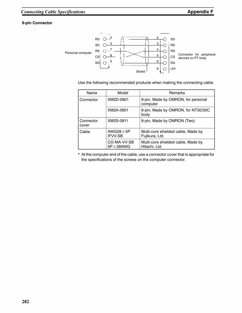
Appendix FConnecting Cable Specifications
282
9-pin Connector
Personal computer
Shield
Connector for peripheraldevices on PT body
2
3
7
8
5
RD
SD
RS
CS
SG
2
3
4
5
9
6
SD
RD
RS
CS
SG
+5V
Use the following recommended products when making the connecting cable.
Name Model Remarks
Connector XM2D-0901 9-pin, Made by OMRON, for personalcomputer
XM2A-0901 9-pin, Made by OMRON, for NT30/30Cbody
Connectorcover
XM2S-0911 9-pin, Made by OMRON (Two)
Cable AWG28×5PIFVV-SB
Multi-core shielded cable, Made byFujikura, Ltd.
CO-MA-VV-SB5P×28AWG
Multi-core shielded cable, Made byHitachi, Ltd.
* At the computer end of the cable, use a connector cover that is appropriate forthe specifications of the screws on the computer connector.

283
Appendix GConnection Using RS-232C/RS-422A Link
Adapters
By using the RS-232C/RS422A Link Adapter (NT-AL001), RS-232C can be converted to RS-422A, and commu-nications over a distance of up to 500 m is possible.
Connection is possibleusing theNT30/NT30C’sRS-232Cconnector or using theNT30/NT30’sRS-422A terminalblock. The methods differ in the way shown below.
Connection Method
S NT30/NT30’s RS-232C Connector
OMRON PC
RS-232C cable(2 m max.)
NT-AL001RS-232C/RS-422ALink Adapter
RS-422A cable(500 m max.)
NT-AL001RS-232C/RS-422ALink Adapter
RS-232C cable(2 m max.)
NT30/NT30C
S NT30/NT30’s RS-422A Terminal Block
OMRON PC
RS-232C cable(2 m max.)
NT-AL001RS-232C/RS-422ALink Adapter
RS-422A cable(500 m max.)
NT30/NT30C

Appendix GConnection Using RS-232C/RS-422A Link Adapters
284
Wiring
S RS-232C Cable Wiring
PT or PCAbbreviation Pin number
Connectorcover
RS-232Cinterface
Shield
NT-AL001
RS-232Cinterface
Connection not possible withNT30/NT30C.
Pin number Abbreviation
2
3
4
5
6
9
SD
RD
RS
CS
+5V
SG
SD
RD
RS
CS
+5V
SG
2
3
4
5
6
9
S RS-422A Cable Wiring
NT-AL001
RS-422A
Abbreviation Pin number
Shield
NT30/NT30C or NT-AL001Abbreviation
RS-422Aterminalblock
Connection not possiblewith NT30/NT30C.
Functionalground 1
3
4
5
6
SDB
SDA
RDB
RDA
SDB
SDA
RDB
RDA
Functionalground
Switch Settings
S DIP Switch Setting for the RS-232C/RS-422A Link Adapter
S DIP Switch Setting for the NT30/NT30C
(Settings for other DIP switch pins will depend on other factors.)
Set the NT30/NT30C’s memory switches for RS-422A communications.

285
Appendix HStandard Models
Programmable Terminals (PTs)
Model Specification
NT30-ST131-E Monochrome display, ivory
NT30-ST131B-E Monochrome display, black
NT30C-ST141-E STN color display, ivory
NT30C-ST141B-E STN color display, black
Host Link Units
Model Specification Applicable PC
C120-LK201-V1 CPU-mounting Unit with RS-232C connector C-seriesC1000HC120-LK202-V1 CPU-mounting Unit with RS-422A connector C1000HC2000
C200H-LK201-V1 Rack-mounting Unit with RS-232C connector for C200H C-seriesC200HSC200H-LK202-V1 Rack-mounting Unit with RS-422A connector for C200H C200HSC20HX/HG/HE(-Z)
C500H-LK201-V1 Features a selectable RS-232C/RS-422A connector C-series
C500-LK203 Rack-mounting Unit for C500 C1000HC2000H
C200-LK202-V1 Rack-mounting Unit with RS-422A connector for C200HC2000H
CV500-LK201 S Features an RS-232C connector and a selectableRS-232C/RS-422A connector
S Rack-mounting Unit for CVM1/CV
CVM1/CV-seriesCV500CV1000CV2000CVM1
Serial Communications Unit
Model Specification Applicable PC
CS1W-SCU21 Rack-mounting Unit with 2 RS-232C ports CS1-seriesCS1G/H
CompoBus/S Master Control Unit
Model Specification Applicable PC
SRM1-C02-V2 S RS-232C port (When communicating via RS-422A, connectthe CPM1-CIF11 RS-422A Adapter to the peripheral port.)
S Supports Host Link, 1:1 NT Link, and 1:N NT Linkcommunications
SRM1
CPU Units for Connection via Host Link
Model Specification Applicable PC
C20H/C28H/C40H/C60H Features a 9-pin connector for RS-232C connections C-seriesC20HC28HC40HC60H

Note
Appendix HStandard Models
286
Model Applicable PCSpecification
CPM1-10CDR-jCPM1-20CDR-jCPM1-30CDR-jCPM1-30CDR-j-V1CPM1A-10CDj-jCPM1A-20CDj-jCPM1A-30CDj-jCPM1A-40CDj-j
RS-232C adapter RS-422A adapter connected to theperipheral port.
C-seriesCPM1
CPM2A-30CDj-jCPM2A-40CDj-jCPM2A-60CDj-j
Features a 9-pin connector for RS-232C connections C-seriesCPM2A
CPM2C-10jjjjjj-jCPM2C-20jjjjjj-j
The communications connector contains the functionality ofboth a peripheral port and an RS-232C port. (Both of theseports can be made available with the CPM2C-CN111Connecting Cable. It can also be used just as a singleperipheral port or RS-232C port with the CS1W-CN114 orCN-118 Connecting Cables respectively.)
C-seriesCPM2C
CQM1-CPU21-ECQM1-CPU41-EV1CQM1-CPU42-EV1CQM1-CPU43-EV1CQM1-CPU44-EV1
Features a 9-pin connector for RS-232C connections C-seriesCQM1
CQM1H-CPU11CQM1H-CPU21CQM1H-CPU51CQM1H-CPU61
Features a 9-pin connector for RS-232C connections(The CQM1H-CPU11 has only a peripheral port.)
C-seriesCQM1H
C200HS-CPU21-EC200HS-CPU23-EC200HS-CPU31-EC200HS-CPU33-E
Features a connector for RS-232C connections(selectable/9-pin)
C200HS
C200HE-CPU32-(Z)E (*)C200HE-CPU32-(Z)E
Features a connector for RS-232C connections(selectable/9-pin)
C-seriesC200HE(-Z)
C200HG-CPU33-(Z)E (*)C200HG-CPU43-(Z)EC200HG-CPU53-(Z)E (*)C200HG-CPU63-(Z)E
Features a connector for RS-232C connections(selectable/9-pin)
C-seriesC200HG(-Z)
C200HX-CPU34-(Z)E (*)C200HX-CPU44-(Z)EC200HX-CPU54-(Z)E (*)C200HX-CPU65-(Z)EC200HX-CPU85-(Z)E
Features a connector for RS-232C connections(selectable/9-pin)
C-seriesC200HX(-Z)
CS1G-CPU42(-V1)CS1G-CPU43(-V1)CS1G-CPU44(-V1)CS1G-CPU45(-V1)
Features a 9-pin connector for RS-232C connections CS1-seriesCS1G
CS1H-CPU63(-V1)CS1H-CPU64(-V1)CS1H-CPU65(-V1)CS1H-CPU66(-V1)CS1H-CPU67(-V1)
Features a 9-pin connector for RS-232C connections CS1-seriesCS1H
CV500-CPU01-EV1CV1000-CPU01-EV1CV2000-CPU01-EV1CVM1-CPU01-EVjCVM1-CPU11-EVjCVM1-CPU21-EVj
Features a connector for RS-232C connections(selectable/9-pin)
CVM1/CV-seriesCV500CV1000CV2000CVM1
For CPU Units marked (*), a communications port is required.

Note
Appendix HStandard Models
287
CPU Units for Connection via NT Link
Name Model PC series
CPM1-10CDR-jCPM1-20CDR-jCPM1-30CDR-jCPM1-30CDR-j-V1CPM1A-10CDj-jCPM1A-20CDj-jCPM1A-30CDj-jCPM1A-40CDj-j
RS-232C adapter RS-422A adapter connected to theperipheral port.
C-seriesCPM1
CPM2A-30CDjj-jCPM2A-40CDjj-jCPM2A-60CDjj-j
Features a 9-pin connector for RS-232C connections C-seriesCPM2A
CPM2C-10jjjjjj-jCPM2C-20jjjjjj-j
Connect to the RS-232C connector on the CPM2C-CN111Connecting Cable that is connected to the communicationsport on the CPU Unit.
C-seriesCPM2C
CQM1-CPU41-ECQM1-CPU42-EV1CQM1-CPU43-EV1CQM1-CPU44-EV1
Features a 9-pin connector for RS-232C connections C-seriesCQM1
CQM1H-CPU21CQM1H-CPU51CQM1H-CPU61
Features a 9-pin connector for RS-232C connections C-seriesCQM1H
C200HS-CPU21-EC200HS-CPU23-EC200HS-CPU31-EC200HS-CPU33-E
Features a 9-pin connector for RS-232C connections C200HS
C200HE-CPU32-(Z)E (*)C200HE-CPU32-(Z)E
Features a connector for RS-232C connections(selectable/9-pin)
C-seriesC200HE(-Z)
C200HG-CPU33-(Z)E (*)C200HG-CPU43-(Z)EC200HG-CPU53-(Z)E (*)C200HG-CPU63-(Z)E
Features a connector for RS-232C connections(selectable/9-pin)
C-seriesC200HG(-Z)
C200HX-CPU34-(Z)E (*)C200HX-CPU44-(Z)EC200HX-CPU54-(Z)E (*)C200HX-CPU64-(Z)EC200HX-CPU65-(Z)EC200HX-CPU85-(Z)E
Features a connector for RS-232C connections(selectable/9-pin)
C-seriesC200HX(-Z)
CV500-CPU01-EV1CV1000-CPU01-EV1CV2000-CPU01-EV1
Features a 9-pin connector for RS-232C connections CV500CV1000CV2000
CVM1-CPU01-EV2CVM1-CPU11-EV2CVM1-CPU21-EV2
Features a 9-pin connector for RS-232C connections CVM1-series
For CPU Units marked (*), a communications port is required.

Appendix HStandard Models
288
RS-232C/RS-422C Link Adapter
Model Remarks
NT-AL001 Features a 9-pin connector for RS-232C connections and an 8-pin terminal block for RS-422Aconnections.
RS-232C Adapter and RS-422A Adapter
Model Remarks
CPM1-CIF01 Connects the RS-232C port on the NT30/NT30C to the peripheral port on the CPM1.
CPM1-CIF11 Connects the RS-422A port on the NT30/NT30C to the peripheral port on the CPM1.
Related Products for PTs
Name Model Remarks
NT Support ToolSystem Installer
NT-ZJ3MX1-EV3 Version 3.jFor Windows 95/98 on PC/AT or compatible computers.3.5-inch FD
NT-ZJCMX1-EV3 Version 3.jFor Windows 95/98 on PC/AT or compatible computers.CD-ROM
NT-ZJCMX1-EV4 Version 4.jFor Windows 95/98/NT4.0 on PC/AT or compatible computers.CD-ROM
Options NT30-CFL01 Replaceable Backlight (NT30)p
NT30C-CFL01 Replaceable Backlight (NT30C)
NT30-KBA01 Silicone rubber chemical-proof cover
NT30-KBA04 Reflection-suppressing protective sheets
C500-BAT08 Battery
* The DOS versions of the NT Support Tool (NT-ZA3PC/ZA3DV-Vj) and the System Installer (NT30-ZS3PC/ZS3DV-V1) can also be used.

Appendix HStandard Models
289
Parts Used for ConnectionCables with Connectors
Model Cable Length Applicable Unit Communication Method
XW2Z-200S 2 m Host Link Units with 25-pin Host Link
XW2Z-500S 5 m
pconnectors
XW2Z-200T 2 m Host Link Units and CPU Units with9 i
Host Link, NT Link
XW2Z-500T 5 m 9-pin connectors,
Connection Cables
Model Remarks
AWG28¢5PIFVV-SB
Multicore cable, manufactured by Fujikura, Ltd.
CO-MA-VV-SB5P¢28AWG
Multicore cable, manufactured by Hitachi Cable, Ltd.
Applicable Connectors
Name Model Remark
Connector XM2A-2501 25-pin, manufactured by OMRON
XM2A-0901 9-pin (plug), manufactured by OMRON
DE-9P 9-pin, manufactured by JAE
Connector Cover XM2S-2511 25-pin, manufactured by OMRONConnector CoverXM2S-0901 9-pin, manufactured by OMRON
DE-C1-J6 9-pin, manufactured by JAE
Printer Cable
Model Specification
NT-CNT121 Printer cable for half pitch (1.5 m), manufactured by OMRON
Connecting Cable for Peripheral Port of CS1-series PCs
Model Specification
CS1W-CN118 Manufactured by OMRON. (CS1-series peripheral port ↔ D-SUB, 9-pin, female connector)
Connecting Cable for CPM2C Communications Port
Model Specification
CPM2C-CN111 Manufactured by OMRON. (CPM2C communications port ↔ D-SUB, 9-pin, female connector;C-series peripheral port)
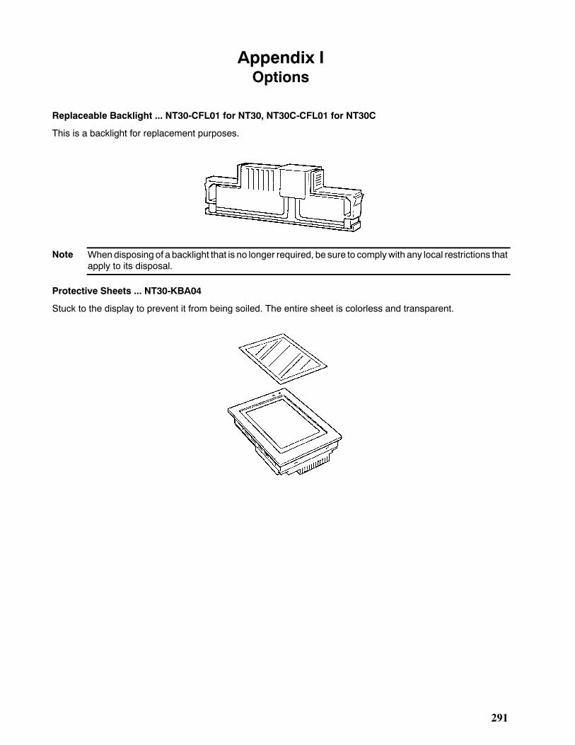
Note
291
Appendix IOptions
Replaceable Backlight ... NT30-CFL01 for NT30, NT30C-CFL01 for NT30C
This is a backlight for replacement purposes.
When disposing of a backlight that is no longer required, be sure to complywith any local restrictions thatapply to its disposal.
Protective Sheets ... NT30-KBA04
Stuck to the display to prevent it from being soiled. The entire sheet is colorless and transparent.

Request
Appendix IOptions
292
Chemical-proof Cover ... NT30-KBA01
Covers the front of the terminal and protects against all kinds of chemical agents. The entire sheet is milky whiteand is made of silicone rubber.
S The cover will not afford protection against some chemicals.S Since the cover is milky white, it makes the display slightly less clear.S This cover does not protect the connector between the NT30/30C and panel.
Battery ... C500-BAT08
This is a lithium battery used for memory backup.

293
Appendix JPC Memory Maps
OMRON C-Series Memory Map
Area IR Area HR Area AR Area LR AreaTimer/CounterArea
DM Area
Ladder type C20HC28HC40HC60H
0000 to 0255 0000 to 0099 0000 to 0027 0000 to 0063 0000 to 0511 0000 to 1999
C200HSC200HE(-Z)C200HG(-Z)C200HZ(-Z)
0000 to 0511 0000 to 0099 0000 to 0027 0000 to 0063 0000 to 0511 0000 to 66557000 to 9999
C1000H 0000 to 4095
C2000(H)CQM1 0000 to 0255 0000 to 0099 0000 to 0027 0000 to 0063 0000 to 0511 0000 to 6655
CQM1H 0000 to 6655(*)
CPM1CPM1A 0000 to 0019 0000 to 0019
0000 to 00150000 to 0015
0000 to 0127 0000 to 10236144 to 6655
CPM2ACPM2C
0000 to 00190200 to 0255 0000 to 0019
0000 to 00230000 to 0015
0000 to 0255 0000 to 6655
Flow type C1000HF 0000 to 0255 0000 to 0099 0000 to 0027 0000 to 0063 0000 to 0511 0000 to 4095
SRM1 0000 to 00190200 to 0255 0000 to 0019 0000 to 0015 0000 to 0015 0000 to 0127 0000 to 2021
6144 to 6655
* The area that can be used depends on the model of CPU Unit.
OMRON CV-Series Memory Map
Area CIO Area HR Area (*1) AR Area LR Area Timer/CounterArea DM Area
CV500CVM1-CPU01(-Vj)
0000 to 2555 0000 to 0511 0000 to 0511 0000 to 8191
CV1000CVM1-CPU11(-Vj)CV2000CVM1-CPU21(-Vj)
0000 to 2555 0000 to 0511 0000 to 1023 0000 to 9999(*2)
(*1) Included in the CIO area in the case of CVM1/CV-series PCs.(*2) This is the area that can be used with an NT30/30C. The DM area itself occupies the range 00000 to 24575.
OMRON CS1-Series CS1G/H Memory Map
Area CIO Area HR Area (*2) AR Area LR Area Timer/CounterArea DM Area
CS1GCS1H
0000 to 2555(*1)
0000 to 0511(*3)
0000 to 1023(*4)
0000 to 9999(*5)
(*1) This is the area that can be used with an NT30/30C. The CIO area itself occupies the range 00000 to 06655.(*2) The HR area cannot be used from the NT30/NT30C.(*3) This is the area that can be used with an NT30/30C. The AR area itself occupies the range 00000 to 00959.(*4) This is the area that can be used with an NT30/30C. The Timer/Counter area itself occupies the range 00000 to
04095.(*5) This is the area that can be used with an NT30/30C. The DM area itself occupies the range 00000 to 32767.

295
Appendix KSpecial Characters
English Character Codes
When using the terminal for the first time, the system program must be installed with pin 6 of SW2 ON to en-able English language messages to use the following codes.
Example: Hex code is represented by 30, decimal code by 48, and character by 0.
30 048
Code 20 and 32 in the table represents a space, as indicated by “SP”.
Hex Digits1st2nd
2- 3- 4- 5- 6- 7- 8- 9-
-0 20 SP 30 0 40 @ 50 P 60 ‘ 70 p 80 Ç 90 É32 48 64 80 96 112 128 144
-1 21 ! 31 1 41 A 51 Q 61 a 71 q 81 ü 91 æ33 49 65 81 97 113 129 145
-2 22 ” 32 2 42 B 52 R 62 b 72 r 82 é 92 Æ34 50 66 82 98 114 130 146
-3 23 # 33 3 43 C 53 S 63 c 73 s 83 â 93 ô35 51 67 83 99 115 131 147
-4 24 $ 34 4 44 D 54 T 64 d 74 t 84 ä 94 ö36 52 68 84 100 116 132 148
-5 25 % 35 5 45 E 55 U 65 e 75 u 85 à 95 ò37 53 69 85 101 117 133 149
-6 26 & 36 6 46 F 56 V 66 f 76 v 86 å 96 û38 54 70 86 102 118 134 150
-7 27 ’ 37 7 47 G 57 W 67 g 77 w 87 ç 97 ù39 55 71 87 103 119 135 151
-8 28 ( 38 8 48 H 58 X 68 h 78 x 88 ê 98 ÿ40 56 72 88 104 120 136 152
-9 29 ) 39 9 49 I 59 Y 69 i 79 y 89 ë 99 Ö41 57 73 89 105 121 137 153
-A 2A * 3A : 4A J 5A Z 6A j 7A z 8A è 9A Ü42 58 74 90 106 122 138 154
-B 2B + 3B ; 4B K 5B [ 6B k 7B 8B ï 9B ¢43 59 75 91 107 123 139 155
-C 2C , 3C < 4C L 5C \ 6C l 7C | 8C î 9C £44 60 76 92 108 124 140 156
-D 2D - 3D = 4D M 5D ] 6D m 7D 8D ì 9D ¥45 61 77 93 109 125 141 157
-E 2E . 3E > 4E N 5E ^ 6E n 7E ~ 8E Ä 9E Pt46 62 78 94 110 126 142 158
-F 2F / 3F ? 4F O 5F _ 6F o 7F 8F Å 9F ƒ47 63 79 95 111 127 143 159
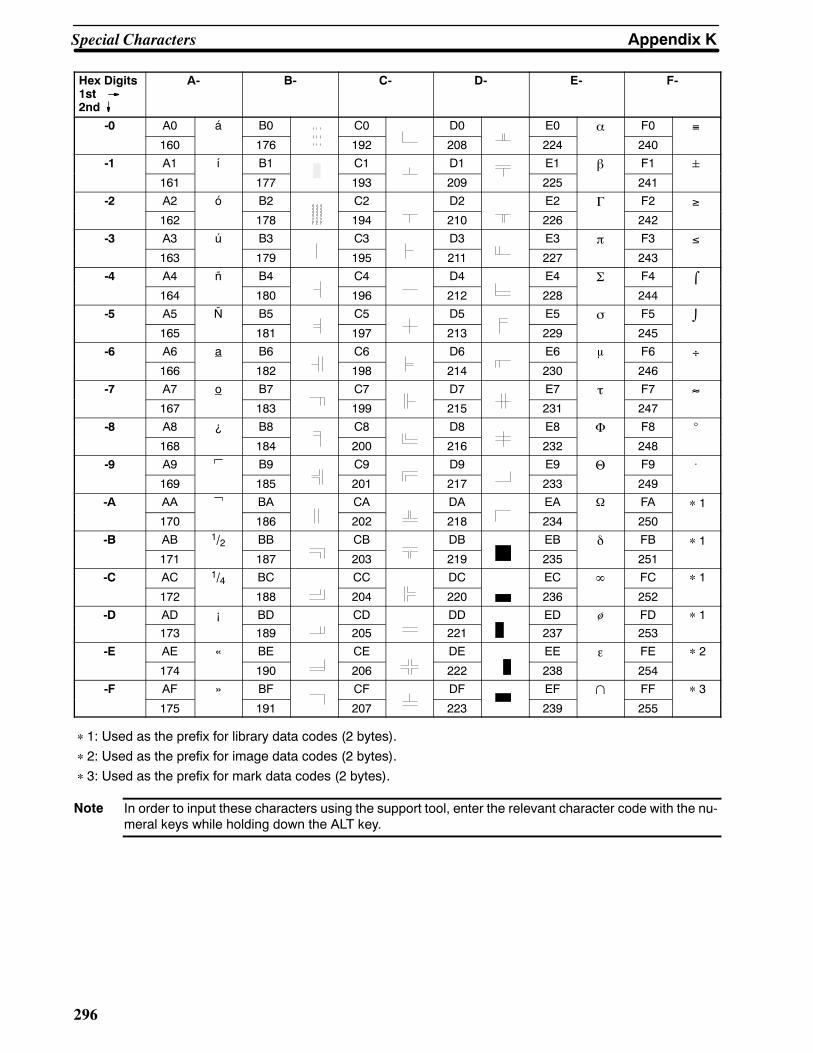
Note
Appendix KSpecial Characters
296
Hex Digits1st2nd
A- B- C- D- E- F-
-0 A0 á B0 C0 D0 E0 α F0 ≡160 176 192 208 224 240
-1 A1 í B1 C1 D1 E1 β F1 161 177 193 209 225 241
-2 A2 ó B2 C2 D2 E2 Γ F2 ≥162 178 194 210 226 242
-3 A3 ú B3 C3 D3 E3 π F3 ≤163 179 195 211 227 243
-4 A4 ñ B4 C4 D4 E4 Σ F4 ⌠164 180 196 212 228 244
-5 A5 Ñ B5 C5 D5 E5 σ F5 ⌡165 181 197 213 229 245
-6 A6 a B6 C6 D6 E6 μ F6 ÷166 182 198 214 230 246
-7 A7 o B7 C7 D7 E7 τ F7 ≈167 183 199 215 231 247
-8 A8 ¿ B8 C8 D8 E8 Φ F8 _
168 184 200 216 232 248
-9 A9 B9 C9 D9 E9 Θ F9 .
169 185 201 217 233 249
-A AA BA CA DA EA Ω FA ∗1
170 186 202 218 234 250
-B AB 1/2 BB CB DB EB δ FB ∗1
171 187 203 219 235 251
-C AC 1/4 BC CC DC EC ∞ FC ∗1
172 188 204 220 236 252
-D AD ¡ BD CD DD ED ø FD ∗1
173 189 205 221 237 253
-E AE « BE CE DE EE ε FE ∗2
174 190 206 222 238 254
-F AF » BF CF DF EF ∩ FF ∗3
175 191 207 223 239 255
∗1: Used as the prefix for library data codes (2 bytes).∗2: Used as the prefix for image data codes (2 bytes).∗3: Used as the prefix for mark data codes (2 bytes).
In order to input these characters using the support tool, enter the relevant character code with the nu-meral keys while holding down the ALT key.

297
Index
Aalarm history, displaying, 184
alarm list, 11allocated bits in bit memory table, 229displaying, 180example, 231using bit memory table, 230
allocations, bits and words, 9, 190
automatic reset function, 88
BB7A Interface Unitsinstallation, 66part names, 66settings, 67specifications, 65
B7A Units, 64operation, 185
backlightattributes, 135brightness, 256checking, 113color, 135, 241replacing, 252, 291service life, 256specifications, 258
batterieschecking voltage, 111errors, 250model number, 253, 292replacing, 253safety precautions, xvspecifications, 261
bit memory table, 140allocated bits for alarm list, 229used to display alarm list, 230used to switch screen display, 197
buzzer, 93, 134checking, 108controlling, 240specifications, 261
Ccablesmodels, 289parts required, 271preparing, 271procedure, 279
specifications, 281wiring, 281
with 25-pin connector, 25, 281with 9-pin connector, 26, 282
calendar, checking, 110
character string memory table, 11details, 136displaying contents, 201, 206setting the words, 203
character string setting, 171disabling character strings, 242entering character strings, 172functions, 171notification to PC, 227specifications, 260troubleshooting, 249
charactersEnglish character codes, 295enlargement, 128in character string memory table, 137smoothing, 128special, 295types, 126
cleaning, 255
clock function, 234displaying date and time, 234notification to PC, 238setting date and time, 235
communicationschecking, 106errors, 250functions, 130settings, 262host communications method, 85
specifications, 262using direct connection, 8
Communications Boards, connecting to, 47
comparison between NT30 and NT30C, 4
compatibility, 4
CompoBus/S Master Control Units, models, 285
connectorsmodels, 289specifications, 43, 271
control panel, 2
COPY key function, 160
cover, chemical-proof, 292
CPU Unitsconnecting to, 33models, 285, 287
cursor moving key function, 160

Index
298
Ddata, sent to the PC, 9
dimensions, 263
DIP switch settingsat startup, 74details, 18initializing screen data, 80precautions, xv, xvi
direct connection function, 8
displayscapacity, 259characters and figures, 126, 260checking LCD display, 107color, 124, 260display panel, 258elements, 10, 123, 259specifications, 260
flashing, 128, 130graphics, 260history recording function, 100, 134image data, 127, 260initializing history, 82, 241library data, 127, 260overview, 6protective sheets, 291reverse, 128, 130specifications, 258transparent, 125
Eenlargementof characters, 128of marks, 128specifications, 260
errorsat startup, 249communications, 250during operation, 250error messages, 249
external output function, 187
Ffeatures, 4
filling, 129
functionscharacter string setting, 171clock, 234communications, 130controllable functions, 240controlled by a PC, 9COPY key, 160cursor moving key, 160direct connection, 8display history initialization, 82, 241
display history recording, 100external output, 187I/O check, 103input key, 159numeral setting, 161overview, 4pop-up window, 173resume, 96SCREEN PRINT key, 160screen printing, 98, 241screen saver, 95, 188smoothing, 128stand alone, 157, 187summary diagram, 5
Ggraphicsattributes, 260color display, 129filling, 129flashing, 130reverse, 130types of, 129, 260
graphsbar graphs, 142broken line, 148displaying, 6trend graphs, 144troubleshooting, 248upgrading, 215
grounding, ground wire connection, 21
Hhardware, faults, 248
Host Linkcompatible PCs, 23, 40connecting to Communications Boards, 47connecting to CPU UnitsCS1-series, 37CVM1/CV-series, 46, 52
connecting to Host Link Units, 28, 48C-series, 44C120-LK201, 30, 51C120-LK202, 51C200H-LK201, 28C500-LK201, 29, 49C500-LK203, 30, 49CK500-LK201, 51CV500-LK201, 31CVM1/CV-series, 26, 45
connecting to PCsvia RS-232C, 23via RS-422A, 40
connectors, specifications, 43CPU Units, models, 285Host Link Units, models, 285operations, 190selecting baud rates, 86selecting communications ports, 87Serial Communications Units, 32models, 285
wiring, 43

Index
299
I--KI/Ocheck function, 103expanded, 64, 258
image datadescription, 126difference with library data, 127
indicatorschecking, 109display specifications, 258
initializationerrors, 250of display history data memory, 82of memory tables, 81of NT30/30C memory, 78of screen data, 79
input key function, 159
inspection, 255
installation, 19precautions, 19
key press soundselecting, 188setting, 92
Lladder program, precautions, xvi
lamps, 10, 151attributes, 151displaying, 216image library lamp function, 153image/library data, 217normal lamps, 151turning ON and OFF, 216
library datadescription, 127difference from image data, 127
Link Adapters, 265, 283models, 288
load local 1 (keyboard) attribute, 135
Mmaintenance, 252functions, 261
manuals, related, 14
marksdescription, 126enlargement, 128errors, 249
memoryerrors, 249initializing, 78PC memory maps, 293
memory switchesMemory Switch Menu, 84overview, 83setting, 84used to set communications, 83
memory tablesallocated words, 205bit, 140character string, 136copying entries, 212details, 201display, 205initializing, 81numeral, 138, 161
menu tree, 76
messages, 2
modelsbatteries, 253, 292cables, 289chemical-proof cover, 292CompoBus/S Master Control Units, 285connectors, 289CPU Units for Host Link, 285CPU Units for NT Link, 287Host Link Units, 285Programmable Terminals (PTs), 285protective sheets for displays, 291Serial Communications Units, 285
monitoring, production line status, 2
NNT Link, 9compatible PCs, 56connecting to a PC via, 56CPU Units, models, 287operations, 190specifications, communications, 262
numeral memory table, 10, 161details, 138displaying contents, 203, 206setting the words, 205troubleshooting, 249
numeral settingdetails, 161disabling numeral strings, 242entering numeric values, 167, 169functions, 161items to be set, 170notification to PC, 224numeric keys, 162thumbwheels, 163troubleshooting, 249types, 162
numeral setting screen, 135
numeric keys, 162allocation, 165assigned to input terminals, 187creating, 164entering numeric values, 167using settings, 165

Index
300
Ooperation panel, installation to, 19
operationsinternal processing, 267event processing, 269periodic processing, 267
operating environment, 257operation modes, 75overview, 2PC data exchange, 3procedure before operation, 13screen display, 3with System Menu, 77
Ppartsdescription of, 16required for Host Link connection, 42
PC memory maps, 293
PC switch settings, 27, 48RS-232C, 59RS-422A, 61
pop-up window function, 173display elements, 175opening and closing windows, 176temporary input fields, 177window screens, 175
power supplyconnection, 20precautions, xvispecifications, 257voltage, 255
precautions, xiiigeneral, xivsafety, xv
printerschecking, 112connecting, 63
Programmable Terminals (PTs)models, 285related products, 288setting status, checking the, 114
PT statusaccessing, 244notification, 194, 244reading, 245
PT Status Control Area, 12used to control NT30/30C status, 239used to switch screen display, 195
PT Status Notify Area, 12, 198
Rresume function, 96
RS-232Cconnecting to PCs, 23specifications, communications, 262
RS-422Aconnecting to PCs, 40specificationscommunications, 262terminal block, 43
Ssafety precautions, xv
screen dataconfirming, 100creating, 116errors, 249, 250initializing, 79, 250registering, 89transmitting, 122
SCREEN PRINT key function, 160
screen printing function, 98, 241specifications, 261
screen saver function, 95, 188
screensattributes, 134, 259classification, 131composition, 123consecutive, 132–133, 259currently displayed, 199display elements, 123history display, 259management, 123normal, 132, 259number of, 259overlapping, 132, 259registered numbers, 259registration, 259saving, 95, 188, 259special screen numbers, 124switching, 133using bit memory table, 197using PT Status Control Area, 195
types, 259window, 259
Serial Communications Units, 32models, 285
smoothing, 128, 260
specificationsB7A Interface Units, 65backlight, 258batteries, 261cables, 281communications, 262connectors, 271display, 258, 260

Index
301
general, 257performance, 258touch switches, 258
stand alone function, 157, 187
standard models, 285
startupDIP switch settings, 74procedure, 13starting operation, 91
statusaccessing, 244control, 191, 239notifying PC, 244reading, 245
Support Tool, connecting to, 21
system configuration, 7
system keypad, 135
system maintenance, 100
System Menudisplaying, 77functions of items, 78initializing screen data, 79installation, 74menu tree, 76operation flow, 74operation details, 77selecting menu items, 77
system programerrors, 250installation, 22
system settingschanging, 75details, 92
T--W
thumbwheels, 163entering numeric values, 169using settings, 169
time, checking, 110
touch switches, 10attributes, 156checking, 105details, 154displaying, 6, 218functions, 155notifying PC of status, 220precautions, xvispecifications, 258status, 220used as control panel, 2used to switch screens, 133
troubleshooting, 247
weight, 257
windows, opening and closing, 176, 241–242
wiringconnector cables, 281for OMRON Units, 271Host Link connections, 43

303
Revision History
A manual revision code appears as a suffix to the catalog number on the front cover of the manual.
Cat. No. V034-E1-5
Revision code
The following table outlines the changes made to the manual during each revision. Page numbers refer to theprevious version.
Revision code Date Revised content1 September 1995 Original production2 May 1996 Addition of notes on safety
3 August 1996 Revisions associated with model changeP.21
Correction of DIP switch descriptionP.20
Changes associated with modifications to screensP.69, P.73, P.74, P.75, P.76, P.77, P.78, P.79, P.80, P.81, P.82,P.83, P.84, P.91, P.93, P.95, P.96, P.98, P.103, P.105, P.106,P.107, P.108, P.109, P.110, P.111, P.112, P.113, P.114, P.115
Review of reference manuals, reference pages, and indexviii, P.12, P.15, P.16, P.26, P.36, P.85, P.89, P.90, P.92, P.111,P.118, P.135, P.161, P.174, P.193, P.199, P.206, P.207, P.209,P.221, P.222, P.231, P.242, P.245, P.253, P.263, P.264, P.269,P.288, P.313, P.314, P.315, P.316, P.317, P.318, P.319, P.320
4 January 1998 Addition of C200HX/HG/HE, CPM1 and SRM1
Correction of safety precautions
Changes of RS-232C wiring
5 January 2001 Addition of CS1 Series.
Overall correction and unification of terminology.
Partial rewrite for clarification.

V034-E1-5 ©2003 OMRON ELECTRONICS LLC Specifications subject to change without notice. Printed in the U.S.A.
OMRON ELECTRONICS LLC
1 Commerce DriveSchaumburg, IL 60173847.843.7900For US technical support or other inquiries: 800.556.6766
OMRON CANADA, INC.885 Milner AvenueToronto, Ontario M1B 5V8416.286.6465
OMRON ON-LINEGlobal - http://www.omron.comUSA -http://www.omron.com/oeiCanada -http://www.omron.ca