Embed Size (px)
Citation preview
NT1210 Introduction to Networking
Unit 7:Chapter 7, Wide Area NetworksChapter 7, Wide Area Networks
ObjectivesObjectives
Identify the major needs and stakeholders for y jcomputer networks and network applications.Identify the classifications of networks and how they are applied to various types of enterprises.Explain the functionality and use of typical network protocolsprotocols.Analyze network components and their primary functions in a typical data network from both logicalfunctions in a typical data network from both logical and physical perspectives.
2
ObjectivesObjectives
Differentiate among major types of LAN and WAN g j yptechnologies and specifications and determine how each is used in a data network.Explain basic security requirements for networks.Use network tools to monitor protocols and traffic characteristicscharacteristics.Use preferred techniques and necessary tools to troubleshoot common network problemstroubleshoot common network problems.Differentiate among WAN technologies available from service providersp
3
ObjectivesObjectives
Evaluate how WAN devices functionDefine and describe WAN protocolsEvaluate troubleshooting techniques for WANEvaluate troubleshooting techniques for WAN connections
4
Introducing Wide Area Networks: BasicIntroducing Wide Area Networks: Basic Telco Services
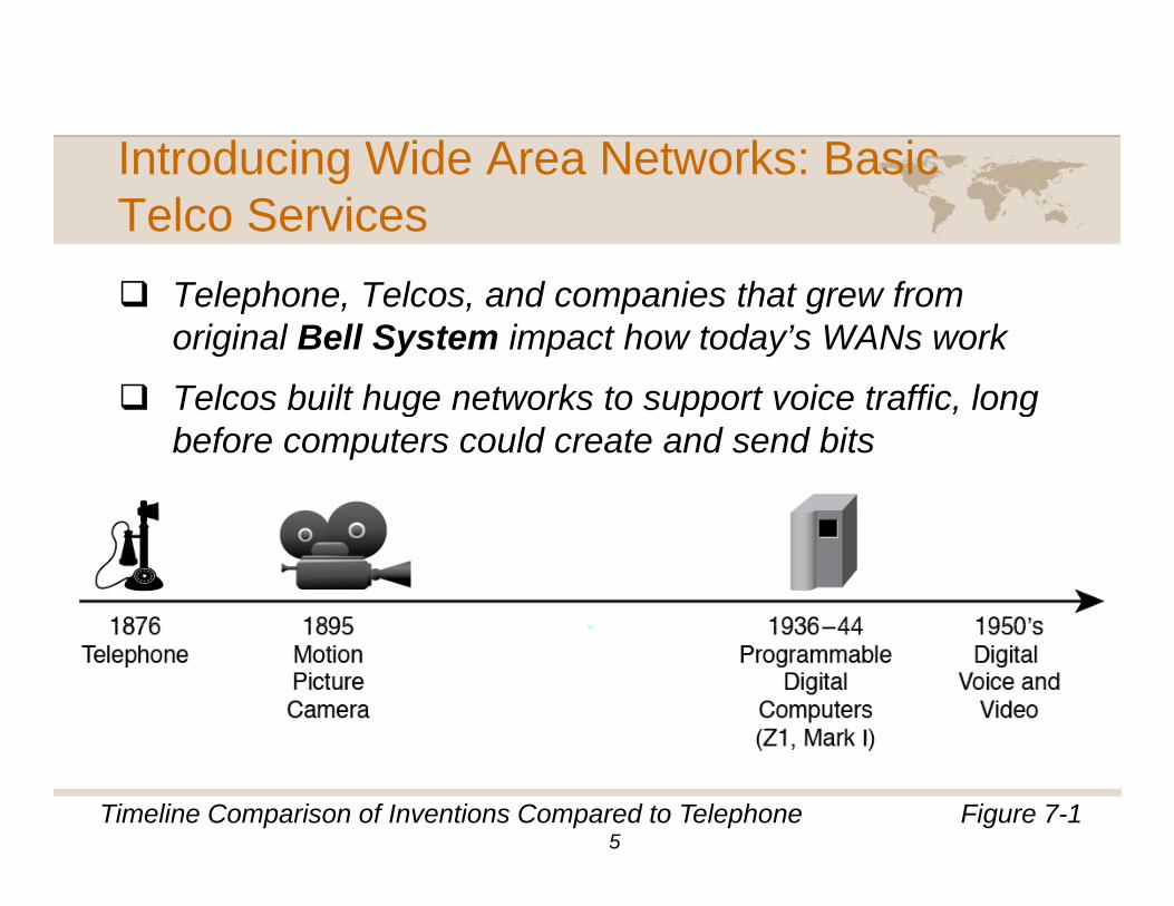
T l h T l d i th t fTelephone, Telcos, and companies that grew from original Bell System impact how today’s WANs work
Telcos built huge networks to support voice traffic longTelcos built huge networks to support voice traffic, long before computers could create and send bits
Figure 7-1Timeline Comparison of Inventions Compared to Telephone5
Introducing Wide Area Networks: BasicIntroducing Wide Area Networks: Basic Telco Services – Circuit Switching
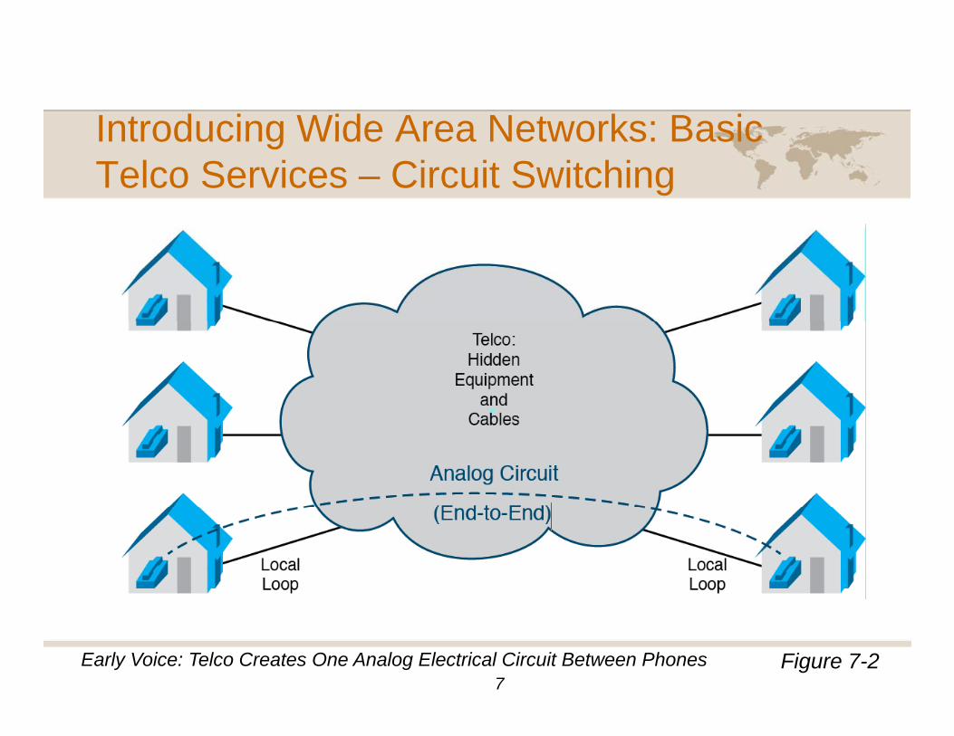
S it h d A l Ci it f V i I l d fSwitched Analog Circuits for Voice: In early days of telephones, voice call required one analog electrical circuit between two phonesp
Telco installed 2-wire cable into each home: Local loopOther end connected equipment sitting in nearby TelcoOther end connected equipment sitting in nearby Telco office: Central Office (CO)
When user called number, Telco created electrical circuit from one telephone to other (source to destination)
6
Introducing Wide Area Networks: BasicIntroducing Wide Area Networks: Basic Telco Services – Circuit Switching
Figure 7-2Early Voice: Telco Creates One Analog Electrical Circuit Between Phones7
Introducing Wide Area Networks: BasicIntroducing Wide Area Networks: Basic Telco Services – Circuit Switching
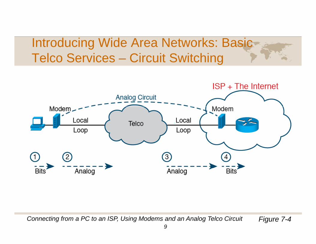
S it h d A l Ci it f D t T t fi t WANSwitched Analog Circuits for Data: To create first WAN connections, early computing devices had to act like telephonesp
One computer device would “make phone call” to other computer, encoding its bits using analog electrical signals
8
Introducing Wide Area Networks: BasicIntroducing Wide Area Networks: Basic Telco Services – Circuit Switching
Figure 7-4Connecting from a PC to an ISP, Using Modems and an Analog Telco Circuit9
Introducing Wide Area Networks: BasicIntroducing Wide Area Networks: Basic Telco Services – Circuit Switching
B i i id 20th t T l t f dBeginning mid-20th century Telcos transformedInvention and commercialization of computers: Started with few computers being rare and unusual to world where mostfew computers being rare and unusual to world where most companies owned computers
Migration from Telcos as government monopolies to free-market competition: Governments started removing monopolymarket competition: Governments started removing monopoly status from different parts of Telcos’ business so allowed competition
C fComputerization of Telco’s own network: Revolutionized how Telco built its internal network to create better services at lower cost
10
Introducing Wide Area Networks: BasicIntroducing Wide Area Networks: Basic Telco Services – Circuit Switching
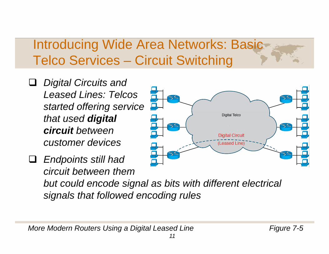
Di it l Ci it dDigital Circuits and Leased Lines: Telcos started offering service gthat used digital circuit between customer devicescustomer devices
Endpoints still had circuit between them but could encode signal as bits with different electrical signals that followed encoding rules
Figure 7-5More Modern Routers Using a Digital Leased Line11
Introducing Wide Area Networks: BasicIntroducing Wide Area Networks: Basic Telco Services – Circuit Switching
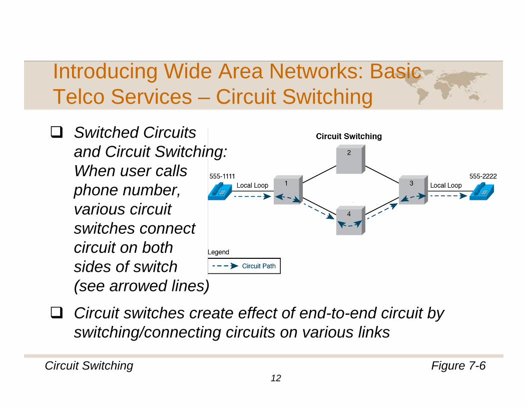
S it h d Ci itSwitched Circuits and Circuit Switching: When user calls phone number, various circuit switches connectswitches connect circuit on both sides of switch ( d li )(see arrowed lines)
Circuit switches create effect of end-to-end circuit by switching/connecting circuits on various linksswitching/connecting circuits on various links
Figure 7-6Circuit Switching12
Introducing Wide Area Networks: BasicIntroducing Wide Area Networks: Basic Telco Services – Circuit Switching
T t it h d i it S it h d tTo create switched circuits: Switches and customer devices (telephones and modems) use signaling to setup and tear down circuitp
Signaling messages allow switches to choose which switch-to-switch links (trunks) to use for particular call
13

Introducing Wide Area Networks: BasicIntroducing Wide Area Networks: Basic Telco Services – Circuit Switching
Ci it C i ti th b t t d i tCircuit: Communication path between two endpoints
Circuit Switching: Logic used by Telco network and devices called “circuit switches” that allows them todevices called circuit switches that allows them to switch circuits in and out of different physical trunks to create end-to-end circuit through network
Switched Circuit: End-to-end circuit through Telco that changes over time because user calls number, hangs up calls another number and so onup, calls another number, and so on
Dedicated Circuit (leased line): Circuit between two specific devices Telco never takes downspecific devices Telco never takes down
14
Introducing Wide Area Networks: BasicIntroducing Wide Area Networks: Basic Telco Services – Packet Switching
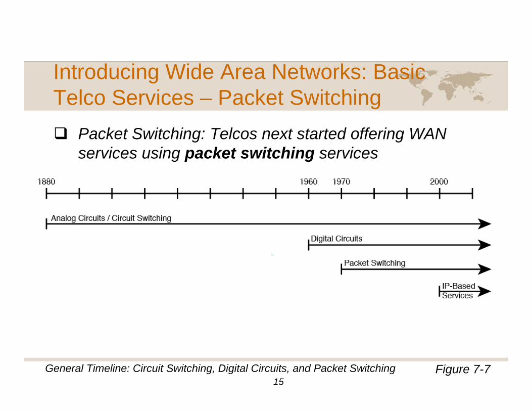
P k t S it hi T l t t t d ff i WANPacket Switching: Telcos next started offering WAN services using packet switching services
Figure 7-7General Timeline: Circuit Switching, Digital Circuits, and Packet Switching15
Introducing Wide Area Networks: BasicIntroducing Wide Area Networks: Basic Telco Services – Packet Switching
All t d i d di t ti t WAN iAll customer devices need direct connection to WAN via circuit to packet switching service
Customers: All devices can send data to every otherCustomers: All devices can send data to every other device connected to packet switched service
Telco (service provider): Must look at meaning of bits inTelco (service provider): Must look at meaning of bits in customer’s headers and make forwarding decision per packet
16
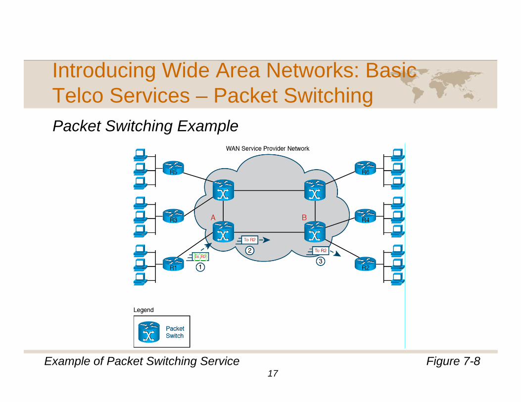
Introducing Wide Area Networks: BasicIntroducing Wide Area Networks: Basic Telco Services – Packet SwitchingPacket Switching ExamplePacket Switching Example
Figure 7-8Example of Packet Switching Service17

Introducing Wide Area Networks: Routers
C t LAN t WANConnect LANs to WANs
Figure 7-9Layer 3 IP Forwarding Logic18
Introducing Wide Area Networks: Routers
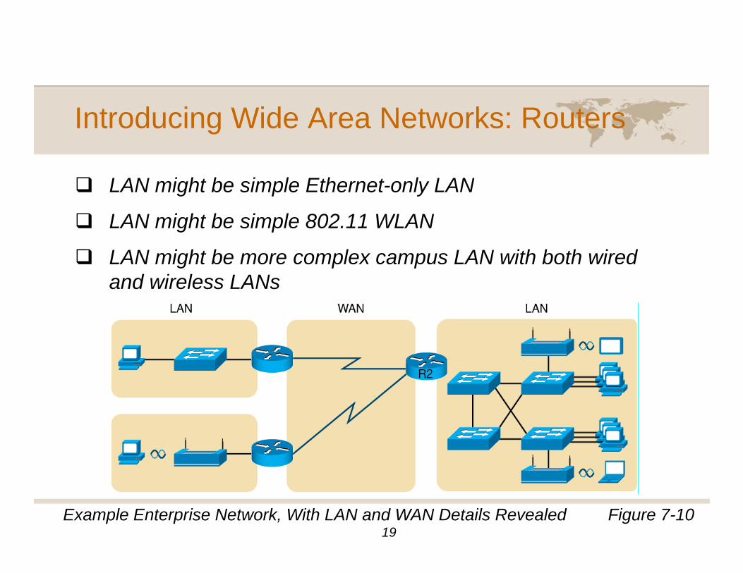
LAN i ht b i l Eth t l LANLAN might be simple Ethernet-only LAN
LAN might be simple 802.11 WLAN
LAN i ht b l LAN ith b th i dLAN might be more complex campus LAN with both wired and wireless LANs
Figure 7-10Example Enterprise Network, With LAN and WAN Details Revealed19
Introducing Wide Area Networks: Routers
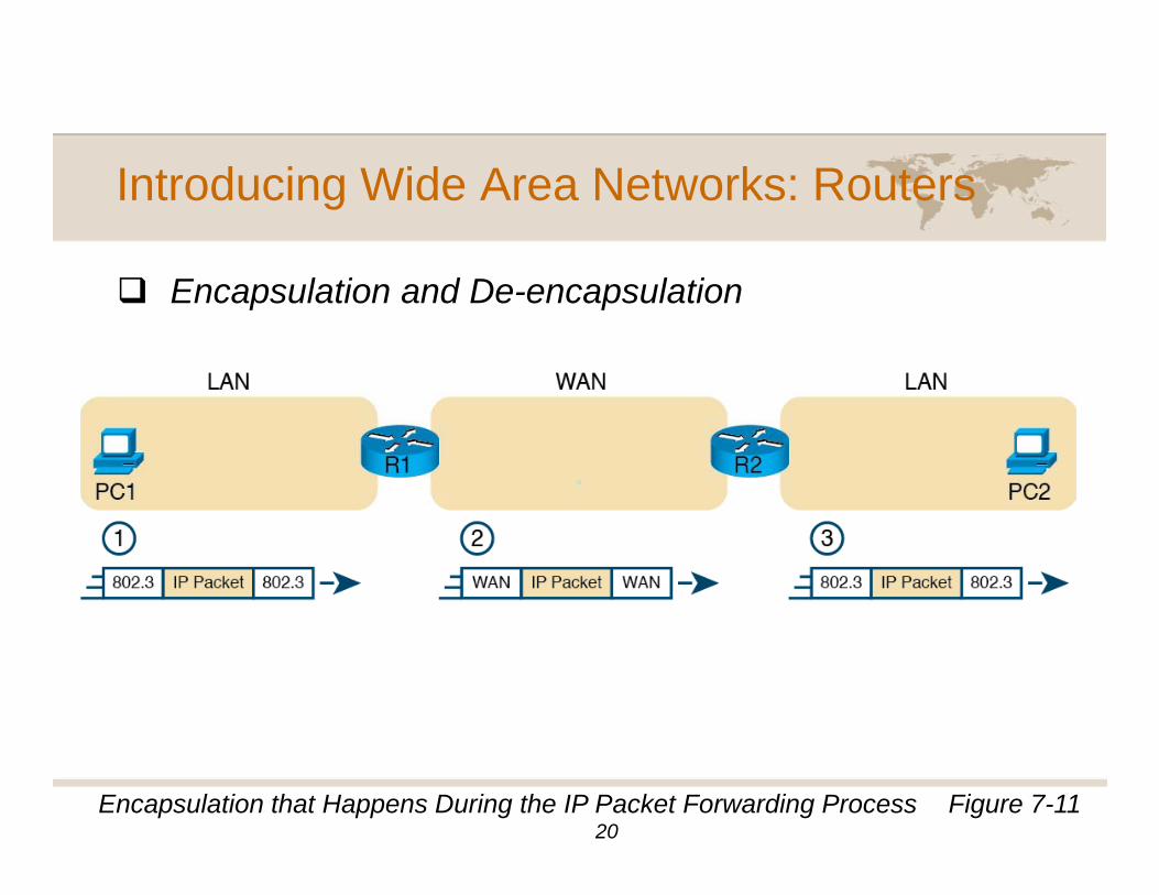
E l ti d D l tiEncapsulation and De-encapsulation
Figure 7-11Encapsulation that Happens During the IP Packet Forwarding Process20
Introducing Wide Area Networks: Topologies
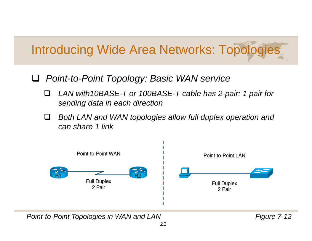
P i t t P i t T l B i WAN iPoint-to-Point Topology: Basic WAN serviceLAN with10BASE-T or 100BASE-T cable has 2-pair: 1 pair for sending data in each directionsending data in each direction
Both LAN and WAN topologies allow full duplex operation and can share 1 link
Figure 7-12Point-to-Point Topologies in WAN and LAN21
Introducing Wide Area Networks: Topologies
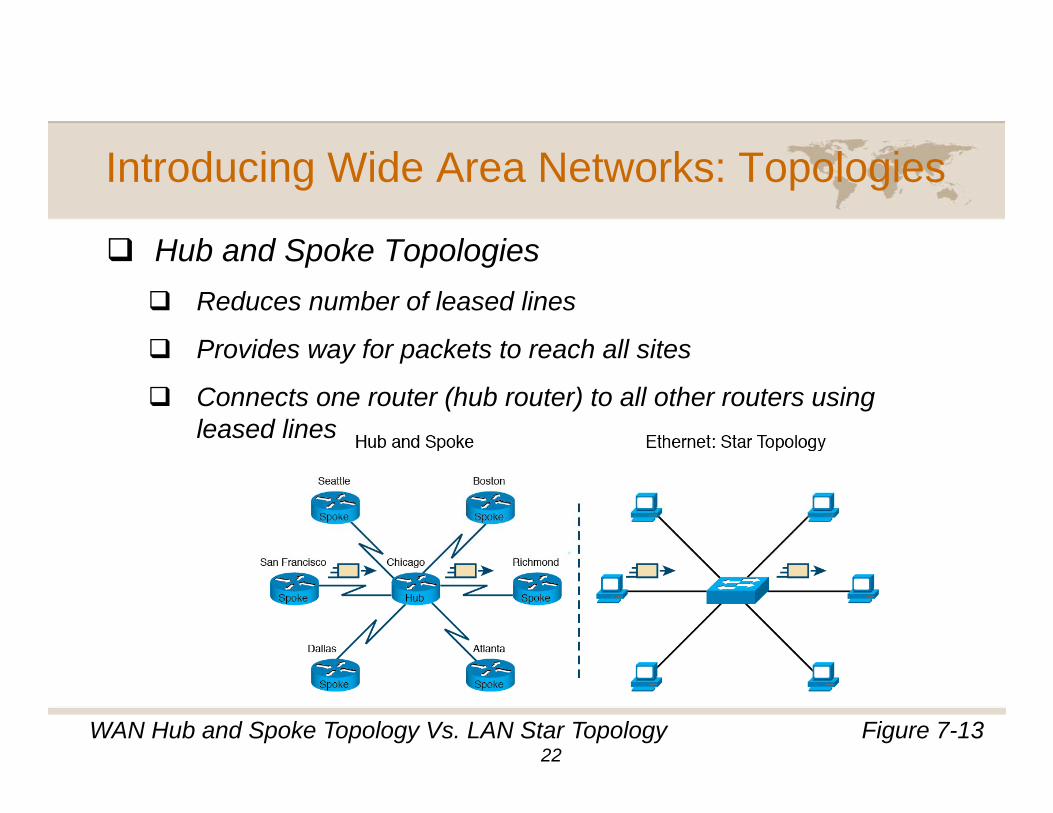
Hub and Spoke TopologiesHub and Spoke TopologiesReduces number of leased lines
Provides way for packets to reach all sitesProvides way for packets to reach all sites
Connects one router (hub router) to all other routers using leased lines
Figure 7-13WAN Hub and Spoke Topology Vs. LAN Star Topology22
Introducing Wide Area Networks: Topologies
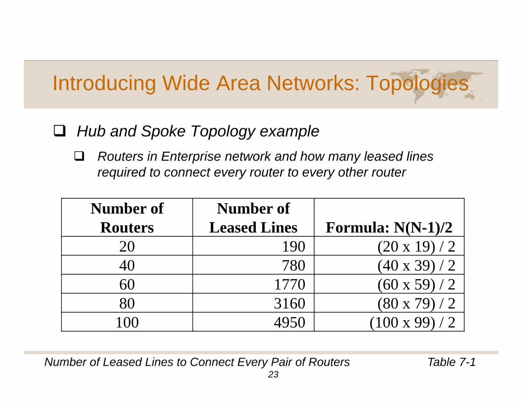
H b d S k T l lHub and Spoke Topology exampleRouters in Enterprise network and how many leased lines required to connect every router to every other routerrequired to connect every router to every other router
Number of Routers
Number of Leased Lines Formula: N(N 1)/2Routers Leased Lines Formula: N(N-1)/2
20 190 (20 x 19) / 2 40 780 (40 x 39) / 260 1770 (60 x 59) / 280 3160 (80 x 79) / 2100 4950 (100 x 99) / 2
Table 7-1Number of Leased Lines to Connect Every Pair of Routers
( )
23
Introducing Wide Area Networks: Topologies
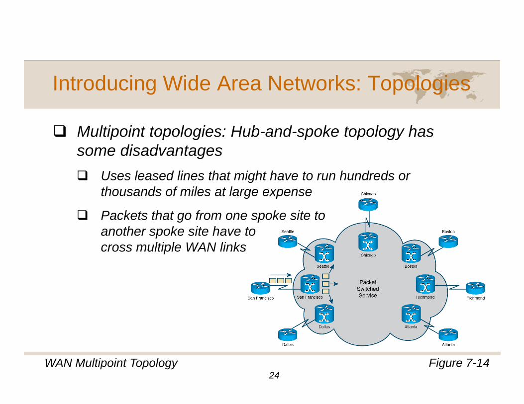
M lti i t t l i H b d k t l hMultipoint topologies: Hub-and-spoke topology has some disadvantages
Uses leased lines that might have to run hundreds orUses leased lines that might have to run hundreds or thousands of miles at large expense
Packets that go from one spoke site to th k it h tanother spoke site have to
cross multiple WAN links
Figure 7-14WAN Multipoint Topology24
Understanding Leased Line WAN Links
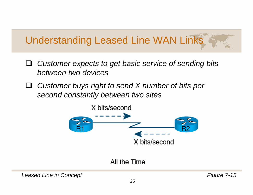
C t t t t b i i f di bitCustomer expects to get basic service of sending bits between two devices
Customer buys right to send X number of bits perCustomer buys right to send X number of bits per second constantly between two sites
Figure 7-15Leased Line in Concept25
Understanding Leased Line WAN Links
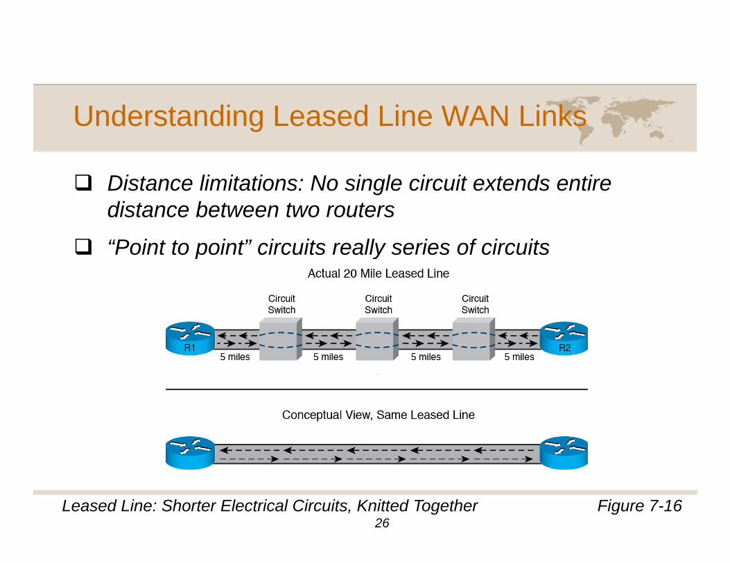
Di t li it ti N i l i it t d tiDistance limitations: No single circuit extends entire distance between two routers
“Point to point” circuits really series of circuitsPoint to point circuits really series of circuits
Figure 7-16Leased Line: Shorter Electrical Circuits, Knitted Together26
Understanding Leased Line WAN Links
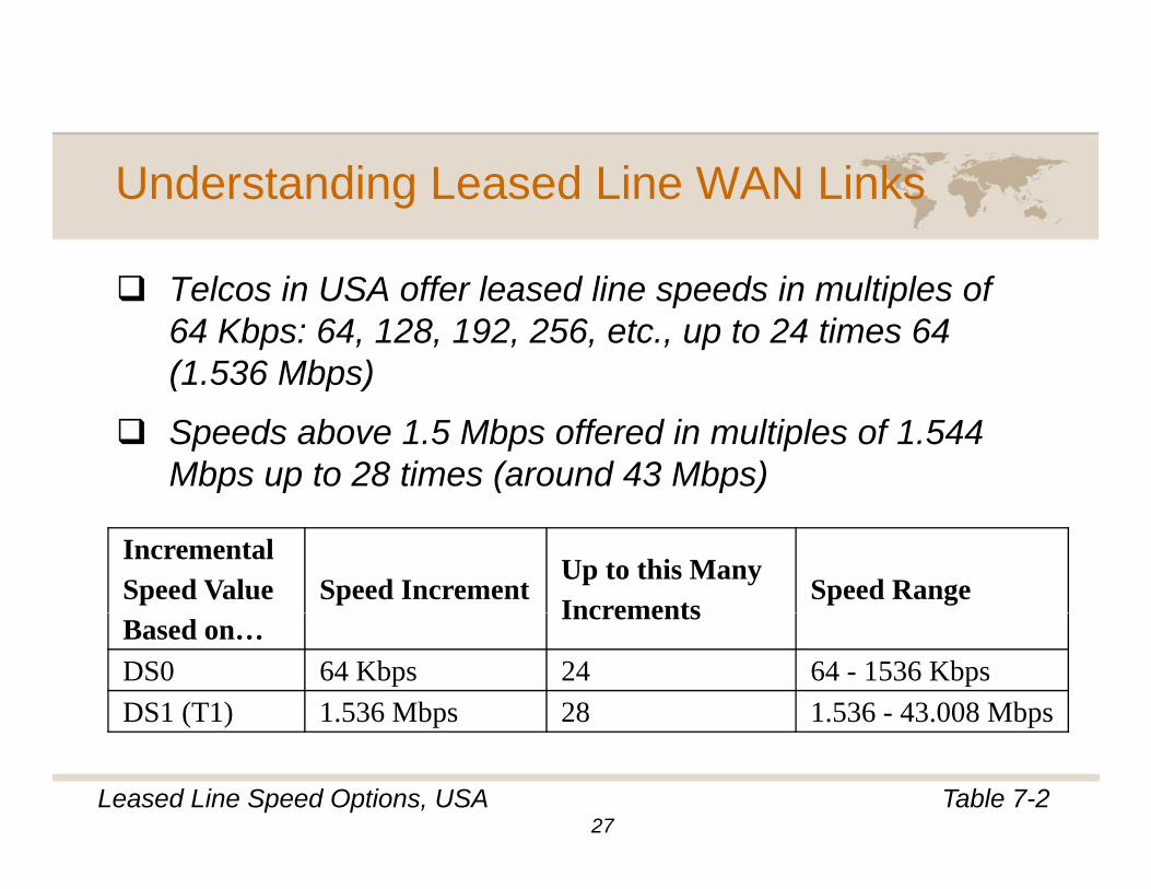
T l i USA ff l d li d i lti l fTelcos in USA offer leased line speeds in multiples of 64 Kbps: 64, 128, 192, 256, etc., up to 24 times 64 (1.536 Mbps)( p )
Speeds above 1.5 Mbps offered in multiples of 1.544 Mbps up to 28 times (around 43 Mbps)
Incremental Speed Value Speed Increment
Up to this Many Increments
Speed RangeBased on…
Increments
DS0 64 Kbps 24 64 - 1536 Kbps DS1 (T1) 1.536 Mbps 28 1.536 - 43.008 Mbps
Table 7-2Leased Line Speed Options, USA27
( ) p p
Understanding Leased Line WAN Links
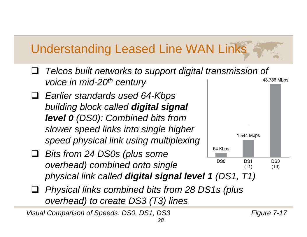
Telcos built networks to support digital transmission ofTelcos built networks to support digital transmission of voice in mid-20th centuryEarlier standards used 64-Kbps b ildi bl k ll d di it l i lbuilding block called digital signallevel 0 (DS0): Combined bits from slower speed links into single higher p g gspeed physical link using multiplexingBits from 24 DS0s (plus some overhead) combined onto singleoverhead) combined onto single physical link called digital signal level 1 (DS1, T1)Physical links combined bits from 28 DS1s (plus y (poverhead) to create DS3 (T3) lines
Figure 7-17Visual Comparison of Speeds: DS0, DS1, DS328
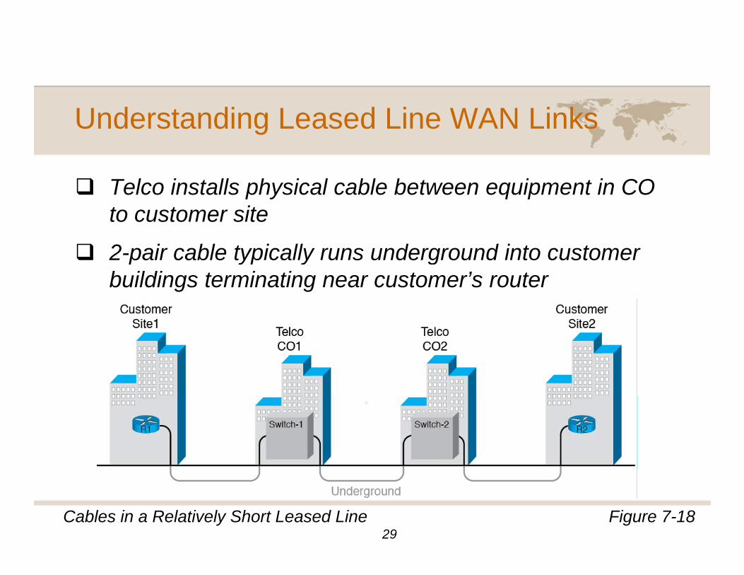
Understanding Leased Line WAN Links
T l i t ll h i l bl b t i t i COTelco installs physical cable between equipment in CO to customer site
2 pair cable typically runs underground into customer2-pair cable typically runs underground into customer buildings terminating near customer’s router
Figure 7-18Cables in a Relatively Short Leased Line29
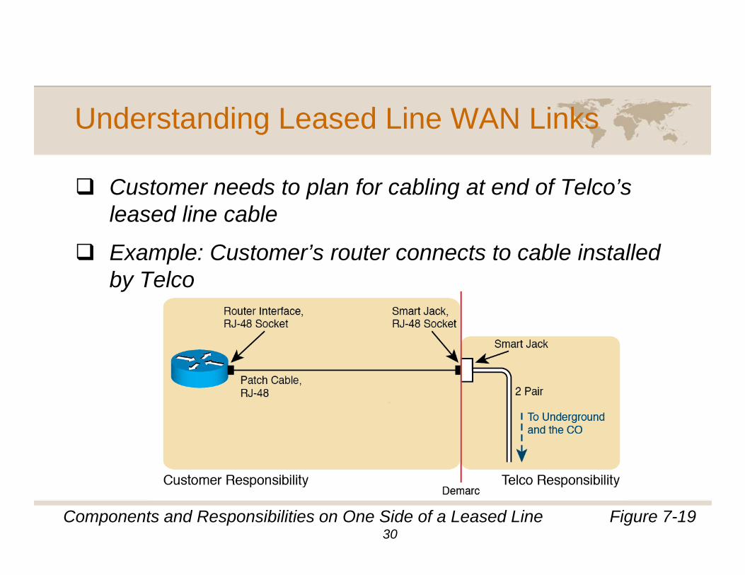
Understanding Leased Line WAN Links
C t d t l f bli t d f T l ’Customer needs to plan for cabling at end of Telco’s leased line cable
Example: Customer’s router connects to cable installedExample: Customer s router connects to cable installed by Telco
Figure 7-19Components and Responsibilities on One Side of a Leased Line30
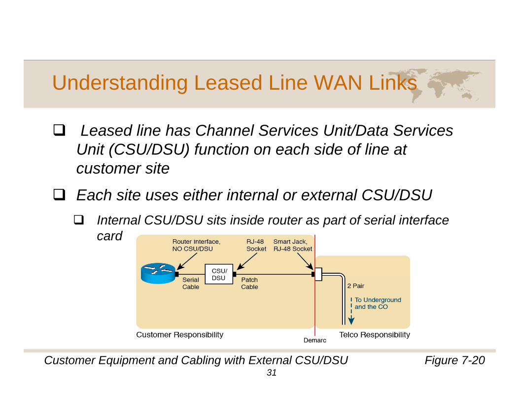
Understanding Leased Line WAN Links
L d li h Ch l S i U it/D t S iLeased line has Channel Services Unit/Data Services Unit (CSU/DSU) function on each side of line at customer site
Each site uses either internal or external CSU/DSU Internal CSU/DSU sits inside router as part of serial interface pcard
Figure 7-20Customer Equipment and Cabling with External CSU/DSU31
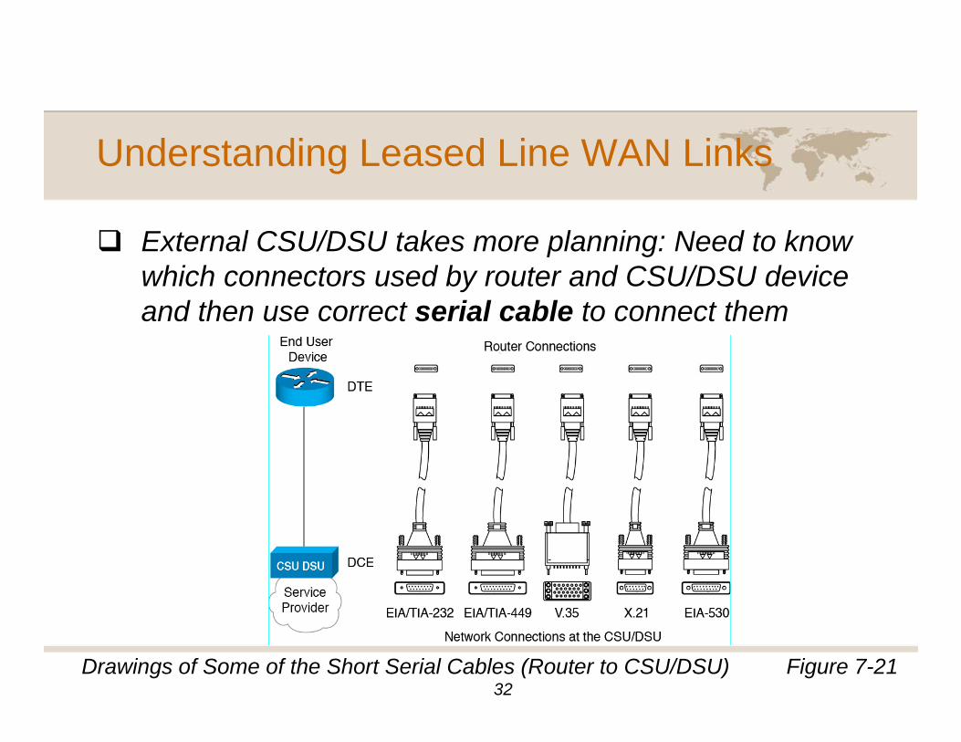
Understanding Leased Line WAN Links
E t l CSU/DSU t k l i N d t kExternal CSU/DSU takes more planning: Need to know which connectors used by router and CSU/DSU device and then use correct serial cable to connect them
Figure 7-21Drawings of Some of the Short Serial Cables (Router to CSU/DSU)32
Understanding Leased Line WAN Links
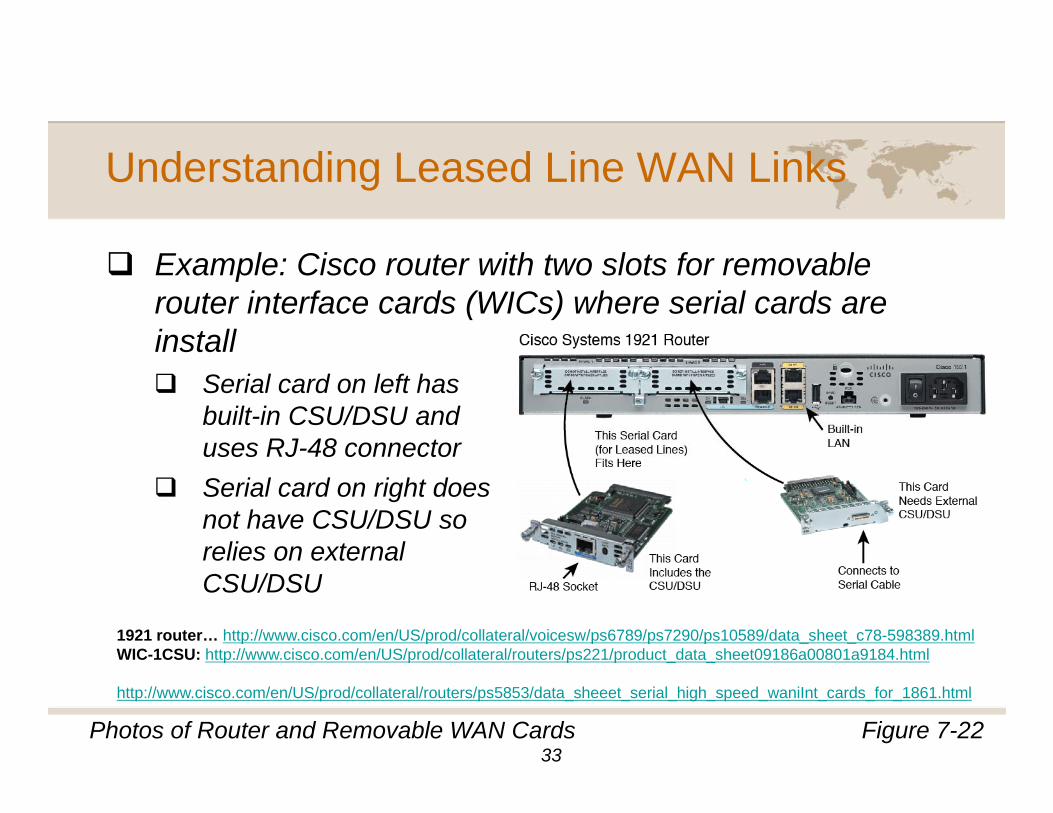
E l Ci t ith t l t f blExample: Cisco router with two slots for removable router interface cards (WICs) where serial cards are install
Serial card on left has built-in CSU/DSU and uses RJ-48 connectorSerial card on right does not have CSU/DSU so relies on external e es o e te aCSU/DSU
1921 router… http://www.cisco.com/en/US/prod/collateral/voicesw/ps6789/ps7290/ps10589/data_sheet_c78-598389.htmlWIC-1CSU: http://www.cisco.com/en/US/prod/collateral/routers/ps221/product_data_sheet09186a00801a9184.html
Figure 7-22Photos of Router and Removable WAN Cards
http://www.cisco.com/en/US/prod/collateral/routers/ps5853/data_sheeet_serial_high_speed_waniInt_cards_for_1861.html
33
Understanding Leased Line WAN Links
K t f i t lli l d liKey steps for installing leased lines1. Order leased line from Telco; include specs on line speed, cable
connectors required, and exact location where cable should be installed (address, floor, identifying information for exact room)
2. Install router and serial interface cards in router as needed by leased line
3. If interface card does not have internal CSU/DSU, choose CSU/DSU and matching cable
4. Physically connect all cablesy y5. Configure devices (beyond scope of this chapter)
34
Break
Take 10
35
Understanding Leased Line WAN Links:Understanding Leased Line WAN Links: Multiplexing
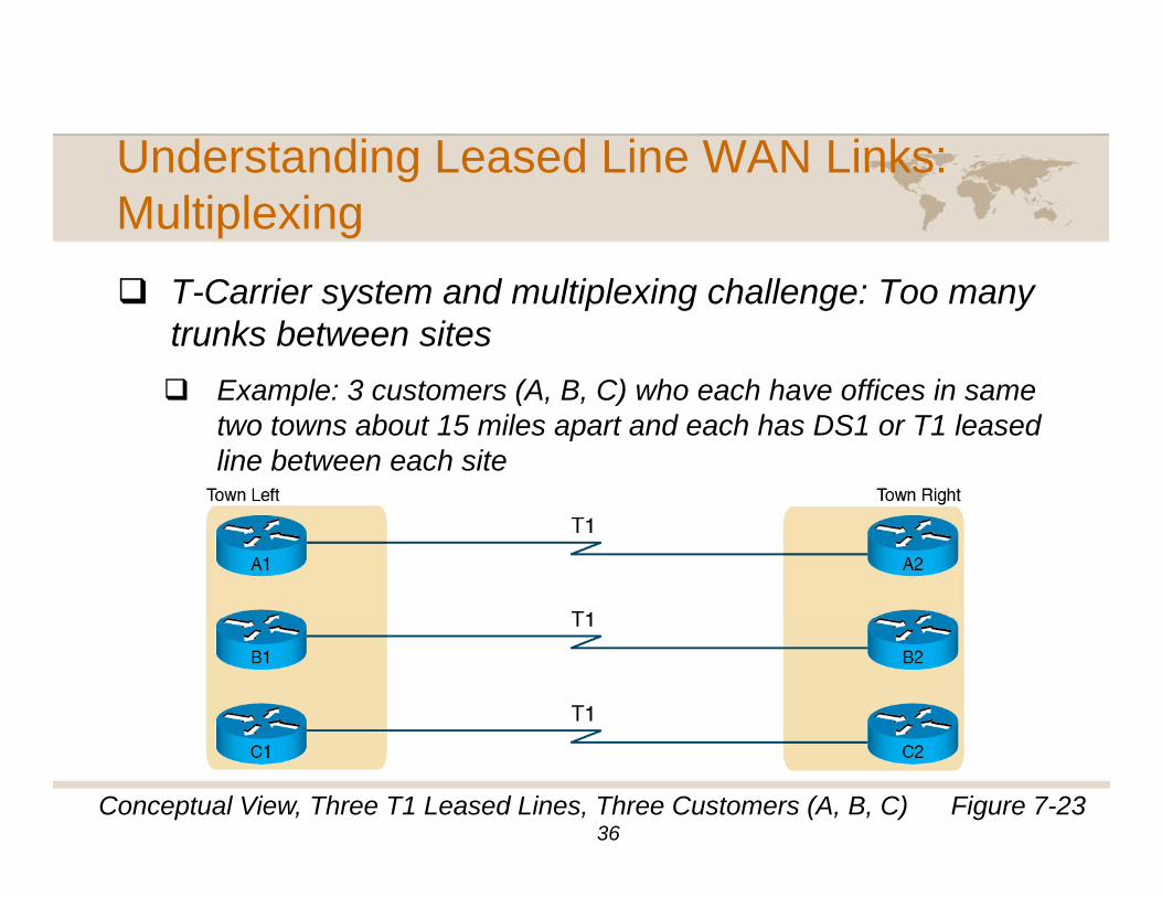
T C i t d lti l i h ll TT-Carrier system and multiplexing challenge: Too many trunks between sites
Example: 3 customers (A B C) who each have offices in sameExample: 3 customers (A, B, C) who each have offices in same two towns about 15 miles apart and each has DS1 or T1 leased line between each site
Figure 7-23Conceptual View, Three T1 Leased Lines, Three Customers (A, B, C)36
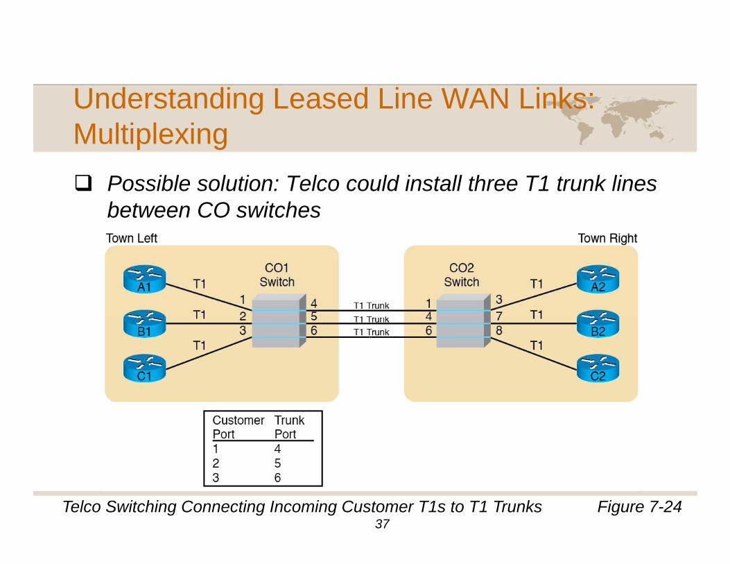
Understanding Leased Line WAN Links:Understanding Leased Line WAN Links: Multiplexing
P ibl l ti T l ld i t ll th T1 t k liPossible solution: Telco could install three T1 trunk lines between CO switches
Figure 7-24Telco Switching Connecting Incoming Customer T1s to T1 Trunks37
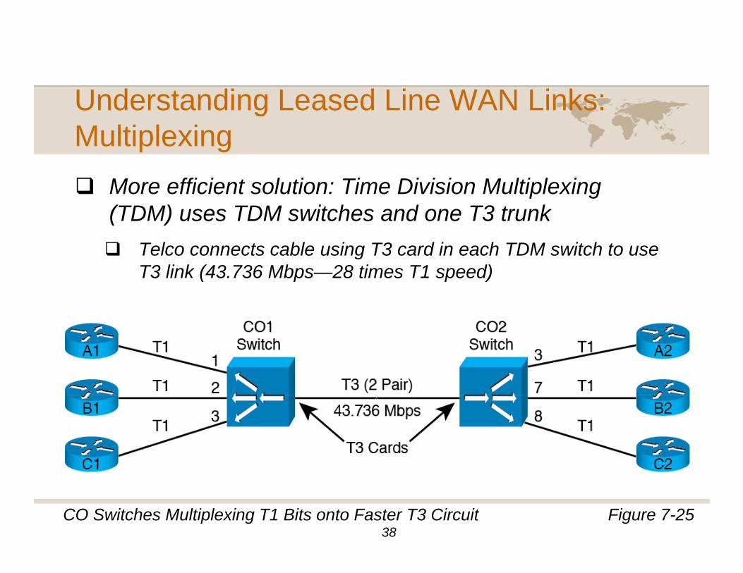
Understanding Leased Line WAN Links:Understanding Leased Line WAN Links: Multiplexing
M ffi i t l ti Ti Di i i M lti l iMore efficient solution: Time Division Multiplexing (TDM) uses TDM switches and one T3 trunk
Telco connects cable using T3 card in each TDM switch to useTelco connects cable using T3 card in each TDM switch to use T3 link (43.736 Mbps—28 times T1 speed)
Figure 7-25CO Switches Multiplexing T1 Bits onto Faster T3 Circuit38
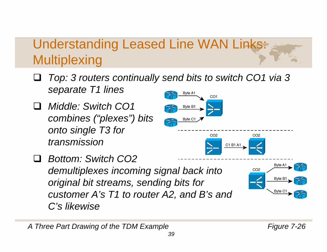
Understanding Leased Line WAN Links:Understanding Leased Line WAN Links: Multiplexing
Top: 3 routers continually send bits to switch CO1 via 3Top: 3 routers continually send bits to switch CO1 via 3 separate T1 lines
Middle: Switch CO1 combines (“plexes”) bits onto single T3 for transmissiontransmission
Bottom: Switch CO2 demultiplexes incoming signal back intodemultiplexes incoming signal back into original bit streams, sending bits for customer A’s T1 to router A2, and B’s and C’s likewiseC s likewise
Figure 7-26A Three Part Drawing of the TDM Example39
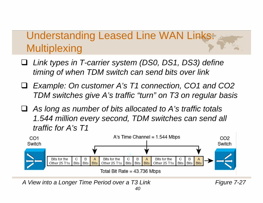
Understanding Leased Line WAN Links:Understanding Leased Line WAN Links: Multiplexing
Link types in T-carrier system (DS0 DS1 DS3) defineLink types in T-carrier system (DS0, DS1, DS3) define timing of when TDM switch can send bits over link
Example: On customer A’s T1 connection, CO1 and CO2 p ,TDM switches give A’s traffic “turn” on T3 on regular basis
As long as number of bits allocated to A’s traffic totals 1.544 million every second, TDM switches can send all traffic for A’s T1
Figure 7-27A View into a Longer Time Period over a T3 Link40
Understanding Leased Line WAN Links:Understanding Leased Line WAN Links: Multiplexing
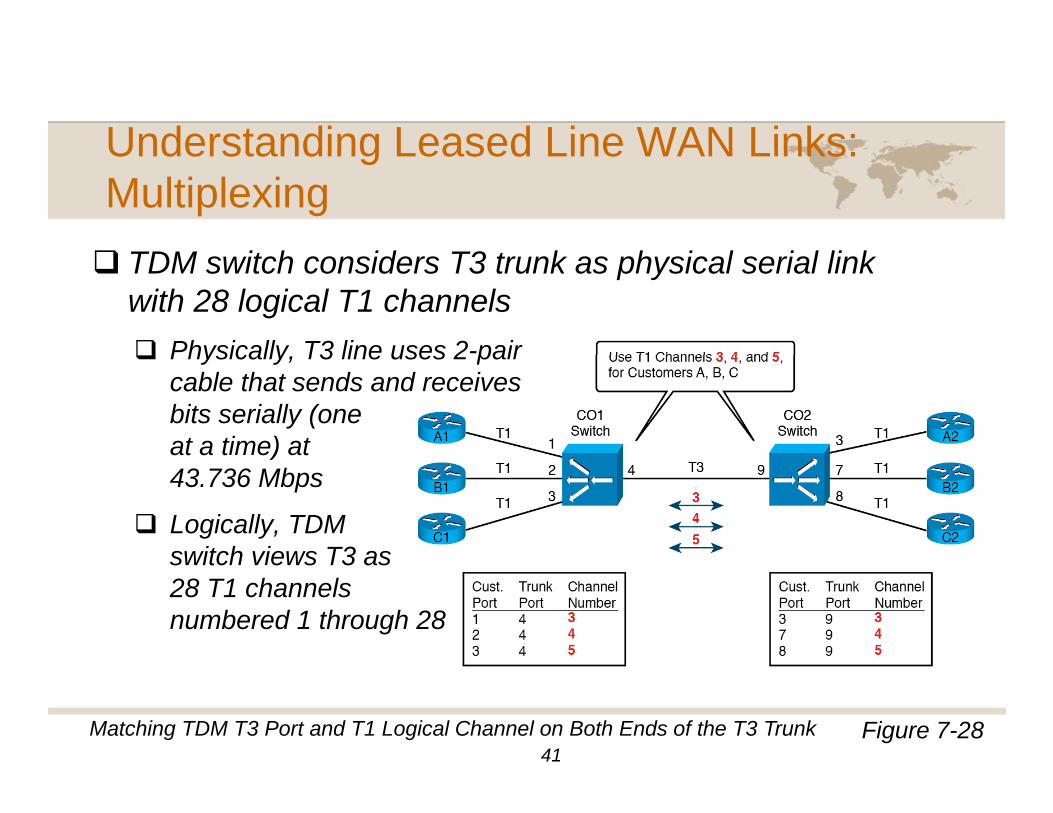
TDM it h id T3 t k h i l i l li kTDM switch considers T3 trunk as physical serial link with 28 logical T1 channels
Physically T3 line uses 2-pairPhysically, T3 line uses 2 pair cable that sends and receives bits serially (one at a time) at )43.736 Mbps
Logically, TDM switch views T3 asswitch views T3 as 28 T1 channels numbered 1 through 28
Figure 7-28Matching TDM T3 Port and T1 Logical Channel on Both Ends of the T3 Trunk41
Understanding Leased Line WAN Links
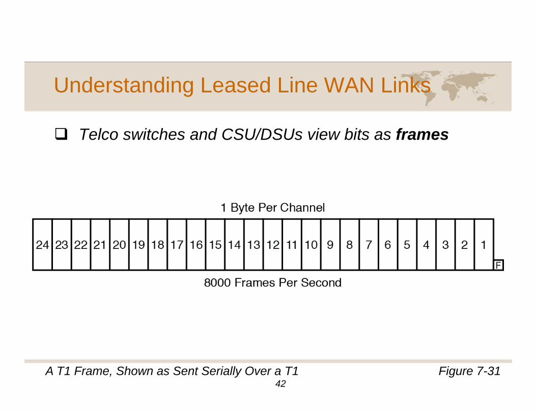
T l it h d CSU/DSU i bit fTelco switches and CSU/DSUs view bits as frames
Figure 7-31A T1 Frame, Shown as Sent Serially Over a T142
Understanding Leased Line WAN Links
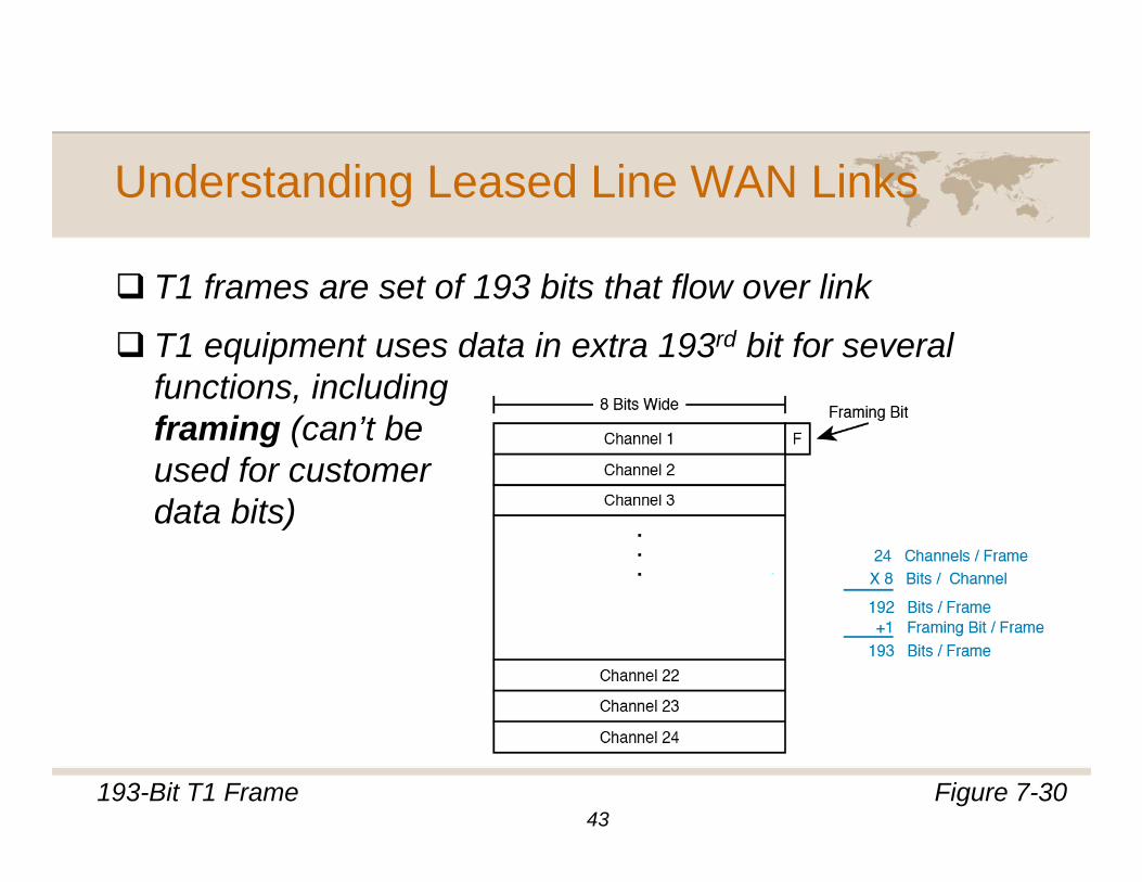
T1 f t f 193 bit th t fl li kT1 frames are set of 193 bits that flow over link
T1 equipment uses data in extra 193rd bit for several functions includingfunctions, including framing (can’t be used for customerdata bits)
Figure 7-30193-Bit T1 Frame43
Understanding Leased Line WAN Links
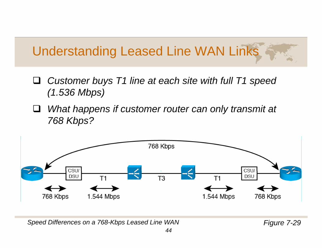
C t b T1 li t h it ith f ll T1 dCustomer buys T1 line at each site with full T1 speed (1.536 Mbps)
What happens if customer router can only transmit atWhat happens if customer router can only transmit at 768 Kbps?
Figure 7-29Speed Differences on a 768-Kbps Leased Line WAN44
Understanding Leased Line WAN Links
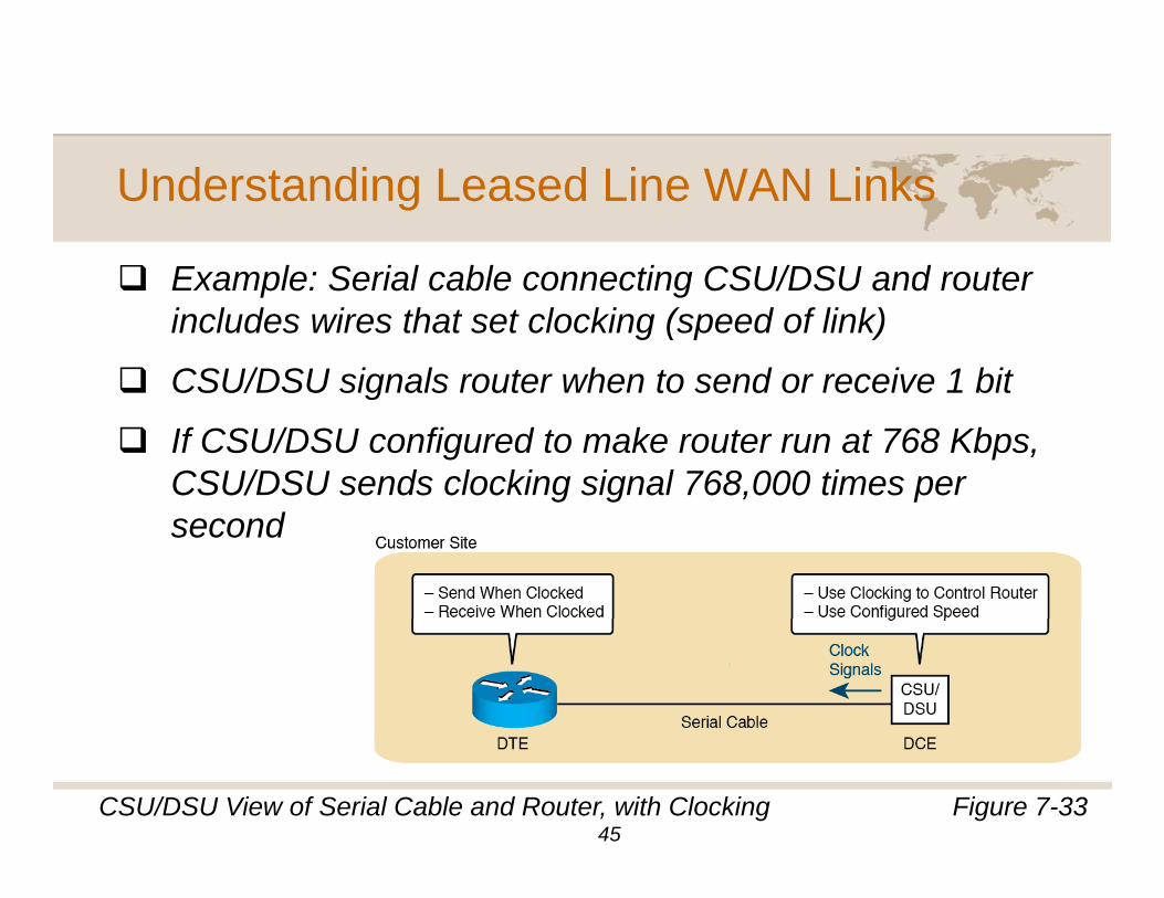
Example: Serial cable connecting CSU/DSU and routerExample: Serial cable connecting CSU/DSU and router includes wires that set clocking (speed of link)
CSU/DSU signals router when to send or receive 1 bitCSU/DSU signals router when to send or receive 1 bit
If CSU/DSU configured to make router run at 768 Kbps, CSU/DSU sends clocking signal 768,000 times per second
Figure 7-33CSU/DSU View of Serial Cable and Router, with Clocking45
Understanding Leased Line WAN Links
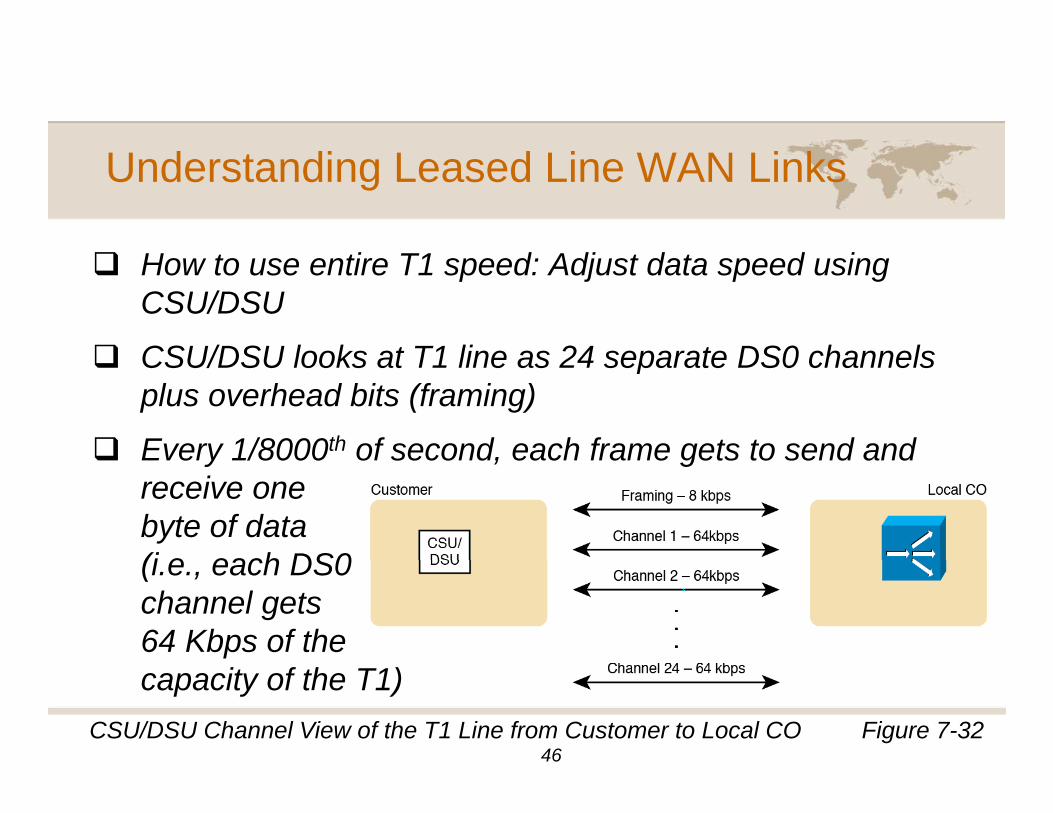
H t ti T1 d Adj t d t d iHow to use entire T1 speed: Adjust data speed using CSU/DSU
CSU/DSU looks at T1 line as 24 separate DS0 channelsCSU/DSU looks at T1 line as 24 separate DS0 channels plus overhead bits (framing)
Every 1/8000th of second, each frame gets to send andEvery 1/8000 of second, each frame gets to send and receive one byte of data (i e each DS0(i.e., each DS0 channel gets 64 Kbps of the capacity of the T1)
Figure 7-32CSU/DSU Channel View of the T1 Line from Customer to Local CO46
Understanding Leased Line WAN Links
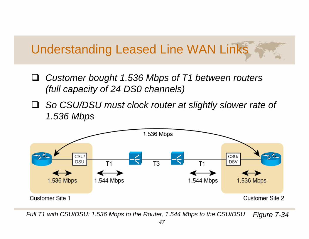
C t b ht 1 536 Mb f T1 b t tCustomer bought 1.536 Mbps of T1 between routers (full capacity of 24 DS0 channels)
So CSU/DSU must clock router at slightly slower rate ofSo CSU/DSU must clock router at slightly slower rate of 1.536 Mbps
Figure 7-34Full T1 with CSU/DSU: 1.536 Mbps to the Router, 1.544 Mbps to the CSU/DSU47
Understanding Leased Line WAN Links
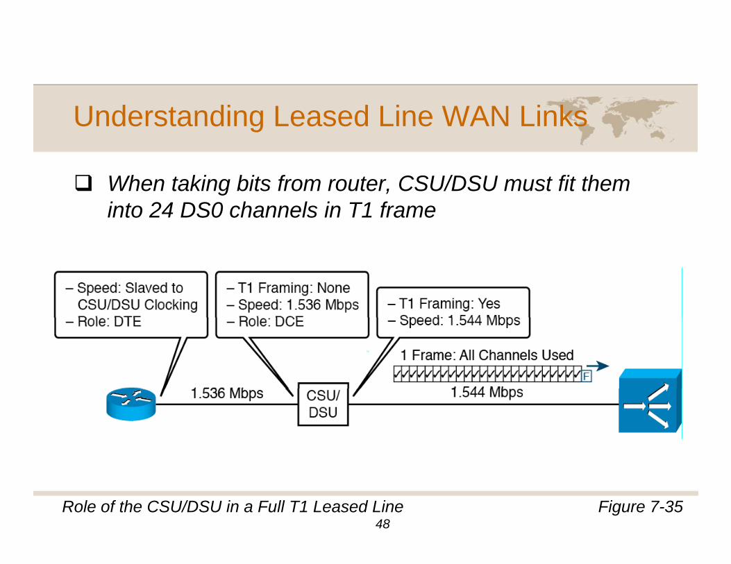
Wh t ki bit f t CSU/DSU t fit thWhen taking bits from router, CSU/DSU must fit them into 24 DS0 channels in T1 frame
Figure 7-35Role of the CSU/DSU in a Full T1 Leased Line48
Understanding Leased Line WAN Links
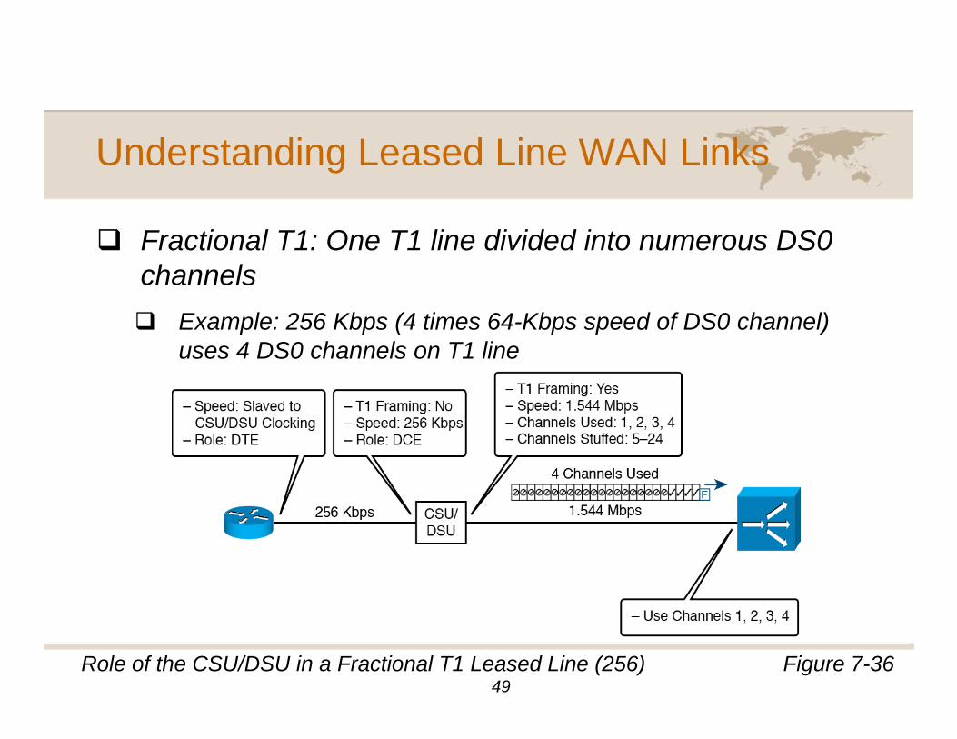
F ti l T1 O T1 li di id d i t DS0Fractional T1: One T1 line divided into numerous DS0 channels
Example: 256 Kbps (4 times 64-Kbps speed of DS0 channel)Example: 256 Kbps (4 times 64-Kbps speed of DS0 channel) uses 4 DS0 channels on T1 line
Figure 7-36Role of the CSU/DSU in a Fractional T1 Leased Line (256)49
Understanding Leased Line WAN Links
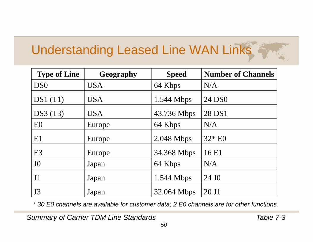
Type of Line Geography Speed Number of ChannelsType of Line Geography Speed Number of ChannelsDS0 USA 64 Kbps N/A
DS1 (T1) USA 1.544 Mbps 24 DS0
DS3 (T3) USA 43.736 Mbps 28 DS1E0 Europe 64 Kbps N/A
E1 E 2 048 Mb 32* E0E1 Europe 2.048 Mbps 32* E0
E3 Europe 34.368 Mbps 16 E1J0 Japan 64 Kbps N/Ap p
J1 Japan 1.544 Mbps 24 J0
J3 Japan 32.064 Mbps 20 J1
Table 7-3Summary of Carrier TDM Line Standards
* 30 E0 channels are available for customer data; 2 E0 channels are for other functions.
50
Understanding Leased Line WAN Links
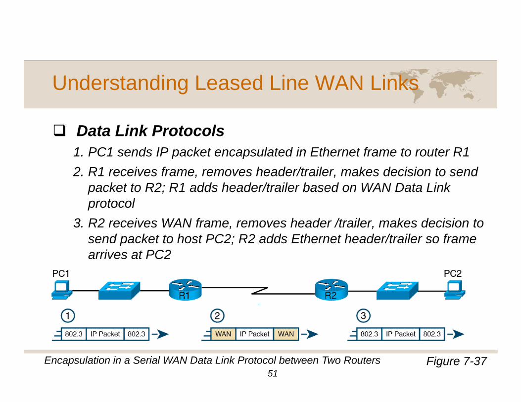
D t Li k P t lData Link Protocols1. PC1 sends IP packet encapsulated in Ethernet frame to router R12. R1 receives frame, removes header/trailer, makes decision to send2. R1 receives frame, removes header/trailer, makes decision to send
packet to R2; R1 adds header/trailer based on WAN Data Link protocol
3. R2 receives WAN frame, removes header /trailer, makes decision to3. R2 receives WAN frame, removes header /trailer, makes decision to send packet to host PC2; R2 adds Ethernet header/trailer so frame arrives at PC2
Figure 7-37Encapsulation in a Serial WAN Data Link Protocol between Two Routers51
Understanding Leased Line WAN Links
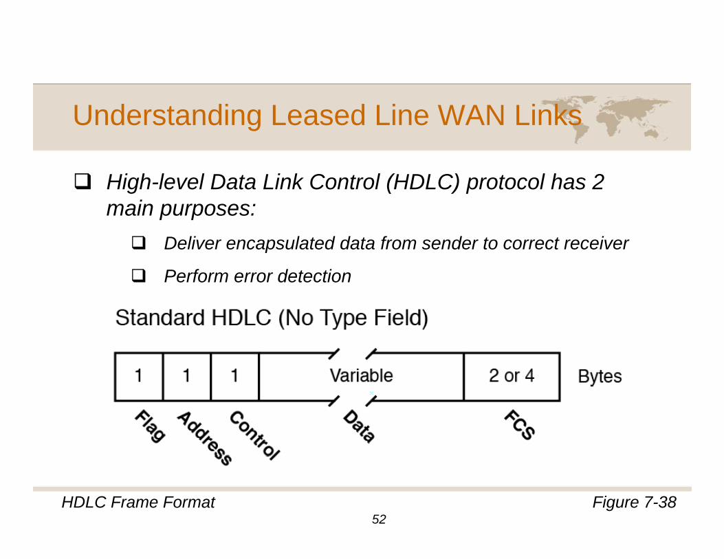
Hi h l l D t Li k C t l (HDLC) t l h 2High-level Data Link Control (HDLC) protocol has 2 main purposes:
Deliver encapsulated data from sender to correct receiverDeliver encapsulated data from sender to correct receiver
Perform error detection
Figure 7-38HDLC Frame Format52
Understanding Leased Line WAN Links
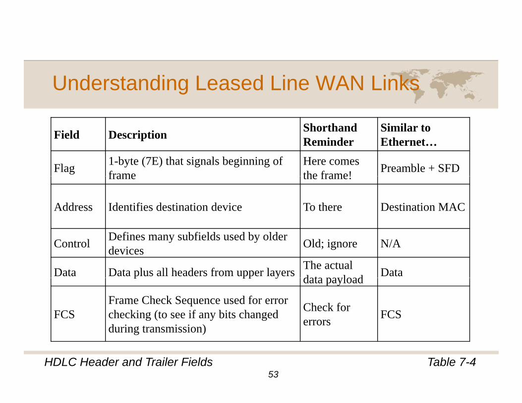
Sh th d Si il tField Description Shorthand Reminder
Similar to Ethernet…
Flag 1-byte (7E) that signals beginning of frame
Here comes the frame! Preamble + SFD frame the frame!
Address Identifies destination device To there Destination MAC
Control Defines many subfields used by older devices Old; ignore N/A
Data Data plus all headers from upper layers The actual data pa load Data p pp y data payload
FCSFrame Check Sequence used for error checking (to see if any bits changed during transmission)
Check for errors FCS
Table 7-4HDLC Header and Trailer Fields53
during transmission)
Understanding Leased Line WAN Links
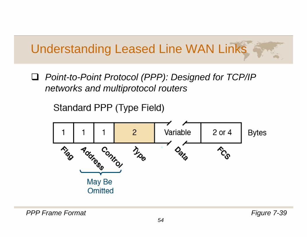
P i t t P i t P t l (PPP) D i d f TCP/IPPoint-to-Point Protocol (PPP): Designed for TCP/IP networks and multiprotocol routers
Figure 7-39PPP Frame Format54
Understanding Packet Switching and Multi-Understanding Packet Switching and MultiAccess WANs
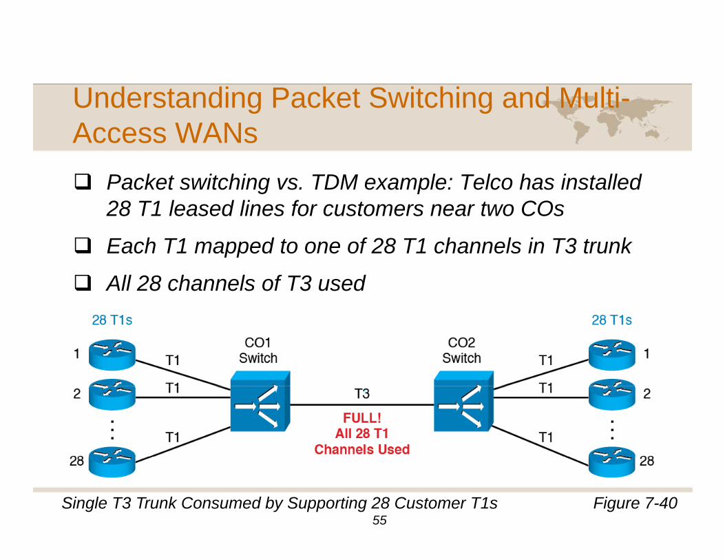
P k t it hi TDM l T l h i t ll dPacket switching vs. TDM example: Telco has installed 28 T1 leased lines for customers near two COs
Each T1 mapped to one of 28 T1 channels in T3 trunkEach T1 mapped to one of 28 T1 channels in T3 trunk
All 28 channels of T3 used
Figure 7-40Single T3 Trunk Consumed by Supporting 28 Customer T1s55
Understanding Packet Switching and Multi-Understanding Packet Switching and MultiAccess WANs
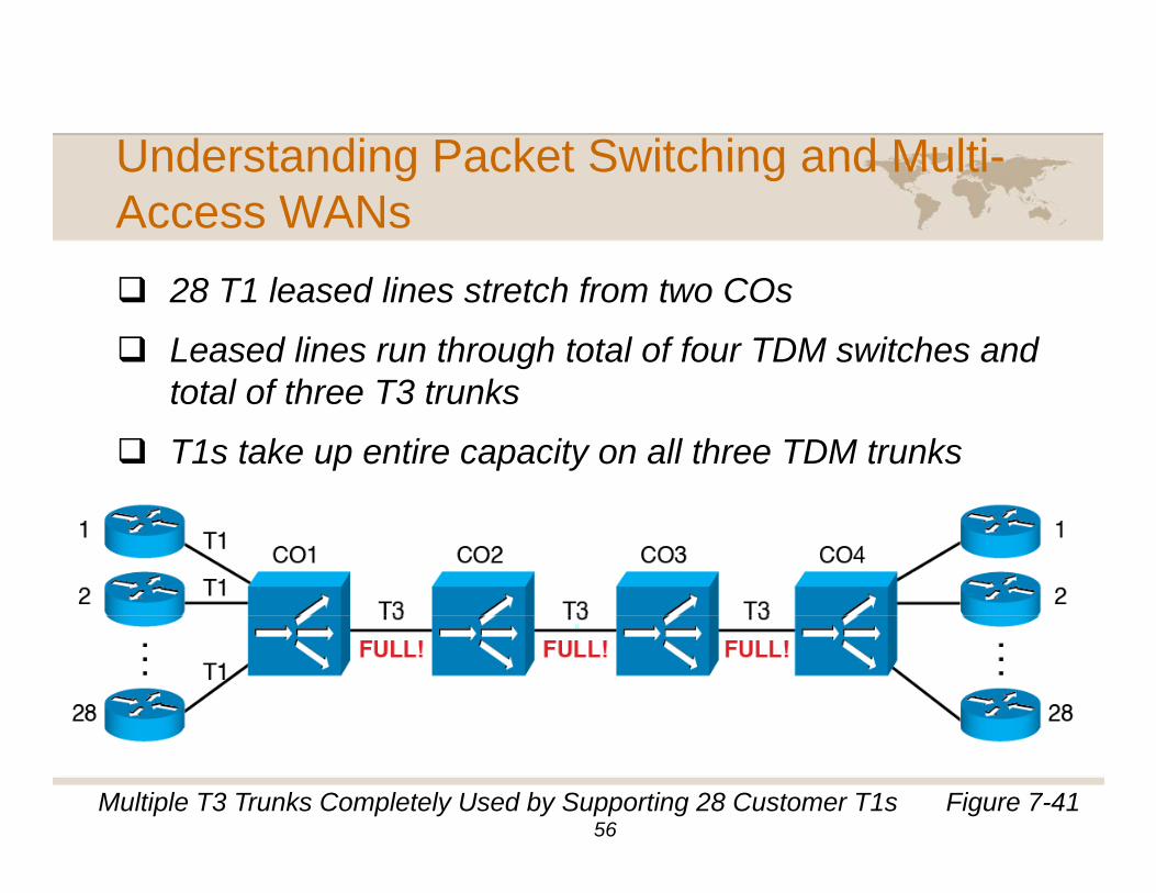
28 T1 l d li t t h f t CO28 T1 leased lines stretch from two COs
Leased lines run through total of four TDM switches and total of three T3 trunkstotal of three T3 trunks
T1s take up entire capacity on all three TDM trunks
Figure 7-41Multiple T3 Trunks Completely Used by Supporting 28 Customer T1s56
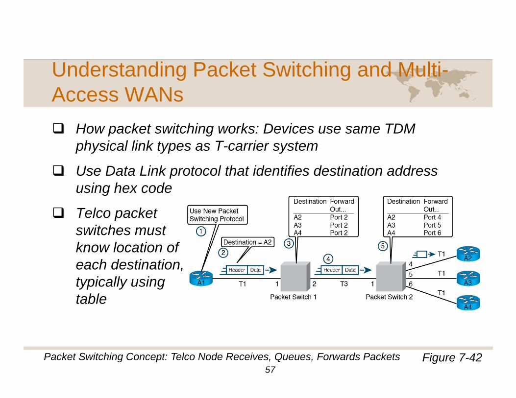
Understanding Packet Switching and Multi-Understanding Packet Switching and MultiAccess WANs
H k t it hi k D i TDMHow packet switching works: Devices use same TDM physical link types as T-carrier system
Use Data Link protocol that identifies destination addressUse Data Link protocol that identifies destination address using hex code
Telco packet switches must know location of each destination, typically using table
Figure 7-42Packet Switching Concept: Telco Node Receives, Queues, Forwards Packets57
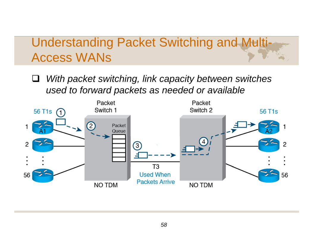
Understanding Packet Switching and Multi-Understanding Packet Switching and MultiAccess WANs
With k t it hi li k it b t it hWith packet switching, link capacity between switches used to forward packets as needed or available
58
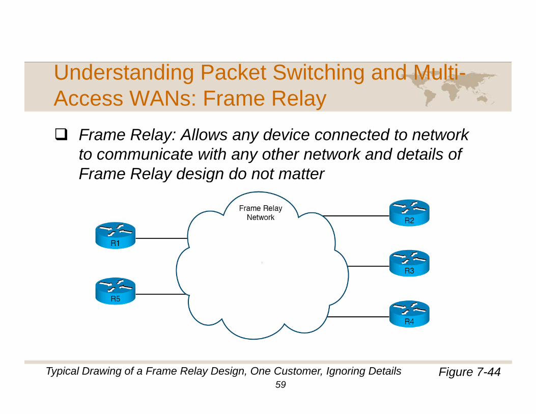
Understanding Packet Switching and Multi-Understanding Packet Switching and MultiAccess WANs: Frame Relay
F R l All d i t d t t kFrame Relay: Allows any device connected to network to communicate with any other network and details of Frame Relay design do not mattery g
Figure 7-44Typical Drawing of a Frame Relay Design, One Customer, Ignoring Details59
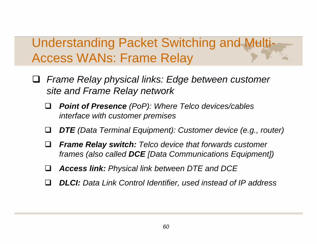
Understanding Packet Switching and Multi-Understanding Packet Switching and MultiAccess WANs: Frame Relay
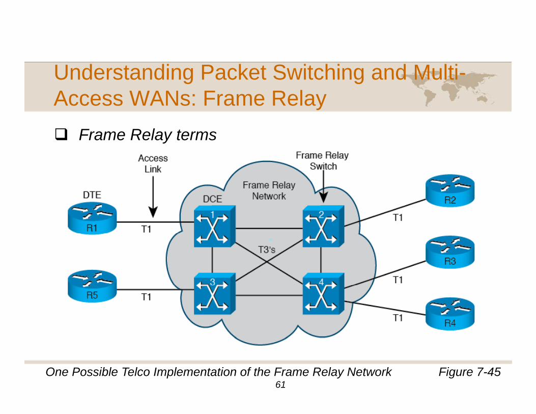
F R l h i l li k Ed b t tFrame Relay physical links: Edge between customer site and Frame Relay network
Point of Presence (PoP): Where Telco devices/cablesPoint of Presence (PoP): Where Telco devices/cables interface with customer premises
DTE (Data Terminal Equipment): Customer device (e.g., router)
Frame Relay switch: Telco device that forwards customer frames (also called DCE [Data Communications Equipment])
Access link: Physical link between DTE and DCEAccess link: Physical link between DTE and DCE
DLCI: Data Link Control Identifier, used instead of IP address
60
Understanding Packet Switching and Multi-Understanding Packet Switching and MultiAccess WANs: Frame Relay
F R l tFrame Relay terms
Figure 7-45One Possible Telco Implementation of the Frame Relay Network61
Understanding Packet Switching and Multi-Understanding Packet Switching and MultiAccess WANs: Frame Relay
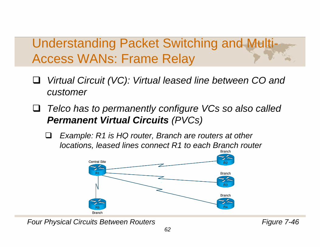
Vi t l Ci it (VC) Vi t l l d li b t CO dVirtual Circuit (VC): Virtual leased line between CO and customer
Telco has to permanently configure VCs so also calledTelco has to permanently configure VCs so also called Permanent Virtual Circuits (PVCs)
Example: R1 is HQ router, Branch are routers at other p ,locations, leased lines connect R1 to each Branch router
Figure 7-46Four Physical Circuits Between Routers62
Understanding Packet Switching and Multi-Understanding Packet Switching and MultiAccess WANs: Frame Relay
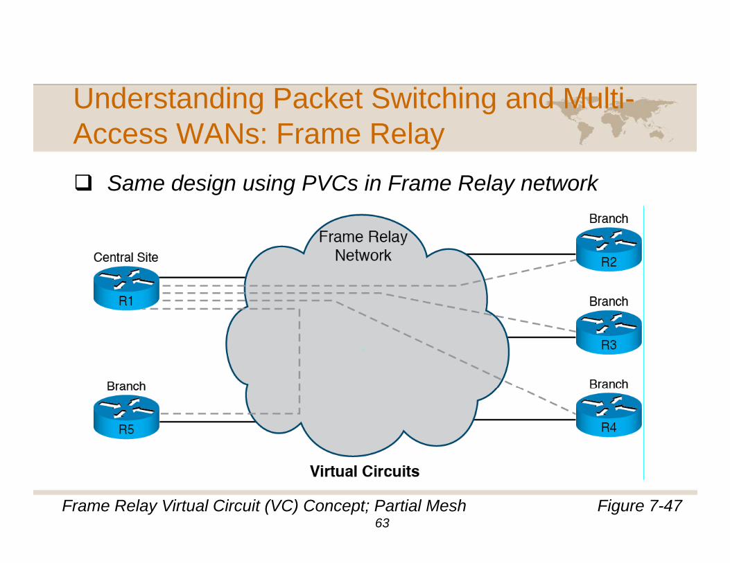
S d i i PVC i F R l t kSame design using PVCs in Frame Relay network
Figure 7-47Frame Relay Virtual Circuit (VC) Concept; Partial Mesh63
Understanding Packet Switching and Multi-Understanding Packet Switching and MultiAccess WANs: Frame Relay
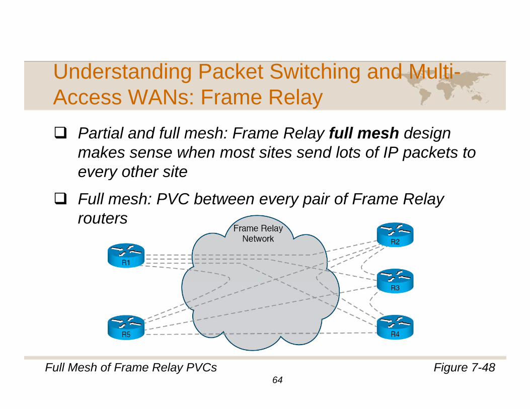
P ti l d f ll h F R l f ll h d iPartial and full mesh: Frame Relay full mesh design makes sense when most sites send lots of IP packets to every other sitey
Full mesh: PVC between every pair of Frame Relay routers
Figure 7-48Full Mesh of Frame Relay PVCs64
Understanding Packet Switching and Multi-Understanding Packet Switching and MultiAccess WANs: Frame Relay
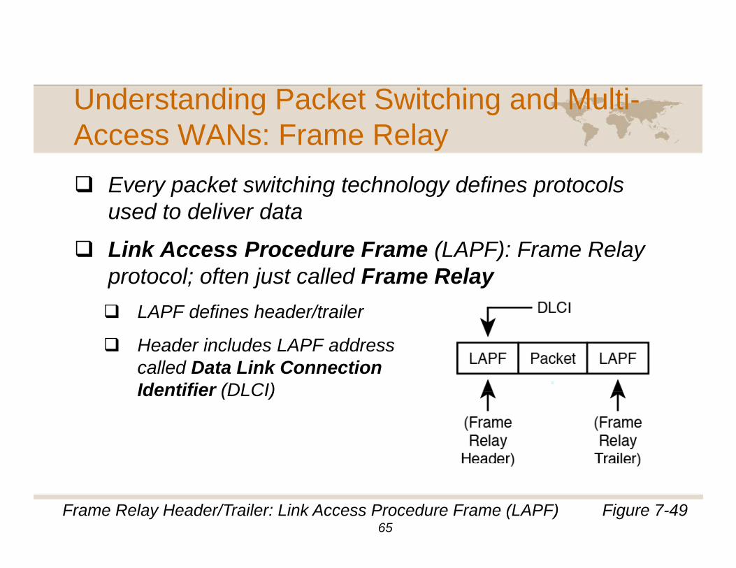
E k t it hi t h l d fi t lEvery packet switching technology defines protocols used to deliver data
Link Access Procedure Frame (LAPF): Frame RelayLink Access Procedure Frame (LAPF): Frame Relay protocol; often just called Frame Relay
LAPF defines header/trailer
Header includes LAPF address called Data Link ConnectionIdentifier (DLCI)Identifier (DLCI)
Figure 7-49Frame Relay Header/Trailer: Link Access Procedure Frame (LAPF)65
Understanding Packet Switching and Multi-Understanding Packet Switching and MultiAccess WANs: Frame Relay
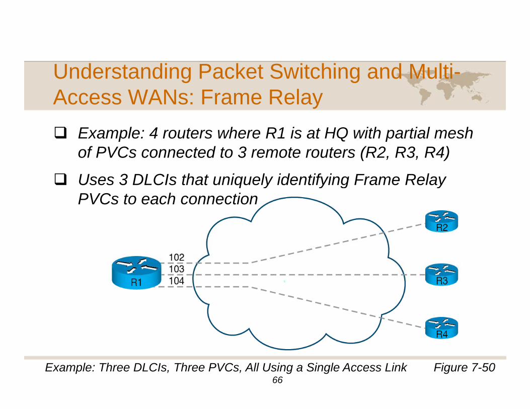
E l 4 t h R1 i t HQ ith ti l hExample: 4 routers where R1 is at HQ with partial mesh of PVCs connected to 3 remote routers (R2, R3, R4)
Uses 3 DLCIs that uniquely identifying Frame RelayUses 3 DLCIs that uniquely identifying Frame Relay PVCs to each connection
Figure 7-50Example: Three DLCIs, Three PVCs, All Using a Single Access Link 66
Understanding Packet Switching and Multi-Understanding Packet Switching and MultiAccess WANs: Frame Relay
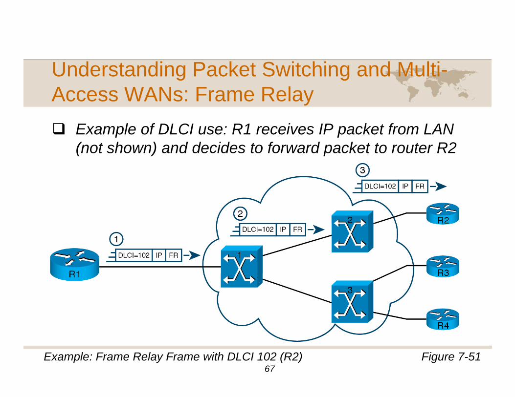
E l f DLCI R1 i IP k t f LANExample of DLCI use: R1 receives IP packet from LAN (not shown) and decides to forward packet to router R2
Figure 7-51Example: Frame Relay Frame with DLCI 102 (R2) 67
Understanding Packet Switching and Multi-Understanding Packet Switching and MultiAccess WANs
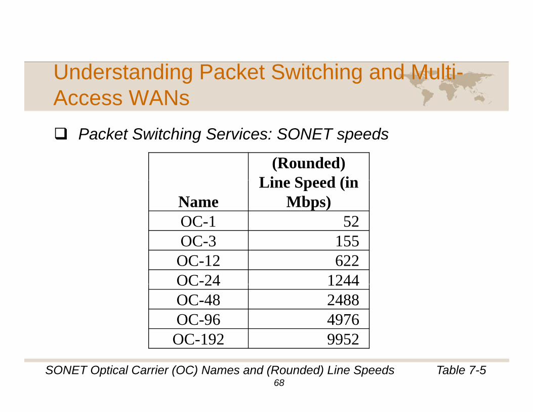
P k t S it hi S i SONET dPacket Switching Services: SONET speeds
(Rounded) Line Speed (in
NameLine Speed (in
Mbps)OC-1 52OC-3 155OC-12 622OC-24 1244OC 24 1244OC-48 2488OC-96 4976OC 192 9952
Table 7-5SONET Optical Carrier (OC) Names and (Rounded) Line Speeds
OC-192 9952
68
Understanding Packet Switching and Multi-Understanding Packet Switching and MultiAccess WANs
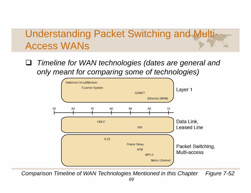
Ti li f WAN t h l i (d t l dTimeline for WAN technologies (dates are general and only meant for comparing some of technologies)
Figure 7-52Comparison Timeline of WAN Technologies Mentioned in this Chapter 69
Summary, This Chapter…Compared switched circuits as used for a typical homeCompared switched circuits as used for a typical home telephone call with two computers sending data over a similar switched circuit using modems.
Explained the basic differences between a circuit switching WAN service and a packet switching WAN service from the customer’s perspectiveservice from the customer s perspective.
Illustrated the reasons why IP routers work well at forwarding data between different types of LANs and g ypWANs.
Drew common WAN topologies.
70
Summary, This Chapter…Drew and contrasted the different customer-site cablingDrew and contrasted the different customer site cabling for a leased line WAN installed between two routers.
Listed the types of physical links in the US T-carrier yp p yhierarchy, their approximate speeds, and the specific number of slowed-speed channels that fit in the next higher-speed linehigher-speed line.
Explained how Telcos use CSU/DSUs to match a leased line speed to a physical DS1 line, using an p p y , gexample of a 768 Kbps fractional T1 leased line between two routers.
Compared and contrast the HDLC and PPP standards.
71
Summary, This Chapter…Explained the differences between packet switchingExplained the differences between packet switching and circuit switching from the Telco perspective.
Used an example network, explain how with Frame p , pRelay, a router can have one physical link connected to the WAN, but send data to many other destination routersrouters.
Listed the other WAN packet switching services, and show whether they were introduced before or after yFrame Relay.
72
Questions? Comments?
73