Embed Size (px)
Citation preview
REMOVAL1) Disconnect the battery according to thevehicle manufacturing guidelines.2) Prepare the vehicle for the timing replacementaccording to the vehicle manufacturing guide-lines.3) Bring cylinder n°1 to TDC aligning theflywheel/clutch housing markers or driveplate/automatic transmission markers (Fig. B orFig. C or Fig. D).4) Remove the cylinder head cover and lock thecamshaft using the locking ruler (4), bycentering it (Fig. E).5) Block the sprocket (5) of the injection pump(Fig. A):- engines with injection pump sprocket in two
parts: with the gauge (6) (Fig. F).- engines with injection pump sprocket in one
part: with the gauge (7) (Fig. G).6) For engines with injection pump sprocket intwo parts: loosen mounting bolts (8) of theinjection pump sprocket (fig. F).Note: Do not touch nut (9) of the pump (Fig. F).7) Remove the crankshaft pulley, loosen the nut(14) fastening the tensioner roller (2) (Fig. A),then remove the timing belt (1) as well as thetensioner roller.8) For engines with injection pump sprocket inone part: remove the idler roller (3) (Fig. A).9) Remove the stud (23) (Fig. A)
REFITTINGCaution: Clean the bearing surfaces of therollers.10) Fit and tighten the new stud (23) to thetorque of 15 N.m (Fig. A).11) Check that cylinder n°1 is at TDC.12) Engines with injection pump sprocket inone part: reassemble the new idler roller (3)and tighten its new bolt (20) to a torque of22 N.m (Fig. A).13) Reassemble the new tensioner roller (2)with its new washer (24) and new nut (14). Setthe positioning stud (10) in slot (11) of theengine block (Fig. H). Turn the adjustment dial(12) using the wrench (13) until the wrenchreaches the "8 o'clock" position (Fig. H) thentighten slightly by hand the securing nut (14)(Fig. H) on the tensioner roller.14) Loosen by a half-turn the mounting bolt(22) of the camshaft gear (15) (Fig. A).15) Pull the camshaft sprocket from the huband ensure it rotates freely around its shaft.16) Fit the new timing belt (1) on the followingelements: crankshaft gear (16), oil pump pulley(17), injection pump dented wheel (5), idlerroller (3) (according to engine), camshaft gear(15) and tensioner roller (2) (Fig. A).17) Tighten by hand the camshaft sprocketfitting bolt (22).18) Tighten the timing belt (1): turn theadjustment dial (12) on the tensioner roller (2)clockwise using the wrench (13), while holdingthe fastening nut (14) hold the roller in positionusing a hex nut wrench (Fig. H) until the mobileindex (18) is aligned with the notch (19) (Fig. I).
Then tighten the fastening nut (14) (Fig. H)at 20 N.m.19) Tighten the fastening bolt (22) of thecamshaft sprocket at 45 N.m.20) Engines with injection pump sprocket intwo parts: change the fastening bolts (8) of theinjection pump sprocket and tighten them at25 N.m (Fig. F).21) Remove the shimming ruler (4) (Fig. E) andthe gauges (6) or (7) (Fig. F and Fig. G ).22) Rotate the crankshaft by 2 turns in thedirection of rotation of the engine until the TDCfor cylinder Nr 1 is reached.23) Check the timing setting marks (Fig. B orFig. C or Fig. D) and that it is possible to lock theinjection pump sprocket using the gauges (6) or(7) (Fig. F and Fig. G ).24) Check the setting of the moving index (18)must be aligned with the notch (19) (Fig. I).25) If the marks on the tensioner roller are notaligned, proceed as follows: turn the adjustmentdial (12) counterclockwise to set the movingindex in the initial position then remove thetiming belt. Then restart the tension settingoperation at step 16).26) Refit the elements removed before in thereverse removal sequence while observing thefollowing points:Tighten the 4 crankshaft pulley bolts (21)(Fig. A) at:- For 1Z engine: 25 N.m.- For the other engines, refer to manufacturer
recommendations27) Fill the cooling circuit with the permanentfluid recommended.28) Check the circuit’s leak-tightness when theengine reaches its running temperature andsecure the level of coolant when the engine isat ambient temperature (20° C).
GB F D
NT 01004 VKMA 01015-VKMA 01016
VKMA 01015 = 1 x + 1 x + 1 x + 1 x + 1 x
= 137x23 HSN = VKM 11015 ( = M10xM8x62 = 8.4x15x1.6 = M8)
VKMA 01016 = 1 x + 1 x + 1 x + 1 x + 1 x + 1 x + 1 x
= 137x23 HSN = VKM 11015 ( = M10xM8x62 = 8.4x15x1.6 = M8)
= VKM 21012 ( = M8x40)
(4) : VAG 2065A(6) : VW 3359 / Seat U-40074(7) : VW 2064(13) : VWV 0159 / Seat U-30009A
(8) : 25 N.m(14) : 20 N.m(20) : 22 N.m(21) : 25 N.m (1Z)(22) : 45 N.m(23) : 15 N.m
NOTICES: "The SKF KITS are designed for automotive repair professionals, and must be fitted using tooling used bythese professionals. These instructions are NOT designed for private individuals. Any fitting operation not performed
by an automotive repair professional will give rise neither to guarantees, nor involve the SKF company, wavering its liability incase of non compliance with the instructions contained in this manual. This document is the exclusive property of SKF. Anyrepresentation, partial or full reproduction, is forbidden without prior written consent from SKF."
AVIS : "Les KITS SKF sont destinés aux professionnels de la réparation automobile, et doivent être montés avecles outillages que possèdent ces professionnels. En aucun cas ces instructions ne sont destinées à des particuliers.
Tout montage non effectué par un professionnel de la réparation automobile ne peut ni donner lieu à garantie, ni mettre en causela société SKF qui dégage sa responsabilité en cas de non suivi des instructions contenues dans la présente notice. Ce documentest la propriété exclusive de la société SKF. Toute représentation, reproduction partielle ou intégrale est interdite sans le consen-tement écrit de la société SKF."
HINWEIS: „Die SKF-KITS sind für Berufsmechaniker im Automobilreparaturbereich bestimmt; sie müssen mitWerkzeugen ausgestattet werden, die von diesen Mechanikern benutzt werden. Diese Anleitung ist auf keinen Fall für
Privatpersonen bestimmt. Für Montagen, die nicht von Berufsmechanikern des Automobilreparaturbereichs ausgeführt werden,kann weder die Garantie in Anspruch genommen noch die Firma SKF verantwortlich gemacht werden, die jede Haftung im Fallder Nichtbeachtung der in dieser Anleitung enthaltenen Anweisungen ablehnt. Dieses Dokument ist das ausschließliche Eigentumder Firma SKF. Jede Darstellung und Wiedergabe, ob ganz oder teilweise, ist ohne das schriftliche Einverständnis der Firma SKFuntersagt.“
GB F DNT 01004GB - INSTALLATION INSTRUCTIONSF - INSTRUCTIONS DE MONTAGED - EINBAUANLEITUNGI - ISTRUZIONI PER IL MONTAGGIOSP - INSTRUCCIONES DE MONTAJENL - MONTAGEINSTRUCTIESS - MONTERINGS INSTRUKTION
Install Confidence
SEAT / SKODA / VOLKSWAGEN
INSTALL CONFIDENCEWeb catalog : www.vsm.skf.com
Copyright SKF Group 2013Ed2 April 2013©
NT-01004-CHV12_NT-02003-CHV.qxd 08/04/13 09:03 Page1
NT 01005 VKMA 01012
Removal1) Disconnect the battery according to the vehicle
manufacturing guidelines.2) Prepare the vehicle for the timing replacement
according to the vehicle manufacturing guidelines.
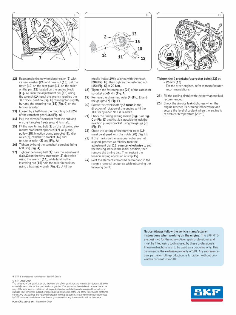
3) Bring cylinder n°1 to TDC aligning the flywheel/clutch housing markers or drive plate/automatic transmission markers (Fig. B or Fig. C or Fig. D).
4) Remove the cylinder head cover and lock the camshaft using the locking ruler (4), by center-ing it (Fig. E).
5) Block the sprocket (5) of the injection pump (Fig. A): with the gauge (7) (Fig. F).
6) Remove the crankshaft pulley, loosen the nut (15) fastening the tensioner roller (2) (Fig. A), then remove the timing belt (1) as well as the tensioner roller.
7) Remove the idler roller (3) (Fig. A).8) Remove the stud (23) (Fig. A)
RefittingCaution! Clean the bearing surfaces of the rollers.
9) Fit and tighten the new stud (23) to the torque of 15 Nm (Fig. A).
10) Check that cylinder n°1 is at TDC.11) Reassemble the new idler roller (3) and tighten
its new bolt (21) to a torque of 22 Nm (Fig. A).
REMOVAL1) Disconnect the battery according to thevehicle manufacturing guidelines.2) Prepare the vehicle for the timing replacementaccording to the vehicle manufacturing guide-lines.3) Bring cylinder n°1 to TDC aligning theflywheel/clutch housing markers or driveplate/automatic transmission markers (Fig. B orFig. C or Fig. D).4) Remove the cylinder head cover and lock thecamshaft using the locking ruler (4), bycentering it (Fig. E).5) Block the sprocket (5) of the injection pump(Fig. A):- engines with injection pump sprocket in two
parts: with the gauge (6) (Fig. F).- engines with injection pump sprocket in one
part: with the gauge (7) (Fig. G).6) For engines with injection pump sprocket intwo parts: loosen mounting bolts (8) of theinjection pump sprocket (fig. F).Note: Do not touch nut (9) of the pump (Fig. F).7) Remove the crankshaft pulley, loosen the nut(14) fastening the tensioner roller (2) (Fig. A),then remove the timing belt (1) as well as thetensioner roller.8) For engines with injection pump sprocket inone part: remove the idler roller (3) (Fig. A).9) Remove the stud (23) (Fig. A)
REFITTINGCaution: Clean the bearing surfaces of therollers.10) Fit and tighten the new stud (23) to thetorque of 15 N.m (Fig. A).11) Check that cylinder n°1 is at TDC.12) Engines with injection pump sprocket inone part: reassemble the new idler roller (3)and tighten its new bolt (20) to a torque of22 N.m (Fig. A).13) Reassemble the new tensioner roller (2)with its new washer (24) and new nut (14). Setthe positioning stud (10) in slot (11) of theengine block (Fig. H). Turn the adjustment dial(12) using the wrench (13) until the wrenchreaches the "8 o'clock" position (Fig. H) thentighten slightly by hand the securing nut (14)(Fig. H) on the tensioner roller.14) Loosen by a half-turn the mounting bolt(22) of the camshaft gear (15) (Fig. A).15) Pull the camshaft sprocket from the huband ensure it rotates freely around its shaft.16) Fit the new timing belt (1) on the followingelements: crankshaft gear (16), oil pump pulley(17), injection pump dented wheel (5), idlerroller (3) (according to engine), camshaft gear(15) and tensioner roller (2) (Fig. A).17) Tighten by hand the camshaft sprocketfitting bolt (22).18) Tighten the timing belt (1): turn theadjustment dial (12) on the tensioner roller (2)clockwise using the wrench (13), while holdingthe fastening nut (14) hold the roller in positionusing a hex nut wrench (Fig. H) until the mobileindex (18) is aligned with the notch (19) (Fig. I).
Then tighten the fastening nut (14) (Fig. H)at 20 N.m.19) Tighten the fastening bolt (22) of thecamshaft sprocket at 45 N.m.20) Engines with injection pump sprocket intwo parts: change the fastening bolts (8) of theinjection pump sprocket and tighten them at25 N.m (Fig. F).21) Remove the shimming ruler (4) (Fig. E) andthe gauges (6) or (7) (Fig. F and Fig. G ).22) Rotate the crankshaft by 2 turns in thedirection of rotation of the engine until the TDCfor cylinder Nr 1 is reached.23) Check the timing setting marks (Fig. B orFig. C or Fig. D) and that it is possible to lock theinjection pump sprocket using the gauges (6) or(7) (Fig. F and Fig. G ).24) Check the setting of the moving index (18)must be aligned with the notch (19) (Fig. I).25) If the marks on the tensioner roller are notaligned, proceed as follows: turn the adjustmentdial (12) counterclockwise to set the movingindex in the initial position then remove thetiming belt. Then restart the tension settingoperation at step 16).26) Refit the elements removed before in thereverse removal sequence while observing thefollowing points:Tighten the 4 crankshaft pulley bolts (21)(Fig. A) at:- For 1Z engine: 25 N.m.- For the other engines, refer to manufacturer
recommendations27) Fill the cooling circuit with the permanentfluid recommended.28) Check the circuit’s leak-tightness when theengine reaches its running temperature andsecure the level of coolant when the engine isat ambient temperature (20° C).
GB F D
NT 01004 VKMA 01015-VKMA 01016
VKMA 01015 = 1 x + 1 x + 1 x + 1 x + 1 x
= 137x23 HSN = VKM 11015 ( = M10xM8x62 = 8.4x15x1.6 = M8)
VKMA 01016 = 1 x + 1 x + 1 x + 1 x + 1 x + 1 x + 1 x
= 137x23 HSN = VKM 11015 ( = M10xM8x62 = 8.4x15x1.6 = M8)
= VKM 21012 ( = M8x40)
(4) : VAG 2065A(6) : VW 3359 / Seat U-40074(7) : VW 2064(13) : VWV 0159 / Seat U-30009A
(8) : 25 N.m(14) : 20 N.m(20) : 22 N.m(21) : 25 N.m (1Z)(22) : 45 N.m(23) : 15 N.m
NOTICES: "The SKF KITS are designed for automotive repair professionals, and must be fitted using tooling used bythese professionals. These instructions are NOT designed for private individuals. Any fitting operation not performed
by an automotive repair professional will give rise neither to guarantees, nor involve the SKF company, wavering its liability incase of non compliance with the instructions contained in this manual. This document is the exclusive property of SKF. Anyrepresentation, partial or full reproduction, is forbidden without prior written consent from SKF."
AVIS : "Les KITS SKF sont destinés aux professionnels de la réparation automobile, et doivent être montés avecles outillages que possèdent ces professionnels. En aucun cas ces instructions ne sont destinées à des particuliers.
Tout montage non effectué par un professionnel de la réparation automobile ne peut ni donner lieu à garantie, ni mettre en causela société SKF qui dégage sa responsabilité en cas de non suivi des instructions contenues dans la présente notice. Ce documentest la propriété exclusive de la société SKF. Toute représentation, reproduction partielle ou intégrale est interdite sans le consen-tement écrit de la société SKF."
HINWEIS: „Die SKF-KITS sind für Berufsmechaniker im Automobilreparaturbereich bestimmt; sie müssen mitWerkzeugen ausgestattet werden, die von diesen Mechanikern benutzt werden. Diese Anleitung ist auf keinen Fall für
Privatpersonen bestimmt. Für Montagen, die nicht von Berufsmechanikern des Automobilreparaturbereichs ausgeführt werden,kann weder die Garantie in Anspruch genommen noch die Firma SKF verantwortlich gemacht werden, die jede Haftung im Fallder Nichtbeachtung der in dieser Anleitung enthaltenen Anweisungen ablehnt. Dieses Dokument ist das ausschließliche Eigentumder Firma SKF. Jede Darstellung und Wiedergabe, ob ganz oder teilweise, ist ohne das schriftliche Einverständnis der Firma SKFuntersagt.“
GB F DNT 01004GB - INSTALLATION INSTRUCTIONSF - INSTRUCTIONS DE MONTAGED - EINBAUANLEITUNGI - ISTRUZIONI PER IL MONTAGGIOSP - INSTRUCCIONES DE MONTAJENL - MONTAGEINSTRUCTIESS - MONTERINGS INSTRUKTION
Install Confidence
SEAT / SKODA / VOLKSWAGEN
INSTALL CONFIDENCEWeb catalog : www.vsm.skf.com
Copyright SKF Group 2013Ed2 April 2013©
NT-01004-CHV12_NT-02003-CHV.qxd 08/04/13 09:03 Page1
B C
D
E
Skoda / Seat / Volkswagen
Install Confidence
VKMA 01012
A
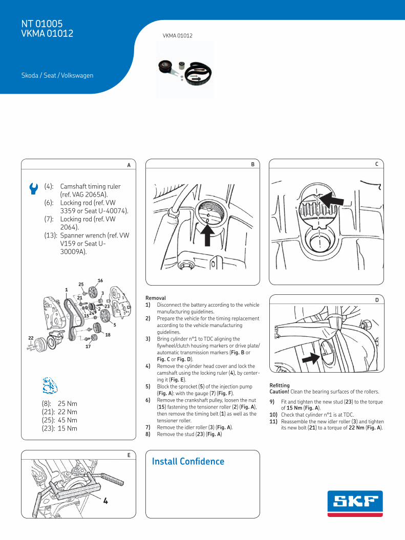
REMOVAL1) Disconnect the battery according to thevehicle manufacturing guidelines.2) Prepare the vehicle for the timing replacementaccording to the vehicle manufacturing guide-lines.3) Bring cylinder n°1 to TDC aligning the fly-wheel/clutch housing markers or driveplate/automatic transmission markers (Fig. B orFig. C or Fig. D).4) Remove the cylinder head cover and lock thecamshaft using the locking ruler (4), bycentering it (Fig. E).5) Block the sprocket (5) of the injection pump(Fig. A) with the gauge (7) (Fig. F).6) Remove the crankshaft pulley, loosen the nut(15) fastening the tensioner roller (2) (Fig. A),then remove the timing belt (1) as well as thetensioner roller.7) Remove the idler roller (3) (Fig. A).8) Remove the stud (23) (Fig. A).
REFITTINGCaution: Clean the bearing surfaces of therollers.9) Fit and tighten the new stud (23) to thetorque of 15 N.m (Fig. A).10) Check that cylinder n°1 is at TDC.11) Reassemble the new idler roller (3) andtighten its new bolt (21) to a torque of 22 N.m(Fig. A).12) Reassemble the new tensioner roller (2)with its new washer (24) and new nut (15). Setthe notch (10) on the rear plate (11) on theroller on the pin (12) located on the engineblock (Fig. G). Turn the adjustment dial (13)using the wrench (14) until the wrench reachesthe "8 o'clock" position (Fig. G) then tightenslightly by hand the securing nut (15) (Fig. G)on the tensioner roller.13) Loosen by a half-turn the mounting bolt(25) of the camshaft gear (16) (Fig. A).14) Pull the camshaft sprocket from the huband ensure it rotates freely around its shaft.15) Fit the new timing belt (1) on the followingelements: crankshaft sprocket (17), oil pumppulley (18), injection pump sprocket (5), idlerroller (3), camshaft sprocket (16) and tensionerroller (2) and (Fig. A).16) Tighten by hand the camshaft sprocketfitting bolt (25) (Fig. A).17) Tighten the distribution belt (1): turn theadjustment dial (13) on the tensioner roller (2)clockwise using the wrench (14), while holdingthe fastening nut (15) hold the roller in positionusing a hex nut wrench (Fig. G) until the mobileindex (19) is aligned with the notch (20)(Fig. H). Then tighten the fastening nut (15)(Fig. G) at 20 N.m.18) Tighten the fastening bolt (25) of the cam-shaft sprocket at 45 N.m (Fig. A).19) Remove the shimming ruler (4) (Fig. E) andthe gauge (7) (Fig. F).20) Rotate the crankshaft by 2 turns in thedirection of rotation of the engine until the TDCfor cylinder Nr 1 is reached.
21) Check the timing setting marks (Fig. B orFig. C or Fig. D) and that it is possible to lock theinjection pump sprocket using the gauge (7)(Fig. F).22) Check the setting of the moving index (19)must be aligned with the notch (20) (Fig. H).23) If the marks on the tensioner roller are notaligned, proceed as follows: turn the adjustmentdial (13) counter-clockwise to set the movingindex in the initial position, then remove thetiming belt. Then restart the tension settingoperation at step 15).24) Refit the elements removed beforehand inthe reverse removal sequence while observingthe following point:Tighten the 4 crankshaft pulley new bolts (22)(Fig. A) at: - For 1Z engine: 25 N.m.;- For the other engines, refer to manufacturer
recommendations.27) Fill the cooling circuit with the permanentfluid recommended.28) Check the circuit’s leak-tightness when theengine reaches its running temperature andsecure the level of coolant when the engine isat ambient temperature (20° C).
GB F D
NT 01005 VKMA 01012
VKMA 01012 = 1 x + 1 x + 1 x + 1 x + 1 x + 1 x + 1 x
= 63137x25 HSN = VKM 11012 ( = M10xM8x62 = 8.4x15x1.6 = M8)
= VKM 21012 ( = M8x40)
(4) : VAG 2065A(6) : VW 3359 / Seat U-40074(7) : VW 2064(13) : VWV 0159 / Seat U-30009A
(8) : 25 N.m(21) : 22 N.m(22) : 25 N.m (1Z)(23) : 15 N.m(25) : 45 N.m
NOTICES: "The SKF KITS are designed for automotive repair professionals, and must be fitted using tooling used bythese professionals. These instructions are NOT designed for private individuals. Any fitting operation not performed
by an automotive repair professional will give rise neither to guarantees, nor involve the SKF company, wavering its liability incase of non compliance with the instructions contained in this manual. This document is the exclusive property of SKF. Anyrepresentation, partial or full reproduction, is forbidden without prior written consent from SKF."
AVIS : "Les KITS SKF sont destinés aux professionnels de la réparation automobile, et doivent être montés avecles outillages que possèdent ces professionnels. En aucun cas ces instructions ne sont destinées à des particuliers.
Tout montage non effectué par un professionnel de la réparation automobile ne peut ni donner lieu à garantie, ni mettre en causela société SKF qui dégage sa responsabilité en cas de non suivi des instructions contenues dans la présente notice. Ce documentest la propriété exclusive de la société SKF. Toute représentation, reproduction partielle ou intégrale est interdite sans le consen-tement écrit de la société SKF."
HINWEIS: „Die SKF-KITS sind für Berufsmechaniker im Automobilreparaturbereich bestimmt; sie müssen mitWerkzeugen ausgestattet werden, die von diesen Mechanikern benutzt werden. Diese Anleitung ist auf keinen Fall für
Privatpersonen bestimmt. Für Montagen, die nicht von Berufsmechanikern des Automobilreparaturbereichs ausgeführt werden,kann weder die Garantie in Anspruch genommen noch die Firma SKF verantwortlich gemacht werden, die jede Haftung im Fallder Nichtbeachtung der in dieser Anleitung enthaltenen Anweisungen ablehnt. Dieses Dokument ist das ausschließliche Eigentumder Firma SKF. Jede Darstellung und Wiedergabe, ob ganz oder teilweise, ist ohne das schriftliche Einverständnis der Firma SKFuntersagt.“
GB F DNT 01005GB - INSTALLATION INSTRUCTIONSF - INSTRUCTIONS DE MONTAGED - EINBAUANLEITUNGI - ISTRUZIONI PER IL MONTAGGIOSP - INSTRUCCIONES DE MONTAJENL - MONTAGEINSTRUCTIESS - MONTERINGS INSTRUKTION
Install Confidence
AUDI / SEAT / VOLKSWAGEN
INSTALL CONFIDENCEWeb catalog : www.vsm.skf.com
Copyright SKF Group 2013Ed2 April 2013©
NT-01005-CHV12_NT-02003-CHV.qxd 08/04/13 10:01 Page1
(8): 25 Nm(21): 22 Nm(25): 45 Nm(23): 15 Nm
(4): Camshaft timing ruler (ref. VAG 2065A).
(6): Locking rod (ref. VW 3359 or Seat U-40074).
(7): Locking rod (ref. VW 2064).
(13): Spanner wrench (ref. VW V159 or Seat U-30009A).
DEPOSE1) Débrancher la batterie conformément auxinstructions constructeur.2) Préparer le véhicule pour le remplacementdu système de distribution selon les instruc-tions constructeur.3) Tourner le vilebrequin dans le sens de rota-tion du moteur jusqu'au PMH. Vérifier l'aligne-ment des repères (3) de la roue dentée d'arbreà cames (Fig. B) et (4) de la poulie de vilebre-quin (Fig. C).Nota : si nécessaire, tourner le vilebrequin d'untour supplémentaire afin d'obtenir l'alignementdes repères.4) Déposer la poulie de vilebrequin.5) Desserrer l’écrou (13) (Fig. D) du galet ten-deur et déposer la courroie de distribution.6) Déposer le galet tendeur (2).7) Déposer le goujon (15) (Fig. A).8) Démontage de la pompe à eau (VKMC01113-1/2): purger le circuit de refroidisse-ment, vérifier qu'il soit propre, et nettoyer sinécessaire, ensuite desserrer complètement lesvis (16) de la pompe à eau (12) et retirer la(Fig. A).
REPOSEAttention : Nettoyer soigneusement les surfa-ces d'appui du galet tendeur. 9) Remontage de la pompe à eau : monter lanouvelle pompe à eau (12), serrer les vis (16)au couple de 15 N.m, puis vérifier que la pou-lie de la pompe à eau tourne librement, et n’apas de points durs ou bloquant (Fig. A).10) Monter et serrer le goujon neuf (15) aucouple de 15 N.m (Fig. A).11) Vérifier l'alignement des repères de calage(3) (Fig. B).12) Reposer le galet tendeur neuf (2) : - Placer l'ergot de positionnement (5) dans l'o-rifice (6) du bloc-moteur (Fig. D). - Mettre en place la rondelle neuve (14) et l’é-crou neuf (13) (Fig. D).13) Placer la courroie neuve (1) sur le pignonde vilebrequin.14) Reposer le carter de distribution inférieuret reposer puis serrer la poulie de vilebrequin.15) Vérifier l'alignement des repères de calage(4) (Fig. C). Poursuivre l'installation de la cour-roie dans l'ordre suivant : pignon de pompe àeau, galet tendeur et roue dentée d’arbre àcames.16) Tendre la courroie de distribution (1) :- Tourner le cadran de réglage (7) (Fig. D) du
galet tendeur (2) dans le sens anti-horairejusqu’en butée puis dans le sens horairejusqu’en butée, ceci 5 fois, à l’aide de laclé (8).
- Tourner le cadran de réglage (7) du galettendeur (2) à fond dans le sens anti-horairepuis relacher le galet tendeur jusqu'à ce quel'index mobile (9) soit aligné avec l'encoche(11) (Fig. E).
17) Serrer l’écrou de fixation neuf (13) du galettendeur (2) au couple de 20 N.m (Fig. D).18) Effectuer deux tours de vilebrequin dans le
sens de rotation du moteur jusqu’au PMH.Vérifier l'alignement des repères (3) (Fig. B) et(4) (Fig. C).19) Vérifier le réglage du galet tendeur (2) :l'index mobile (9) doit être aligné avec l'encoche(11) (Fig. G).20) Si les repères du galet tendeur ne sont pasalignés, déposer la courroie de distribution.Recommencer ensuite l'opération de réglage dela tension depuis l'étape 13).21) Effectuer le remontage des éléments dépo-sés dans l’ordre inverse du démontage.22) Remplir le circuit de refroidissement avec leliquide recommandé.23) Vérifier l'étanchéité du circuit lorsque lemoteur atteint la température de fonctionne-ment et ajuster le niveau de liquide de refroi-dissement lorsque le moteur est à températureambiante (20° C).
AUSBAU1) Batterie abklemmen nach Werksvorschrift.2) Fahrzeug nach Werksvorschrift vorbereitenfür Zahnriemen Wechsel.3) Kurbelwelle im Uhrzeigersinn drehen bisOTStellung erreicht ist. Ausrichtung derEinstellmarkierungen (3) von Zahnrad derNockenwelle (Abb. B), (4) von Kurbelwellen-scheibe (Abb. C) prüfen.Anmerkung: Falls erforderlich, Kurbelwelle einezusätzliche Umdrehung bewegen, damit dieMarkierungen übereinstimmen.4) Kurbelwellescheibe ausbauen.5) Mutter (13) von Spannrolle lösen (Abb. D)und Zahnriemen ausbauen.6) Spannrolle (2) ausbauen.7) Bolzen (15) ausbauen (Abb. A).8) Wasserpumpe Entfernen (VKMC 01113-1/2). Erst Kühlerkreislauf entleeren, aufSauberkeit prüfen und erforderlichenfallsreinigen. Befestigungsschrauben (16) vollherausdrehen und Wasserpumpe (12)abnehmen (Abb. A).
EINBAUAchtung: Auflageflächen der Rollen sorgfältigreinigen.9) Einbau der Wasserpumpe. NeueWasserpumpe (12) montieren und Befestigungs-schrauben (16) mit 15 N.m anziehen. Prüfen obder Wasserpumpe weich dreht und keineharten Stellen aufweist (Abb. A). 10) Neue Bolzen (15) einbauen und mit 15 N.manziehen (Abb. A).11) Ausrichtung der Einstellmarkierungen (3)kontrollieren (Abb. B).12) Neue Spannrolle (2) einbauen: - Einstellnase (5) in Schlitz (6) von Motorblock
einrasten (Abb. D). - Die neue Scheibe (14) und neuen Mutter (13)
einbauen.13) Neuen Zahnriemen (1) auf Kurbelwellenradsetzen.14) Unteres Steuergehäuse einbauen und dannKurbelwellenscheibe einbauen und festziehen.15) Ausrichtung der Einstellmarkierungen (4)kontrollieren (Abb. C). Einbau von Zahnriemenin dieser Reihenfolge fortsetzen: Zahnrad derWasserpumpe, Spannrolle und Zahnrad derNockenwelle.16) Zahnriemen (1) spannen.- Einstellplatte (7) (Abb. D) von Spannrolle (2)
entgegen dem Uhrzeigersinn ......??????.- Schließlich Einstellplatte (7) von Spannrolle
(2) entgegen dem Uhrzeigersinn ....????.17) Den neuen Befestigungsmutter (13) desSpannrolle (2) mit einem Drehmoment von20 N.m anziehen (Abb. D).18) Mit Kurbelwelle zwei Umdrehungen imUhrzeigersinn machen bis OT-Stellung erreichtist. Ausrichtung der Einstellmarkierungen (3)
(Abb. B) und (4) (Abb. C) kontrollieren.19) Einstellung der Spannrolle (2) prüfen:bewegliche Markierung (9) muss mit Kerbe(11) ausgerichtet sein (Abb. G).20) Wenn die Markierungen der Spannrollenicht übereinstimmen, Zahnriemen ausbauen.Wiederholen Sie dann den Vorgang derSpannungseinstellung ab Schritt 13).21) Wiedereinbau der ausgebauten Elemente inumgekehrter Reihenfolge vornehmen.22) Kühlerkreislauf mit der vorgeschriebenenKühlflüssigkeit einfüllen 23) Bei Betriebstemperatur des MotorsDichtheit des Kreislaufs sorgfaltig prüfen.Kühlflüssigkeit Niveau kontrollieren beiabgekühltem Motor. (Raumtemperatur 20° C).
REMOVAL1) Disconnecting the battery according to themanufacturing guidelines.2) Prepare the vehicle for the timingreplacement according to the manufacturingguidelines.3) Turn the crankshaft in the engine rotationdirection up to TDC. Check the alignment of thetiming marks of the camshaft sprocket (3)(Fig. B) and of the crankshaft pulley (4) (Fig. C).Note: If necessary, turn the crankshaft oneextra turn to align the marks.4) Remove the crankshaft pulley.5) Slacken the tensioner roller nut (13) (Fig. D)and remove the timing belt.6) Remove the tensioner roller (2).7) Remove the stud (15) (Fig. A).8) Removing the water pump (for VKMC01113-1/2): firstly, bleed the cooling circuit,check it is clean, and clean if required; secondly,fully loosen the water pump fastening bolts(16) and remove the pump (12) (Fig. A).
REFITTINGCaution: Carefully clean the bearing surfaces ofthe tensioner roller.9) Refitting the water pump: Firstly, fit thenew water pump (12), tighten the waterpumpbolts (16) to the torque of 15 N.m, then checkthat the water pump pulley runs properly, andhas no hard or locking spots.10) Fit and tighten the new stud (15) to thetorque of 15 N.m (Fig. A).11) Check the alignment of the timing marks(3) (Fig. B).12) Fit the new tensioner roller (2): - Fit the positioning pin (5) in the hole (6) of
the engine block (Fig. D). - Fit the new washer (14) and the new nut (13)
(Fig. D).13) Fit the new belt (1) on the crankshaftsprocket.14) Refit the lower timing casing and refit thentighten the crankshaft pulley.15) Check the alignment of the timing marks(4) (Fig. C). Continue installing the belt in thefollowing order: water pump sprocket,tensioner roller and camshaft sprocket.16) Tighten the timing belt (1):- Turn the adjustment dial (7) (Fig. D) of the
tensioner roller (2) anti-clockwise andclockwise fully 5 times from maximum posi-tion to maximum position by using thewrench (8).
- Turn the adjustment dial (7) of the tensionerroller (2) fully anti-clockwise and thenslacken the tensioner until the movingpointer (9) is aligned with the notch (11)(Fig. E).
17) Tighten the new fastening nut (13) of thetensioner roller (2) to a torque of 20 N.m(Fig. D).18) Rotate the crankshaft two turns in theengine rotation direction up to TDC. Check thealignment of the marks (3) (Fig. B) and (4)(Fig. C).
19) Check the tensioner roller setting (2): themoving pointer (9) must be aligned with thenotch (11) to make sure the tension is set(Fig. G).20) If the marks of the tensioner roller are notaligned, remove the timing belt. Then restartthe adjustment operation from step 13).21) Refit the elements removed in reverseorder to removal. 22) Fill the cooling circuit with the permanentfluid recommended.23) Check the circuit’s leak-tightness when theengine reaches its running temperature andsecure the level of coolant when the engine isat ambient temperature (20° C).
GB F D
NT 01020 VKMA 01113 - VKMC 01113-1 /-2
VKMA 01113 = 1 x + 1 x + 1 x + 1 x + 1 x
VKMC 01113-1 /-2 = 1 x + 1 x + 1 x + 1 x + 1 x + 1 x
= 90138x23 HSN = VKM 11113 ( = M10xM8x62 = 8.2x18x2 = M8)
= VKPC 81408 / VKPC 81620
(8) : T10020/U-30009A
(13) : 20 N.m(15) : 15 N.m(16) : 15 N.m
NOTICES: "The SKF KITS are designed for automotive repair professionals, and must be fitted using tooling used bythese professionals. These instructions are NOT designed for private individuals. Any fitting operation not performed
by an automotive repair professional will give rise neither to guarantees, nor involve the SKF company, wavering its liability incase of non compliance with the instructions contained in this manual. This document is the exclusive property of SKF. Anyrepresentation, partial or full reproduction, is forbidden without prior written consent from SKF."
AVIS : "Les KITS SKF sont destinés aux professionnels de la réparation automobile, et doivent être montés avecles outillages que possèdent ces professionnels. En aucun cas ces instructions ne sont destinées à des particuliers.
Tout montage non effectué par un professionnel de la réparation automobile ne peut ni donner lieu à garantie, ni mettre en causela société SKF qui dégage sa responsabilité en cas de non suivi des instructions contenues dans la présente notice. Ce documentest la propriété exclusive de la société SKF. Toute représentation, reproduction partielle ou intégrale est interdite sans le consen-tement écrit de la société SKF."
HINWEIS: „Die SKF-KITS sind für Berufsmechaniker im Automobilreparaturbereich bestimmt; sie müssen mitWerkzeugen ausgestattet werden, die von diesen Mechanikern benutzt werden. Diese Anleitung ist auf keinen Fall für
Privatpersonen bestimmt. Für Montagen, die nicht von Berufsmechanikern des Automobilreparaturbereichs ausgeführt werden,kann weder die Garantie in Anspruch genommen noch die Firma SKF verantwortlich gemacht werden, die jede Haftung im Fallder Nichtbeachtung der in dieser Anleitung enthaltenen Anweisungen ablehnt. Dieses Dokument ist das ausschließliche Eigentumder Firma SKF. Jede Darstellung und Wiedergabe, ob ganz oder teilweise, ist ohne das schriftliche Einverständnis der Firma SKFuntersagt.“
GB F DNT 01020GB - INSTALLATION INSTRUCTIONSF - INSTRUCTIONS DE MONTAGED - EINBAUANLEITUNGI - ISTRUZIONI PER IL MONTAGGIOSP - INSTRUCCIONES DE MONTAJENL - MONTAGEINSTRUCTIESS - MONTERINGS INSTRUKTION
Install Confidence
AUDI / SEAT / SKODA / VOLKSWAGEN
INSTALL CONFIDENCEWeb catalog : www.vsm.skf.com
Copyright SKF Group 2012Ed2 November 2012©
® SKF is a registered trademark of the SKF Group.
© SKF Group 2014The contents of this publication are the copyright of the publisher and may not be reproduced (even extracts) unless prior written per mis sion is granted. Every care has been taken to ensure the accu-racy of the infor ma tion contained in this publication but no liability can be accepted for any loss or damage whether direct, indirect or consequential arising out of the use of the information contained herein. Any cost savings and revenue increases in this publication are based on results experienced by SKF customers and do not constitute a guarantee that any future results will be the same.
PUB 80/I1 15042 EN · November 2014
mobile index (19) is aligned with the notch (20) (Fig. H). Then tighten the fastening nut (15) (Fig. G) at 20 Nm.
18) Tighten the fastening bolt (25) of the camshaft sprocket at 45 Nm (Fig. A).
19) Remove the shimming ruler (4) (Fig. E) and the gauges (7) (Fig. F).
20) Rotate the crankshaft by 2 turns in the direction of rotation of the engine until the TDC for cylinder Nr 1 is reached.
21) Check the timing setting marks (Fig. B or Fig. C or Fig. D) and that it is possible to lock the injection pump sprocket using the gauge (7) (Fig. F).
22) Check the setting of the moving index (19) must be aligned with the notch (20) (Fig. H).
23) If the marks on the tensioner roller are not aligned, proceed as follows: turn the adjustment dial (13) counter-clockwise to set the moving index in the initial position, then remove the timing belt. Then restart the tension setting operation at step 15).
24) Refit the elements removed beforehand in the reverse removal sequence while observing the following point:
12) Reassemble the new tensioner roller (2) with its new washer (24) and new nut (15). Set the notch (10) on the rear plate (11) on the roller on the pin (12) located on the engine block (Fig. G). Turn the adjustment dial (13) using the wrench (14) until the wrench reaches the “8 o’clock” position (Fig. G) then tighten slightly by hand the securing nut (15) (Fig. G) on the tensioner roller.
13) Loosen by a half-turn the mounting bolt (25) of the camshaft gear (16) (Fig. A).
14) Pull the camshaft sprocket from the hub and ensure it rotates freely around its shaft.
15) Fit the new timing belt (1) on the following ele-ments: crankshaft sprocket (17), oil pump pulley (18), injection pump sprocket (5), idler roller (3), camshaft sprocket (16) and tensioner roller (2) and (Fig. A).
16) Tighten by hand the camshaft sprocket fitting bolt (25) (Fig. A).
17) Tighten the timing belt (1): turn the adjustment dial (13) on the tensioner roller (2) clockwise using the wrench (14), while holding the fastening nut (15) hold the roller in position using a hex nut wrench (Fig. G). Until the
Notice: Always follow the vehicle manufacturer instructions when working on the engine. The SKF KITS are designed for the automotive repair professional and must be fitted using tooling used by these professionals. These instructions are to be used as a guideline only. This document is the exclusive property of SKF. Any representa-tion, partial or full reproduction, is forbidden without prior written consent from SKF.
REMOVAL1) Disconnect the battery according to thevehicle manufacturing guidelines.2) Prepare the vehicle for the timing replacementaccording to the vehicle manufacturing guide-lines.3) Bring cylinder n°1 to TDC aligning the fly-wheel/clutch housing markers or driveplate/automatic transmission markers (Fig. B orFig. C or Fig. D).4) Remove the cylinder head cover and lock thecamshaft using the locking ruler (4), bycentering it (Fig. E).5) Block the sprocket (5) of the injection pump(Fig. A) with the gauge (7) (Fig. F).6) Remove the crankshaft pulley, loosen the nut(15) fastening the tensioner roller (2) (Fig. A),then remove the timing belt (1) as well as thetensioner roller.7) Remove the idler roller (3) (Fig. A).8) Remove the stud (23) (Fig. A).
REFITTINGCaution: Clean the bearing surfaces of therollers.9) Fit and tighten the new stud (23) to thetorque of 15 N.m (Fig. A).10) Check that cylinder n°1 is at TDC.11) Reassemble the new idler roller (3) andtighten its new bolt (21) to a torque of 22 N.m(Fig. A).12) Reassemble the new tensioner roller (2)with its new washer (24) and new nut (15). Setthe notch (10) on the rear plate (11) on theroller on the pin (12) located on the engineblock (Fig. G). Turn the adjustment dial (13)using the wrench (14) until the wrench reachesthe "8 o'clock" position (Fig. G) then tightenslightly by hand the securing nut (15) (Fig. G)on the tensioner roller.13) Loosen by a half-turn the mounting bolt(25) of the camshaft gear (16) (Fig. A).14) Pull the camshaft sprocket from the huband ensure it rotates freely around its shaft.15) Fit the new timing belt (1) on the followingelements: crankshaft sprocket (17), oil pumppulley (18), injection pump sprocket (5), idlerroller (3), camshaft sprocket (16) and tensionerroller (2) and (Fig. A).16) Tighten by hand the camshaft sprocketfitting bolt (25) (Fig. A).17) Tighten the distribution belt (1): turn theadjustment dial (13) on the tensioner roller (2)clockwise using the wrench (14), while holdingthe fastening nut (15) hold the roller in positionusing a hex nut wrench (Fig. G) until the mobileindex (19) is aligned with the notch (20)(Fig. H). Then tighten the fastening nut (15)(Fig. G) at 20 N.m.18) Tighten the fastening bolt (25) of the cam-shaft sprocket at 45 N.m (Fig. A).19) Remove the shimming ruler (4) (Fig. E) andthe gauge (7) (Fig. F).20) Rotate the crankshaft by 2 turns in thedirection of rotation of the engine until the TDCfor cylinder Nr 1 is reached.
21) Check the timing setting marks (Fig. B orFig. C or Fig. D) and that it is possible to lock theinjection pump sprocket using the gauge (7)(Fig. F).22) Check the setting of the moving index (19)must be aligned with the notch (20) (Fig. H).23) If the marks on the tensioner roller are notaligned, proceed as follows: turn the adjustmentdial (13) counter-clockwise to set the movingindex in the initial position, then remove thetiming belt. Then restart the tension settingoperation at step 15).24) Refit the elements removed beforehand inthe reverse removal sequence while observingthe following point:Tighten the 4 crankshaft pulley new bolts (22)(Fig. A) at: - For 1Z engine: 25 N.m.;- For the other engines, refer to manufacturer
recommendations.27) Fill the cooling circuit with the permanentfluid recommended.28) Check the circuit’s leak-tightness when theengine reaches its running temperature andsecure the level of coolant when the engine isat ambient temperature (20° C).
GB F D
NT 01005 VKMA 01012
VKMA 01012 = 1 x + 1 x + 1 x + 1 x + 1 x + 1 x + 1 x
= 63137x25 HSN = VKM 11012 ( = M10xM8x62 = 8.4x15x1.6 = M8)
= VKM 21012 ( = M8x40)
(4) : VAG 2065A(6) : VW 3359 / Seat U-40074(7) : VW 2064(13) : VWV 0159 / Seat U-30009A
(8) : 25 N.m(21) : 22 N.m(22) : 25 N.m (1Z)(23) : 15 N.m(25) : 45 N.m
NOTICES: "The SKF KITS are designed for automotive repair professionals, and must be fitted using tooling used bythese professionals. These instructions are NOT designed for private individuals. Any fitting operation not performed
by an automotive repair professional will give rise neither to guarantees, nor involve the SKF company, wavering its liability incase of non compliance with the instructions contained in this manual. This document is the exclusive property of SKF. Anyrepresentation, partial or full reproduction, is forbidden without prior written consent from SKF."
AVIS : "Les KITS SKF sont destinés aux professionnels de la réparation automobile, et doivent être montés avecles outillages que possèdent ces professionnels. En aucun cas ces instructions ne sont destinées à des particuliers.
Tout montage non effectué par un professionnel de la réparation automobile ne peut ni donner lieu à garantie, ni mettre en causela société SKF qui dégage sa responsabilité en cas de non suivi des instructions contenues dans la présente notice. Ce documentest la propriété exclusive de la société SKF. Toute représentation, reproduction partielle ou intégrale est interdite sans le consen-tement écrit de la société SKF."
HINWEIS: „Die SKF-KITS sind für Berufsmechaniker im Automobilreparaturbereich bestimmt; sie müssen mitWerkzeugen ausgestattet werden, die von diesen Mechanikern benutzt werden. Diese Anleitung ist auf keinen Fall für
Privatpersonen bestimmt. Für Montagen, die nicht von Berufsmechanikern des Automobilreparaturbereichs ausgeführt werden,kann weder die Garantie in Anspruch genommen noch die Firma SKF verantwortlich gemacht werden, die jede Haftung im Fallder Nichtbeachtung der in dieser Anleitung enthaltenen Anweisungen ablehnt. Dieses Dokument ist das ausschließliche Eigentumder Firma SKF. Jede Darstellung und Wiedergabe, ob ganz oder teilweise, ist ohne das schriftliche Einverständnis der Firma SKFuntersagt.“
GB F DNT 01005GB - INSTALLATION INSTRUCTIONSF - INSTRUCTIONS DE MONTAGED - EINBAUANLEITUNGI - ISTRUZIONI PER IL MONTAGGIOSP - INSTRUCCIONES DE MONTAJENL - MONTAGEINSTRUCTIESS - MONTERINGS INSTRUKTION
Install Confidence
AUDI / SEAT / VOLKSWAGEN
INSTALL CONFIDENCEWeb catalog : www.vsm.skf.com
Copyright SKF Group 2013Ed2 April 2013©
NT-01005-CHV12_NT-02003-CHV.qxd 08/04/13 10:01 Page1
REMOVAL1) Disconnect the battery according to thevehicle manufacturing guidelines.2) Prepare the vehicle for the timing replacementaccording to the vehicle manufacturing guide-lines.3) Bring cylinder n°1 to TDC aligning theflywheel/clutch housing markers or driveplate/automatic transmission markers (Fig. B orFig. C or Fig. D).4) Remove the cylinder head cover and lock thecamshaft using the locking ruler (4), bycentering it (Fig. E).5) Block the sprocket (5) of the injection pump(Fig. A):- engines with injection pump sprocket in two
parts: with the gauge (6) (Fig. F).- engines with injection pump sprocket in one
part: with the gauge (7) (Fig. G).6) For engines with injection pump sprocket intwo parts: loosen mounting bolts (8) of theinjection pump sprocket (fig. F).Note: Do not touch nut (9) of the pump (Fig. F).7) Remove the crankshaft pulley, loosen the nut(14) fastening the tensioner roller (2) (Fig. A),then remove the timing belt (1) as well as thetensioner roller.8) For engines with injection pump sprocket inone part: remove the idler roller (3) (Fig. A).9) Remove the stud (23) (Fig. A)
REFITTINGCaution: Clean the bearing surfaces of therollers.10) Fit and tighten the new stud (23) to thetorque of 15 N.m (Fig. A).11) Check that cylinder n°1 is at TDC.12) Engines with injection pump sprocket inone part: reassemble the new idler roller (3)and tighten its new bolt (20) to a torque of22 N.m (Fig. A).13) Reassemble the new tensioner roller (2)with its new washer (24) and new nut (14). Setthe positioning stud (10) in slot (11) of theengine block (Fig. H). Turn the adjustment dial(12) using the wrench (13) until the wrenchreaches the "8 o'clock" position (Fig. H) thentighten slightly by hand the securing nut (14)(Fig. H) on the tensioner roller.14) Loosen by a half-turn the mounting bolt(22) of the camshaft gear (15) (Fig. A).15) Pull the camshaft sprocket from the huband ensure it rotates freely around its shaft.16) Fit the new timing belt (1) on the followingelements: crankshaft gear (16), oil pump pulley(17), injection pump dented wheel (5), idlerroller (3) (according to engine), camshaft gear(15) and tensioner roller (2) (Fig. A).17) Tighten by hand the camshaft sprocketfitting bolt (22).18) Tighten the timing belt (1): turn theadjustment dial (12) on the tensioner roller (2)clockwise using the wrench (13), while holdingthe fastening nut (14) hold the roller in positionusing a hex nut wrench (Fig. H) until the mobileindex (18) is aligned with the notch (19) (Fig. I).
Then tighten the fastening nut (14) (Fig. H)at 20 N.m.19) Tighten the fastening bolt (22) of thecamshaft sprocket at 45 N.m.20) Engines with injection pump sprocket intwo parts: change the fastening bolts (8) of theinjection pump sprocket and tighten them at25 N.m (Fig. F).21) Remove the shimming ruler (4) (Fig. E) andthe gauges (6) or (7) (Fig. F and Fig. G ).22) Rotate the crankshaft by 2 turns in thedirection of rotation of the engine until the TDCfor cylinder Nr 1 is reached.23) Check the timing setting marks (Fig. B orFig. C or Fig. D) and that it is possible to lock theinjection pump sprocket using the gauges (6) or(7) (Fig. F and Fig. G ).24) Check the setting of the moving index (18)must be aligned with the notch (19) (Fig. I).25) If the marks on the tensioner roller are notaligned, proceed as follows: turn the adjustmentdial (12) counterclockwise to set the movingindex in the initial position then remove thetiming belt. Then restart the tension settingoperation at step 16).26) Refit the elements removed before in thereverse removal sequence while observing thefollowing points:Tighten the 4 crankshaft pulley bolts (21)(Fig. A) at:- For 1Z engine: 25 N.m.- For the other engines, refer to manufacturer
recommendations27) Fill the cooling circuit with the permanentfluid recommended.28) Check the circuit’s leak-tightness when theengine reaches its running temperature andsecure the level of coolant when the engine isat ambient temperature (20° C).
GB F D
NT 01004 VKMA 01015-VKMA 01016
VKMA 01015 = 1 x + 1 x + 1 x + 1 x + 1 x
= 137x23 HSN = VKM 11015 ( = M10xM8x62 = 8.4x15x1.6 = M8)
VKMA 01016 = 1 x + 1 x + 1 x + 1 x + 1 x + 1 x + 1 x
= 137x23 HSN = VKM 11015 ( = M10xM8x62 = 8.4x15x1.6 = M8)
= VKM 21012 ( = M8x40)
(4) : VAG 2065A(6) : VW 3359 / Seat U-40074(7) : VW 2064(13) : VWV 0159 / Seat U-30009A
(8) : 25 N.m(14) : 20 N.m(20) : 22 N.m(21) : 25 N.m (1Z)(22) : 45 N.m(23) : 15 N.m
NOTICES: "The SKF KITS are designed for automotive repair professionals, and must be fitted using tooling used bythese professionals. These instructions are NOT designed for private individuals. Any fitting operation not performed
by an automotive repair professional will give rise neither to guarantees, nor involve the SKF company, wavering its liability incase of non compliance with the instructions contained in this manual. This document is the exclusive property of SKF. Anyrepresentation, partial or full reproduction, is forbidden without prior written consent from SKF."
AVIS : "Les KITS SKF sont destinés aux professionnels de la réparation automobile, et doivent être montés avecles outillages que possèdent ces professionnels. En aucun cas ces instructions ne sont destinées à des particuliers.
Tout montage non effectué par un professionnel de la réparation automobile ne peut ni donner lieu à garantie, ni mettre en causela société SKF qui dégage sa responsabilité en cas de non suivi des instructions contenues dans la présente notice. Ce documentest la propriété exclusive de la société SKF. Toute représentation, reproduction partielle ou intégrale est interdite sans le consen-tement écrit de la société SKF."
HINWEIS: „Die SKF-KITS sind für Berufsmechaniker im Automobilreparaturbereich bestimmt; sie müssen mitWerkzeugen ausgestattet werden, die von diesen Mechanikern benutzt werden. Diese Anleitung ist auf keinen Fall für
Privatpersonen bestimmt. Für Montagen, die nicht von Berufsmechanikern des Automobilreparaturbereichs ausgeführt werden,kann weder die Garantie in Anspruch genommen noch die Firma SKF verantwortlich gemacht werden, die jede Haftung im Fallder Nichtbeachtung der in dieser Anleitung enthaltenen Anweisungen ablehnt. Dieses Dokument ist das ausschließliche Eigentumder Firma SKF. Jede Darstellung und Wiedergabe, ob ganz oder teilweise, ist ohne das schriftliche Einverständnis der Firma SKFuntersagt.“
GB F DNT 01004GB - INSTALLATION INSTRUCTIONSF - INSTRUCTIONS DE MONTAGED - EINBAUANLEITUNGI - ISTRUZIONI PER IL MONTAGGIOSP - INSTRUCCIONES DE MONTAJENL - MONTAGEINSTRUCTIESS - MONTERINGS INSTRUKTION
Install Confidence
SEAT / SKODA / VOLKSWAGEN
INSTALL CONFIDENCEWeb catalog : www.vsm.skf.com
Copyright SKF Group 2013Ed2 April 2013©
NT-01004-CHV12_NT-02003-CHV.qxd 08/04/13 09:03 Page1
HGF
Tighten the 4 crankshaft sprocket bolts (22) at: – 25 Nm (1Z) – For the other engines, refer to manufacturer
recommendations.
25) Fill the cooling circuit with the permanent fluid recommended.
26) Check the circuit’s leak-tightness when the engine reaches its running temperature and secure the level of coolant when the engine is at ambient temperature (20 °C).


![Gainesville Daily Sun. (Gainesville, Florida) 1905-11-07 [p 5].ufdcimages.uflib.ufl.edu/UF/00/02/82/98/01015/00245.pdf · 2009-05-11 · GAINESVILLE Boarding D JACKSONVILLE 475 LINE](https://img.pdfslide.us/doc/110x75/5ea3f2ffa7149177cf4913af/gainesville-daily-sun-gainesville-florida-1905-11-07-p-5-2009-05-11-gainesville.jpg)