Embed Size (px)
Citation preview

Naval Surface Warfare Center Carderock Division West Bethesda, MD 20817-5700
NSWCCD-50-TR-2009/069 December 2009
2 Hydromechanics Department Report CO
o
'{/> ^. CO c < o w
Q. O
Evaluation and Improvement of the PBD-X/MTFLOW Propulsor Analysis Software
by
o Thad J. Michael CO Q. CD
c CD E CD > o Q. E
C CD c o
-+^ CD
_3 co >
LU
O)
o s> eg
• Q O O
CO Approved for public release, distribution is unlimited.
20100115018
REPORT DOCUMENTATION PAGE Form Approved
OMB No. 0704-0188 Public reporting burden for this collection of information is estimated to average 1 hour per response, Including the time for reviewing instructions, searching existing data sources, gathering and maintaining the
<Jata needed, and completing and reviewing this collection of information. Send comments regarding this burden estimate or any other aspect of this collection of Information, Including suggestions for reducing this burden to Department of Defense, Washington Headquarters Services, Directorate for Information Operations and Reports (0704-0188), 1215 Jefferson Davis Highway, Suite 1204, Arlington, VA 22202 4302. Respondents should be aware that notwithstanding any other provision of law, no person shall be subject to any penalty for falling to comply with a collection of Information ff ft does not display a currently valid OMB control number. PLEASE DO NOT RETURN YOUR FORM TO THE ABOVE ADDRESS.
1. REPORT DATE (DD-MM-YYYY) * December 2009
2. REPORT TYPE Final
3. DATES COVERED (From - To) 05/2009 - 09/2009
4. TITLE AND SUBTITLE Evaluation and Improvement of the PBD-X/MTFLOW Propulsor Analysis Software
5a. CONTRACT NUMBER N0001409WX21237
5b. GRANT NUMBER
5c. PROGRAM ELEMENT NUMBER
6. AUTHOR(S) Thad J. Michael
5d. PROJECT NUMBER
5e. TASK NUMBER
5f. WORK UNIT NUMBER 09-1-5800-320
7. PERFORMING ORGANIZATION NAME(S) AND ADDRESS(ES) AND ADDRESS(ES)
Naval Surface Warfare Center Carderock Division 9500 Macarthur Boulevard West Bethesda, MD 20817-5700
8. PERFORMING ORGANIZATION REPORT NUMBER
NSWCCD-50-TR-2009/069
9. SPONSORING / MONITORING AGENCY NAME(S) AND ADDRESS(ES) Attn ONR 331 Chief of Naval Research Ballston Centre Tower One 800 North Quincy Street Arlington, VA 22217-5660
10. SPONSOR/MONITOR'S ACRONYM(S)
11. SPONSOR/MONITOR'S REPORT NUMBER(S)
12. DISTRIBUTION / AVAILABILITY STATEMENT " Approved for public release, distribution is unlimited.
13. SUPPLEMENTARY NOTES
14. ABSTRACT The software suite PBD-X/MTFLOW has been exercised for evaluation with both waterjet pumps and open
propellers. PBD-X is a lifting surface propeller analysis code for steady conditions. MTFLOW is an axisymmetric Euler solver used to solve the axisymmetric component of the flow field inside of a waterjet pump or in and around a propeller. The results of the PBD-X/MTFLOW calculations were compared with PBD-14/MTFLOW calculations. PBD-14 is an earlier lifting surface code which uses a different formulation for determining the effective wake when coupled with MTFLOW. It was found that PBD-X produces almost identical results to PBD-14 for open propellers when coupled with MTFLOW. For waterjet pumps, PBD-X predicts significantly less circulation. The reason for this difference is not known. However, it may be related to the different formulation used in PBD-X which improves convergence for waterjet pumps. Because past PBD-14 predictions for waterjet pumps have not been accurate, it is hoped that the predictions from PBD-X will be better. However, further development of PBD-X is required before more detailed conclusions can be made.
A postprocessor for PBD-X has been written to create the input files for BSHAPE, a blade shape design program developed for use with PBD-14. This will support the creation of a design capability using PBD-X. MTSET, the grid generation component of MTFLOW, has been modified to include additional grid spacing options. This will greatly improve the usability of MTSET and the quality of the throughflow grids while maintaining the current ease of use.
15. SUBJECT TERMS PROPULSOR, HYDRODYNAMICS
16. SECURITY CLASSIFICATION OF:
.a. REPORT UNCLASSIFIED
b. ABSTRACT UNCLASSIFIED
C. THIS PAGE UNCLASSIFIED
17. LIMITATION OF ABSTRACT
SAR
18. NUMBER OF PAGES
40
19a. NAME OF RESPONSIBLE PERSON Thad J. Michael
19b. TELEPHONE NUMBER (Include area code)
(301)227-5831
Standard Form 298 (Rev. 8-98) Prescribed by ANSI Std Z39.18

(THIS PAGE INTENTIONALLY LEFT BLANK)
NSWCCD-50-TR-2009/069

CONTENTS
ABSTRACT 1
ADMINISTRATIVE INFORMATION 1
INTRODUCTION 2
BACKGROUND 2
EVALUATION OF PBD-X 3
AXWJ-2 3
AXWJ-1 5
P4119 6
P4381 6
P4990 7
CONCLUSIONS 7
IMPROVEMENTS 7
PBD-X 7
MTSET 8
CONCLUSIONS 12
FUTURE WORK 12
ACKNOWLEDGEMENTS 12
REFERENCES 31
TABLES
1. Sample input file for grid spacing on elements, spcelements 10
2. Definition of variables in spc_elements 10
3. Sample input file for grid spacing on elements, spc_streamlines 11
4. Definition of variables in spc_streamlines 11
NSWCCD-50-TR-2009/069

FIGURES
1. AxWJ-2: MTSOL mesh with blade swept areas 13
2. AxWJ-2: Effect of number of images, spanwise cosine spacing, MKEY=17 13
3. AxWJ-2: Effect of number of images, uniform spanwise spacing, MKEY=20 14
4. AxWJ-2: Effect of MKEY, spanwise cosine spacing, number of images set to MKEY-1 14
5. AxWJ-2: Effect of MKEY, uniform spanwise spacing, number of images set to MKEY-1... 15
6. AxWJ-2: Comparison of PBD-X and PBD-14, MKEY=17, 16 images 15
7. AxWJ-2: Comparison of PBD-X and PBD-14 chordwise loading, MKEY=17, 16 images.... 16
8. AxWJ-2: Effect of wake alignment on PBD-14, cosine spanwise spacing 16
9. AxWJ-2: Two-dimensional comparison of lattices and control points 17
10. AxWJ-2: Effect of using PBD-14 lattices in PBD-X 17
11. AxWJ-2 stator: Comparison of CFX and MTFLOW inflow 18
12. AxWJ-2 stator: Convergence of MKEY for uniform and cosine spanwise spacing 18
13. AxWJ-2 stator: Comparison of PBD-X and PBD-14, MKEY=20, 19 images 19
14. AxWJ-2 stator: Comparison of PBD-X and PBD-14, MKEY=20, 19 images, cosine spacing. 19
15. AxWJ-2 stator: Two-dimensional comparison of lattices and control points 20
16. AxWJ-1: MTSOL mesh with blade swept areas 20
17. AxWJ-1: Comparison of PBD-X and PBD-14, MKEY= 17, 16 images 21
18. AxWJ-1: Comparison of spanwise loading over a range of advance coefficients, MKEY=17. 21
19. AxWJ-1: Comparison of chordwise loading at midspan, design advance coefficient 22
20. AxWJ-1 stator: Inflow velocity distribution, rotor advance coefficient of 0.80 22
21. AxWJ-1 stator: Convergence of MKEY 23
22. AxWJ-1 stator: Comparison of PBD-X and PBD-14, MK£Y=20, 19 images 23
23. P4119: Cropped tip due to lattice generation routine 24
24. P4119: Comparison of PBD-X and PBD-14 results 24
25. P4119: Effect of using PBD-14 lattice in PBD-X 25
26. P4119: Chordwise circulation distribution at midspan 25
27. P4381: MTSET grid and PBD-14 lattice 26
28. P4381: Spanwise circulation comparison over a range of advance coefficients 26
29. P4990: MTSET grid and PBD-14 lattice 27
Ti NSWCCD-50-TR-2009/069

30. P4990: Comparison of PBD-14 and PBD-X with various lattices, MKEY=17 27
31. Comparison of grids generated for AxWJ-2 with old and new MTSET 28
32. Comparison of grids generated for P4119 with old and new MTSET 29
NSWCCD-50-TR-2009/069
NOMENCLATURE
GAMMA Non-dimensional circulation
MKEY Number of spanwise points used to construct the vortex lattice
R Radius non-dimensionalized by tip radius or inlet radius
Vt Tangential velocity non-dimenionalized by free-stream velocity or mean inlet
velocity
X Axial coordinate non-dimensionalized by tip radius or inlet radius
ABBREVIATIONS
MIT Massachusetts Institute of Technology
NSWCCD Naval Surface Warfare Center, Carderock Division
ONR Office of Naval Research
RANS Reynolds-Averaged Navier-Stokes
RPM Revolutions per minute
VI NSWCCD-50-TR-2009/069

ABSTRACT
The software suite PBD-X/MTFLOWhas been exercised for evaluation
with both water jet pumps and open propellers. PBD-X is a lifting surface
propeller analysis code for steady conditions. MTFLOW is an axisymmetric
Euler solver used to solve the axisymmetric component of the flow field inside of
a waterjet pump or in and around a propeller.
The results of the PBD-X/MTFLOWcalculations were compared with
PBD-14/MTFLOWcalculations. PBD-14 is an earlier lifting surface code
which uses a different formulation for determining the effective wake when
coupled with MTFLOW. It was found that PBD-X produces almost identical
results to PBD-14 for open propellers when coupled with MTFLOW.
For waterjet pumps, PBD-X predicts significantly less circulation. The
reason for this difference is not known. However, it may be related to the
different formulation used in PBD-X which improves convergence for waterjet
pumps. Because past PBD-14 predictions for waterjet pumps have not been
accurate, it is hoped that the predictions from PBD-X will be better. However,
further development of PBD-X is required before more detailed conclusions can
be made.
A postprocessor for PBD-X has been written to create the input files for
BSHAPE, a blade shape design program developed for use with PBD-14. This
will support the creation of a design capability using PBD-X.
MTSET, the grid generation component of MTFLOW, has been modified
to include additional grid spacing options. This will greatly improve the
usability of MTSET and the quality of the throughflow grids while maintaining
the current ease of use.
ADMINISTRATIVE INFORMATION
This work was sponsored by Dr. Ki-Han Kim, Office of Naval Research (ONR), Code
331. The work was conducted by the Naval Surface Warfare Center, Carderock Division
(NSWCCD), Hydromechanics Department, Resistance and Propulsion Division (Code 5800)
under work unit number 09-1-5800-302.
NSWCCD-50-TR-2009/069

INTRODUCTION
This report describes the evaluation and improvements made to the PBD-X/MTFLOW
software for the analysis of open propellers, ducted propellers, and waterjet pumps. PBD-X is a
vortex lattice propeller analysis code in development by Professor Justin Kerwin of the
Massachusetts Institute of Technology (MIT). MTFLOW is an axisymmetric Euler solver
previously developed by Professor Mark Drela of MIT.
The first objective of this effort was to validate the software by computing open
propellers and waterjet pumps and comparing the results with the predictions of the existing
vortex lattice code, PBD-14 [1], with which the Navy has a substantial experience base. The
second objective was to make improvements to the software based on the findings of the
evaluation effort and input from users of the software.
This report is divided into two primary sections, evaluation and improvements.
BACKGROUND
PBD-14 is a vortex lattice propeller design and analysis code developed at MIT and
currently in use at the Naval Surface Warfare Center, Carderock Division (NSWCCD) [1]. For
this evaluation, PBD-14n was used, which includes modifications by NSWCCD.
PBD-X builds on the success of PBD-14, but uses a different decomposition for the
velocity field; one which is better suited to waterjet pumps [2]. For the axial and radial velocity
components, PBD-X computes total velocity at the blade surface as the sum of the
circumferential mean velocity from MTFLOW and the local velocity variation (not including the
mean) induced by the vortex lattice. The tangential total velocity component at the blade surface
is computed by convecting the upstream tangential velocity through the blade row and adding the
local velocity (including the mean) induced by the vortex lattice.
The current version of PBD-X models hubs and ducts using images, like PBD-14. A
future version will use source panels to enforce the kinematic boundary condition on the hub and
duct. PBD-X does not yet compute forces.
To compare predictions, features in PBD-14 that are not available in PBD-X were
deactivated. These include thickness, viscous drag, and wake alignment. In PBD-X the wake
follows the circumferential mean velocities from MTFLOW. With wake alignment deactivated,
PBD-14 uses a similar method.
PBD-14 can be coupled with MTFLOW for the design and analysis of propulsors [3,4],
but it can also be run in a stand-alone mode. PBD-X requires coupling with MTFLOW.
MTFLOW handles the calculation of the throughflow in the case of waterjets and ducted
2 NSWCCD-50-TR-2009/069

propellers. For open propellers, MTFLOW is also used to compute the axisymmetric flow field
although it is typically much simpler than in the other cases. MTFLOW solves the flow field on a
grid which is iteratively aligned with the flow; it follows streamtubes.
The initial grid for the MTFLOW solution is generated by the code MTSET. MTSET
uses the geometry of the hub and duct, or "elements," to create a distribution of nodes on the
surfaces. Combined with an estimated stream function, an initial grid is created and elliptically
smoothed.
EVALUATION OF PBD-X
PBD-X was evaluated by computing three open propeller and two waterjet pump
geometries and comparing the results with PBD-14 calculations. A uniform flow field was used
at the far upstream boundary. In the case of waterjet stator blades, a rotor solution from a
previous calculation was used to create the inflow to the stator blades.
The two waterjet pumps are axial flow designs funded by ONR for the purpose of
scientific measurements and calculations. The three propellers are model propellers which have
been used for scientific measurements and calculations in the past.
AXWJ-2
The ONR AxWJ-2 is a recent axial flow waterjet pump design completed at NSWCCD
and described in [5]. Computations were made at the design advance coefficient based on mean
inlet velocity, 1.19. This corresponds to the design flow coefficient of 0.85.
Rotor
The MTFLOW mesh is shown in Figure 1 with the swept 16x 17 rotor blade lattice and
21 *20 stator blade lattice. The stator was not computed by PBD-X or PBD-14. An MTFLOW
option to automatically cancel swirl was added some time ago and used for this evaluation. All
tangential velocity is cancelled at the trailing edge of the stator blade. In this way, the rotor
calculations are independent of any stator calculations.
First, several convergence studies were made to determine appropriate lattice densities
and spacings, and numbers of images for the subsequent calculations. The spanwise circulation
distribution and downstream tangential velocity distributions were compared. The effect of
changing the number of images is shown in Figures 2 and 3. It was found that the number of
images should be at least 75% of MKEY, the spanwise dimension of the vortex lattice.
NSWCCD-50-TR-2009/069

The effect of changing the spanwise lattice dimension, MKEY, is shown in Figures 4 and
5 for spanwise cosine and uniform spacings, respectively. An MKEY value of 17 was found to
be sufficient for this case with both spacings.
Figure 6 compares the predicted spanwise circulation and downstream tangential velocity
from PBD-X with predictions from PBD-14. The PBD predictions do not match. PBD-X
predicts less circulation, therefore less thrust and torque, than PBD-14. This disagreement is
most likely due to the different methods of computing the local total velocities that are used in
each of the codes. The PBD-14 method may introduce errors when the mean induced velocities
are a large fraction of the total.
Figure 7 shows the difference in the predicted chordwise loading at midspan between
PBD-X and PBD-14. It appears that the difference is a constant fraction of the loading, except
for a small difference in shape at the leading edge. It was found that the PBD-14 prediction adds
3.3% more energy to the flow than PBD-X.
To assess the importance of wake alignment for this configuration, PBD-14 was also run
with wake alignment turned on. The effect was small for cosine spanwise spacing with
MKEY=17, as shown in Figure 8. It was found that with uniform spanwise spacing, at least
MKEY=20 was required for the PBD-14 results with wake alignment to be independent of
MKEY. But the overall effect of wake alignment was small.
PBD-X generates different vortex lattices than PBD-14n, particularly for the images.
PBD-14n was modified from the original MIT version of PBD-14 to place images at the same
axial location as the vortex segment being imaged. PBD-X, like the original PBD-14, places the
images at the same axial location as the tip or root of the blade, depending on whether they are
hub images or casing images. The different lattices are overlaid in Figure 9. Fortunately, the
effect of the different lattices was found to be small. Figure 10 shows the effect of importing the
PBD-14 lattices, blade, wake, and images, into PBD-X.
Stator
To make the stator calculations independent of the rotor calculations, the circumferential
average velocity at a plane between the rotor and stator from the Reynolds-Averaged Navier-
Stokes (RANS) design calculations using CFX [5] was used as the basis for the inflow to the
stator. Figure 11 compares the CFX computed velocity distribution with the inflow used in the
PBD/MTFLOW calculations.
Convergence of the number of spanwise vortex elements was checked first. Figure 12
shows that the value MKEY=17 used for the rotor was also sufficient for the stator.
NSWCCD-50-TR-2009/069

Comparing the PBD-X and PBD-14 spanwise circulation distributions, shown in Figure
13, revealed a different shape. Loading the PBD-14 blade, wake, and image lattices into PBD-X
demonstrated that the difference was due to the PBD-X lattice, as shown in Figure 14. Figure 15
compares the PBD-X lattice with the PBD-14 lattice. The length of the wake from PBD-X
appears to be much longer than from PBD-14. This is because PBD-X uses a different method of
determining the wake length than PBD-14. Professor Kerwin notes that he has focused on
developing PBD-X for rotors at this point and not stators.
AXWJ-1
The ONR AxWJ-1 is an axial flow waterjet pump designed at NSWCCD and described
in [6]. The design was completed with PBD-14/MTFLOW. RANS was not used during the
design. Computations were made at the design advance coefficient based on mean inlet velocity,
0.61. These calculations were used to provide a second point of comparison for waterjet pumps.
Figure 16 shows the MTFLOW mesh with the blade lattices overlaid.
Rotor
Convergence studies supported the conclusions from the AxWJ-2 study. A comparison
of the spanwise circulation distribution predicted by PBD-14 and PBDX also had similar results,
as shown in Figure 17. The effect of advance coefficient, or flow coefficient, was investigated.
Figure 18 shows that the difference between the PBD-14 and PBD-X results is larger when the
rotor loading is increased at lower advance coefficients. A comparison of the chordwise
circulation distributions at midspan was similar to the AxWJ-2 results, even though the AxWJ-1
chordwise loading distribution is significantly different, as shown in Figure 19. It was found that
the PBD-14 prediction adds 6.3% more energy to the flow than PBD-X at the design conditions.
Using the PBD-14 lattice geometry in PBD-X had little effect for the rotor calculations,
whether only the blade lattice or all lattices were imported into PBD-X.
Stator
For stator calculations, the stator inflow computed with PBD-14 at a rotor advance
coefficient of 0.80, shown in Figure 20, was used for all calculations. A sensitivity study showed
that the spanwise number of lattice elements was converged at 17 with cosine spacing. However,
with uniform spacing, although the circulation was converged, the downstream tangential
velocity was not. Figure 21 shows these results.
NSWCCD-50-TR-2009/069

Comparing the PBD-14 and PBD-X predicted circulation distributions in Figure 22, they
appear almost identical. However, PBD-X predicts less downstream tangential velocity, as with
the AxWJ-2 stator.
P4119
Propeller model P4119 is a three-bladed propeller. Computations were made at the
design advance coefficient, 0.833. Geometric details can be found in [7].
Often, spanwise half-cosine spacing with the clustering at the tip is used with open
propellers. Because PBD-X only supports uniform and full cosine spacing, only those options
were evaluated.
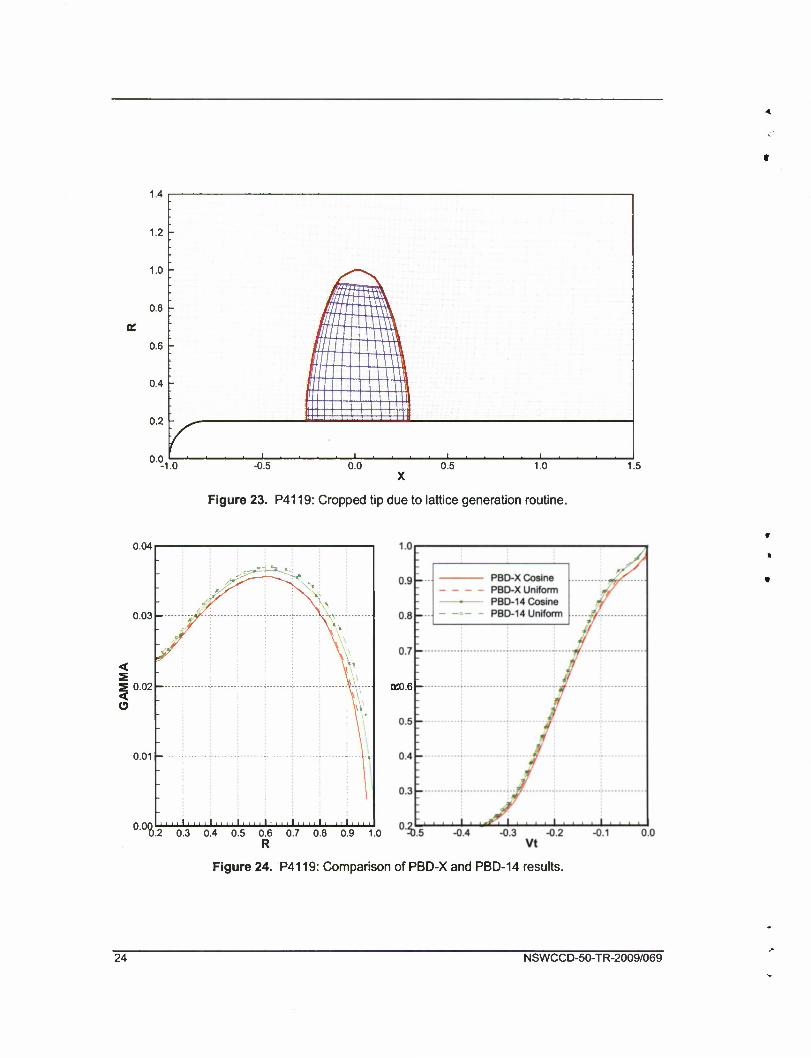
At this point, PBD-X development has focused on internal flow problems, not open
propellers. For this reason, the streamine-based lattice generation routine in PBD-X did not work
well for open propellers. Figure 23 shows how the tip of the blade was cropped by the PBD-X
lattice routine. To improve the lattice with minimal effort, automatic tip streamline detection was
added to the PBD-X lattice routine. This reduced the amount of the tip that was cropped, but
could not eliminate it.
Figure 24 compares the PBD-14 circulation prediction with PBD-X. The effect of the
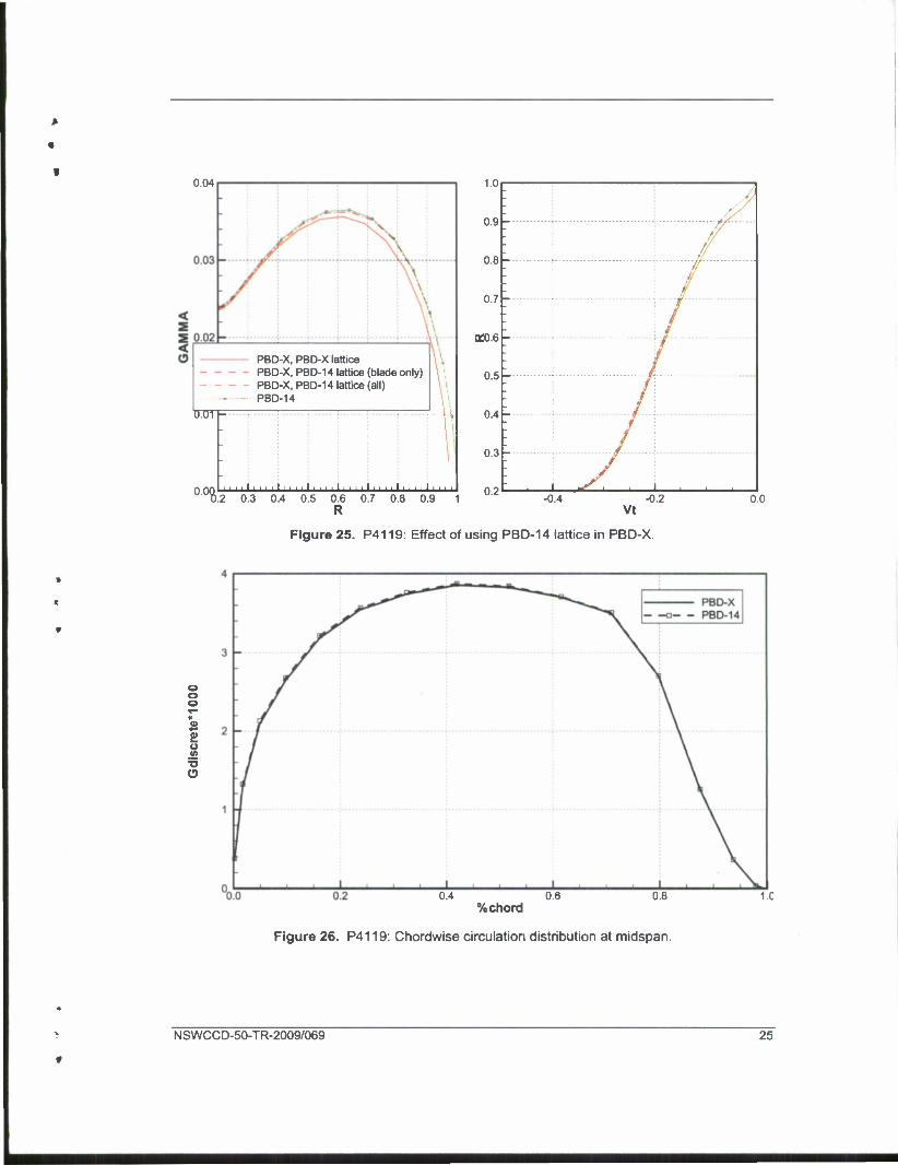
cropped tip is evident in the reduced circulation near the tip in the PBD-X solution. At this point,
the PBD-14 lattice was imported into PBD-X. Importing only the blade lattice was sufficient to
solve the cropping problem and obtain similar results. Importing all of the lattices (blade, wake,
and images) did not have a significant effect on the results. These results are shown in Figure 25.
Figure 26 shows that the chordwise circulation distribution at midspan matches when the same
lattice is used.
P4381
Propeller model P4381 is a five-bladed propeller. Computations were made at a range of
advance coefficients, including the design value, 0.889. Geometric details can be found in [8].
Figure 27 shows the MTSET grid with the PBD-14 lattice geometry.
Again, PBD-X predictions closely matched PBD-14 when the PBD-14 lattice was used.
Figure 28 shows the spanwise circulation distribution predicted by both codes over a range of
advance coefficients.
NSWCCD-50-TR-2009/069

P4990
Propeller model P4990 is a five-bladed propeller, representative of modern controllable
pitch propeller designs. Computations were made at a range of advance coefficients, including
the design value, 1.069. Geometric details can be found in [9]. Figure 29 shows the MTSET grid
with the PBD-14 lattice geometry.
Again, PBD-X predictions closely matched PBD-14 when the PBD-14 lattice was used.
Figure 30 compares the predicted spanwise circulation distribution and downstream tangential
velocity distribution from PBD-14 and PBD-X with a range of lattice sources.
CONCLUSIONS
For open propellers, when the same lattice is used, PBD-X predicts the same circulation
distribution as PBD-14. Although there is currently no force prediction from PBD-X, it can be
expected to be very close to PBD-14 based on the circulation distributions. The lack of wake
alignment and thickness will affect the results.
For waterjet pumps, PBD-X and PBD-14 results are different, even when the same lattice
is used. PBD-X is intended to be an improvement over PBD-14 for waterjet pumps, so this is
expected. However, until PBD-X is more fully developed it will be difficult to determine if there
actually is an improvement, and if so, how much of an improvement. To assess this, a method of
computing torque and including viscous drag are required so that pump curves can be plotted.
With this information, and an estimate of the effect of thickness and wake alignment from PBD-
14, the relative improvement can be assessed.
In the author's opinion, PBD-X seems to converge more rapidly and reliably than PBD-
14 for waterjet pumps. For open propellers, there is little difference.
IMPROVEMENTS
Improvements were made to both PBD-X and MTSET based on experience with the
evaluation portion of this project and anticipated needs.
PBD-X
In a planned future version, PBD-X will have a design mode. Blade geometry changes
will be handled externally by Stephen Neely's BSHAPE program [2]. The BSHAPE program
requires certain output files from PBD-14 that PBD-X does not produce, PBDOUT. IBG and
NSWCCD-50-TR-2009/069

PBDOUT. VCP. These files contain the input blade geometry and predicted velocity at the control
points.
PBD-X includes a new binary output file which contains most of the input to the code
and enough of the output to reconstruct any other required output. To create the files needed by
BSHAPE, a postprocessor was written to read the PBD-X binary file and write the files for
BSHAPE. This postprocessor is called PBDX2BSHAPE.
It was discovered that the current version of BSHAPE requires that the blade lattice be
generated with the PBD-14n lattice generation method developed by Stephen Neely. This
method created the lattice using constant parameter values of the B-spline surface. Therefore, the
PBD-14n lattice generation routine was added to PBD-X and is available by setting ILAT=2 in
the PBD-X input file. It was also necessary to add the B-spline parameter values to the PBD-X
binary file.
To use PBDX2BSHAPE, run PBD-X using ILAT=2, then run PBDX2BSHAPE. The
PBDOUT. IBG and PBDOUT. VCP files will be created. PBDX2BSHAPE will be updated as
required for compatibility with new versions of PBD-X.
MTSET
Although the original version of MTSET is relatively easy to use, the controls for
clustering grid points have proved insufficient. It is often necessary to cluster the grid points in
way of the propulsor blades. The coupling with PBD-X and PBD-14 relies on a the flow grid
being sufficiently dense to capture the velocities induced by the blades with a similar resolution
as the blade lattice.
The original version of MTSET only allows for one clustered region; and in some
instances, no clustered region is permitted. Furthermore, the clustering controls often do not
allow as much clustering as the designer would like, or the ability to reduce the number of points
in regions where they are not required.
Completely replacing MTSET with another grid generator and writing a program to
convert from that format to the MTFLOW tdat format was considered. These modern grid
generating programs have a graphical interface which allows the user to click on control points
and adjust grid clustering. Additional control points can be easily added to cluster in other areas
in contrast to the current MTSET with a command line interface and poor clustering control.
After some investigation, it was decided that while it was possible to replace MTSET, it
would make it more difficult to deal with geometry variations in an automated fashion. For this
NSWCCD-50-TR-2009/069

reason, it was decide to attempt to modify MTSET to allow more user control over the grid
spacing.
MTSET was modified to use the spacing routines written by Stephen Neely and used in
other NSWCCD software. These routines allow the user to choose from a variety of common
spacings, such as uniform and cosine, and also allow the use of a powerful parabolic spacing
specification. Furthermore, propulsor designers at NSWCCD are already familiar with the use of
these routines.
The new version of MTSET checks for the presence of two files, spc_elements, and
spcstreamlines. If found, each of these files overrides the some of the MTSET spacing
routines. The spacing on the elements, such as the duct and hub, is controlled by
spc_elements. The radial spacing, separating streamlines, is controlled by
spc_streamlines.
MTSET expects elements to be defined counterclockwise so that the top is side one, the
bottom is side two. spc_elements follows this convention. A sample spc_elements file
for a case with just a hub, P4119, is shown in Table 1 and defined in Table 2.
MTSET defines streamline spacing based on an estimated stream function. A sample
spc_streamlines file for a waterjet, AxWJ-2, is shown in Table 3 and defined in Table 4.
NSWCCD-50-TR-2009/069

Table 1. Sample input file for grid spacing on elements, spcelements.
nels 1 ispcl 10
ispc2 0
nwl 5 xl dxdwl 0.0 1.0 0.2 0.2 0.55 0.2 0.75 1.0 1.0 2.0
Table 2. Definition of variables in spcelements.
Variable Definition Recommended Values
nels Number of elements for which spacing data is to be read
0 - ignore this file >0 - number of elements
For each element (1 to nels)
ispcl, ispc2 Spacing flags for side one and side two for each element
MTSET expects elements to be defined counterclockwise so that the top is side one, the bottom is side two
Elements always have two sides, one may be a dummy
0 - uniform 1 - cosine 2 - half-cosine, close at start 3 - half-cosine, close at end 4 - double-cosine 5 - double cosine, close at start 6 - double cosine, close at end 10 - parabolic spacing
Only if ispcl = 10
nwl Number of spacing pairs Number of xl, dwl pairs to follow
xl Relative distance May be any range, will be normalized, typically 0-1
dwl Relative spacing May be any range, will be normalized, smaller for tighter spacing
Onlyifispc2 = 10
nw2 Number of spacing pairs Number of x2, dw2 pairs to follow
x2 Relative distance May be any range, will be normalized, typically 0-1
dw2 Relative spacing May be any range, will be normalized, smaller for tighter spacing
10 NSWCCD-50-TR-2009/069

Table 3. Sample input file for grid spacing on elements, spc_streamlines.
nsls 1 ispc 10 nw 3 X dxdw 0.0 0.3 0.5 1.0 1.0 0.3
Table 4. Definition of variables in spcstreamlines.
Variable Definition Recommended Values
nsls Number of streamline groups, or regions, for which spacing data is to be read
0 - ignore this file >0 - number of streamline groups
For each streamline group (1 to nsls)
ispc Spacing flags for this region 0 - uniform 1 - cosine 2 - half-cosine, close at start 3 - half-cosine, close at end 4 - double-cosine 5 - double cosine, close at start 6 - double cosine, close at end 10 - parabolic spacing
Only if ispc = 10
nw Number of spacing pairs Number of x, dw pairs to follow
X Relative distance May be any range, will be normalized, typically 0-1
dw Relative spacing May be any range, will be normalized, smaller for tighter spacing
Figures 31 and 32 compare grids generated for the AxWJ-2 and P4119, respectively, with
the original and new versions of MTSET using the same number of points. With the new version,
more grid points are clustered in way of the blades and fewer points are used far upstream and far
downstream.
NSWCCD-50-TR-2009/069 11

CONCLUSIONS
Comparative calculations show that PBD-X/MTFLOW reproduces PBD-14/MTFLOW
predictions for open propellers when the two codes are executed with similar options. This result
is encouraging. The two codes have different predictions for waterjet pumps, which is also
encouraging because the PBD-14 predictions for waterjet pumps have been unsatisfactory to date.
Improvements have been made to PBD-X and MTSET to enhance capabilities and make
the software easier to use.
FUTURE WORK
Collaborative work between Professor Kerwin and NSWCCD should continue. This is
an effective way to improve communication and will ultimately result in better software for
propulsor design.
ACKNOWLEDGEMENTS
The author would like to thank Dr. Ki-Han Kim of ONR for funding this effort.
Professor Justin Kerwin provided the current version of PBD-X and code still in development to
support this project. Scott Black and Stephen Neely provided valuable suggestions throughout
the project.
12 NSWCCD-50-TR-2009/069

Figure 1. AxWJ-2: MTSOL mesh with blade swept areas.
0.14
0.13 -
0.12 -
O 0.11 -
0.10 -
-
-
- J rf
*y I l I I I I
1.0
0.9 -
0.8 -
0.7 -
0.6 -
-
-
-
- 1=8 1=10 1=12 1=14 1=16
T? 1 - — - -
LuiLh 1_1_1_ itunhu 0.6 0.7 0.8 0.9 1.0 -1.1 -1.0 -0.9 -0.8 -0.7 -0.6 -0.5
R Vt
Figure 2. AxWJ-2: Effect of number of images, spanwise cosine spacing, MKEY=17.
NSWCCD-50-TR-2009/069 13

0.14
0.13
0.12
0.11
0.10
0.0 1 ' ' • ' ' ' ' ' ' ' • ' ' ' '
0.5 0.6 0.7 0.8 0.9 1.0 "'"1.1 -1.0 -0.9 -0.8 -0.7 -0.6 -0.5 R Vt
Figure 3. AxWJ-2: Effect of number of images, uniform spanwise spacing, MKEY=20.
Figure 4. AxWJ-2: Effect of MKEY, spanwise cosine spacing, number of images set to MKEY-1.
NKEY similar to MKEY.
14 NSWCCD-50-TR-2009/069

0.14
0.13 -
0.12 -
O 0.11 -
0.10 -
°'°%.5 0.6 0.7 0.8 0.9 1.0 "'"1.1 -1.0 -0.9 -0.8 -0.7 -0.6 -0.5 R Vt
Figure 5. AxWJ-2: Effect of MKEY, uniform spanwise spacing, number of images set to MKEY-1.
NKEY similar to MKEY.
0.14
CD 0.11 -
0.10 -
0.0$ I.5 0.6 0.7 0.8 0.9 1.0 -1.1 -1.0 -0.9 -0.8 -0.7 -0.6 -0.5
R Vt
Figure 6. AxWJ-2: Comparison of PBD-X and PBD-14, MKEY=17, 16 images.
NSWCCD-50-TR-2009/069 15

^0
— PBD-14
20
o o 15
10
o * 2! -
1 ^^^ ^*"»^ ^^*^^
u O
X
5
n
- y'
, , i 0.0 0.2 0.4 0.6
%chord 0.8 1.C
Figure 7. AxWJ-2: Comparison of PBD-X and PBD-14 chordwise loading, MKEY=17, 16 images.
Figure 8. AxWJ-2: Effect of wake alignment on PBD-14, cosine spanwise spacing.
The two cases with wake alignment are identical.
16 NSWCCD-50-TR-2009/069

Figure 9. AxWJ-2: Two-dimensional comparison of lattices and control points.
Solid lines are PBD-X; dashed lines are PBD-14.
0.14
0.13 -
< s <
0.12 -
0.11 -
0.10 -
0.(8
0.9 -
0.8 -
0.7 -
50 0.60 0.70 0.80 0.90 1.00 R;RTE
0.5
• /
: :
* i > i
I,,,
:f t
• J / PBD-X, PBD-14 lattice (all) • PBD-14
1 - I I I I s I I I -0.8 vt
-0.6
Figure 10. AxWJ-2: Effect of using PBD-14 lattices in PBD-X.
NSWCCD-50-TR-2009/069 17

1.0
0.9 -
0.8 -
0.7 -
0.6 -
: n : •
I.U
• / • CFX
LOW
0.9
0.8
<
0.7
0.6
-
/• /• /• /• / • /• /•; /• ;
/• /• /• /• /•
n <; • . /I I I I I 1 !•• ! 1.4 1.6 1.8 2.0 Vx
-1.2 -1.1 -1.0 -0.9 vt
-0.8 -0.7
Figure 11. AxWJ-2 stator: Comparison of CFX and MTFLOW inflow.
-0.065
-0.070 k
-0.075 [-
< S i0.080
O
-0.085
-0.090 h
0.8
0.7 -
0.6-
0.5 -
K0.4 -
0.3 -
0.2
0.1 -
- M=16 Cosine M=20 Cosine • M=16 Uniform
M=20 Uniform :
\
:
\
:
\ : \
: \ 1 \ :
• III 1 1 1 1 1 1 0.1 0.1 0.2 0.3 0.4 0.5 0.6 0.7 0.8 0.9 $.2 -0.1 0.0
R Vt
Figure 12. AxWJ-2 stator: Convergence of MKEY for uniform and cosine spanwise spacing.
0.2
18 NSWCCD-50-TR-2009/069

-0.065
-0.070
-0.075
2-0.080 <
-0.085
-0.090
-0.09
PBD-X Cosine PBD-X Uniform PBD-14 Cosine PBD-14 Uniform
1' ' ' ''' ' ' ''' ' ' '' • • ' ''' ' ''' • • • •''
Qffl.4 -
; ' 0.1 0.2 0.3 0.4 0.5 0.6 0.7 0.8 0.9
Figure 13. AxWJ-2 stator: Comparison of PBD-X and PBD-14, MKEY=20, 19 images.
-0.065
-0.070 -
-0.09!
0.8
0.7 -
0.6-
0.5 -
K0.4 -
0.3 -
0.2 -
0.1 -
°-i
V *
: \ \ \\ ' : \ • : - ! - -V\
l \ :. i - 44
L:^d
-0.1 0.0 vt
0.1 0.2
Figure 14. AxWJ-2 stator: Comparison of PBD-X and PBD-14, MKEY=20, 19 images, cosine spacing.
NSWCCD-50-TR-2009/069 19

1.6
1.4
1.2 -
1 -
a. 0.8 -
0.6
0.4
0.2
' •
1.2 1.4 1.6 1.8 3.2 3.4 3.6
Figure 15. AxWJ-2 stator: Two-dimensional comparison of lattices and control points.
Solid lines are PBD-X; dashed lines are PBD-14.
1.4
1.2
1
0.8
0.6
0.4
0.2
-0.5 0.5 1 X
1.5 2.5
Figure 16. AxWJ-1: MTSOL mesh with blade swept areas.
20 NSWCCD-50-TR-2009/069

0.20
0.19
0.18
0.17
0.16
0.151-
O 0.14
0.13
0.12
0.11
0.1$
Dffl.7 -
4 0.5 0.6 0.7 0.8 0.9 1.0
Figure 17. AxWJ-1: Comparison of PBD-X and PBD-14, MKEY=17, 16 images.
0.35
Figure 18. AxWJ-1: Comparison of spanwise loading over a range of advance coefficients, MKEY=17.
NSWCCD-50-TR-2009/069 21

25
20 -
15 -
2> o (A
=5 10 o
*" "• mm
PBD-14
// V 7 ^ If
If if
If II
If if
If If
x
I i i i I , 0.2 0.4 0.6
%chord 0.8
e
I
Figure 19. AxWJ-1: Comparison of chordwise loading at midspan, design advance coefficient.
1.0
0.9 -
0.8
Qffl.7
0.6
0.5
1.0
0.9
0.8
DW.7
0.6
0.5
n 41 i i i I i i i I i i i I i i i I i i i I i i i I 04L 1 1 1 I 1 1 1 I 1 1 1 I 1 1 1 I 1 1 1 0.6 0.8 1.0 1.2 1.4 1.6 1.8 3.60 -0.58 -0.56 -0.54 -0.52 -0
l.iil
Vx Vt
Figure 20. AxWJ-1 stator: Inflow velocity distribution, rotor advance coefficient of 0.80.
50
22 NSWCCD-50-TR-2009/069

-0.02
-0.025 -
-0.03 -
<;0.035 -
< O-0.04
-0.045 -
-0.05 -
-0.055
H S=
0.6
0.5
0.4
K0.3
0.2
0.1
M=17 Cosine M=20 Cosine M=17 Uniform M=20 Uniform M=23 Uniform M=26 Uniform
1 0.2 0.3 0.4 0.5 0.6 0.7 °% -0.1 0.0 vt
0.1 0.2
Figure 21. AxWJ-1 stator: Convergence of MKEY.
-0.020
-0.025 -
-0.030 -
<-0.035 -
< O-0.040
-0.045 -
-0.050
-0.05'
Qffl.3 -
1 ' ' ' ' * • ' ' ' ' ' ' ' ' ' ' ' C Il.li • Q Q j_ | , 1
0.1 0.2 0.3 0.4 0.5 0.6 0.7 $.2 -0
Figure 22. AxWJ-1 stator: Comparison of PBD-X and PBD-14, MKEY=20, 19 images.
NSWCCD-50-TR-2009/069 23
1.2
1.0
0.8
".
0.6 JCZEL
0.4 I, 11 In - .
0.2
n n r
i .... i .... i .... i ... .
-1.0 -0.5 0.0 0.5 1.0 1.5
Figure 23. P4119: Cropped tip due to lattice generation routine.
0.04
0.03
5 0.02
o
0.01
-
y
j^ ~^*~~^-
v.
- y V;
-
\
- 1
0pn*' • • '' • • • • 11 iii i • ' ' ' i' > • • 11 i i 111 i i 11 |Q ' 0.2 0.3 0.4 0.5 0.6 0.7 0.8 0
Dfl3.6 -
9 1.0
Figure 24. P4119: Comparison of PBD-X and PBD-14 results.
24 NSWCCD-50-TR-2009/069
«
f 0.04
PBD-X, PBD-X lattice PBD-X, PBD-14 lattice (blade only) PBD-X, PBD-14 lattice (all) PBD-14
inn
0 on I i iiiI i I i I I I i iiIi ii i I i i i i Iiiii I i n i I i i i11 n 2 'M).2 0.3 0.4 0.5 0.6 0.7 0.8 0.9 1
1.0
0.9 -
0.8 -
0.7 -
K0.6 -
0.5 -
0.4 -
0.3 -
:
: f/
'•
f
'-
'-
'-
'-
: i s . 1 _L. 1 . -0.4
Vt -0.2 0.0
Figure 25. P4119: Effect of using PBD-14 lattice in PBD-X.
S
•a O
0.4 0.6 %chord
0.8 1.C
Figure 26. P4119: Chordwise circulation distribution at midspan.
NSWCCD-50-TR-2009/069 25

U. 1.0
Figure 27. P4381: MTSET grid and PBD-14 lattice.
<
0.08
0.06
0.04
0.02
PBD-X PBD-14
000„l—1
Figure 28. P4381: Spanwise circulation comparison over a range of advance coefficients.
PBD-14 lattice used in PBD-X.
«
«
»
26 NSWCCD-50-TR-2009/069

t
K 1.5
Figure 29. P4990: MTSET grid and PBD-14 lattice.
»
1
0.05
0.04
0.03
<
0.02
0.01
0.0'
PBO-X, PBD-X lattice PBD-X. PBD-14 lattice (blade only) PBD-X. PBD-14 lattice (all) PBD-14
3 0.4 0.5 0.6 0.7 0.8 0.9 1.0
1.0
0.9 -
0.8-
0.7 -
0.6-
0.5-
0.4 -
0.3
- A/
-
- 4
-
1 1 i
-0.4 -0.2 R Vt
Figure 30. P4990: Comparison of PBD-14 and PBD-X with various lattices, MKEY=17.
o.o
V NSWCCD-50-TR-2009/069 27

1.0
0.5 B
0.0
0.0 0.5 1.0 1.5
*
t
t
0.0 0.5 1.0 1.5 2.0 2.5 X
1.0
n s •
nn - 2.0 2.5
Figure 31. Comparison of grids generated for AxWJ-2 with old and new MTSET.
Top: original method; bottom: new method.
28 NSWCCD-50-TR-2009/069

»
f
c
2.0
1.5 -
DC1.0 :
0.5
0.0 1.5
£1.0
-1.0 -0.5 0.0 0.5 1.0 X
1.5
Figure 32. Comparison of grids generated for P4119 with old and new MTSET.
Top: original method; bottom: new method.
f
NSWCCD-50-TR-2009/069 29

4
9
f
(THIS PAGE INTENTIONALLY LEFT BLANK)
n
* 30 NSWCCD-50-TR-2009/069

«
*
REFERENCES
1. Kerwin, J. E., et. al., "A Coupled Viscous/Potential Flow Design Method for Wake- Adapted Multi-Stage, Ducted Propulsors Using Generalized Geometry," SNAME Transactions, 1994.
2. Kerwin, J.E., Michael, T.J., and Neely, S.K., "Improved Algorithms for the Design/Analysis of Multi-Component Complex Propulsors," SNAME Propellers and Shafting Symposium, September 2006.
3. Drela, M. and Giles, M., "Conservative Streamtube Solution of Steady-State Euler Equations," Technical Report CFDL-TR-83-6, Department of Aeronautics and Astronautics, Massachusetts Institute of Technology, November 1983.
4. Renick, D.H., "An Analysis Procedure for Advanced Propulsor Design," Masters Thesis, Ocean Engineering Department, Massachusetts Institute of Technology, May 1999.
5. Michael, T.J., S.D. Schroeder, and A.J. Becnel, "Design of the ONR AxWJ-2 Axial Flow Water Jet Pump," NSWCCD Report NSWCCD-50-TR-2008/066, November 2008.
6. Wu, H., et. al., "Cavitation in the Tip Region of the Rotor Blades within a Waterjet Pump," Proceedings of FEDSM2008, Fluids Engineering Conference 2008.
7. Jessup, S.D., "An Experimental Investigation of Viscous Aspects of Propeller Blade Flow," Ph.D. Dissertation, The Catholic University of America, 1989.
8. Chesnakas, C.J., et. al., "Performance of Propeller 4381 in Crashback," NSWCCD Report NSWCCD-50-TR-2004/010, December 2004.
9. Jessup, S.D., K.D. Remmers, and W.G. Berberich, "Comparative Cavitation Performance Evaluation of a Naval Ship Propeller," Proceedings, ASME Cavitation Inception, New Orleans, Louisiana, 1993.
A NSWCCD-50-TR-2009/069 31
r

i t
(THIS PAGE INTENTIONALLY LEFT BLANK)
32 NSWCCD-50-TR-2009/069 "I
A

INITIAL DISTRIBUTION
EXTERNAL DISTRIBUTION
ORG. NAME (Copies) ONR
331 K.-H. Kim
Mass. Institute of Technology J. Kerwin
CENTER DISTRIBUTION
CODE NAME (Copies) 5060 D. Walden 5800 S. Black 5800 T. Michael 5800 S. Neely 5800 File (2)
DTIC (i:
i