Embed Size (px)
Citation preview

NSTX-U 5 Year Plan for Particle Control and Analysis for ST-FNSF
J.M. CanikS.P. Gerhardt, M.A. Jaworski, R. Maingi, E. Meier,
J.E. Menard, M. Ono, V.A Soukhanovskii, D. Stotler
For the NSTX Research TeamNSTX-U PAC-33 MeetingPPPL – B318
February 19-21, 2013
NSTX-U Supported by
Culham Sci CtrYork U
Chubu UFukui U
Hiroshima UHyogo UKyoto U
Kyushu UKyushu Tokai U
NIFSNiigata UU Tokyo
JAEAInst for Nucl Res, Kiev
Ioffe InstTRINITI
Chonbuk Natl UNFRI
KAISTPOSTECH
Seoul Natl UASIPP
CIEMATFOM Inst DIFFER
ENEA, FrascatiCEA, Cadarache
IPP, JülichIPP, Garching
ASCR, Czech Rep
Coll of Wm & MaryColumbia UCompXGeneral AtomicsFIUINLJohns Hopkins ULANLLLNLLodestarMITLehigh UNova PhotonicsOld DominionORNLPPPLPrinceton UPurdue USNLThink Tank, Inc.UC DavisUC IrvineUCLAUCSDU ColoradoU IllinoisU MarylandU RochesterU TennesseeU TulsaU WashingtonU WisconsinX Science LLC
NSTX-U NSTX-U PAC-33 – Particle Control
Motivation and overview of talk
• Particle control needs for NSTX-U: – Need to avoid density limit, radiative collapse during long-pulse shots
• Greenwald fraction fG~0.7-1.0 sufficient for non-inductive studies
– Lower density to access reduced collisionality physics• fG~0.3-0.5 desired
– Develop FNSF-relevant pumping scenarios
• Plans for Years 1-2 of NSTX-U operation: lithium and ELMs– Lithium provides deuterium control, without saturation in ~1 s in NSTX– Impurities can be flushed using ELM triggering to control radiation– Lithium granule injector is main upgrade to NSTX-U
• Plans for Years 3-4 of NSTX-U operation: cryo-pumping– Physics design of pumping system– Preliminary analysis of FNSF pumping geometry
• Goal for end of 5-year plan: stationary ne, fG~0.5, low Zeff~2-2.5
2

NSTX-U NSTX-U PAC-33 – Particle Control
Particle control in NSTX-U will be accomplished with variety of fueling and exhaust techniques
• NSTX-U will compare novel and conventional exhaust techniques – Lithium for deuterium pumping+ELM-triggering for impurity expulsion– Cryo-pumping of ELMy H-modes
• Conventional and advanced fueling techniques will be used– Supersonic gas injector (fast time response, ~1ms)– Conventional gas injectors (located at HFS, LFS, shoulder)
• Ultimately these will combined for active control over density– Will require efforts of ASC and BP TSGs– This talk will focus on exhaust (most challenging aspect in NSTX)
3

NSTX-U NSTX-U PAC-33 – Particle Control
Lithium is sufficient for controlling deuterium, with no evidence of saturation of lithium pumping in ~1 s discharges
• Plasma following strong lithium conditioning show stationary, low deuterium content
• Recycling remains reduced throughout ~1 s discharges (Boyle, PSI ‘12)– No increase near end as expected if lithium
pumping is saturated
• EAST collaboration supports use of pumping by lithium coatings for NSTX-U pulse lengths (Guo, IAEA ‘12)– L-mode, Ip=0.4 MA, PRF=1MW, LSN shots
– Fueling required to maintain constant ne compared for shots following Li deposition
– Effective e-folding time for lithium pumping is ~18 shots or 180 s
• Pumping persistence in higher-power H-mode plasmas to be assessed in future experiments
4
EAST
NSTX-U NSTX-U PAC-33 – Particle Control
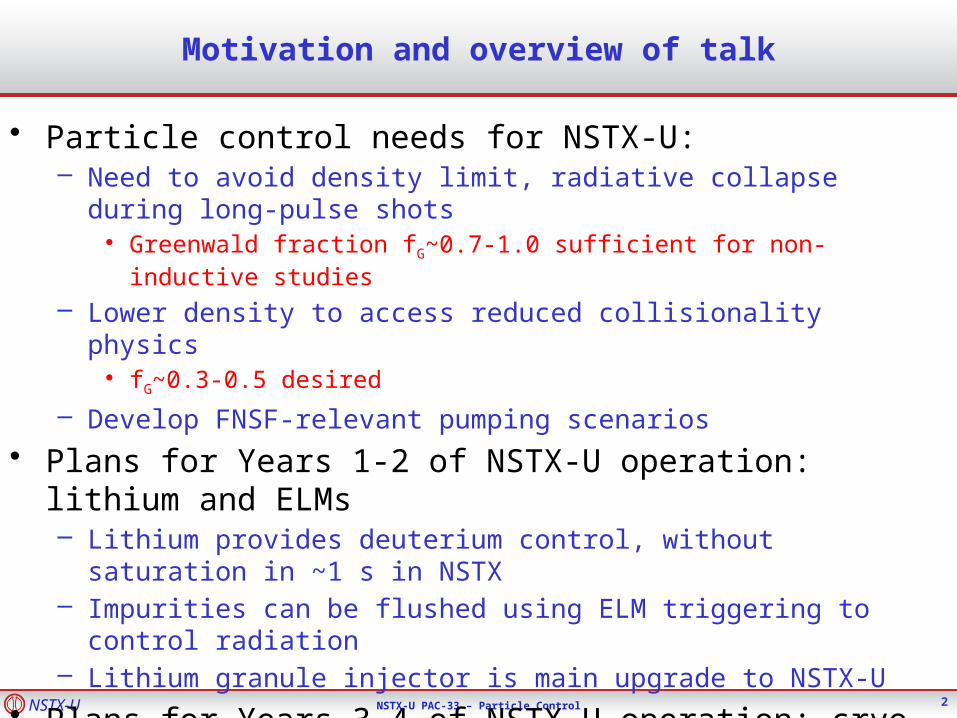
• Without impurity flushing from ELMs, Prad ramps, Zeff is high (~4)– Radiation from high-Z, Zeff from Carbon
– Fairly typical for ELM-free H-mode
• ELM-triggering with 3D fields helps to expel impurities– Prad can be kept below ~1 MW fairly easily
– Modest reduction in ne ramp, Zeff
– Large ELMs reduce rotation, trigger core MHD modes at high frequency
• Initial NSTX-U operation will use lithium+ELMs for particle control– Can also combine with other methods for reducing
impurities (e.g., divertor gas puff, snowflake)– Likely limited to high fG
– Should allow pulse lengths past ~1.5 s, how far past is TBD
ELM-free lithium operation exhibits impurity accumulation
5
NSTX-U NSTX-U PAC-33 – Particle Control
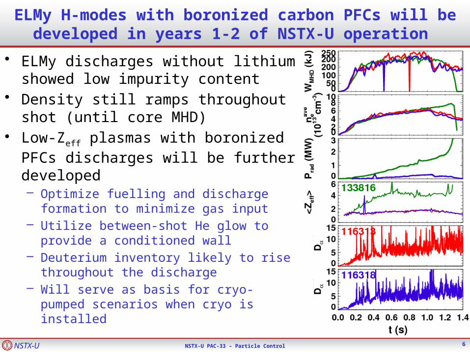
ELMy H-modes with boronized carbon PFCs will be developed in years 1-2 of NSTX-U operation
6
• ELMy discharges without lithium showed low impurity content
• Density still ramps throughout shot (until core MHD)
• Low-Zeff plasmas with boronized PFCs discharges will be further developed– Optimize fuelling and discharge formation
to minimize gas input– Utilize between-shot He glow to provide a
conditioned wall– Deuterium inventory likely to rise
throughout the discharge– Will serve as basis for cryo-pumped
scenarios when cryo is installed

NSTX-U NSTX-U PAC-33 – Particle Control
Years 1-2 of NSTX-U operation will test lithium for deuterium control, with ELMs to mitigate impurity accumulation
7
• ELM-triggering with 3D fields helps to expel impurities (Canik NF ‘12)– Prad can be kept below ~1 MW fairly easily
– Modest reduction in ne ramp, Zeff
• Initial NSTX-U operation will test the use of lithium+ELMs for particle control– Likely limited to high fG(~0.8-1.0) and high Zeff
(3-3.5)– Should allow pulse lengths past ~1.5 s, how
far past is TBD
• FY15 goals will be to re-establish, and extend ELM-paced scenarios– Combine with other methods for reducing
impurities (e.g., divertor gas puff, snowflake)– Improve ELM triggering (vertical jogs, Li
optimization to avoid ELM suppression)
NSTX-U NSTX-U PAC-33 – Particle Control
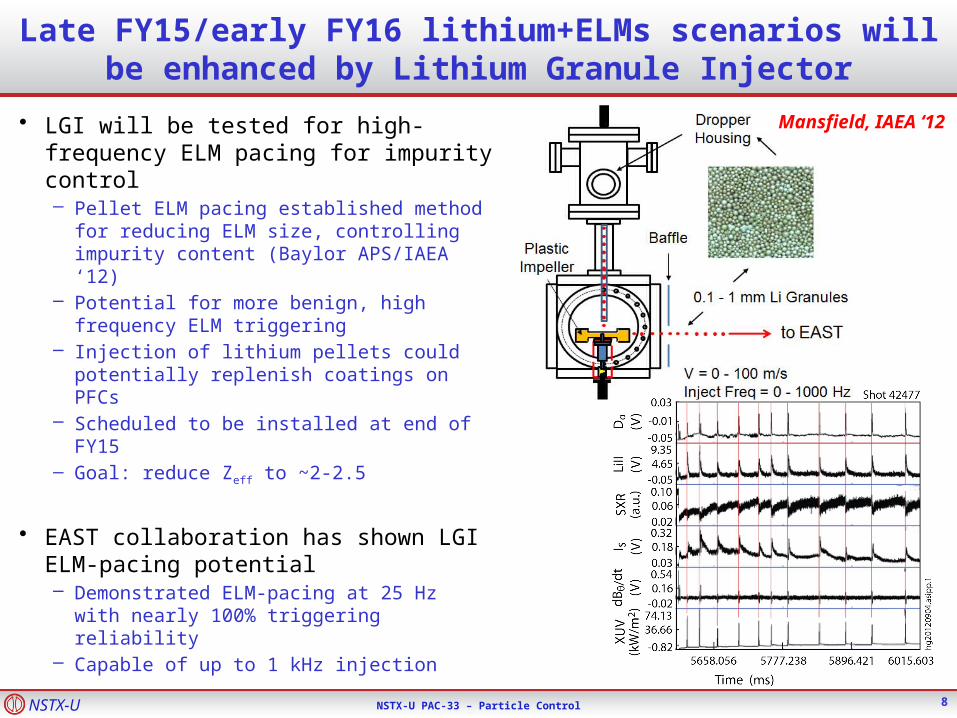
Late FY15/early FY16 lithium+ELMs scenarios will be enhanced by Lithium Granule Injector
• LGI will be tested for high-frequency ELM pacing for impurity control– Pellet ELM pacing established method
for reducing ELM size, controlling impurity content (Baylor APS/IAEA ‘12)
– Potential for more benign, high frequency ELM triggering
– Injection of lithium pellets could potentially replenish coatings on PFCs
– Scheduled to be installed at end of FY15
– Goal: reduce Zeff to ~2-2.5
• EAST collaboration has shown LGI ELM-pacing potential – Demonstrated ELM-pacing at 25 Hz
with nearly 100% triggering reliability– Capable of up to 1 kHz injection
8
Mansfield, IAEA ‘12
NSTX-U NSTX-U PAC-33 – Particle Control
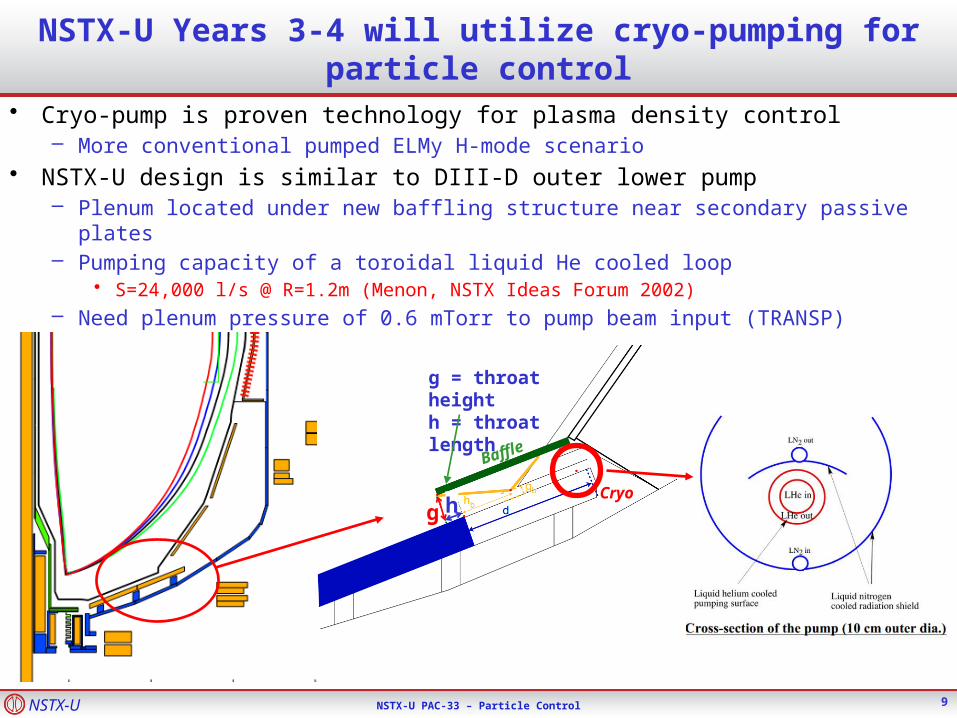
NSTX-U Years 3-4 will utilize cryo-pumping for particle control
• Cryo-pump is proven technology for plasma density control– More conventional pumped ELMy H-mode scenario
• NSTX-U design is similar to DIII-D outer lower pump– Plenum located under new baffling structure near secondary passive plates– Pumping capacity of a toroidal liquid He cooled loop
• S=24,000 l/s @ R=1.2m (Menon, NSTX Ideas Forum 2002)– Need plenum pressure of 0.6 mTorr to pump beam input (TRANSP)
g = throat heighth = throat length
9
g hCryo
Baffle

NSTX-U NSTX-U PAC-33 – Particle Control
Semi-analytic pumping model used to optimize plenum geometry
• Model developed for DIII-D pumping studies (Maingi, NF ‘99)– Predicts plenum pressure, validated with DIII-D data– Projected NSTX-U heat flux (Ip scaling) and divertor Te (~15 eV) used as input
– Uses first-flight neutral model (insufficient for detached divertor)
• Pressure is maximum for duct height g~2.5 cm, length h~2 cm– But is only weakly reduced if these are increased together
• With pump entrance at R=0.72m, pressures >1 mTorr can be reached over wide range of plasma shapes and SOL widths– Comparable to pressures in DIII-D plenum– Well above that needed to pump NBI particle input
10
+

NSTX-U NSTX-U PAC-33 – Particle Control
Optimized plenum geometry can pump to low density for conventional and snowflake divertors over a range of ROSP, Ip
• Core density estimated assuming pumped flux=NBI input– 2-pt model used to estimate
upstream density– Assume ne/ne
sep~3
• Can pump to fG<0.5– fG~0.7 desirable for all
scenarios, lower provides more flexibility
– Moving ROSP closer to pump allows lower ne, but limited by power handling
• High flux expansion in SFD gives better pumping with SOL-side configuration– More plasma in far SOL
near pump– More room to increase
ROSP at high Ip
11
0.4 0.6 0.8 1.0 1.2R (m)
-1.8
-1
.6
-
1.4
-1
.2
-
1.0
-0
.8Z
(m
)
qpk > 10 MW/m2
ROSP: outer strike point radiusRpump: plenum entrance radiusSD: standard divertorSFD: snowflake divertorfG: ne/nG
NSTX-U NSTX-U PAC-33 – Particle Control
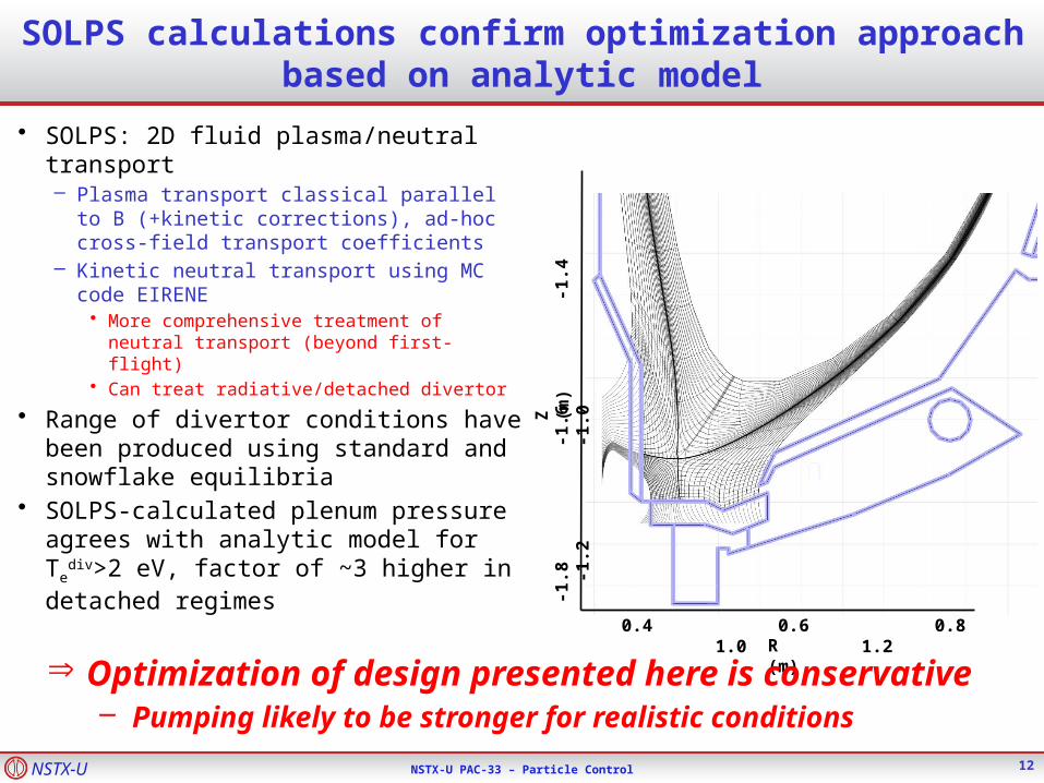
SOLPS calculations confirm optimization approach based on analytic model
12
• SOLPS: 2D fluid plasma/neutral transport– Plasma transport classical parallel to B
(+kinetic corrections), ad-hoc cross-field transport coefficients
– Kinetic neutral transport using MC code EIRENE
• More comprehensive treatment of neutral transport (beyond first-flight)
• Can treat radiative/detached divertor
• Range of divertor conditions have been produced using standard and snowflake equilibria
• SOLPS-calculated plenum pressure agrees with analytic model for Te
div>2 eV, factor of ~3 higher in detached regimes
0.4 0.6 0.8 1.0 1.2R (m)
-1.8
-
1.6
-1
.4
-1
.2
-
1.0
Z (
m)
Þ Optimization of design presented here is conservative– Pumping likely to be stronger for realistic conditions

NSTX-U NSTX-U PAC-33 – Particle Control
NSTX-U cryo experiments will support FNSF
13
• Flux expansion = 15-25, dx ~ 0.55• 1/sin(qplate) = 2-3
• Flux expansion = 40-60, dx ~ 0.62• 1/sin(qplate) = 1-1.5
Snowflake
Field-line angle of incidence at strike-point = 1˚
Conventional
• SOL-side pumping could enable FNSF– Compact FNSF designs leave little room for vertical target+dome for
ITER-like PFR pumping

NSTX-U NSTX-U PAC-33 – Particle Control
FNSF pumping trends are similar to those in NSTX-U design, projections will be improved by NSTX-U measurements
• Analytic model used to optimize geometry, with assumed Te(=5 eV) and q
• High pressures (>2.5 mTorr) are achievable with SOL-side pumping– With NSTX-U-like pumping speed, need to reach 0.5 (NNBI) to 2 (PNBI) mTorr– SD and SFD results are similar, since PFC geometry is altered to keep the plasma-wetted area
the same
• Achievable densities are promising– NNBI leads to fG<0.2 (compatible with Peng, FS&T ‘11 FNSF designs)
– For PNBI, fG~0.8 (sufficient for Menard, NF ‘11 ST-FNSF designs)
• NSTX-U will provide first results on density that can be achieved with an FNSF-like pumping system– Needed to benchmark and improve models for projecting the density and SOL width
14
NNBI: 0.5 mTorr PNBI: 2.0 mTorr

NSTX-U NSTX-U PAC-33 – Particle Control
NSTX-U particle control plans will develop and compare complementary approaches to particle exhaust
• FY14: remainder of NSTX-U outage– Begin engineering design of cryo, update physics as needed– Use EAST collaboration on lithium pumping, comparison with cryo– EAST collaboration on ELM-triggering with lithium granules
• FY15: initial NSTX-U operation with lithium– Re-establish lithium scenarios with triggered ELMs, extend to longer pulse– Get first divertor data in NSTX-U, confirm/finalize cryo design
• FY16: optimize lithium+ELM operation– Test pacing with lithium granule injector– Evaluate combinations of impurity reduction techniques
• FY17: test newly-installed cryo-pump– Characterize pressure, pumping, impact on density, compare to models– Develop strongly pumped scenarios
• FY18: routine use of cryo-pump in physics studies– Incorporate cryo into closed-loop density feedback control– Use pumping to control density in physics expts, e.g. for low * studies
15
NSTX-U NSTX-U PAC-33 – Particle Control
Summary: NSTX-U will test complementary methods for achieving particle control
• Lithium+ELM scenarios– Primary control technique in early NSTX-U operation– May benefit from LGI for improved ELM pacing
• Cryo-pumped ELMy H-mode– ELMy discharges with boronized PFCs to be developed in FY15/16– Cryo to be installed in outage prior to FY17 operations
• Goal for end of 5-year plan– fG ~ 0.5
– Zeff ~ 2-2.5
– Stationary density Up to an order of magnitude reduction in * compared to NSTX
16
NSTX-U NSTX-U PAC-33 – Particle Control
BACKUP SLIDES TO BE ADDED
• Previous PAC slides/APS talk on cryo details• EAST lithium slides• EAST dropper slides• FNSF details
17

NSTX-U NSTX-U PAC-33 – Particle Control
General layout similar to DIII-D lower outer cryo-pump system is taken as starting point for design analysis
• Plenum location studied: under new baffling structure
near secondary passive plates, possibly replacing
some outer divertor plates and tiles• Pumping capacity of a toroidal liquid He cooled loop
(Menon, NSTX Ideas Forum 2002)– S=24,000 l/s @ R=1.2m– Need plenum pressure of 0.83 mtorr
to pump beam input (10MW~20 torr-l/s)• Pumping rate:
– Ppl = plenum pressure
– I0 = neutral flux into plenum
– C = throat conductance
• To optimize, need C(g,h), I0(g,h)
g = throat heighth = throat length
SCS
ISPI plpump
0
18
g hCryo
Baffle

NSTX-U NSTX-U PAC-33 – Particle Control
Semi-analytic pumping model* used to optimize pumping chamber
• Uses first-flight model for neutral flux into pump plenum• Requires knowledge of divertor plasma profiles• Validated against DIII-D experiments
max
max
min
0
1max
max
00
00
1exp
tan;2
cos1
2
R
R EIIe
ent
m
R
R
effplpl
drrvrnv
rT
RR
gr
rrF
drRrTrFrI
C
C
CS
IP
CS
IP
*R. Maingi, Nucl. Fus. 39 (1999) 1187
Neutral current into plenum
Solid angle of plenum entrance
Transmission of neutrals through plasma
Origin of neutrals making it into plenum tends to be localized to near-entrance region Dominantly due to solid angle factor
Plenum pressure corrected for penetration of neutrals through long duct (verified using EIRENE)
19
NSTX-U NSTX-U PAC-33 – Particle Control
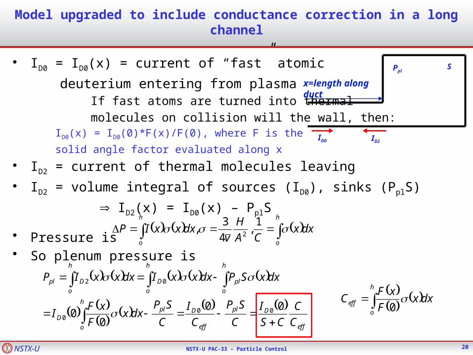
Model upgraded to include conductance correction in a long channel
• ID0 = ID0(x) = current of “fast” atomic
deuterium entering from plasma If fast atoms are turned into thermal
molecules on collision will the wall, then: ID0(x) = ID0(0)*F(x)/F(0), where F is the
solid angle factor evaluated along x
• ID2 = current of thermal molecules leaving
• ID2 = volume integral of sources (ID0), sinks (PplS)
ID2(x) = ID0(x) – PplS
• Pressure is• So plenum pressure is
PplS
ID0 ID2
dxxCA
H
vdxxxIP
h
o
h
o 1
,4
3,
2
eff
Dpl
eff
Dplh
o
D
h
o
pl
h
o
D
h
o
Dpl
C
C
CS
I
C
SP
C
I
C
SPdxx
F
xFI
dxxSPdxxxIdxxxIP
00
00 00
0
02
dxx
F
xFC
h
o
eff 0
x=length along duct
20
NSTX-U NSTX-U PAC-33 – Particle Control
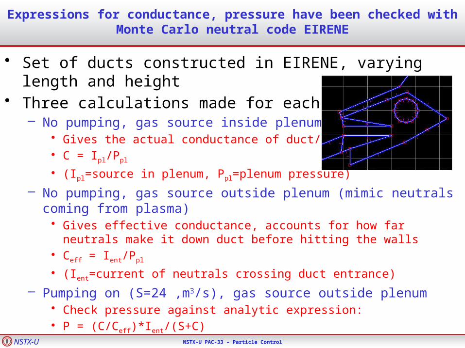
Expressions for conductance, pressure have been checked with Monte Carlo neutral code EIRENE
• Set of ducts constructed in EIRENE, varying length and height• Three calculations made for each:
– No pumping, gas source inside plenum • Gives the actual conductance of duct/aperture• C = Ipl/Ppl
• (Ipl=source in plenum, Ppl=plenum pressure)
– No pumping, gas source outside plenum (mimic neutrals coming from plasma)
• Gives effective conductance, accounts for how far neutrals make it down duct before hitting the walls
• Ceff = Ient/Ppl
• (Ient=current of neutrals crossing duct entrance)
– Pumping on (S=24 ,m3/s), gas source outside plenum• Check pressure against analytic expression: • P = (C/Ceff)*Ient/(S+C)
NSTX-U NSTX-U PAC-33 – Particle Control
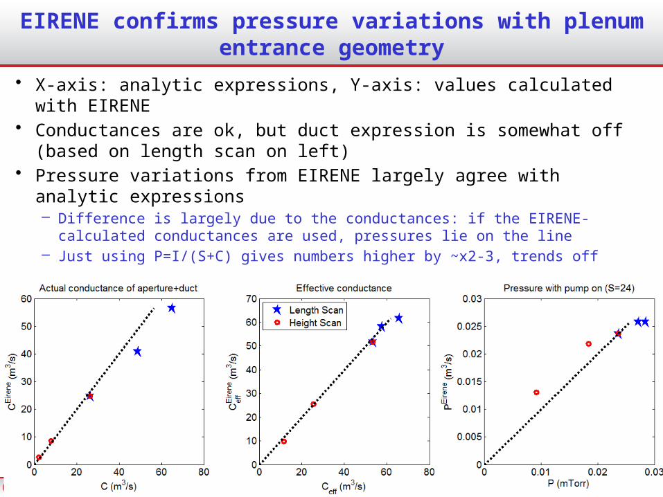
EIRENE confirms pressure variations with plenum entrance geometry
• X-axis: analytic expressions, Y-axis: values calculated with EIRENE• Conductances are ok, but duct expression is somewhat off (based
on length scan on left)• Pressure variations from EIRENE largely agree with analytic
expressions– Difference is largely due to the conductances: if the EIRENE-calculated
conductances are used, pressures lie on the line – Just using P=I/(S+C) gives numbers higher by ~x2-3, trends off

NSTX-U NSTX-U PAC-33 – Particle Control
Projected divertor parameters combined with semi-analytic pumping model are used to calculate pumping rates
• Analytic model requires divertor n, T, profiles
• Heat flux, angle of B wrt PFC surface (), and plasma temperature are sufficient to calculate n, :
– Recent experiments yield scaling of SOL heat flux width
• No-lithium scaling used here, but all trend towards q~3mm at Ip=2MA
• Pdiv = 5 MW assumed (1/2 of 10 MW input)
– Langmuir probes show Te~15-20 eV in far SOL, with lithium radial, Ip dependence
• Te~15 eV assumed (NSTX-U-like discharges)
mTn
Tq
2sin
7
NSTX shots with A=1.7 of NSTX-U
NSTX divertor scaling experiments

NSTX-U NSTX-U PAC-33 – Particle Control
Pressure projections are used to optimize plenum geometry parameters
• Exponentially decaying heat flux footprint imposed, with Te=15 eV
• Plenum entrance height, length are varied to maximize pressure• Pressure in optimized plenum depends primarily on heat flux at pump
entrance– Varied through ROSP, flux expansion or Ptot profile effects not important
– Reaching P~0.8 mTorr (to pump 10 MW NBI) requires qent~2 MW/m2
• Optimal plenum entrance for P=0.8mTorr: height g~2.5 cm, length h~2 cm
24
+
NSTX-U NSTX-U PAC-33 – Particle Control
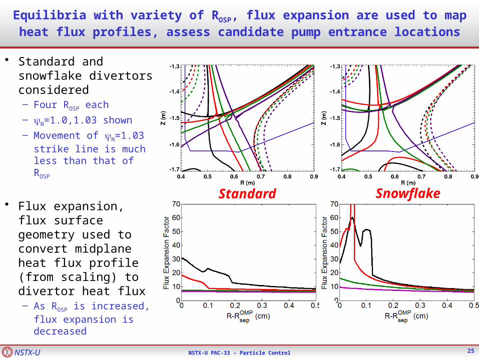
Equilibria with variety of ROSP, flux expansion are used to map heat flux profiles, assess candidate pump entrance locations
• Standard and snowflake divertors considered– Four ROSP each
– N=1.0,1.03 shown
– Movement of N=1.03 strike line is much less than that of ROSP
• Flux expansion, flux surface geometry used to convert midplane heat flux profile (from scaling) to divertor heat flux– As ROSP is increased,
flux expansion is decreased
Snowflake
25
Standard

NSTX-U NSTX-U PAC-33 – Particle Control
Realistic equilibria, heat flux scaling, and empirical TeSOL are
used to project plenum pressure for candidate location Rpump
• Analytic model for plenum pressure with optimized entrance parameters
• Pressure is non-monotonic with Rpump due to field geometry– At low Rpump, is lower, so
n/ is increased
more neutrals ionized before reaching pump
• Optimizing position for narrowest SOL gives Rpump~0.7
– Narrow SOL gives least flexibility in moving ROSP to improve pumping
– Rpump=0.72 gives high P for wide range of SOL width
26
STANDARD DIVERTOR P0

NSTX-U NSTX-U PAC-33 – Particle Control
Rpump=0.72 gives ne control for range of Ip, equilibria
• Modified 2-pt model used to estimate ne
sep
– q||sep from Ip scaling, Te
div varied
– Final nesep: pumping=NBI
input
• ne/nesep ~ 3 used to
estimate fG=n/nG
– Consistent with NSTX data
27
DIV
OMP
OMP
DIVDIVcalOMP
sep
eDIVOMP
B
B
T
Tnfn
LqTT
2
4
772
||0
27
SNOWFLAKE DIVERTOR n/nG

NSTX-U NSTX-U PAC-33 – Particle Control
Optimized plenum geometry capable of pumping to low density for a range of ROSP, Ip
• Equilibrium fG down to < 0.5– Moving ROSP
closer to pump allows lower ne, but limited by power handling
• High flux expansion in SFD gives better pumping with SOL-side configuration– More plasma in
far SOL near pump
– More room to increase ROSP at high Ip
28
0.4 0.6 0.8 1.0 1.2R (m)
-1.8
-1
.6
-
1.4
-1
.2
-
1.0
-0
.8Z
(m
)
qpk > 10 MW/m2
NSTX-U NSTX-U PAC-33 – Particle Control
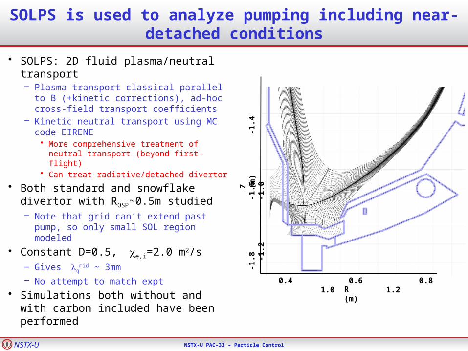
SOLPS is used to analyze pumping including near-detached conditions
• SOLPS: 2D fluid plasma/neutral transport– Plasma transport classical parallel to B
(+kinetic corrections), ad-hoc cross-field transport coefficients
– Kinetic neutral transport using MC code EIRENE
• More comprehensive treatment of neutral transport (beyond first-flight)
• Can treat radiative/detached divertor
• Both standard and snowflake divertor with ROSP~0.5m studied– Note that grid can’t extend past pump,
so only small SOL region modeled
• Constant D=0.5, e,i=2.0 m2/s– Gives q
mid ~ 3mm
– No attempt to match expt
• Simulations both without and with carbon included have been performed
0.4 0.6 0.8 1.0 1.2R (m)
-1.8
-
1.6
-1
.4
-1
.2
-
1.0
Z (
m)

NSTX-U NSTX-U PAC-33 – Particle Control
A wide range of divertor plasma parameters have been modeled
• Input power P=10MW in all cases
• ne at core grid edge set as boundary condition– Scanned to vary
divertor conditions
• Resulting divertor parameters vary from strongly attached to nearly detached (Te~1eV)
Midplane Divertor

NSTX-U NSTX-U PAC-33 – Particle Control
Snowflake shows higher plenum pressures that standard divertor for similar conditions
Standard Snowflake
• At same separatrix density, pressure is ~2x higher with Snowflake divertor configuration
• Partially due to geometry of field lines at pump entrance (plasma flux reaches nearer entrance; not accounted for in earlier projections)
• Pressures above 1 mTorr can be reached at high ne in both cases
NSTX-U NSTX-U PAC-33 – Particle Control
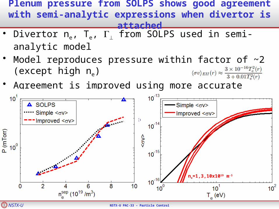
Plenum pressure from SOLPS shows good agreement with semi-analytic expressions when divertor is attached
• Divertor ne, Te, from SOLPS used in semi-analytic model
• Model reproduces pressure within factor of ~2 (except high ne)
• Agreement is improved using more accurate ionization rate– Simple rate coefficients used in original model: – Interpolating tables of v(ne,Te) as in EIRENE improves comparison
ne=1,3,10x1019 m-3

NSTX-U NSTX-U PAC-33 – Particle Control
Semi-analytic model underestimates pressure under detached conditions
• Model pressure close to SOLPS calculation for Te>2 eV– Often underestimates by
~50%– Model does not give large
overestimate in any cases
• For Te<2 eV SOLPS-calculated pressure is up to ~3x higher than model– First-flight neutral model
expected to break down– Consistent with DIII-D
pumping observationsÞ Optimization of design presented here is conservative– Pumping likely to be stronger for realistic conditions
NSTX-U NSTX-U PAC-33 – Particle Control
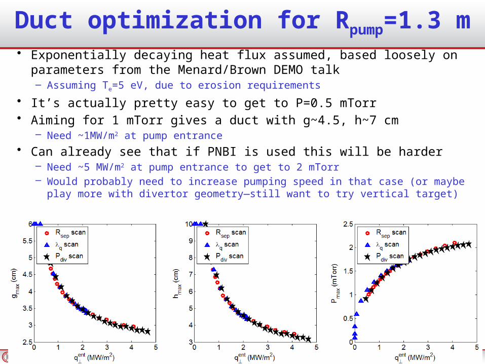
Duct optimization for Rpump=1.3 m• Exponentially decaying heat flux assumed, based loosely on parameters
from the Menard/Brown DEMO talk– Assuming Te=5 eV, due to erosion requirements
• It’s actually pretty easy to get to P=0.5 mTorr• Aiming for 1 mTorr gives a duct with g~4.5, h~7 cm
– Need ~1MW/m2 at pump entrance
• Can already see that if PNBI is used this will be harder– Need ~5 MW/m2 at pump entrance to get to 2 mTorr– Would probably need to increase pumping speed in that case (or maybe play more
with divertor geometry—still want to try vertical target)
NSTX-U NSTX-U PAC-33 – Particle Control
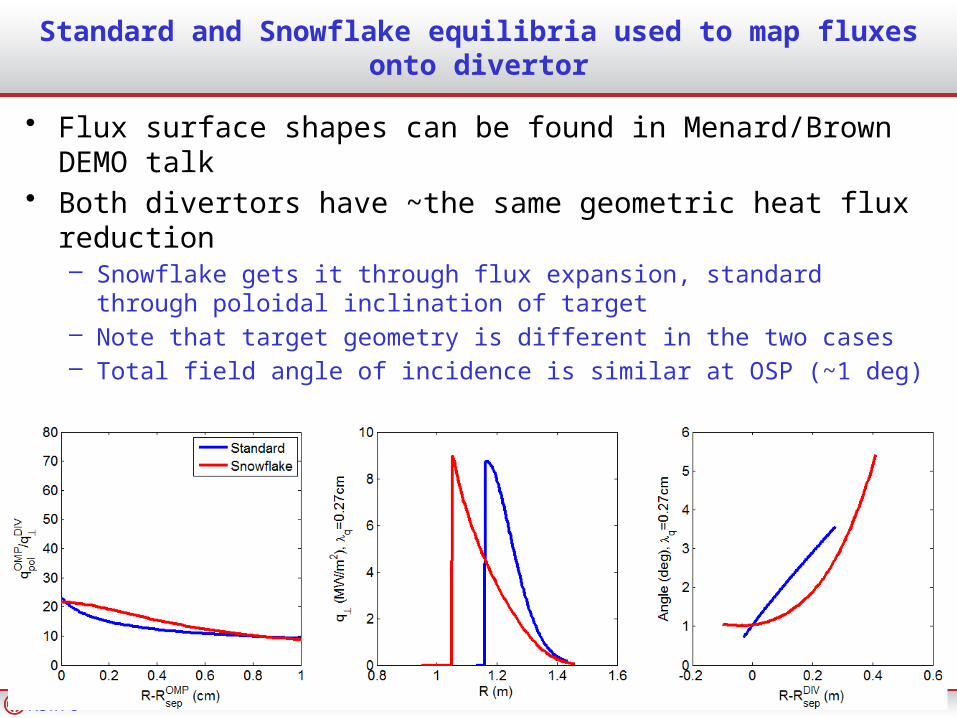
Standard and Snowflake equilibria used to map fluxes onto divertor
• Flux surface shapes can be found in Menard/Brown DEMO talk
• Both divertors have ~the same geometric heat flux reduction– Snowflake gets it through flux expansion, standard through poloidal
inclination of target– Note that target geometry is different in the two cases– Total field angle of incidence is similar at OSP (~1 deg)
NSTX-U NSTX-U PAC-33 – Particle Control
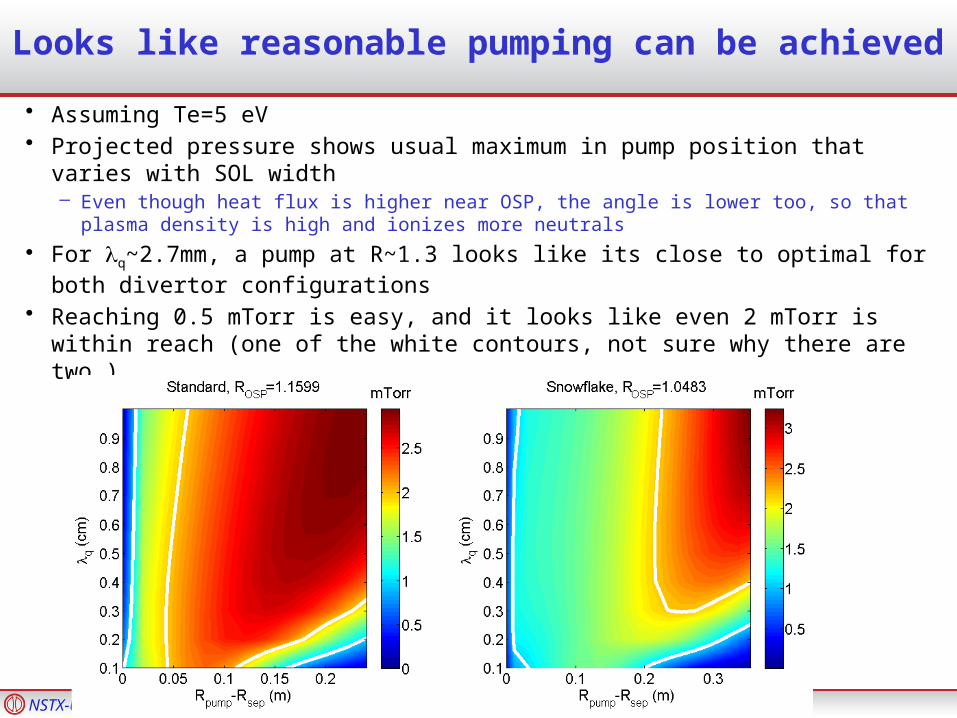
Looks like reasonable pumping can be achieved
• Assuming Te=5 eV• Projected pressure shows usual maximum in pump position that varies with
SOL width– Even though heat flux is higher near OSP, the angle is lower too, so that plasma
density is high and ionizes more neutrals
• For q~2.7mm, a pump at R~1.3 looks like its close to optimal for both divertor configurations
• Reaching 0.5 mTorr is easy, and it looks like even 2 mTorr is within reach (one of the white contours, not sure why there are two…)
NSTX-U NSTX-U PAC-33 – Particle Control
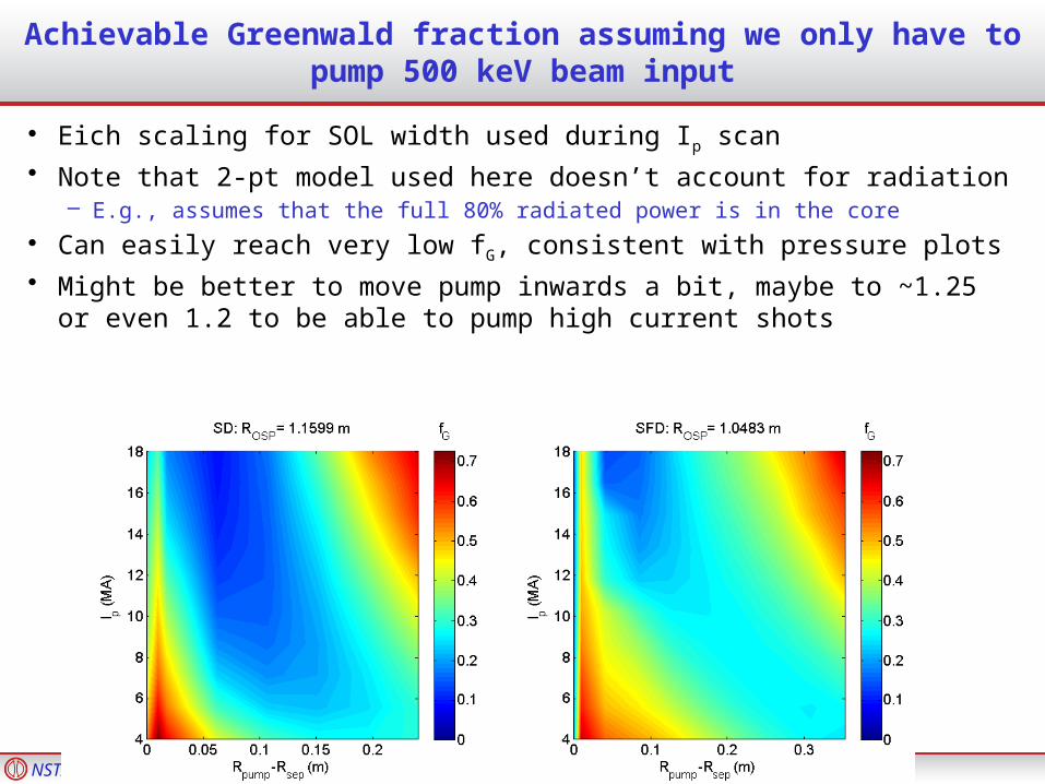
Achievable Greenwald fraction assuming we only have to pump 500 keV beam input
• Eich scaling for SOL width used during Ip scan
• Note that 2-pt model used here doesn’t account for radiation– E.g., assumes that the full 80% radiated power is in the core
• Can easily reach very low fG, consistent with pressure plots
• Might be better to move pump inwards a bit, maybe to ~1.25 or even 1.2 to be able to pump high current shots
NSTX-U NSTX-U PAC-33 – Particle Control
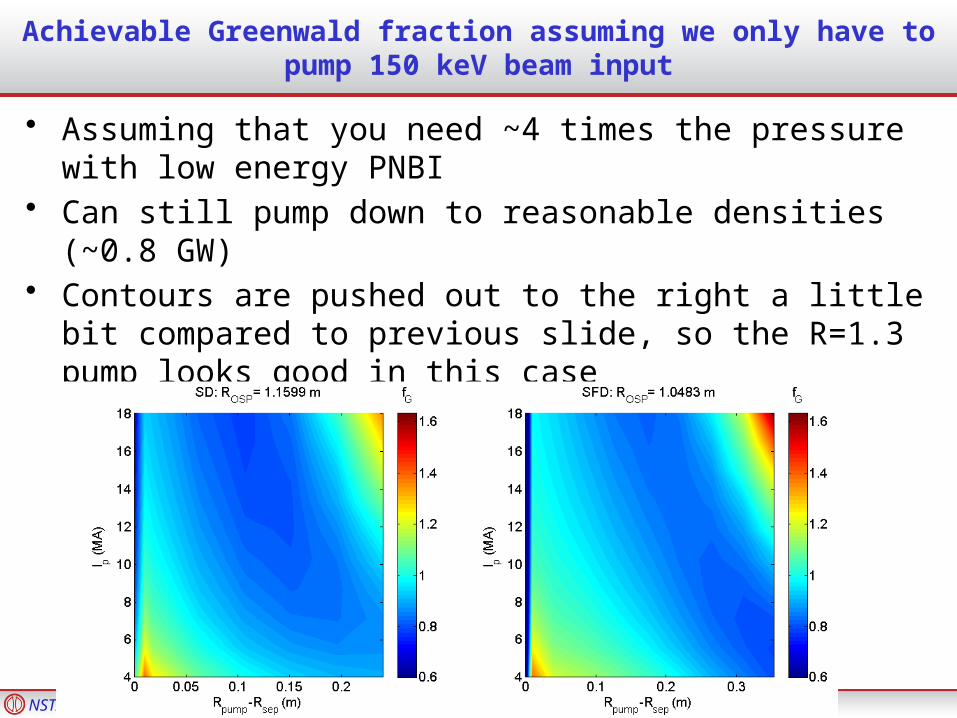
Achievable Greenwald fraction assuming we only have to pump 150 keV beam input
• Assuming that you need ~4 times the pressure with low energy PNBI
• Can still pump down to reasonable densities (~0.8 GW)• Contours are pushed out to the right a little bit compared to
previous slide, so the R=1.3 pump looks good in this case

NSTX-U NSTX-U PAC-33 – Particle Control
EASTEAST
Configuration of EAST shot 42477LSN during Li granule injection
2.0 m
88 mm
Impeller
Ti(0) ~ Te(0) ~ 1 keV
7

NSTX-U NSTX-U PAC-33 – Particle Control
EASTEAST
One sec injection @ 25 Hz of 0.7 mm Li granules at 52 m/s - shot 42477
400
0
0
0
0
1
100
6
2
0
Ip
LHCDICRF
MW
Da
kA
A.U
.
neL
kJ
Stored U
Time (s)
10
13m
-2
8

NSTX-U NSTX-U PAC-33 – Particle Control
EASTEAST
Examples of Triggered ELMsShot 42477
9
NSTX-U NSTX-U PAC-33 – Particle Control
EASTEAST
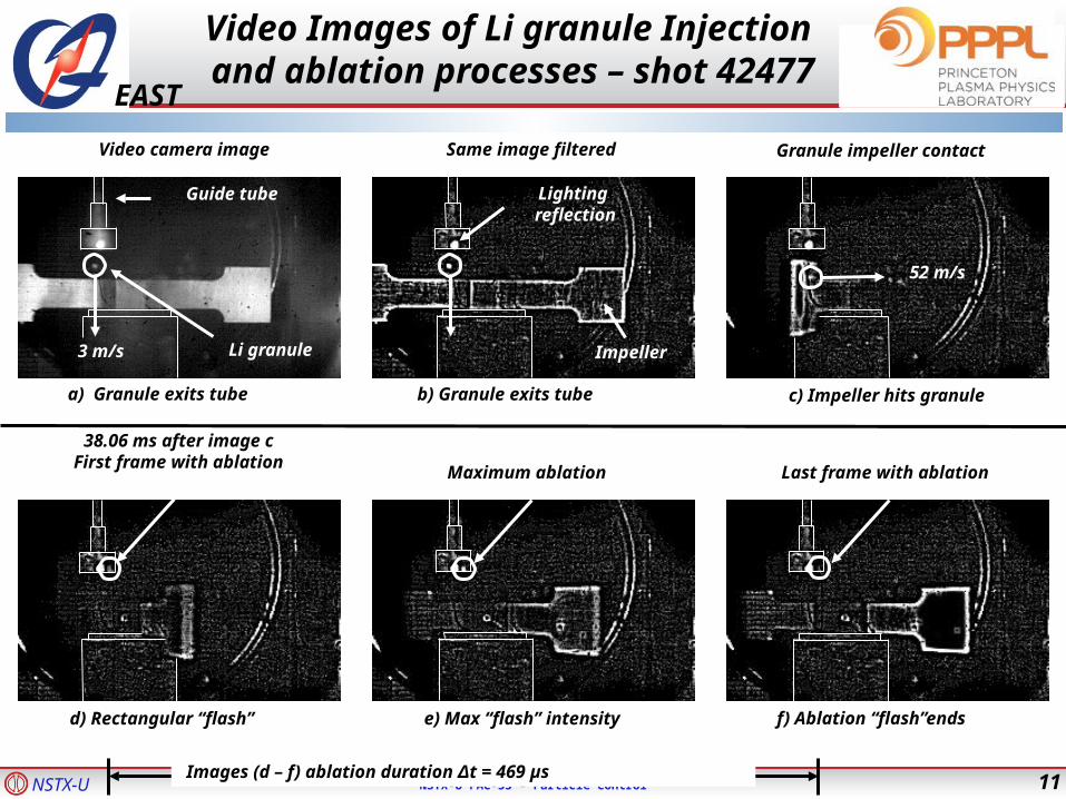
Guide tube
3 m/s Li granule
52 m/s
Granule impeller contactSame image filtered
Lighting reflection
Impeller
Video camera image
a) Granule exits tube b) Granule exits tube c) Impeller hits granule
Maximum ablation Last frame with ablation
38.06 ms after image cFirst frame with ablation
d) Rectangular “flash” e) Max “flash” intensity f) Ablation “flash”ends
Images (d – f) ablation duration Δt = 469 µs
Video Images of Li granule Injection and ablation processes – shot 42477
11

NSTX-U NSTX-U PAC-33 – Particle Control
EASTEAST
Video timing of Li granule injectionswith respect to 1st Granule
1071
1045
879
732
546
487
442
397
342
313
293
258
222
189
163
141
68.7
32.7
6.5
Δt (ms)
18
17
16
15
14
13
12
11
10
9
8
7
6
5
4
3
2
19
20
Granule #
12

NSTX-U NSTX-U PAC-33 – Particle Control
EASTEAST
Li granule injection timing on video versus edge XUV signal
Time (ms)
0 1000
XU
V (
a.u
.)
1071
1045
879
732
546
487
442
397
342
313
293
258
222
189
163
141
68.7
32.7
6.5
13


![fnsf] P]g g+= @! - mof.gov.npmof.gov.np/uploads/document/file/अन्तर... · 3 (घ) स्थानी तहले नो जन न क उठाउाँदा प्रदेशलेलगाएको](https://img.pdfslide.us/doc/110x75/5b9e89eb09d3f2fc778c1fae/fnsf-pg-g-mofgovnpmofgovnpuploadsdocumentfile.jpg)