Embed Size (px)
Citation preview

Developed under NSRP Systems Technology Panel
NSRP Systems Technology Panel Project
STEP-NC for Steel Production Final Report
Version 1.0
Abstract In 2006 ISO 10303 – 238(STEP-NC) was released as an international standard. Although the standard was not written specifically for the shipbuilding industry, this document proposes to extend the core of the specification to support the data requirements for Nesting and CNC operations used in the manufacturing of ship structural components. When integrated with other manufacturing-related STEP application protocols, the proposed STEP architecture provides a standards-based alternative to the outdated specifications now in place. Finally, this document examines the shipbuilding manufacturing environment and proposes a vision of how a centralized data architecture based on STEP and coupled with a rules-based framework can provide a consistent means of managing and accessing shipbuilding information.
Submitted by:
Kevin Richard - Northrop Grumman Corporation
Submitted on:
September 29, 2006
Category B - Approved for public release; distribution is unlimited

NSRP Systems Technology Panel Project STEP-NC for Steel Processing Final Report
i
Table of Contents 1 Introduction ............................................................................................................................... 1
1.1 Scope ................................................................................................................................. 1 1.2 Background ....................................................................................................................... 1 1.3 Problems Addressed.......................................................................................................... 2 1.4 Document Overview ......................................................................................................... 2
2 Applicable Documents, Reference, and Glossary ..................................................................... 3 2.1 Acronyms, Definitions, and Abbreviations ...................................................................... 3 2.2 Referenced Documents ..................................................................................................... 4
3 Context ...................................................................................................................................... 5 3.1 Nesting .............................................................................................................................. 6
3.1.1 Overview ................................................................................................................... 6 3.1.2 Input Requirements ................................................................................................... 7 3.1.3 Output ....................................................................................................................... 8
4 STEP Protocols to support Nesting/Cutting functions.............................................................. 9 4.1 STEP Overview .............................................................................................................. 10 4.2 STEP Application Protocols for Manufacturing ............................................................. 11
4.2.1 ISO 10303-218 ........................................................................................................ 11 4.2.2 STEP-NC ................................................................................................................ 15 4.2.3 ISO 10303-240 ........................................................................................................ 18
4.3 STEP Enhancements ....................................................................................................... 19 4.3.1 ISO 10303-218 Enhancements ............................................................................... 19 4.3.2 STEP-NC Enhancements ........................................................................................ 21 4.3.3 ISO 10303-240 Enhancements ............................................................................... 24
5 A STEP-based Environment ................................................................................................... 25 5.1 Application of Manufacturing Rules .............................................................................. 25 5.2 Central Data Repository .................................................................................................. 26
6 Conclusion .............................................................................................................................. 28

NSRP Systems Technology Panel Project STEP-NC for Steel Processing Final Report
Page ii
Table of Figures Figure 3-1 Structural Assembly ........................................................................................................ 5 Figure 3-2 Nested Geometry ............................................................................................................. 6 Figure 3-3 Nesting Input ................................................................................................................... 7 Figure 3-4 Nesting Output ................................................................................................................ 8 Figure 4-1 Applied STEP APs .......................................................................................................... 9 Figure 4-2 Shipbuilding Application Protocols .............................................................................. 10 Figure 4-3 ISO 10303-218 Entities ................................................................................................. 12 Figure 4-4 STEP-NC CC1 5-Axis test Parts ................................................................................... 15 Figure 4-5 STEP-NC Entities ......................................................................................................... 16 Figure 4-6 ISO 10303-240 Entities ................................................................................................. 18 Figure 4-7 Structural Features ........................................................................................................ 19 Figure 4-8 ISO 10303-218 Enhancements ...................................................................................... 20 Figure 4-9 STEP-NC Enhancements .............................................................................................. 23 Figure 4-10 ISO 10303-240 Enhancements .................................................................................... 24 Figure 5-1 Central Data Repository ................................................................................................ 26

NSRP Systems Technology Panel Project STEP-NC for Steel Processing Final Report
Page 1
1 Introduction
1.1 Scope This document serves as the final report for the NSRP Systems Technology Panel project – STEP-NC for Steel Processing. It includes a proposal for a STEP-based architecture to support Nesting and CNC control input for ship steel manufacturing using STEP-NC and other STEP manufacturing protocols.
The goal of this panel project was to answer the following questions:
1. Is STEP-NC a suitable specification to support the CNC control needs of the shipbuilding industry?
2. If so, are modifications required?
3. How can it be integrated into the ship manufacturing environment?
1.2 Background The predominant data standards used in the shipbuilding industry for input to CNC controllers for steel burning/cutting machines are ISO 6582 (ESSI) or RS 274D (EAI). The ESSI standard was originally developed by the Central Institute of Industrial Research in Norway and issued in 1983. RS 274D was developed in 1980 by the Electronic Industry Association. Both of these standards are used to specify tool head movement and other ancillary cutting machine functions which are typically referred to as ‘G’ and ‘M’ codes. Developers of Computer Aided Manufacturing (CAM) software applications have added non-standard enhancements to these specifications to support unique vendor features for specific CNC controllers and machines. As a result custom post-processing functionality is required to pass data to vendor-specific versions of each manufacturing control standard.
In 1995 the International Organization for Standardization (ISO) issued the initial release of ISO 10303 - Standard for the Exchange of Product Model data (STEP). STEP is a derivative of previous data formats including IGES, SET, and VDA-FS meant to support all aspects of technical product data. Domain-specific extensions to the standard are supported by STEP Application Protocols (AP). Each of these APs derives from a common set of STEP generic constructs that support model geometry, versioning, data relationships, and other data requirements. Over the past several years, APs were developed specifically for shipbuilding. These include: AP215 – Ship Arrangements, AP216 – Ship Moulded Forms, and AP218 - Ship Structures. These specifications primarily support ship preliminary design, detailed design, and manufacturing requirements.
While the shipbuilding STEP APs were being developed, work was also progressing on a STEP standard for CNC control for machined parts – ISO 14649 and STEP AP238, with references to STEP AP224, – collectively referred to herein as STEP-NC. The design of STEP-NC is a dramatic evolution to the G and M codes architecture in that it defers the generation of cutting tool path information to the CNC controller, providing information about the manufactured part in the form of manufacturing features. STEP-NC-enabled controllers thus choose the preferred method for producing the part based on the capabilities and state of the machine in use. Since only the part and the types of features required are included, STEP-NC data is more generic thereby enabling a single set of STEP-NC data to be used for multiple controllers, which obviates the need for non-value added, custom post processing routines.

NSRP Systems Technology Panel Project STEP-NC for Steel Processing Final Report
Page 2
1.3 Problems Addressed Answers to the first two questions to be addressed in this project are positive. STEP-NC can support shipbuilding CNC needs, but it will require some modification. One issue with incorporating STEP-NC into the shipbuilding domain is that STEP-NC, which currently supports turning, milling, and drilling operations, was not developed to directly support the requirements of ship steel manufacturing; primarily involving cutting and marking of large plate and structural profile parts. In order for the specification to be used effectively, it needs to be integrated with a feature-based source of manufacturing data. Manufacturing data is currently defined by STEP AP218 – Ship Structures, although this specification defines manufacturing information in a format more suitable to ESSI-based CNC controllers. If STEP-NC is going to be used, its modifications should be made concurrent with STEP AP218. Finally, since CNC operations also require production process information, it would be advantageous to harmonize the definition of process data with the product data and machine instructions defined by AP218 and STEP-NC.
Regarding question 3, integration of STEP NC into ship manufacturing requires looking at the issue from a macro level and deciding how best to incorporate these, and other relevant, emerging STEP standards into the shipbuilding lifecycle. This is a more general topic; this work will only address limited aspects of this issue. A conclusion of the present work is that adopting STEP-NC requires a broader incorporation of STEP into the shipbuilding lifecycle to enable the full benefit of the data standard. A large part of this benefit is the ability of an organization to choose among a variety of STEP-enabled systems.
1.4 Document Overview This document addresses the issues described above by discussing the context of a shipbuilding manufacturing environment, providing an overview of relevant STEP protocols as they are currently defined, and proposing modifications to these protocols to better support the incorporation of STEP-NC.
Section 3 is an overview of the functions associated with ship manufacturing to serve as a context to the nesting and manufacturing/fabrication operations. Focus is placed on the Nesting function as this has direct applicability to the proposed architecture. Here the data input and output requirements are stated.
Section 4 documents the relevant STEP application protocols in their current state as well as the proposed modifications
Section 5 is a discussion of the application of manufacturing rules within a centralized STEP-based data environment as an alternative to using STEP as solely a point-to-point exchange medium

NSRP Systems Technology Panel Project STEP-NC for Steel Processing Final Report
Page 3
2 Applicable Documents, Reference, and Glossary
2.1 Acronyms, Definitions, and Abbreviations AIM: Application Interpreted Model
AP: (Application Protocol); Documents that specify the format for representing product data within a set of related processes or activities.
API: Application Programming Interface
ARM: Application Reference Model
CAD: Computer Aided Design
CAM: Computer Aided Manufacturing
CNC: Computer Numerical Control
ESSI: ISO standard, developed in the 1980’s, for control of CNC burning machines
Express-G Graphical representation format used for displaying a STEP schema
IDE: Integrated Data Environment
IGES: Initial Graphics Exchange Specification
ISE: Integrated Shipbuilding Environment
ISEC: Integrated Shipbuilding Environment Consortium
ISO: International Organization for Standardization
ISO 10303-218: STEP AP: Ship Structures
ISO 10303-224: STEP AP: Mechanical product definition for process planning using machining features
ISO 10303-238: STEP AP: Application interpreted model for computerized numerical controllers
ISO 10303-240: STEP AP: Process plans for machined products
ISO 14649: Data model for computerized numerical controllers
NIDDESC: Navy Industry Digital Data Exchange Committee
NIST National Institute of Standards and Technology
NSRP: National Shipbuilding Research Program
OMAC Nonprofit organization dedicated to the development and use of open, interoperable control and automation system technologies (www.omac.org)
RS-274D: Also referred to as EAI – standard for numerically controlled machines developed by the Electronic Industry Association
SET: Standard d’Exchange et de Transfer
STEP: (STandard for the Exchange of Product Model Data); It is the familiar name given for the international standard ISO 10303 Industrial Automation Systems and Integration - Product Model Representation and Exchange. The objective is to provide a mechanism that is capable of describing product model data throughout the life cycle of a product. The standard is a collection of parts, each published separately.
VDA-FS: Verband des Automobilindustrie FlächenSchnittstelle
XML: Extensible Markup Language

NSRP Systems Technology Panel Project STEP-NC for Steel Processing Final Report
Page 4
2.2 Referenced Documents 1. M. Hardwick, B. Kassel, B. Crump, S. Garret, “Improving Shipyard Manufacturing Processes
using STEP-NC”, May, 2004
2. ISPE Final Report, Northrop Grumman Ship Systems, January 27, 2003, http://www.nsrp.org/projects/ispe_deliverables.html
3. ISO 10303-215 – “Application Protocol – Ship Arrangement”, International Standard, ISO TC184/SC4/WG3 N1226, 2004
4. ISO 10303-216 – “Application Protocol – Ship Moulded Forms”, International Standard, ISO TC184/SC4/WG3 N1133, 2003
5. ISO 10303-218 – “Application Protocol – Ship Structures”, International Standard, ISO TC184/SC4/WG3 N1350, 2004
6. ISO 10303-224 – “Application Protocol – Mechanical Product Definition for Process Planning Using Machining Features”, International Standard, ISO TC184/SC4/WG3 N1850, 2005
7. ISO 10303-238 – “Application Protocol – Application Interpreted Model for Computerized Numerical Controllers”, International Standard, ISO TC184/SC4/WG3 N2101, 2006
8. ISO 10303-240 – “Application Protocol – Process Plans for Machined Products”, International Standard, ISO TC184/SC4/WG3 N1469, 2005
9. ISO 14649 – “Industrial Automation Systems and Integration Physical Device Control-Part 10” ISO/TC 184/SC1/WG7 N 322, 2002
10. X.W. Xu, H. Wang., J. Mao, S.T. Newman, T.R. Kramer, F. M. Proctor, J.L. Michaloski, “STEP-compliant NC research: the search for intelligent CAD/CAPP/CAM/CNC integration”, International Journal of Production Research, Vol. 43, No.17, 1 September 2005, 3703-3743
NSRP Systems Technology Panel Project STEP-NC for Steel Processing Final Report
Page 5
3 Context Ship design and construction is an immensely complex task involving the coordinated efforts of multiple disciplines within the shipbuilding domain as well as outside vendors, contractors, and service providers. The following functions are a broad subset of the tasks involved in this effort:
Planning/Production Control
Manufacturing Engineering
Material Management
Manufacturing.
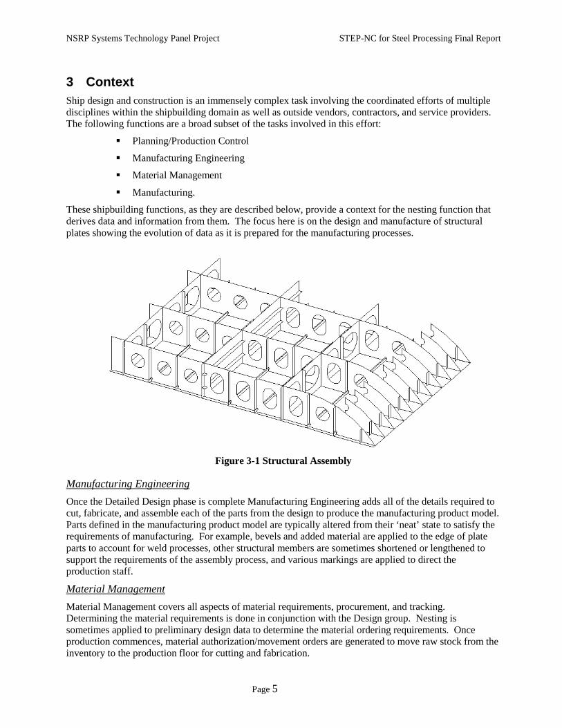
These shipbuilding functions, as they are described below, provide a context for the nesting function that derives data and information from them. The focus here is on the design and manufacture of structural plates showing the evolution of data as it is prepared for the manufacturing processes.
Figure 3-1 Structural Assembly
Manufacturing Engineering Once the Detailed Design phase is complete Manufacturing Engineering adds all of the details required to cut, fabricate, and assemble each of the parts from the design to produce the manufacturing product model. Parts defined in the manufacturing product model are typically altered from their ‘neat’ state to satisfy the requirements of manufacturing. For example, bevels and added material are applied to the edge of plate parts to account for weld processes, other structural members are sometimes shortened or lengthened to support the requirements of the assembly process, and various markings are applied to direct the production staff.
Material Management Material Management covers all aspects of material requirements, procurement, and tracking. Determining the material requirements is done in conjunction with the Design group. Nesting is sometimes applied to preliminary design data to determine the material ordering requirements. Once production commences, material authorization/movement orders are generated to move raw stock from the inventory to the production floor for cutting and fabrication.

NSRP Systems Technology Panel Project STEP-NC for Steel Processing Final Report
Page 6
Planning/Production Control Planning generates and maintains the ship production schedules, budgets, manufacturing bill of materials, and defines the assembly sequence and resource allocations for unit construction. Work is performed on the production floor through the issuance of work orders, which provide all of the information, together with Engineering documentation, necessary to complete a specific task.
Manufacturing The Manufacturing function includes all of the physical operations necessary to create a finished hull from raw material stock. Although there are many trades involved in this effort, for the purposes of this document, the manufacturing definition is constrained to the cutting, forming, and assembly of steel structural components with primary focus on cutting.
3.1 Nesting
Figure 3-2 Nested Geometry
3.1.1 Overview
The focus of this work is the Nesting function, specifically, the data required for and produced by Nesting. Nesting is the process of allocating individual or multiple plate parts to a piece of raw stock material. The parts are cut by a Computer Numerically Controlled (CNC) machine. Plate parts are nested based on common material type, thickness, and grain specifications and are sometimes grouped by their relation to an assembly hierarchy. That is, parts that are destined to be fabricated and assembled in a common assembly level are kept together. Nesting algorithms attempt to make maximum use of the surface area of the raw stock material by providing automated and semi-automated positioning. The end result of a nesting process is the positioning of one or more plate parts on a piece of material. Pre-nesting is performed early in the ship lifecycle to determine the amount of material required to be purchased for the ship and later the mold loft1 will nest parts based on the final design definition and produce the nest tapes2 used to drive the CNC controlled burning machines.
Nesting products typically have the additional capability of generating machine code to ‘direct’ a cutting tool on a CNC machine. For plate products, the format of this information is typically ISO 6582 (ESSI). Many NC plate cutting machines can also mark the surface of a plate using a variety of techniques to indicate part orientation and other assembly information. Marking information is included in the generated machine code. Finally, remnants from previous cutting operations can be reused and some nesting 1 The term ‘mold loft’, or ‘lofting’, refers to the group that generates the bulk of the information used by the production trades for cutting and fabricating parts. Historically, the term referred to an actual loft, where physical templates of parts were typically created for cutting. 2 Nest tape is a legacy term originally referring to the paper tapes, which were used to drive the NC machines. This term is still used to represent the data passed to a CNC controller.

NSRP Systems Technology Panel Project STEP-NC for Steel Processing Final Report
Page 7
software packages provide functionality to track and reuse this leftover stock material for subsequent nesting operations.
3.1.2 Input Requirements
Figure 3-3 Nesting Input
Figure 3-3 is a high-level diagram of the types of information required for the nesting process along with the functions that produce this data. This information is categorized as follows:
• Manufacturing Product Model
Includes:
Geometry Data: Geometry data consists of geometric entities that define part shapes, their associated features, marking, and labeling information. This report proposes that parametric, feature-based geometry be used whenever possible.
Engineering Data: Engineering data defines the required material type, thickness, etc. and the edge parameters of each part.
Processing Data: Processing data includes the information that is used to further direct assembly and fabrication operations such as marking, punching, and labeling information.
• Planning/Production Data
Includes:
Planning/Production data includes the schedules, resource allocations, part versioning, and quantity information, workstation, next higher assembly and process.
• Raw Material Data
Includes:
Raw material data defines the raw stock from which the parts are cut.
ManufacturingEngineering
Raw Stock InventoryMovement Orders
ScheduleResource AllocationsWork orders
Mfg Product ModelConstruction DwgsWork Packages Mfg Product Model
Planning/Production Data(Drawings, part revisions, etc.)
Raw Material Information
Planning/Production
Control
MaterialManagement
Nest Plates
NSRP Systems Technology Panel Project STEP-NC for Steel Processing Final Report
Page 8
3.1.3 Output
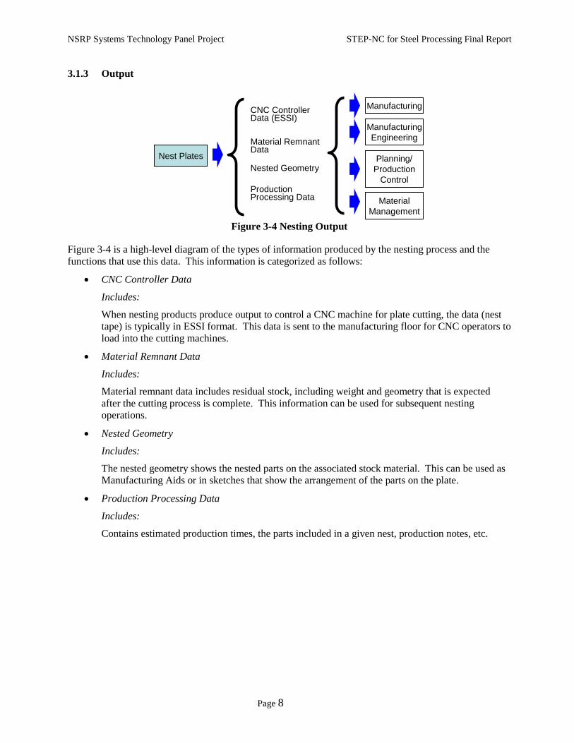
Figure 3-4 Nesting Output
Figure 3-4 is a high-level diagram of the types of information produced by the nesting process and the functions that use this data. This information is categorized as follows:
• CNC Controller Data
Includes:
When nesting products produce output to control a CNC machine for plate cutting, the data (nest tape) is typically in ESSI format. This data is sent to the manufacturing floor for CNC operators to load into the cutting machines.
• Material Remnant Data
Includes:
Material remnant data includes residual stock, including weight and geometry that is expected after the cutting process is complete. This information can be used for subsequent nesting operations.
• Nested Geometry
Includes:
The nested geometry shows the nested parts on the associated stock material. This can be used as Manufacturing Aids or in sketches that show the arrangement of the parts on the plate.
• Production Processing Data
Includes:
Contains estimated production times, the parts included in a given nest, production notes, etc.
Nest Plates
CNC Controller Data (ESSI)
Material Remnant Data
Nested Geometry
Production Processing Data Material
Management
Planning/Production
Control
ManufacturingEngineering
Manufacturing

NSRP Systems Technology Panel Project STEP-NC for Steel Processing Final Report
Page 9
4 STEP Protocols to support Nesting/Cutting functions This section proposes a STEP-based architecture to support the data requirements of the Nesting and NC control processes used in shipbuilding. The information provided is conceptual; the intent being to provoke further discussion among industry experts in related fields to continue to define, and refine, this approach. However, the architecture presented is only applicable to an environment in which STEP has been incorporated into a yard’s design and manufacturing lifecycle as the standard medium for exchanging data. Piecemeal adoption of STEP in this process will not provide the full potential of a consistent and standard means of sharing this information. Better still would be an architecture in which STEP data objects, as defined by all relevant STEP application protocols for shipbuilding, are maintained within a central repository accessed by a standard interface (see Section 5). Such are the capabilities of an Integrated Data Environment (IDE). Regardless, the benefits of this architecture diminish the further downstream STEP is applied to the process. Also, the use of STEP-NC is mandated by the existence and adoption of STEP-NC-enabled controllers. At the time this document was written, these types of controllers were mostly confined to the laboratory or other academic-related institutions.
Figure 4-1 Applied STEP APs
Figure 4-1 shows the mapping of STEP Application Protocols (AP) to the input and output requirements of the nesting process (see Section 3.1). ISO 10303-218 is used for capturing the bulk of the geometry and engineering data for manufacturing. ISO 10303-240 is used to define the manufacturing process planning and material management information. The nesting function uses STEP-NC-enabled CAM operations for producing input data for the CNC controllers. Finally, material remnant information, nested geometry and other production processing information is collected back into ISO 10303-240 constructs. The key aspect of this approach is that all input and output information refers to the same, feature-based geometry and manufacturing engineering data as defined in ISO 10303-218. To enable this, and to use ISO 10303-240 and STEP-NC in a shipbuilding manufacturing environment, modifications are required for each specification. This section provides an overview of these three STEP APs, as they’re currently defined, and proposes the required enhancements to each in order to support the nesting and manufacturing functions.
CNC Controller Data
Material Remnant DataNested Geometry
Production Processing Data
Nest Plates
AP2
18A
P240
STEP
-NC
AP2
40Planning/Production Data(Drawings, part revisions, etc.)
Raw Material Information
Mfg Product Model

NSRP Systems Technology Panel Project STEP-NC for Steel Processing Final Report
Page 10
4.1 STEP Overview The Standard for the Exchange of Product Model Data, better known as STEP, is an international standard for exchanging data between different CAD/CAM and Product Data Management (PDM) systems. STEP is an international standard (ISO 10303). Its evolution and development take place under the auspices of the International Organization for Standardization (ISO) Technical Committee 184, Subcommittee 4. STEP supports engineering, manufacturing, electrical/electronics, architecture and construction life cycle information (e.g. design, engineering, manufacturing and maintenance). Those portions of the STEP standard that have been identified as being of particular use to the shipbuilding industry for design phases of the lifecycle are shown in Figure 4-2.
Ship Structural Envelope Distribution Systems Equipment/Subsystems Miscellaneous
Ship ArrangementISO AP 215:2004
Ship Moulded FormsISO AP 216:2003
Ship StructuresISO AP 218:2004
Piping(Plant Spatial Configuration)
ISO AP 227:2001
Cable Trays(Plant Spatial Configuration)ISO AP 227 Edition 2
Parts LibraryISO 13584
Oil and GasISO 15926
AP 233 Systems Engineering Data Representation
AP 239 Product Life-cycle Support
Ship Product Model Data ExchangeISO TC 184/SC 4/WG 3
Computational Fluid Dynamics
ISO AP 237
•Ship Structural Envelope (hull form, arrangements, structure)•Distribution Systems (piping, electrical, HVAC, cable trays, mechanical)•Equipment/Subsystems
Mechanical Systems(Plant Spatial Configuration)ISO AP 227 Edition 2
HVAC(Plant Spatial Configuration)ISO AP 227 Edition 2
Logistics/SparesISO AP 232:2002
Electrical(Electrotechnical Design & Install)
ISO AP 212:2001
Finite Element Analysis
ISO AP 209:2001
AutomotiveISO AP 214:2001
Ship Structural Envelope Distribution Systems Equipment/Subsystems Miscellaneous
Ship ArrangementISO AP 215:2004
Ship Moulded FormsISO AP 216:2003
Ship StructuresISO AP 218:2004
Piping(Plant Spatial Configuration)
ISO AP 227:2001
Cable Trays(Plant Spatial Configuration)ISO AP 227 Edition 2
Parts LibraryISO 13584
Oil and GasISO 15926
AP 233 Systems Engineering Data Representation
AP 239 Product Life-cycle Support
Ship Product Model Data ExchangeISO TC 184/SC 4/WG 3
Computational Fluid Dynamics
ISO AP 237
•Ship Structural Envelope (hull form, arrangements, structure)•Distribution Systems (piping, electrical, HVAC, cable trays, mechanical)•Equipment/Subsystems
•Ship Structural Envelope (hull form, arrangements, structure)•Distribution Systems (piping, electrical, HVAC, cable trays, mechanical)•Equipment/Subsystems
Mechanical Systems(Plant Spatial Configuration)ISO AP 227 Edition 2
HVAC(Plant Spatial Configuration)ISO AP 227 Edition 2
Logistics/SparesISO AP 232:2002
Electrical(Electrotechnical Design & Install)
ISO AP 212:2001
Finite Element Analysis
ISO AP 209:2001
AutomotiveISO AP 214:2001
Figure 4-2 Shipbuilding Application Protocols
Further information about the Shipbuilding APs is available at http://www.nsrp.org/t23/ship-soap.pdf and general information about the advantages and uses of the STEP standard in all industries is available at http://www.tc184-sc4.org/SC4_Open/SC4_Standards_Developers_Info/Files/step02-04.pdf.
To use STEP, a company must have software capable of translating files in and out of the proprietary formats of the CAD/CAM or PDM systems it uses and into the neutral format created by STEP. Leading manufacturers of CAD/CAM systems are adapting their products to work with STEP.
The STEP Application Protocols determine what STEP-conformant tools can do. Each Application Protocol defines all the data needed for a particular application domain. To be STEP-conformant, software systems have to be able to support all the data defined by the Application Protocol. This ensures that all data can be translated in and out of this format without any loss.3
3 Industry Canada, Aerospace and Defense Branch; “Introducing STEP”; http://strategis.ic.gc.ca/epic/internet/inad-ad.nsf/en/ad03581e.html.

NSRP Systems Technology Panel Project STEP-NC for Steel Processing Final Report
Page 11
Each Application Protocol is documented using a common organization of Clauses for various end-users of the standard. Clause 1 defines the scope of the application protocol and summarizes the functionality and data covered by the AP. Clause 3 lists the words defined in the AP and gives pointers to words defined in other standards. The information requirements of the application are specified in clause 4 using industry terminology appropriate to the application. A graphical representation of the information requirements, referred to as the application reference model (ARM), is provided. In most APs, an ARM model in the computer-interpretable EXPRESS language is also provided.
Resource constructs defined in other portions of the STEP standard, known as the Integrated Resources, are used by all of the STEP APs to produce software implementations that are similar and interoperable across different industries and application domains. The “interpretation” of these common integrated resources through a Mapping Table produces the application interpreted model (AIM). The Mapping Table of the AP shows the correspondence between the information requirements of the ARM with the resulting implementable model of the AIM. The AIM is the data model used by STEP software developers to communicate the AP’s industry-specific data requirements in a set of data entities that cross all domains and industries. Using this common set of entities enables interoperability between APs, and greatly reduces software development efforts by allowing reuse of large portions of translator software code.
For the remainder of this document, the data entities discussed within each AP refer to the ARM representation, i.e., that portion of the AP that uses shipbuilding industry terminology.
4.2 STEP Application Protocols for Manufacturing This section provides an overview of three manufacturing-related APs and a description of the entities within each that are relevant to the Nesting function.
4.2.1 ISO 10303-218
ISO 10303-218 Ship Structures is one of a number of ship building specific application protocols used for capturing production model information for the design and construction of ship structural components. ISO 10303-218 covers a broad area of the ship building lifecycle including preliminary design, detailed design, and manufacturing. Included in the specification are constructs to support: work flow related functions (change and configuration management, approvals, and rejections), ship general characteristics (type, class, weights), and hull stress calculations (bending and shear forces). The bulk of the ISO 10303-218, however is for defining ship structural information from detailed design and manufacturing perspectives.
Development of ISO 10303-218 began in 1991 and is based on work completed by the Navy Industry Digital Data Exchange Committee (NIDDESC) by representatives of the major US shipyards and NAVSEA who had previously worked on IGES data exchange for the Seawolf and DDG51 ship construction programs. The work was principally accomplished by Newport News Shipbuilding and Kockums Computer Systems of Malmo, Sweden and Hamburg, Germany. The design of the specification is based on the then-current and foreseen CAD technology for structural part design and manufacturing. The state-of-the-art Ship Design systems of the time were just beginning to use feature-based design for structural product models, in which the molded surface geometry for the ship decks and bulkheads were modified to create “neat” design parts with the “smart” CAD system accounting for part geometry modifications due to plate thicknesses and offsets, relationships with intersecting parts for generation of stiffener cutouts, parametric location of drain holes and the like. The knowledge of these product model relationships and ability to “automatically” create the neat design part geometry from material attributes, intersecting structural systems, and parametric design rules became the “implicit” definition for structural plate and profile parts in ISO 10303-218. A set of Structural features that parametrically define the geometry for items such as stiffener cutouts, access holes, drain holes, edge bevels and chamfers were included in these STEP object definitions. These “design definitions” for the structural features represent

NSRP Systems Technology Panel Project STEP-NC for Steel Processing Final Report
Page 12
the ideal feature geometry before accounting for any production engineering modifications such as changes to hole diameters to allow for coaming installation, weld bevels and root gaps and the like. In essence, the structural part design definitions provided in ISO 10303-218 allow exchange of the product model design data at the point when detail design ends and production engineering begins. In addition to this detailed design structural part data, ISO 10303-218 contains a simplified manufacturing definition for each structural part. This manufacturing representation for each plate and profile part allows exchange of the part geometry after the yard-specific manufacturing decisions have been applied to modify the “neat” design definition for the individual yard’s manufacturing operations. It is based on the nesting and cutting controller systems in general use at the major US shipyards during development of the ISO 10303-218 standard, which are still in wide use today. The manufacturing representation consists of the outer and inner burn geometry, marking lines and text marking based on the requirements of ESSI plate and profile cutting controllers.
Figure 4-3 ISO 10303-218 Entities
Over the last few years, advances have been made in nesting systems and cutting controllers to begin using feature-based manufacturing of ship parts similar to the technology available for mechanical part manufacturing. For example, pockets and holes can be milled or drilled from parametric definition of the feature geometry as a location, angle, diameter and depth, rather than by specification of the exact controller head movement. The processing of these parametric feature manufacturing instructions are becoming more a function of the controller’s built-in intelligence rather than machine instructions produced within the CAD or nesting system software. As these advanced controllers come to market, it will be possible to modify the manufacturing definition for plate and profile parts in ISO 10303-218 to support this change in manufacturing technology.
Plate
Design_definition
Item
Profile
Interior_cutout
Structural_cutout
FeatureFeature PartPart
Structural_feature Structural_partStructural_part
Edge_feature
Edge_cutout
Corner_cutoutFeature_design_definition
Manufacturing_definition
Structural_part_manufacturing_definition
Plate_manufacturing_definition Profile_manufacturing_definition
Structural_part_design_definition
Profile_design_definition Plate_design_definition
defined_fordefined_for
defined_for defined_for
Corner_cutout_design_definition
Bevel_design_definition
Part_edge_cutout_design_definition
Interior_cutout_design_definition
defined_for
defined_for
defined_for
defined_for

NSRP Systems Technology Panel Project STEP-NC for Steel Processing Final Report
Page 13
The schema for defining detailed design and manufacturing information is based on the definition and relationship of three main types of entities: items, design definitions, and manufacturing definitions (Figure 4-3). Items represent individual instances of elements within a structural envelop. Types of items in a structural model include structural parts (e.g., plates, profiles, assemblies) and structural features (e.g., weld/fabrication information, internal/edge cutouts). Design definition data captures all the information necessary for the complete definition of the structural components of a ship. In a feature-based design, structural features, such as interior and edge cutouts and preparations, are defined parametrically and associated to their corresponding design items. For example, a center location and radius parametrically define a circular hole, and profile cross-section dimensions parametrically define a stiffener penetration along the plate’s edge. In the case of the design definition, each of these feature’s geometric representation are independently referenceable within the STEP data. Instances of like features are derived from a common source thus simplifying the geometry model and making it possible to utilize feature libraries, which allow a single geometry representation to be shared across various design elements. Also, defining individual features in a model allows them to be further characterized by their function.4 Having feature-based entities, within a design and manufacturing model, is paramount if a structural model is to be used as a basis for STEP-NC.
Whereas the design model within ISO 10303-218 defines the completed physical shape and properties (e.g., material type and thickness) of a part, the manufacturing model defines all of the information necessary to create, fabricate, and assemble these parts. The manufacturing definition for each plate and profile part is defined using two-dimensional part geometry in preparation for manufacturing with legacy ESSI-based plate cutting systems. In this representation, any curvature in the plate has been expanded, and the geometry from each feature has either been melded into the “outer burn” geometry of the part, or included as a member of the set of geometry slated to be manufactured as “inner burns” or “marking lines.” The manufacturing process for steel plate parts is summarized as follows:
The process starts with raw material. Using various types of cutting equipment each individual plate part is cut from larger raw plate stock. Plate parts that are used in the construction of bulkheads and decks are typically kept flat whereas plates used in the construction of the hull can be flat, bent, or curved. Curved and bent plates require additional fabrication steps in order to get the flat material into its final form. Individual plate parts that are part of larger panel assemblies are welded together at their seams, which may require additional fabrication steps to account for the requirements of the welding process and/or other connection details at the joint. Plates also typically have supporting structural material (e.g., stiffeners, chocks, brackets) welded to them. Manufacturing aids, in the form of marking lines, labels, and symbols are physically located on the plate’s surface. This information is either placed manually or as part of the automated cutting process and can either be etched or marked with a variety of materials. The outer contour of the plate is typically adjusted to account for fit-up, shrinkage due to welding, and/or for a forming allowance.
Typical manufacturing information needed for an NC burning operation includes:
• The geometry defining the shape of a part
This includes the interior sections that are removed by the burning process.
• Marking/labeling information
This is required since this information can be applied by the NC machines.
• Details about the edge surface preparations including bevels
• Near/far side information to determine which side marking/labeling information is applied
4 As is done with the functional definition model with the AP218 specification
NSRP Systems Technology Panel Project STEP-NC for Steel Processing Final Report
Page 14
• Material information to determine raw stock.
• Tabbing/bridging, which is material left by the burner so that parts do not drop after being cut
• Access to revision data
This is critical since the design could have evolved between the time the NC data was created and the time of the cutting
• Unit of measure
• Accuracy control information
In the years since the development of the initial version of ISO 10303-218, considerable progress has been made in upgrading manufacturing NC controllers used by the shipbuilding industry to add burning capabilities which are similar to those used for multi-axis machining, milling and drilling of small metallic parts. In these new systems, manufacturing instructions for each individual feature to be subtracted from the plate stock material are now possible, as is multi-axis control of torches to create complex weld bevels on the outer plate edges in a single operation. The existing plate and profile manufacturing definitions provided in the initial publication of ISO 10303-218 will continue to be useful for many years to come for structural part manufacturing using ESSI-based legacy systems, but modifications are recommended for a revised version of ISO 10303-218 to also support the latest nesting systems and NC controllers.

NSRP Systems Technology Panel Project STEP-NC for Steel Processing Final Report
Page 15
4.2.2 STEP-NC
STEP-NC, is a data schema to support the control of CNC machines. It represents a dramatic evolution to the current toolpath-based languages used today – the so-called G & M codes. STEP-NC began as a joint European and Japanese venture in the development of ISO 14649. The European ESPRIT STEP-NC project validated the ARM models and produced milling test implementations. It ran from January 1999 to December 2001 and brought together 20 industrial and academic partners with experience in CAD, CAM, control systems, and machine tools. Additional validation was performed by the National Research Lab for STEP-NC Technology at the Pohang University of Science and Technology in Korea, who implemented an intelligent control system that operates on STEP-NC data.
Figure 4-4 STEP-NC CC1 5-Axis test Parts
In the United States, the ARM and AIM were validated by the Model Driven Intelligent Control of Manufacturing (MDICM) project, a three-year project awarded to STEP Tools by the National Institute of Standards and Technology (NIST) in 1999. The project produced test implementations, held five internal demonstrations from 1999 to 2003, and established an Industrial Review Board (IRB) consisting of Fortune 500 companies, software developers of CAD and CAM products, machine tool manufacturers, job shops and industry experts and consultants. In 2005 the OMAC STEP-NC Working Group hosted an ISO 10303-238 testing forum in Orlando to demonstrate 5-axis parts machined using AP238 CC1 machine independent toolpaths (Figure 4-4). Four CAD/CAM systems produced. ISO 10303-238 machining programs for milling 5-Axis test parts. Each of these was then run on a pair of CNC machines configured for completely different machine geometries (AB tool tilt vs. BC table tilt). In addition, Boeing cut actual parts on a variety of machines at the Tulsa facility as well as a machine at NIST in Gaithersburg.

NSRP Systems Technology Panel Project STEP-NC for Steel Processing Final Report
Page 16
STEP-NC defines the piece to be manufactured as a collection of separate manufacturing features. Each feature has one or more machining operations that are used to create it. Machining operations define the processes and supporting information that a NC controller needs in order to complete the operation. The underlying data model for STEP-NC is ISO-14649, which provides the ARM representations (see Section 4.1). ISO 10303-238 provides the AIM. Both of these standards refer to ISO 10303-224 for descriptions of manufacturing/machining features, tolerance data, and tool paths.
Figure 4-5 STEP-NC Entities
Referring to Figure 4-5, the STEP-NC data architecture starts with a project definition, which associates a work plan with a work piece – an object to manufacture. Work plans are further defined as a collection of:
• Machining working steps (described in more detail below),
• NC functions
NC Functions identify secondary machine operations such as a program stop, tool load, message display, etc.
• Logic operations5
Logic operations allow a controller to branch its processing based on the result of a particular test, such as a probing function
• Other work plans
The relationship of nested work plans provide a means of defining a hierarchy of operations, with each sub-level consisting of finer-grained operations
5 These are defined in the specification as ‘program_structure’. This document groups the elements with the program_structure as logic-based operations.
Workpiece
Machining_workingstep
Workplan
Machining_operation
Machining_Tool
Technology
Toolpath
Project
Manufacturing_feature
Logic NC_function
Machining_functions
Workplan

NSRP Systems Technology Panel Project STEP-NC for Steel Processing Final Report
Page 17
Machining working steps define the bulk of the machine operations (including the order in which they proceed)6 necessary to create a work piece, one feature at a time. Each machining operation is further defined by its function, technology, tool and optionally a specific tool path. The machining operations and technology define characteristics of the cutting process that are specific to the processes used (e.g., the application of coolant, feed rate, etc.). The machining tool identifies the requirements of the implement used in the cutting process. Finally, a machining operation can provide an explicit path for the cutting tool to follow. This was incorporated into the specification to handle the more complex cutting operations.
In contrast to defining an explicit tool path, which an NC controller must ‘blindly’ follow to create a part, a STEP-NC data file provides information about the part itself, letting the controller decide how best to direct the machine. STEP-NC data is thus less machine/controller-specific allowing a single STEP-NC file to be used on multiple machines, each having separate capabilities and input requirements. From a data interoperability perspective, this benefit obviates the need to post-process CAM data to suit the specific input requirements of various equipment in a shop. In addition, breaking down the machine operations by feature provides an explicit mapping of machine operation to the section of the work piece being cut (feature). One could envision a STEP-NC compiler drawing from a resource of common features in the generation of STEP-NC data. Diagnostics from the actual cutting operation could then be fed back into the library and used to tune future operations. Finally, since a STEP-NC file shares the same geometry definition with other STEP APs, currently in broad use, the transition to a STEP-NC data file from design source defined in other STEP formats is more efficient.
STEP-NC, as it is currently defined, contains support primarily for milling and turning operations. From a shipbuilding perspective, these operations only satisfy a fraction of the manufacturing requirements. The next section of this document proposes to expand the core of the STEP-NC specification to incorporate the needs of steel plate and profile cutting.
6 Note that the machining working steps are a derivative of a working step, which define other types of operations such as probing and rapid tool movement.

NSRP Systems Technology Panel Project STEP-NC for Steel Processing Final Report
Page 18
4.2.3 ISO 10303-240
ISO 10303-240 is used to define a manufacturing process plan for creating machined parts. Like STEP-NC, ISO 10303-240 associates manufacturing processes with individual features for a particular part. ISO 10303-240 however is used for process planning at a more macro level and can reference STEP-NC data for individual machine instructions for each processing step. Also, ISO 10303-240 can refer to and/or define non-machining/manual processes making it a candidate medium for defining macro planning data for the shipbuilding manufacturing lifecycle. Figure 4-6 shows an Express-G representation of a subset of the high-level entities, and their interrelationships, defined by ISO 10303-240. Only the entities that directly pertain to shipbuilding and the scope of this report are included.
Figure 4-6 ISO 10303-240 Entities
ISO 10303-240 defines a process plan (Process_plan_version), which identifies an ordered set of manufacturing processes for fabricating a versioned part (Single_piece_part or Manufactured_assembly). Process plans can contain version information. Manufacturing processes are further defined as being machined or non-machined and identify an ordered set of manufacturing activities, setup parameters/activities, and a description. Similar to STEP-NC, a manufacturing process in ISO 10303-240 can associate an ordered set of manufacturing activities with a set of manufacturing features. The connection between a manufacturing process and a set of features is optional in ISO 10303-240, however. Machining processes identify the machine on which the feature(s) is/are to be cut.
The details for cutting are defined by a manufacturing activity. Manufacturing activities can be further defined as being validation, part routing, part mounting and unmounting, or other process-related activities in which finer-grained details of the process are defined. Activities are also used to allocate material and production resources such as a facility, locations within a facility, and individual equipment at a location. Finally, each activity is assigned a duration, which can either be a total time allotment or an allotment per unit of quantity. For the purposes of this document ISO 10303-240 will be discussed in regards to manufacturing planning alone and will defer the manufacturing details to STEP-NC data.
Process_plan_version Activity
Controller_programPart_versionPart_version
Single_piece_partSingle_piece_part
MaterialMaterial
Manufacturing_processManufacturing_process Manufacturing_activity
Generic_manufacturing_resourceGeneric_manufacturing_resource
Machining_process External_schema_def.
Revision
Process_plan_security
Work_Cell
Performance_rate
Process_activity
Validation
Part_routing
Part_mounting
Part_unmounting
Machine_setup
Machine
In_facility_locationIn_facility_location
Non-machining_processNon-machining_process
L[1:?]

NSRP Systems Technology Panel Project STEP-NC for Steel Processing Final Report
Page 19
4.3 STEP Enhancements This section proposes enhancements to the three STEP APs described in Section 4.2 to support their coordinated use in the nesting and cutting of ship structural parts.
4.3.1 ISO 10303-218 Enhancements
The modifications recommended for a second version of ISO 10303-218 should adopt the style of the Application Interpreted Model of ISO 10303-224, the STEP specification for feature-based machining of small mechanical parts, as this is the standard of choice for implementation by the NC controller manufacturers. The new ISO 10303-218 feature-based manufacturing definition would consist of a three dimensional solid representation of the plate or profile part stock from which a single part or nest of parts is to be manufactured. Each of the existing ISO 10303-218 structural features would be augmented with a separately referenceable feature manufacturing definition, which would contain its own parametric solid representation of the volume to be subtracted from the part stock for manufacturing of the feature. These parametric definitions would be related to the existing ISO 10303-218 feature design definitions, so that the detail design geometry could be used without modification for manufacturing if appropriate, or alternatively to allow the design parameters to be modified to apply additional yard-specific or machine-specific manufacturing rules. In many cases, the existing 10303-218 feature design definitions will require minimal modification for use as manufacturing definitions for feature-based controllers. Additional feature design and related manufacturing definitions will be required for more complex structural features that are not yet supported by ISO 10303-218. For example, simple single bevels with a non-variable angle are included in the existing standard, but complex weld preparation features consisting of bevels on both plate sides and definition of root gaps may be needed. Similarly, basic parametric shapes are currently provided which can be combined to define the design of a complex stiffener end cut, but a grouping structure is not yet provided to identify these multiple solid shapes as being a portion of a single manufacturable end cut feature. With relatively minor additions and alterations to the standard, and through coordination with and reuse of portions of other existing STEP manufacturing standards, ISO 10303-218 could be modified to successfully communicate the information required by this new generation of NC controllers for plate and profile manufacturing.
Figure 4-7 Structural Features
The underlying goal in the proposed modifications to the ISO 10303-218 specification is to define part geometry used by downstream manufacturing processes as a set of distinct features. Using the design definition entities as a model, the enhancements to ISO 10303-218 will add a structural part feature based manufacturing definition that references individual feature manufacturing definition items to define the manufactured part (refer to Figure 4-8). This same definition schema would then be referenced by the other proposed enhancements to the STEP specifications.
Structural Features
Plate Item
Plate Manufacturing Definition
Plate Design Definition
Feature Design Definition

NSRP Systems Technology Panel Project STEP-NC for Steel Processing Final Report
Page 20
Figure 4-8 ISO 10303-218 Enhancements
Plate
Item
Profile
Interior_cutout
Structural_cutout
Feature
PartPart
Structural_feature
Structural_partStructural_part
Edge_feature
Edge_cutout
Corner_cutout
Manufacturing_definition
Structural_part_manufacturing_definition
Plate_manufacturing_definition Profile_manufacturing_definition
defined_for defined_for
defined_for
defined_for
defined_for
defined_for
Feature_manufacturing_definitionfeatures S[0:?]
Corner_cutout_manufacturing_definition
Bevel_manufacturing_definition
Part_edge_cutout_manufacturing_definition
Interior_cutout_manufacturing_definition
Structural_part_feature_based_manufacturing_definitiondefined_for
Marking_feature_manufacturing_definition

NSRP Systems Technology Panel Project STEP-NC for Steel Processing Final Report
Page 21
4.3.2 STEP-NC Enhancements
This section documents proposed enhancements to STEP-NC to support the needs of steel plate cutting.7 Note that these enhancements are made in reference to the ARM, which is defined in ISO 14649, part 10. No attempt has been made to provide a mapping to the AIM, which has been done with the current ISO 10303-238 specification. Also, the parameters of the entities to support this proposal are documented by name only; implementation details are purposefully omitted. Finally, the entities and attributes proposed here are not meant to represent a definitive list.
Using STEP-NC in the steel plate cutting domain involves extending the core of the specification to support the manufacturing features associated with structural parts. For the purposes of this document, the core is defined as, and limited to, the entities defined in Figure 4-5. The intent here is to incorporate the structure, and concept, of work plans and their associated NC functions, working steps, and logic-based constructs and extend the manufacturing feature and machining operation elements to support the needs of CNC cutting/marking operations for plate and profile parts. Since milling, turning, and drilling operations do not apply to this domain, the sections of this standard that refer to these operations are ignored. Instead, they are replaced with operations that are associated with structural parts, namely: cutting and marking.
4.3.2.1 Manufacturing features
So as to keep the structure of the current STEP-NC8 specification intact, the current Manufacturing_feature and Workpiece entities are sub-classed as Structural_part_manufacturing_feature and Structural_parts respectively. For individual features, the Structural_part_manufacturing_feature then refers to the feature manufacturing definition within ISO 10303-218 (see Section 4.3.1). Note that the manufacturing feature definitions within ISO 10303-218 refer to both cutting and marking features and should be paired with the appropriate operations and functions. For the part definition, the Structural_part entity will either refer to an individual Structural_part_feature_based_manufacturing_feature as defined in ISO 10303-218 or a Nested_part as defined in the recommended enhancements to ISO 10303-240.
4.3.2.2 Machining operations
For the purposes of supporting CNC operations for plate and profile structural parts, the operations, functions, technology, and tools are further categorized as being either cutting or marking. These categories are followed for each of these entities within STEP-NC. Cutting involves removing material to define a part shape and marking involves operations to be applied to the surface of a part. Although not represented here, cutting operations can further be defined as torch, water, router, or any other method used to cut material. Likewise marking operations can be defined as line marking and punch marking. Line markings pertain to features that are either etched or painted. Punch marking refers to operations that deform the part material.
Attribute values for the cutting and marking entities are left for future discussion and require the input of appropriate subject matter experts. Nevertheless, possible attribute types for a cutting operation may be:
• dwell
Time delay used for keeping a cutting head stationary
• tab
7 Most of these enhancements will support profile cutting as well. 8 Specifically, ISO 14649 Part 10

NSRP Systems Technology Panel Project STEP-NC for Steel Processing Final Report
Page 22
A section of material left uncut to prevent a (typically small) piece from falling into the cutting table. Tabs, also called bridges, are typically applied along the length of a cut line at regular intervals
• bevel
Material removed from the edge of a piece of material in preparation for welding. A bevel can have a continuous cross section or can vary along the length of cut.
• height sensing
The ability of a cutting head to probe to find the top of a piece of stock
• rotary control
Rotary control refers to the automatic rotation of a cutting head to maintain it at right angles to the cutting path when beveling.
• axis control
Depending on the sophistication of the NC machine, this parameter will control the number of axes used
• kerf compensation
Compensation for the thickness of the kerf (material removed due to the width of the cutting tool)
Marking attributes may include the type of marking operation, number of punch marks per unit of length, and the material used to mark the plate if punch marking is not used
The milling, turning, and drilling operations that are currently defined by the specification also define corresponding strategies. A strategy is used to define the method for performing an operation. For cutting operations, a strategy may be defined to determine the proper method for beginning and ending a cut (lead in/out) or for cutting sharp angles. For marking operations, a strategy may be included to define the method of marking a dashed line. These strategies apply to the particular technology used in the operation.
Like other types of manufacturing operations, the order of machining working steps for structural part machining operations must be specified to ensure the integrity and accuracy of the part. For example, parts that are nested within the cutout sections of other parts must be cut prior to the removal of the cutout if tabs are not used in the operation. For NC machines that cannot bevel simultaneous to cutting, the bevel operation must be scheduled after the cutting operation. Marking operations may need to be applied before the cutting operations. Enforcing these constraints is determined by manufacturing rules and is further discussed in Section 5.

NSRP Systems Technology Panel Project STEP-NC for Steel Processing Final Report
Page 23
Figure 4-9 STEP-NC Enhancements
Machining_operation
Machining_Tool
Technology
Toolpath
Project
Manufacturing_feature
Executable
Logic
Machining_function
WorkpieceWorkplan
Program_structureProgram_structureWorkingstepWorkingstepNC_function
Machining_workingstep
Structural_part_manufacturing_featureStructural_part_manufacturing_feature
Cutting_technology Marking_technology
Cutting_operationMarking_operation
Structural_part_machining_operation
Cutting_function Marking_function
Cutting_tool Marking_tool
Feature_manufacturing_definition Cutting_strategy
Structural_part_feature_based manufacturing_definition
Structural_part
Nested_part
AP240
AP218
AP218
NSRP Systems Technology Panel Project STEP-NC for Steel Processing Final Report
Page 24
4.3.3 ISO 10303-240 Enhancements
Review of the AP240 indicates that this data model could be used to define manufacturing processes at a higher level; i.e., to define a plan for manufacturing functions to cut, fabricate, and assemble a set of parts. From a planning perspective, most of the information for ship manufacturing is included and ISO 10303-240, together with ISO 10303-218, provide an adequate framework for defining the input data for the nesting and part cutting operations. AP240 would require the addition of a few new constructs within the schema associated with cutting and nesting operations. Like the enhancement proposed to STEP-NC standards, manufacturing data should reference the structural model defined by the enhancements made to ISO 10303-218 (Section 4.3.1).
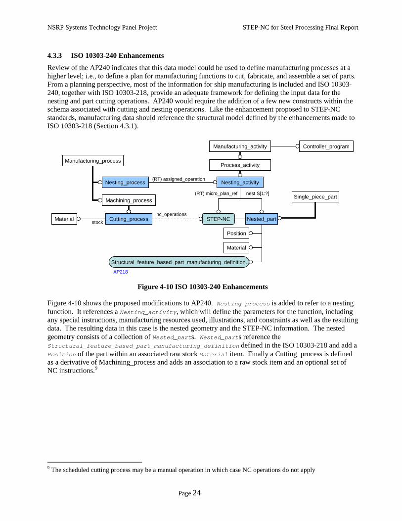
Figure 4-10 ISO 10303-240 Enhancements
Figure 4-10 shows the proposed modifications to AP240. Nesting_process is added to refer to a nesting function. It references a Nesting_activity, which will define the parameters for the function, including any special instructions, manufacturing resources used, illustrations, and constraints as well as the resulting data. The resulting data in this case is the nested geometry and the STEP-NC information. The nested geometry consists of a collection of Nested_parts. Nested_parts reference the Structural_feature_based_part_manufacturing_definition defined in the ISO 10303-218 and add a Position of the part within an associated raw stock Material item. Finally a Cutting_process is defined as a derivative of Machining_process and adds an association to a raw stock item and an optional set of NC instructions.9
9 The scheduled cutting process may be a manual operation in which case NC operations do not apply
Controller_program
Manufacturing_process
Manufacturing_activity
Machining_process
Cutting_processCutting_processnc_operations
STEP-NC
Nesting_activity(RT) assigned_operation
nest S[1:?]
Nesting_process
Nested_part
Material
Position
Structural_feature_based_part_manufacturing_definition.
Material stock
AP218
Process_activity
(RT) micro_plan_ref Single_piece_part

NSRP Systems Technology Panel Project STEP-NC for Steel Processing Final Report
Page 25
5 A STEP-based Environment Whereas the previous section focused on a specific part of the shipbuilding lifecycle for manufacturing of structural parts, this section discusses the larger issue of incorporating STEP within an organization and proposes a data architecture defined using existing STEP protocols and a rules-based management system to provide and enforce context-specific requirements.
5.1 Application of Manufacturing Rules A significant benefit of adopting STEP standards is the freedom it provides to an organization to choose the STEP-enabled systems to deploy. Contrast that possibility with the current situation in which a choice of a particular CAD system predetermines the choice of CAM system, for example. Adoption of any standard alone, especially one as broad as STEP, will not sufficiently support an open architecture manufacturing system; one that can support unique manufacturing processes and tools along with specific yard capabilities and capacities. Although a standard will provide the framework for how data is organized, the types of information supported, the range of allowed values, and may include constraints on how the data can be used or interpreted, additional software and/or manual intervention is required to enforce manufacturing rules and ensure the manufacturing and/or processing requirements are being met. Today, much of the logic that defines and processes unique yard requirements is embedded in custom, purpose-built software applications or add-ons to COTS systems using vendor-specific APIs. This situation limits flexibility to incorporate new systems into an existing architecture.
Using the Nesting function as an example, manufacturing rules answer such questions as:
• How far away from the edge of a stock plate (and from one another) can parts be nested?
• What edges can be combined? • What types of markings are applied to
the plates? • What are the tab and lead in/out
parameters?
• How are parts nested – by unit or by stage?
• What side of a plate part should face up in a nest?
• What types of accuracy control are used?
Answers to these questions are implicitly defined within the data sets when the data is generated at its source and vary widely based on the environment, the processes in place at a yard, and the capabilities of the machinery being used. So, even though data may be encapsulated within a standard medium, its content may be useless when data from one environment is used in another. What is needed is an environment in which COTS products, with complete STEP import/export support, are employed to perform their core function only, leaving the application of yard-specific rules to a separate, and open, rules management framework. Such a system can be tailored by applying rule sets developed for a particular situation or environment.
In the early part of 2002, the National Shipbuilding Research Program (NSRP) sponsored phase 0 of the Integrated Steel Processing Environment (ISPE) project. Included in the team were members, within the manufacturing discipline, of four major US shipyards. This program reviewed current manufacturing functional and data requirements for each of these yards and proposed a common data architecture, based on STEP, and a concept of operations that laid the foundation for a rules-based system to perform the functions mentioned above. The program continued as part of the Integrated Shipbuilding Environment in 2004, in which a prototype Steel Processing application was developed. The Steel Processing utility application, although originally developed to address steel plate manufacturing, has at its core the ability to apply separately-defined rule sets to STEP data files to auto-generate and validate product model data with respect to yard-specific requirements. The ISPE software was developed to address product data

NSRP Systems Technology Panel Project STEP-NC for Steel Processing Final Report
Page 26
interoperability by providing a means to apply explicitly-defined process logic to standards-based product model data sets yielding product model data that can be readily used by downstream systems such as Nesting and CAM. The Steel Processing application or any other system that manages and applies manufacturing rules is one part of system that would enable the use of ‘pluggable’ software systems.
5.2 Central Data Repository Figure 5-1 is an environment in which all relevant STEP application protocols are used as the primary exchange specification between systems within common shipbuilding functions and a central data repository. This architecture, also known as an Integrated Data Environment (IDE), serves as an authoritative source for all information pertaining to shipbuilding from design through manufacturing and life cycle support.
Figure 5-1 Central Data Repository
The details of this type of architecture are beyond the scope of this document. There are several frameworks that exist, and that are in widespread use, that would adequately serve the needs of such an environment. Beyond that, implementing an environment such as the one proposed above will involve:
• Creating comprehensive interface specifications for each software function. These interface specifications would then need to be mapped to the current STEP protocols. These data schemas are, for the most part, already defined within various parts of the STEP standard and since these standards have been developed by various industry experts, they have their respective data requirements built in. However, STEP has been designed to be used primarily for point-to-point data transfer with individual protocols serving a specific domain. An effort is therefore required to integrate all the appropriate STEP specifications, similar to the manner proposed by this document, so they can be used together as a common database schema.
• Development of full STEP-based import/export functionality for existing design, manufacturing, and planning systems. This is a tall order seeing it involves the participation of multiple vendors,
Planning
ManufacturingEngineering
Nest Plates
Design
MaterialManagement
Shell PlateDevelopment
ManufacturingAids
PartsGeneration
GenerateWork Packages
ProductionControl
Design/MfgProduct Model(STEP-based)
203/215/216/218/227 240
203/215/216/218/227
203/216/218/227
203/216/218
203/216/218
218/238/240
218/227/238/240
240
Life CycleEngineering
233/239
240• material data• production activities• structural model• design model
Rules
IDE

NSRP Systems Technology Panel Project STEP-NC for Steel Processing Final Report
Page 27
and developing full support for this functionality will be limited to the capability of the each respective system. Also, it may not always be in the best interest of a COTS tool provider to provide this functionality.
• Designing a framework for the rules-based management system. There are two parts to this step: defining the structure for the rules definition, defining the system to process them. There are currently emerging standards for defining rules. These need to be examined for their relevance and applicability to the shipbuilding domain. There are also multiple rule-based frameworks in existence.
• Designing the data repository. A large ship can consist of millions of individual components. Each one of these is managed/tracked separately. When you factor in all of the supporting data and the information for describing assemblies of these components the information requirements are immense.
If the implementation of such a system is kept ‘open’, employing standard interfaces/implementations wherever possible, it will retain its ability to be deployed in any environment. Generating location-specific data artifacts (i.e., reports) since full/complete access to the data is provided. Work sharing at various levels, using STEP data extracts, is also enabled since the format of the data is standard, but the processing of manufacturing rules is left to each implementation.
NSRP Systems Technology Panel Project STEP-NC for Steel Processing Final Report
Page 28
6 Conclusion Although STEP-NC was not originally developed to support the manufacturing requirements for shipbuilding, its core structure is an adequate framework on which to support these requirements. This work reviewed the data requirements for Nesting and CNC operations, in the context of a typical shipbuilding manufacturing lifecycle, and proposed the use of two additional relevant STEP application protocol specifications to support these requirements. The coordinated use of these three schemas, which refer to a common feature-based definition of manufacturing data, provides a standards-based alternative to the interfaces used today. This use obviates the need for non-value added, vendor-specific post-processing functionality and provides a shipbuilding infrastructure with more flexibility in the choice of deployed systems. The document also submits that in order to provide an architecture that truly enables pluggable component systems, the processing of yard-specific rules must be centralized using explicitly defined manufacturing rule sets. This, coupled with a central data repository based on the existing STEP schemas, provides a consistent means of managing and accessing shipbuilding information.