Embed Size (px)
Citation preview
Document reference NSP/002 Document Type: Policy
Version:- 3.1 Date of Issue:- November 2016 Page 1 of 27
CAUTION! - This document may be out of date if printed
NSP/002 – Policy for the Installation of Distribution Power Cables
1. Purpose
The purpose of this document is to detail Northern Powergrid’s (the Company) policy for the installation of distribution power cables at all voltage levels (230V up to and including 132kV) for connection to the Company’s network. This policy also helps to attain the distribution business goal of being a leading safety performer within our industry sector.
All parties installing new underground distribution power cables and auxiliary cables for connection to the Company’s network shall follow the content of this document.
This policy shall be used as the primary source of information for the installation of distribution power cables. Guidance on elements of the installation of distribution power cables not covered within this policy shall be sought from other appropriate Company documentation.
This document supersedes the following documents, all copies of which should be destroyed.
Ref Version Date Title
NSP/002 2.0 Sept 2015 Policy for the Installation of Distribution Power Cables
2. Scope
This document applies to the installation of all distribution power cables. Distribution power cables are defined as those cables used directly for the transfer of electricity from the 132kV system through to the low voltage (LV) service at customers’ premises.
The document provides guidance and sets out the Company policy on the procedures that are to be followed when installing distribution power cables. The document covers the excavation of trenches, trench preparation, installation of ducts, installation of safety features and warning signs, laying and pulling in of cables, back filling of trenches, re-making of ground and recording of cable positions.
This document does not detail specific cable installation solutions but refers to such issues in general terms. Specific cable installations shall follow codes of practice and guidance documents where available alternatively they shall be developed on an individual basis and agreed with an appropriate Company representative. Details covering the specific requirements for power cables and their associated accessories including ducts, tile tape and other markers are provided by individual Network Product Specifications (NPS) in each case.
It also offers sources of information to Northern Powergrid, its contractor’s and Independent Connection Providers (ICP). It enables all of the different functions within the business and its contractors to make informed design, construction and operational decisions that will mitigate the risks associated with the installation of distribution power cables.
Document reference NSP/002 Document Type: Policy
Version:- 3.1 Date of Issue:- November 2016 Page 2 of 27
CAUTION! - This document may be out of date if printed
2.1 Table of Contents
1. Purpose .................................................................................................................................................................... 1
2. Scope ....................................................................................................................................................................... 1
2.1 Table of Contents ........................................................................................................................................................ 2
3. Policy ....................................................................................................................................................................... 4
3.1 Assessment of Relevant Drivers ................................................................................................................................. 4
3.2. Key Policy Requirements ............................................................................................................................................ 4
3.2.1. General ............................................................................................................................................................... 4
3.2.2. Fire Precautions .................................................................................................................................................. 5
3.2.3. Cables Routed in Communal Positions ............................................................................................................... 6
3.2.4. Route Planning ................................................................................................................................................... 6
3.2.5. Location of Cable Trenches ................................................................................................................................ 7
3.2.6. Depths of Cables ................................................................................................................................................. 7
3.2.7. Shallow Cables .................................................................................................................................................... 8
3.2.8. Exposed Cables ................................................................................................................................................. 10
3.2.9. Minimum Cable Spacing ................................................................................................................................... 10
3.2.10. Installation Medium and Positioning of Cables .............................................................................................. 11
3.2.11. Excavated Materials and Site Restrictions ...................................................................................................... 14
3.2.12. Cable Trenches ............................................................................................................................................... 14
3.2.13. Obstructions ................................................................................................................................................... 15
3.3. Trenchless Excavation ............................................................................................................................................ 15
3.3.1. General ....................................................................................................................................................... 15
3.3.2. Depth of guided boring / directional drills ................................................................................................ 16
3.3.3. Multiple Crossings ...................................................................................................................................... 16
3.3.4. Railway Crossings ....................................................................................................................................... 16
3.3.5. River and canal crossings ........................................................................................................................... 16
3.3.6. Protective Covers ....................................................................................................................................... 16
3.4. Pulling in Cables ..................................................................................................................................................... 16
3.4.1. General ....................................................................................................................................................... 16
3.4.2. Maximum Pulling Tensions ........................................................................................................................ 17
Document reference NSP/002 Document Type: Policy
Version:- 3.1 Date of Issue:- November 2016 Page 3 of 27
CAUTION! - This document may be out of date if printed
3.4.3. Cable Pulling Techniques ........................................................................................................................... 18
3.4.4. Bending Radius........................................................................................................................................... 18
3.4.5. Ambient Temperature ............................................................................................................................... 19
3.4.6. Cutting and Sealing Cables ......................................................................................................................... 20
3.4.7. Sealing of Cable Entries .............................................................................................................................. 20
3.5. Route and Joint Markers ........................................................................................................................................ 21
3.5.1. General ....................................................................................................................................................... 21
3.5.2. Installation ................................................................................................................................................. 21
3.5.3. Installation of Markers on Network Rail Property ..................................................................................... 21
3.5.4. Backfilling and Reinstatement ................................................................................................................... 22
3.5.5. Cables Installed on Bridges / Structures / Overhead Terminations ........................................................... 22
3.6. Earthing and Bonding............................................................................................................................................. 22
3.6.1. Earthing and Bonding of EHV and 132kV Cables........................................................................................ 22
3.6.2. Earthing and Bonding of LV and HV Cables ................................................................................................ 23
3.7. Testing and Commissioning of newly installed Underground Cables .................................................................... 23
4. References ............................................................................................................................................................. 24
4.1. External Documentation ........................................................................................................................................ 24
4.2. Internal documentation ......................................................................................................................................... 25
4.3. Amendments from Previous Version ..................................................................................................................... 25
5. Definitions ............................................................................................................................................................. 26
6. Authority for issue ................................................................................................................................................. 27
6.1. CDS Assurance ....................................................................................................................................................... 27
6.2. Author .................................................................................................................................................................... 27
6.3. Technical Assurance ............................................................................................................................................... 27
6.4. Approval ................................................................................................................................................................. 27
6.5. Authorisation ......................................................................................................................................................... 27

Document reference NSP/002 Document Type: Policy
Version:- 3.1 Date of Issue:- November 2016 Page 4 of 27
CAUTION! - This document may be out of date if printed
3. Policy
3.1. Assessment of Relevant Drivers
Northern Powergrid operates circa 58,500km of underground distribution power cable (excluding service cable) and installs, around, 720km of cable every year. This consists of 8km of 132kV, 65km of EHV, 302km of HV, 345km of LV and 23,450 underground services per year.
Berkshire Hathaway Energy (BHE) has made a commitment within its corporate goal statements to be a leading safety performer within our industry sector. In addition, this policy will make a positive contribution to the following business values:
Employee Commitment
Regulatory Integrity
Environmental Respect
The ‘Electricity Safety, Quality and Continuity Regulations 2002’ (ESQCR), Part IV, Underground Cables and Equipment, gives absolute requirements for general restrictions, protective screens and excavations and depths of underground cables. The supplementary Department for Business Enterprise & Regulatory Reform document, ’Guidance on the Electricity Safety, Quality and Continuity Regulations 2002’, gives further detailed guidance on the same absolute requirements.
3.2. Key Policy Requirements
The objectives of this policy are:
To ensure the general safety of the public, including third parties excavating in the vicinity of our power cables.
To prevent Northern Powergrid from having a major breach of legal compliance through incorrect installation of distribution power cables and their associated safety features.
To specify the requirements for the installation of distribution power cables for voltages up to and including 132kV.
To maximise the life of the underground cable system through ensuring the cable is installed using well proven techniques.
3.2.1. General
The following section describes general requirements for work carried out for the installation of distribution power cables.
Compliance with Policy
In terms of cable route planning and installation, this policy offers in every instance the preferred approach. It is understood that engineering difficulties may be encountered that result in the preferred approach not being practically or economically achievable. Where this situation arises, authorisation for any deviation from the preferred approach shall always be sought and agreed with the Northern Powergrid project / design manager at any point from initial design through to final works completion.
Excavation Work
All distribution cable excavation work carried out shall be in accordance with the Health and Safety Executive Guidance Note HS (G) 47 - ‘Avoiding Danger from Underground Services’.
Work which is undertaken on the public highway shall be done so in accordance with the ’New Roads and Street Work Act 1991’ (NRSWA) and, ’The Traffic Management Act 2004 Regulations’ and codes of practice.

Document reference NSP/002 Document Type: Policy
Version:- 3.1 Date of Issue:- November 2016 Page 5 of 27
CAUTION! - This document may be out of date if printed
Cable Laying
All 33kV cables and above shall be laid in accordance with the requirements of Energy Networks Association Technical Specification (ENA-TS) 09–2, ’Specification for the Supply, Delivery & Installation of Power Cables with Operating Voltages in the Range 33kV to 400kV and Associated Auxiliary Cables’ unless varied by this specification. Additionally all relevant cable laying activities shall comply with Engineering Recommendation (ER) C61 - ’Installation Bending Radii of 33kV and Higher Voltage Cables’ and Engineering Recommendation (ER) C55/5 – ’Insulated Sheath Power Cable Systems’.
All other cables including those not covered in (ER) C61 shall be laid in accordance with this policy.
Contractor Management
Any equipment used for cable installation work which is defined under the ’Lifting Operations and Lifting Equipment Regulations 1998’, shall be rated, tested, inspected and operated in accordance with the ’Lifting Plant and Equipment (Records of Test and Examination) Regulations 1992’.
The Contractor and his representatives shall fully comply with regulations issued by Network Rail, any relevant statutory bodies and in accordance with Northern Powergrid Safety Rules regarding electrical apparatus and the safety of men working thereon. In addition, the ’IEE Regulations on the Electrical Equipment for Buildings’ (BS 7671) shall be observed where applicable.
Cable Installation
Cable installation work will also be carried out in accordance with ’The Construction (Design and Management) Regulations 2015’ whenever they apply.
Record Management
Any persons (including ICP’s, IDNO’s and contractors) carrying out works on the company’s cable network shall ensure that all appropriate information is provided for all new cable installation positions/routes including cable details, duct arrangement, and/or joint markers. This information shall be passed to Information Management and where appropriate the Northern Powergrid responsible project manager and shall be recorded on the appropriate records within Northern Powergrid. This shall be in accordance with the Highway Authorities and Utilities Committee, ’Code of Practice for Recording of Underground Apparatus in Streets’, Nov 2002. Additionally, where engineering difficulties result in the installation of the cable results in a non-standard layout, previously agreed with the Northern Powergrid project manager, then this information shall also be recorded.
Environmental
All aspects of the cable lifecycle from design through to installation, operational life, decommissioning and removal (where appropriate) shall comply with ENV/001 – ’Policy for Environmental Management’ and all other relevant Company environmental standards.
Auxiliary Circuits
As part of any underground cable schemes (e.g. new installation, replacement or diversion) all associated pilot and telecommunications cables shall be considered for replacement as described in IMP/001/913 – ’Code of Practice for the Economic Development of the EHV System’ and IMP/001/914 – ’Code of Practice for the Economic Development of the 132kV System’.
3.2.2. Fire Precautions
All apparatus, connections and cable works shall be designed and arranged to minimise the risk of fire, and any damage which might be caused in the event of fire. Where relevant, all reasonable precautions shall be taken to comply with Energy Networks Association Engineering Recommendation (ENA-ER) S2/4 - ’Limitation of Fire Risk in Substations at 132kV and below and in Enclosed Cableways’ and ENA-TS 09-22 - ’Protection of Cable Installations Against the Effects of Fire’ and any other regulations as are applicable to the situation.

Document reference NSP/002 Document Type: Policy
Version:- 3.1 Date of Issue:- November 2016 Page 6 of 27
CAUTION! - This document may be out of date if printed
Where cables pass through a switch room floor into a basement or cable tunnel, precautions shall be taken to prevent:
The draining of oil from the switch room into the basement or tunnel.
The ingress of water or any noxious or explosive liquid or gas, into any enclosed space.
The slipping of cables, if burnt away from their cable boxes, into the basement or tunnel. To comply with these requirements, cables shall be clamped or suitably supported above, and immediately below, the switch room floor level.
3.2.3. Cables Routed in Communal Positions
Where service cables are installed in communal locations such as shopping centres, high rise flats, consideration shall be given to the following in order to minimise the risk of harm to the public and damage to other assets in that location:
Installations shall ensure that the cables are suitably physically protected to minimise the risk of damage from third parties.
The cables shall be suitably supported to minimise inadvertent movement or disturbance including during fault conditions.
The cables shall be suitably ‘marked’ / ‘labelled’ to ensure that persons working in the vicinity are aware of our cables.
The installation shall be suitably designed to minimise the risk of fire in accordance with section 0 - Fire Precautions.
Consideration shall be given to the ability to access the cable location for future replacement, maintenance and repair.
Consideration shall also be given to the level of access to the public from a site safety and security perspective.
3.2.4. Route Planning
Services
All new service cable installations shall be run only within the boundaries of the properties it supplies, i.e. a service to any one property shall not cross land belonging to another.
When replacing or re-locating existing cable assets, dedicated underground services as described above shall be provided where economically and physically practicable.
LV Mains
All new mains cables schemes up to and including 400V shall in the first instance be laid direct in a footpath and/or verge.
LV mains cables shall not be routed within the boundary of private properties and shall not be installed in footpaths at the rear of properties with only pedestrian access.
HV Mains
All new mains cables schemes up to and including 20kV shall in the first instance be laid direct in a footpath and/or verge.
33kV to 132kV Mains
Schemes at 33kV and above shall in the first instance be laid in suitable duct arrangements in the footpath and/or verge.
General Planning
All new cables shall in the first instance be laid in public land unless engineering difficulties dictate otherwise. In these circumstances, agreement shall be sought from the Northern Powergrid responsible project manager for alternate laying options.
Document reference NSP/002 Document Type: Policy
Version:- 3.1 Date of Issue:- November 2016 Page 7 of 27
CAUTION! - This document may be out of date if printed
Where it is necessary to lay any cables in private land then the route shall be secured by a permanent easement and meet the requirements of all Northern Powergrid wayleave policies. The route chosen shall not hinder future access for maintenance, repair, replacement or recovery of the cables.
When routing new cables, consideration shall be given to the potential for future network extension to cater for load development.
Where practicable the route shall avoid sections of exposed cable e.g. bridge crossings. If sections of exposed cables are unavoidable, they should have a level of protection suitable for the security risk at that site as detailed in section 3.2.8 – Exposed Cables.
Routes should ideally be simple, direct with minimal bends and the minimum of cross-over particularly in the open trench work of substations. Consideration shall also be given to minimising the volume of joints required as part of the installation. Where practical and economic, cables shall be laid on a route that is separate from other cables supplying or providing security to a given group of customers. Where cables are laid in proximity to existing cables or other heat sources, sufficient spacing should be allowed to prevent de-rating of either circuit. Where multiple cables enter a building (e.g. switchroom), where practicable these cables shall be laid direct to minimise the effect of mutual heating.
All measures shall be taken to avoid damage to other utilities and third party plant and equipment. All other statutory undertakers and the local authorities shall be contacted to determine the position and depth of their apparatus in the proposed route before any trial holes, excavation or trenchless installation is carried out.
Ground Penetrating Radar (GPR) surveys or hand dug trial holes may be necessary if information regarding a cable route is not readily available from Northern Powergrid or other undertakers’ plans. Trial holes shall be taken at proposed joint positions and at other positions along the route to determine the best practical position of the cable relative to the other services. This will also confirm the location of existing Northern Powergrid assets and other utilities along the proposed cable route.
Trial holes shall generally be at right angles to the route of the cable and at least 150mm deeper than the proposed trench. The number and size of the trial holes required will depend upon the congestion likely to be encountered and whether the trench is being hand or machine dug.
Further detail on route planning can be found in the following documentation:
IMP/001/911 –, Code of Practice for the Economic Development of Low Voltage Networks’.
IMP/001/912 – ’Code of Practice for the Economic Development of the HV System’.
IMP/001/913 – ’Code of Practice for the Economic Development of the EHV System’.
IMP/001/914 – ’Code of Practice for the Economic Development of the 132kV System’.
3.2.5. Location of Cable Trenches
Having decided upon the route the requisite clearances from other Utility equipment and Northern Powergrid cables shall be observed and trench depths maintained as detailed in section 3.2.6.
The exact location of each trench shall be approved on site. Cables shall be positioned, including their relation to other services, in accordance with the current National Joint Utilities Group (NJUG) guidance document, ‘NJUG Guidelines on the Positioning and Colour Coding of Underground Utilities’ Apparatus’
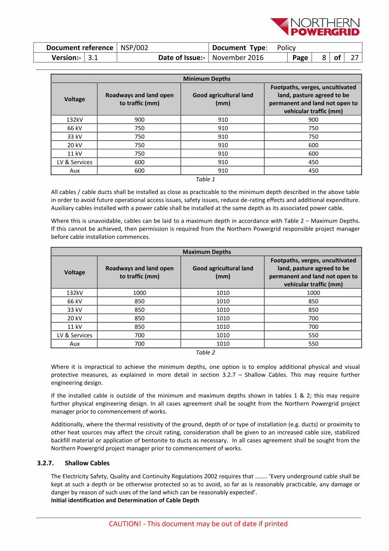
3.2.6. Depths of Cables
The minimum depths to the top of the uppermost cables or duct for the various laying conditions are shown in Table 1 – Minimum Depths:
Document reference NSP/002 Document Type: Policy
Version:- 3.1 Date of Issue:- November 2016 Page 8 of 27
CAUTION! - This document may be out of date if printed
Minimum Depths
Voltage Roadways and land open
to traffic (mm) Good agricultural land
(mm)
Footpaths, verges, uncultivated land, pasture agreed to be
permanent and land not open to vehicular traffic (mm)
132kV 900 910 900
66 kV 750 910 750
33 kV 750 910 750
20 kV 750 910 600
11 kV 750 910 600
LV & Services 600 910 450
Aux 600 910 450
Table 1
All cables / cable ducts shall be installed as close as practicable to the minimum depth described in the above table in order to avoid future operational access issues, safety issues, reduce de-rating effects and additional expenditure. Auxiliary cables installed with a power cable shall be installed at the same depth as its associated power cable.
Where this is unavoidable, cables can be laid to a maximum depth in accordance with Table 2 – Maximum Depths. If this cannot be achieved, then permission is required from the Northern Powergrid responsible project manager before cable installation commences.
Maximum Depths
Voltage Roadways and land open
to traffic (mm) Good agricultural land
(mm)
Footpaths, verges, uncultivated land, pasture agreed to be
permanent and land not open to vehicular traffic (mm)
132kV 1000 1010 1000
66 kV 850 1010 850
33 kV 850 1010 850
20 kV 850 1010 700
11 kV 850 1010 700
LV & Services 700 1010 550
Aux 700 1010 550
Table 2
Where it is impractical to achieve the minimum depths, one option is to employ additional physical and visual protective measures, as explained in more detail in section 3.2.7 – Shallow Cables. This may require further engineering design.
If the installed cable is outside of the minimum and maximum depths shown in tables 1 & 2; this may require further physical engineering design. In all cases agreement shall be sought from the Northern Powergrid project manager prior to commencement of works.
Additionally, where the thermal resistivity of the ground, depth of or type of installation (e.g. ducts) or proximity to other heat sources may affect the circuit rating, consideration shall be given to an increased cable size, stabilized backfill material or application of bentonite to ducts as necessary. In all cases agreement shall be sought from the Northern Powergrid project manager prior to commencement of works.
3.2.7. Shallow Cables
The Electricity Safety, Quality and Continuity Regulations 2002 requires that …….. ‘Every underground cable shall be kept at such a depth or be otherwise protected so as to avoid, so far as is reasonably practicable, any damage or danger by reason of such uses of the land which can be reasonably expected’. Initial identification and Determination of Cable Depth
Document reference NSP/002 Document Type: Policy
Version:- 3.1 Date of Issue:- November 2016 Page 9 of 27
CAUTION! - This document may be out of date if printed
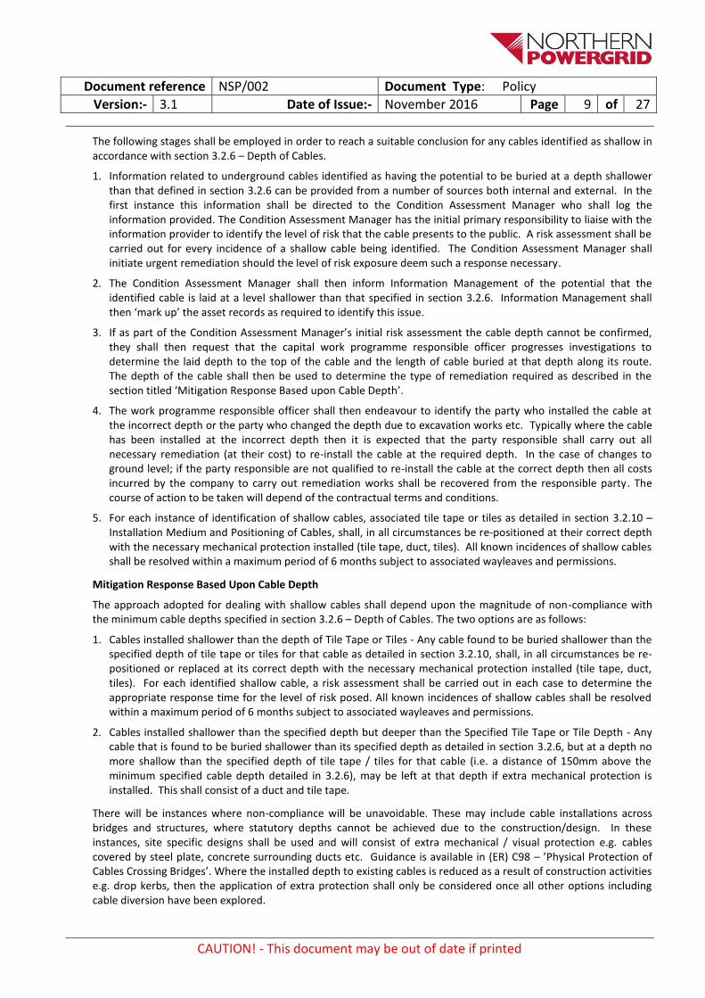
The following stages shall be employed in order to reach a suitable conclusion for any cables identified as shallow in accordance with section 3.2.6 – Depth of Cables.
1. Information related to underground cables identified as having the potential to be buried at a depth shallower than that defined in section 3.2.6 can be provided from a number of sources both internal and external. In the first instance this information shall be directed to the Condition Assessment Manager who shall log the information provided. The Condition Assessment Manager has the initial primary responsibility to liaise with the information provider to identify the level of risk that the cable presents to the public. A risk assessment shall be carried out for every incidence of a shallow cable being identified. The Condition Assessment Manager shall initiate urgent remediation should the level of risk exposure deem such a response necessary.
2. The Condition Assessment Manager shall then inform Information Management of the potential that the identified cable is laid at a level shallower than that specified in section 3.2.6. Information Management shall then ‘mark up’ the asset records as required to identify this issue.
3. If as part of the Condition Assessment Manager’s initial risk assessment the cable depth cannot be confirmed, they shall then request that the capital work programme responsible officer progresses investigations to determine the laid depth to the top of the cable and the length of cable buried at that depth along its route. The depth of the cable shall then be used to determine the type of remediation required as described in the section titled ‘Mitigation Response Based upon Cable Depth’.
4. The work programme responsible officer shall then endeavour to identify the party who installed the cable at the incorrect depth or the party who changed the depth due to excavation works etc. Typically where the cable has been installed at the incorrect depth then it is expected that the party responsible shall carry out all necessary remediation (at their cost) to re-install the cable at the required depth. In the case of changes to ground level; if the party responsible are not qualified to re-install the cable at the correct depth then all costs incurred by the company to carry out remediation works shall be recovered from the responsible party. The course of action to be taken will depend of the contractual terms and conditions.
5. For each instance of identification of shallow cables, associated tile tape or tiles as detailed in section 3.2.10 – Installation Medium and Positioning of Cables, shall, in all circumstances be re-positioned at their correct depth with the necessary mechanical protection installed (tile tape, duct, tiles). All known incidences of shallow cables shall be resolved within a maximum period of 6 months subject to associated wayleaves and permissions.
Mitigation Response Based Upon Cable Depth
The approach adopted for dealing with shallow cables shall depend upon the magnitude of non-compliance with the minimum cable depths specified in section 3.2.6 – Depth of Cables. The two options are as follows:
1. Cables installed shallower than the depth of Tile Tape or Tiles - Any cable found to be buried shallower than the specified depth of tile tape or tiles for that cable as detailed in section 3.2.10, shall, in all circumstances be re-positioned or replaced at its correct depth with the necessary mechanical protection installed (tile tape, duct, tiles). For each identified shallow cable, a risk assessment shall be carried out in each case to determine the appropriate response time for the level of risk posed. All known incidences of shallow cables shall be resolved within a maximum period of 6 months subject to associated wayleaves and permissions.
2. Cables installed shallower than the specified depth but deeper than the Specified Tile Tape or Tile Depth - Any cable that is found to be buried shallower than its specified depth as detailed in section 3.2.6, but at a depth no more shallow than the specified depth of tile tape / tiles for that cable (i.e. a distance of 150mm above the minimum specified cable depth detailed in 3.2.6), may be left at that depth if extra mechanical protection is installed. This shall consist of a duct and tile tape.
There will be instances where non-compliance will be unavoidable. These may include cable installations across bridges and structures, where statutory depths cannot be achieved due to the construction/design. In these instances, site specific designs shall be used and will consist of extra mechanical / visual protection e.g. cables covered by steel plate, concrete surrounding ducts etc. Guidance is available in (ER) C98 – ’Physical Protection of Cables Crossing Bridges’. Where the installed depth to existing cables is reduced as a result of construction activities e.g. drop kerbs, then the application of extra protection shall only be considered once all other options including cable diversion have been explored.
Document reference NSP/002 Document Type: Policy
Version:- 3.1 Date of Issue:- November 2016 Page 10 of 27
CAUTION! - This document may be out of date if printed
Any instance where a cable cannot be mechanically protected or diverted into a more secure position so far as reasonably practicable shall be disconnected from the live cable system until an appropriate solution has been employed.
3.2.8. Exposed Cables
When cables are exposed during the course of any works, they shall be suitably blinded or otherwise protected e.g. by portable security type fencing, blinding material as detailed in section 3.2.12 - Cable Trenches where practical and as soon as is reasonably practicable, to protect against interference / vandalism from third parties. Tile tape should also be applied above the cable to warn of the presence of a buried cable below should future ground work be undertaken over the cables. No underground cable may be left exposed and accessible to the public without justifiable cause supported by documentary evidence to show thorough consideration of the associated risks and the availability of appropriate control.
If the site is considered to be high risk e.g. adjacent to a school, public recreational area, housing estate or any other place where frequent public access occurs, then in all cases when the site is left unattended, the exposed cables shall be suitably blinded or otherwise protected.
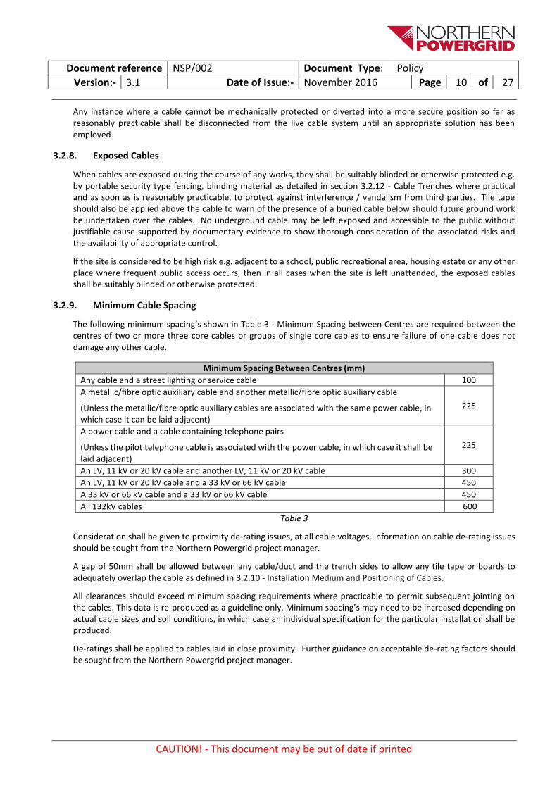
3.2.9. Minimum Cable Spacing
The following minimum spacing’s shown in Table 3 - Minimum Spacing between Centres are required between the centres of two or more three core cables or groups of single core cables to ensure failure of one cable does not damage any other cable.
Minimum Spacing Between Centres (mm)
Any cable and a street lighting or service cable 100
A metallic/fibre optic auxiliary cable and another metallic/fibre optic auxiliary cable
(Unless the metallic/fibre optic auxiliary cables are associated with the same power cable, in which case it can be laid adjacent)
225
A power cable and a cable containing telephone pairs
(Unless the pilot telephone cable is associated with the power cable, in which case it shall be laid adjacent)
225
An LV, 11 kV or 20 kV cable and another LV, 11 kV or 20 kV cable 300
An LV, 11 kV or 20 kV cable and a 33 kV or 66 kV cable 450
A 33 kV or 66 kV cable and a 33 kV or 66 kV cable 450
All 132kV cables 600
Table 3
Consideration shall be given to proximity de-rating issues, at all cable voltages. Information on cable de-rating issues should be sought from the Northern Powergrid project manager.
A gap of 50mm shall be allowed between any cable/duct and the trench sides to allow any tile tape or boards to adequately overlap the cable as defined in 3.2.10 - Installation Medium and Positioning of Cables.
All clearances should exceed minimum spacing requirements where practicable to permit subsequent jointing on the cables. This data is re-produced as a guideline only. Minimum spacing’s may need to be increased depending on actual cable sizes and soil conditions, in which case an individual specification for the particular installation shall be produced.
De-ratings shall be applied to cables laid in close proximity. Further guidance on acceptable de-rating factors should be sought from the Northern Powergrid project manager.
Document reference NSP/002 Document Type: Policy
Version:- 3.1 Date of Issue:- November 2016 Page 11 of 27
CAUTION! - This document may be out of date if printed
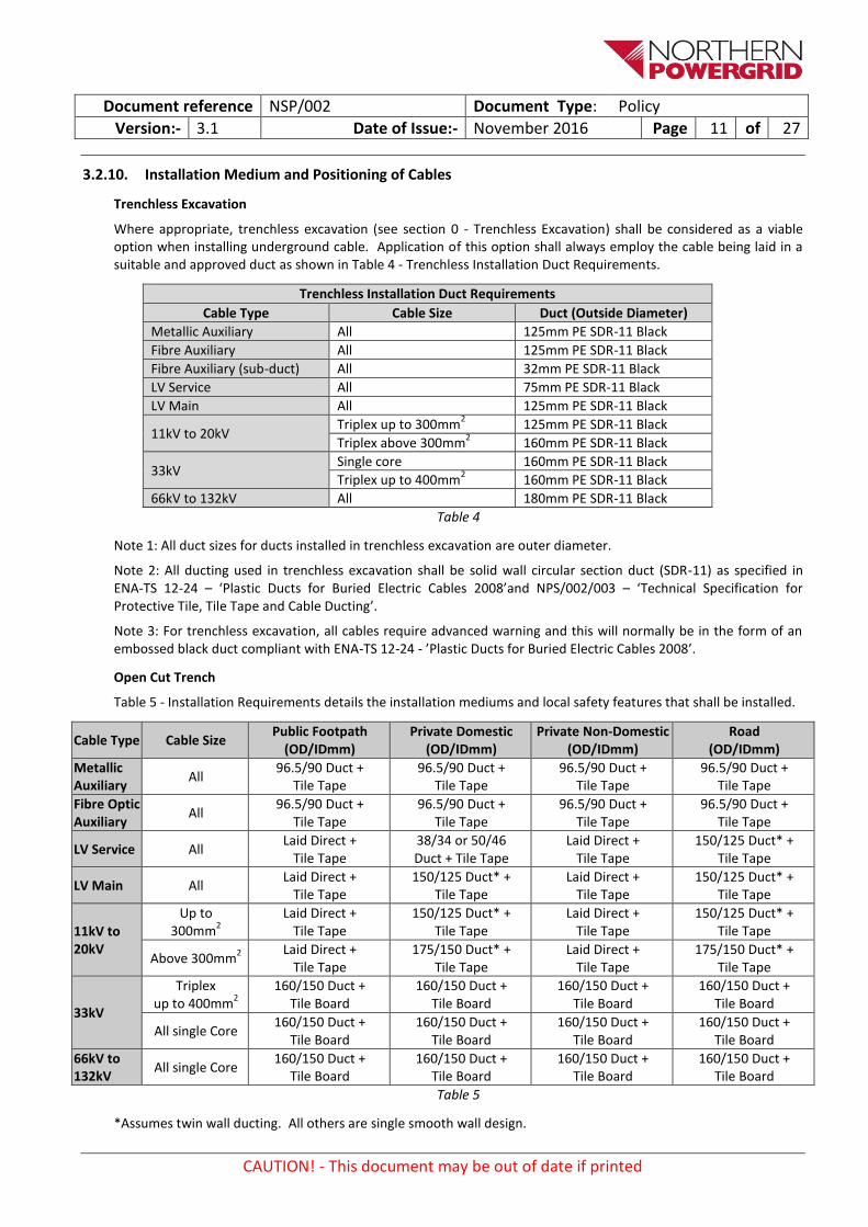
3.2.10. Installation Medium and Positioning of Cables
Trenchless Excavation
Where appropriate, trenchless excavation (see section 0 - Trenchless Excavation) shall be considered as a viable option when installing underground cable. Application of this option shall always employ the cable being laid in a suitable and approved duct as shown in Table 4 - Trenchless Installation Duct Requirements.
Trenchless Installation Duct Requirements
Cable Type Cable Size Duct (Outside Diameter)
Metallic Auxiliary All 125mm PE SDR-11 Black
Fibre Auxiliary All 125mm PE SDR-11 Black
Fibre Auxiliary (sub-duct) All 32mm PE SDR-11 Black
LV Service All 75mm PE SDR-11 Black
LV Main All 125mm PE SDR-11 Black
11kV to 20kV Triplex up to 300mm
2 125mm PE SDR-11 Black
Triplex above 300mm2 160mm PE SDR-11 Black
33kV Single core 160mm PE SDR-11 Black
Triplex up to 400mm2 160mm PE SDR-11 Black
66kV to 132kV All 180mm PE SDR-11 Black
Table 4
Note 1: All duct sizes for ducts installed in trenchless excavation are outer diameter.
Note 2: All ducting used in trenchless excavation shall be solid wall circular section duct (SDR-11) as specified in ENA-TS 12-24 – ‘Plastic Ducts for Buried Electric Cables 2008’and NPS/002/003 – ‘Technical Specification for Protective Tile, Tile Tape and Cable Ducting’.
Note 3: For trenchless excavation, all cables require advanced warning and this will normally be in the form of an embossed black duct compliant with ENA-TS 12-24 - ’Plastic Ducts for Buried Electric Cables 2008’.
Open Cut Trench
Table 5 - Installation Requirements details the installation mediums and local safety features that shall be installed.
Cable Type Cable Size Public Footpath
(OD/IDmm) Private Domestic
(OD/IDmm) Private Non-Domestic
(OD/IDmm) Road
(OD/IDmm)
Metallic Auxiliary
All 96.5/90 Duct +
Tile Tape 96.5/90 Duct +
Tile Tape 96.5/90 Duct +
Tile Tape 96.5/90 Duct +
Tile Tape
Fibre Optic Auxiliary
All 96.5/90 Duct +
Tile Tape 96.5/90 Duct +
Tile Tape 96.5/90 Duct +
Tile Tape 96.5/90 Duct +
Tile Tape
LV Service All Laid Direct +
Tile Tape 38/34 or 50/46 Duct + Tile Tape
Laid Direct + Tile Tape
150/125 Duct* + Tile Tape
LV Main All Laid Direct +
Tile Tape 150/125 Duct* +
Tile Tape Laid Direct +
Tile Tape 150/125 Duct* +
Tile Tape
11kV to 20kV
Up to 300mm
2
Laid Direct + Tile Tape
150/125 Duct* + Tile Tape
Laid Direct + Tile Tape
150/125 Duct* + Tile Tape
Above 300mm2
Laid Direct + Tile Tape
175/150 Duct* + Tile Tape
Laid Direct + Tile Tape
175/150 Duct* + Tile Tape
33kV
Triplex up to 400mm
2
160/150 Duct + Tile Board
160/150 Duct + Tile Board
160/150 Duct + Tile Board
160/150 Duct + Tile Board
All single Core 160/150 Duct +
Tile Board 160/150 Duct +
Tile Board 160/150 Duct +
Tile Board 160/150 Duct +
Tile Board
66kV to 132kV
All single Core 160/150 Duct +
Tile Board 160/150 Duct +
Tile Board 160/150 Duct +
Tile Board 160/150 Duct +
Tile Board
Table 5
*Assumes twin wall ducting. All others are single smooth wall design.

Document reference NSP/002 Document Type: Policy
Version:- 3.1 Date of Issue:- November 2016 Page 12 of 27
CAUTION! - This document may be out of date if printed
Note 1: All sizes for ducts installed in open trenches are nominal diameter measurement.
Note 2: All new cable installations shall have tile tape or tile board installed above the cables / ducts.
At all voltages tile tape and/or tile boards shall be installed to ensure an overlap of 50mm either side of the cable(s)/duct(s).
In order to effectively deliver this, tile tape is supplied in various widths as detailed in NPS/002/003 – ‘Technical Specification for Protective Tile, Tile Tape and Cable Ducting’. Where the correct width of tile is not available, then overlapping of the tile tape and/or tile boards is acceptable.
Note 3: Cables in the range 230V to 20 kV shall be laid under tile tape positioned 150mm directly above the top of the uppermost cable / duct.
Cables in the range 33kV to 132kV shall be laid under tile boards positioned 75mm directly above the top of the uppermost cable / duct. Each tile board shall be closely interlocked with adjacent covers throughout the length of the cable.
Note 4: Multiple metallic auxiliary cables may be installed in a single duct. However, metallic auxiliary cables associated with different power circuits must normally be installed in separate ducts to afford increased system security by reducing the risk of multiple cables suffering damage at a single location. Refer to NSP/002/005 – ‘Code of Practice for Cable Locations in Trench Layouts (Draft in development)’.
Note 5: Fibre Optic auxiliary ducts shall normally contain two Fibre Optic Sub-Ducts associated with a single power circuit only as per NSP/002/001 – ‘Guidance document for the installation of Fibre Optic Underground Cables’.
Note 6: All ducting used in open trench excavation shall be used as part of cable installation works shall be as specified in NPS/002/003 – ‘Technical Specification for Protective Tile, Tile Tape and Cable Ducting’.
Note 7: De-rating factors shall be considered and applied for ducted cable installations. Selection of duct dimensions shall also consider the number of installed cables, physical cable size, minimum bending radius, pulling tension and proposed pulling route.
Note 8: All cables shall be installed in the footpath/verge where possible. However this may not always be reasonably practicable, particularly at EHV when taking account of interference with or by other existing utilities equipment. If this cannot be avoided then the preferred option is to install the cable in ducts in the road with appropriate tile tape and/or tile boards, parallel to the footpath.
In some cases however, it may not be practical to install in ducts, for example: LV cables with many service connections, HV, EHV or 132kV cables that may have problems with de-rating factors due to duct installations. In such cases where the laid direct option is more suitable, cables shall always have the required tile tape / tile boards installed. Prior agreement to this option shall be sought from the Northern Powergrid project manager before commencement of works.
Note 9: Cables installed for future jointing to existing cables shall be adequately overlapped to allow easier jointing.
Note 10: Some residential developments are laid out as ‘Home Zones’, or similarly have a single thoroughfare dedicated to pedestrian, rather than vehicle, use. However, these thoroughfares are still highways and will experience vehicle traffic. In such areas, mains cables shall be laid in the 2m service margin within the thoroughfare provided by the developer. All cables passing through this service margin shall be installed to the standard required for a roadway: ducts are required only for road crossings etc.
This contrasts with ‘Design Bulletin 32’ (Residential Roads and Footpaths) estates, which have a conventional roadway but no footpath. Here, the developer provides a 2m service reserve to the side of the thoroughfare, generally in the gardens of the properties. In such areas, mains cables shall be laid within that reserve to the standard required for footpaths and verges (except where road crossings are required, in which case the relevant standard shall apply).
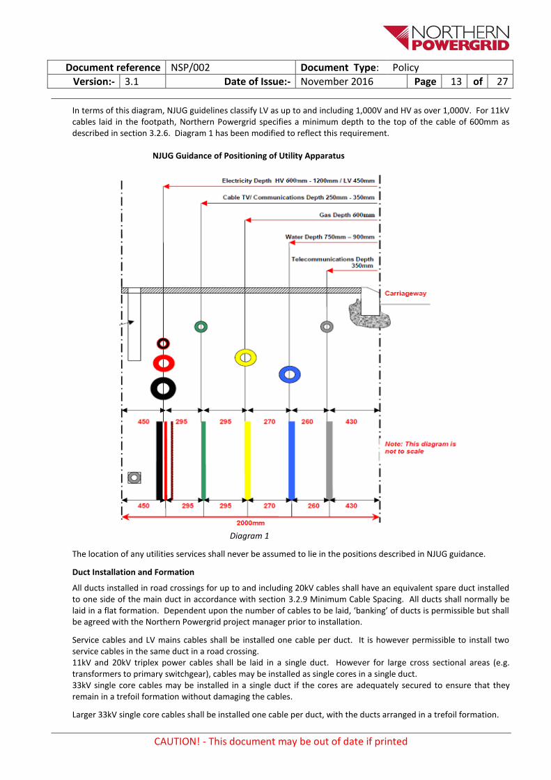
Diagram 1 - NJUG Guidance of Positioning of Utility Apparatus details the National Joint Utilities Group guidance (taken from ‘NJUG Guidelines on the Positioning and Colour Coding of Underground Utilities’ Apparatus’) on placement of distribution power cables (in addition to other utilities services) in a 2 metre wide footpath. The location of new Northern Powergrid power cables shall follow this guidance wherever possible, unless a greater depth is required under section 3.2.6.
Document reference NSP/002 Document Type: Policy
Version:- 3.1 Date of Issue:- November 2016 Page 13 of 27
CAUTION! - This document may be out of date if printed
In terms of this diagram, NJUG guidelines classify LV as up to and including 1,000V and HV as over 1,000V. For 11kV cables laid in the footpath, Northern Powergrid specifies a minimum depth to the top of the cable of 600mm as described in section 3.2.6. Diagram 1 has been modified to reflect this requirement.
NJUG Guidance of Positioning of Utility Apparatus
Diagram 1
The location of any utilities services shall never be assumed to lie in the positions described in NJUG guidance.
Duct Installation and Formation
All ducts installed in road crossings for up to and including 20kV cables shall have an equivalent spare duct installed to one side of the main duct in accordance with section 3.2.9 Minimum Cable Spacing. All ducts shall normally be laid in a flat formation. Dependent upon the number of cables to be laid, ‘banking’ of ducts is permissible but shall be agreed with the Northern Powergrid project manager prior to installation.
Service cables and LV mains cables shall be installed one cable per duct. It is however permissible to install two service cables in the same duct in a road crossing. 11kV and 20kV triplex power cables shall be laid in a single duct. However for large cross sectional areas (e.g. transformers to primary switchgear), cables may be installed as single cores in a single duct. 33kV single core cables may be installed in a single duct if the cores are adequately secured to ensure that they remain in a trefoil formation without damaging the cables.
Larger 33kV single core cables shall be installed one cable per duct, with the ducts arranged in a trefoil formation.

Document reference NSP/002 Document Type: Policy
Version:- 3.1 Date of Issue:- November 2016 Page 14 of 27
CAUTION! - This document may be out of date if printed
Spare ducts for power cables shall not be installed at 33kV and above unless specifically agreed with the Northern Powergrid project manager; however ducts for communications shall always be considered.
Ducts required for Northern Powergrid protection and telecommunication circuits shall normally be laid to the side of the power cable or attached to the trefoil group as detailed in NSP/002/005 – ‘Code of Practice for Cable Locations in Trench Layouts (Draft in development)’. The pilot cable shall be laid nearest to their associated power cable. In the case of fibre optic cables these ducts may be installed as part of the tre-foil group and are to be installed in accordance with NSP/002/001 – ‘Guidance document for the installation of Fibre Optic Underground Cables’.
Ducts installed for road crossings shall normally be installed at right angles to the kerb, will extend approximately 150 mm beyond the kerb foundation into the pavement or grass verge.
Ducts will be laid in such a manner to avoid any permanent obstructions located within one metre of the duct ends.
A draw rope suitable for purpose shall be installed.
Immediately after installing, ducts must be rodded clean and sealed. Spare ducts should be filled with a wooden plug before sealing
If the ground is to be backfilled before the duct is used, the position of the duct ends shall be clearly marked with yellow marker paint.
3.2.11. Excavated Materials and Site Restrictions
Excavated material shall be placed so as to prevent unnecessary nuisance or damage to adjacent hedges, trees, ditches, drains, gateways, other property or contamination of adjacent finished surfaces. Excavated material shall be stacked a safe distance from the trench and in such a manner to avoid undue interference with traffic and to keep footways open wherever possible. Where, because of traffic or other considerations, excavated material cannot be retained on site, it shall be removed and returned later for backfilling ensuring no contamination with other materials has taken place throughout this process. The position of stockpiles of excavated materials or new materials shall be determined beforehand. All excavations in made ground shall be backfilled with imported backfill.
Where the obstruction due to site works will be such that it is considered necessary to close the road to traffic, an application shall be made to the street authority for a Temporary Traffic Regulation Order.
To facilitate the re-use, where appropriate, of excavated material for road foundations, the excavated road surface materials and base foundations shall be separately stacked from the excavated sub-soils. Turf, chippings and the like shall be removed over a predetermined width on either side, or on both sides, of the trench to reduce the possibility of damage and/or contamination to those surfaces adjacent to the trench line. When the cable trench is routed through property other than public roads or pathways, the appropriate conditions will be agreed with the owner and occupier.
3.2.12. Cable Trenches
Trenches shall be kept as straight as possible and each trench shall be excavated to the dimensions which will be sufficient to allow cables to be installed at the depth and spacing specified in sections 3.2.6 and 3.2.9 including the installation of tile tape/boards as specified in section 3.2.10. The trenches shall have vertical sides which shall be timbered, sheet piled or trench sheeted where necessary so as to avoid subsidence and damage or possible injury. The contractor shall take all reasonable precautions to prevent damage to the highway or ground surface from a slip or breaking away of the side of the trench. Excavation and filling in shall be so executed that all underground assets including but not limited to railways, tramways, walls, roads, sewers, drains, pipes, cables, tree roots, structures shall be reasonably secure against risk of subsidence or injury. The works shall be carried out to the satisfaction of the Authorities concerned. The provisions of BS6031 – ‘Code of Practice for Earthworks’ shall be carried out as far as is applicable.
All precautions shall be taken to minimise environmental impact when excavating in the vicinity of trees, bushes and hedgerows as discussed in EOC/17 – ‘Protection of Plants, Animals and Conservation Areas’.
Document reference NSP/002 Document Type: Policy
Version:- 3.1 Date of Issue:- November 2016 Page 15 of 27
CAUTION! - This document may be out of date if printed
Where a change of level is necessary, the bottom of the trench shall rise or fall gradually; there shall never be any step changes in the bottom level of a trench.
The contractor shall deal with and dispose of water so as to prevent any risk of the cable and other materials to be laid in the trenches being detrimentally affected. He shall provide pumps and appliances required and shall carry out the necessary pumping and bailing in a safe, clean and environmentally friendly manner.
LV, 11kV and 20kV cables may only be laid on the bottom of the trench when it is smooth and free from loose or projecting stones, rubble, rock etc. Where these conditions do not apply, an additional 75mm depth shall be excavated and replaced with an appropriate smooth bedding (E.g. sand).
LV, 11kV and 20kV cables shall be blinded with stone free soil, selected sand or limestone dust to a level of 75mm above the top of the uppermost cable/duct. The blinding material shall be hand rammed over and around the cables. Mechanical rammers must not be used for this purpose.
All 132kV, 66kV and 33kV cables shall be laid on a 75mm bed of selected sand / cement bound sand (CBS), and after laying be blinded with selected sand / CBS to a depth of 75mm above the top of the uppermost cable/duct. Arrangement drawings showing the cable trench configuration shall be provided for EHV cable installations.
Cable/duct surround material (e.g. selected sand, CBS) shall be as specified in section 3.5.4 - Backfilling and Reinstatement.
Unless otherwise agreed, provision shall be made during the excavation and until reinstatement, for reasonable access of persons and vehicles to properties or places adjacent to the route of excavation. All crossing boards and gangways shall be of adequate strength for their purpose and, where appropriate, shall be secured together in such a manner as to reduce the risk of accidental displacement.
Consideration shall be given to the safety of staff working on site when carrying out excavation activities with regard to ease of access and egress form excavations as deemed appropriate.
NSP/002/005 – ‘Code of Practice Detailing Cable Arrangements within Trench Layouts at all Voltages’ provides additional guidance.
3.2.13. Obstructions
When obstructions due to third party plant or assets are encountered, or alterations to buildings or foundations are required, or a special form of trench is necessary, or natural obstructions such as tree roots are encountered, the Northern Powergrid project manager shall determine the required action. All associated records should be updated to identify all obstructions encountered at site.
3.3. Trenchless Excavation
3.3.1. General
Northern Powergrid encourages the use of trenchless technology wherever cost effective and practicable. Trenchless technology shall only be used where a duct can be pulled in behind. Cables shall not be laid direct when using trenchless methods.
Northern Powergrid accepts the use of guided boring for short and direct LV and HV installations only. All other trenchless installations shall utilize Horizontal Directional Drilling (HDD) or Auger Bore techniques.
Before commencing trenchless excavation, all obstacles shall be identified. All measures shall be taken to avoid damage to all utilities’ and other third parties’ plant and equipment.
Where ducts are required to be fusion jointed, this shall be carried out to manufacturer specification unless otherwise stated by Northern Powergrid, the ducts must be de-beaded as appropriate to ensure a smooth inner surface (Electro-fusion should not result in internal bead formation).
All directional drills shall be operated by trained competent staff in accordance with the guidelines of UKSTT (UK Society for Trenchless Technology), industry standard procedures and best working practises.

Document reference NSP/002 Document Type: Policy
Version:- 3.1 Date of Issue:- November 2016 Page 16 of 27
CAUTION! - This document may be out of date if printed
Operatives are required to record by surface marking and/or marking plans to log the position of the line of the bore every 5m and the depth every 15m. More frequent measurements may be required for any significant changes in direction. All this information shall be freely made available to Northern Powergrid for mains record purposes.
The contractor shall be able to meet any special criteria specified by a third party, e.g. Network Rail, Environment Agency, drainage boards, Canal and River Trust and local authorities. This would normally include detailed engineering designs, method statements and site specific risk assessments.
3.3.2. Depth of guided boring / directional drills
The minimum and maximum cable depths as detailed in section 3.2.6 shall be observed. In some circumstances it may be necessary to install the ducts deeper. However, the additional depth shall be kept to a minimum, whilst adhering to the requirements of any third parties, to avoid de-rating the cable and ensure the cable is readily accessible for jointing. Whilst parts of the installation may be deeper (assuming this has been agreed with the Northern Powergrid project manager), the ends of the ducts start and finish at the standard installation depths.
3.3.3. Multiple Crossings
A minimum distance of 0.6m shall be maintained between bores for most installations, for 33kV up to 132kV the minimum distance is 3m. Each bore shall be ducted before commencing another crossing as the high compression force involved during boring may cause previous bores to collapse.
3.3.4. Railway Crossings
Railway crossings are subject to the engineering and wayleave requirements of the rail operator whose advice must be sought at an early stage.
3.3.5. River and canal crossings
River and canal crossings are subject to the engineering and wayleave requirements of the Canal & River Trust and Environment Agency (EA) whose advice must be sought at an early stage.
3.3.6. Protective Covers
Under no circumstances shall any cables be laid direct using trenchless technology.
All pipes and ducts shall be installed in an approved manner as agreed with the Northern Powergrid project manager.
All ducts for trenchless excavation by guided systems shall be black SDR 11 design (see table 4, section 3.2.10), suitably embossed with a warning of the presence of an Electric Cable and comply with ENA-TS 12-24 – ‘Plastic Ducts for Buried Electric Cables, 2008’ and current Northern Powergrid Standards document, NPS/002/003 – ‘Technical Specification for Protective Tile, Tile Tape and Cable Ducting’.
3.4. Pulling in Cables
3.4.1. General
The contractor shall give the Northern Powergrid project manager reasonable notice when cable laying is about to commence. Laying of cables shall not be started until the contractor has obtained the Northern Powergrid project manager’s sanction to proceed with the work. Prior to installation the cable shall be checked to ensure the ends are sealed, the cable is undamaged and the correct cable for the project.
Cables shall be installed in accordance with ENA-TS 09-2 – ‘The Specification for the Supply, Delivery and Installation of Power Cables with operating voltages on the range 33kV to 400kV and associated auxiliary cables’ and in accordance with the cable manufacturer’s recommendations.

Document reference NSP/002 Document Type: Policy
Version:- 3.1 Date of Issue:- November 2016 Page 17 of 27
CAUTION! - This document may be out of date if printed
Cables Laid Direct
Cables shall be laid either by hand or by winch. Whenever cables are hand or winch pulled, an adequate number of cable rollers shall be used to avoid cable damage. Cable rollers shall be arranged to support the cable during pulling in with special attention being paid at points where a change in trench direction takes place. On a straight length of cable trench, the cable rollers shall be placed at a maximum of 4 metres apart.
Cables Laid In Ducts
The cable shall always be pulled in line with the duct sockets, to prevent snagging of the cable sheath on the protruding lip. When re-entering a duct run, to create a joint bay, the ends of ducts shall be cleanly cut and smoothed, and rollers fitted where necessary to prevent damage of the cable sheath. A brush shall be drawn through the ducts to remove and dirt and debris. A wooden mandrel shall be drawn through the ducts to confirm ovality. Lubrication shall be applied to the duct and the cable(s) as deemed appropriate to reduce the pulling tension.
Both ends of the duct shall be uniquely marked prior to pulling in the cable to ensure correct identification of the cable ends.
3.4.2. Maximum Pulling Tensions
Table 6 - Maximum Pulling Tensions is re-produced as a guideline only. Guidance for specific manufacturer’s types of cable should be obtained from Policy and Standards section.
Maximum Pulling Tensions
Cable Type Size (sq. mm) Maximum Pulling
Tension (kg)
LV Waveform Cable
95 185 300
285 650 650
11kV PICAS 185 300
650 850
11, 20kV PILC 1c 300 Cu 500 Cu
2000 2000
11, 20kV PILSWA 3c 185 300
1650 2000
11/20kV XLPE 1c
300 Cu 400 Cu 500 Cu 630 Cu
1500 2000 2000 2000
11kV / 20kV Triplex 95 Al
185 Al 300 Al
850 1650 2000
33kV XLPE 1c
300 Cu 400 Cu 500 Al 630 Cu 630 Al 800 Al
1500 2000 1500 2000 2000 2000
66kV XLPE 1c 300 Cu 500 Cu
1500 2000
132kV XLPE 1c
400 Cu 630 Cu
1000 Cu 1200 Cu
2000 2000 2000 2000
Table 6

Document reference NSP/002 Document Type: Policy
Version:- 3.1 Date of Issue:- November 2016 Page 18 of 27
CAUTION! - This document may be out of date if printed
3.4.3. Cable Pulling Techniques
By Hand – On occasions there will be a need to pull in short lengths of cable by hand (e.g. fault repairs), where this applies it is permissible to use a correctly sized cable stocking fitted to the cable. Where deemed appropriate a second means of securing the cable shall be considered to prevent the stocking from becoming detached during cable installation.
By Winch – Cable pulling by winch shall only be carried out where there is a serviceable and accurate dynamometer calibrated in kgs. The maximum pulling force for any method of cable pulling shall not exceed the values shown in 3.4.2.
The winch rope shall be fitted with a swivel eye that must be in good working order and freely rotates to prevent the cable from twisting.
When pulling cables by mechanical winch, a load-limiting device must be used to ensure that the pulling tension applied to the cable does not exceed the maximum permissible tensions.
The pulling of cable by direct and unmonitored mechanical means (e.g. hitched to a vehicle, Land rover winch) is not permitted.
The method of connecting the winch to the cable is detailed in Table 7 - Winch to Cable Connection.
Winch to Cable Connection
Cable Connection Method
LV Waveform
11/20kV Triplex XLPE
11/20kV 1c XLPE
33kV 1c XLPE (up to 400mm2)
Connection to correctly sized cable stocking over roughened cable oversheath.
11kV PICAS Connection to correctly sized cable stocking over roughened cable oversheath (sheaths and cores to be drilled, pinned and sealed against moisture ingress).
11, 20kV PILC 3c Connection to correctly sized cable stocking (Assumes no PVC oversheath).
11kV/20kV PILC
33kV 1c XLPE (above 400mm2)
66kV/132kV 1c XLPE
Connection to conductor, sealed against moisture ingress.
Table 7
Special Circumstances – There may be occasions when special requirements dictate alternative means of pulling in cables (e.g. bond pulling). Where these are intended the maximum pulling tension shall not exceed the values shown in 3.4.2. If necessary, guidance should be obtained from Policy and Standards section.
Further detail can be found in the following documentation:
ENA-ER C.82 – ‘Pulling in 11kV Aluminium Sheathed, Consac and Waveform Cables’.
ENA-TS 09-2 – ‘The Specification for the Supply, Delivery and Installation of Power Cables with operating voltages on the range 33kV to 400kV and associated auxiliary cables’.
3.4.4. Bending Radius
No cable shall be bent to a radius smaller than that given by Table 8 - Minimum Bending Radius. Cables can be permanently damaged by over bending and the following minimum radii must be observed during and after installation. Wherever possible, larger installation radii should be used.
This data is re-produced as a guideline only. Guidance for specific manufacturer’s types of cable should be obtained from the manufacturer’s data sheet for the particular cable or the Policy and Standards Section.

Document reference NSP/002 Document Type: Policy
Version:- 3.1 Date of Issue:- November 2016 Page 19 of 27
CAUTION! - This document may be out of date if printed
Further detail can be found in the following documentation, Engineering Recommendation (ER) C61 – ‘Installation Bending Radii of 33kV and Higher Voltage Cables’.
Minimum Bending Radius
Cable Type and Voltage Size sq. mm Minimum Bending
Radius (mm)
LV – Service (Plastic Types)
All Single Phase CNE All Single Phase SNE
Three Phase CNE
125 150 250
LV Waveform (3-core) 95 120 185 300
550 600 700 850
LV Waveform (4-core) 95 185 300
600 800
1000
11 kV PICAS 95 185 300
600 750 900
20 kV PILC All Sizes 1200
XLPE single core 11kV 300 400 630
800 880
1040
XLPE single core 20kV 400 1060
Triplex 11 kV 95 185 300
880 1020 1170
Triplex 20 kV 95 185
1030 1170
XLPE 1c 33kV 300 400 630
995 1070 1220
XLPE 1c 66kV & 132kV with solid metallic sheath:- (“D” is the diameter of the cable and should be taken from the manufacturer’s datasheet or measurement of the cable) - Adjacent Joints & Terminations - Laid Direct - Pulled into Ducts
All Sizes
20D 30D 35D
Table 8
3.4.5. Ambient Temperature
Cables can be permanently damaged by being moved at low temperatures. Cable laying shall take place only when the ambient temperature is at or above 0°C and has been at this temperature for the previous 24 hours or special precautions have been taken to maintain the cables above this temperature to avoid the risk of damage during handling.
Document reference NSP/002 Document Type: Policy
Version:- 3.1 Date of Issue:- November 2016 Page 20 of 27
CAUTION! - This document may be out of date if printed
3.4.6. Cutting and Sealing Cables
Where a cable is to be cut, a clean cut shall be made at right angles to the axis of the cable. Each cable end shall be sealed by the application of a suitable end cap.
All cables up to and including 33kV installed on the Company’s behalf shall be fitted with company approved earthed cap ends, unless the cable is to be jointed before any backfilling of the cable route has taken place. The presence of an earthed cap end, indicated by the green oversheath, is an indication to assist with correct cable identification, but in the case of LV cables it is necessary to open the cable as if live, as specified in Distribution Safety Rule 8.3.1(b).
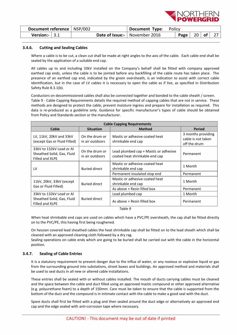
Conductors on decommissioned cables shall also be connected together and bonded to the cable sheath / screen. Table 9 - Cable Capping Requirements details the required method of capping cables that are not in service. These methods are designed to protect the cable, prevent moisture ingress and prepare for installation as required. This data is re-produced as a guideline only. Guidance for specific manufacturer’s types of cable should be obtained from Policy and Standards section or the manufacturer.
Cable Capping Requirements
Cable Situation Method Period
LV, 11kV, 20kV and 33kV (except Gas or Fluid Filled)
On the drum or in air outdoors
Mastic or adhesive coated heat shrinkable end cap
3 months providing cable is not taken off the drum
33kV to 132kV Lead or Al Sheathed Solid, Gas, Fluid Filled and XLPE
On the drum or in air outdoors
Lead plumbed cap + Mastic or adhesive coated heat shrinkable end cap
Permanent
LV Buried direct
Mastic or adhesive coated heat shrinkable end cap
1 Month
Permanent insulated stop end Permanent
11kV, 20kV, 33kV (except Gas or Fluid Filled)
Buried direct
Mastic or adhesive coated heat shrinkable end cap
1 Month
As above + Resin filled box Permanent
33kV to 132kV Lead or Al Sheathed Solid, Gas, Fluid Filled and XLPE
Buried direct Lead plumbed cap 1 Month
As above + Resin filled box Permanent
Table 9
When heat shrinkable end caps are used on cables which have a PVC/PE oversheath, the cap shall be fitted directly on to the PVC/PE, this having first being roughened.
On hessian covered lead sheathed cables the heat shrinkable cap shall be fitted on to the lead sheath which shall be cleaned with an approved cleaning cloth followed by a dry rag. Sealing operations on cable ends which are going to be buried shall be carried out with the cable in the horizontal position.
3.4.7. Sealing of Cable Entries
It is a statutory requirement to prevent danger due to the influx of water, or any noxious or explosive liquid or gas from the surrounding ground into substations, street boxes and buildings. An approved method and materials shall be used to seal ducts in all new or altered cable installations.
These entries shall be sealed with or without cables installed. The mouth of ducts carrying cables must be cleaned and the space between the cable and duct filled using an approved mastic compound or other approved alternative (e.g. polyurethane foam) to a depth of 150mm. Care must be taken to ensure that the cable is supported from the bottom of the duct and the compound is in intimate contact with the cable to make a good seal with the duct.
Spare ducts shall first be fitted with a plug and then sealed around the duct edge or alternatively an approved end cap and the edge sealed with anti-corrosion tape where necessary.
Document reference NSP/002 Document Type: Policy
Version:- 3.1 Date of Issue:- November 2016 Page 21 of 27
CAUTION! - This document may be out of date if printed
To further reduce the possibility of gas entering a building, sub-station, street box etc. where continuous ducting is laid, a break shall be provided in the duct run, if possible, immediately outside the building or equipment.
All cable ducts entering substations or buildings shall be sealed by products assessed by Northern Powergrid and installed in accordance with the manufacturer’s instructions to prevent the ingress of gas and water and generally in accordance with ENA-ER G17/3 – ‘Leakage of Flammable Gases’.
3.5. Route and Joint Markers
3.5.1. General
Cable route markers shall be used for indicating the route of cables on public or private property where difficulty might be experienced in locating the cables due to the absence of permanent landmarks and as an indication of the presence of electric cables where it is considered in the interests of safety that a warning should be given or where it has been agreed with another Authority that markers will be provided. Specifically, cable route markers shall be installed where cables traverse the following locations:
Motorways
Bridges
Waterways
Railways
For all new cable installations including service cable, marker posts will be erected in accordance with ENA-ER G.57 – ‘Cable Laying on Agricultural Land’ to indicate the precise route of all new cables laid on good agricultural land.
Cable joint markers will generally be used for the location of cable joints only where the absence of permanent landmarks would otherwise make it difficult to identify the position from mains records. They shall normally be used where the joints are on generating stations and substation sites and where it has been agreed to provide them at the request of other Authorities. In addition, marker blocks may be used in situations where vehicular movement may be impeded by the use of marker posts.
Directional drill markers should be used, where appropriate, at entry and exit points to positively identify the start and finish of directional drills, for example when crossing the following:
Motorways
Waterways
Railways
All markers shall be recorded on the Company’s records systems.
3.5.2. Installation
The cable route and joint markers shall be in accordance with Northern Powergrid specification NPS/002/003 – ‘Technical Specification for Protective Tile, Tile Tape and Cable Ducting’.
Cable route markers will normally be erected with the post buried in the ground half its height and will be placed as near as possible on the route of the cable but set back against adjacent walls or fences to avoid obstruction wherever possible.
Cable joint markers will normally be erected with the post buried in the ground half its height but where this would cause undue obstruction and there is no likelihood of its being buried or overgrown the post may be buried with only 300mm exposed. The marker shall be placed immediately opposite the centre of the joint in such a position that no obstruction is caused. The distance between the marker, the joint and the nearest permanent landmark shall be shown on the records.
3.5.3. Installation of Markers on Network Rail Property
When cables are laid on Rail Property, cable and joint markers shall be installed of the types approved by Network Rail.

Document reference NSP/002 Document Type: Policy
Version:- 3.1 Date of Issue:- November 2016 Page 22 of 27
CAUTION! - This document may be out of date if printed
Concrete cable route marker blocks approved by Network Rail shall be laid over the route of the cable at intervals to be agreed and at each change of direction. Where it is required to denote the position where Northern Powergrid cables cross railway tracks, a plastic coated aluminium plate shall be bolted to a marker post approved by the rail operator. The line between the posts shall indicate the line of the cable crossing.
Guidance for access to Network Rail Infrastructure is provided in NSP/005/001 – ‘Access Arrangements to Network Rail Infrastructure’.
3.5.4. Backfilling and Reinstatement
Unless otherwise specified all reinstatements, materials and plant shall meet the requirements of the New Roads and Street Works Act Specification for the Reinstatement of Openings in Highways. Where special backfill is required for cable/duct surround, this shall be in accordance with ENATS 97-1 – ‘Special Backfill Materials for Cable Installations’. The use of foamed concrete will be considered in special circumstances and by agreement with the Northern Powergrid project manager. The density of the foamed concrete if required shall be agreed with the Northern Powergrid project manager.
3.5.5. Cables Installed on Bridges / Structures / Overhead Terminations
When carrying out the installation of new or replacing existing cables, fixing to the exterior of bridges and structures (e.g. cable trays) shall be avoided where possible while taking account of all safety, operational and financial implications. Potential solutions include cable ducts which are suitably mechanically protected such as SDR11 as used in trenchless excavations and contained within the body of the structure or cable diversion as required.
If connection to the exterior of the structure cannot be avoided, then the installation shall be protected to a suitable standard to guard against 3rd party interference. In addition signing should be applied to warn other workers of the presence of cables in such a manner so as to not outwardly attract vandals/interference.
Further guidance can be found in NSP/002/010 – ‘Guidance on the physical protection of cables crossing bridges EREC C98’. When terminating cables on overhead structures such as terminal poles or substation busbars, cleating arrangements shall be applied to ensure that they:
Adequately support the weight of the cable,
Minimise cable movement,
Withstand the physical impact of cable short circuit currents.
Before the cable is terminated it shall stand in situ for and adequate period of time to allow for any initial ‘settling’ to take place. Cables must be cleated into position before any termination works are commenced.
Cleating arrangements shall be agreed with the Northern Powergrid project manager prior to the commencement of any works.
3.6. Earthing and Bonding
3.6.1. Earthing and Bonding of EHV and 132kV Cables
The earthing and bonding of cables, 33kV up to and including 132kV shall be in accordance with the requirements of ENA-ER C55-5 – ‘Insulated Sheath Power Cable Systems’.
In both cases manufacturer’s recommendations may be considered providing they do not contradict this document.
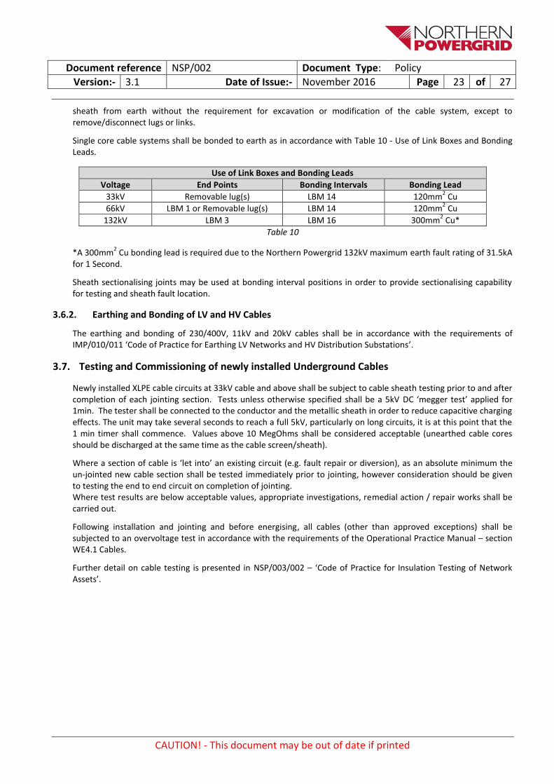
All 33kV, 66kV and 132kV cable systems shall be solidly bonded to earth at both ends as per Section 4.3 ‘Solidly Bonded Systems’ of ENA ER C55-5 – ‘Insulated Sheath Power Cable Systems’. In addition; all cable systems shall be bonded to earth at suitable ‘bonding intervals’ in order to prevent damage to the outer sheath due to high internal sheath voltages during a fault. All bonding at 33kV, 66kV and 132kV shall provide for the disconnection of the
Document reference NSP/002 Document Type: Policy
Version:- 3.1 Date of Issue:- November 2016 Page 23 of 27
CAUTION! - This document may be out of date if printed
sheath from earth without the requirement for excavation or modification of the cable system, except to remove/disconnect lugs or links.
Single core cable systems shall be bonded to earth as in accordance with Table 10 - Use of Link Boxes and Bonding Leads.
Use of Link Boxes and Bonding Leads
Voltage End Points Bonding Intervals Bonding Lead
33kV Removable lug(s) LBM 14 120mm2 Cu
66kV LBM 1 or Removable lug(s) LBM 14 120mm2 Cu
132kV LBM 3 LBM 16 300mm2 Cu*
Table 10
*A 300mm2 Cu bonding lead is required due to the Northern Powergrid 132kV maximum earth fault rating of 31.5kA
for 1 Second.
Sheath sectionalising joints may be used at bonding interval positions in order to provide sectionalising capability for testing and sheath fault location.
3.6.2. Earthing and Bonding of LV and HV Cables
The earthing and bonding of 230/400V, 11kV and 20kV cables shall be in accordance with the requirements of IMP/010/011 ‘Code of Practice for Earthing LV Networks and HV Distribution Substations’.
3.7. Testing and Commissioning of newly installed Underground Cables
Newly installed XLPE cable circuits at 33kV cable and above shall be subject to cable sheath testing prior to and after completion of each jointing section. Tests unless otherwise specified shall be a 5kV DC ‘megger test’ applied for 1min. The tester shall be connected to the conductor and the metallic sheath in order to reduce capacitive charging effects. The unit may take several seconds to reach a full 5kV, particularly on long circuits, it is at this point that the 1 min timer shall commence. Values above 10 MegOhms shall be considered acceptable (unearthed cable cores should be discharged at the same time as the cable screen/sheath).
Where a section of cable is ‘let into’ an existing circuit (e.g. fault repair or diversion), as an absolute minimum the un-jointed new cable section shall be tested immediately prior to jointing, however consideration should be given to testing the end to end circuit on completion of jointing. Where test results are below acceptable values, appropriate investigations, remedial action / repair works shall be carried out.
Following installation and jointing and before energising, all cables (other than approved exceptions) shall be subjected to an overvoltage test in accordance with the requirements of the Operational Practice Manual – section WE4.1 Cables.
Further detail on cable testing is presented in NSP/003/002 – ‘Code of Practice for Insulation Testing of Network Assets’.

Document reference NSP/002 Document Type: Policy
Version:- 3.1 Date of Issue:- November 2016 Page 24 of 27
CAUTION! - This document may be out of date if printed
4. References
4.1. External Documentation
Reference Title
Statutory Instrument 2002 No. 2665
The Electricity Safety, Quality and Continuity Regulations 2002
Department for Business Enterprise & Regulatory Reform document
Guidance on the Electricity Safety, Quality and Continuity Regulations
HS (G) 47 Avoiding danger from underground services
NRSWA New Roads and Street Work Act 1991
Traffic Management Act 2004 Regulations
ENA-TS 09-2 The Specification for the Supply, Delivery and Installation of Power Cables with Operating Voltages on the Range 33kV to 400kV and Associated Auxiliary Cables
ENA ER C.61 Installation Bending Radii of 33kV and Higher Voltage Cables
ER C55/5 Insulated Sheath Power Cable Systems
Lifting Operations and Lifting Equipment Regulations 1998
Lifting Plant and Equipment (Records of Test and Examination) Regulations 1992
BS7671 IEE Regulations, Electrical Equipment for Buildings
HSE The Construction (Design and Management) Regulations 2015
Highway Authorities and Utilities Committee document
Code of Practice for Recording of Underground Apparatus in Streets 2002
ENA ER S2/4 Limitation of Fire Risk in Substations at 132kV and below and in Enclosed Cableways
ENA-TS 09-22 Protection of Cable Installations Against the Effects of Fire
National Joint Utilities Group Publications
NJUG Guidelines volumes 1 to 6
ENA ER C.98 Physical Protection of Cables Crossing Bridges
ENA-TS 12-24 Plastic Ducts for Buried Electric Cables 2008
BS 6031 Code of Practice for Earthworks
UKSTT UK Society for Trenchless Technology
ENA ER C.82 Pulling in 11kV Aluminium Sheathed, Consac and Waveform Cables
ENA ER C.61 Installation Bending Radii of 33kV and Higher Voltage Cables
ENA ER G.17/3 Leakage of Flammable Gases
ENA ER G.57 Cable Laying on Agricultural Land
ENA TS 97-1 Special Backfill Material for Cable Installations
Environment Agency and Member DNO Joint Agreement
An Operating Code on the Management of Fluid Filled Cable Systems (1995), Issue 2
The Construction Regulations (General Provisions)
ENA G37 Avoidance of Danger from Underground Electricity Cables
Design Bulletin 32 Residential Roads and Footpaths – Layout Considerations
ENA TS PO5 Protection of Telecommunication Lines from Power Lines

Document reference NSP/002 Document Type: Policy
Version:- 3.1 Date of Issue:- November 2016 Page 25 of 27
CAUTION! - This document may be out of date if printed
4.2. Internal documentation
Reference Title
ENV/001 Northern Powergrid Environmental Management
EOC/17 Protection of Plants, Animals and Conservation Areas, Version 6, 2014
Northern Powergrid Wayleaves Policy
NPS/002/003 Technical Specification for Protective Tile, Tile Tape and Cable Ducting
NSP/002/005 ‘Code of Practice for Cable Locations in Trench Layouts (Draft in development)’.
IMP/001/911 Code of Practice for the Economic Development of Low Voltage Networks
IMP/001/912 Code of Practice for the Economic Development of the HV System IMP/001/913 Code of Practice for the Economic Development of the EHV System
IMP/001/914 Code of Practice for the Economic Development of the 132kV System
NSP/002/001 Guidance document for the installation of Fibre Optic Underground Cables
NSP/005/001 Access Arrangements to Network Rail Infrastructure
IMP/010/011 Code of Practice for Earthing LV Networks and HV Distribution Substations
NSP/003/002 Code of Practice for Insulation Testing of Network Assets
Appendix 1, Safety Risk Assessment for Northern Powergrid – Underground Electricity Cables that are not in Substations
Risk Assessment for Underground Cable Installations
OPM Operational Practice Manual
DSR Distribution Safety Rules
4.3. Amendments from Previous Version
Reference Title
General Document updated into the latest CDS template
1.0 Purpose Updated to include auxiliary cables
2.0 Scope Scope updated to reference Independent Connection Providers
3.2.1 General Sub section added titled ‘Compliance with Policy’ to reinforce requirements to agree any installation variances against policy with the Northern Powergrid project manager prior to the commencement of works
Reinforce the recording of non-standard installations on company records
3.2.4 Route Planning Section re-ordered to clarify information on route planning
3.2.6 Depths of Cables
Section updated to add additional clarification for cables installed beyond the maximum depths
3.2.9 Minimum Cable Spacing
Table updated to include detail on cable spacing between mains and telecommunications cables
3.2.10 Installation Medium and Positioning of Cables
Table updated for trenchless installation duct requirements providing greater clarity across the voltage range
Table updated for open cut trench requirements providing greater clarity across the voltage range
Section updated covering the installation of tile tape and boards. Particularly the requirement to overlap the cable or duct by 50mm at either side LV and HV cables to have tile tape installed 150mm above uppermost cable/duct
Section on duct formation updated to cover triplex and 33kV single core cables Information provided for auxiliary cables
3.4 Pulling in Cables Information added covering marking duct ends for identification when pulling in cables
3.4.3 Cable Pulling Techniques
Table covering cable pulling methods updated to provide greater detail for certain cable sizes

Document reference NSP/002 Document Type: Policy
Version:- 3.1 Date of Issue:- November 2016 Page 26 of 27
CAUTION! - This document may be out of date if printed
Reference Title
3.4.6 Cutting and Sealing Cables
Table covering cutting and sealing of cables updated to provide greater detail for the voltage ranges covered
3.5.5 Cables Installed on Bridges / Structures / Overhead Terminations
Section updated to include sub section covering cleating arrangements for above ground cables
3.6.1 Earthing and Bonding of EHV and 132kV Cables
Updated to reference EHV and 132kV earthing in accordance with ENA-ER C55-5 – ‘Insulated Sheath Power Cable Systems’ Update to reference bonding leads at 132kV can be either 300mm
2 Cu PVC or 240mm
2 Cu
XLPE
3.6.2 Earthing and Bonding of LV and HV Cables
Updated to reference LV and HV earthing in accordance with IMP/010/011 ‘Code of Practice for Earthing LV Networks and HV Distribution Substations’
4.1 External Documentation
External documentation updated to include all referenced external documentation
4.2 Internal Documentation
Internal documentation updated to include all referenced Internal documentation
5. Definitions
Reference Title
The Company Northern Powergrid
BHE Berkshire Hathaway Energy
ESQCR Electricity Safety, Quality and Continuity Regulations
EA Environment Agency
DNO Distribution Network Operator
Contractor Any persons working on cable installation work for Northern Powergrid, either in house or external.
LV A voltage up to and including 1000V
HV A voltage greater than 1000V, but less than 33,000V
EHV A voltage at 33,000V up to and including 132,000V
NJUG National Joint Utilities Group
HAUC Highway Authorities and Utilities Committee
NRSWA New Roads and Street Works Act
ENA TS Energy Networks Association Technical Specification
ENA ER Energy Networks Association Engineering Recommendation
CBS Cement Bound Sand – as per ENATS 97-1
ICP Independent Connection Provider
GPR Ground Penetrating Radar
XLPE Cross Linked Polyethylene
PVC Polyvinyl Chloride
NPS Network Product Specification
HDD Horizontal Directional Drilling
OPM Operational Practice Manual
DSR Distribution Safety Rules
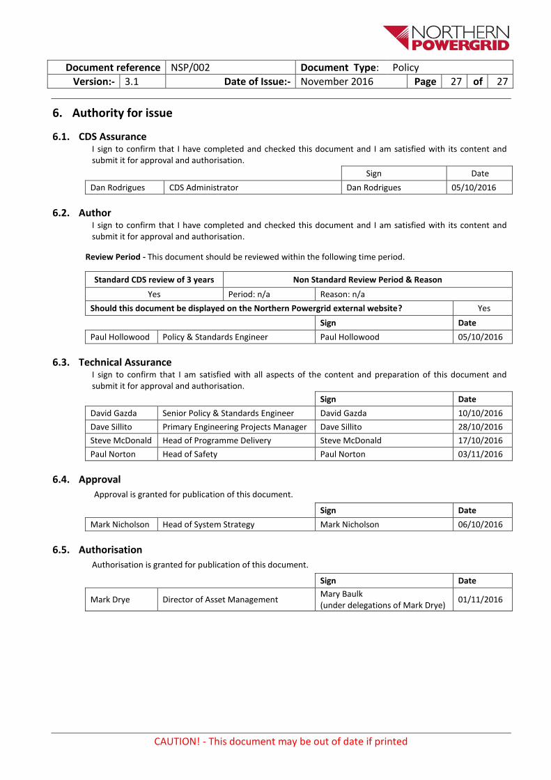
Document reference NSP/002 Document Type: Policy
Version:- 3.1 Date of Issue:- November 2016 Page 27 of 27
CAUTION! - This document may be out of date if printed
6. Authority for issue
6.1. CDS Assurance I sign to confirm that I have completed and checked this document and I am satisfied with its content and submit it for approval and authorisation.
Sign Date
Dan Rodrigues CDS Administrator Dan Rodrigues 05/10/2016
6.2. Author I sign to confirm that I have completed and checked this document and I am satisfied with its content and submit it for approval and authorisation.
Review Period - This document should be reviewed within the following time period.
Standard CDS review of 3 years Non Standard Review Period & Reason
Yes Period: n/a Reason: n/a
Should this document be displayed on the Northern Powergrid external website? Yes
Sign Date
Paul Hollowood Policy & Standards Engineer Paul Hollowood 05/10/2016
6.3. Technical Assurance I sign to confirm that I am satisfied with all aspects of the content and preparation of this document and submit it for approval and authorisation.
Sign Date
David Gazda Senior Policy & Standards Engineer David Gazda 10/10/2016
Dave Sillito Primary Engineering Projects Manager Dave Sillito 28/10/2016
Steve McDonald Head of Programme Delivery Steve McDonald 17/10/2016
Paul Norton Head of Safety Paul Norton 03/11/2016
6.4. Approval
Approval is granted for publication of this document.
Sign Date
Mark Nicholson Head of System Strategy Mark Nicholson 06/10/2016
6.5. Authorisation
Authorisation is granted for publication of this document.
Sign Date
Mark Drye Director of Asset Management Mary Baulk (under delegations of Mark Drye)
01/11/2016