Embed Size (px)
Citation preview
Features
The NSM free cooling glycol free designed and man-ufactured to meet air conditioning requirements in residential/commercial buildings or to meet refrigeration requirements in industrial facilities.These are outdoor units with screw compressors, axial fans, micro-channel coils, and shell and tube heat exchangers. The base, the structure and the panels are made of steel treated with rustproof polyester paint.These chillers are provided with a "free cooling" coil and a intermediate plate heat exchanger, in order to accomplish a double set of independent, a coil circuit / a plant circuit.These chillers are used when the refrigerant load request persists even during the winter months, or when the outdoor air temperature is below the temperature of the return liquid from the system. In Free cooling operation (mixed Free cooling and compressors, or Free cooling only), the fluid is cooled directly by the outdoor air, allowing even the complete shutdown of compressors with a significant energy saving.
VersionsNSM_B Free cooling glycol freeNSM_G Free cooling plus glycol free
Operating range: Work up to 50°C of outdoor air temperature at full load, depending on size and version. For further details refer to the selection software/technical documentation.• Unit with 2/3 refrigerant circuits designed to
provide maximum efficiency at full load, ensur-ing high efficiency at partial loads also and ensuring continuity in case one of the circuits stop.
• The full range uses aluminium micro-channel coils, ensuring very high levels of efficiency. This allows using less refrigerant compared to traditional copper/aluminium coils.
• he possibility of using the electronic thermo-static valve brings significant benefits, in par-ticular when the refrigerant is working at par-tial loads to the benefit of energy efficiency of the unit. IT is supplied as standard from size 5202÷6402 e 8403÷9603, optional for all other sizes.
• Intermediate plate heat exchanger, it permits to obtain a double circuit set:
Coil circuit with glycol, in order to protect the component from freezing.
Primary plant circuit, without glycol.• Standard differential pressure switch• DCPX series• Device for electronically controlling the series
condensation, for operation even at low tem-peratures or in free cooling, which allows adjusting the air flow rate to actual system demand with resulting advantages in terms of consumption reduction.
• Microprocessor adjustment, that allows isolat-ing the condenser coils to maximise the free cooling efficiency, even in mixed Free cooling and compressor operation
- Complete, with keyboard and LCD display, for easy consultation and intervention on the unit via a menu available in several languages.
- The presence of a programmable timer allows setting time bands of operation and a possible second set-point
- The temperature control takes place with the integral proportional logic, based on the water
output temperature.- Night Mode: it is possible to set a silenced
operation profile. Perfect for night operation, since it guarantees
greater acoustic comfort in the evenings, and a high efficiency in the time of greater load.
Air/Water chillers for outdoor installation with free cooling glycol freeScrew compressors, shell and tube heat exchangers and axial fansCooling capacity from 306÷2028kWNSM
R134a
glycol free1 4 0 2 / 9 6 0 3
• HIGH EFFICIENCY ALSO AT PARTIAL LOADS• ENERGY SAVING• MICRO-CHANNEL COIL• QUICK AND EASY INSTALLATION• NIGHT MODE
Note:(1) Accessori applicabili solo in fabbrica(2) L’accessorio KRSDES/KRSREC comprende la resitenza elettrica evaporatore più la resitenza elettrica recuperatori
(1) Contattare la sede per temperature inferiori (2) Il desurriscaldatore può essere usato esclusivamente nel funzionamento a freddo
Mod. vers. 1402 1602 1802 2002 2202 2352 2502 2652 2802 3002 3202 3402 3602 3902 4202 4502AER485P1 •(x2) •(x2) •(x2) •(x2) •(x2) •(x2) •(x2) •(x2) •(x2) •(x2) •(x2) •(x2) •(x2) •(x2) •(x2) •(x2)AERWEB300 • • • • • • • • • • • • • • • •
PRV3 • • • • • • • • • • • • • • • •
MULTICHILLER_PCO • • • • • • • • • • • • • • • •
AVX (1) • • • • • • • • • • • • • • • •
Accessories mounted in the factory;KRS (2) A 22 22 23 23 23 23 23 23 23 23 23 24 24 24 24 24
E 23 23 23 23 23 23 23 23 23 23 23 24 24 24 24 24U 23 23 23 23 23 23 23 23 23 23 23 24 24 24 24 24N 23 23 23 23 23 23 23 23 23 23 23 24 24 24 24 23+23
KDI (1) • • • • • • • • • • • • • • • •
RIFNSM 1402 1602 1802 2002 2202 2352 2502 2652 2802 3002 3202 3402 3602 3902 4202 4502GPes. (GP4V)
A 4V 4V 4V 4V 5V 5V 5V 6V 6V 6V 6V 7V 7V 8V 8V 9VE 4V 4V 5V 5V 5V 6V 6V 7V 7V 7V 7V 8V 8V 9V 10V 10VU 4V 4V 5V 5V 5V 6V 6V 7V 7V 7V 7V 8V 8V 9V 10V 10VN 5V 5V 6V 6V 6V 7V 7V 8V 8V 8V 8V 9V 10V 11V 11V 6V+7V
AK (3) • • • • • • • • • • • • • • • •
4802 5202 5602 6002 6402 6503 6703 6903 7203 8403 9603AER485P1 •(x2) •(x2) •(x2) •(x2) •(x2) •(x3) •(x3) •(x3) •(x3) •(x3) •(x3)AERWEB300 • • • • • • • • • • •
PRV3 • • • • • • • • • • •
MULTICHILLER_PCO • • • • • • • • • • •
AVX (1) • • • • • • • • • • •
Accessories mounted in the factory;KRS (2) A 24 24 24 24 24 24+23 24+23 24+23 24+23 24+23 24+23
E 24 24 23+23 23+23 23+23 24+23 24+23 24+23 24+23U 24 24 23+23 23+23 23+23 24+23 24+23 24+23 24+23N 23+23 23+23 23+23 23+23 23+23 24+23
KDI (1) • • • • • • • • • • •
RIFNSM 4802 5202 5602 6002 6402 6503 6703 6903 7203 8403 9603GPes. (GP9V)
A 9V 9V 10V 11V 11V 8V+4V 8V+4V 9V+5V 9V+5V 10V+5V 11V+6VE 11V 11V 6V+6V 6V+7V 7V+7V 9V+5V 10V+5V 10V+5V 11V+6VU 11V 11V 6V+6V 6V+7V 7V+7V 9V+5V 10V+5V 10V+5V 11V+6VN 7V+7V 7V+8V 8V+8V 8V+8V 8V+8V 11V+6V
AK (3) • • • • • • • • • • •
Accessories compatibility
(1) Accessories to be defined for compatibility(2) Compulsory accessory(3) The accessory is only available for the "E/N" silenced versions(x2) Indicates the amount to order
Accessories
• AER485P1: RS-485 interface for supervising sys-tems with MODBUS protocol.
• AERWEB300: the AERWEB device allows the remote control of a chiller by means of a com-mon PC through Ethernet connection, via a common browser; 4 models available:
AERWEB300-6: Web server for monitoring and con-trolling maximum 6 RS485 network devices;
AERWEB300-18: Web server for monitoring and controlling maximum 18 RS485 network devices;
AERWEB300-6G: Web server for monitoring and controlling maximum 6 RS485 network devices with integrated GPRS modem;
AERWEB300-18G: Web server for monitoring and controlling maximum 18 RS485 network
devices with integrated GPRS modem;• PRV3: Allows you to control the chiller at a dis-
tance.• MULTICHILLER_PCO: Control, switch-on and
switch-off system of the single chillers where multiple units are installed in parallel, always ensuring constant flow rate to the evaporators.
• AVX: Spring anti-vibration mounts.
Accessories mounted in the factory;• KRS: (compulsory accessory) Exchangers
electric resistance • KDI: double thickness evaporator insulation.
Provides stand-still protection down to -20°C.
Must be ordered in conjunction with options KRS
• RIFNSM: Current power factor correction. Connected in parallel to the motor, it allows a reduction of the input current (approx. 10%).
• GP: Anti-intrusion grids.• AK: ACOUSTIC KIT. This accessory further reduce the noise.
Field Description1,2,3 NSM4,5,6,7 Sizes
1402-1602-1802-2002-2202-2352-2502-2652-2802-3002-3202 (dual circuit)3402-3602-3902-4202-4502-4802-5202-5602-6002-6402 (dual circuit)6503-6703-6903-7203-8403-9603 (triple circuit)
8 Scope of application° Standard (temperature of water produced up to +4 °C) (3)
Y Low temperature (temperature of water produced from +4°C to -6°C) (4)X Electronic thermostatic valve (temperature of water produced up to +4 °C) Z Low temperature electronic thermostatic valve (temperature of water produced from +4°C to -6°C) (4)
9 ModelB Free cooling glycol freeG Free cooling Plus glycol free (5)
10 Heat recovery° Without heat recovery
11 VersionA High efficiencyE Silenced high efficiencyU Very high efficiencyN Silenced very high efficiency
12 Condensing coils° Aluminium microchannel
O Painted aluminium microchannelR Copper - CopperS Copper - ThinnedV Epoxy paint (only free cooling coil)
13 Fans° Standard
M IncreasedJ Inverter
14 Power supply ° 400V/3/50Hz with fuses8 400V/3/50Hz with magnet circuit breakers2 230V/3/50Hz with fuses (6)4 230V/3/50Hz with magnet circuit breakers (6)5 500V/3/50Hz with fuses (7)9 500V/3/50Hz with magnet circuit breakers (7)
15-16 Integrated hydronic kit00 Without hydronic kit
Free cooling water coilsCopper Aluminium Painted Aluminium CopperCopper CopperCopper - ThinnedEpoxy paint (only free cooling coil)
By appropriately combining the variety of options available, every model can be configured in order to meet all specific system requirements.
Choosing the unit
(3)sizes from 5202÷6402 and 8403÷9603 come standard with the electronic thermostatic valve (4) The Y/Z option is not compatible with the D option(5) The free cooling plus models can have coils only in options "°" and "O" (6) 230V/3/50Hz available only for sizes from 1402÷2202(7) 500V/3/50Hz available only for sizes from 1402÷3202
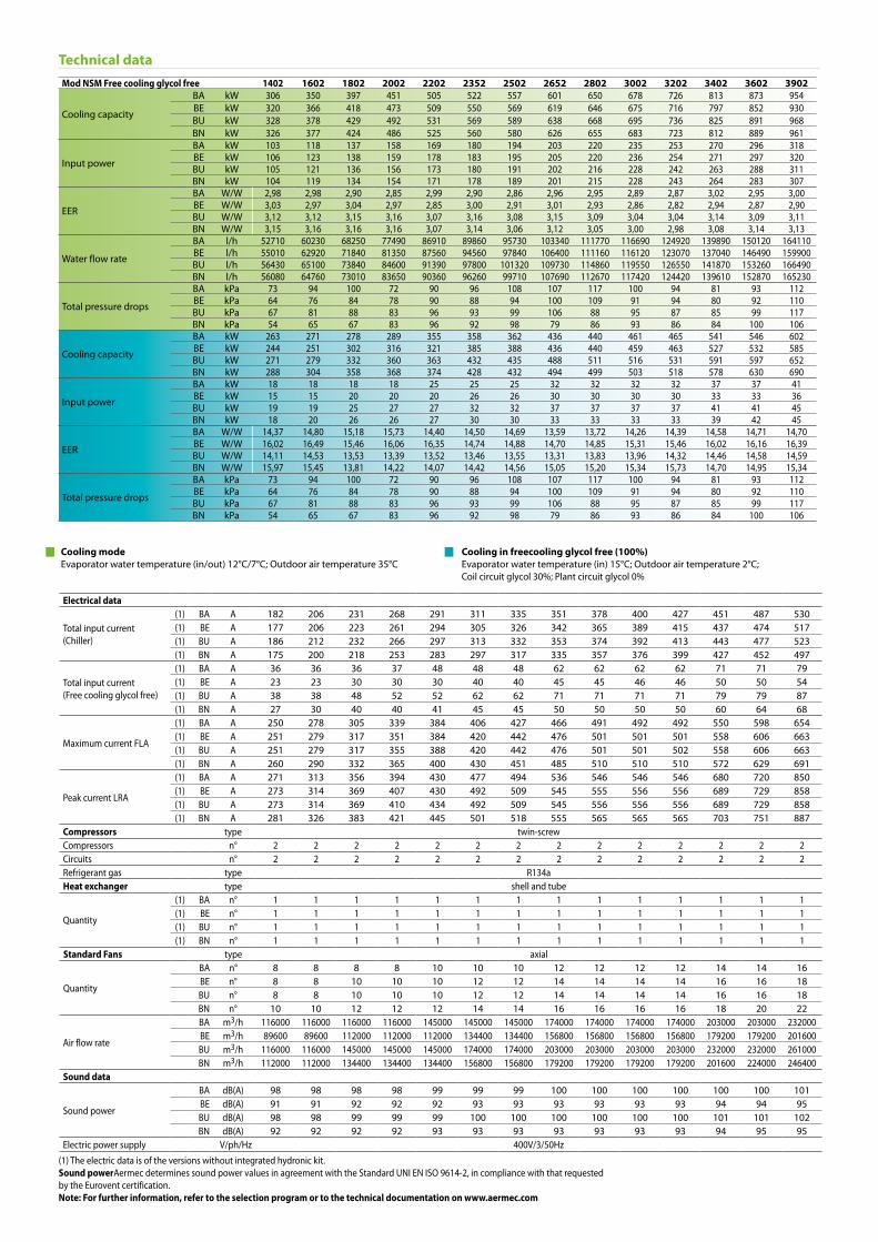
Mod NSM Free cooling glycol free 1402 1602 1802 2002 2202 2352 2502 2652 2802 3002 3202 3402 3602 3902
Cooling capacity
BA kW 306 350 397 451 505 522 557 601 650 678 726 813 873 954BE kW 320 366 418 473 509 550 569 619 646 675 716 797 852 930BU kW 328 378 429 492 531 569 589 638 668 695 736 825 891 968BN kW 326 377 424 486 525 560 580 626 655 683 723 812 889 961
Input power
BA kW 103 118 137 158 169 180 194 203 220 235 253 270 296 318BE kW 106 123 138 159 178 183 195 205 220 236 254 271 297 320BU kW 105 121 136 156 173 180 191 202 216 228 242 263 288 311BN kW 104 119 134 154 171 178 189 201 215 228 243 264 283 307
EER
BA W/W 2,98 2,98 2,90 2,85 2,99 2,90 2,86 2,96 2,95 2,89 2,87 3,02 2,95 3,00BE W/W 3,03 2,97 3,04 2,97 2,85 3,00 2,91 3,01 2,93 2,86 2,82 2,94 2,87 2,90BU W/W 3,12 3,12 3,15 3,16 3,07 3,16 3,08 3,15 3,09 3,04 3,04 3,14 3,09 3,11BN W/W 3,15 3,16 3,16 3,16 3,07 3,14 3,06 3,12 3,05 3,00 2,98 3,08 3,14 3,13
Water flow rate
BA l/h 52710 60230 68250 77490 86910 89860 95730 103340 111770 116690 124920 139890 150120 164110BE l/h 55010 62920 71840 81350 87560 94560 97840 106400 111160 116120 123070 137040 146490 159900BU l/h 56430 65100 73840 84600 91390 97800 101320 109730 114860 119550 126550 141870 153260 166490BN l/h 56080 64760 73010 83650 90360 96260 99710 107690 112670 117420 124420 139610 152870 165230
Total pressure drops
BA kPa 73 94 100 72 90 96 108 107 117 100 94 81 93 112BE kPa 64 76 84 78 90 88 94 100 109 91 94 80 92 110BU kPa 67 81 88 83 96 93 99 106 88 95 87 85 99 117BN kPa 54 65 67 83 96 92 98 79 86 93 86 84 100 106
Cooling capacity
BA kW 263 271 278 289 355 358 362 436 440 461 465 541 546 602BE kW 244 251 302 316 321 385 388 436 440 459 463 527 532 585BU kW 271 279 332 360 363 432 435 488 511 516 531 591 597 652BN kW 288 304 358 368 374 428 432 494 499 503 518 578 630 690
Input power
BA kW 18 18 18 18 25 25 25 32 32 32 32 37 37 41BE kW 15 15 20 20 20 26 26 30 30 30 30 33 33 36BU kW 19 19 25 27 27 32 32 37 37 37 37 41 41 45BN kW 18 20 26 26 27 30 30 33 33 33 33 39 42 45
EER
BA W/W 14,37 14,80 15,18 15,73 14,40 14,50 14,69 13,59 13,72 14,26 14,39 14,58 14,71 14,70BE W/W 16,02 16,49 15,46 16,06 16,35 14,74 14,88 14,70 14,85 15,31 15,46 16,02 16,16 16,39BU W/W 14,11 14,53 13,53 13,39 13,52 13,46 13,55 13,31 13,83 13,96 14,32 14,46 14,58 14,59BN W/W 15,97 15,45 13,81 14,22 14,07 14,42 14,56 15,05 15,20 15,34 15,73 14,70 14,95 15,34
Total pressure drops
BA kPa 73 94 100 72 90 96 108 107 117 100 94 81 93 112BE kPa 64 76 84 78 90 88 94 100 109 91 94 80 92 110BU kPa 67 81 88 83 96 93 99 106 88 95 87 85 99 117BN kPa 54 65 67 83 96 92 98 79 86 93 86 84 100 106
Electrical data
Total input current(Chiller)
(1) BA A 182 206 231 268 291 311 335 351 378 400 427 451 487 530(1) BE A 177 206 223 261 294 305 326 342 365 389 415 437 474 517(1) BU A 186 212 232 266 297 313 332 353 374 392 413 443 477 523(1) BN A 175 200 218 253 283 297 317 335 357 376 399 427 452 497
Total input current (Free cooling glycol free)
(1) BA A 36 36 36 37 48 48 48 62 62 62 62 71 71 79(1) BE A 23 23 30 30 30 40 40 45 45 46 46 50 50 54(1) BU A 38 38 48 52 52 62 62 71 71 71 71 79 79 87(1) BN A 27 30 40 40 41 45 45 50 50 50 50 60 64 68
Maximum current FLA
(1) BA A 250 278 305 339 384 406 427 466 491 492 492 550 598 654(1) BE A 251 279 317 351 384 420 442 476 501 501 501 558 606 663(1) BU A 251 279 317 355 388 420 442 476 501 501 502 558 606 663(1) BN A 260 290 332 365 400 430 451 485 510 510 510 572 629 691
Peak current LRA
(1) BA A 271 313 356 394 430 477 494 536 546 546 546 680 720 850(1) BE A 273 314 369 407 430 492 509 545 555 556 556 689 729 858(1) BU A 273 314 369 410 434 492 509 545 556 556 556 689 729 858(1) BN A 281 326 383 421 445 501 518 555 565 565 565 703 751 887
Compressors type twin-screwCompressors n° 2 2 2 2 2 2 2 2 2 2 2 2 2 2Circuits n° 2 2 2 2 2 2 2 2 2 2 2 2 2 2Refrigerant gas type R134aHeat exchanger type shell and tube
Quantity
(1) BA n° 1 1 1 1 1 1 1 1 1 1 1 1 1 1(1) BE n° 1 1 1 1 1 1 1 1 1 1 1 1 1 1(1) BU n° 1 1 1 1 1 1 1 1 1 1 1 1 1 1(1) BN n° 1 1 1 1 1 1 1 1 1 1 1 1 1 1
Standard Fans type axial
Quantity
BA n° 8 8 8 8 10 10 10 12 12 12 12 14 14 16BE n° 8 8 10 10 10 12 12 14 14 14 14 16 16 18BU n° 8 8 10 10 10 12 12 14 14 14 14 16 16 18BN n° 10 10 12 12 12 14 14 16 16 16 16 18 20 22
Air flow rate
BA m3/h 116000 116000 116000 116000 145000 145000 145000 174000 174000 174000 174000 203000 203000 232000BE m3/h 89600 89600 112000 112000 112000 134400 134400 156800 156800 156800 156800 179200 179200 201600BU m3/h 116000 116000 145000 145000 145000 174000 174000 203000 203000 203000 203000 232000 232000 261000BN m3/h 112000 112000 134400 134400 134400 156800 156800 179200 179200 179200 179200 201600 224000 246400
Sound data
Sound power
BA dB(A) 98 98 98 98 99 99 99 100 100 100 100 100 100 101BE dB(A) 91 91 92 92 92 93 93 93 93 93 93 94 94 95BU dB(A) 98 98 99 99 99 100 100 100 100 100 100 101 101 102BN dB(A) 92 92 92 92 93 93 93 93 93 93 93 94 95 95
Electric power supply V/ph/Hz 400V/3/50Hz
(1) The electric data is of the versions without integrated hydronic kit.Sound powerAermec determines sound power values in agreement with the Standard UNI EN ISO 9614-2, in compliance with that requested by the Eurovent certification.Note: For further information, refer to the selection program or to the technical documentation on www.aermec.com
Technical data
Cooling modeEvaporator water temperature (in/out) 12°C/7°C; Outdoor air temperature 35°C
Cooling in freecooling glycol free (100%)Evaporator water temperature (in) 15°C; Outdoor air temperature 2°C; Coil circuit glycol 30%; Plant circuit glycol 0%

Technical dataMod NSM Free cooling glycol free 4202 4502 4802 5202 5602 6002 6402 6503 6703 6903 7203 8403 9603
Cooling capacity
BA kW 997 1082 1128 1167 1223 1305 1347 1459 1502 1659 1705 1838 2028BE kW 995 1052 1137 1159 1217 1279 1342 1434 1500 1599 1684BU kW 1031 1095 1181 1209 1266 1326 1387 1491 1554 1667 1753BN kW 1005 1099 1162 1218 1274 1318 1362 1478
Input power
BA kW 346 366 392 422 439 453 472 492 520 557 583 659 704BE kW 340 370 389 418 437 449 461 491 511 569 588BU kW 332 358 379 405 426 440 454 478 499 550 570BN kW 333 350 369 393 416 434 451 472
EER
BA W/W 2,88 2,96 2,88 2,76 2,79 2,88 2,85 2,97 2,89 2,98 2,92 2,79 2,88BE W/W 2,93 2,84 2,92 2,77 2,79 2,85 2,91 2,92 2,93 2,81 2,86BU W/W 3,11 3,06 3,12 2,98 2,97 3,01 3,06 3,12 3,12 3,03 3,07BN W/W 3,02 3,14 3,15 3,10 3,06 3,04 3,02 3,13
Water flow rate
BA l/h 171460 186150 194070 200780 210330 224450 231640 250990 258340 285350 293260 316150 348840BE l/h 171170 180890 195570 199390 209370 220070 230760 246660 257930 274970 289650BU l/h 177350 188350 203160 207920 217720 228110 238500 256480 267340 286650 301470BN l/h 172840 188960 199810 209510 219210 226710 234210 254300
Total pressure drops
BA kPa 122 132 143 116 109 125 133 112 127 132 143 108 135BE kPa 125 128 130 135 84 115 112 110 121 121 130BU kPa 119 137 138 145 104 124 113 117 119 137 138BN kPa 116 103 104 109 72 78 81 105
Cooling capacity
BA kW 606 682 684 687 746 800 803 894 899 1043 1047 1133 1260BE kW 647 665 718 720 784 836 891 904 966 995 1048BU kW 739 746 804 806 890 942 995 1015 1102 1130 1188BN kW 697 817 864 930 987 1002 1007 1064
Input power
BA kW 41 45 45 45 60 64 64 59 59 70 70 77 85BE kW 42 42 45 45 52 56 59 55 62 64 67BU kW 52 52 56 56 66 69 73 72 79 81 85BN kW 45 56 59 62 66 66 66 72
EER
BA W/W 14,82 15,19 15,23 15,31 12,45 12,56 12,60 15,08 15,17 15,00 15,04 14,72 14,87BE W/W 15,27 15,66 15,88 15,91 15,02 15,00 15,01 16,33 15,57 15,47 15,62BU W/W 14,09 14,22 14,29 14,33 13,55 13,56 13,57 14,19 13,90 13,90 13,96BN W/W 15,49 14,64 14,56 14,89 15,05 15,27 15,34 14,87
Total pressure drops
BA kPa 122 132 143 116 109 125 133 112 127 132 143 108 135BE kPa 125 128 130 135 84 115 112 110 121 121 130BU kPa 119 137 138 145 104 124 113 117 119 137 138BN kPa 116 103 104 109 72 78 81 105
Electrical data
Total input current(Chiller)
(1) BA A 581 614 655 704 733 761 796 821 872 945 986 1100 1198(1) BE A 555 601 632 678 708 732 755 804 832 924 945(1) BU A 564 605 639 682 718 746 774 812 846 926 954(1) BN A 544 570 600 639 677 708 740 771
Total input current (Free cooling glycol free)
(1) BA A 79 87 87 87 114 121 121 116 116 135 135 149 165(1) BE A 64 64 68 68 80 86 91 84 94 98 102(1) BU A 100 100 108 108 126 134 141 139 152 156 163(1) BN A 68 86 91 95 100 100 100 109
Maximum current FLA
(1) BA A 702 750 789 832 903 951 985 1005 1053 1152 1192 1335 1455(1) BE A 725 764 818 861 920 964 1008 1026 1089 1171 1218(1) BU A 725 764 818 861 922 965 1008 1030 1093 1174 1221(1) BN A 739 805 854 906 958 992 1026 1064
Peak current LRA
(1) BA A 876 949 972 1127 1202 1328 1325 1094 1121 1229 1252 1515 1639(1) BE A 900 964 1001 1156 1219 1341 1348 1115 1156 1247 1278(1) BU A 900 964 1001 1156 1221 1342 1348 1119 1160 1250 1281(1) BN A 914 1004 1037 1201 1257 1369 1366 1153
Compressors type twin-screwCompressors n° 2 2 2 2 2 2 3 3 3 3 3 3 3Circuits n° 2 2 2 2 2 2 3 3 3 3 3 3 3Refrigerant gas type R134aHeat exchanger type shell and tube
Quantity
(1) BA n° 1 1 1 1 1 1 1 2 2 2 2 2 2(1) BE n° 1 1 1 1 2 2 2 2 2 2 2(1) BU n° 1 1 1 1 2 2 2 2 2 2 2(1) BN n° 1 2 2 2 2 2 2 2
Standard Fans type axial
Quantity
BA n° 16 18 18 18 20 22 22 24 24 28 28 30 34BE n° 20 20 22 22 24 26 28 28 30 30 32BU n° 20 20 22 22 24 26 28 28 30 30 32BN n° 22 26 28 30 32 32 32 34
Air flow rate
BA m3/h 232000 261000 261000 261000 290000 319000 319000 348000 348000 406000 406000 435000 493000BE m3/h 224000 224000 246400 246400 268800 291200 313600 313600 336000 336000 358400BU m3/h 290000 290000 319000 319000 348000 377000 406000 406000 435000 435000 464000BN m3/h 246400 291200 313600 336000 358400 358400 358400 380800
Sound data
Sound power
BA dB(A) 101 102 102 102 102 102 102 103 103 103 103 104 104BE dB(A) 95 95 95 96 96 96 96 96 96 96 97BU dB(A) 102 102 102 102 103 103 103 103 104 104 104BN dB(A) 95 96 96 97 97 97 97 97
Electric power supply V/ph/Hz 400V/3/50Hz
(1) The electric data is of the versions without integrated hydronic kit.Sound powerAermec determines sound power values in agreement with the Standard UNI EN ISO 9614-2, in compliance with that requested by the Eurovent certification.Note: For further information, refer to the selection program or to the technical documentation on www.aermec.com
Cooling modeEvaporator water temperature (in/out) 12°C/7°C; Outdoor air temperature 35°C
Cooling in freecooling glycol free (100%)Evaporator water temperature (in) 15°C; Outdoor air temperature 2°C; Coil circuit glycol 30%; Plant circuit glycol 0%
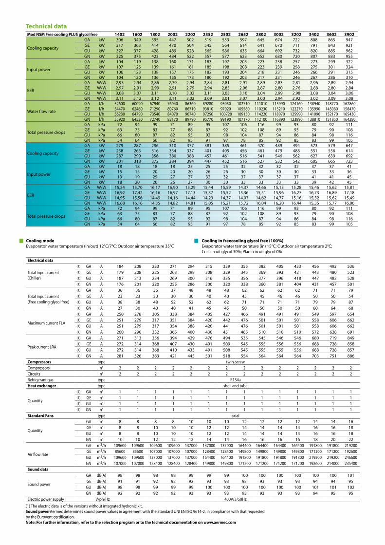
Mod NSM Free cooling PLUS glycol free 1402 1602 1802 2002 2202 2352 2502 2652 2802 3002 3202 3402 3602 3902
Cooling capacity
GA kW 306 349 395 447 502 519 553 597 645 674 722 808 865 947GE kW 317 363 414 470 504 545 564 614 641 670 711 791 843 921GU kW 327 377 428 489 528 565 586 635 664 692 732 820 885 962GN kW 325 375 423 484 522 557 577 623 652 680 720 807 883 955
Input power
GA kW 104 119 138 160 171 183 197 205 223 238 257 273 299 322GE kW 107 125 139 161 181 185 198 208 223 239 258 275 301 324GU kW 106 123 138 157 175 182 193 204 218 231 246 266 291 315GN kW 104 120 136 155 173 180 192 203 217 231 246 267 286 310
EER
GA W/W 2,95 2,94 2,86 2,79 2,94 2,84 2,81 2,91 2,89 2,83 2,81 2,96 2,89 2,94GE W/W 2,97 2,91 2,99 2,91 2,79 2,94 2,85 2,96 2,87 2,80 2,76 2,88 2,80 2,84GU W/W 3,08 3,07 3,11 3,10 3,02 3,11 3,03 3,10 3,04 2,99 2,98 3,08 3,04 3,06GN W/W 3,11 3,12 3,12 3,11 3,02 3,09 3,01 3,07 3,00 2,94 2,92 3,02 3,09 3,08
Water flow rate
GA l/h 52600 60090 67940 76940 86360 89280 95050 102710 111010 115990 124160 138940 148770 162860GE l/h 54470 62460 71290 80760 86710 93810 97020 105580 110230 115210 122270 135990 145080 158470GU l/h 56230 64790 73540 84070 90740 97250 100720 109150 114220 118970 125990 141090 152170 165430GN l/h 55920 64530 72740 83170 89790 95770 99190 107170 112100 116890 123890 138810 151850 164280
Total pressure drops
GA kPa 72 94 99 71 89 95 107 106 116 99 93 80 92 111GE kPa 63 75 83 77 88 87 92 102 108 89 93 79 90 108GU kPa 66 80 87 82 95 92 98 104 87 94 86 84 98 116GN kPa 54 64 66 82 95 91 97 78 85 92 85 83 99 105
Cooling capacity
GA kW 279 287 296 310 377 381 385 461 470 489 494 573 579 647GE kW 258 265 316 334 337 401 405 456 461 479 488 551 556 614GU kW 287 299 356 380 388 457 461 516 541 546 562 627 639 692GN kW 301 318 372 384 394 447 452 516 527 532 542 605 665 723
Input power
GA kW 18 18 18 18 25 25 25 32 32 32 32 37 37 41GE kW 15 15 20 20 20 26 26 30 30 30 30 33 33 36GU kW 19 19 25 27 27 32 32 37 37 37 37 41 41 45GN kW 18 20 26 26 27 30 30 33 33 33 33 39 42 45
EER
GA W/W 15,24 15,70 16,17 16,90 15,29 15,44 15,59 14,37 14,66 15,13 15,28 15,46 15,62 15,81GE W/W 16,92 17,42 16,16 16,97 17,13 15,37 15,52 15,36 15,51 15,96 16,27 16,73 16,89 17,18GU W/W 14,95 15,56 14,49 14,16 14,44 14,23 14,37 14,07 14,62 14,77 15,16 15,32 15,62 15,49GN W/W 16,68 16,16 14,35 14,82 14,81 15,05 15,21 15,72 16,04 16,20 16,44 15,35 15,77 16,06
Total pressure drops
GA kPa 72 94 99 71 89 95 107 106 116 99 93 80 92 111GE kPa 63 75 83 77 88 87 92 102 108 89 93 79 90 108GU kPa 66 80 87 82 95 92 98 104 87 94 86 84 98 116GN kPa 54 64 66 82 95 91 97 78 85 92 85 83 99 105
Electrical data
Total input current(Chiller)
(1) GA A 184 208 233 271 294 315 339 355 382 405 433 456 492 536(1) GE A 179 208 225 263 298 308 329 345 369 393 421 443 480 523(1) GU A 187 213 234 269 300 316 335 356 377 396 418 447 482 528(1) GN A 176 201 220 255 286 300 320 338 360 381 404 431 457 501
Total input current (Free cooling glycol free)
(1) GA A 36 36 36 37 48 48 48 62 62 62 62 71 71 79(1) GE A 23 23 30 30 30 40 40 45 45 46 46 50 50 54(1) GU A 38 38 48 52 52 62 62 71 71 71 71 79 79 87(1) GN A 27 30 40 40 41 45 45 50 50 50 50 60 64 68
Maximum current FLA
(1) GA A 250 278 305 338 384 405 427 466 491 491 491 549 597 654(1) GE A 251 279 317 351 384 420 442 476 501 501 501 558 606 662(1) GU A 251 279 317 354 388 420 441 476 501 501 501 558 606 662(1) GN A 260 290 332 365 400 430 451 485 510 510 510 572 628 691
Peak current LRA
(1) GA A 271 313 356 394 429 476 494 535 545 546 546 680 719 849(1) GE A 272 314 368 407 430 491 509 545 555 556 556 688 728 858(1) GU A 272 314 368 410 433 491 508 545 555 555 556 688 728 857(1) GN A 281 326 383 421 445 501 518 554 564 564 564 703 751 886
Compressors type twin-screwCompressors n° 2 2 2 2 2 2 2 2 2 2 2 2 2 2Circuits n° 2 2 2 2 2 2 2 2 2 2 2 2 2 2Refrigerant gas type R134aHeat exchanger type shell and tube
Quantity
(1) GA n° 1 1 1 1 1 1 1 1 1 1 1 1 1 1(1) GE n° 1 1 1 1 1 1 1 1 1 1 1 1 1 1(1) GU n° 1 1 1 1 1 1 1 1 1 1 1 1 1 1(1) GN n° 1 1 1 1 1 1 1 1 1 1 1 1 1 1
Standard Fans type axial
Quantity
GA n° 8 8 8 8 10 10 10 12 12 12 12 14 14 16GE n° 8 8 10 10 10 12 12 14 14 14 14 16 16 18GU n° 8 8 10 10 10 12 12 14 14 14 14 16 16 18GN n° 10 10 12 12 12 14 14 16 16 16 16 18 20 22
Air flow rate
GA m3/h 109600 109600 109600 109600 137000 137000 137000 164400 164400 164400 164400 191800 191800 219200GE m3/h 85600 85600 107000 107000 107000 128400 128400 149800 149800 149800 149800 171200 171200 192600GU m3/h 109600 109600 137000 137000 137000 164400 164400 191800 191800 191800 191800 219200 219200 246600GN m3/h 107000 107000 128400 128400 128400 149800 149800 171200 171200 171200 171200 192600 214000 235400
Sound data
Sound power
GA dB(A) 98 98 98 98 99 99 99 100 100 100 100 100 100 101GE dB(A) 91 91 92 92 92 93 93 93 93 93 93 94 94 95GU dB(A) 98 98 99 99 99 100 100 100 100 100 100 101 101 102GN dB(A) 92 92 92 92 93 93 93 93 93 93 93 94 95 95
Electric power supply V/ph/Hz 400V/3/50Hz(1) The electric data is of the versions without integrated hydronic kit.Sound powerAermec determines sound power values in agreement with the Standard UNI EN ISO 9614-2, in compliance with that requested by the Eurovent certification.Note: For further information, refer to the selection program or to the technical documentation on www.aermec.com
Technical data
Cooling modeEvaporator water temperature (in/out) 12°C/7°C; Outdoor air temperature 35°C
Cooling in freecooling glycol free (100%)Evaporator water temperature (in) 15°C; Outdoor air temperature 2°C; Coil circuit glycol 30%; Plant circuit glycol 0%
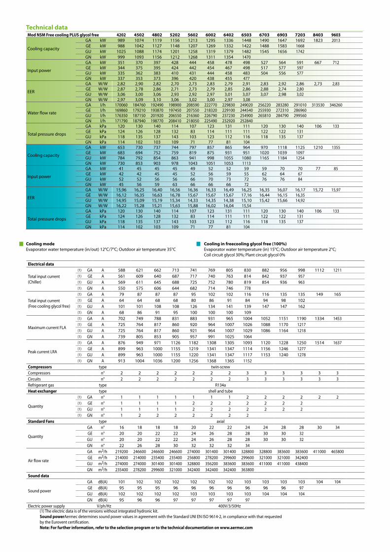
Technical dataMod NSM Free cooling PLUS glycol free 4202 4502 4802 5202 5602 6002 6402 6503 6703 6903 7203 8403 9603
Cooling capacity
GA kW 989 1074 1119 1156 1213 1295 1336 1448 1490 1647 1692 1823 2013GE kW 988 1042 1127 1148 1207 1269 1332 1422 1488 1583 1668GU kW 1025 1088 1174 1201 1258 1319 1379 1482 1545 1656 1742GN kW 999 1093 1156 1212 1268 1311 1354 1470
Input power
GA kW 351 370 397 428 444 458 478 498 527 564 591 667 712GE kW 344 375 395 424 442 454 467 498 517 577 597GU kW 335 362 383 410 431 444 458 483 504 556 577GN kW 337 353 373 396 420 438 455 477
EER
GA W/W 2,82 2,90 2,82 2,70 2,73 2,83 2,79 2,91 2,83 2,92 2,86 2,73 2,83GE W/W 2,87 2,78 2,86 2,71 2,73 2,79 2,85 2,86 2,88 2,74 2,80GU W/W 3,06 3,00 3,06 2,93 2,92 2,97 3,01 3,07 3,07 2,98 3,02GN W/W 2,97 3,09 3,10 3,06 3,02 3,00 2,97 3,08
Water flow rate
GA l/h 170060 184760 192490 198900 208590 222770 229830 249020 256220 283280 291010 313530 346260GE l/h 169860 179210 193870 197450 207550 218320 229100 244540 255930 272310 286960GU l/h 176350 187150 201920 206550 216360 226790 237230 254900 265810 284790 299560GN l/h 171790 187940 198770 208410 218050 225490 232920 252840
Total pressure drops
GA kPa 120 130 140 114 107 123 131 111 120 130 140 106 133GE kPa 124 126 128 132 83 114 111 111 122 122 131GU kPa 118 135 137 143 103 123 112 116 118 135 137GN kPa 114 102 103 109 71 77 81 104
Cooling capacity
GA kW 653 730 737 744 797 857 865 964 970 1118 1125 1210 1355GE kW 683 694 752 759 819 875 931 951 1020 1039 1097GU kW 784 792 854 863 941 998 1055 1080 1165 1184 1254GN kW 730 853 903 978 1043 1051 1053 1113
Input power
GA kW 41 45 45 45 49 52 52 59 59 70 70 77 85GE kW 42 42 45 45 52 56 59 55 62 64 67GU kW 52 52 56 56 66 70 73 72 76 76 84GN kW 45 56 59 63 66 66 66 72
EER
GA W/W 15,96 16,25 16,40 16,56 16,36 16,33 16,49 16,25 16,35 16,07 16,17 15,72 15,97GE W/W 16,12 16,35 16,63 16,78 15,67 15,67 15,67 17,16 16,44 16,15 16,35GU W/W 14,95 15,09 15,19 15,34 14,33 14,35 14,38 15,10 15,42 15,66 14,92GN W/W 16,22 15,28 15,21 15,63 15,88 16,02 16,04 15,54
Total pressure drops
GA kPa 120 130 140 114 107 123 131 111 120 130 140 106 133GE kPa 124 126 128 132 83 114 111 111 122 122 131GU kPa 118 135 137 143 103 123 112 116 118 135 137GN kPa 114 102 103 109 71 77 81 104
Electrical data
Total input current(Chiller)
(1) GA A 588 621 662 713 741 769 805 830 882 956 998 1112 1211(1) GE A 561 609 640 687 717 740 763 814 842 937 957(1) GU A 569 611 645 688 725 752 780 819 854 936 963(1) GN A 550 575 606 644 682 714 746 778
Total input current (Free cooling glycol free)
(1) GA A 79 87 87 87 95 102 102 116 116 135 135 149 165(1) GE A 64 64 68 68 80 86 91 84 94 98 102(1) GU A 101 101 108 108 126 134 141 139 147 147 162(1) GN A 68 86 91 95 100 100 100 109
Maximum current FLA
(1) GA A 702 749 788 831 883 931 965 1004 1052 1151 1190 1334 1453(1) GE A 725 764 817 860 920 964 1007 1026 1088 1170 1217(1) GU A 725 764 817 860 921 964 1007 1029 1086 1164 1218(1) GN A 739 805 853 905 957 991 1025 1064
Peak current LRA
(1) GA A 876 949 971 1126 1182 1308 1305 1093 1120 1228 1250 1514 1637(1) GE A 899 963 1000 1155 1219 1341 1347 1114 1156 1246 1277(1) GU A 899 963 1000 1155 1220 1341 1347 1117 1153 1240 1278(1) GN A 913 1004 1036 1200 1256 1368 1365 1152
Compressors type twin-screwCompressors n° 2 2 2 2 2 2 2 3 3 3 3 3 3Circuits n° 2 2 2 2 2 2 2 3 3 3 3 3 3Refrigerant gas type R134aHeat exchanger type shell and tube
Quantity
(1) GA n° 1 1 1 1 1 1 1 2 2 2 2 2 2(1) GE n° 1 1 1 1 2 2 2 2 2 2 2(1) GU n° 1 1 1 1 2 2 2 2 2 2 2(1) GN n° 1 2 2 2 2 2 2 2
Standard Fans type axial
Quantity
GA n° 16 18 18 18 20 22 22 24 24 28 28 30 34GE n° 20 20 22 22 24 26 28 28 30 30 32GU n° 20 20 22 22 24 26 28 28 30 30 32GN n° 22 26 28 30 32 32 32 34
Air flow rate
GA m3/h 219200 246600 246600 246600 274000 301400 301400 328800 328800 383600 383600 411000 465800GE m3/h 214000 214000 235400 235400 256800 278200 299600 299600 321000 321000 342400GU m3/h 274000 274000 301400 301400 328800 356200 383600 383600 411000 411000 438400GN m3/h 235400 278200 299600 321000 342400 342400 342400 363800
Sound data
Sound power
GA dB(A) 101 102 102 102 102 102 102 103 103 103 103 104 104GE dB(A) 95 95 95 96 96 96 96 96 96 96 97GU dB(A) 102 102 102 102 103 103 103 103 104 104 104GN dB(A) 95 96 96 97 97 97 97 97
Electric power supply V/ph/Hz 400V/3/50Hz(1) The electric data is of the versions without integrated hydronic kit.Sound powerAermec determines sound power values in agreement with the Standard UNI EN ISO 9614-2, in compliance with that requested by the Eurovent certification.Note: For further information, refer to the selection program or to the technical documentation on www.aermec.com
Cooling modeEvaporator water temperature (in/out) 12°C/7°C; Outdoor air temperature 35°C
Cooling in freecooling glycol free (100%)Evaporator water temperature (in) 15°C; Outdoor air temperature 2°C; Coil circuit glycol 30%; Plant circuit glycol 0%
Cod.
: SN
SMBG
UY.
00 /
1503
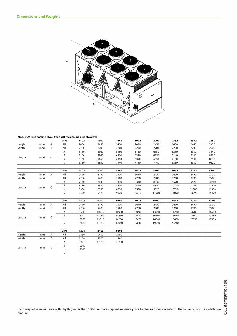
Mod. NSM Free cooling glycol free and Free cooling plus glycol freeVers 1402 1602 1802 2002 2202 2352 2502 2652
Height (mm) A All 2450 2450 2450 2450 2450 2450 2450 2450Width (mm) B All 2200 2200 2200 2200 2200 2200 2200 2200
Length (mm) C
A 5160 5160 5160 5160 6350 6350 6350 7140E 5160 5160 6350 6350 6350 7140 7140 8330U 5160 5160 6350 6350 6350 7140 7140 8330N 6350 6350 7140 7140 7140 8330 8330 9520
Vers 2802 3002 3202 3402 3602 3902 4202 4502Height (mm) A All 2450 2450 2450 2450 2450 2450 2450 2450Width (mm) B All 2200 2200 2200 2200 2200 2200 2200 2200
Length (mm) C
A 7140 7140 7140 8330 8330 9520 9520 10710E 8330 8330 8330 9520 9520 10710 11900 11900U 8330 8330 8330 9520 9520 10710 11900 11900N 9520 9520 9520 10710 11900 13090 13090 15470
Vers 4802 5202 5602 6002 6402 6503 6703 6903Height (mm) A All 2450 2450 2450 2450 2450 2450 2450 2450Width (mm) B All 2200 2200 2200 2200 2200 2200 2200 2200
Length (mm) C
A 10710 10710 11900 13090 13090 14280 14280 16660E 13090 13090 14280 15470 16660 16660 17850 17850U 13090 13090 14280 15470 16660 16660 17850 17850N 16660 17850 19040 19040 19040 20230
Vers 7203 8403 9603Height (mm) A All 2450 2450 2450Width (mm) B All 2200 2200 2200
Length (mm) C
A 16660 17850 20230E 19040U 19040N
Dimensions and Weights
For transport reasons, units with depth greater than 13090 mm are shipped separately. For further information, refer to the technical and/or installation manual.
A
B
C