Embed Size (px)
Citation preview
NSF Workshop on Polymer Processing,
June 9-10, 2004
Hari DharanUniversity of California at Berkeley
Present researchResin Transfer Molding
New concept for resin transfer molding
(RTM) in which tool articulation provides
significantly faster mold fill time
compared to conventional RTM
processes.
Outline
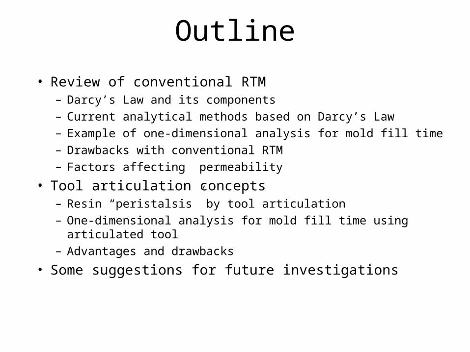
• Review of conventional RTM– Darcy’s Law and its components– Current analytical methods based on Darcy’s Law– Example of one-dimensional analysis for mold fill time– Drawbacks with conventional RTM– Factors affecting permeability
• Tool articulation concepts– Resin “peristalsis” by tool articulation – One-dimensional analysis for mold fill time using articulated tool– Advantages and drawbacks
• Some suggestions for future investigations
Introduction
In RTM, the mold is packed with a dry fiber preform in which the fibers are oriented in the desired directions for reinforcing the part.
The preform is impregnated by resin injected through one or more ports in the mold. After the mold is filled, the resin solidifies by cross-linking and the part is removed from the mold.
There are currently many analyses and computer programs that simulate the mold filling process.
Prior Work
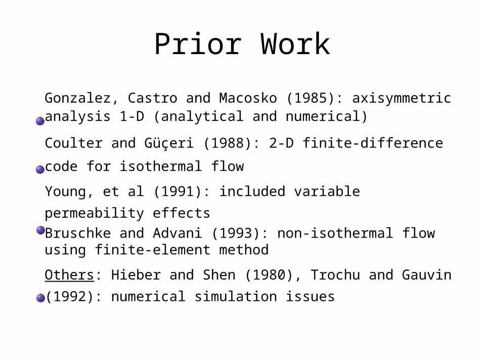
Gonzalez, Castro and Macosko (1985): axisymmetric analysis 1-D (analytical and numerical)
Coulter and Güçeri (1988): 2-D finite-difference code for
isothermal flow
Young, et al (1991): included variable permeability effects Bruschke and Advani (1993): non-isothermal flow using
finite-element method
Others: Hieber and Shen (1980), Trochu and Gauvin
(1992): numerical simulation issues
Process description of RTM
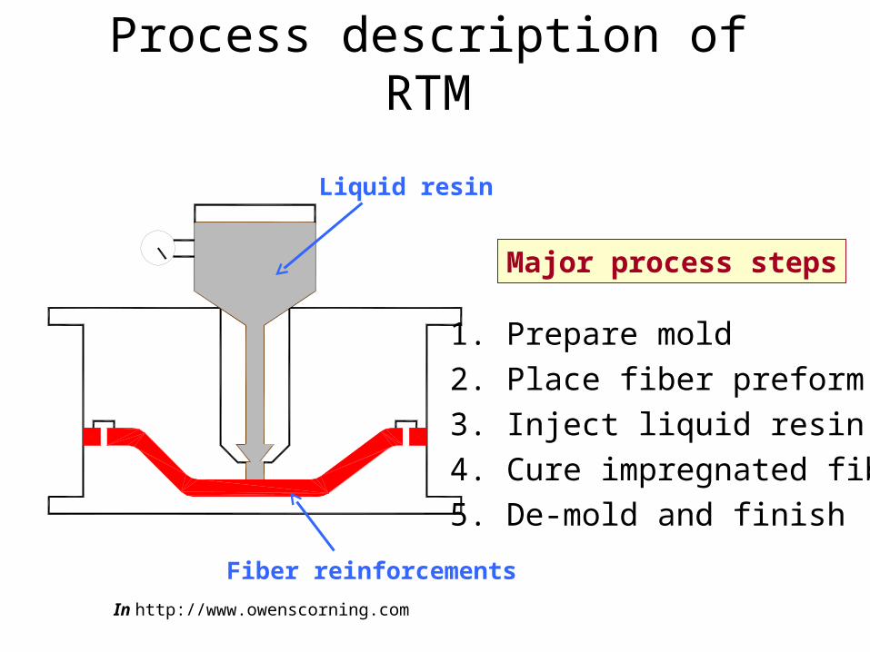
Fiber reinforcements
Liquid resin
1. Prepare mold
2. Place fiber preform
3. Inject liquid resin
4. Cure impregnated fibers
5. De-mold and finish
In http://www.owenscorning.com
Major process steps
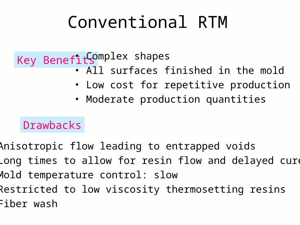
Conventional RTM
Key Benefits • Complex shapes• All surfaces finished in the mold• Low cost for repetitive production• Moderate production quantities
Drawbacks
• Anisotropic flow leading to entrapped voids• Long times to allow for resin flow and delayed cure• Mold temperature control: slow• Restricted to low viscosity thermosetting resins• Fiber wash

Ideal RTM process
• Rapid mold fill (minutes, not hours)
• No voids or resin bypass regions
• No fiber wash for various preforms
• Applicable to a variety of resin systems: hot melt epoxies, vinyl esters, thermoplastics
• Hybrid fiber preforms and embedded inserts
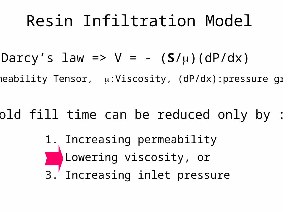
Resin Infiltration Model
• Darcy’s law => V = - (S/)(dP/dx)
S:Permeability Tensor, :Viscosity, (dP/dx):pressure gradient
• Mold fill time can be reduced only by :
1. Increasing permeability
2. Lowering viscosity, or
3. Increasing inlet pressure

1. Increasing Permeability
2. Lowering Viscosity
3. Increasing Pressure
• Decrease fiber volume fraction • Increase use of chopped and felt preformsProblem: Lowers composite properties
• Low molecular weight resins • High temperature injectionProblems: Process window and control issues
Lower Tg, modulus, compressive strength
Problems: Preform distortion and fiber wash Permeability reduction

Permeability through Fiber Preform
• In-plane components (Sx, Sy) >> Sz
• Different types of preforms will have different compliance in the thickness direction resulting in different relative permeabilities (in-plane vs thickness).
• Multi-scale permeable paths : (Preform level / fiber bundle level)
• Compressible --> Permeability = f(P)
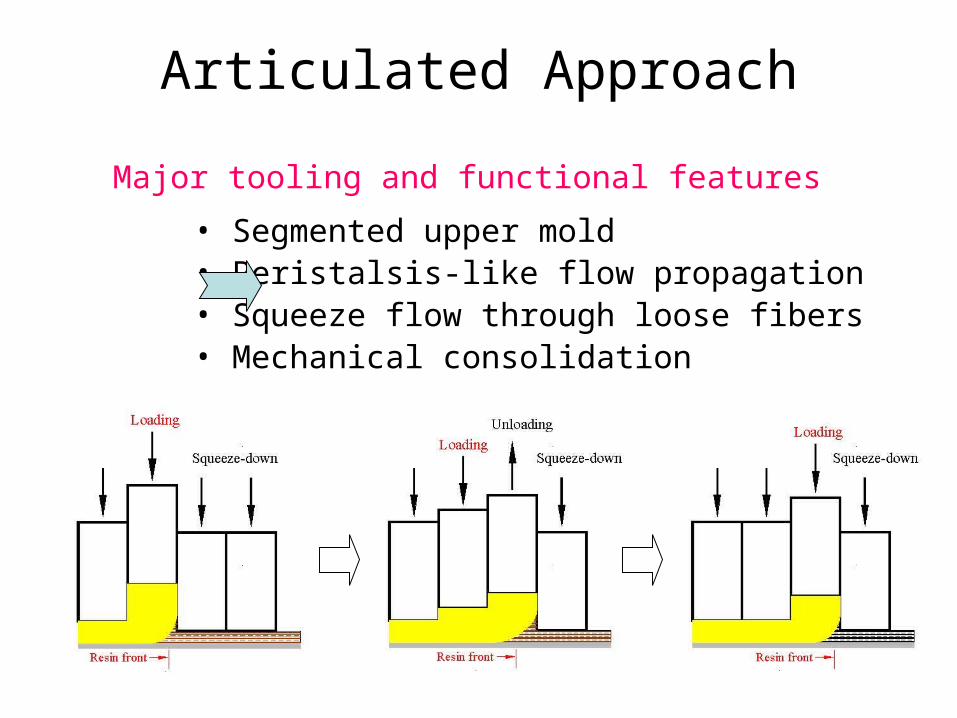
Articulated Approach
• Segmented upper mold• Peristalsis-like flow propagation• Squeeze flow through loose fibers• Mechanical consolidation
Major tooling and functional features

Articulated RTM
Loading point follows flow front
Pressure gradient is kept from degrading at constant load
Filling rate is expected to remain high
1. Liquid resin is supplied onto loose dry preform
2. Initial squeeze-down of upper mold segments
3. Transverse infiltration is driven by the first segment
4. Unloading of second segment
5. Excessive resin volume is captured by the unloading segment
Key process scheme
Result:

Analytical Approach
Process model • Unidirectional mold/ten segments• Darcy’s eqn applied to each segment
• Comparison of mold fill-time between conventional (C-) RTM and articulated (A-) RTM
• Investigation of segment controls as process parameters
Objective
Approach • Transverse flow (w.r.t. laminate) is achieved by consolidation, longitudinal flow occursthrough “loose” preform (higher S)
• Loose fiber volume fraction, Vo =0.58
• Sx/Sz=100 at a given fiber volume fraction
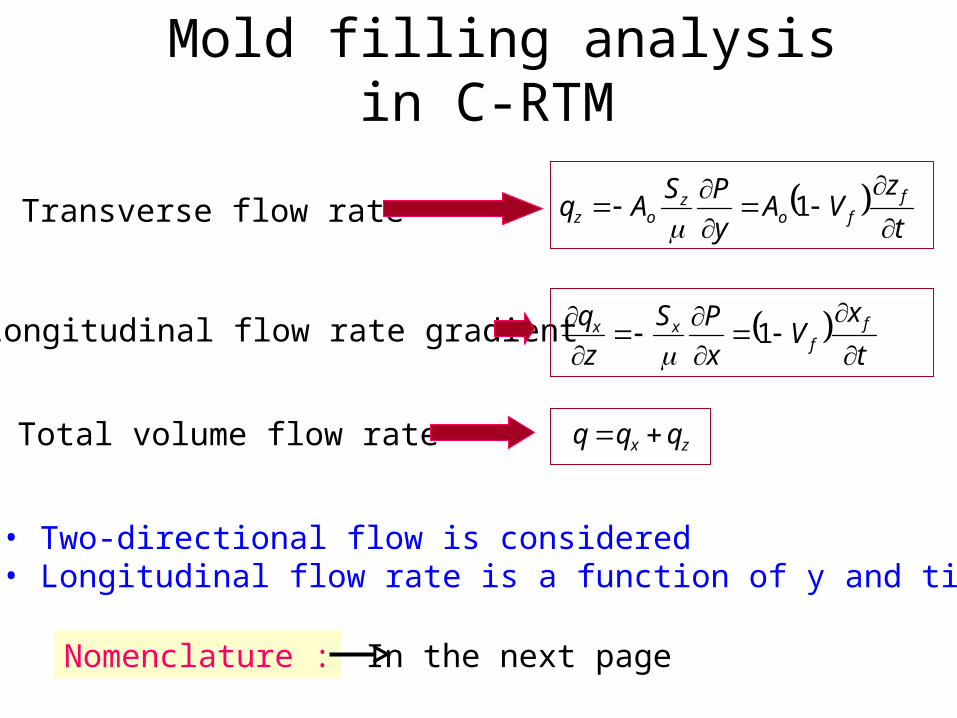
Mold filling analysis in C-RTM
Transverse flow rate
Longitudinal flow rate gradient
Total volume flow rate
t
zVA
y
PSAq f
foz
oz
1
t
xV
x
PS
z
q ff
xx
1
zx qqq
• Two-directional flow is considered• Longitudinal flow rate is a function of y and time
Nomenclature : In the next page
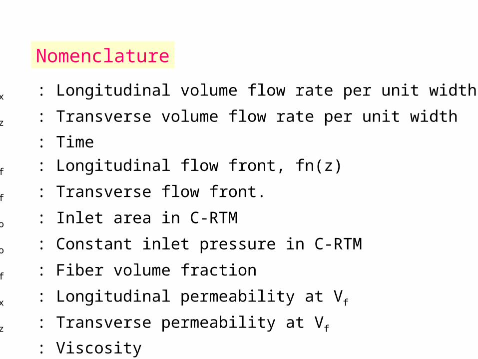
qx : Longitudinal volume flow rate per unit width
qz : Transverse volume flow rate per unit width
t : Time
xf : Longitudinal flow front, fn(z)
zf : Transverse flow front.
Ao : Inlet area in C-RTM
Po : Constant inlet pressure in C-RTM
Vf : Fiber volume fraction
Sx : Longitudinal permeability at Vf
Sz : Transverse permeability at Vf
: Viscosity
Nomenclature

Mold filling analysis in A-RTM
Resin flow in A-RTM Two-stage flow
Case 1 : Initial stage when the first segment is in motion
• Transverse down-flow through the loose preform only
• Longitudinal flow through the squeezed preform is restricted
Case 2 : After the transverse flow is completed in case 1.
• Longitudinal flow is driven by the excessive resin squeezed
by segment motion.
• Transverse flow is achieved by the consolidation
of the wet loose preform
ooz
oz V
tPSVAq
1
21
'
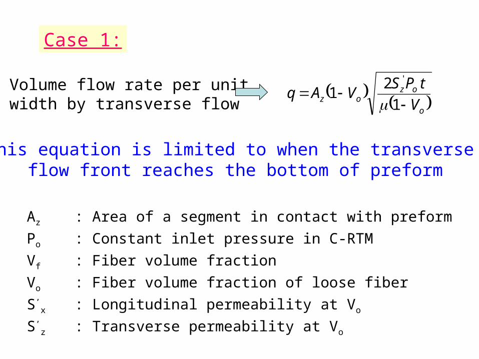
Case 1:
Volume flow rate per unit width by transverse flow
Az : Area of a segment in contact with preform
Po : Constant inlet pressure in C-RTM
Vf : Fiber volume fraction
Vo : Fiber volume fraction of loose fiber
S’x : Longitudinal permeability at Vo
S’z : Transverse permeability at Vo
This equation is limited to when the transverse flow front reaches the bottom of preform

Case 2:
Volume flow rate per unit width by longitudinal flow
After the transverse flow is completed in case 1
tc : Time when the transverse flow reaches bottom
(when hf = h’)
h’ : Preform thickness at Vo
S’x : Longitudinal permeability at Vo
S’z : Transverse permeability at Vo
112
3
122/3
1f
cfo
h
httD
hVq
oox
V
PSD
11 o
oz
V
PSD
12 o
ozf V
tPSh
1
2
where

Mold filling simulation results
Mold fill ratio with time
• tr : Mold-fill time
for C-RTM
• Po : Inlet pressure
for C-RTM
• P(segment load)=Po
• Ten segments0
0.2
0.4
0.6
0.8
1
0 0.2 0.4 0.6 0.8 1Normalized time (t/tr)
Mo
ld-f
ill
rati
o
Articulated process
Conventional RTM
Result: Mold fill time for A-RTM is 6 % of C-RTM fill time

Effect of segment load on mold fill time
• tr: Mold-fill time
for C-RTM
• P(segment load)=xPo
• Ten segments
• For P/Po = 1, mold fill time (t/tr)=0.06 relative to C-RTM
• Lower pressures than this still result in faster mold fill times relative to C-RTM
0
0.1
0.2
0.3
0.4
0.5
0 1 2 3 4 5Pressure (P/Po) for articulated process
Mo
ld f
ill
tim
e (t
/tr)

Effect of number of segments
• ts : Mold-fill time
for ten Segments
• P(segment load)=Ps
• Mold length is constant
• For ten segments, mold fill time (t/ts)=1.
• Four segments result in a 40% increase in mold fill time.• This is still only 8% of C-RTM mold fill time.
1
1.2
1.4
1.6
1.8
2
2 4 6 8 10Number of segments
Mo
ld f
ill
tim
e (t
/ts)
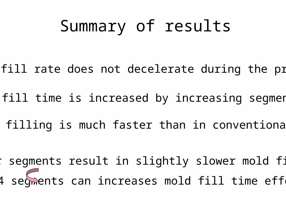
Summary of results
• Mold-fill rate does not decelerate during the process
• Mold fill time is increased by increasing segment load
• Fewer segments result in slightly slower mold filling
3-4 segments can increases mold fill time effectively
• Mold filling is much faster than in conventional RTM
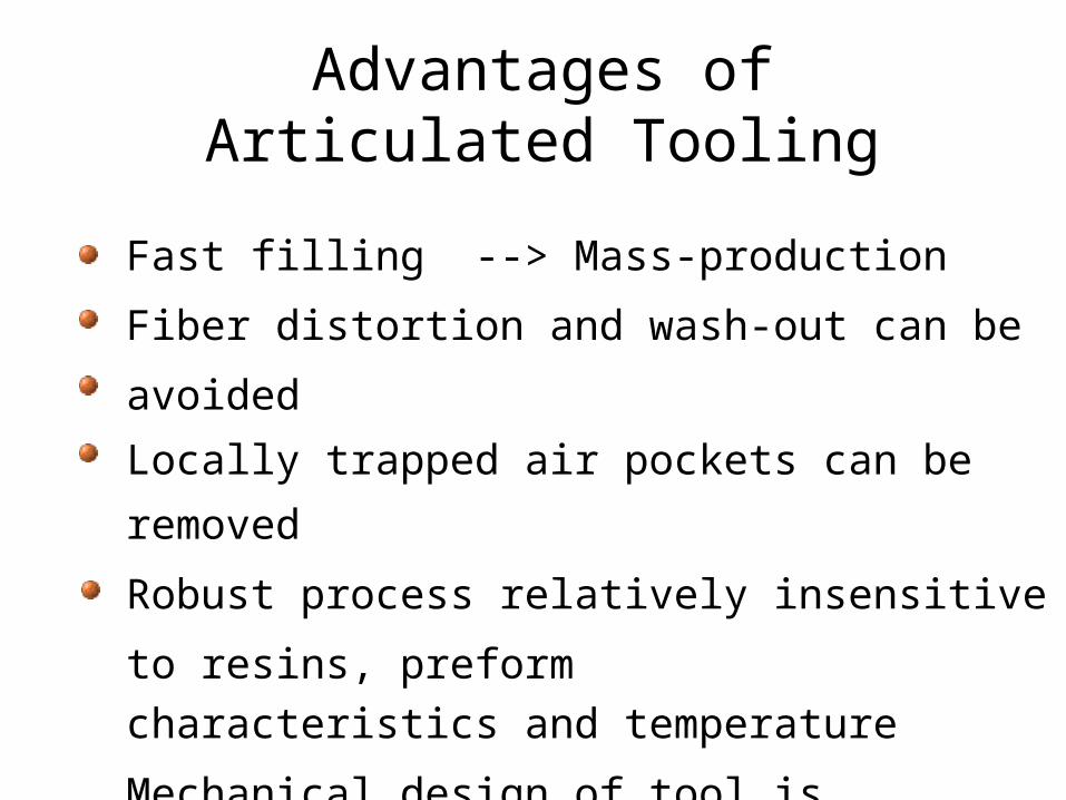
Advantages of Articulated Tooling
Fast filling --> Mass-production
Fiber distortion and wash-out can be avoided
Locally trapped air pockets can be removed
Robust process relatively insensitive to resins, preform
characteristics and temperature
Mechanical design of tool is complicated but probably
not significantly more than for a typical injection
molding tool
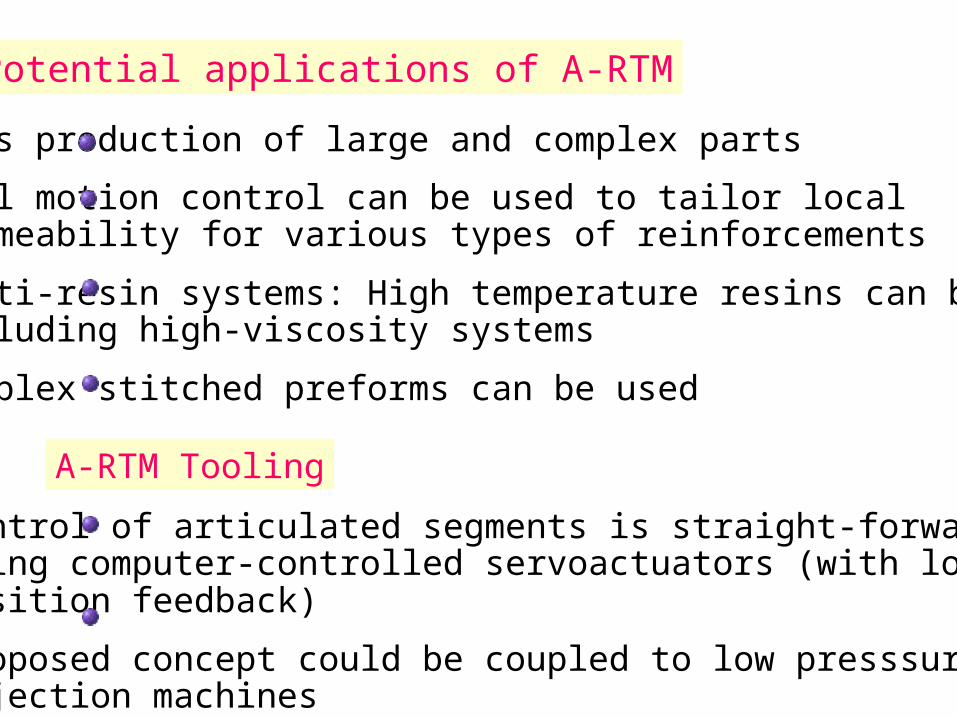
Control of articulated segments is straight-forward using computer-controlled servoactuators (with load andposition feedback)
Proposed concept could be coupled to low presssure injection machines
A-RTM Tooling
Mass production of large and complex parts
Tool motion control can be used to tailor local permeability for various types of reinforcements
Multi-resin systems: High temperature resins can be used,including high-viscosity systems
Complex stitched preforms can be used
Potential applications of A-RTM

Articulated RTM Tooling
Schematic of axi-symmetric process
Center piston(segment)
First ring(segment)
Second ring(segment)
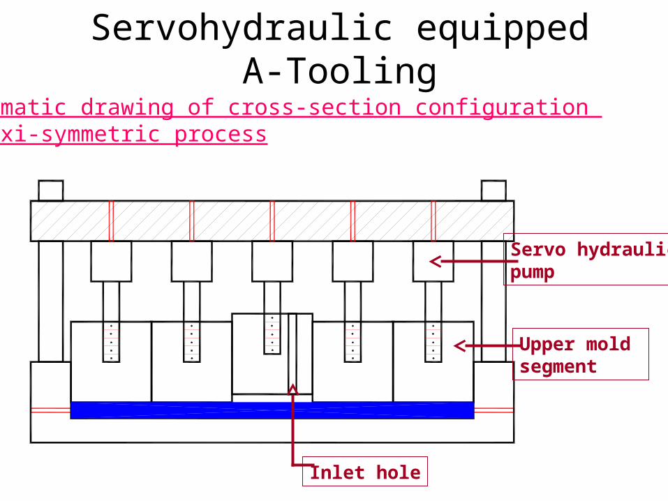
Servohydraulic equipped A-Tooling
Schematic drawing of cross-section configuration of axi-symmetric process
Servo hydraulicpump
Inlet hole
Upper mold segment
Drawbacks of Articulated Tooling
Expensive tooling
Probably restricted to small parts < 1 m2 ?
Potential for fiber damage by articulated segments needs to be assessed and eliminated by tool force control.

Future work
Conduct simple experiments using axisymmetric segmented mold
Study preform characteristics using preg fiber bundles for thermoplastic matrices.
Couple to front-end of injection
molding machine.
Issues to be addressed
• Modeling of conventional processes should predict defects and flow paths.
• Adjustments in conventional processes should be applied to eliminate predicted defects, increase process speed, widen range of allowable parameters (viscosity, molecular weight, temperature, reaction times).
• Transfer to industry via interactive programs (instrumented prototype machinery, correlation with models, validate improved processes)

Modeling issues
• Dynamic modeling• Pressure gradient-dependent permeability• Thermoplastic processing extension to
continuous, oriented fibers.• Controlled porosity, fiber orientation and
distribution achieved by mold and process design.
• Preform and fiber placement machine design.