Embed Size (px)
Citation preview

NSF - UCM - INTI - IADO - IPT
PASI-PASEO The Pan-American Sensors for Environmental
Observatories (PASEO) Workshop.
Mário Ricardo Gongora-RubioInstitute for Technological Research (IPT- São Paulo - Brazil)

OUTLINE
Microtechnology a Powerful ToolLTCC Technology & ProcessingBasic Design Rules LTCC DevicesFabrication Techniques for Microfluidic DevicesMicrofluidic Devices Lab on a PackageConclusions

NSF - UCM - INTI - IADO - IPT
PASI-PASEO The Pan-American Sensors for Environmental
Observatories (PASEO) Workshop.
MICROTECHNOLOGY A POWERFUL TOOL

WHAT IS MICROTECHNOLOGY?
Is an outstanding strategy for miniaturization and integration where the same principles as inmicroelectronics, are applied to Mechanical, Acoustic, Optical, Magnetic, Thermal, Chemical or Biotechnical components and systems.
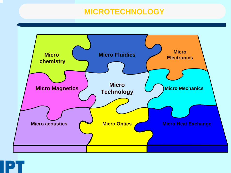
MICROTECHNOLOGY
MicroTechnology
Micro Fluidics MicroElectronics
Micro Magnetics
Micro chemistry
Micro Mechanics
Micro acoustics Micro Optics Micro Heat Exchange

NSF - UCM - INTI - IADO - IPT
PASI-PASEO The Pan-American Sensors for Environmental
Observatories (PASEO) Workshop.
LTCC TECHNOLOGY AND PROCESSING

CERAMIC INTERCONNECTION TECHNOLOGY
Source: Green Tape Application Group
PI-LTCC

COMPARISON OF HYBRID CERAMIC TECHNOLOGIES
Thick Film HTCCLTCCDisadvantages DisadvantagesAdvantages Advantages
- Multiple printing steps
- Multiple firings
- Thickness control of dielectric
- Limited layer count
- Low Conductivity Metals (W,Mo)
- Complex Process
- No printed resistors
- High Capital investment
- High conductivity metals (Au,Ag)
- Low Q Dielectrics
- Printed resistors
- Low processing temperature
- High print Resolution of condutors- Single firing- Good dielectric thickness control- Low surface roughness- Unlimited Layer count
Si TCE Match

WHAT IS LTCC ?
–LTCC was originally developed by Hughes and DuPont for Military Systems.
– The (LTCC) technology can be defined as a way to produce multilayercircuits with the help of single tapes, which are to be used to apply conductive, dielectric and / or resistive pastes on.
–These single sheets have to be laminated together and fired in one step all.
Multi Chip Module Bluetooth Interface (National)

LOW TEMPERATURE CO-FIRED CERAMICS (LTCC)
Glass-ceramic composite materialsThe ceramic filler is usually alumina, Al2O3
The usual composition also includes a glass frit and an organic binder (plasticizerand anti-flocculant)Called green tape before firing and sintering
LTCC-951 Composition
40%
45%
15%
Alumina
Glasses (Silicates)
Other Organics

Motorola
LTCC CERAMIC MICROSYSTEMS

Meso Meso
SystemSystem
ModuleModule
TECHNOLOGY VISION
ActuatorMicro
Fluidics
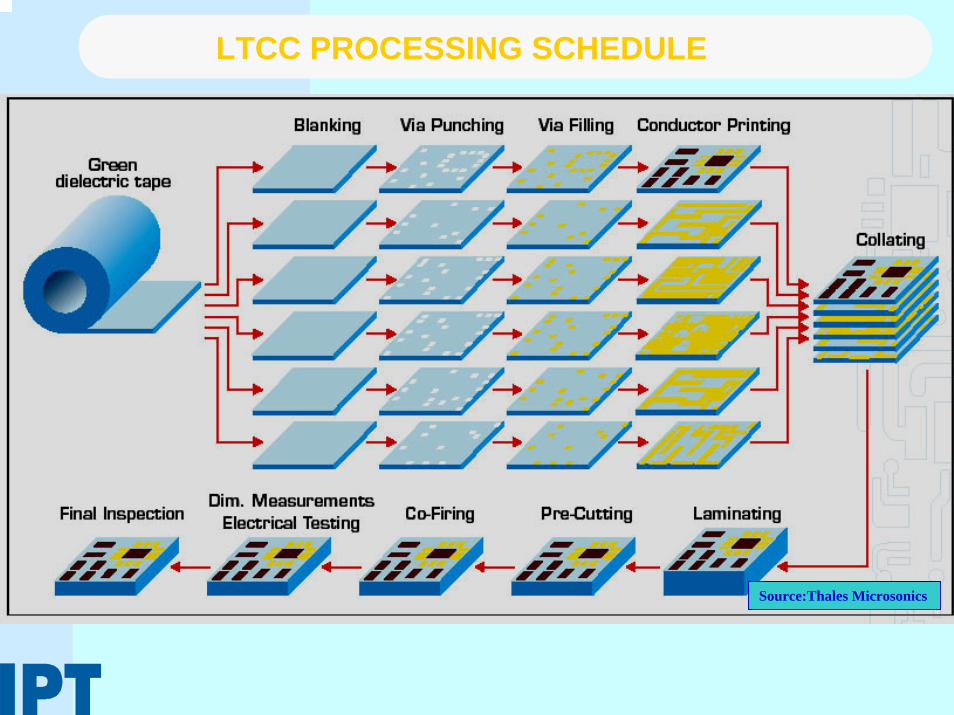
LTCC PROCESSING SCHEDULE
Source:Thales Microsonics

LTCC MANUFACTURING PROCESS (1)
Materials PreparationMaterials Preparation– LTCC Ceramic tape materials are
prepared by milling precise amounts of raw materials into a homogeneous slurry.
– This mixture is principally of ceramic/glass powders with controlled particle sizes with fluxes and small amounts of organic binders and solvents.
– This slurry is poured onto a carrier and then passed under a blade to produce a uniform strip of specific thickness.
– When dried, this strip becomes a ceramic-filled “Green ceramic tape” which is easily handled in rolls or sheets for unfired processing.
Ceramic Slurry
Doctor BladeHot Air
Mylar coil Green Ceramic coil
Base
Coil Movement System

LTCC MANUFACTURING PROCESS (2)
Tape PreparationTape Preparation– Cutting tape – Pre-Conditioning in the furnace – Punching or burning registration
holes – Removing Mylar-tape
BlankingBlanking–A blanking die is used to create orientation marks and the final working dimension of the green sheets.

LTCC MANUFACTURING PROCESS (3)
Via MachiningVia Machining– Using high-speed mechanical
punching with a matrix tool, Laser System, CNC or JVE.
Via FillingVia Filling– Performed using an thick film
screen printer with a stencil metal mask.
– Registration is performed using a vision system.

LTCC MANUFACTURING PROCESS (4)
Paste PrintingPaste Printing– Resistor, conductor and
dielectrics deposits are performed using an automatic thick film screen printer with mesh screens.
CollatingCollating– All layers will be collated and
stacked with a special tool and will be fixed together to avoid misalignment.
– Can be performed using a vision system for alignment.

LTCC MANUFACTURING PROCESS (5)
LaminatingLaminating– Accomplished using
uniaxial or isostaticlamination in a specially designed press.
– Typical cycle time is 10 minutes. The range of laminating pressure is from 200 to 300 bar.
PrePre--CuttingCutting– Laminates are pre-cut with
a hot blade, meeting the panel drawing specifications.

LTCC MANUFACTURING PROCESS (6)
CoCo--FiringFiring–Made in a belt or special furnace at a peak temperature of 850°C and a dwell time of 15 minutes.
–The typical cycle time is 3 hours.
glass
Alumina
glass
Alumina
Sintering Model
850
350
Temperature (oC)
Time (min)
45 min
30 min
Ramp = 10oC/min
LTCC Temperature profile
Sintering Furnace
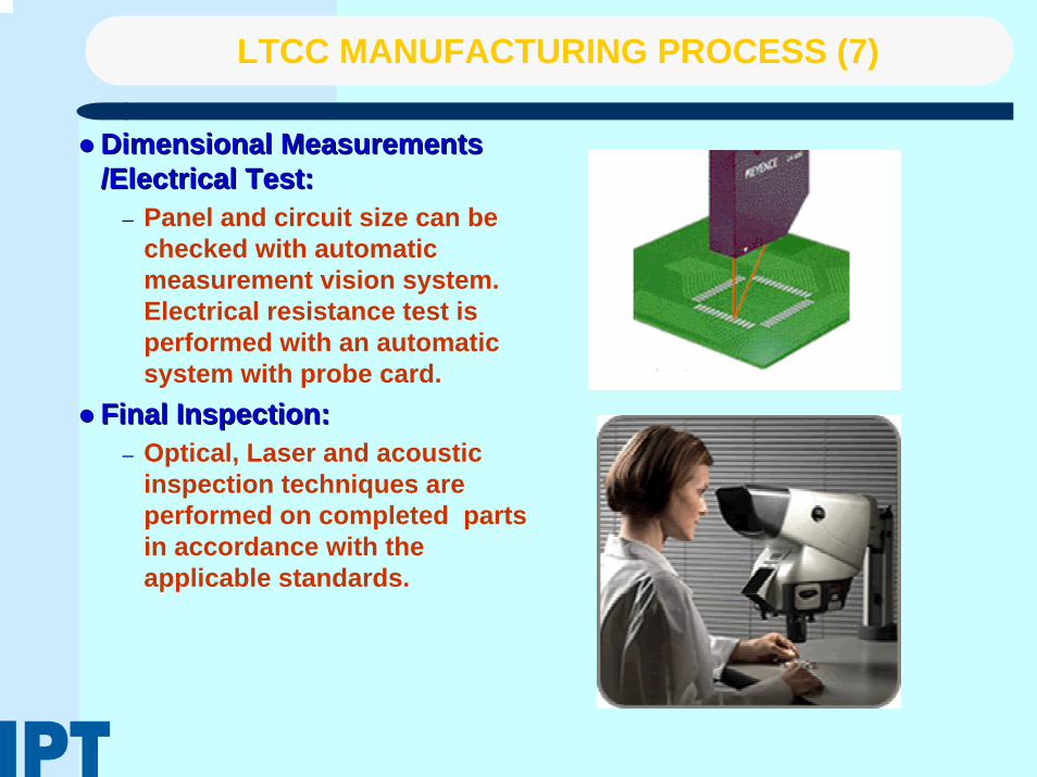
LTCC MANUFACTURING PROCESS (7)
Dimensional Measurements Dimensional Measurements /Electrical Test:/Electrical Test:
– Panel and circuit size can be checked with automatic measurement vision system. Electrical resistance test is performed with an automatic system with probe card.
Final Inspection:Final Inspection:– Optical, Laser and acoustic
inspection techniques are performed on completed parts in accordance with the applicable standards.

PUNCHINGPUNCHINGCircular or square shapeSmallest size 0.004”(~100microns)Machining of curved features is difficultPartial depth machining cannot be done
CNC MILLINGCNC MILLINGSmallest size 0.005”(~125microns)Machining of curved features is easy Partial depth penetration facilitating shallow channels and thin membranesVacuum chuck holder or wet tape is used to fix tape
Vacuum chuck holder for CNC milling
Punched curve
CNC milled curve(two layered structure; the curved slot is in the top layer only)
MilledPunched Tool
Partial depth CNC milling
MECHANICAL MACHINING OF CERAMIC TAPES

CO2, IR and CO2, IR and NdNd--YagYag LaserLaserThermal machining process
ExcimerExcimer LaserLaserSmallest size: ~10 micronsNo thermal damage (adiabatic process)Machining of whole feature at once using maskPartial depth penetration facilitating shallow channels and thin membranesSchematic of the Laser machined hole Schematic of the Laser machined hole
SideView
TopView
ExcimerExcimer Laser machined sampleLaser machined sample(~ 40 micron holes, 20X) (~ 40 micron holes, 20X)
NdNd--YagYag Laser machined sampleLaser machined sample( ~150 micron wide channel, 20X)( ~150 micron wide channel, 20X)
Yag Yag Laser Laser Machined Machined ViaVia
LASER MACHINING OF CERAMIC TAPES

LAMINATION ISSUES-THERMO-COMPRESSION
The most used method to conjoin stacked green tapes. It takes place at temperatures up to 100ºC and at pressures up to 3000 PSI.
– For microfluidic applications, the uncontrolled mass flow, which occurs during the application of high pressure, avoids the formation of fine and complex three-dimensional structures, such as channels for mixers and chambers or cavities for chemical reactions.
Channel deformation due to the thermo-compression process.Hellebrand`s Model

COLD LOW PRESSURE TECHNIQUE
In this technique, there is temporary gluing step of two adjacent green tapes using adouble-faced adhesive tape. The process works under very low pressure and atroom temperature, which minimizes deformations. Although before the sintering process the tapes are separated by the adhesive tape and the interpenetration ofparticles cannot occur, the tapes are, indeed, conjoined together homogeneously after sintering. In CLPL the joining mechanism is controlled by the chemistry of the double-sided adhesive tape and by its changes of the consistency and rheological behavior during the heat treatment.According to Roosen, the conjoining mechanism occurs due to the polymer meltingat much higher temperatures than the pure binder system of the green tape.
CLPL after Roosen

LOW TEMPERATURE AND PRESSURE LTCC LAMINATION USING ORGANIC FLUIDS
For Microfluidic applications, the uncontrolled mass flow, which takes place during the application of high pressure of thermocompression method prevents the formation of fine structures and complex three dimensional structures, such as channels for mixers and chambers for chemical reactions.A novel technique developed to conjoin different vitro-ceramic LTCC green tapes, is based on the utilization of viscous organic fluids.
–This technique consists of the deposition of a thin layer of an organic fluid upon green ceramic tape surface, by any means, to get a temporary gluing until sintering process is done. This temporary gluing process is realized at room temperature and at very low pressure.
Ceramic Green Tape
Lamination
Sintering
Organic Fluid Deposition
Ceramic Green Tape
Lamination
Sintering
Organic Fluid Deposition

Carbon Tape (Paste) Applications in LTCC
Carbon Tapes are used to form in-situ channels and cavities inlaminated ceramic structures(LTCC, HTCC). Thermally fugitive Carbon Tapes burn out cleanly in air atmospheres and begin torapidly sublimate at 600oC.
–Prevents deformation during lamination and slumping during firing of ceramic parts
–• Does not expand or melt during firing – sublimates directly without causing stress on green parts
–• Leaves no ash or residue after burnout
–• Useful as a separating medium and thermally fugitive mask
–• Tapes can be laminated, punched,sliced, machined or laser cut

SACRIFICIAL VOLUME TECHNIQUE
i - Thick film dielectric line on SVMii - Thick film conductor line on SVMiii- Conductor-on-conductor vias with
center support that is dielectriciv - Sacrificial volume area surrounded
by open area for unfired tape bondingv - Conductor bridging SVM plug on
ceramic tape to form diaphragm on firing
vi - Thick film dielectric line crossingSVM layer to form bridge suspended above substrate and crossing SVMplug to form bridge across gap in tape layer
vii - Thick film conductor line crossingSVM layer to form bridge suspended above substrate and crossing SVM plug to form bridge across gap in tape layer
viii - SVM line on top of ceramic tapelayer and on top of SVM via fill to form fluidic channel when laminated toanother ceramic tape and fired

SVM MICROCHANNEL FORMING TECHNIQUE
Sacrificial volume technique is used to create microchannels during lamination by deformation of the unfired tape.
Sandia Labs
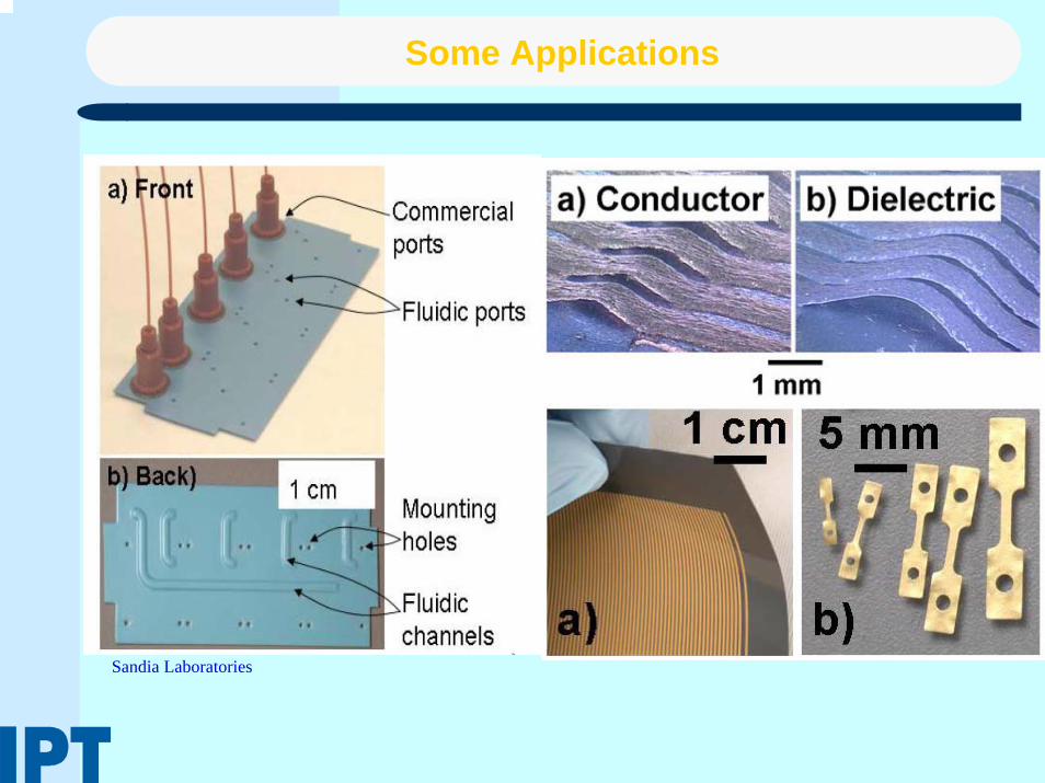
Some Applications
Sandia Laboratories

NSF - UCM - INTI - IADO - IPT
PASI-PASEO The Pan-American Sensors for Environmental
Observatories (PASEO) Workshop.
BASIC DESIGN RULES

LTCC WITH EMBBEDED PASSIVES
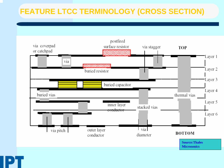
FEATURE LTCC TERMINOLOGY (CROSS SECTION)
Source:Thales Microsonics

FEATURE LTCC TERMINOLOGY (TOP VIEW)
Source:Thales Microsonics

DESIGN RULES (1) CONDUCTORS & RESISTORS
Source:Thales Microsonics

LTCC DESIGN RULES (2) VIAS
Source:Thales Microsonics
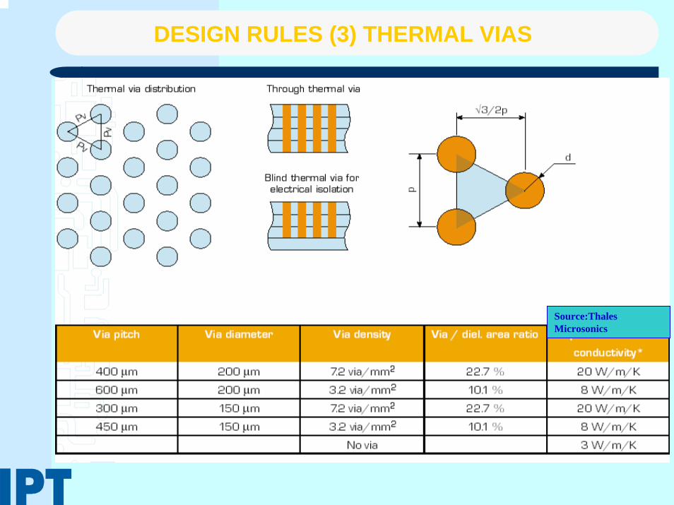
DESIGN RULES (3) THERMAL VIAS
Source:Thales Microsonics

DESIGN RULES (4) CAPACITORS & INDUCTORS
CapacitorsCapacitors
InductorsInductors
Source:Thales Microsonics

LTCC DESIGN RULES (5) CAVITIES
Source:Thales Microsonics

LTCC TOP LAYER & INNER LAYER CAVITIES

NSF - UCM - INTI - IADO - IPT
PASI-PASEO The Pan-American Sensors for Environmental
Observatories (PASEO) Workshop.
LTCC DEVICES

LTCC LOAD CELL
Applied Force
Metal Sphere
Piezoresistive Post
Upper Structure
Upper Structure Lower Structure
Operation for compressive forces offer direct force measurement and allow theuse of arrays for vectorial force decomposition, without mechanical translation.Force is applied through a metal sphere.Three posts at an angle of 120o to each other, connected to an upper structure,receive the decomposed force, each post sustain 1/3 of total applied force.

EXTERNAL ELECTRODES SENSOR IMPLEMENTATION
Applied ForceCavities
LTCC Metal contacts
Piezoresistive material Sacrifice material
L6
L5
L4
L3
L2
L1

EXTERNAL ELECTRODE SENSOR
Each post has a diameter of 950 µm and a 200 µm height.
Detail of 3D sensor using SPS, after removing upper sensor structure.
Detail of 3D sensor using SPS, after removing upper sensor structure.

LTCC FLOW SENSORS
A-A
Layer
Layer 2 Layer 3
Layer 4 Layer 5 Cross-section A-A
L1
L2
L3
L4
L5
Layer 1
Fabricated Device
0 1 2 3 420
25
30
35
40
45
50
Dissipation factor Vs. Flow velocity k = 18,79 + 31,03 * e(-vf / 1,66) for exponential regression
Diss
ipat
ion
Fact
or (W
att/K
elvin
)
Flow Velocity (SLM)
Experimental Set-Up
Device Lay-out

Gas Inlet Tube(brass)
(∅i 2.5mm)
Microcolumns(500μm x 500μm)
Upper Electrode (AgPd)(10 x10 mm2 x 30μm)
ContactTerminal
Interelectrodespacer (250μm)
Lower Electrode (AgPd)(10 x10 mm2 x 30μm)
Microchannels(∅200μm x 500μm)
9LTCC Layers
MICROPLASMA GENERATOR

POST-FIRE PROCESS USING TRANSFER TAPES

Argon microplasma:3.8 Torr, 50 sccm, 6 mA
Oxygen microplasma:3.8 Torr, 100 sccm, 8 mA
Stable and uniform DC microplasma were obtained.
RESULTS

DEVICE APPLICATIONS
The fabricated device can be used for surface treatment applications, in this case we modify surface of a polyethylene (PE) film in order to render a hydrophylicsurface, changing the water contact angle of surface.
PE film treated by N2 microplasma at 14 Torr, 30 sccm and 10 mA (DC).
0
20
40
60
80
100
0 10 20 30 40 50 60
Time (s)
Wat
er c
onta
ct a
ngle
(deg
ree)
.
Untreated sample

LTCC HEAT EXCHANGER

NSF - UCM - INTI - IADO - IPT
PASI-PASEO The Pan-American Sensors for Environmental
Observatories (PASEO) Workshop.
FABRICATION TECHNIQUES FOR MICROFLUIDIC DEVICES

MICROFLUIDICS DIMENSIONS

LTCC MANIFOLDS FOR MICROFLUIDICS

MICROCHANNELS
Poiseuille equation relates linearly pressure drop with flow in reduced geometry channels.
A A
Corte A-A
A A
A A
1mm
In microchannels of minute dimensions Reynolds Number are very low, making difficult liquid mixing.
Microchannel corners can be used as mixers.
Channel machining using CNC with features of 200 micrometers are possible.

LTCC HOT EMBOSSING
Small features can be transferred to LTCC layers using Hot Embossing TechniqueSeveral Molds for complex structures have been constructedDevelopment of the technique is in progress
Hot Embossing Mold for Pre-Concentrator

LTCC STRUCTURES FOR MICROFILTERING
Need to integrate aMicrofiltering stage intoLTCC Microfluidic systemPossibility of create structures for Catalyticmaterial deposition for Fuel Cells or chemical reactionsPossibility of creating high area for biological seeds.
Ceramic Porous Membranes
LTCC
LTCC
LTCC

POROUS LTCC & THICK FILM
200 μm

NSF - UCM - INTI - IADO - IPT
PASI-PASEO The Pan-American Sensors for Environmental
Observatories (PASEO) Workshop.
MICROFLUIDIC DEVICES

SPECTRUM OF MICROFLUIDICS APPLICATIONS
Fluid management SystemsMicro Analytical SystemsMicro Reaction SystemsMicro Heat exchange systems

3D MICROMIXERS IN LTCC
3D Micromixers can be used to accomplish Chemical Reactions, and for generating micro and particles for drug delivery
10 mm

MEMBRANE EMULSIFICATION

CONTINUOUS PARTICLE SEPARATION

SPLIT FLOW THIN FRACTIONATION

CO-PRECIPITATION PROCESS

Vortex Mixer

Ultrasonic + Vortex Mixer Crystallization

NSF - UCM - INTI - IADO - IPT
PASI-PASEO The Pan-American Sensors for Environmental
Observatories (PASEO) Workshop.
LAB ON A PACKAGE

Source: Caliper
• separation• dilution• mixing and dispensing• analysis
LAB-ON-A-CHIP SYSTEMS
Can integrate functions as:

MICROFLUIDIC BIOCHIPS
Integrate all necessary functions for biochemical analysis into one chip using microfluidics technology. Continuous-flow microfluidics vs. digital microfluidics
(University of Michigan) 1998
(Duke University) 2002
Mixed dropletElectrical pad
Electrowettingelectrode
LED Mixing sample & reagent
Photodiode

LTCC APPLICATIONS FOR MICROFLUIDICS
Technical University of Dresden

MST APPLICATIONS: PCR IN CONTINUOUS FLOW
Integrated microfluidic devices for PCR amplification and detection of biological samples that employ closed-looptemperature monitoring and control have been demonstrated within a multilayer low temperature co-fired ceramics (LTCC)platform.
Motorola Labs

SERIAL DILUTION IN LTCC
Serial Dilution device
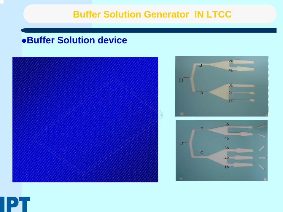
Buffer Solution Generator IN LTCC
Buffer Solution device
5a B 4a T1 3a
A 2a
1a
5b D 4b T2 3b C 2b 1b
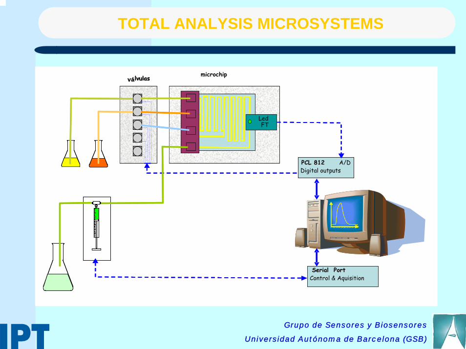
LedFT
A/DSalidas digitalesPCL 812
Puerto serie
válvulas microchip
Ordenes y respuestas
LedFT
A/DDigital outputsPCL 812
Serial Port
válvulas
Control & Aquisition
Grupo de Sensores y Biosensores
Universidad Autónoma de Barcelona (GSB)
TOTAL ANALYSIS MICROSYSTEMS

CHLORIDE ION WITH POTENTIOMETRIC DETECTION
[Cl-] (ppm)
1 10 100 1000
Pea
k he
ight
(mV
)
0
20
40
60
80
100
120
140
Time (s)
0 20 40 60 80 100 120 140 160 180
Pote
ntia
l (m
V)
-260
-240
-220
-200
-180
-160
-140
-1205ppm
10ppm
20ppm
40ppm
50ppm
80ppm
100ppm
200ppm
250ppm
500ppm
DiskAg2S/AgCl
Cable
Sample Cl- (ppm)CE
Cl- (ppm)LTCC (n=3, 95%)
S1 12 16±2
S2 7 11.5±0.8
S3 14 17±2
S4 22.8 26±2
S5 33.2 31.2±0.8
S6 603 599±70
Paired t test tcal=1.065, ttab=2.571 tcal<ttab No
Linear regressionLTCC vs CE
Interception:3±3Slope:0.99±0.01 r2=0.9999
No
TOTAL ANALYSIS MICROSYSTEMS

NITRITE ION ANALYZER WITH COLORIMETRIC DETECTION
2.2cm
2.6c
m
LTCC Device
OpticalWindow Imagen RX
Time (s)
0 20 40 60 80 100 120 140 160 180
Abso
rban
ce
-0,1
0,0
0,1
0,2
0,3
0,4
0,5
0,6
0.1ppm0.5ppm1ppm2ppm5ppm7ppm10ppm
[NO2-] (ppm)
0 2 4 6 8 10 12
AB
SOR
BAN
CIA
0.0
0.5
1.0
1.5
2.0
2.5
Q=5.83µl/svolumen muestra y reactivo=29µlRango 0.1-10ppmr2=0.9959
Abs=-3.31·10-3+0.048·[NITRITO]
Grupo de Sensores y Biosensores
Universidad Autónoma de Barcelona (GSB)
TOTAL ANALYSIS MICROSYSTEMS

Thanks for Thanks for your attention !your attention !

Micro Electronics
Pentium 4-–Top speed – 3.4ghz–Built on a 0.13 micron die
–168 million transistors on 200mm2

Micro - Optics
Ability to drill to ½ micron for half the wavelengthMicromirrors for next generation telescope optics
Micromirrors
Microlens Arrays

Micro - Chemical
Miniature fuel cellsMicro channelsChemical reactors
50 Micron Chemical Reactor
Micro Chemical Channel
Micro Fuel Cell
Microcytometer

Micro Acoustics
ultrasonic Mixer / piezoelectric vibrations (actuated membrane)
Principle:- traveling waves (produced by complex integrated structures)- mixing of aqueous / non-aqueous

Important components:
- Micro channel
- Electrokinetic (EK) pumps
Closed loop system
Two-phase system
Impinging cooling
Microchannel Heat Exchanger

Micro Magnetics
Biosampling and Immunoassay procedure using magnetic bead approach

Micro Mechanics
World’s smallest steam engine, the pistons are 5 microns
and it actually works
Micro Clutch mechanism, gears are 50 microns

Microfluidics
Capillary uptakePiezoelectric inkjetsFlow sensingDrug dispensingFlow based separation
Print Cartridges
Lab-On-Chip for DNADetection and Analysis
Micro Channels
• Molecules with largediffusion coefficientscan be extracted fromthose with small diffusion coefficients.