Embed Size (px)
Citation preview

NSE IS 05.02.2010 Page 1
CEAG V-CG-SB new DALI interface module
Lighting Management System
D A L I
11.2

NSE IS 05.02.2010 Page 2
CEAG V-CG-SB new DALI interface module
The CEAG and DALI interface solution
New CEAG V-CG-SB module for connection between CEAG EML systems with STAR technology and electronic ballast with DALI functionality.
V-CG-SB
Dimensions (L x W x H): 145 x 30 x 21 mmOrder - No. 400 71 352 442 (single packing)
Replacement of: 2L-CG-SB
V-CG-SB
Dimensions (L x W x H): 145 x 30 x 21 mmOrder - No. 400 71 352 442 (single packing)
Replacement of: 2L-CG-SB
NSE IS 05.02.2010 Page 3
CEAG V-CG-SB new DALI interface module
Monitoring module for function monitoring of lamps with DALI ECG
21
External DALI - controller
230V
SDB-M
Switch-/dimming unit
e.g. day light sensor
DA
LI B
us
max. 1m!
incl. DALI ECG
incl. DALI ECG
incl. DALI ECG
ENEC approval submitted
NSE IS 05.02.2010 Page 4
CEAG V-CG-SB new DALI interface module
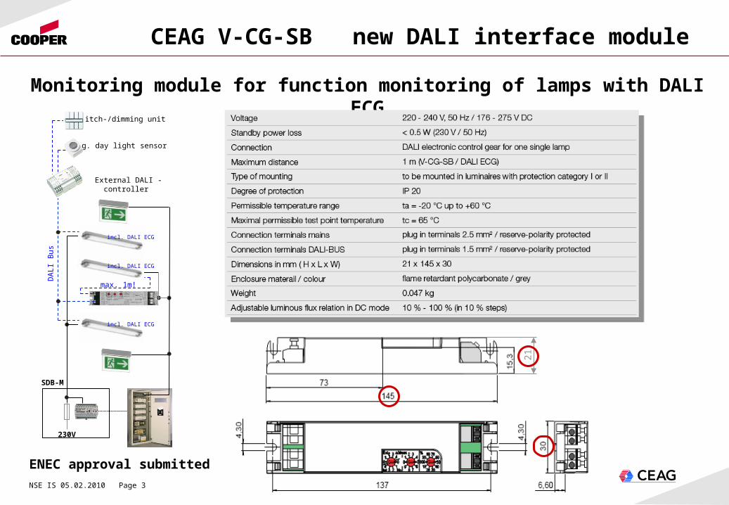
Description of CEAG new V-CG-SB module
Power supply by
ZB-S or CG2000
Input external DALI-Bus D1, D2
Output externalDALI-Bus D1´, D2´ to the DALI ballast
Third switch is for the adjustable lightoutput level in DC Battery operation value 10% to 100% (in 10% steps)
First address switch (decade) Generally 2 different applications are possible for the use of the module 2L CG-SB. a) Standard application with an external DALI-Controller connected (Extern - right 0, 1, 2) b) Special application without an external DALI-Controller connected (Intern - left 0, 1, 2) One of these applications must be selected with the left address switch, which is in combination also used for setting the decade address 0 or 10 or 20 (plus the single address x of the right single address switch).
Second address switch (single)Switch for addressing the single address 1 to address 9 (0 = without monitoring)
L (+)
N (-)
NSE IS 05.02.2010 Page 5
CEAG V-CG-SB new DALI interface module
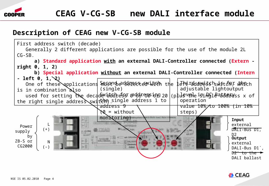
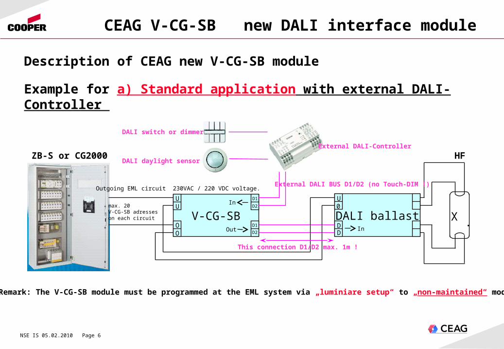
a) Standard application with external DALI-Controller
With the V-CG-SB module in Standard application the individual luminaire monitoring and the control of DALI electronic ballast of different suppliers is possible!
Operation modes with Emergency lighting systems are
1. Normal operation mode:- the brightness of the lamp is dimmed by the external DALI controller- the luminaire can be switched to 100% with CG-S function (e.g. for services)
2. Emergency operation in AC mode:- light output 100% independent of the external dimming controller and the settings at the V-CG-SB
3. Emergency operation in DC mode:- the external dimming controller will be without function, the electronic ballast will be dimmed to the chosen DC dimmlevel of the V-CG-SB (10 to 100% in 10% steps).
Description of CEAG new V-CG-SB module
NSE IS 05.02.2010 Page 6
CEAG V-CG-SB new DALI interface module
ZB-S
DALI ballast0
D
U
D
V-CG-SBU
O
U D1
D2
OD1
D2
DALI switch or dimmer
DALI daylight sensor
External DALI-Controller
ZB-S or CG2000
X .
max. 20 V-CG-SB adresses on each circuit
This connection D1/D2 max. 1m !
Description of CEAG new V-CG-SB module
Example for a) Standard application with external DALI-Controller
External DALI BUS D1/D2 (no Touch-DIM !)
Remark: The V-CG-SB module must be programmed at the EML system via „luminiare setup“ to „non-maintained“ mode !
Outgoing EML circuit 230VAC / 220 VDC voltage.
HF
Out
In
In

NSE IS 05.02.2010 Page 7
CEAG V-CG-SB new DALI interface module
1. Normal operation mode:- Function like a normal V-CG-S- DALI electronic ballast can be switched to ON (100%) or OFF (0%) with CG-S function
2. Emergency operation in ACmode:- light output 100%
3. Emergency operation in DC mode: - the DALI electronic ballast will be dimmed to the chosen dimmlevel of the CEAG V-CG-SB (10 to 100% in 10% steps).
Description of CEAG new V-CG-SB module
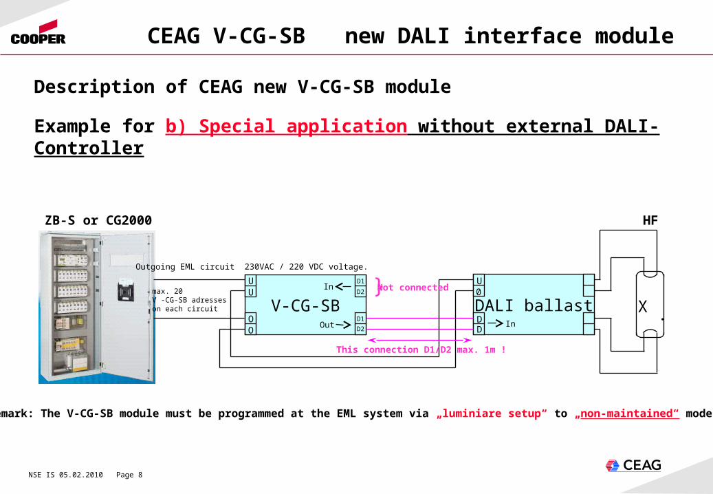
b) Special application without external DALI-Controller
With the V-CG-S module in this special application it is possible to use and to monitor DALI electronic ballast like usual electronic ballast, but with a reduced lightoutput in DC emergency operation.
Operation modes with Emergency lighting systems are
NSE IS 05.02.2010 Page 8
CEAG V-CG-SB new DALI interface module
Description of CEAG new V-CG-SB module
Example for b) Special application without external DALI-Controller
ZB-S
DALI ballast0U
V-CG-SBU
O
U D1
D2
OD1
D2
ZB-S or CG2000
X .
max. 20 V -CG-SB adresses on each circuit
This connection D1/D2 max. 1m !
Remark: The V-CG-SB module must be programmed at the EML system via „luminiare setup“ to „non-maintained“ mode !
Outgoing EML circuit 230VAC / 220 VDC voltage.
}Not connected
HF
Out
In
InDD

NSE IS 05.02.2010 Page 9
CEAG V-CG-SB new DALI interface module
HF
tube
L (U)
PEN (0)
External DALI BUS connection D1/D2 - only if required !If required than turn switch to standard application with „Extern“ (see page 4, 5 and 6)If not required - than turn switch to special application with „Intern“ (see page 4, 7 and 8)
Attention - no 230VAC Touch-DIM connection allowed !
This DALI connection D1/D2 must be wired. Distance maximum 1m ! (as short as possible)Separated from HF wiring !
HF wiring must be separated from other internal wiring. Do not misplace parallel with other internal wiring !Crossing with other wiring only in 90° angle.
If the electronic DALI ballast requires a PE or a functional earth, this must be connected, otherwise EMC problems could arise.
Incoming connection 230 VAC or 220 VDC to the circuit of the emergecy lighting system ZB-S.
DALI ballast
Description of mounting CEAG V-CG-SB module
Take care of the max. allowed temperature (TC points) for the DALI ballast and the V-CG-SB.
D1/D2Input

NSE IS 05.02.2010 Page 10
CEAG V-CG-SB new DALI interface module
1. Fix the DALI electronic ballast inside the luminaire housing 2. Fix the CEAG V-CG-SB DALI Interface module inside the luminaire housing Take care that the distance between the OUTPUT V-CG-SB and the INPUT DALI ballast is rational 3. Chose one of the operating modes with the first address switch Standard application “Extern” or Special application “Intern” 4. Fix the required address out of the combination of address switch one (decade) and address switch two (single) For example: address switch one “Intern 1” plus address switch two “7” => result address “17” Remark the different fixed addresses visible at the luminaire housing. 5. Fix the desired light level in DC emergency operation at switch three between 10 to 100% 6. Connect the power wiring L, N, PE to the V-CG-SB and the DALI ballast. 7. Connect the DALI Bus wiring between V-CG-SB and DALI ballast as short as possible. Maximum distance is 1m. Connect external DALI Bus wiring if required (no 230V Touch DIM allowed). 8. Connect the HF wiring to the lamp sockets as short as possible. Take care that the HF wiring is not parallel to other internal wiring. Crossing only in 90° angle. 9. Take care that the internal operation temperature at the Tc points of the electronic DALI ballast and the V-CG-SB module is not higher than specified. 10.Provide your complete luminaire with CE confirmation.
Ten mounting steps
NSE IS 05.02.2010 Page 11
CEAG V-CG-SB new DALI interface module
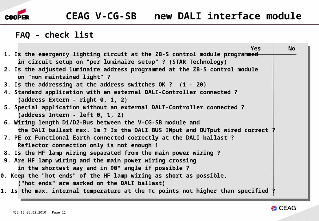
1. Is the emergency lighting circuit at the ZB-S control module programmed in circuit setup on "per luminaire setup" ? (STAR Technology) 2. Is the adjusted luminaire address programmed at the ZB-S control module on "non maintained light" ? 3. Is the addressing at the address switches OK ? (1 - 20) 4. Standard application with an external DALI-Controller connected ? (address Extern - right 0, 1, 2) 5. Special application without an external DALI-Controller connected ? (address Intern - left 0, 1, 2) 6. Wiring length D1/D2-Bus between the V-CG-SB module and the DALI ballast max. 1m ? Is the DALI BUS INput and OUTput wired correct ? 7. PE or Functional Earth connected correctly at the DALI ballast ? Reflector connection only is not enough ! 8. Is the HF lamp wiring separated from the main power wiring ? 9. Are HF lamp wiring and the main power wiring crossing in the shortest way and in 90° angle if possible ?10. Keep the "hot ends" of the HF lamp wiring as short as possible. ("hot ends" are marked on the DALI ballast)11. Is the max. internal temperature at the Tc points not higher than specified ?
FAQ – check list
Yes No

NSE IS 05.02.2010 Page 12
CEAG V-CG-SB new DALI interface module
• Low operating costs due to decreased standby losses < 0,5 W.• Minimize dimensions on the basis of the conventional T5 ECG cross section
(H x W: 21 x 30 mm) for an eased mounting in narrow luminaires.• Without protective conductor connection. For the use in luminaires with insulation class I or
II.• Variable mounting possibilities for different mounting positions (horizontal or sidewise
upright).• Avoidance of installation failures due to a mains connection being protected against polarity
reversal.• Universal monitoring module for all single DALI electronic control gears.• Shortened inspection effort due to CEWA GUARD Technology. Automatic function monitoring
of up to 20 luminaires per circuit.• Reduced installation costs due to STAR – Technology. Freely programmable mixed operation
of the switching modes per luminaire in one circuit.• Reduced installation expenditures as no additional data line to the luminaires is needed.• Enlarged ambient temperature range: Ta: -20°C up to +60°C. max. permissible test point temperature: Tc = 65°C.• Safe galvanic isolation of the bus systems (emergency / mains lighting during emergency
operation) acc. E DIN VDE 0108-100.• Adjustable luminous flux relation in DC mode in steps between 10% and 100%.
Characteristic / Advantage / Benefit

NSE IS 05.02.2010 Page 13
CEAG V-CG-SB new DALI interface module
• EN 61347-1: Lamp control gear• Part 1: General and safety requirements • EN 61347-2-11: Lamp control gear Part 2-11: Particular requirements for
miscellaneous electronic circuits used with luminaires• EN 60929 Appendix E (normative): Control interface for dimming ECGs
Suitable to be mounted in luminaires according:
• EN 60598-2-22: Luminaires. Part 2-22: Particular requirements .• Luminaires for emergency lighting
• and for the operation in emergency lighting systems according:
• DIN VDE 0100-718: Erection of low-voltage installations.• Requirements for special installations or locations.• Part 718: Installations for gathering of people• EN 50172: Emergency escape lighting systems• E DIN VDE 0108-100: Emergency escape lighting systems
Engineering standards
NSE IS 05.02.2010 Page 14
CEAG V-CG-SB new DALI interface module
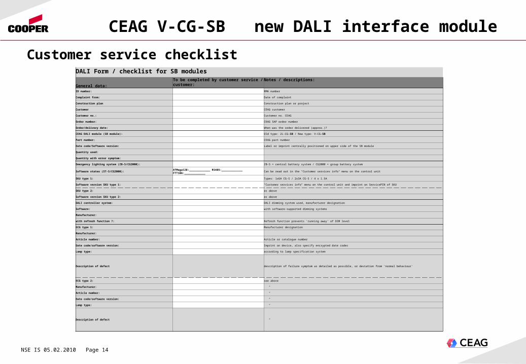
Customer service checklistDALI Form / checklist for SB modules
General data:
To be completed by customer service / customer:
Notes / descriptions:
ID number: RMA number
Complaint from: Date of complaint
Construction plan Construction plan or project
Customer CEAG customer
Customer no.: Customer no. CEAG
Order number: CEAG SAP order number
Order/delivery date: When was the order delivered (approx.)?
CEAG DALI module (SB module): Old type: 2L-CG-SB / New type: V-CG-SB
Part number: CEAG part number
Date code/Software version: Label or imprint centrally positioned on upper side of the SB module
Quantity used:
Quantity with error symptom:
Emergency lighting system (ZB-S/CG2000): ZB-S = central battery system / CG2000 = group battery system
Software states (ST-S/CG2000): ATMega128:_____________ RS485:_____________ FTT10A:_____________ Can be read out in the "Customer services info" menu on the control unit
SKU type 1: Types: 1x6A CG-S / 2x3A CG-S / 4 x 1.5A
Software version SKU type 1: "Customer services info" menu on the control unit and imprint on ServicePIN of SKU
SKU type 2: as above
Software version SKU type 2: as above
DALI controller system: DALI dimming system used, manufacturer designation
Software: with software-supported dimming systems
Manufacturer:
with refresh function ?: Refresh function prevents 'running away' of DIM level
ECG type 1: Manufacturer designation
Manufacturer:
Article number: Article or catalogue number
Date code/software version: Imprint on device, also specify encrypted date codes
Lamp type: according to lamp specification system
Description of defect description of failure symptom as detailed as possible, or deviation from 'normal behaviour'
ECG type 2: see above
Manufacturer: "
Article number: "
Date code/software version: "
Lamp type: "
Description of defect "
NSE IS 05.02.2010 Page 15
CEAG V-CG-SB new DALI interface module
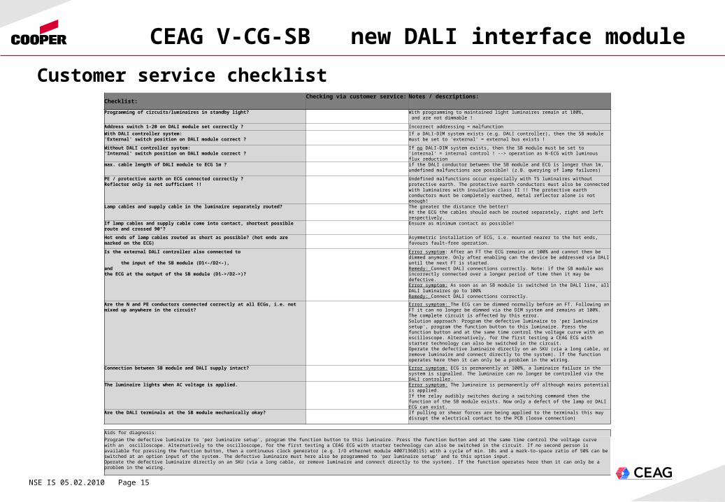
Customer service checklistChecklist:
Checking via customer service: Notes / descriptions:
Programming of circuits/luminaires in standby light? With programming to maintained light luminaires remain at 100%, and are not dimmable !
Address switch 1-20 on DALI module set correctly ? Incorrect addressing = malfunction
With DALI controller system:'External' switch position on DALI module correct ?
If a DALI-DIM system exists (e.g. DALI controller), then the SB module must be set to 'external' = external bus exists !
Without DALI controller system:'Internal' switch position on DALI module correct ?
If no DALI-DIM system exists, then the SB module must be set to 'internal' = internal control ! --> operation as N-ECG with luminous flux reduction
max. cable length of DALI module to ECG 1m ? if the DALI conductor between the SB module and ECG is longer than 1m, undefined malfunctions are possible! (z.B. querying of lamp failures)
PE / protective earth on ECG connected correctly ?Reflector only is not sufficient !!
Undefined malfunctions occur especially with T5 luminaires without protective earth. The protective earth conductors must also be connected with luminaires with insulation class II !! The protective earth conductors must be completely earthed, metal reflector alone is not enough!
Lamp cables and supply cable in the luminaire separately routed? The greater the distance the better! At the ECG the cables should each be routed separately, right and left respectively.
If lamp cables and supply cable come into contact, shortest possible route and crossed 90°? Ensure as minimum contact as possible!
Hot ends of lamp cables routed as short as possible? (hot ends are marked on the ECG) Asymmetric installation of ECG, i.e. mounted nearer to the hot ends, favours fault-free operation.
Is the external DALI controller also connected to the input of the SB module (D1<-/D2<-),and the ECG at the output of the SB module (D1->/D2->)?
Error symptom: After an FT the ECG remains at 100% and cannot then be dimmed anymore. Only after enabling can the device be addressed via DALI until the next FT is started.Remedy: Connect DALI connections correctly. Note: if the SB module was incorrectly connected over a longer period of time then it may be defective.
Error symptom: As soon as an SB module is switched in the DALI line, all DALI luminaires go to 100%Remedy: Connect DALI connections correctly.
Are the N and PE conductors connected correctly at all ECGs, i.e. not mixed up anywhere in the circuit? Error symptom: The ECG can be dimmed normally before an FT. Following an FT it can no longer be dimmed via the DIM system and remains at 100%. The complete circuit is affected by this error.Solution approach: Program the defective luminaire to 'per luminaire setup', program the function button to this luminaire. Press the function button and at the same time control the voltage curve with an oscilloscope. Alternatively, for the first testing a CEAG ECG with starter technology can also be switched in the circuit.Operate the defective luminaire directly on an SKU (via a long cable, or remove luminaire and connect directly to the system). If the function operates here then it can only be a problem in the wiring.
Connection between SB module and DALI supply intact? Error symptom: ECG is permanently at 100%, a luminaire failure in the system is signalled. The luminaire can no longer be controlled via the DALI controller.
The luminaire lights when AC voltage is applied. Error symptom: The luminaire is permanently off although mains potential is applied.If the relay audibly switches during a switching command then the function of the SB module exists. Now only a defect of the lamp or DALI ECG can exist.
Are the DALI terminals at the SB module mechanically okay? If pulling or shear forces are being applied to the terminals this may disrupt the electrical contact to the PCB (loose connection)
Aids for diagnosis:
Program the defective luminaire to 'per luminaire setup', program the function button to this luminaire. Press the function button and at the same time control the voltage curve with an oscilloscope. Alternatively to the oscilloscope, for the first testing a CEAG ECG with starter technology can also be switched in the circuit. If no second person is available for pressing the function button, then a continuous clock generator (e.g. I/O ethernet module 40071360115) with a cycle of min. 10s and a mark-to-space ratio of 50% can be switched at an option input of the system. The defective luminaire must here also be programmed to 'per luminaire setup' and to this option input.Operate the defective luminaire directly on an SKU (via a long cable, or remove luminaire and connect directly to the system). If the function operates here then it can only be a problem in the wiring.