Embed Size (px)
Citation preview
Citrix NetScaler Administration Guide
Citrix® NetScaler® 9.3
Copyright and Trademark Notice© CITRIX SYSTEMS, INC., 2011. ALL RIGHTS RESERVED. NO PART OF THIS DOCUMENT MAY BEREPRODUCED OR TRANSMITTED IN ANY FORM OR BY ANY MEANS OR USED TO MAKE DERIVATIVE WORK(SUCH AS TRANSLATION, TRANSFORMATION, OR ADAPTATION) WITHOUT THE EXPRESS WRITTENPERMISSION OF CITRIX SYSTEMS, INC.
ALTHOUGH THE MATERIAL PRESENTED IN THIS DOCUMENT IS BELIEVED TO BE ACCURATE, IT ISPRESENTED WITHOUT WARRANTY OF ANY KIND, EXPRESS OR IMPLIED. USERS MUST TAKE ALLRESPONSIBILITY FOR THE USE OR APPLICATION OF THE PRODUCT(S) DESCRIBED IN THIS MANUAL.
CITRIX SYSTEMS, INC. OR ITS SUPPLIERS DO NOT ASSUME ANY LIABILITY THAT MAY OCCUR DUE TO THEUSE OR APPLICATION OF THE PRODUCT(S) DESCRIBED IN THIS DOCUMENT. INFORMATION IN THISDOCUMENT IS SUBJECT TO CHANGE WITHOUT NOTICE. COMPANIES, NAMES, AND DATA USED INEXAMPLES ARE FICTITIOUS UNLESS OTHERWISE NOTED.
The following information is for FCC compliance of Class A devices: This equipment has been tested and found tocomply with the limits for a Class A digital device, pursuant to part 15 of the FCC rules. These limits are designed toprovide reasonable protection against harmful interference when the equipment is operated in a commercialenvironment. This equipment generates, uses, and can radiate radio-frequency energy and, if not installed and used inaccordance with the instruction manual, may cause harmful interference to radio communications. Operation of thisequipment in a residential area is likely to cause harmful interference, in which case users will be required to correct theinterference at their own expense.
Modifying the equipment without Citrix' written authorization may result in the equipment no longer complying with FCCrequirements for Class A digital devices. In that event, your right to use the equipment may be limited by FCCregulations, and you may be required to correct any interference to radio or television communications at your ownexpense.
You can determine whether your equipment is causing interference by turning it off. If the interference stops, it wasprobably caused by the NetScaler Request Switch™ 9000 Series equipment. If the NetScaler equipment causesinterference, try to correct the interference by using one or more of the following measures:
Move the NetScaler equipment to one side or the other of your equipment.
Move the NetScaler equipment farther away from your equipment.
Plug the NetScaler equipment into an outlet on a different circuit from your equipment. (Make sure the NetScalerequipment and your equipment are on circuits controlled by different circuit breakers or fuses.)
Modifications to this product not authorized by Citrix Systems, Inc., could void the FCC approval and negate yourauthority to operate the product.
BroadCom is a registered trademark of BroadCom Corporation. Fast Ramp, NetScaler, and NetScaler Request Switchare trademarks of Citrix Systems, Inc. Linux is a registered trademark of Linus Torvalds. Internet Explorer, Microsoft,PowerPoint, Windows and Windows product names such as Windows NT are trademarks or registered trademarks ofthe Microsoft Corporation. NetScape is a registered trademark of Netscape Communications Corporation. Red Hat is atrademark of Red Hat, Inc. Sun and Sun Microsystems are registered trademarks of Sun Microsystems, Inc. Otherbrand and product names may be registered trademarks or trademarks of their respective holders.
Software covered by the following third party copyrights may be included with this product and will also be subject to thesoftware license agreement: Copyright 1998 © Carnegie Mellon University. All rights reserved. Copyright © David L.Mills 1993, 1994. Copyright © 1992, 1993, 1994, 1997 Henry Spencer. Copyright © Jean-loup Gailly and Mark Adler.Copyright © 1999, 2000 by Jef Poskanzer. All rights reserved. Copyright © Markus Friedl, Theo de Raadt, Niels Provos,Dug Song, Aaron Campbell, Damien Miller, Kevin Steves. All rights reserved. Copyright © 1982, 1985, 1986,1988-1991, 1993 Regents of the University of California. All rights reserved. Copyright © 1995 Tatu Ylonen, Espoo,Finland. All rights reserved. Copyright © UNIX System Laboratories, Inc. Copyright © 2001 Mark R V Murray. Copyright1995-1998 © Eric Young. Copyright © 1995,1996,1997,1998. Lars Fenneberg. Copyright © 1992. LivingstonEnterprises, Inc. Copyright © 1992, 1993, 1994, 1995. The Regents of the University of Michigan and Merit Network,Inc. Copyright © 1991-2, RSA Data Security, Inc. Created 1991. Copyright © 1998 Juniper Networks, Inc. All rightsreserved. Copyright © 2001, 2002 Networks Associates Technology, Inc. All rights reserved. Copyright (c) 2002Networks Associates Technology, Inc. Copyright 1999-2001© The Open LDAP Foundation. All Rights Reserved.Copyright © 1999 Andrzej Bialecki. All rights reserved. Copyright © 2000 The Apache Software Foundation. All rightsreserved. Copyright (C) 2001-2003 Robert A. van Engelen, Genivia inc. All Rights Reserved. Copyright (c) 1997-2004University of Cambridge. All rights reserved. Copyright (c) 1995. David Greenman. Copyright (c) 2001 Jonathan Lemon.All rights reserved. Copyright (c) 1997, 1998, 1999. Bill Paul. All rights reserved. Copyright (c) 1994-1997 Matt Thomas.

All rights reserved. Copyright © 2000 Jason L. Wright. Copyright © 2000 Theo de Raadt. Copyright © 2001 PatrikLindergren.
All rights reserved.
Last Updated: August 2011
Document code: December 23 2011 04:11:43

Contents
Preface..................................................................................................17Formatting Conventions for NetScaler Documentation . . . . . . . . . . . . . . . . . . . . . . . . . . . . . . . . . . . . .17Documentation Available on the NetScaler Appliance . . . . . . . . . . . . . . . . . . . . . . . . . . . . . . . . . . . . . 18Getting Service and Support . . . . . . . . . . . . . . . . . . . . . . . . . . . . . . . . . . . . . . . . . . . . . . . . . . . . . . . . . . . . . . . . 19NetScaler Documentation Feedback . . . . . . . . . . . . . . . . . . . . . . . . . . . . . . . . . . . . . . . . . . . . . . . . . . . . . . . .19
1 Authentication and Authorization. . . . . . . . . . . . . . . . . . . . . . . . . . . . . . . . . . . . . . . . . . . . . . . . . . . . . . . . . . . . . . . . . .21Configuring Users and Groups. . . . . . . . . . . . . . . . . . . . . . . . . . . . . . . . . . . . . . . . . . . . . . . . . . . . . . . . . . . . . . .22
Configuring User Accounts. . . . . . . . . . . . . . . . . . . . . . . . . . . . . . . . . . . . . . . . . . . . . . . . . . . . . . . . . . . . . 22To create a user account by using the NetScaler command line. . . . . . . . . . . . . . . . .22To modify or remove a user account by using the NetScaler command line. . . . .23Parameters for configuring a user account. . . . . . . . . . . . . . . . . . . . . . . . . . . . . . . . . . . . . . . 23To configure a user account by using the configuration utility. . . . . . . . . . . . . . . . . . . .23
Configuring User Groups. . . . . . . . . . . . . . . . . . . . . . . . . . . . . . . . . . . . . . . . . . . . . . . . . . . . . . . . . . . . . . . 24To create a user group by using the NetScaler command line. . . . . . . . . . . . . . . . . . . 24To modify or remove a user group by using the NetScaler command line . . . . . . 24To bind a user to a group by using the NetScaler command line. . . . . . . . . . . . . . . . 24To unbind a user from a group by using the NetScaler command line. . . . . . . . . . .25Parameters for configuring a user group . . . . . . . . . . . . . . . . . . . . . . . . . . . . . . . . . . . . . . . . . 25To configure a user group by using the configuration utility. . . . . . . . . . . . . . . . . . . . . . 26
Configuring Command Policies. . . . . . . . . . . . . . . . . . . . . . . . . . . . . . . . . . . . . . . . . . . . . . . . . . . . . . . . . . . . . . 26Built-in Command Policies. . . . . . . . . . . . . . . . . . . . . . . . . . . . . . . . . . . . . . . . . . . . . . . . . . . . . . . . . . . . . .27Creating Custom Command Policies. . . . . . . . . . . . . . . . . . . . . . . . . . . . . . . . . . . . . . . . . . . . . . . . . . .27
To create a command policy by using the NetScaler command line. . . . . . . . . . . . . 29To modify or remove a command policy by using the NetScaler command line. . . . . . . . . . . . . . . . . . . . . . . . . . . . . . . . . . . . . . . . . . . . . . . . . . . . . . . . . . . . . . . . . . . . . . . . . . . . . . . . . . . . . .29Parameters for configuring a command policy. . . . . . . . . . . . . . . . . . . . . . . . . . . . . . . . . . . .30To configure a command policy by using the configuration utility. . . . . . . . . . . . . . . . 30
Binding Command Policies to Users and Groups. . . . . . . . . . . . . . . . . . . . . . . . . . . . . . . . . . . . . .30To bind command policies to a user by using the NetScaler command line. . . . . 31To unbind command policies from a user by using the NetScaler commandline. . . . . . . . . . . . . . . . . . . . . . . . . . . . . . . . . . . . . . . . . . . . . . . . . . . . . . . . . . . . . . . . . . . . . . . . . . . . . . . . . .31
v

Parameters for binding a command policy to a user. . . . . . . . . . . . . . . . . . . . . . . . . . . . . .31To bind command policies to a user by using the configuration utility. . . . . . . . . . . .32To bind command policies to a group by using the NetScaler command line. . . . . . . . . . . . . . . . . . . . . . . . . . . . . . . . . . . . . . . . . . . . . . . . . . . . . . . . . . . . . . . . . . . . . . . . . . . . . . . . . . . . . .32To unbind command policies from a group by using the NetScalercommand line. . . . . . . . . . . . . . . . . . . . . . . . . . . . . . . . . . . . . . . . . . . . . . . . . . . . . . . . . . . . . . . . . . . . . .32Parameters for binding a command policy to a group . . . . . . . . . . . . . . . . . . . . . . . . . . .33To bind command policies to a group by using the configuration utility. . . . . . . . . .33
Resetting the Default Administrator (nsroot) Password. . . . . . . . . . . . . . . . . . . . . . . . . . . . . . . . . . . . .33To reset the nsroot password. . . . . . . . . . . . . . . . . . . . . . . . . . . . . . . . . . . . . . . . . . . . . . . . . . . . . . . . . . .33
Example of a User Scenario. . . . . . . . . . . . . . . . . . . . . . . . . . . . . . . . . . . . . . . . . . . . . . . . . . . . . . . . . . . . . . . . .34Configuration steps. . . . . . . . . . . . . . . . . . . . . . . . . . . . . . . . . . . . . . . . . . . . . . . . . . . . . . . . . . . . . . . . . . . . .35
Configuring External User Authentication. . . . . . . . . . . . . . . . . . . . . . . . . . . . . . . . . . . . . . . . . . . . . . . . . . .36Configuring LDAP Authentication. . . . . . . . . . . . . . . . . . . . . . . . . . . . . . . . . . . . . . . . . . . . . . . . . . . . . . .37
To configure LDAP authentication by using the configuration utility. . . . . . . . . . . . . .39Determining attributes in the LDAP directory. . . . . . . . . . . . . . . . . . . . . . . . . . . . . . . . . . . . .40
Configuring RADIUS Authentication. . . . . . . . . . . . . . . . . . . . . . . . . . . . . . . . . . . . . . . . . . . . . . . . . . . .41To configure RADIUS authentication by using the configuration utility. . . . . . . . . . .41Choosing RADIUS authentication protocols. . . . . . . . . . . . . . . . . . . . . . . . . . . . . . . . . . . . . .42Configuring IP address extraction. . . . . . . . . . . . . . . . . . . . . . . . . . . . . . . . . . . . . . . . . . . . . . . . .42
Configuring TACACS+ Authentication. . . . . . . . . . . . . . . . . . . . . . . . . . . . . . . . . . . . . . . . . . . . . . . . . .43To configure TACACS+ authentication by using the configuration utility. . . . . . . . .43
Configuring NT4 Authentication. . . . . . . . . . . . . . . . . . . . . . . . . . . . . . . . . . . . . . . . . . . . . . . . . . . . . . . .43To configure NT4 authentication by using the configuration utility. . . . . . . . . . . . . . .44
Binding the Authentication Policies to the System Global Entity. . . . . . . . . . . . . . . . . . . . . .44To bind an authentication policy globally by using the configuration utility. . . . . . .44To unbind a global authentication policy by using the configuration utility. . . . . . .45
2 SNMP. . . . . . . . . . . . . . . . . . . . . . . . . . . . . . . . . . . . . . . . . . . . . . . . . . . . . . . . . . . . . . . . . . . . . . . . . . . . . . . . . . . . . . . . . . . . . . . . . .47Importing MIB Files to the SNMP Manager and Trap Listener. . . . . . . . . . . . . . . . . . . . . . . . . . . . . .48
To import the MIB files to the SNMP manager and trap listener. . . . . . . . . . . . . . . . . . . . . . .48Configuring the NetScaler to Generate SNMPv1 and SNMPv2 Traps. . . . . . . . . . . . . . . . . . . . .48
Enabling or Disabling an SNMP Alarm. . . . . . . . . . . . . . . . . . . . . . . . . . . . . . . . . . . . . . . . . . . . . . . . .49To enable or disable an SNMP alarm by using the command line. . . . . . . . . . . . . . .49To enable or disable an SNMP alarm by using the configuration utility. . . . . . . . . .49
Configuring Alarms. . . . . . . . . . . . . . . . . . . . . . . . . . . . . . . . . . . . . . . . . . . . . . . . . . . . . . . . . . . . . . . . . . . . . .50To configure an SNMP alarm by using the command line. . . . . . . . . . . . . . . . . . . . . . . .50Parameters for configuring SNMP alarms. . . . . . . . . . . . . . . . . . . . . . . . . . . . . . . . . . . . . . . .50To configure SNMP alarms by using the configuration utility. . . . . . . . . . . . . . . . . . . . .51
Contents
vi
Configuring Traps. . . . . . . . . . . . . . . . . . . . . . . . . . . . . . . . . . . . . . . . . . . . . . . . . . . . . . . . . . . . . . . . . . . . . . .51To add an SNMP trap by using the NetScaler command line. . . . . . . . . . . . . . . . . . . .51Parameters for configuring SNMP traps . . . . . . . . . . . . . . . . . . . . . . . . . . . . . . . . . . . . . . . . . .52To configure SNMP Traps by using the configuration utility . . . . . . . . . . . . . . . . . . . . .52
Configuring the NetScaler for SNMP v1 and v2 Queries. . . . . . . . . . . . . . . . . . . . . . . . . . . . . . . . . . . .53Specifying an SNMP Manager. . . . . . . . . . . . . . . . . . . . . . . . . . . . . . . . . . . . . . . . . . . . . . . . . . . . . . . . . .54
To add an SNMP manager by using the NetScaler command line. . . . . . . . . . . . . . .54To add an SNMP manager by specifying its IP address, using the NetScalercommand line. . . . . . . . . . . . . . . . . . . . . . . . . . . . . . . . . . . . . . . . . . . . . . . . . . . . . . . . . . . . . . . . . . . . . .54To add an SNMP manager by specifying its host name, using the NetScalercommand line. . . . . . . . . . . . . . . . . . . . . . . . . . . . . . . . . . . . . . . . . . . . . . . . . . . . . . . . . . . . . . . . . . . . . .55Parameters for configuring an SNMP manager . . . . . . . . . . . . . . . . . . . . . . . . . . . . . . . . . .55To add an SNMP manager by using the configuration utility . . . . . . . . . . . . . . . . . . . .56
Specifying an SNMP Community. . . . . . . . . . . . . . . . . . . . . . . . . . . . . . . . . . . . . . . . . . . . . . . . . . . . . . .57To specify an SNMP community by using the NetScaler command line . . . . . . . .57Parameters for configuring an SNMP community string . . . . . . . . . . . . . . . . . . . . . . . . .57To configure an SNMP community string by using the configuration utility . . . . .57To remove an SNMP community string by using the configuration utility. . . . . . . .58
Configuring SNMP Alarms for Rate Limiting. . . . . . . . . . . . . . . . . . . . . . . . . . . . . . . . . . . . . . . . . . . . . . . .58Configuring an SNMP Alarm for Throughput or PPS. . . . . . . . . . . . . . . . . . . . . . . . . . . . . . . . . .58
To configure an SNMP alarm for the throughput rate by using the NetScalercommand line . . . . . . . . . . . . . . . . . . . . . . . . . . . . . . . . . . . . . . . . . . . . . . . . . . . . . . . . . . . . . . . . . . . . .59To modify or remove the threshold values by using the NetScaler commandline . . . . . . . . . . . . . . . . . . . . . . . . . . . . . . . . . . . . . . . . . . . . . . . . . . . . . . . . . . . . . . . . . . . . . . . . . . . . . . . . .59To modify or remove the threshold values by using the NetScaler commandline . . . . . . . . . . . . . . . . . . . . . . . . . . . . . . . . . . . . . . . . . . . . . . . . . . . . . . . . . . . . . . . . . . . . . . . . . . . . . . . . .60Parameters for configuring an SNMP alarm for throughput or PPS . . . . . . . . . . . . .60To configure an SNMP alarm for throughput or PPS by using the configurationutility . . . . . . . . . . . . . . . . . . . . . . . . . . . . . . . . . . . . . . . . . . . . . . . . . . . . . . . . . . . . . . . . . . . . . . . . . . . . . . .61
Configuring SNMP Alarm for Dropped Packets. . . . . . . . . . . . . . . . . . . . . . . . . . . . . . . . . . . . . . . .61To configure an SNMP alarm for packets dropped because of excessivethroughput, by using the NetScaler command line . . . . . . . . . . . . . . . . . . . . . . . . . . . . . . .61To configure an SNMP alarm for packets dropped because of excessive PPS,by using the NetScaler command line . . . . . . . . . . . . . . . . . . . . . . . . . . . . . . . . . . . . . . . . . . . .61Parameters for configuring an SNMP alarm for dropped packets. . . . . . . . . . . . . . . .62To configure an SNMP alarm for dropped packets by using the configurationutility . . . . . . . . . . . . . . . . . . . . . . . . . . . . . . . . . . . . . . . . . . . . . . . . . . . . . . . . . . . . . . . . . . . . . . . . . . . . . . .62
Configuring the NetScaler for SNMPv3 Queries. . . . . . . . . . . . . . . . . . . . . . . . . . . . . . . . . . . . . . . . . . . .62Setting the Engine ID. . . . . . . . . . . . . . . . . . . . . . . . . . . . . . . . . . . . . . . . . . . . . . . . . . . . . . . . . . . . . . . . . . .63
Citrix NetScaler Administration Guide
vii
To set the engine ID by using the NetScaler command line. . . . . . . . . . . . . . . . . . . . . .64Parameters for setting the engine ID . . . . . . . . . . . . . . . . . . . . . . . . . . . . . . . . . . . . . . . . . . . . .64To set the engine ID by using configuration utility . . . . . . . . . . . . . . . . . . . . . . . . . . . . . . . .64
Configuring a View. . . . . . . . . . . . . . . . . . . . . . . . . . . . . . . . . . . . . . . . . . . . . . . . . . . . . . . . . . . . . . . . . . . . . .64To add an SNMP view by using the NetScaler command line. . . . . . . . . . . . . . . . . . . .64Parameters for configuring an SNMP view . . . . . . . . . . . . . . . . . . . . . . . . . . . . . . . . . . . . . . .65To configure an SNMP view by using the configuration utility . . . . . . . . . . . . . . . . . . .65
Configuring a Group. . . . . . . . . . . . . . . . . . . . . . . . . . . . . . . . . . . . . . . . . . . . . . . . . . . . . . . . . . . . . . . . . . . . .65To add an SNMP group by using the NetScaler command line. . . . . . . . . . . . . . . . . .65Parameters for configuring an SNMP group . . . . . . . . . . . . . . . . . . . . . . . . . . . . . . . . . . . . .66To configure an SNMP group by using the configuration utility . . . . . . . . . . . . . . . . . .66
Configuring a User. . . . . . . . . . . . . . . . . . . . . . . . . . . . . . . . . . . . . . . . . . . . . . . . . . . . . . . . . . . . . . . . . . . . . .66To configure a user by using the NetScaler command line. . . . . . . . . . . . . . . . . . . . . . .66Parameters for configuring an SNMP user . . . . . . . . . . . . . . . . . . . . . . . . . . . . . . . . . . . . . . .67To configure an SNMP user by using the configuration utility . . . . . . . . . . . . . . . . . . .67
3 Audit Logging. . . . . . . . . . . . . . . . . . . . . . . . . . . . . . . . . . . . . . . . . . . . . . . . . . . . . . . . . . . . . . . . . . . . . . . . . . . . . . . . . . . . . . . .69Configuring the NetScaler Appliance for Audit Logging. . . . . . . . . . . . . . . . . . . . . . . . . . . . . . . . . . . . .71
Configuring Audit Servers. . . . . . . . . . . . . . . . . . . . . . . . . . . . . . . . . . . . . . . . . . . . . . . . . . . . . . . . . . . . . . .71To configure a SYSLOG server action by using the command line. . . . . . . . . . . . . .71To configure an NSLOG server action by using the command line. . . . . . . . . . . . . .72Parameters for configuring auditing servers . . . . . . . . . . . . . . . . . . . . . . . . . . . . . . . . . . . . . .72Log levels defined. . . . . . . . . . . . . . . . . . . . . . . . . . . . . . . . . . . . . . . . . . . . . . . . . . . . . . . . . . . . . . . . . .73To configure an auditing server action. . . . . . . . . . . . . . . . . . . . . . . . . . . . . . . . . . . . . . . . . . . .74
Configuring Audit Policies. . . . . . . . . . . . . . . . . . . . . . . . . . . . . . . . . . . . . . . . . . . . . . . . . . . . . . . . . . . . . . .74To configure a SYSLOG policy by using the command line. . . . . . . . . . . . . . . . . . . . . .74To configure an NSLOG policy by using the command line. . . . . . . . . . . . . . . . . . . . . .75Parameters for configuring audit policies . . . . . . . . . . . . . . . . . . . . . . . . . . . . . . . . . . . . . . . . .75To configure an audit server policy. . . . . . . . . . . . . . . . . . . . . . . . . . . . . . . . . . . . . . . . . . . . . . . .76
Binding the Audit Policies Globally. . . . . . . . . . . . . . . . . . . . . . . . . . . . . . . . . . . . . . . . . . . . . . . . . . . . .76To configure a SYSLOG policy by using the command line. . . . . . . . . . . . . . . . . . . . . .76Parameters for binding the audit policies globally. . . . . . . . . . . . . . . . . . . . . . . . . . . . . . . .76To globally bind the audit policy. . . . . . . . . . . . . . . . . . . . . . . . . . . . . . . . . . . . . . . . . . . . . . . . . . .77
Configuring Policy-Based Logging. . . . . . . . . . . . . . . . . . . . . . . . . . . . . . . . . . . . . . . . . . . . . . . . . . . . . .77Pre Requisites. . . . . . . . . . . . . . . . . . . . . . . . . . . . . . . . . . . . . . . . . . . . . . . . . . . . . . . . . . . . . . . . . . . . .77Configuring an Audit Message Action. . . . . . . . . . . . . . . . . . . . . . . . . . . . . . . . . . . . . . . . . . . . .77Binding Audit Message Action to a Policy. . . . . . . . . . . . . . . . . . . . . . . . . . . . . . . . . . . . . . . . .79
Installing and Configuring the NSLOG Server. . . . . . . . . . . . . . . . . . . . . . . . . . . . . . . . . . . . . . . . . . . . . . .79Installing NSLOG Server on the Linux Operating System. . . . . . . . . . . . . . . . . . . . . . . . . . . . .80
Contents
viii
To install the NSLOG server package on a Linux operating system. . . . . . . . . . . . .80To uninstall the NSLOG server package on a Linux operating system. . . . . . . . . .81
Installing NSLOG Server on the FreeBSD Operating System. . . . . . . . . . . . . . . . . . . . . . . . .81To install the NSLOG server package on a FreeBSD operating system. . . . . . . . .81To uninstall the NSLOG server package on a FreeBSD operating system. . . . . .82
Installing NSLOG Server Files on the Windows Operating System. . . . . . . . . . . . . . . . . . .82To download NSLOG package from www.Citrix.com. . . . . . . . . . . . . . . . . . . . . . . . . . . . .82To install NSLOG server on a Windows operating system. . . . . . . . . . . . . . . . . . . . . . .82To uninstall the NSLOG server on a Windows operating system. . . . . . . . . . . . . . . .83
NSLOG Server Command Options . . . . . . . . . . . . . . . . . . . . . . . . . . . . . . . . . . . . . . . . . . . . . . . . . . . .83Adding the NetScaler Appliance IP Addresses on the NSLOG Server. . . . . . . . . . . . . . . .85
To add the IP addresses of the NetScaler appliance. . . . . . . . . . . . . . . . . . . . . . . . . . . . .85Verifying the NSLOG Server Configuration File. . . . . . . . . . . . . . . . . . . . . . . . . . . . . . . . . . . . . . . .85
Running the NSLOG Server . . . . . . . . . . . . . . . . . . . . . . . . . . . . . . . . . . . . . . . . . . . . . . . . . . . . . . . . . . . . . . . . .86To start audit server logging. . . . . . . . . . . . . . . . . . . . . . . . . . . . . . . . . . . . . . . . . . . . . . . . . . . . . . . . . . . .86To stop audit server logging that starts as a background process in FreeBSD orLinux. . . . . . . . . . . . . . . . . . . . . . . . . . . . . . . . . . . . . . . . . . . . . . . . . . . . . . . . . . . . . . . . . . . . . . . . . . . . . . . . . . . . .86To stop audit server logging that starts as a service in Windows. . . . . . . . . . . . . . . . . . . . . .86
Customizing Logging on the NSLOG Server. . . . . . . . . . . . . . . . . . . . . . . . . . . . . . . . . . . . . . . . . . . . . . . .86Creating Filters. . . . . . . . . . . . . . . . . . . . . . . . . . . . . . . . . . . . . . . . . . . . . . . . . . . . . . . . . . . . . . . . . . . . . . . . . .86
To create a filter . . . . . . . . . . . . . . . . . . . . . . . . . . . . . . . . . . . . . . . . . . . . . . . . . . . . . . . . . . . . . . . . . . .87Specifying Log Properties. . . . . . . . . . . . . . . . . . . . . . . . . . . . . . . . . . . . . . . . . . . . . . . . . . . . . . . . . . . . . . .87
Default Settings for the Log Properties. . . . . . . . . . . . . . . . . . . . . . . . . . . . . . . . . . . . . . . . . . . . . . . . . . . . . .89Sample Configuration File (audit.conf). . . . . . . . . . . . . . . . . . . . . . . . . . . . . . . . . . . . . . . . . . . . . . . . . . . . . . .90
4 Web Server Logging. . . . . . . . . . . . . . . . . . . . . . . . . . . . . . . . . . . . . . . . . . . . . . . . . . . . . . . . . . . . . . . . . . . . . . . . . . . . . . . . .91Configuring the NetScaler Appliance for Web Server Logging. . . . . . . . . . . . . . . . . . . . . . . . . . . . .92
Enabling or Disabling Web Server Logging. . . . . . . . . . . . . . . . . . . . . . . . . . . . . . . . . . . . . . . . . . . .92To enable or disable Web server logging by using the NetScaler commandline . . . . . . . . . . . . . . . . . . . . . . . . . . . . . . . . . . . . . . . . . . . . . . . . . . . . . . . . . . . . . . . . . . . . . . . . . . . . . . . . .92To enable or disable Web server logging by using the configuration utility. . . . . .93
Modifying the Default Buffer Size. . . . . . . . . . . . . . . . . . . . . . . . . . . . . . . . . . . . . . . . . . . . . . . . . . . . . . .93To modify the buffer size by using the NetScaler command line . . . . . . . . . . . . . . . .93Parameter for modifying the buffer size. . . . . . . . . . . . . . . . . . . . . . . . . . . . . . . . . . . . . . . . . . .93To modify the buffer size by using the configuration utility. . . . . . . . . . . . . . . . . . . . . . . .94
Installing and Configuring the Client System for Web Server Logging. . . . . . . . . . . . . . . . . . . . .94Installing NSWL Client on a Solaris Operating System. . . . . . . . . . . . . . . . . . . . . . . . . . . . . . . .95
To install the NSWL client package on a Solaris operating system. . . . . . . . . . . . . .95To uninstall the NSWL client package on a Solaris operating system. . . . . . . . . . .96
Citrix NetScaler Administration Guide
ix
Installing NSWL Client on a Linux Operating System. . . . . . . . . . . . . . . . . . . . . . . . . . . . . . . . . .96To install the NSWL client package on a Linux operating system. . . . . . . . . . . . . . . .96To uninstall the NSWL client package on a Linux operating system . . . . . . . . . . . . 97To get more information about the NSweblog RPM file . . . . . . . . . . . . . . . . . . . . . . . . . .97To view the installed Web server logging files . . . . . . . . . . . . . . . . . . . . . . . . . . . . . . . . . . . .97
Installing NSWL Client on a FreeBSD Operating System. . . . . . . . . . . . . . . . . . . . . . . . . . . . . 97To install the NSWL client package on a FreeBSD operating system. . . . . . . . . . . .97To uninstall the NSWL client package on a FreeBSD operating system. . . . . . . . .98
Installing NSWL Client on a Mac OS Operating System. . . . . . . . . . . . . . . . . . . . . . . . . . . . . . .98To install the NSWL client package on a Mac OS operating system. . . . . . . . . . . . .98To uninstall the NSWL client package on a Mac OS operating system. . . . . . . . . .99
Installing NSWL Client on a Windows Operating System. . . . . . . . . . . . . . . . . . . . . . . . . . . . . 99To download NSWL client package from www.Citrix.com. . . . . . . . . . . . . . . . . . . . . . . . 99To install the NSWL client on a Windows system. . . . . . . . . . . . . . . . . . . . . . . . . . . . . . . . .99To uninstall the NSWL client on a Windows system. . . . . . . . . . . . . . . . . . . . . . . . . . . . .100
Installing NSWL Client on an AIX Operating System. . . . . . . . . . . . . . . . . . . . . . . . . . . . . . . . .100To install the NSWL client package on an AIX operating system. . . . . . . . . . . . . . .100To uninstall the NSWL client package on an AIX operating system. . . . . . . . . . . .100To get more information about the NSweblog RPM file. . . . . . . . . . . . . . . . . . . . . . . . .101To view the installed Web server logging files. . . . . . . . . . . . . . . . . . . . . . . . . . . . . . . . . . .101
NSWL Client Command Options. . . . . . . . . . . . . . . . . . . . . . . . . . . . . . . . . . . . . . . . . . . . . . . . . . . . . .101Adding the IP Addresses of the NetScaler Appliance. . . . . . . . . . . . . . . . . . . . . . . . . . . . . . . .102
To add the NSIP address of the NetScaler appliance. . . . . . . . . . . . . . . . . . . . . . . . . . .102Verifying the NSWL Configuration File. . . . . . . . . . . . . . . . . . . . . . . . . . . . . . . . . . . . . . . . . . . . . . . .103
To verify the configuration in the NSWL configuration file. . . . . . . . . . . . . . . . . . . . . . .103Running the NSWL Client. . . . . . . . . . . . . . . . . . . . . . . . . . . . . . . . . . . . . . . . . . . . . . . . . . . . . . . . . . . . . . . . . .103
To start Web server logging. . . . . . . . . . . . . . . . . . . . . . . . . . . . . . . . . . . . . . . . . . . . . . . . . . . . . . . . . . .103To stop Web server logging started as a background process on the Solaris orLinux operating systems. . . . . . . . . . . . . . . . . . . . . . . . . . . . . . . . . . . . . . . . . . . . . . . . . . . . . . . . . . . . . . .103To stop Web server logging started as a service on the Windows operating system. . . . . . . . . . . . . . . . . . . . . . . . . . . . . . . . . . . . . . . . . . . . . . . . . . . . . . . . . . . . . . . . . . . . . . . . . . . . . . . . . . . . . . . . .103
Customizing Logging on the NSWL Client System. . . . . . . . . . . . . . . . . . . . . . . . . . . . . . . . . . . . . . . .103Creating Filters. . . . . . . . . . . . . . . . . . . . . . . . . . . . . . . . . . . . . . . . . . . . . . . . . . . . . . . . . . . . . . . . . . . . . . . . .104
. . . . . . . . . . . . . . . . . . . . . . . . . . . . . . . . . . . . . . . . . . . . . . . . . . . . . . . . . . . . . . . . . . . . . . . . . . . . . . . . . . . .104To create a filter . . . . . . . . . . . . . . . . . . . . . . . . . . . . . . . . . . . . . . . . . . . . . . . . . . . . . . . . . . . . . . . . . .105To create a filter for a virtual server . . . . . . . . . . . . . . . . . . . . . . . . . . . . . . . . . . . . . . . . . . . . .105
Specifying Log Properties. . . . . . . . . . . . . . . . . . . . . . . . . . . . . . . . . . . . . . . . . . . . . . . . . . . . . . . . . . . . .105Understanding the NCSA and W3C Log Formats. . . . . . . . . . . . . . . . . . . . . . . . . . . . . . . . . . . .107
NCSA Common Log Format. . . . . . . . . . . . . . . . . . . . . . . . . . . . . . . . . . . . . . . . . . . . . . . . . . . . .107
Contents
x
W3C Extended Log Format. . . . . . . . . . . . . . . . . . . . . . . . . . . . . . . . . . . . . . . . . . . . . . . . . . . . . .108Entries. . . . . . . . . . . . . . . . . . . . . . . . . . . . . . . . . . . . . . . . . . . . . . . . . . . . . . . . . . . . . . . . . . . . . . . . . . . .109Directives. . . . . . . . . . . . . . . . . . . . . . . . . . . . . . . . . . . . . . . . . . . . . . . . . . . . . . . . . . . . . . . . . . . . . . . . .109Fields. . . . . . . . . . . . . . . . . . . . . . . . . . . . . . . . . . . . . . . . . . . . . . . . . . . . . . . . . . . . . . . . . . . . . . . . . . . . . .110Identifiers. . . . . . . . . . . . . . . . . . . . . . . . . . . . . . . . . . . . . . . . . . . . . . . . . . . . . . . . . . . . . . . . . . . . . . . . . .110
Creating a Custom Log Format. . . . . . . . . . . . . . . . . . . . . . . . . . . . . . . . . . . . . . . . . . . . . . . . . . . . . . . .112Creating a Custom Log Format by Using the NSWL Library. . . . . . . . . . . . . . . . . . . .112Creating a Custom Log Format Manually. . . . . . . . . . . . . . . . . . . . . . . . . . . . . . . . . . . . . . . .113Creating Apache Log Formats. . . . . . . . . . . . . . . . . . . . . . . . . . . . . . . . . . . . . . . . . . . . . . . . . . .114
Sample Configuration File. . . . . . . . . . . . . . . . . . . . . . . . . . . . . . . . . . . . . . . . . . . . . . . . . . . . . . . . . . . . . . . . . .114Arguments for Defining a Custom Log Format. . . . . . . . . . . . . . . . . . . . . . . . . . . . . . . . . . . . . . . . . . . . .116Time Format Definition. . . . . . . . . . . . . . . . . . . . . . . . . . . . . . . . . . . . . . . . . . . . . . . . . . . . . . . . . . . . . . . . . . . . . .119
5 Advanced Configurations. . . . . . . . . . . . . . . . . . . . . . . . . . . . . . . . . . . . . . . . . . . . . . . . . . . . . . . . . . . . . . . . . . . . . . . . . .123Configuring Clock Synchronization . . . . . . . . . . . . . . . . . . . . . . . . . . . . . . . . . . . . . . . . . . . . . . . . . . . . . . . .124
Setting Up Clock Synchronization by Using the CLI or the Configuration Utility. . . . .124To add an NTP server by using the NetScaler command line. . . . . . . . . . . . . . . . . .124To modify or remove NTP servers by using the NetScaler command line. . . . . .125Parameters for configuring an NTP server. . . . . . . . . . . . . . . . . . . . . . . . . . . . . . . . . . . . . .125To configure an NTP server by using the configuration utility. . . . . . . . . . . . . . . . . . .125
Starting or Stopping the NTP Daemon. . . . . . . . . . . . . . . . . . . . . . . . . . . . . . . . . . . . . . . . . . . . . . . .126To enable or disable NTP synchronization by using the NetScaler commandline. . . . . . . . . . . . . . . . . . . . . . . . . . . . . . . . . . . . . . . . . . . . . . . . . . . . . . . . . . . . . . . . . . . . . . . . . . . . . . . .126To enable or disable NTP synchronization by using the configuration utility. . .126
Configuring Clock Synchronization Manually. . . . . . . . . . . . . . . . . . . . . . . . . . . . . . . . . . . . . . . . .126To enable clock synchronization on your NetScaler by modifying thentp.conf file. . . . . . . . . . . . . . . . . . . . . . . . . . . . . . . . . . . . . . . . . . . . . . . . . . . . . . . . . . . . . . . . . . . . . . . .126
Viewing the System Date and Time. . . . . . . . . . . . . . . . . . . . . . . . . . . . . . . . . . . . . . . . . . . . . . . . . . . . . . . .127To view the system date and time by using the NetScaler command line. . . . . . . . . . .127To view the system date and time by using the configuration utility. . . . . . . . . . . . . . . . . .128
Configuring TCP Window Scaling. . . . . . . . . . . . . . . . . . . . . . . . . . . . . . . . . . . . . . . . . . . . . . . . . . . . . . . . . .128To configure window scaling by using the NetScaler command line. . . . . . . . . . . . . . . . .129Parameters for configuring window scaling. . . . . . . . . . . . . . . . . . . . . . . . . . . . . . . . . . . . . . . . . . .129To configure window scaling by using the configuration utility. . . . . . . . . . . . . . . . . . . . . . .130
Configuring Selective Acknowledgment. . . . . . . . . . . . . . . . . . . . . . . . . . . . . . . . . . . . . . . . . . . . . . . . . . . .130To enable Selective Acknowledgment (SACK) by using the NetScaler commandline. . . . . . . . . . . . . . . . . . . . . . . . . . . . . . . . . . . . . . . . . . . . . . . . . . . . . . . . . . . . . . . . . . . . . . . . . . . . . . . . . . . . . .130To enable SACK by using the Configuration Utility. . . . . . . . . . . . . . . . . . . . . . . . . . . . . . . . . . .131
Clearing the Configuration. . . . . . . . . . . . . . . . . . . . . . . . . . . . . . . . . . . . . . . . . . . . . . . . . . . . . . . . . . . . . . . . . .131
Citrix NetScaler Administration Guide
xi
To clear a configuration by using the NetScaler command line. . . . . . . . . . . . . . . . . . . . . .131Parameters for clearing a configuration. . . . . . . . . . . . . . . . . . . . . . . . . . . . . . . . . . . . . . . . . . . . . . .132To clear a configuration by using the configuration utility. . . . . . . . . . . . . . . . . . . . . . . . . . . . .132
Viewing the HTTP Band Statistics. . . . . . . . . . . . . . . . . . . . . . . . . . . . . . . . . . . . . . . . . . . . . . . . . . . . . . . . . .132To view HTTP request and response size statistics by using the NetScalercommand line. . . . . . . . . . . . . . . . . . . . . . . . . . . . . . . . . . . . . . . . . . . . . . . . . . . . . . . . . . . . . . . . . . . . . . . . . .132To view HTTP request and response size statistics by using the configuration utility. . . . . . . . . . . . . . . . . . . . . . . . . . . . . . . . . . . . . . . . . . . . . . . . . . . . . . . . . . . . . . . . . . . . . . . . . . . . . . . . . . . . . . . . .133To modify the band range by using the NetScaler command line. . . . . . . . . . . . . . . . . . . .133Parameters for modifying the band range for HTTP request or response sizestatistics. . . . . . . . . . . . . . . . . . . . . . . . . . . . . . . . . . . . . . . . . . . . . . . . . . . . . . . . . . . . . . . . . . . . . . . . . . . . . . . .133To modify the band range by using the configuration utility. . . . . . . . . . . . . . . . . . . . . . . . . .134
Configuring HTTP Profiles. . . . . . . . . . . . . . . . . . . . . . . . . . . . . . . . . . . . . . . . . . . . . . . . . . . . . . . . . . . . . . . . . .134To add an HTTP profile by using the NetScaler command line. . . . . . . . . . . . . . . . . . . . . .134Parameters for adding an HTTP profile. . . . . . . . . . . . . . . . . . . . . . . . . . . . . . . . . . . . . . . . . . . . . . .135To add an HTTP profile by using the configuration utility. . . . . . . . . . . . . . . . . . . . . . . . . . . . .136
Configuring TCP Profiles. . . . . . . . . . . . . . . . . . . . . . . . . . . . . . . . . . . . . . . . . . . . . . . . . . . . . . . . . . . . . . . . . . .136To add a TCP profile by using the NetScaler command line. . . . . . . . . . . . . . . . . . . . . . . . .138Parameters for creating a TCP profile. . . . . . . . . . . . . . . . . . . . . . . . . . . . . . . . . . . . . . . . . . . . . . . .138To add a TCP profile by using the configuration utility. . . . . . . . . . . . . . . . . . . . . . . . . . . . . . . .139
Specifying a TCP Buffer Size. . . . . . . . . . . . . . . . . . . . . . . . . . . . . . . . . . . . . . . . . . . . . . . . . . . . . . . . . . . . . . .140To set the TCP buffer size in an entity-level TCP profile by using the NetScalercommand line. . . . . . . . . . . . . . . . . . . . . . . . . . . . . . . . . . . . . . . . . . . . . . . . . . . . . . . . . . . . . . . . . . . . . . . . . .141
Example. . . . . . . . . . . . . . . . . . . . . . . . . . . . . . . . . . . . . . . . . . . . . . . . . . . . . . . . . . . . . . . . . . . . . . . . . . .141To set the TCP buffer size in the global TCP profile by using the NetScalercommand line . . . . . . . . . . . . . . . . . . . . . . . . . . . . . . . . . . . . . . . . . . . . . . . . . . . . . . . . . . . . . . . . . . . . . . . . .141
Example. . . . . . . . . . . . . . . . . . . . . . . . . . . . . . . . . . . . . . . . . . . . . . . . . . . . . . . . . . . . . . . . . . . . . . . . . . .141Parameters for setting the TCP buffer size in a TCP profile. . . . . . . . . . . . . . . . . . . . . . . . . .142To set the TCP buffer size in a TCP profile by using the NetScaler configurationutility. . . . . . . . . . . . . . . . . . . . . . . . . . . . . . . . . . . . . . . . . . . . . . . . . . . . . . . . . . . . . . . . . . . . . . . . . . . . . . . . . . . .142
Optimizing the TCP Maximum Segment Size for a Virtual Server Configuration. . . . . . . . .142Specifying the MSS Value in a TCP Profile. . . . . . . . . . . . . . . . . . . . . . . . . . . . . . . . . . . . . . . . . . .143
To specify the MSS value in a TCP profile by using the NetScaler command-line. . . . . . . . . . . . . . . . . . . . . . . . . . . . . . . . . . . . . . . . . . . . . . . . . . . . . . . . . . . . . . . . . . . . . . . . . . . . . . . .143Parameters for specifying the MSS value in a TCP profile. . . . . . . . . . . . . . . . . . . . . .143To specify the MSS value in a TCP profile by using the NetScaler configurationutility. . . . . . . . . . . . . . . . . . . . . . . . . . . . . . . . . . . . . . . . . . . . . . . . . . . . . . . . . . . . . . . . . . . . . . . . . . . . . . .144
Configuring the NetScaler to Learn the MSS Value from Bound Services. . . . . . . . . . .144
Contents
xii
To configure the NetScaler to learn the MSS for a virtual server by using theNetScaler command-line. . . . . . . . . . . . . . . . . . . . . . . . . . . . . . . . . . . . . . . . . . . . . . . . . . . . . . . . .144Parameters for configuring the NetScaler to learn the MSS for a virtual server. . . . . . . . . . . . . . . . . . . . . . . . . . . . . . . . . . . . . . . . . . . . . . . . . . . . . . . . . . . . . . . . . . . . . . . . . . . . . . . . . . . .145To configure the NetScaler to learn the MSS for a virtual server by using theNetScaler configuration utility. . . . . . . . . . . . . . . . . . . . . . . . . . . . . . . . . . . . . . . . . . . . . . . . . . . .145
6 Web Interface. . . . . . . . . . . . . . . . . . . . . . . . . . . . . . . . . . . . . . . . . . . . . . . . . . . . . . . . . . . . . . . . . . . . . . . . . . . . . . . . . . . . . . . .147How Web Interface Works. . . . . . . . . . . . . . . . . . . . . . . . . . . . . . . . . . . . . . . . . . . . . . . . . . . . . . . . . . . . . . . . . .148Prerequisites. . . . . . . . . . . . . . . . . . . . . . . . . . . . . . . . . . . . . . . . . . . . . . . . . . . . . . . . . . . . . . . . . . . . . . . . . . . . . . . .148Installing the Web Interface. . . . . . . . . . . . . . . . . . . . . . . . . . . . . . . . . . . . . . . . . . . . . . . . . . . . . . . . . . . . . . . . .149
To install the Web interface and JRE tar files by using the NetScaler command line. . . . . . . . . . . . . . . . . . . . . . . . . . . . . . . . . . . . . . . . . . . . . . . . . . . . . . . . . . . . . . . . . . . . . . . . . . . . . . . . . . . . . . . . . 149Parameters for installing the Web interface and JRE tar files . . . . . . . . . . . . . . . . . . . . . . .150To install the Web interface and JRE tar files by using the configuration utility. . . . . .150
Configuring the Web Interface. . . . . . . . . . . . . . . . . . . . . . . . . . . . . . . . . . . . . . . . . . . . . . . . . . . . . . . . . . . . . .150Parameters for configuring Web interface sites. . . . . . . . . . . . . . . . . . . . . . . . . . . . . . . . . . . . . . .151Configuring a Web Interface Site for LAN Users Using HTTP. . . . . . . . . . . . . . . . . . . . . . .153
To configure a Web interface site for LAN users using HTTP by using theconfiguration utility. . . . . . . . . . . . . . . . . . . . . . . . . . . . . . . . . . . . . . . . . . . . . . . . . . . . . . . . . . . . . . . .154To configure a Web interface site for LAN users using HTTP by using thecommand line. . . . . . . . . . . . . . . . . . . . . . . . . . . . . . . . . . . . . . . . . . . . . . . . . . . . . . . . . . . . . . . . . . . . .155
Configuring a Web Interface Site for LAN Users Using HTTPS. . . . . . . . . . . . . . . . . . . . . .156To configure a Web interface site for LAN users using HTTPS by using theconfiguration utility. . . . . . . . . . . . . . . . . . . . . . . . . . . . . . . . . . . . . . . . . . . . . . . . . . . . . . . . . . . . . . . .157To configure a Web interface site for LAN users using HTTPS by using thecommand line. . . . . . . . . . . . . . . . . . . . . . . . . . . . . . . . . . . . . . . . . . . . . . . . . . . . . . . . . . . . . . . . . . . . .159
Configuring a Web Interface Site for Remote Users Using AGEE. . . . . . . . . . . . . . . . . . .161To configure a Web interface site for remote users using AGEE by using theconfiguration utility. . . . . . . . . . . . . . . . . . . . . . . . . . . . . . . . . . . . . . . . . . . . . . . . . . . . . . . . . . . . . . . .162To configure a Web interface site for remote users using AGEE by using thecommand line. . . . . . . . . . . . . . . . . . . . . . . . . . . . . . . . . . . . . . . . . . . . . . . . . . . . . . . . . . . . . . . . . . . . .163
7 Enhanced Application Visibility Using AppFlow. . . . . . . . . . . . . . . . . . . . . . . . . . . . . . . . . . . . . . . . . . . . . . . .165How AppFlow Works. . . . . . . . . . . . . . . . . . . . . . . . . . . . . . . . . . . . . . . . . . . . . . . . . . . . . . . . . . . . . . . . . . . . . . . .166
Flow Records. . . . . . . . . . . . . . . . . . . . . . . . . . . . . . . . . . . . . . . . . . . . . . . . . . . . . . . . . . . . . . . . . . . . . . . . . .167Templates. . . . . . . . . . . . . . . . . . . . . . . . . . . . . . . . . . . . . . . . . . . . . . . . . . . . . . . . . . . . . . . . . . . . . . . . . . . . . .167
Configuring the AppFlow Feature. . . . . . . . . . . . . . . . . . . . . . . . . . . . . . . . . . . . . . . . . . . . . . . . . . . . . . . . . . 168Enabling or Disabling the AppFlow Feature. . . . . . . . . . . . . . . . . . . . . . . . . . . . . . . . . . . . . . . . . . 169
Citrix NetScaler Administration Guide
xiii
To enable or disable the AppFlow feature by using the NetScaler commandline. . . . . . . . . . . . . . . . . . . . . . . . . . . . . . . . . . . . . . . . . . . . . . . . . . . . . . . . . . . . . . . . . . . . . . . . . . . . . . . . 169To enable the AppFlow feature by using the configuration utility. . . . . . . . . . . . . . .169
Specifying a Collector. . . . . . . . . . . . . . . . . . . . . . . . . . . . . . . . . . . . . . . . . . . . . . . . . . . . . . . . . . . . . . . . . 169To specify a collector by using the NetScaler command line. . . . . . . . . . . . . . . . . . . .169To remove a collector by using the NetScaler command line . . . . . . . . . . . . . . . . . .170Parameters for specifying a collector. . . . . . . . . . . . . . . . . . . . . . . . . . . . . . . . . . . . . . . . . . . .170To specify a collector by using the configuration utility. . . . . . . . . . . . . . . . . . . . . . . . . .170
Configuring an AppFlow Action. . . . . . . . . . . . . . . . . . . . . . . . . . . . . . . . . . . . . . . . . . . . . . . . . . . . . . .170To configure an AppFlow action by using the NetScaler command line. . . . . . . .170To modify or remove an AppFlow action by using the NetScaler command line. . . . . . . . . . . . . . . . . . . . . . . . . . . . . . . . . . . . . . . . . . . . . . . . . . . . . . . . . . . . . . . . . . . . . . . . . . . . . . . . . . . .171Parameters for configuring an AppFlow action. . . . . . . . . . . . . . . . . . . . . . . . . . . . . . . . . .171To configure an AppFlow action by using the configuration utility. . . . . . . . . . . . . .172
Configuring an AppFlow Policy. . . . . . . . . . . . . . . . . . . . . . . . . . . . . . . . . . . . . . . . . . . . . . . . . . . . . . . .172To configure an AppFlow policy by using the NetScaler command line. . . . . . . .172To modify or remove an AppFlow policy by using the NetScaler command line. . . . . . . . . . . . . . . . . . . . . . . . . . . . . . . . . . . . . . . . . . . . . . . . . . . . . . . . . . . . . . . . . . . . . . . . . . . . . . . . . . . .173Parameters for configuring an AppFlow policy. . . . . . . . . . . . . . . . . . . . . . . . . . . . . . . . . .173To configure an AppFlow policy by using the configuration utility. . . . . . . . . . . . . . .174To add an expression by using the Add Expression dialog box. . . . . . . . . . . . . . . . .174
Binding an AppFlow Policy. . . . . . . . . . . . . . . . . . . . . . . . . . . . . . . . . . . . . . . . . . . . . . . . . . . . . . . . . . . .175To globally bind an AppFlow policy by using the NetScaler command line. . . . .175To bind an AppFlow policy to a specific virtual server by using the NetScalercommand line. . . . . . . . . . . . . . . . . . . . . . . . . . . . . . . . . . . . . . . . . . . . . . . . . . . . . . . . . . . . . . . . . . . . .176Parameters for binding an AppFlow policy. . . . . . . . . . . . . . . . . . . . . . . . . . . . . . . . . . . . . .176To globally bind an AppFlow policy by using the configuration utility. . . . . . . . . . .176To bind an AppFlow policy to a specific virtual server by using theconfiguration utility. . . . . . . . . . . . . . . . . . . . . . . . . . . . . . . . . . . . . . . . . . . . . . . . . . . . . . . . . . . . . . . .177
Enabling AppFlow for Virtual Servers. . . . . . . . . . . . . . . . . . . . . . . . . . . . . . . . . . . . . . . . . . . . . . . . .177To enable AppFlow for a virtual server by using the NetScaler command line. . . . . . . . . . . . . . . . . . . . . . . . . . . . . . . . . . . . . . . . . . . . . . . . . . . . . . . . . . . . . . . . . . . . . . . . . . . . . . . . . . . .177To enable AppFlow for a virtual server by using the configuration utility. . . . . . .177
Enabling AppFlow for a Service. . . . . . . . . . . . . . . . . . . . . . . . . . . . . . . . . . . . . . . . . . . . . . . . . . . . . . .178To enable AppFlow for a service by using the NetScaler command line. . . . . . .178To enable AppFlow for a service by using the configuration utility. . . . . . . . . . . . . .178
Setting the AppFlow Parameters. . . . . . . . . . . . . . . . . . . . . . . . . . . . . . . . . . . . . . . . . . . . . . . . . . . . . .178To set the AppFlow Parameters by using the NetScaler Command Line. . . . . . .178
Contents
xiv
To return AppFlow parameters to their default values by using the NetScalercommand line. . . . . . . . . . . . . . . . . . . . . . . . . . . . . . . . . . . . . . . . . . . . . . . . . . . . . . . . . . . . . . . . . . . . .179AppFlow Parameters. . . . . . . . . . . . . . . . . . . . . . . . . . . . . . . . . . . . . . . . . . . . . . . . . . . . . . . . . . . . . 179To set the AppFlow parameters by using the configuration utility. . . . . . . . . . . . . . .180
8 Reporting Tool. . . . . . . . . . . . . . . . . . . . . . . . . . . . . . . . . . . . . . . . . . . . . . . . . . . . . . . . . . . . . . . . . . . . . . . . . . . . . . . . . . . . . . 181Using the Reporting Tool. . . . . . . . . . . . . . . . . . . . . . . . . . . . . . . . . . . . . . . . . . . . . . . . . . . . . . . . . . . . . . . . . . . .182
To invoke the Reporting tool. . . . . . . . . . . . . . . . . . . . . . . . . . . . . . . . . . . . . . . . . . . . . . . . . . . . . . . . . . .182Working with Reports. . . . . . . . . . . . . . . . . . . . . . . . . . . . . . . . . . . . . . . . . . . . . . . . . . . . . . . . . . . . . . . . . . 182
Using Built-in Reports. . . . . . . . . . . . . . . . . . . . . . . . . . . . . . . . . . . . . . . . . . . . . . . . . . . . . . . . . . . . 183Creating and Deleting Reports. . . . . . . . . . . . . . . . . . . . . . . . . . . . . . . . . . . . . . . . . . . . . . . . . . .183Modifying the Time Interval. . . . . . . . . . . . . . . . . . . . . . . . . . . . . . . . . . . . . . . . . . . . . . . . . . . . . . .184Setting the Data Source and Time Zone. . . . . . . . . . . . . . . . . . . . . . . . . . . . . . . . . . . . . . . . .185Exporting and Importing Custom Reports. . . . . . . . . . . . . . . . . . . . . . . . . . . . . . . . . . . . . . . 185
Working with Charts. . . . . . . . . . . . . . . . . . . . . . . . . . . . . . . . . . . . . . . . . . . . . . . . . . . . . . . . . . . . . . . . . . . 186Adding a Chart. . . . . . . . . . . . . . . . . . . . . . . . . . . . . . . . . . . . . . . . . . . . . . . . . . . . . . . . . . . . . . . . . . . .186Modifying a Chart. . . . . . . . . . . . . . . . . . . . . . . . . . . . . . . . . . . . . . . . . . . . . . . . . . . . . . . . . . . . . . . . .186Viewing a Chart. . . . . . . . . . . . . . . . . . . . . . . . . . . . . . . . . . . . . . . . . . . . . . . . . . . . . . . . . . . . . . . . . . .187Deleting a Chart. . . . . . . . . . . . . . . . . . . . . . . . . . . . . . . . . . . . . . . . . . . . . . . . . . . . . . . . . . . . . . . . . . 190
Examples. . . . . . . . . . . . . . . . . . . . . . . . . . . . . . . . . . . . . . . . . . . . . . . . . . . . . . . . . . . . . . . . . . . . . . . . . . . . . . .190To display the trend report for CPU usage and memory usage for the last week. . . . . . . . . . . . . . . . . . . . . . . . . . . . . . . . . . . . . . . . . . . . . . . . . . . . . . . . . . . . . . . . . . . . . . . . . . . . . . . . . . . . 190To compare the bytes received rate and the bytes transmitted rate betweentwo interfaces for the last week. . . . . . . . . . . . . . . . . . . . . . . . . . . . . . . . . . . . . . . . . . . . . . . . . . 190
Stopping and Starting the Data Collection Utility. . . . . . . . . . . . . . . . . . . . . . . . . . . . . . . . . . . . . . . . . . .191To stop nscollect. . . . . . . . . . . . . . . . . . . . . . . . . . . . . . . . . . . . . . . . . . . . . . . . . . . . . . . . . . . . . . . . . . . . . . . 192To start nscollect on the local system. . . . . . . . . . . . . . . . . . . . . . . . . . . . . . . . . . . . . . . . . . . . . . . . . 192To start nscollect on the remote system. . . . . . . . . . . . . . . . . . . . . . . . . . . . . . . . . . . . . . . . . . . . . . .193
Example. . . . . . . . . . . . . . . . . . . . . . . . . . . . . . . . . . . . . . . . . . . . . . . . . . . . . . . . . . . . . . . . . . . . . . . . . . .193
Citrix NetScaler Administration Guide
xv

Contents
xvi
Preface
Learn about the Citrix® NetScaler® collection of documentation, including informationabout support options and ways to send us feedback.
In This Preface:
w Formatting Conventions for NetScaler Documentation
w Documentation Available on the NetScaler Appliance
w Getting Service and Support
w NetScaler Documentation Feedback
For information about new features and enhancements for this release, see the CitrixNetScaler 9.3 Release Notes at http://support.citrix.com/article/CTX128669.
Formatting Conventions for NetScalerDocumentation
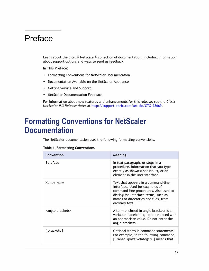
The NetScaler documentation uses the following formatting conventions.
Table 1. Formatting Conventions
Convention Meaning
Boldface In text paragraphs or steps in aprocedure, information that you typeexactly as shown (user input), or anelement in the user interface.
Monospace Text that appears in a command-lineinterface. Used for examples ofcommand-line procedures. Also used todistinguish interface terms, such asnames of directories and files, fromordinary text.
<angle brackets> A term enclosed in angle brackets is avariable placeholder, to be replaced withan appropriate value. Do not enter theangle brackets.
[ brackets ] Optional items in command statements.For example, in the following command,[ -range <positiveInteger> ] means that
17
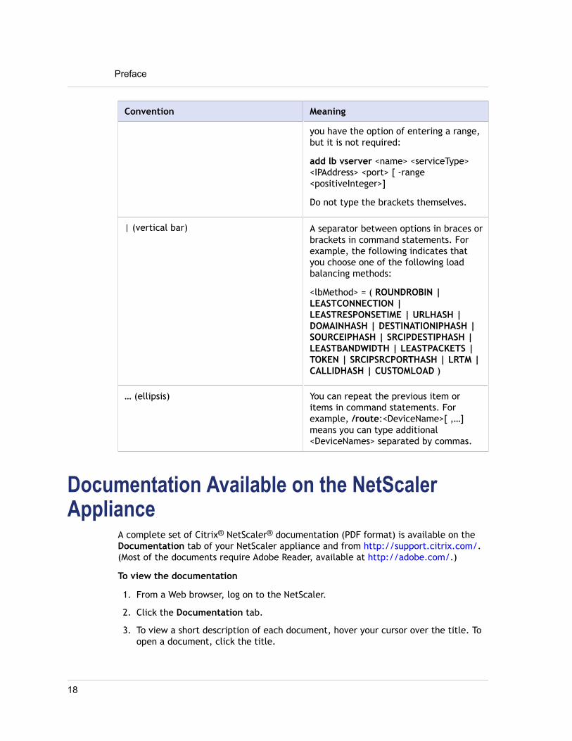
Convention Meaning
you have the option of entering a range,but it is not required:
add lb vserver <name> <serviceType><IPAddress> <port> [ -range<positiveInteger>]
Do not type the brackets themselves.
| (vertical bar) A separator between options in braces orbrackets in command statements. Forexample, the following indicates thatyou choose one of the following loadbalancing methods:
<lbMethod> = ( ROUNDROBIN |LEASTCONNECTION |LEASTRESPONSETIME | URLHASH |DOMAINHASH | DESTINATIONIPHASH |SOURCEIPHASH | SRCIPDESTIPHASH |LEASTBANDWIDTH | LEASTPACKETS |TOKEN | SRCIPSRCPORTHASH | LRTM |CALLIDHASH | CUSTOMLOAD )
… (ellipsis) You can repeat the previous item oritems in command statements. Forexample, /route:<DeviceName>[ ,…]means you can type additional<DeviceNames> separated by commas.
Documentation Available on the NetScalerAppliance
A complete set of Citrix® NetScaler® documentation (PDF format) is available on theDocumentation tab of your NetScaler appliance and from http://support.citrix.com/.(Most of the documents require Adobe Reader, available at http://adobe.com/.)
To view the documentation
1. From a Web browser, log on to the NetScaler.
2. Click the Documentation tab.
3. To view a short description of each document, hover your cursor over the title. Toopen a document, click the title.
Preface
18
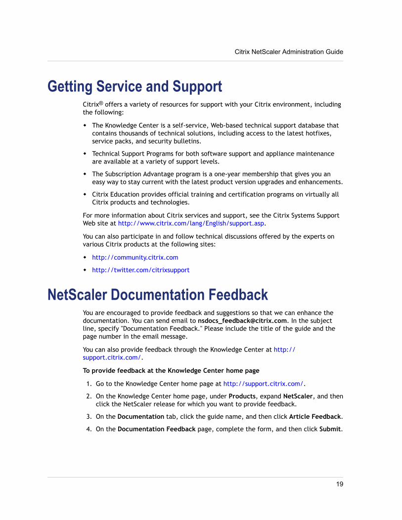
Getting Service and SupportCitrix® offers a variety of resources for support with your Citrix environment, includingthe following:
w The Knowledge Center is a self-service, Web-based technical support database thatcontains thousands of technical solutions, including access to the latest hotfixes,service packs, and security bulletins.
w Technical Support Programs for both software support and appliance maintenanceare available at a variety of support levels.
w The Subscription Advantage program is a one-year membership that gives you aneasy way to stay current with the latest product version upgrades and enhancements.
w Citrix Education provides official training and certification programs on virtually allCitrix products and technologies.
For more information about Citrix services and support, see the Citrix Systems SupportWeb site at http://www.citrix.com/lang/English/support.asp.
You can also participate in and follow technical discussions offered by the experts onvarious Citrix products at the following sites:
w http://community.citrix.com
w http://twitter.com/citrixsupport
NetScaler Documentation FeedbackYou are encouraged to provide feedback and suggestions so that we can enhance thedocumentation. You can send email to [email protected]. In the subjectline, specify "Documentation Feedback." Please include the title of the guide and thepage number in the email message.
You can also provide feedback through the Knowledge Center at http://support.citrix.com/.
To provide feedback at the Knowledge Center home page
1. Go to the Knowledge Center home page at http://support.citrix.com/.
2. On the Knowledge Center home page, under Products, expand NetScaler, and thenclick the NetScaler release for which you want to provide feedback.
3. On the Documentation tab, click the guide name, and then click Article Feedback.
4. On the Documentation Feedback page, complete the form, and then click Submit.
Citrix NetScaler Administration Guide
19

Preface
20
Chapter 1
Authentication and Authorization
Topics:• Configuring Users and
Groups
• Configuring CommandPolicies
• Resetting the DefaultAdministrator (nsroot)Password
• Example of a User Scenario
• Configuring External UserAuthentication
To configure Citrix® NetScaler® authentication andauthorization, you must first define the users who have accessto the NetScaler appliance, and then you can organize theseusers into groups. After configuring users and groups, youneed to configure command policies to define types of access,and assign the policies to users and/or groups.
You must log on as an administrator to configure users,groups, and command policies. The default NetScaleradministrator user name is nsroot. After logging on as thedefault administrator, you should change the password for thensroot account. Once you have changed the password, no usercan access the NetScaler appliance until you create anaccount for that user. If you forget the administrator passwordafter changing it from the default, you can reset it to nsroot.
21
Configuring Users and GroupsYou must define your users by configuring accounts for them. To simplify themanagement of user accounts, you can organize them into groups.
You can also customize the NetScaler command-line prompt for a user. Prompts can bedefined in a user’s configuration, in a user-group configuration, and in the globalconfiguration. The prompt displayed for a given user is determined by the followingorder of precedence:
1. Display the prompt as defined in the user's configuration.
2. Display the prompt as defined in the group configuration for the user’s group.
3. Display the prompt as defined in the system global configuration.
Configuring User AccountsTo configure user accounts, you simply specify user names and passwords. You canchange passwords and remove user accounts at any time.
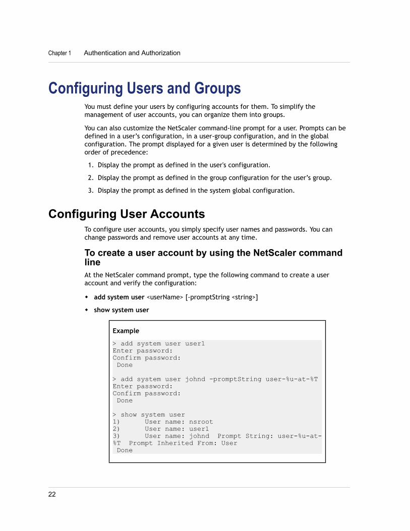
To create a user account by using the NetScaler commandlineAt the NetScaler command prompt, type the following command to create a useraccount and verify the configuration:
w add system user <userName> [-promptString <string>]
w show system user
Example
> add system user user1Enter password:Confirm password: Done
> add system user johnd -promptString user-%u-at-%TEnter password:Confirm password: Done
> show system user1) User name: nsroot2) User name: user13) User name: johnd Prompt String: user-%u-at-%T Prompt Inherited From: User Done
Chapter 1 Authentication and Authorization
22
To modify or remove a user account by using the NetScalercommand linew To modify a user's password, type the set system user <userName> command and
the parameters to be changed, with their new values.
w To remove a user account, type the rm system user <userName> command.
Parameters for configuring a user accountuserName
A name for the user. The name can begin with a letter, number, or the underscoresymbol, and can consist of from one to 31 letters, numbers, and the hyphen (-),period (.), pound (#), space ( ), at sign (@), equals (=), colon (:), and underscore (_)symbols.
passwordA password that the user uses to log on.
promptStringA name for the user’s NetScaler command-line prompt. The name can consist ofletters, numbers, the hyphen (-), period (.) pound (#), space ( ), at sign (@), equals(=), colon (:), underscore (_) symbols, and the following variables:
w %u—Will be replaced by the user name.
w %h—Will be replaced by the host name of the NetScaler appliance.
w %t—Will be replaced by the current time in 12-hour format.
w %T—Will be replaced by the current time in 24-hour format.
w %d—Will be replaced by the current date.
w %s—Will be replaced by the state of the NetScaler appliance.
A maximum of 63 characters are allowed for this parameter. A variable (for example,%u) is counted as two characters. The resulting prompt can be longer than 63characters.
To configure a user account by using the configuration utility1. In the navigation pane, expand System and click Users.
2. In the details pane, do one of the following:
• To create a user account, click Add.
• To modify an existing user account, select the user, and then click Open.
3. In the Create System User or Configure System User dialog box, specify values forthe parameters, which correspond to parameters described in "Parameters forconfiguring a user account" as shown:
• User Name*—userName (Cannot be changed for an existing user.)
Citrix NetScaler Administration Guide
23
• Password*—password
• Confirm Password*—password
• CLI Prompt—promptString (Optional)
* A required parameter
4. Click Create or OK, and then click Close.A message appears in the status bar, stating that the user has been configuredsuccessfully.
Configuring User GroupsAfter configuring a user group, you can easily grant the same access rights to everyonein the group. To configure a group, you create the group and bind users to the group.You can bind each user account to more than one group. Binding user accounts tomultiple groups may allow more flexibility when applying command policies.
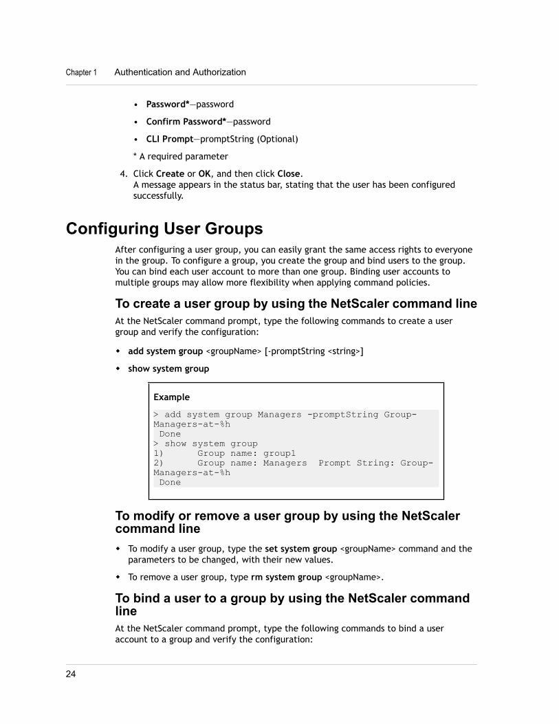
To create a user group by using the NetScaler command lineAt the NetScaler command prompt, type the following commands to create a usergroup and verify the configuration:
w add system group <groupName> [-promptString <string>]
w show system group
Example
> add system group Managers -promptString Group-Managers-at-%h Done> show system group1) Group name: group12) Group name: Managers Prompt String: Group-Managers-at-%h Done
To modify or remove a user group by using the NetScalercommand linew To modify a user group, type the set system group <groupName> command and the
parameters to be changed, with their new values.
w To remove a user group, type rm system group <groupName>.
To bind a user to a group by using the NetScaler commandlineAt the NetScaler command prompt, type the following commands to bind a useraccount to a group and verify the configuration:
Chapter 1 Authentication and Authorization
24
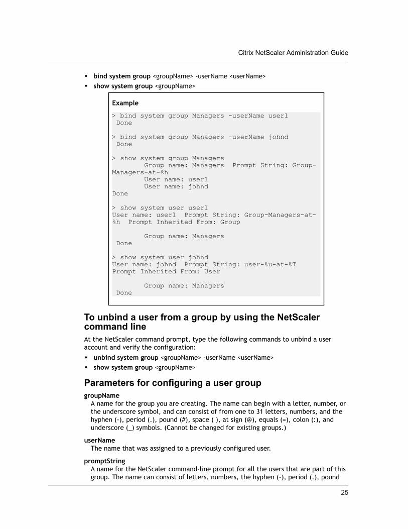
w bind system group <groupName> -userName <userName>w show system group <groupName>
Example
> bind system group Managers -userName user1 Done
> bind system group Managers -userName johnd Done
> show system group Managers Group name: Managers Prompt String: Group-Managers-at-%h User name: user1 User name: johndDone
> show system user user1User name: user1 Prompt String: Group-Managers-at-%h Prompt Inherited From: Group
Group name: Managers Done
> show system user johndUser name: johnd Prompt String: user-%u-at-%T Prompt Inherited From: User
Group name: Managers Done
To unbind a user from a group by using the NetScalercommand lineAt the NetScaler command prompt, type the following commands to unbind a useraccount and verify the configuration:
w unbind system group <groupName> -userName <userName>w show system group <groupName>
Parameters for configuring a user groupgroupName
A name for the group you are creating. The name can begin with a letter, number, orthe underscore symbol, and can consist of from one to 31 letters, numbers, and thehyphen (-), period (.), pound (#), space ( ), at sign (@), equals (=), colon (:), andunderscore (_) symbols. (Cannot be changed for existing groups.)
userNameThe name that was assigned to a previously configured user.
promptStringA name for the NetScaler command-line prompt for all the users that are part of thisgroup. The name can consist of letters, numbers, the hyphen (-), period (.), pound
Citrix NetScaler Administration Guide
25
(#), space ( ), at sign (@), equals (=), colon (:), underscore (_) symbols, and thefollowing variables:
w %u—Will be replaced by the user name.
w %h—Will be replaced by the host name of the NetScaler appliance.
w %t—Will be replaced by the current time in 12-hour format.
w %T—Will be replaced by the current time in 24-hour format.
w %d—Will be replaced by the current date.
w %s—Will be replaced by the state of the NetScaler appliance.
A maximum of 63 characters are allowed for this parameter. A variable (for example,%u) is counted as two characters. The resulting prompt can be longer than 63characters.
To configure a user group by using the configuration utility1. In the navigation pane, expand System, and then click Groups.
2. In the details pane, do one of the following:
• To create a new user group, click Add.
• To modify an existing user group, select the group, and then click Open.
3. In the Create System Group or Configure System Group dialog box, specify valuesfor the following parameters, which correspond to parameters described in"Parameters for configuring a user group" as shown:
• Group Name*—groupName (Required for a new group. Cannot be changed foran existing group.)
• CLI Prompt—promptString (Optional)
* A required parameter
4. Under Members, select users from the Available Users list and click Add to movethem to the Configured Users list.
5. Click Create or OK, and then click Close.A message appears in the status bar, stating that the group has been configuredsuccessfully.
Configuring Command PoliciesCommand policies regulate which commands, command groups, vservers, and otherentities that users and user groups are permitted to use.
The Citrix® NetScaler® appliance provides a set of built-in command policies, and youcan configure custom policies. To apply the policies, you bind them to users and/orgroups.
Chapter 1 Authentication and Authorization
26
Here are the key points to keep in mind when defining and applying command policies.
w You cannot create global command policies. Command policies must be bounddirectly to NetScaler users and groups.
w Users or groups with no associated command policies are subject to the default (DENY-ALL) command policy, and are therefore unable to execute any configurationcommands until the proper command policies are bound to their accounts.
w All users inherit the policies of the groups to which they belong.
w You must assign a priority to a command policy when you bind it to a user accountor group account. This enables the NetScaler to determine which policy has prioritywhen two or more conflicting policies apply to the same user or group.
w The following commands are available by default to any user and are unaffected byany command you specify:
help cli, show cli attribute, clear cli prompt, alias, unalias, help, history, quit,exit, whoami, config, set cli mode, unset cli mode, show cli mode, set cliprompt, and show cli prompt.
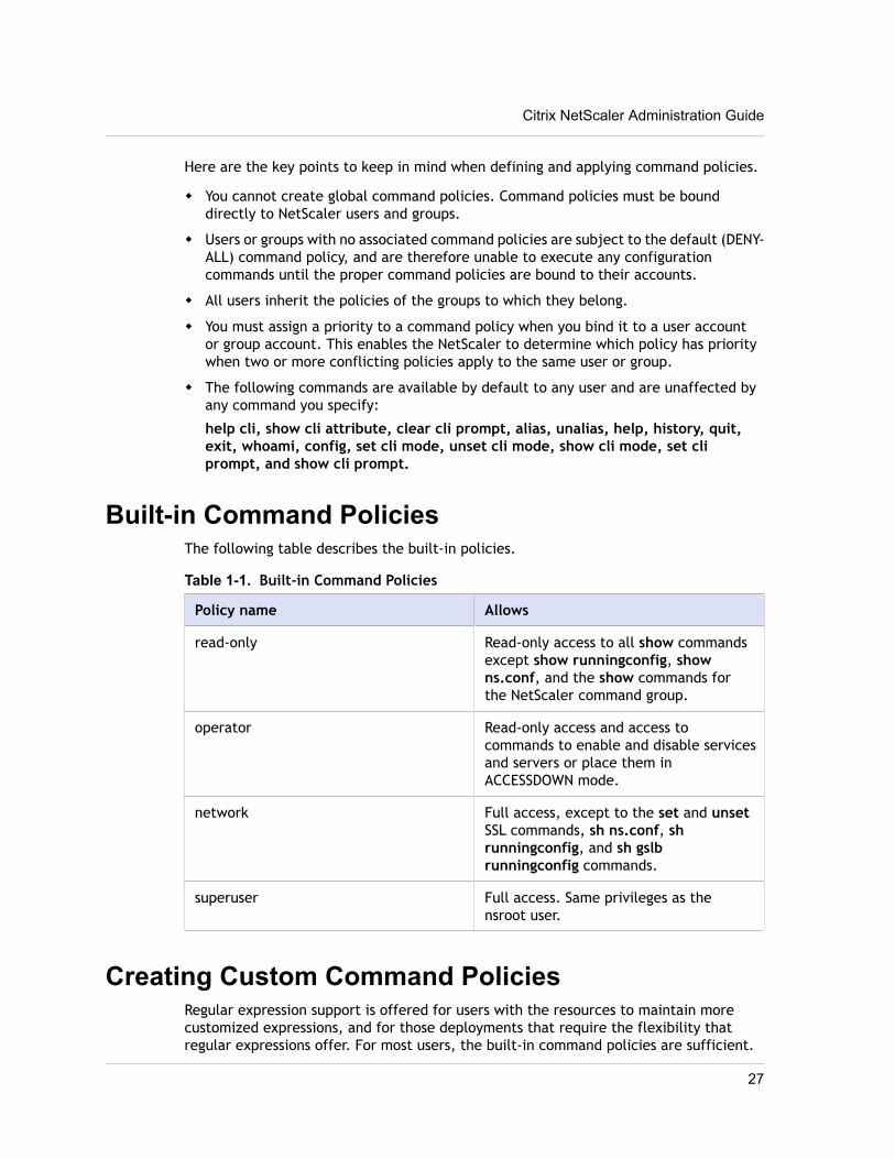
Built-in Command PoliciesThe following table describes the built-in policies.
Table 1-1. Built-in Command Policies
Policy name Allows
read-only Read-only access to all show commandsexcept show runningconfig, showns.conf, and the show commands forthe NetScaler command group.
operator Read-only access and access tocommands to enable and disable servicesand servers or place them inACCESSDOWN mode.
network Full access, except to the set and unsetSSL commands, sh ns.conf, shrunningconfig, and sh gslbrunningconfig commands.
superuser Full access. Same privileges as thensroot user.
Creating Custom Command PoliciesRegular expression support is offered for users with the resources to maintain morecustomized expressions, and for those deployments that require the flexibility thatregular expressions offer. For most users, the built-in command policies are sufficient.
Citrix NetScaler Administration Guide
27

Users who need additional levels of control but are unfamiliar with regular expressionsmay want to use only simple expressions, such as those in the examples provided in thissection, to maintain policy readability.
When you use a regular expression to create a command policy, keep the following inmind.
w When you use regular expressions to define commands that will be affected by acommand policy, you must enclose the commands in double quotation marks. Forexample, to create a command policy that includes all commands that begin withshow, type the following:
"^show .*$"
To create a command policy that includes all commands that begin with rm, typethe following:
"^rm .*$"
w Regular expressions used in command policies are not case sensitive.
The following table lists examples of regular expressions:
Table 1-2. Examples of Regular Expressions for Command Policies
Command specification Matches these commands
"^rm\s+.*$" All remove actions, because all removeactions begin with the rm string,followed by a space and additionalparameters and flags.
"^show\s+.*$" All show commands, because all showactions begin with the show string,followed by a space and additionalparameters and flags.
"^shell$" The shell command alone, but notcombined with any other parameters orflags.
"^add\s+vserver\s+.*$" All create vserver actions, which consistof the add vserver command followedby a space and additional parametersand flags.
"^add\s+(lb\s+vserver)\s+.*" All create lb vserver actions, whichconsist of the add lb vserver commandfollowed by a space and additionalparameters and flags.
The following table shows the command specifications for each of the built-incommand policies.
Chapter 1 Authentication and Authorization
28
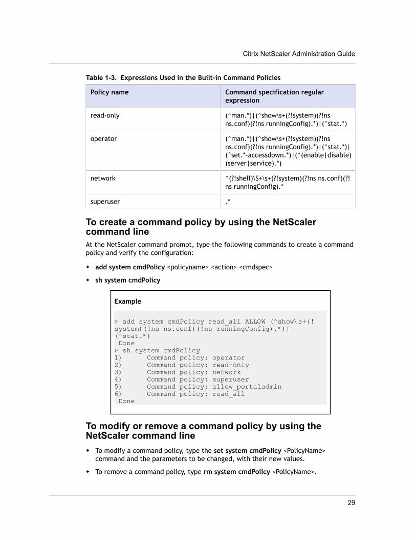
Table 1-3. Expressions Used in the Built-in Command Policies
Policy name Command specification regularexpression
read-only (^man.*)|(^show\s+(?!system)(?!nsns.conf)(?!ns runningConfig).*)|(^stat.*)
operator (^man.*)|(^show\s+(?!system)(?!nsns.conf)(?!ns runningConfig).*)|(^stat.*)|(^set.*-accessdown.*)|(^(enable|disable)(server|service).*)
network ^(?!shell)\S+\s+(?!system)(?!ns ns.conf)(?!ns runningConfig).*
superuser .*
To create a command policy by using the NetScalercommand lineAt the NetScaler command prompt, type the following commands to create a commandpolicy and verify the configuration:
w add system cmdPolicy <policyname> <action> <cmdspec>
w sh system cmdPolicy
Example
> add system cmdPolicy read_all ALLOW (^show\s+(!system)(!ns ns.conf)(!ns runningConfig).*)|(^stat.*) Done> sh system cmdPolicy1) Command policy: operator2) Command policy: read-only3) Command policy: network4) Command policy: superuser5) Command policy: allow_portaladmin6) Command policy: read_all Done
To modify or remove a command policy by using theNetScaler command linew To modify a command policy, type the set system cmdPolicy <PolicyName>
command and the parameters to be changed, with their new values.
w To remove a command policy, type rm system cmdPolicy <PolicyName>.
Citrix NetScaler Administration Guide
29
Note: The built-in command policies cannot be removed.
Parameters for configuring a command policypolicyname
A name for the command policy you are creating. The name can begin with a letter,number, or the underscore symbol, and can consist of from one to 31 letters,numbers, and the hyphen (-), period (.), pound (#), space ( ), at sign (@), equals (=),colon (:), and underscore (_) symbols. (Cannot be changed for existing policies.)
actionThe action the policy applies when the command specification pattern matches.Possible values: ALLOW, DENY
cmdspecRule (expression) that the policy uses for pattern matching.
To configure a command policy by using the configurationutility1. In the navigation pane, expand System, and then click Command Policies.
2. In the details pane, do one of the following:
• To create a command policy, click Add.
• To modify an existing command policy, select the command policy, and thenclick Open.
3. In the Create Command Policy or Configure Command Policy dialog box, specifyvalues for the parameters, which correspond to the parameters described in"Parameters for configuring a command policy" as shown:
• Policy Name*—policyname (Cannot be changed for an existing policy.)
• Action—action
• Command Spec*—cmdspec (You can type a complete expression directly into thetext area, or you can click Add or Regex Tokens for assistance.The Add iconopens the Add Command dialog box, in which you can select a NetScaler entityand then select an operation to perform on the entity. The Regex Tokens icondisplays regular expression tokens, which you can add to your expression byselecting them.)
* A required parameter
4. Click Create or OK, and then click Close.A message appears in the status bar, stating that the command policy has beenconfigured successfully.
Binding Command Policies to Users and GroupsOnce you have defined your command policies, you must bind them to the appropriateuser accounts and groups.
Chapter 1 Authentication and Authorization
30
When you bind a policy, you must assign it a priority so that the NetScaler appliancecan determine which command policy to follow when two or more applicable commandpolicies are in conflict.
Command policies are evaluated in the following order:
w Command policies bound directly to users and the corresponding groups areevaluated according to priority number. A command policy with a lower prioritynumber is evaluated before one with a higher priority number. Therefore, anyprivileges the lower-numbered command policy explicitly grants or denies are notoverridden by a higher-numbered command policy.
w When two command policies, one bound to a user account and other to a group,have the same priority number, the command policy bound directly to the useraccount is evaluated first.
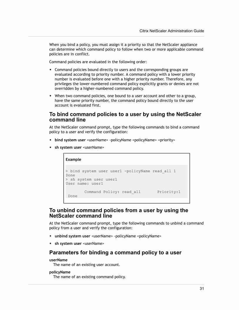
To bind command policies to a user by using the NetScalercommand lineAt the NetScaler command prompt, type the following commands to bind a commandpolicy to a user and verify the configuration:
w bind system user <userName> -policyName <policyName> <priority>
w sh system user <userName>
Example
> bind system user user1 -policyName read_all 1Done> sh system user user1User name: user1
Command Policy: read_all Priority:1 Done
To unbind command policies from a user by using theNetScaler command lineAt the NetScaler command prompt, type the following commands to unbind a commandpolicy from a user and verify the configuration:
w unbind system user <userName> -policyName <policyName>
w sh system user <userName>
Parameters for binding a command policy to a useruserName
The name of an existing user account.
policyNameThe name of an existing command policy.
Citrix NetScaler Administration Guide
31
priorityThe priority assigned to this policy.
To bind command policies to a user by using theconfiguration utility1. In the navigation pane, expand System, and then click Users.
2. In the details pane, select the user to which you want to bind a command policy,and then click Open.
3. In the Configure System User dialog box, under Command Policies, all of thecommand policies configured on your NetScaler appear on the list. Select thecheck box next to the name of the policy you want to bind to this user.
4. In the Priority column to the left, modify the default priority as needed to ensurethat the policy is evaluated in the proper order.
5. Click OK.A message appears in the status bar, stating that the user has been configuredsuccessfully.
To bind command policies to a group by using theNetScaler command lineAt the NetScaler command prompt, type the following commands to bind a commandpolicy to a user group and verify the configuration:
w bind system group <groupName> -policyName <policyName> <priority>
w sh system group <groupName>
Example
> bind system group Managers -policyName read_all 1Done> sh system group Managers Group name: Managers
User name: johnd
Command policy: read_all Priority:1 Done
To unbind command policies from a group by using theNetScaler command lineAt the NetScaler command prompt, type the following commands to unbind a commandpolicy from a user group and verify the configuration:
w unbind system group <groupName> -policyName <policyName>
Chapter 1 Authentication and Authorization
32
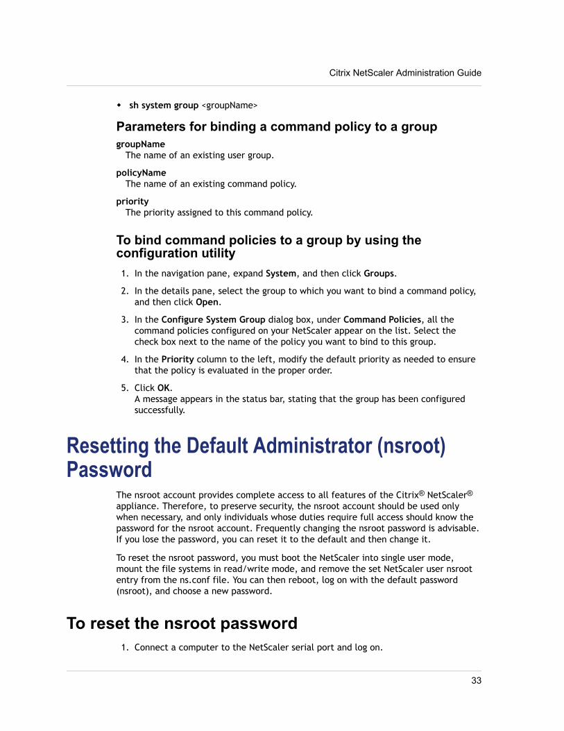
w sh system group <groupName>
Parameters for binding a command policy to a groupgroupName
The name of an existing user group.
policyNameThe name of an existing command policy.
priorityThe priority assigned to this command policy.
To bind command policies to a group by using theconfiguration utility1. In the navigation pane, expand System, and then click Groups.
2. In the details pane, select the group to which you want to bind a command policy,and then click Open.
3. In the Configure System Group dialog box, under Command Policies, all thecommand policies configured on your NetScaler appear on the list. Select thecheck box next to the name of the policy you want to bind to this group.
4. In the Priority column to the left, modify the default priority as needed to ensurethat the policy is evaluated in the proper order.
5. Click OK.A message appears in the status bar, stating that the group has been configuredsuccessfully.
Resetting the Default Administrator (nsroot)Password
The nsroot account provides complete access to all features of the Citrix® NetScaler®
appliance. Therefore, to preserve security, the nsroot account should be used onlywhen necessary, and only individuals whose duties require full access should know thepassword for the nsroot account. Frequently changing the nsroot password is advisable.If you lose the password, you can reset it to the default and then change it.
To reset the nsroot password, you must boot the NetScaler into single user mode,mount the file systems in read/write mode, and remove the set NetScaler user nsrootentry from the ns.conf file. You can then reboot, log on with the default password(nsroot), and choose a new password.
To reset the nsroot password1. Connect a computer to the NetScaler serial port and log on.
Citrix NetScaler Administration Guide
33
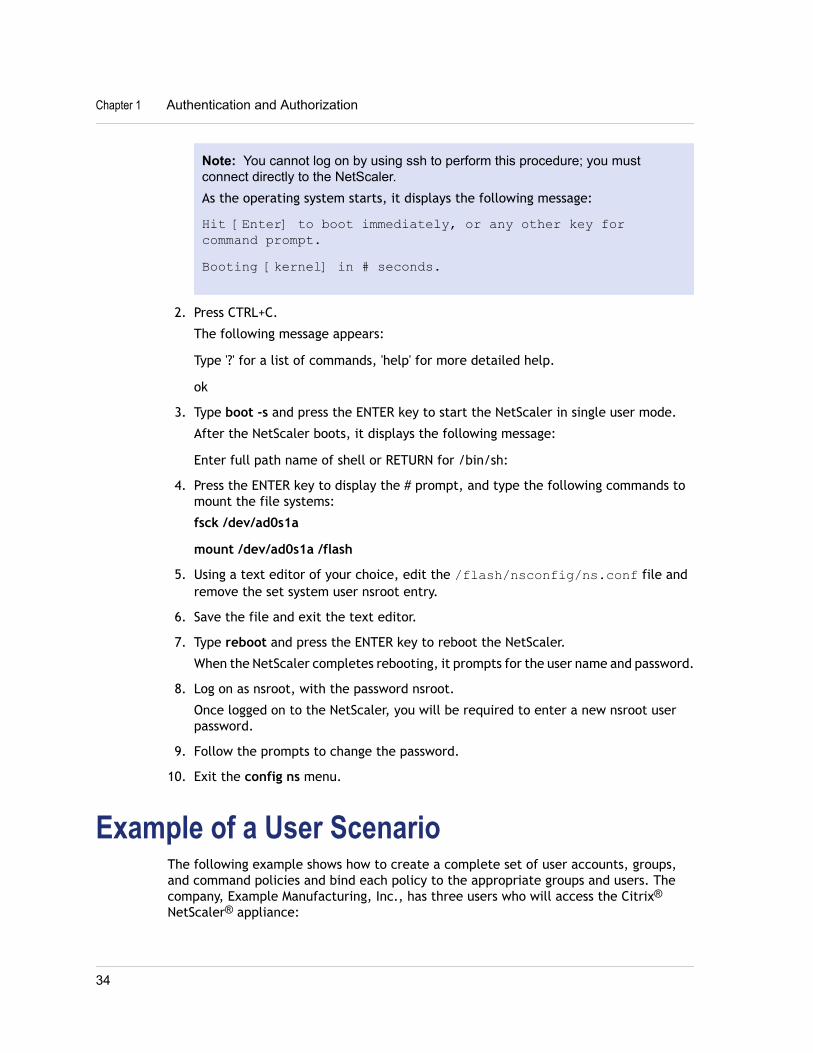
Note: You cannot log on by using ssh to perform this procedure; you mustconnect directly to the NetScaler.As the operating system starts, it displays the following message:
Hit [Enter] to boot immediately, or any other key forcommand prompt.Booting [kernel] in # seconds.
2. Press CTRL+C.
The following message appears:
Type '?' for a list of commands, 'help' for more detailed help.
ok
3. Type boot -s and press the ENTER key to start the NetScaler in single user mode.
After the NetScaler boots, it displays the following message:
Enter full path name of shell or RETURN for /bin/sh:
4. Press the ENTER key to display the # prompt, and type the following commands tomount the file systems:
fsck /dev/ad0s1a
mount /dev/ad0s1a /flash
5. Using a text editor of your choice, edit the /flash/nsconfig/ns.conf file andremove the set system user nsroot entry.
6. Save the file and exit the text editor.
7. Type reboot and press the ENTER key to reboot the NetScaler.
When the NetScaler completes rebooting, it prompts for the user name and password.
8. Log on as nsroot, with the password nsroot.
Once logged on to the NetScaler, you will be required to enter a new nsroot userpassword.
9. Follow the prompts to change the password.
10. Exit the config ns menu.
Example of a User ScenarioThe following example shows how to create a complete set of user accounts, groups,and command policies and bind each policy to the appropriate groups and users. Thecompany, Example Manufacturing, Inc., has three users who will access the Citrix®
NetScaler® appliance:
Chapter 1 Authentication and Authorization
34
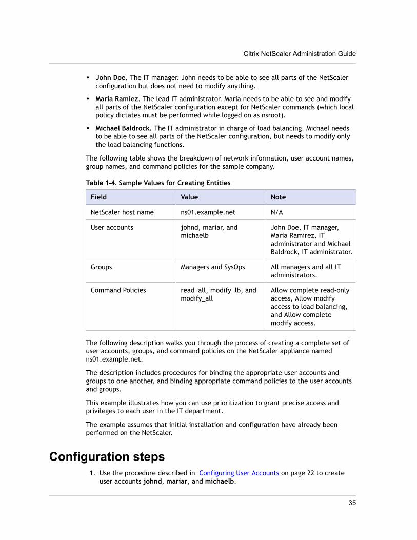
w John Doe. The IT manager. John needs to be able to see all parts of the NetScalerconfiguration but does not need to modify anything.
w Maria Ramiez. The lead IT administrator. Maria needs to be able to see and modifyall parts of the NetScaler configuration except for NetScaler commands (which localpolicy dictates must be performed while logged on as nsroot).
w Michael Baldrock. The IT administrator in charge of load balancing. Michael needsto be able to see all parts of the NetScaler configuration, but needs to modify onlythe load balancing functions.
The following table shows the breakdown of network information, user account names,group names, and command policies for the sample company.
Table 1-4. Sample Values for Creating Entities
Field Value Note
NetScaler host name ns01.example.net N/A
User accounts johnd, mariar, andmichaelb
John Doe, IT manager,Maria Ramirez, ITadministrator and MichaelBaldrock, IT administrator.
Groups Managers and SysOps All managers and all ITadministrators.
Command Policies read_all, modify_lb, andmodify_all
Allow complete read-onlyaccess, Allow modifyaccess to load balancing,and Allow completemodify access.
The following description walks you through the process of creating a complete set ofuser accounts, groups, and command policies on the NetScaler appliance namedns01.example.net.
The description includes procedures for binding the appropriate user accounts andgroups to one another, and binding appropriate command policies to the user accountsand groups.
This example illustrates how you can use prioritization to grant precise access andprivileges to each user in the IT department.
The example assumes that initial installation and configuration have already beenperformed on the NetScaler.
Configuration steps1. Use the procedure described in Configuring User Accounts on page 22 to create
user accounts johnd, mariar, and michaelb.
Citrix NetScaler Administration Guide
35
2. Use the procedure described in Configuring User Groups on page 24 to create usergroups Managers and SysOps, and then bind the users mariar and michaelb to theSysOps group and the user johnd to the Managers group.
3. Use the procedure described in Creating Custom Command Policies on page 27 tocreate the following command policies:
• read_all with action Allow and command spec "(^show\s+(?!system)(?!ns ns.conf)(?!ns runningConfig).*)|(^stat.*)"
• modify_lb with action as Allow and the command spec "^set\s+lb\s+.*$"
• modify_all with action as Allow and the command spec "^\S+\s+(?!system).*"
4. Use the procedure described in Binding Command Policies to Users and Groups onpage 30 to bind the read_all command policy to the SysOps group, with priorityvalue 1.
5. Use the procedure described in Binding Command Policies to Users and Groups onpage 30 to bind the modify_lb command policy to user michaelb, with priorityvalue 5.
The configuration you just created results in the following:
w John Doe, the IT manager, has read-only access to the entire NetScalerconfiguration, but he cannot make modifications.
w Maria Ramirez, the IT lead, has near-complete access to all areas of the NetScalerconfiguration, having to log on only to perform NetScaler-level commands.
w Michael Baldrock, the IT administrator responsible for load balancing, has read-onlyaccess to the NetScaler configuration, and can modify the configuration options forload balancing.
The set of command policies that applies to a specific user is a combination ofcommand policies applied directly to the user's account and command policies appliedto the group(s) of which the user is a member.
Each time a user enters a command, the operating system searches the commandpolicies for that user until it finds a policy with an ALLOW or DENY action that matchesthe command. When it finds a match, the operating system stops its command policysearch and allows or denies access to the command.
If the operating system finds no matching command policy, it denies the user access tothe command, in accordance with the NetScaler appliance's default deny policy.
Note: When placing a user into multiple groups, take care not to cause unintendeduser command restrictions or privileges. To avoid these conflicts, when organizing yourusers in groups, bear in mind the NetScaler command policy search procedure andpolicy ordering rules.
Configuring External User AuthenticationExternal user authentication is the process of authenticating the users of the Citrix®
NetScaler® appliance by using an external authentication server. The NetScaler
Chapter 1 Authentication and Authorization
36
supports LDAP, RADIUS, TACACS+, and NT4 authentication servers. To configure externaluser authentication, you must create authentication policies. You can configure one ormany authentication policies, depending on your authentication needs. Anauthentication policy consists of an expression and an action. Authentication policiesuse NetScaler classic expressions, which are described in detail in the Citrix NetScalerPolicy Configuration and Reference Guide at http://support.citrix.com/article/ctx128673.
After creating an authentication policy, you bind it to the system global entity andassign a priority to it. You can create simple server configurations by binding a singleauthentication policy to the system global entity. Or, you can configure a cascade ofauthentication servers by binding multiple policies to the system global entity. If noauthentication policies are bound to the system, users are authenticated by theonboard system.
Note: User accounts must be configured on the NetScaler appliance before users canbe externally authenticated. You must first create an onboard system user for all userswho will access the appliance, so that you can bind command policies to the useraccounts. Regardless of the authentication source, users cannot log on if they are notgranted sufficient command authorization through command policies bound to theiruser accounts or to a group of which they are a member.
Configuring LDAP AuthenticationYou can configure the NetScaler to authenticate user access with one or more LDAPservers. LDAP authorization requires identical group names in Active Directory, on theLDAP server, and on the NetScaler. The characters and case must also be the same.
By default, LDAP authentication is secured by using SSL/TLS protocol. There are twotypes of secure LDAP connections. In the first type, the LDAP server accepts the SSL/TLS connection on a port separate from the port used to accept clear LDAPconnections. After users establish the SSL/TLS connection, LDAP traffic can be sentover the connection. The second type allows both unsecure and secure LDAPconnections and is handled by a single port on the server. In this scenario, to create asecure connection, the client first establishes a clear LDAP connection. Then the LDAPcommand StartTLS is sent to the server over the connection. If the LDAP serversupports StartTLS, the connection is converted to a secure LDAP connection by using TLS.
The port numbers for LDAP connections are:
w 389 for unsecured LDAP connections
w 636 for secure LDAP connections
w 3268 for Microsoft unsecure LDAP connections
w 3269 for Microsoft secure LDAP connections
LDAP connections that use the StartTLS command use port number 389. If port numbers389 or 3268 are configured on the NetScaler, it tries to use StartTLS to make theconnection. If any other port number is used, connection attempts use SSL/TLS. IfStartTLS or SSL/TLS cannot be used, the connection fails.
Citrix NetScaler Administration Guide
37
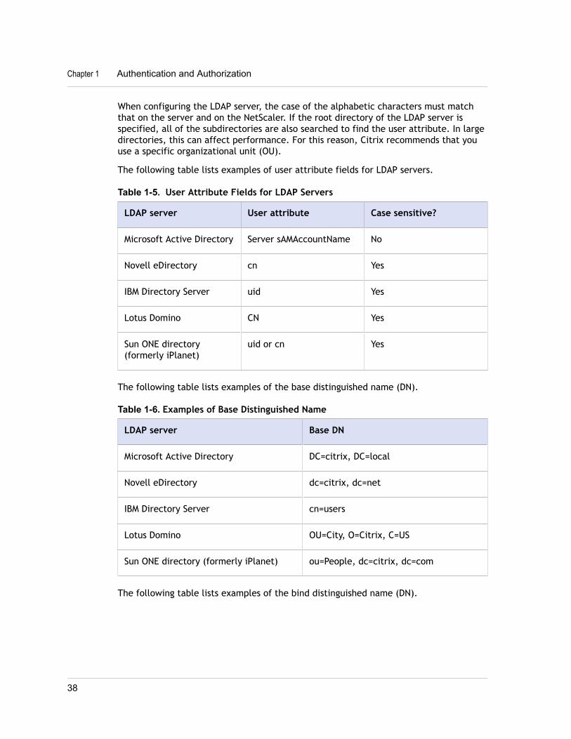
When configuring the LDAP server, the case of the alphabetic characters must matchthat on the server and on the NetScaler. If the root directory of the LDAP server isspecified, all of the subdirectories are also searched to find the user attribute. In largedirectories, this can affect performance. For this reason, Citrix recommends that youuse a specific organizational unit (OU).
The following table lists examples of user attribute fields for LDAP servers.
Table 1-5. User Attribute Fields for LDAP Servers
LDAP server User attribute Case sensitive?
Microsoft Active Directory Server sAMAccountName No
Novell eDirectory cn Yes
IBM Directory Server uid Yes
Lotus Domino CN Yes
Sun ONE directory(formerly iPlanet)
uid or cn Yes
The following table lists examples of the base distinguished name (DN).
Table 1-6. Examples of Base Distinguished Name
LDAP server Base DN
Microsoft Active Directory DC=citrix, DC=local
Novell eDirectory dc=citrix, dc=net
IBM Directory Server cn=users
Lotus Domino OU=City, O=Citrix, C=US
Sun ONE directory (formerly iPlanet) ou=People, dc=citrix, dc=com
The following table lists examples of the bind distinguished name (DN).
Chapter 1 Authentication and Authorization
38
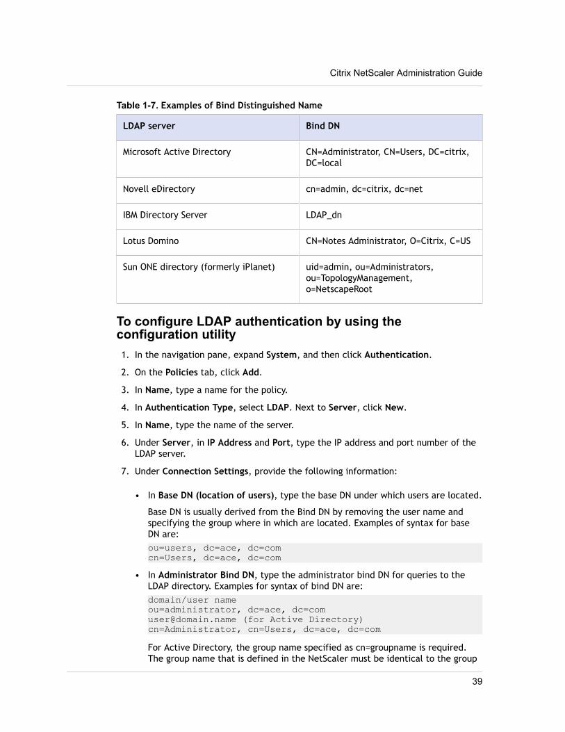
Table 1-7. Examples of Bind Distinguished Name
LDAP server Bind DN
Microsoft Active Directory CN=Administrator, CN=Users, DC=citrix,DC=local
Novell eDirectory cn=admin, dc=citrix, dc=net
IBM Directory Server LDAP_dn
Lotus Domino CN=Notes Administrator, O=Citrix, C=US
Sun ONE directory (formerly iPlanet) uid=admin, ou=Administrators,ou=TopologyManagement,o=NetscapeRoot
To configure LDAP authentication by using theconfiguration utility1. In the navigation pane, expand System, and then click Authentication.
2. On the Policies tab, click Add.
3. In Name, type a name for the policy.
4. In Authentication Type, select LDAP. Next to Server, click New.
5. In Name, type the name of the server.
6. Under Server, in IP Address and Port, type the IP address and port number of theLDAP server.
7. Under Connection Settings, provide the following information:
• In Base DN (location of users), type the base DN under which users are located.
Base DN is usually derived from the Bind DN by removing the user name andspecifying the group where in which are located. Examples of syntax for baseDN are:ou=users, dc=ace, dc=comcn=Users, dc=ace, dc=com
• In Administrator Bind DN, type the administrator bind DN for queries to theLDAP directory. Examples for syntax of bind DN are:domain/user nameou=administrator, dc=ace, [email protected] (for Active Directory)cn=Administrator, cn=Users, dc=ace, dc=comFor Active Directory, the group name specified as cn=groupname is required.The group name that is defined in the NetScaler must be identical to the group
Citrix NetScaler Administration Guide
39
name that is defined on the LDAP server. For other LDAP directories, the groupname either is not required or, if required, is specified as ou=groupname.
The NetScaler binds to the LDAP server, using the administrator credentials, andthen searches for the user. After locating the user, the NetScaler unbinds theadministrator credentials and rebinds with the user credentials.
• In Administrator Password and Confirm Administrator Password, type theadministrator password for the LDAP server.
8. To retrieve additional LDAP settings automatically, click Retrieve Attributes. Thefields under Other Settings then populate automatically. If you do not want to dothis, skip to Step 12.
9. Under Other Settings, in Server Logon Name Attribute, type the attribute underwhich the NetScaler should look for user logon names for the LDAP server that youare configuring. The default is samAccountName.
10. In Group Attribute, leave the default memberOf for Active Directory or change itto that of the LDAP server type you are using. This attribute enables the NetScalerto obtain the groups associated with a user during authorization.
11. In Security Type, select the security type.If you select PLAINTEXT or TLS for security, use port number 389. If you selectSSL, use port number 636.
12. To allow users to change their LDAP password, select Allow Password Change.If you select PLAINTEXT as the security type, allowing users to change theirpasswords is not supported.
13. Click Create.
14. In the Create Authentication Policy dialog box, next to Named Expressions,select the expression, click Add Expression, click Create, and click Close.
After the LDAP server settings are configured on the NetScaler, bind the policy to thesystem global entity. For more information about binding authentication policiesglobally, see Binding the Authentication Policies to the System Global Entity on page44.
Determining attributes in the LDAP directoryIf you need help determining your LDAP directory attributes, you can easily look themup with the free LDAP browser from Softerra.
You can download the LDAP browser from the Softerra LDAP Administrator Web site at http://www.ldapbrowser.com. After the browser is installed, set the following attributes:
w The host name or IP address of your LDAP server.
w The port of your LDAP server. The default is 389.
w The base DN field can be left blank.
w The information provided by the LDAP browser can help you determine the base DNneeded for the Authentication tab.
Chapter 1 Authentication and Authorization
40
w The Anonymous Bind check determines whether the LDAP server requires usercredentials for the the browser to connect to it. If the LDAP server requirescredentials, leave the check box cleared.
After completing the settings, the LDAP browser displays the profile name in the leftpane and connects to the LDAP server.
Configuring RADIUS AuthenticationYou can configure the NetScaler appliance to authenticate user access with one ormore RADIUS servers. If you are using RSA SecurID, SafeWord, or Gemalto Protivaproducts, use a RADIUS server.
Your configuration might require using a network access server IP address (NAS IP) or anetwork access server identifier (NAS ID). When configuring your NetScaler to use aRADIUS authentication server, use the following guidelines:
w If you enable use of the NAS IP, the appliance sends its configured IP address to theRADIUS server, rather than the source IP address used in establishing the RADIUSconnection.
w If you configure the NAS ID, the appliance sends the identifier to the RADIUS server.If you do not configure the NAS ID, the appliance sends its host name to the RADIUSserver.
w When the NAS IP is enabled, the appliance ignores any NAS ID that was configuredby using the NAS IP to communicate with the RADIUS server.
To configure RADIUS authentication by using theconfiguration utility1. In the navigation pane, expand System, and then click Authentication.
2. On the Policies tab, click Add.
3. In Name, type a name for the policy.
4. In Authentication Type, select RADIUS.
5. Next to Server, click New.
6. In Name, type a name for the server.
7. Under Server, in IP Address, type the IP address of the RADIUS server.
8. In Port, type the port. The default is 1812.
9. Under Details, in Secret Key and Confirm Secret Key, type the RADIUS server secret.
10. In NAS ID, type the identifier number, and then click Create.
11. In the Create Authentication Policy dialog box, next to Named Expressions,select the expression, click Add Expression, click Create, and click Close.
After the RADIUS server settings are configured on the NetScaler, bind the policy to thesystem global entity. For more information about binding authentication policies
Citrix NetScaler Administration Guide
41
globally, see Binding the Authentication Policies to the System Global Entity on page44.
Choosing RADIUS authentication protocolsThe NetScaler appliance supports implementations of RADIUS that are configured to useany of several protocols for user authentication, including:
w Password Authentication Protocol
w Challenge-Handshake Authentication Protocol (CHAP)
w Microsoft Challenge-Handshake Authentication Protocol (MS-CHAP Version 1 andVersion 2)
If your deployment of the NetScaler is configured to use RADIUS authentication andyour RADIUS server is configured to use Password Authentication Protocol, you canstrengthen user authentication by assigning a strong shared secret to the RADIUS server.Strong RADIUS shared secrets consist of random sequences of uppercase and lowercaseletters, numbers, and punctuation, and are at least 22 characters long. If possible, usea random character generation program to determine RADIUS shared secrets.
To further protect RADIUS traffic, assign a different shared secret to each NetScalerappliance or virtual server. When you define clients on the RADIUS server, you can alsoassign a separate shared secret to each client. If you do this, you must configureseparately each NetScaler policy that uses RADIUS authentication.
Shared secrets are configured on the NetScaler when a RADIUS policy is created.
Configuring IP address extractionYou can configure the NetScaler to extract the IP address from a RADIUS server. When auser authenticates with the RADIUS server, the server returns a framed IP address thatis assigned to the user. The following are attributes for IP address extraction:
w Allows a remote RADIUS server to supply an IP address from the internal network fora user logged on to the NetScaler.
w Allows configuration for any RADIUS attribute using the type ipaddress, includingthose that are vendor encoded.
When configuring the RADIUS server for IP address extraction, you configure the vendoridentifier and the attribute type.
The vendor identifier enables the RADIUS server to assign an IP address to the clientfrom a pool of IP addresses that are configured on the RADIUS server. The vendor ID andattributes are used to make the association between the RADIUS client and the RADIUSserver. The vendor ID is the attribute in the RADIUS response that provides the IPaddress of the internal network. A value of zero indicates that the attribute is notvendor encoded. The attribute type is the remote IP address attribute in a RADIUSresponse. The minimum value is one and the maximum value is 255.
A common configuration is to extract the RADIUS attribute framed IP address. Thevendor ID is set to zero or is not specified. The attribute type is set to eight.
Chapter 1 Authentication and Authorization
42
To configure IP address extraction by using the configuration utility
1. In the navigation pane, expand System, and then click Authentication.
2. On the Policies tab, click Open.
3. In the Configure Authentication Policy dialog box, next to Server, click Modify.
4. Under Details, in Group Vendor Identifier, type the value.
5. In Group Attribute Type, type the value, and click OK twice.
Configuring TACACS+ AuthenticationYou can configure a TACACS+ server for authentication. Similar to RADIUSauthentication, TACACS+ uses a secret key, an IP address, and the port number. Thedefault port number is 49. To configure the NetScaler to use a TACACS+ server, providethe server IP address and the TACACS+ secret. The port needs to be specified only whenthe server port number in use is something other than the default port number of 49.
To configure TACACS+ authentication by using theconfiguration utility1. In the navigation pane, expand System, and then click Authentication.
2. On the Policies tab, click Add.
3. In Name, type a name for the policy.
4. In Authentication Type, select TACACS.
5. Next to Server, click New.
6. In Name, type a name for the server.
7. Under Server, type the IP address and port number of the TACACS+ server.
8. Under TACACS server information, in TACACS Key and Confirm TACACS key, typethe key.
9. In Authorization, select ON and click Create.
10. In the Create Authentication Policy dialog box, next to Named Expressions,select the expression, click Add Expression, click Create, and click Close.
After the TACACS+ server settings are configured on the NetScaler, bind the policy tothe system global entity. For more information about binding authentication policiesglobally, see Binding the Authentication Policies to the System Global Entity on page44.
Configuring NT4 AuthenticationYou can configure the NetScaler appliance to use Windows NT LAN Manager (NTLM)authentication to authenticate users against the user database on a Windows NT 4.0domain controller. A Windows NT 4.0 domain controller maintains domain user accounts
Citrix NetScaler Administration Guide
43
in a database on the Windows NT 4.0 server. A domain user account includes a username and password and other information about the user.
When a user logs on to the NetScaler, the user enters the user name and passwordmaintained in the domain user account on the Windows NT 4.0 server. The NetScalerconnects to the Windows NT 4.0 server and passes these credentials to the server. Theserver authenticates the user. If you need to configure the NetScaler to authenticateclients against a Windows NT 4.0 primary or backup domain controller, you need tospecify the server IP address, the domain name, and the domain administrator username and password of the person who is authorized to administer the domain. Theseparameters are necessary because the NetScaler joins the domain to communicateauthentication data.
NT4 authentication supports NTLMv1 and NTLMv2 authentication protocols only.
To configure NT4 authentication by using the configurationutility1. In the navigation pane, expand System, and then click Authentication.
2. On the Policies tab, click Add.
3. In Name, type a name for the policy.
4. In Authentication Type, select NT4.
5. Next to Server, click New.
6. In Server, type the name of the server.
7. Complete the settings as they are configured on your Windows NT 4.0 server andclick Create.
8. In the Create Authentication Policy dialog box, next to Named Expressions,select the expression, click Add Expression, click Create, and click Close.
When the settings for Windows NT 4.0 authentication are configured, bind the policy tothe system global entity. For more information about binding authentication policiesglobally, see Binding the Authentication Policies to the System Global Entity on page44.
Binding the Authentication Policies to the SystemGlobal Entity
When the authentication policies are configured, bind the policies to the system globalentity.
To bind an authentication policy globally by using theconfiguration utility1. In the navigation pane, expand System, and then click Authentication.
2. On the Policies tab, click Global Bindings.
Chapter 1 Authentication and Authorization
44
3. Under Details, click Insert Policy.
4. Under Policy Name, select the policy and click OK.
To unbind a global authentication policy by using theconfiguration utility1. In the navigation pane, expand System, and then click Authentication.
2. On the Policies tab, click Global Bindings.
3. In the Bind/Unbind Authentication Policies dialog box, in Policy Name, select thepolicy, click Unbind Policy and then click OK.
Citrix NetScaler Administration Guide
45

Chapter 1 Authentication and Authorization
46
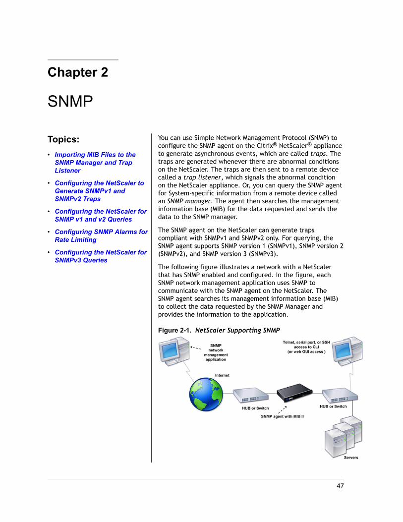
Chapter 2
SNMP
Topics:• Importing MIB Files to the
SNMP Manager and TrapListener
• Configuring the NetScaler toGenerate SNMPv1 andSNMPv2 Traps
• Configuring the NetScaler forSNMP v1 and v2 Queries
• Configuring SNMP Alarms forRate Limiting
• Configuring the NetScaler forSNMPv3 Queries
You can use Simple Network Management Protocol (SNMP) toconfigure the SNMP agent on the Citrix® NetScaler® applianceto generate asynchronous events, which are called traps. Thetraps are generated whenever there are abnormal conditionson the NetScaler. The traps are then sent to a remote devicecalled a trap listener, which signals the abnormal conditionon the NetScaler appliance. Or, you can query the SNMP agentfor System-specific information from a remote device calledan SNMP manager. The agent then searches the managementinformation base (MIB) for the data requested and sends thedata to the SNMP manager.
The SNMP agent on the NetScaler can generate trapscompliant with SNMPv1 and SNMPv2 only. For querying, theSNMP agent supports SNMP version 1 (SNMPv1), SNMP version 2(SNMPv2), and SNMP version 3 (SNMPv3).
The following figure illustrates a network with a NetScalerthat has SNMP enabled and configured. In the figure, eachSNMP network management application uses SNMP tocommunicate with the SNMP agent on the NetScaler. TheSNMP agent searches its management information base (MIB)to collect the data requested by the SNMP Manager andprovides the information to the application.
Figure 2-1. NetScaler Supporting SNMP
47
Importing MIB Files to the SNMP Manager andTrap Listener
You must download the following files to SNMP managers and trap listeners before youstart monitoring a NetScaler appliance.
w NS-MIB-smiv1.mib. This file is used by SNMPv1 managers and trap listeners.
w NS-MIB-smiv2.mib. This file is used by SNMPv2 and SNMPv3 managers and SNMPv2trap listeners.
The MIB files include the following:
w A subset of standard MIB-2 groups. Provides the MIB-2 groups SYSTEM, IF, ICMP,UDP, and SNMP.
w A NetScaler enterprise MIB. Provides NetScaler-specific configuration and statistics.
To import the MIB files to the SNMP manager andtrap listener
w Logon to the Downloads page of NetScaler appliance GUI.
w Under SNMP Files, do one of the following:
a. If your SNMP management application is other than WhatsUpGold, download thefollowing files to your SNMP management application:
w NS-MIB-smiv2.mib
w NS-MIB-smiv1.mib
b. If you are using the WhatsUpGold SNMP management application, download onlythe following files to the SNMP management application:
w mib.txt
w traps.txt
Configuring the NetScaler to Generate SNMPv1and SNMPv2 Traps
You can configure the NetScaler to generate asynchronous events, which are calledtraps. The traps are generated whenever there are abnormal conditions on theNetScaler. The traps are sent to a remote device called a trap listener. This helpsadministrators monitor the NetScaler and respond promptly to any issues.
The NetScaler provides a set of condition entities called SNMP alarms. When thecondition in any SNMP alarm is met, the NetScaler generates SNMP trap messages that
Chapter 2 SNMP
48

are sent to the configured trap listeners. For example, when the LOGIN-FAILURE alarmis enabled, a trap message is generated and sent to the trap listener whenever there isa login failure on the NetScaler appliance.
To configure the NetScaler to generate traps, you need to enable and configure alarms.Then, you specify trap listeners to which the NetScaler will send the generated trapmessages.
Enabling or Disabling an SNMP AlarmThe NetScaler generates traps only for SNMP alarms that are enabled. Some alarms areenabled by default, but you can disable them.
When you enable an SNMP alarm, the NetScaler generates corresponding trap messageswhen some events occur. Some NetScaler alarms are enabled by default.
To enable or disable an SNMP alarm by using the commandlineAt the NetScaler command prompt, type the following commands to set the parametersand verify the configuration:
w enable snmp alarm <alarm name>
w sh snmp alarm <alarm name>
Example > enable snmp alarm LOGIN-FAILURE Done > show snmp alarm LOGIN-FAILURE Alarm Alarm Threshold Normal Threshold Time State Severity Logging----- --------------- ---------------- ---- -------- ------------- -------- 1) LOGIN-FAILURE N/A N/A N/A ENABLED - ENABLEDDone
To enable or disable an SNMP alarm by using theconfiguration utility1. In the navigation pane, expand System, expand SNMP, and then click Alarms.
2. In the details pane, select an alarm (for example, Login-Failure), and do one ofthe following:
• To enable an alarm, click Enable.
• To disable an alarm, click Disable.
A message appears in the status bar, stating that the alarm is enabled or disabledsuccessfully.
Citrix NetScaler Administration Guide
49
Configuring AlarmsThe NetScaler provides a set of condition entities called SNMP alarms. When thecondition set for an SNMP alarm is met, the NetScaler generates SNMP traps messagesthat are sent to the configured trap listeners. For example, when the LOGIN-FAILUREalarm is enabled, a trap message is generated and sent to the trap listener wheneverthere is a login failure on the NetScaler appliance.
You can assign an SNMP alarm with a severity level. When you do this, thecorresponding trap messages are assigned that severity level.
The following are the severity levels, defined in the NetScaler, in decreasing order ofseverity.
w Critical
w Major
w Minor
w Warning
w Informational
For example, if you set a Warning severity level for the SNMP alarm named LOGIN-FAILURE, the trap messages generated when there is a login failure will be assignedwith the Warning severity level.
You can also configure an SNMP alarm to log the corresponding trap messagesgenerated whenever the condition on that alarm is met.
To configure an SNMP alarm by using the command lineAt the NetScaler command prompt, type the following commands to configure an SNMPalarm and verify the configuration:
w set snmp alarm <alarm Name> [-thresholdValue <positive_integer> [-normalValue<positive_integer>]] [-time <secs>] [-state ( ENABLED | DISABLED )] [-severity<severity>] [-logging ( ENABLED | DISABLED )]
w sh snmp alarm <alarm Name>
Parameters for configuring SNMP alarmsseverity
Severity level of this alarm. Possible values: Critical, Major, Minor, Warning,Informational. Default: Informational.
loggingEnable logging of SNMP trap messages by Syslog. Possible values: ENABLED andDISABLED.
Chapter 2 SNMP
50
To configure SNMP alarms by using the configuration utility1. In the navigation pane, expand System, expand SNMP, and then click Alarms.
2. In the details pane, select an alarm (for example, Login-Failure), and then clickOpen.
3. In the Configure SNMP Alarm dialog box, specify values for the followingparameters, which correspond to parameters described in "Parameters forconfiguring SNMP alarms" as shown:
• Severity—severity
• Logging—logging
4. Click OK.A message appears in the status bar, stating that the alarm has been configuredsuccessfully.
Configuring TrapsAfter configuring the alarms, you need to specify the trap listener to which theNetScaler will send the trap messages. Apart from specifying parameters like IP addressand the destination port of the trap listener, you can specify the type of trap (eithergeneric or specific) and the SNMP version.
You can configure a maximum of 20 trap listeners for receiving either generic orspecific traps.
You can also configure the NetScaler to send SNMP trap messages with a source IP,other than the NetScaler IP address (NSIP), to a particular trap listener. You can set thesource IP to either a mapped IP address (MIP) or a subnet IP address (SNIP) configuredon the NetScaler appliance.
You can also configure the NetScaler to send trap messages based on a severity level toa trap listener. For example, if you set the severity level as Minor for a trap listener, all
the trap messages of the severity level equal to or greater than Minor (Minor, Major,and Critical) will be sent to the trap listener.
Also, you need to specify a community string if you have defined the same in the traplistener. This string is sent in the trap messages to the specified trap listener. The traplistener will accept a trap message only when the community string defined in the trapmessage matches the community string defined in the trap listener; otherwise, the trapmessage is dropped.
To add an SNMP trap by using the NetScaler command lineAt the NetScaler command prompt, type the following commands to set the parametersand verify the configuration:
w add snmp trap <trapClass> <trapDestination> -version ( V1 | V2 ) -destPort <port> -communityName <string> -srcIP <ip_addr> -severity <severity>
Citrix NetScaler Administration Guide
51
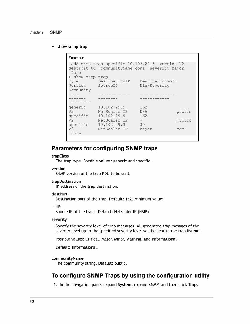
w show snmp trap
Example add snmp trap specific 10.102.29.3 -version V2 -destPort 80 -communityName com1 -severity Major Done> show snmp trapType DestinationIP DestinationPort Version SourceIP Min-Severity Community---- ------------- --------------- ------- -------- ------------ ---------generic 10.102.29.9 162 V2 NetScaler IP N/A publicspecific 10.102.29.9 162 V2 NetScaler IP - publicspecific 10.102.29.3 80 V2 NetScaler IP Major com1 Done
Parameters for configuring SNMP trapstrapClass
The trap type. Possible values: generic and specific.
versionSNMP version of the trap PDU to be sent.
trapDestinationIP address of the trap destination.
destPortDestination port of the trap. Default: 162. Minimum value: 1
scrIPSource IP of the traps. Default: NetScaler IP (NSIP)
severity
Specify the severity level of trap messages. All generated trap mesages of theseverity level up to the specified severity level will be sent to the trap listener.
Possible values: Critical, Major, Minor, Warning, and Informational.
Default: Informational.
communityNameThe community string. Default: public.
To configure SNMP Traps by using the configuration utility1. In the navigation pane, expand System, expand SNMP, and then click Traps.
Chapter 2 SNMP
52
2. In the details pane, do one of the following:
• To create a new trap, click Add.
• To modify an existing trap, select the trap, and then click Open.
3. In the Create SNMP Trap Destination or Configure SNMP Trap dialog box, specifyvalues for the following parameters, which correspond to parameters described in"Parameters for configuring SNMP traps" as shown:
• Type*—trapClass
• Version—version
• Destination IP Address*—trapDestination
• Destination Port—destPort
• Source IP Address—srcIP
• Minimum Severity—severity
• Community Name—communityName
*A required parameter
4. Click Create or OK, and then click Close.A message appears in the status bar, stating that the trap has been configuredsuccessfully.
Configuring the NetScaler for SNMP v1 and v2Queries
You can query the NetScaler SNMP agent for system-specific information from a remotedevice called SNMP managers. The agent then searches the management informationbase (MIB) for the data requested and sends the data to the SNMP manager.
The following types of SNMP v1 and v2 queries are suppoted by the SNMP agent:
w GET
w GET NEXT
w ALL
w GET BULK
You can create strings called community strings and associate each of these to querytypes. You can associate one or more community strings to each query type.Community string are passwords and used to authenticate SNMP queries from SNMPmanagers.
For example, if you associate two community strings, such as abc and bcd, to the querytype GET NEXT, the SNMP agent on the NetScaler appliance considers only those GETNEXT SNMP query packets that contain abc or bcd as the community string.
Citrix NetScaler Administration Guide
53
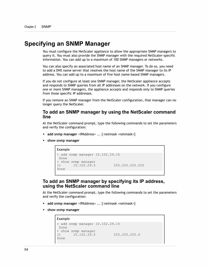
Specifying an SNMP ManagerYou must configure the NetScaler appliance to allow the appropriate SNMP managers toquery it. You must also provide the SNMP manager with the required NetScaler-specificinformation. You can add up to a maximum of 100 SNMP managers or networks.
You can also specify an associated host name of an SNMP manager. To do so, you needto add a DNS name server that resolves the host name of the SNMP manager to its IPaddress. You can add up to a maximum of five host name-based SNMP managers.
If you do not configure at least one SNMP manager, the NetScaler appliance acceptsand responds to SNMP queries from all IP addresses on the network. If you configureone or more SNMP managers, the appliance accepts and responds only to SNMP queriesfrom those specific IP addresses.
If you remove an SNMP manager from the NetScaler configuration, that manager can nolonger query the NetScaler.
To add an SNMP manager by using the NetScaler commandlineAt the NetScaler command prompt, type the following commands to set the parametersand verify the configuration:
w add snmp manager <IPAddress> ... [-netmask <netmask>]
w show snmp manager
Example> add snmp manager 10.102.29.10 Done> show snmp manager1) 10.102.29.5 255.255.255.255Done
To add an SNMP manager by specifying its IP address,using the NetScaler command lineAt the NetScaler command prompt, type the following commands to set the parametersand verify the configuration:
w add snmp manager <IPAddress> ... [-netmask <netmask>]
w show snmp manager
Example> add snmp manager 10.102.29.10 Done> show snmp manager1) 10.102.29.5 255.255.255.0Done
Chapter 2 SNMP
54
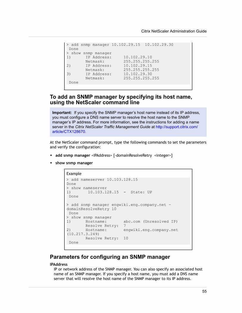
> add snmp manager 10.102.29.15 10.102.29.30 Done> show snmp manager1) IP Address: 10.102.29.10 Netmask: 255.255.255.2552) IP Address: 10.102.29.15 Netmask: 255.255.255.2553) IP Address: 10.102.29.30 Netmask: 255.255.255.255 Done
To add an SNMP manager by specifying its host name,using the NetScaler command line
Important: If you specify the SNMP manager’s host name instead of its IP address,you must configure a DNS name server to resolve the host name to the SNMPmanager’s IP address. For more information, see the instructions for adding a nameserver in the Citrix NetScaler Traffic Management Guide at http://support.citrix.com/article/CTX128670.
At the NetScaler command prompt, type the following commands to set the parametersand verify the configuration:
w add snmp manager <IPAddress> [-domainResolveRetry <integer>]
w show snmp manager
Example> add nameserver 10.103.128.15Done> show nameserver1) 10.103.128.15 - State: UP Done
> add snmp manager engwiki.eng.company.net –domainResolveRetry 10 Done> show snmp manager1) Hostname: abc.com (Unresolved IP) Resolve Retry: 72) Hostname: engwiki.eng.company.net (10.217.3.249) Resolve Retry: 10 Done
Parameters for configuring an SNMP managerIPAddress
IP or network address of the SNMP manager. You can also specify an associated hostname of an SNMP manager. If you specify a host name, you must add a DNS nameserver that will resolve the host name of the SNMP manager to its IP address.
Citrix NetScaler Administration Guide
55
netmaskSubnet of management stations. Used to grant access from entire subnets to theNetScaler appliance.
domainResolveRetryThe duration, in seconds, for which the NetScaler appliance waits to send the nextDNS query to resolve the host name of the SNMP manager if the last query failed. Iflast query succeeds, the NetScaler waits for the TTL time. Minimum value: 5.Maximum value: 20940. Default value: 5.
To add an SNMP manager by using the configuration utility1. In the navigation pane, expand System, expand SNMP, and then click Managers.
2. In the details pane, click Add.
3. In the Create SNMP Manager dialog box, specify values for the followingparameters, which correspond to parameters described in "Parameters forconfiguring an SNMP manager" as shown:
• IP Address*—IPAddress
• Netmask—netmask
*A required parameter
4. In the Create SNMP Manager dialog box, do one of the following:
• To specify the host name of an SNMP manager, select Management Host andspecify values for the following parameters, which correspond to parametersdescribed in "Parameters for configuring an SNMP manager" as shown:
w Host Name*—IPAddress
w Resolve Retry (secs)*—domainResolveRetry
Important: If you specify the SNMP manager’s host name instead of its IPaddress, you must configure a DNS name server to resolve the host name tothe SNMP manager’s IP address. For more information, see the instructionsfor adding a name server in the Citrix NetScaler Traffic Management Guide at http://support.citrix.com/article/CTX128670.
• To specify the IP address of an SNMP manager, select Management Network andspecify values for the following parameters, which correspond to parametersdescribed in "Parameters for configuring an SNMP manager" as shown:
w IP Address*—IPAddress
w Netmask—netmask
5. Click Create, and then click Close.A message appears in the status bar, stating that the SNMP manager has beenconfigured successfully.
Chapter 2 SNMP
56
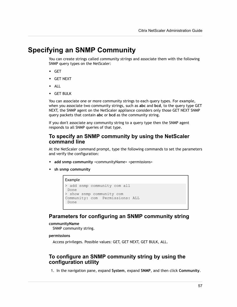
Specifying an SNMP CommunityYou can create strings called community strings and associate them with the followingSNMP query types on the NetScaler:
w GET
w GET NEXT
w ALL
w GET BULK
You can associate one or more community strings to each query types. For example,when you associate two community strings, such as abc and bcd, to the query type GETNEXT, the SNMP agent on the NetScaler appliance considers only those GET NEXT SNMPquery packets that contain abc or bcd as the community string.
If you don't associate any community string to a query type then the SNMP agentresponds to all SNMP queries of that type.
To specify an SNMP community by using the NetScalercommand lineAt the NetScaler command prompt, type the following commands to set the parametersand verify the configuration:
w add snmp community <communityName> <permissions>
w sh snmp community
Example> add snmp community com all Done> show snmp community comCommunity: com Permissions: ALL Done
Parameters for configuring an SNMP community stringcommunityName
SNMP community string.
permissions
Access privileges. Possible values: GET, GET NEXT, GET BULK, ALL.
To configure an SNMP community string by using theconfiguration utility1. In the navigation pane, expand System, expand SNMP, and then click Community.
Citrix NetScaler Administration Guide
57
2. In the details pane, click Add.
3. In the Create SNMP Community dialog box, specify values for the followingparameters, which correspond to parameters described in "Parameters forconfiguring an SNMP community string" as shown:
• Community String*—communityName
• Permission*—permissions
*A required parameter
4. Click Create, and then click Close.A message appears in the status bar, stating that the SNMP community string hasbeen configured successfully.
To remove an SNMP community string by using theconfiguration utility1. In the navigation pane, expand System, click SNMP, and then click Community.
2. In the details pane, select the community that you want to remove (for example,Com_All), and then click Remove.
Configuring SNMP Alarms for Rate LimitingCitrix® NetScaler® appliances such as the NetScaler MPX 10500, 12500, and 15500 arerate limited. The maximum throughput (Mbps) and packets per second (PPS) aredetermined by the license purchased for the appliance. For rate-limited platforms, youcan configure SNMP traps to send notifications when throughput and PPS approach theirlimits and when they return to normal.
Throughput and PPS are monitored every seven seconds. You can configure traps withhigh-threshold and normal-threshold values, which are expressed as a percentage ofthe licensed limits. The appliance then generates a trap when throughput or PPSexceeds the high threshold, and a second trap when the monitored parameter falls tothe normal threshold. In addition to sending the traps to the configured destinationdevice, the NetScaler logs the events associated with the traps in the /var/log/ns.log file as EVENT ALERTSTARTED and EVENT ALERTENDED.
Exceeding the throughput limit can result in packet loss. You can configure SNMPalarms to report packet loss.
For more information about SNMP alarms and traps, see Configuring the NetScaler toGenerate SNMPv1 and SNMPv2 Traps on page 48.
Configuring an SNMP Alarm for Throughput or PPSTo monitor both throughput and PPS, you must configure separate alarms.
Chapter 2 SNMP
58
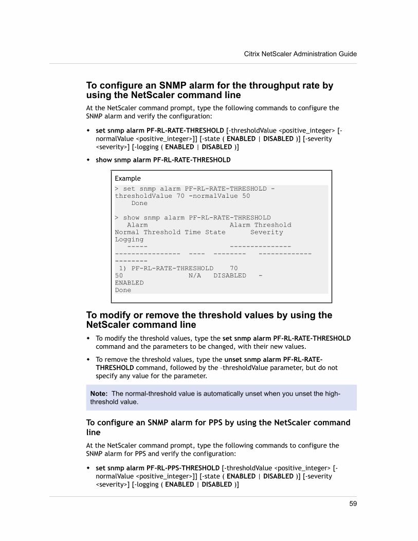
To configure an SNMP alarm for the throughput rate byusing the NetScaler command lineAt the NetScaler command prompt, type the following commands to configure theSNMP alarm and verify the configuration:
w set snmp alarm PF-RL-RATE-THRESHOLD [-thresholdValue <positive_integer> [-normalValue <positive_integer>]] [-state ( ENABLED | DISABLED )] [-severity<severity>] [-logging ( ENABLED | DISABLED )]
w show snmp alarm PF-RL-RATE-THRESHOLD
Example> set snmp alarm PF-RL-RATE-THRESHOLD -thresholdValue 70 -normalValue 50 Done
> show snmp alarm PF-RL-RATE-THRESHOLD Alarm Alarm Threshold Normal Threshold Time State Severity Logging ----- --------------- ---------------- ---- -------- ------------- -------- 1) PF-RL-RATE-THRESHOLD 70 50 N/A DISABLED - ENABLED Done
To modify or remove the threshold values by using theNetScaler command linew To modify the threshold values, type the set snmp alarm PF-RL-RATE-THRESHOLD
command and the parameters to be changed, with their new values.
w To remove the threshold values, type the unset snmp alarm PF-RL-RATE-THRESHOLD command, followed by the –thresholdValue parameter, but do notspecify any value for the parameter.
Note: The normal-threshold value is automatically unset when you unset the high-threshold value.
To configure an SNMP alarm for PPS by using the NetScaler commandlineAt the NetScaler command prompt, type the following commands to configure theSNMP alarm for PPS and verify the configuration:
w set snmp alarm PF-RL-PPS-THRESHOLD [-thresholdValue <positive_integer> [-normalValue <positive_integer>]] [-state ( ENABLED | DISABLED )] [-severity<severity>] [-logging ( ENABLED | DISABLED )]
Citrix NetScaler Administration Guide
59
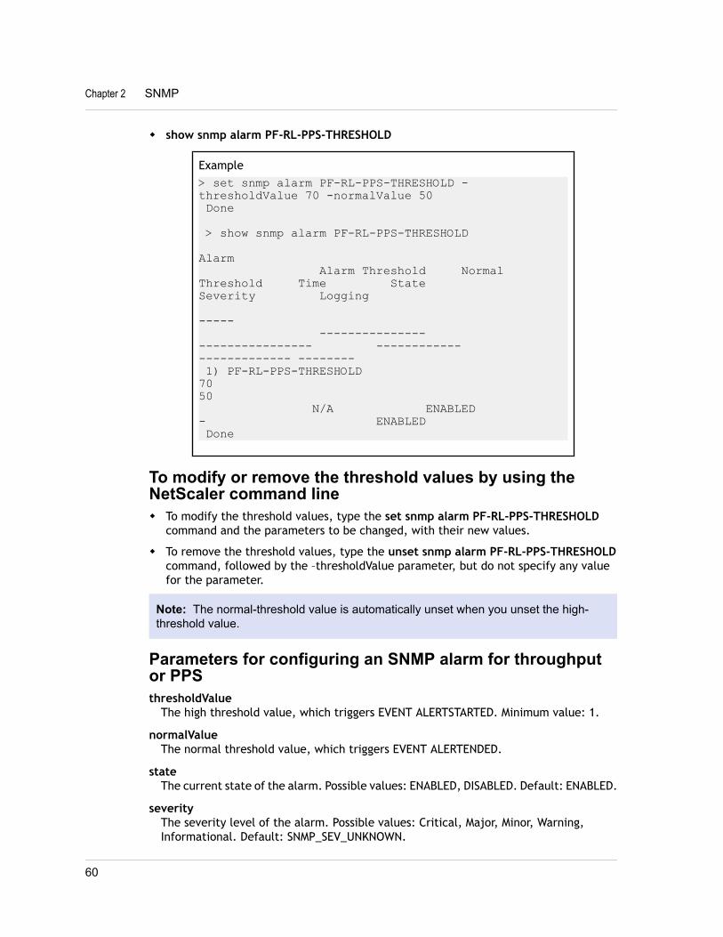
w show snmp alarm PF-RL-PPS-THRESHOLD
Example> set snmp alarm PF-RL-PPS-THRESHOLD -thresholdValue 70 -normalValue 50 Done
> show snmp alarm PF-RL-PPS-THRESHOLD Alarm Alarm Threshold Normal Threshold Time State Severity Logging ----- --------------- ---------------- ------------ ------------- -------- 1) PF-RL-PPS-THRESHOLD 70 50 N/A ENABLED - ENABLED Done
To modify or remove the threshold values by using theNetScaler command linew To modify the threshold values, type the set snmp alarm PF-RL-PPS-THRESHOLD
command and the parameters to be changed, with their new values.
w To remove the threshold values, type the unset snmp alarm PF-RL-PPS-THRESHOLDcommand, followed by the –thresholdValue parameter, but do not specify any valuefor the parameter.
Note: The normal-threshold value is automatically unset when you unset the high-threshold value.
Parameters for configuring an SNMP alarm for throughputor PPSthresholdValue
The high threshold value, which triggers EVENT ALERTSTARTED. Minimum value: 1.
normalValueThe normal threshold value, which triggers EVENT ALERTENDED.
stateThe current state of the alarm. Possible values: ENABLED, DISABLED. Default: ENABLED.
severityThe severity level of the alarm. Possible values: Critical, Major, Minor, Warning,Informational. Default: SNMP_SEV_UNKNOWN.
Chapter 2 SNMP
60
loggingLog the alarm. Possible values: ENABLED, DISABLED. Default value: ENABLED.
To configure an SNMP alarm for throughput or PPS byusing the configuration utility1. In the navigation pane, expand System, expand SNMP, and then click Alarms.
2. In the details pane, do one of the following:
• Select PF-RL-RATE-THRESHOLD to configure the SNMP alarm for throughput rate.
• Select PF-RL-PPS-THRESHOLD to configure the SNMP alarm for packets persecond.
3. Click Open.
4. In the Configure SNMP Alarm dialog box, specify values for the followingparameters, which correspond to parameters described in “Parameters forconfiguring an SNMP alarm for throughput or PPS” as shown:
• Alarm Threshold—thresholdValue
• Alarm Threshold—thresholdValue
• Normal Threshold—normalValue
• Severity—severity
• Logging—logging
5. Select the Enable check box to enable the alarm.
6. Click OK, and then click Close.
Configuring SNMP Alarm for Dropped PacketsYou can configure an alarm for packets dropped as a result of exceeding the throughputlimit and an alarm for packets dropped as a result of exceeding the PPS limit.
To configure an SNMP alarm for packets dropped becauseof excessive throughput, by using the NetScaler commandlineAt the NetScaler command prompt, type:
set snmp alarm PF-RL-RATE-PKTS-DROPPED [-state (ENABLED | DISABLED)] [-severity<severity>] [-logging ( ENABLED | DISABLED )]
To configure an SNMP alarm for packets dropped becauseof excessive PPS, by using the NetScaler command lineAt the NetScaler command prompt, type:
set snmp alarm PF-RL-PPS-PKTS-DROPPED [-state (ENABLED | DISABLED)] [-severity<severity>] [-logging ( ENABLED | DISABLED )]
Citrix NetScaler Administration Guide
61
Parameters for configuring an SNMP alarm for droppedpacketsstate
The current state of the alarm. Possible values: ENABLED, DISABLED. Default: ENABLED.
severityThe severity level of the alarm. Possible values: Critical, Major, Minor, Warning,Informational. Default: SNMP_SEV_UNKNOWN.
loggingLog the alarm. Possible values: ENABLED, DISABLED. Default value: ENABLED.
To configure an SNMP alarm for dropped packets by usingthe configuration utility1. In the navigation pane, expand System, expand SNMP, and then click Alarms.
2. In the details pane, do one of the following:
• Select PF-RL-RATE-PKTS-DROPPED to configure an SNMP alarm for packetsdropped because of excessive throughput.
• Select PF-RL-PPS-PKTS-DROPPED to configure an SNMP alarm for packetsdropped because of excessive PPS.
3. Click Open.
4. In the Configure SNMP Alarm dialog box, specify values for the followingparameters, which correspond to parameters described in “Parameters forconfiguring an SNMP alarm for dropped packets” as shown:
• Severity—severity
• Logging—logging
5. Select the Enable check box to enable the alarm.
6. Click OK, and then click Close.
Configuring the NetScaler for SNMPv3 QueriesSimple Network Management Protocol Version 3 (SNMPv3) is based on the basicstructure and architecture of SNMPv1 and SNMPv2. However, SNMPv3 enhances thebasic architecture to incorporate administration and security capabilities, such asauthentication, access control, data integrity check, data origin verification, messagetimeliness check, and data confidentiality.
To implement message level security and access control, SNMPv3 introduces the user-based security model (USM) and the view-based access control model (VACM).
w User-Based Security Model. The user-based security model (USM) provides message-level security. It enables you to configure users and security parameters for theSNMP agent and the SNMP manager. USM offers the following features:
Chapter 2 SNMP
62
• Data integrity: To protect messages from being modified during transmissionthrough the network.
• Data origin verification: To authenticate the user who sent the message request.
• Message timeliness: To protect against message delays or replays.
• Data confidentiality: To protect the content of messages from being disclosed tounauthorized entities or individuals.
w View-Based Access Control Model. The view-based access control model (VACM)enables you to configure access rights to a specific subtree of the MIB based onvarious parameters, such as security level, security model, user name, and viewtype. It enables you to configure agents to provide different levels of access to theMIB to different managers.
The Citrix NetScaler supports the following entities that enable you to implement thesecurity features of SNMPv3:
w SNMP Engines
w SNMP Views
w SNMP Groups
w SNMP Users
These entities function together to implement the SNMPv3 security features. Views arecreated to allow access to subtrees of the MIB. Then, groups are created with therequired security level and access to the defined views. Finally, users are created andassigned to the groups.
Note: The view, group, and user configuration are synchronized and propagated tothe secondary node in a high availability (HA) pair. However, the engine ID is neitherpropagated nor synchronized as it is unique to each NetScaler appliance.
To implement message authentication and access control, you need to:
w Set the Engine ID
w Configure Views
w Configure Groups
w Configure Users
Setting the Engine IDSNMP engines are service providers that reside in the SNMP agent. They provideservices such as sending, receiving, and authenticating messages. SNMP engines areuniquely identified using engine IDs.
The NetScaler has a unique engineID based on the MAC address of one of its interfaces.It is not necessary to override the engineID. However, if you want to change the engineID, you can reset it.
Citrix NetScaler Administration Guide
63
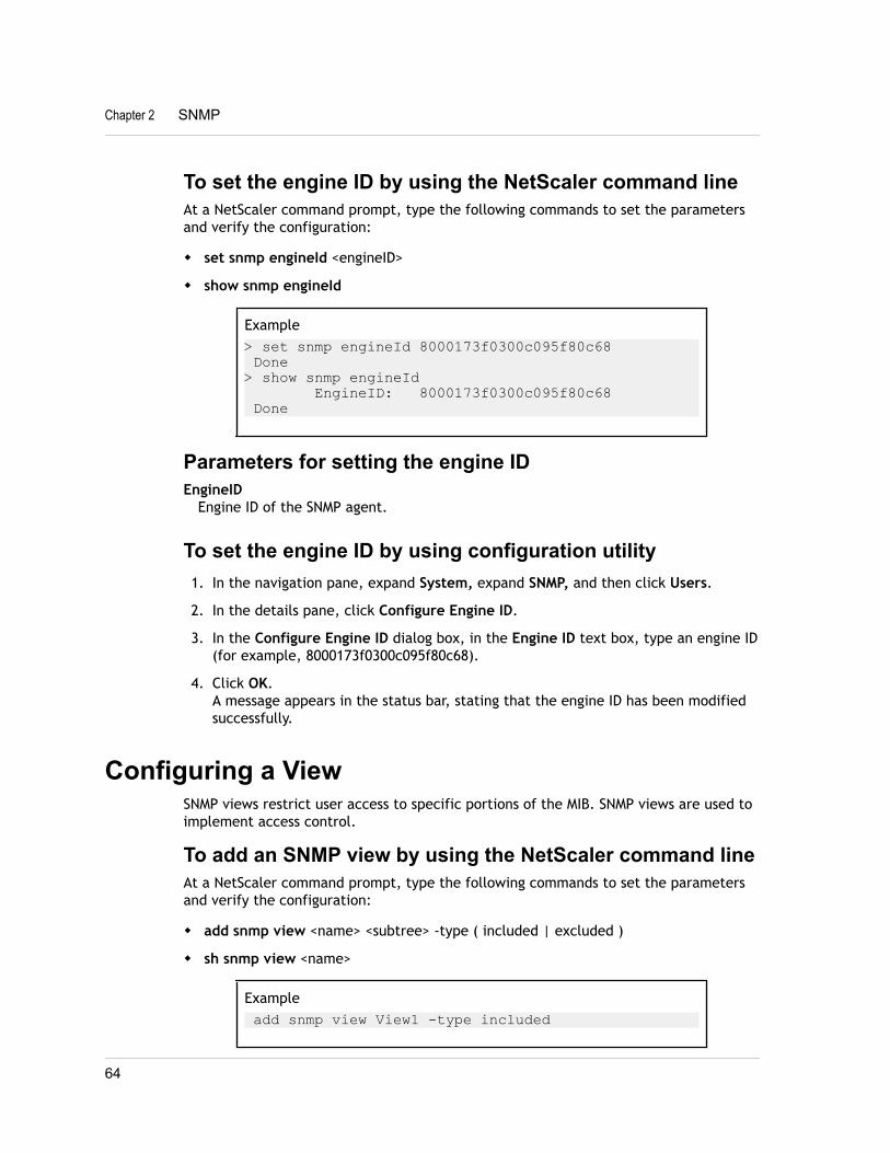
To set the engine ID by using the NetScaler command lineAt a NetScaler command prompt, type the following commands to set the parametersand verify the configuration:
w set snmp engineId <engineID>
w show snmp engineId
Example> set snmp engineId 8000173f0300c095f80c68 Done> show snmp engineId EngineID: 8000173f0300c095f80c68 Done
Parameters for setting the engine IDEngineID
Engine ID of the SNMP agent.
To set the engine ID by using configuration utility1. In the navigation pane, expand System, expand SNMP, and then click Users.
2. In the details pane, click Configure Engine ID.
3. In the Configure Engine ID dialog box, in the Engine ID text box, type an engine ID(for example, 8000173f0300c095f80c68).
4. Click OK.A message appears in the status bar, stating that the engine ID has been modifiedsuccessfully.
Configuring a ViewSNMP views restrict user access to specific portions of the MIB. SNMP views are used toimplement access control.
To add an SNMP view by using the NetScaler command lineAt a NetScaler command prompt, type the following commands to set the parametersand verify the configuration:
w add snmp view <name> <subtree> -type ( included | excluded )
w sh snmp view <name>
Example add snmp view View1 -type included
Chapter 2 SNMP
64
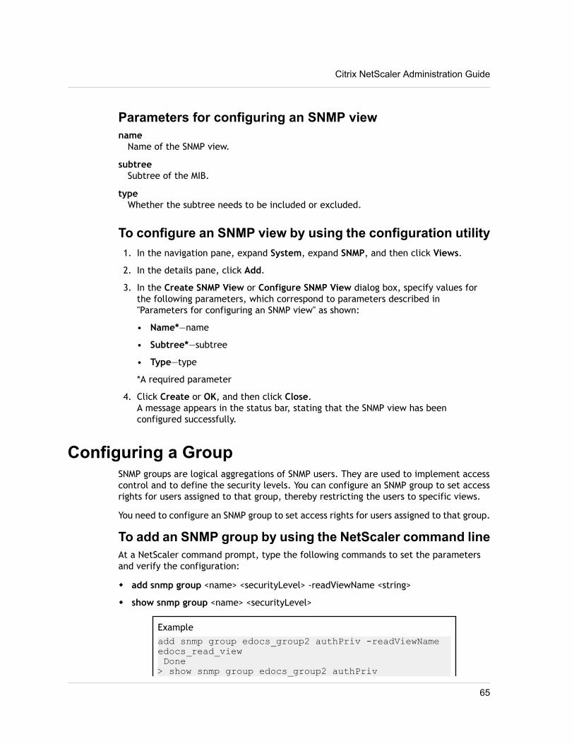
Parameters for configuring an SNMP viewname
Name of the SNMP view.
subtreeSubtree of the MIB.
typeWhether the subtree needs to be included or excluded.
To configure an SNMP view by using the configuration utility1. In the navigation pane, expand System, expand SNMP, and then click Views.
2. In the details pane, click Add.
3. In the Create SNMP View or Configure SNMP View dialog box, specify values forthe following parameters, which correspond to parameters described in"Parameters for configuring an SNMP view" as shown:
• Name*—name
• Subtree*—subtree
• Type—type
*A required parameter
4. Click Create or OK, and then click Close.A message appears in the status bar, stating that the SNMP view has beenconfigured successfully.
Configuring a GroupSNMP groups are logical aggregations of SNMP users. They are used to implement accesscontrol and to define the security levels. You can configure an SNMP group to set accessrights for users assigned to that group, thereby restricting the users to specific views.
You need to configure an SNMP group to set access rights for users assigned to that group.
To add an SNMP group by using the NetScaler command lineAt a NetScaler command prompt, type the following commands to set the parametersand verify the configuration:
w add snmp group <name> <securityLevel> -readViewName <string>
w show snmp group <name> <securityLevel>
Exampleadd snmp group edocs_group2 authPriv -readViewName edocs_read_view Done> show snmp group edocs_group2 authPriv
Citrix NetScaler Administration Guide
65
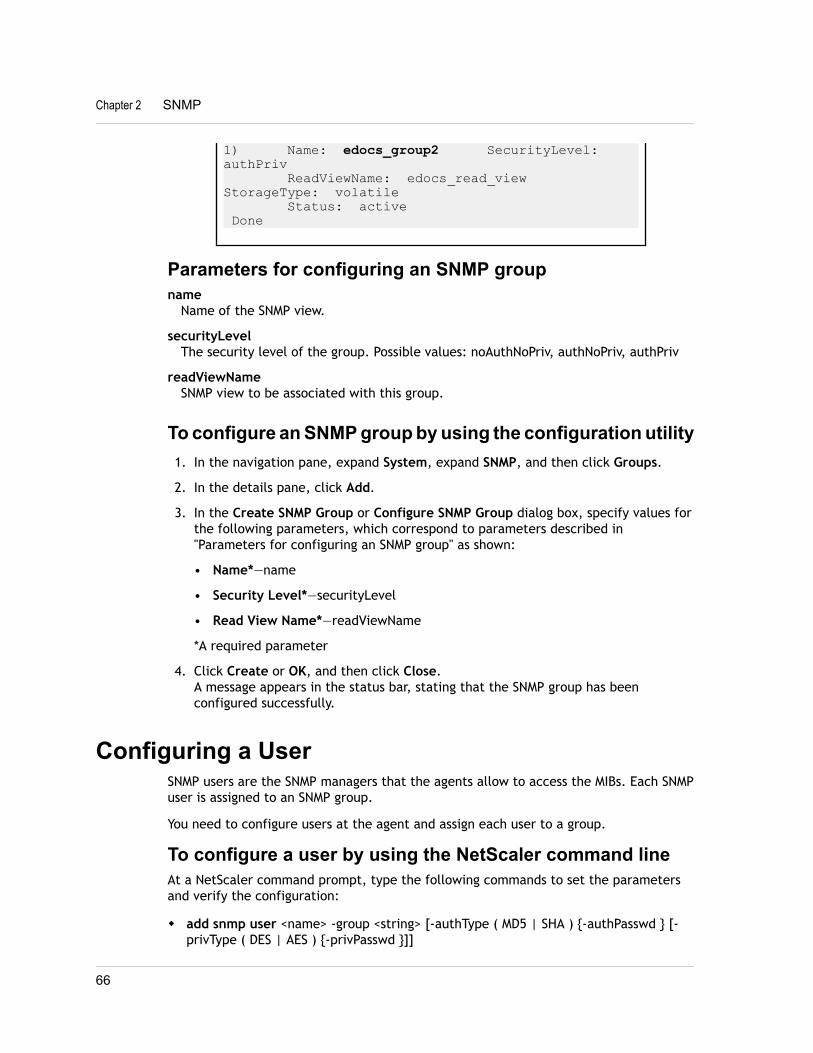
1) Name: edocs_group2 SecurityLevel: authPriv ReadViewName: edocs_read_view StorageType: volatile Status: active Done
Parameters for configuring an SNMP groupname
Name of the SNMP view.
securityLevelThe security level of the group. Possible values: noAuthNoPriv, authNoPriv, authPriv
readViewNameSNMP view to be associated with this group.
To configure an SNMP group by using the configuration utility1. In the navigation pane, expand System, expand SNMP, and then click Groups.
2. In the details pane, click Add.
3. In the Create SNMP Group or Configure SNMP Group dialog box, specify values forthe following parameters, which correspond to parameters described in"Parameters for configuring an SNMP group" as shown:
• Name*—name
• Security Level*—securityLevel
• Read View Name*—readViewName
*A required parameter
4. Click Create or OK, and then click Close.A message appears in the status bar, stating that the SNMP group has beenconfigured successfully.
Configuring a UserSNMP users are the SNMP managers that the agents allow to access the MIBs. Each SNMPuser is assigned to an SNMP group.
You need to configure users at the agent and assign each user to a group.
To configure a user by using the NetScaler command lineAt a NetScaler command prompt, type the following commands to set the parametersand verify the configuration:
w add snmp user <name> -group <string> [-authType ( MD5 | SHA ) {-authPasswd } [-privType ( DES | AES ) {-privPasswd }]]
Chapter 2 SNMP
66
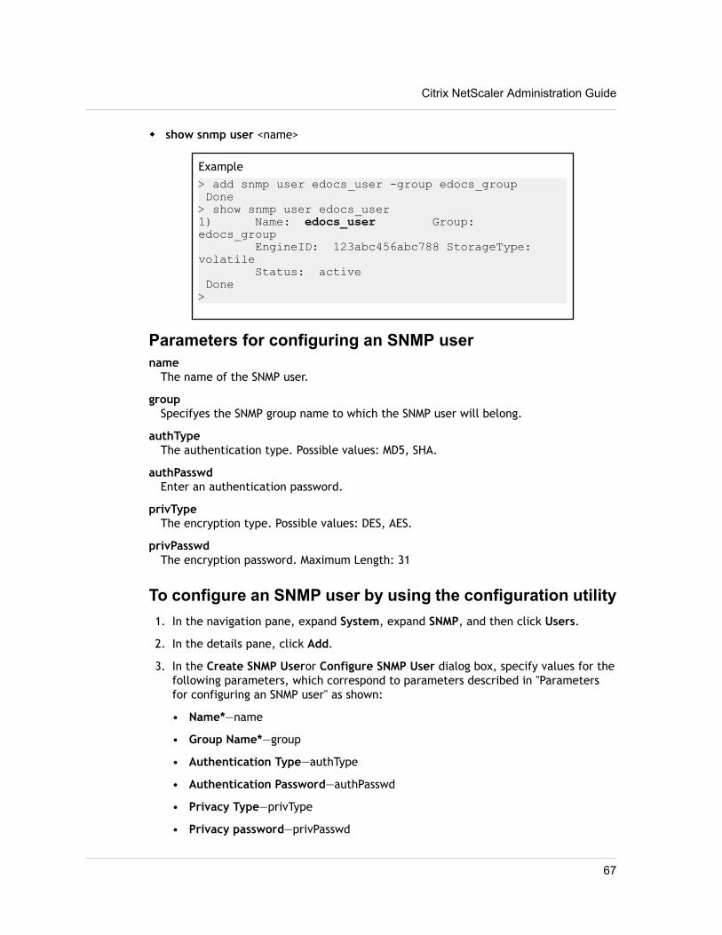
w show snmp user <name>
Example> add snmp user edocs_user -group edocs_group Done> show snmp user edocs_user1) Name: edocs_user Group: edocs_group EngineID: 123abc456abc788 StorageType: volatile Status: active Done>
Parameters for configuring an SNMP username
The name of the SNMP user.
groupSpecifyes the SNMP group name to which the SNMP user will belong.
authTypeThe authentication type. Possible values: MD5, SHA.
authPasswdEnter an authentication password.
privTypeThe encryption type. Possible values: DES, AES.
privPasswdThe encryption password. Maximum Length: 31
To configure an SNMP user by using the configuration utility1. In the navigation pane, expand System, expand SNMP, and then click Users.
2. In the details pane, click Add.
3. In the Create SNMP Useror Configure SNMP User dialog box, specify values for thefollowing parameters, which correspond to parameters described in "Parametersfor configuring an SNMP user" as shown:
• Name*—name
• Group Name*—group
• Authentication Type—authType
• Authentication Password—authPasswd
• Privacy Type—privType
• Privacy password—privPasswd
Citrix NetScaler Administration Guide
67
*A required parameter
4. Click Create or OK, and then click Close.A message appears in the status bar, stating that the SNMP user has beenconfigured successfully.
Chapter 2 SNMP
68
Chapter 3
Audit Logging
Topics:• Configuring the NetScaler
Appliance for Audit Logging
• Installing and Configuringthe NSLOG Server
• Running the NSLOG Server
• Customizing Logging on theNSLOG Server
• Default Settings for the LogProperties
• Sample Configuration File(audit.conf)
Auditing is a methodical examination or review of a conditionor situation. The Audit Logging feature enables you to log theCitrix® NetScaler® states and status information collected byvarious modules in the kernel and in the user-level daemons.For audit logging, you have the options to configure SYSLOG,the native NSLOG protocol, or both.
SYSLOG is a standard protocol for logging. It has twocomponents─ the SYSLOG auditing module, which runs on theNetScaler appliance, and the SYSLOG server, which can run onthe underlying FreeBSD operating system (OS) of theNetScaler appliance or on a remote system. SYSLOG uses userdata protocol (UDP) for the transfer of data.
Similarly, the native NSLOG protocol has two components─ theNSLOG auditing module, which runs on the NetScalerappliance, and the NSLOG server, which can run on theunderlying FreeBSD OS of the NetScaler appliance or on aremote system. NSLOG uses transmission control protocol(TCP) for transfer of data.
When you run NSLOG or a SYSLOG server, it connects to theNetScaler appliance. The NetScaler appliance then startssending all the log information to the SYSLOG or NSLOGserver, and the server can filter the log entries before storingthem in a log file. An NSLOG or SYSLOG server can receive loginformation from more than one NetScaler appliance and aNetScaler appliance can send log information to more thanone SYSLOG server or NSLOG server.
The log information that a SYSLOG or NSLOG server collectsfrom a NetScaler appliance is stored in a log file in the formof messages. These messages typically contain the followinginformation:
w The IP address of a NetScaler appliance that generated thelog message
w A time stamp
w The message type
w The predefined log levels (Critical, Error, Notice, Warning,Informational, Debug, Alert, and Emergency)
w The message information
69
To configure audit logging, you first configure the auditmodules on the NetScaler that involves creating audit policiesand specifying the NSLOG server or SYSLOG serverinformation. You then install and configure the SYSLOG or theNSLOG server on the underlying FreeBSD OS of the NetScalerappliance or on a remote system.
Note: Because SYSLOG is an industry standard for loggingprogram messages and because various vendors providesupport, this documentation does not include SYSLOGserver configuration information.
The NSLOG server has it own configuration file(auditlog.conf). You can customize logging on the NSLOGserver system by making additional modifications to theconfiguration file (auditlog.conf).
Chapter 3 Audit Logging
70
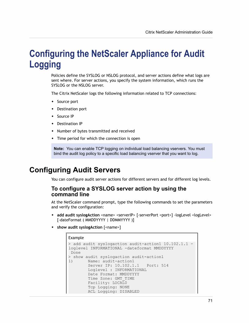
Configuring the NetScaler Appliance for AuditLogging
Policies define the SYSLOG or NSLOG protocol, and server actions define what logs aresent where. For server actions, you specify the system information, which runs theSYSLOG or the NSLOG server.
The Citrix NetScaler logs the following information related to TCP connections:
w Source port
w Destination port
w Source IP
w Destination IP
w Number of bytes transmitted and received
w Time period for which the connection is open
Note: You can enable TCP logging on individual load balancing vservers. You mustbind the audit log policy to a specific load balancing vserver that you want to log.
Configuring Audit ServersYou can configure audit server actions for different servers and for different log levels.
To configure a SYSLOG server action by using thecommand lineAt the NetScaler command prompt, type the following commands to set the parametersand verify the configuration:
w add audit syslogAction <name> <serverIP> [-serverPort <port>] -logLevel <logLevel>[-dateFormat ( MMDDYYYY | DDMMYYYY )]
w show audit syslogAction [<name>]
Example> add audit syslogaction audit-action1 10.102.1.1 -loglevel INFORMATIONAL -dateformat MMDDYYYY Done> show audit syslogaction audit-action11) Name: audit-action1 Server IP: 10.102.1.1 Port: 514 Loglevel : INFORMATIONAL Date Format: MMDDYYYY Time Zone: GMT_TIME Facility: LOCAL0 Tcp Logging: NONE ACL Logging: DISABLED
Citrix NetScaler Administration Guide
71
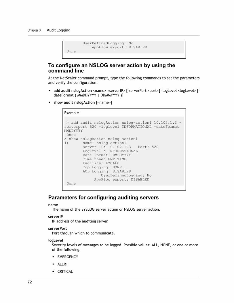
UserDefinedLogging: No AppFlow export: DISABLED Done
To configure an NSLOG server action by using thecommand lineAt the NetScaler command prompt, type the following commands to set the parametersand verify the configuration:
w add audit nslogAction <name> <serverIP> [-serverPort <port>] -logLevel <logLevel> [-dateFormat ( MMDDYYYY | DDMMYYYY )]
w show audit nslogAction [<name>]
Example
> add audit nslogAction nslog-action1 10.102.1.3 -serverport 520 -loglevel INFORMATIONAL -dateFormat MMDDYYYY Done> show nslogAction nslog-action11) Name: nslog-action1 Server IP: 10.102.1.3 Port: 520 Loglevel : INFORMATIONAL Date Format: MMDDYYYY Time Zone: GMT_TIME Facility: LOCAL0 Tcp Logging: NONE ACL Logging: DISABLED UserDefinedLogging: No AppFlow export: DISABLED Done
Parameters for configuring auditing serversname
The name of the SYSLOG server action or NSLOG server action.
serverIPIP address of the auditing server.
serverPortPort through which to communicate.
logLevelSeverity levels of messages to be logged. Possible values: ALL, NONE, or one or moreof the following:
w EMERGENCY
w ALERT
w CRITICAL
Chapter 3 Audit Logging
72
w ERROR
w WARNING
w NOTICE
w INFORMATION
w DEBUG
dateFormatFormat of the date stamp. Possible values: MMDDYYYY, DDMMYYYY.
logFacilityThe Facility value (RFC 3164) assigned to the log message. Uses numerical codes 0 to7 to indicate the type of message originating from the NetScaler (for example, NSand VPN). Possible values: LOCAL0 to LOCAL7. Default: LOCAL0.
timeZoneTime zone for the time stamp. Possible values: GMT and Local. Default: Local.
tcpLog TCP events. Possible values: NONE, ALL.
aclLog ACL events. Possible values: ENABLED, DISABLED.
userDefinedAuditlogEnable user-configurable log messages. Possible values: YES, NO.
appflowExportExport log messages to the AppFlow collectors. Possible values: ENABLED, DISABLED.Default: DISABLED.
Log levels definedEMERGENCY
Log errors indicating that the NetScaler is experiencing a critical problem that maymake it unusable.
ALERTLog problems that are not critical to current operations but that indicate a need forimmediate corrective action to prevent a critical problem.
CRITICALLog critical conditions, which do not restrict current operations but may escalate toa larger problem.
ERRORLog messages related to failed NetScaler operations.
WARNINGLog issues that may result in critical errors.
NOTICELog events specified by the INFORMATION setting, but in greater detail.
Citrix NetScaler Administration Guide
73
INFORMATIONLog actions taken by the NetScaler. This level is useful for troubleshooting problems.
DEBUGLog extensive, detailed information to help developers troubleshoot problems.
To configure an auditing server action1. In the navigation pane, expand System, expand Auditing, and then click Policies.
2. In the details pane, on the Servers tab, do one of the following:
• To create a new server action, click Add.
• To modify an existing server action, select the server, and then click Open.
3. In the Create Auditing Server or Configure Auditing Server dialog box, specifyvalues for the following parameters, which correspond to parameters described in"Parameters for configuring auditing servers" as shown:
• Name*—name
• IP Address*—serverIP
• Port—serverPort
• Log Levels—logLevel
• Log Facility—logFacility
• Date format—dateFormat
• Time Zone—timeZone
• TCP Logging—tcp
• ACL Logging—acl
• User Configurable Log Messages—userDefinedAuditlog
• AppFlow Export—appflowExport
*A required parameter
4. Click Create or OK, and then click Close.A message appears in the status bar, stating that the auditing server has beenconfigured successfully.
Configuring Audit PoliciesThe audit policies define the SYSLOG or NSLOG protocol.
To configure a SYSLOG policy by using the command lineAt the NetScaler command prompt, type the following commands to set the parametersand verify the configuration:
Chapter 3 Audit Logging
74
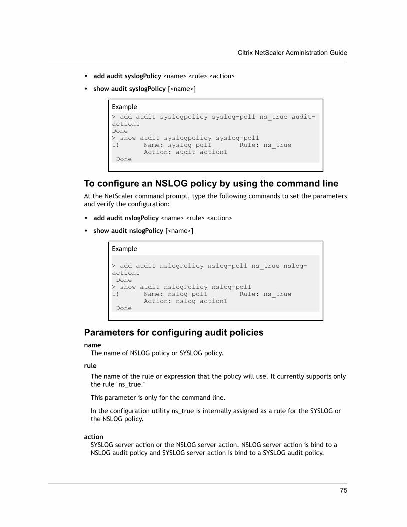
w add audit syslogPolicy <name> <rule> <action>
w show audit syslogPolicy [<name>]
Example> add audit syslogpolicy syslog-pol1 ns_true audit-action1 Done> show audit syslogpolicy syslog-pol11) Name: syslog-pol1 Rule: ns_true Action: audit-action1 Done
To configure an NSLOG policy by using the command lineAt the NetScaler command prompt, type the following commands to set the parametersand verify the configuration:
w add audit nslogPolicy <name> <rule> <action>
w show audit nslogPolicy [<name>]
Example
> add audit nslogPolicy nslog-pol1 ns_true nslog-action1 Done> show audit nslogPolicy nslog-pol11) Name: nslog-pol1 Rule: ns_true Action: nslog-action1 Done
Parameters for configuring audit policiesname
The name of NSLOG policy or SYSLOG policy.
rule
The name of the rule or expression that the policy will use. It currently supports onlythe rule "ns_true."
This parameter is only for the command line.
In the configuration utility ns_true is internally assigned as a rule for the SYSLOG orthe NSLOG policy.
actionSYSLOG server action or the NSLOG server action. NSLOG server action is bind to aNSLOG audit policy and SYSLOG server action is bind to a SYSLOG audit policy.
Citrix NetScaler Administration Guide
75
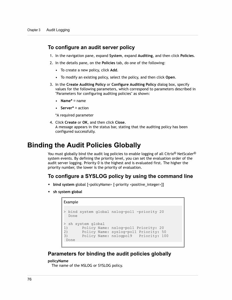
To configure an audit server policy1. In the navigation pane, expand System, expand Auditing, and then click Policies.
2. In the details pane, on the Policies tab, do one of the following:
• To create a new policy, click Add.
• To modify an existing policy, select the policy, and then click Open.
3. In the Create Auditing Policy or Configure Auditing Policy dialog box, specifyvalues for the following parameters, which correspond to parameters described in"Parameters for configuring auditing policies" as shown:
• Name* ─ name
• Server* ─ action
*A required parameter
4. Click Create or OK, and then click Close.A message appears in the status bar, stating that the auditing policy has beenconfigured successfully.
Binding the Audit Policies GloballyYou must globally bind the audit log policies to enable logging of all Citrix® NetScaler®
system events. By defining the priority level, you can set the evaluation order of theaudit server logging. Priority 0 is the highest and is evaluated first. The higher thepriority number, the lower is the priority of evaluation.
To configure a SYSLOG policy by using the command linew bind system global [<policyName> [-priority <positive_integer>]]
w sh system global
Example
> bind system global nslog-pol1 -priority 20 Done
> sh system global1) Policy Name: nslog-pol1 Priority: 202) Policy Name: syslog-pol1 Priority: 503) Policy Name: nslogpol9 Priority: 100 Done
Parameters for binding the audit policies globallypolicyName
The name of the NSLOG or SYSLOG policy.
Chapter 3 Audit Logging
76
priorityA numeric value that indicates when this policy is evaluated relative to others. Alower priority is evaluated before a higher one.
To globally bind the audit policy1. In the navigation pane, expand System, expand Auditing, and then click Policies.
2. In the details pane, on the Policies tab, click Global Bindings.
3. In the Bind/Unbind Auditing Global Policies dialog box, click Insert Policy.
4. Select the policy from the drop-down list that appears under Policy Name, andthen click OK.A message appears in the status bar, stating that the auditing policy has beenglobally bound.
Configuring Policy-Based LoggingYou can configure policy-based logging for rewrite and responder policies. Auditmessages are then logged in a defined format when the rule in a policy evaluates toTRUE. To configure policy-based logging, you configure an audit-message action thatuses default syntax expressions to specify the format of the audit messages, andassociate the action with a policy. The policy can be bound either globally or to a loadbalancing or content switching virtual server. You can use audit-message actions to logmessages at various log levels, either in syslog format only or in both syslog andnewnslog formats.
Pre Requisitesw User Configurable Log Messages (userDefinedAuditlog) option is enabled for when
configuring the audit action server to which you want to send the logs in a definedformat. For more information about enabling policy-based logging on a audit actionserver, see http://support.citrix.com/proddocs/topic/netscaler-admin-guide-93/ns-ag-bind-adt-pol-tsk.html.
w The related audit policy is bound to system global. For more information aboutbinding audit policies to system global, see http://support.citrix.com/proddocs/topic/netscaler-admin-guide-93/ns-ag-bind-adt-pol-tsk.html.
Configuring an Audit Message ActionYou can configure audit message actions to log messages at various log levels, either insyslog format only or in both syslog and newnslog formats. Audit-message actions useexpressions to specify the format of the audit messages.
To create an audit message action by using the NetScaler command lineAt the NetScaler command prompt, type:
add audit messageaction <name> <logLevel> <stringBuilderExpr> [-logtoNewnslog (YES|NO)] [-bypassSafetyCheck (YES|NO)]
Citrix NetScaler Administration Guide
77
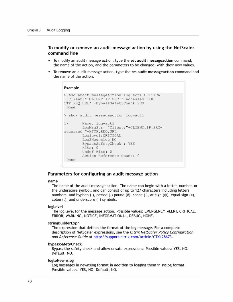
To modify or remove an audit message action by using the NetScalercommand linew To modify an audit message action, type the set audit messageaction command,
the name of the action, and the parameters to be changed, with their new values.
w To remove an audit message action, type the rm audit messageaction command andthe name of the action.
Example
> add audit messageaction log-act1 CRITICAL '"Client:"+CLIENT.IP.SRC+" accessed "+HTTP.REQ.URL' -bypassSafetyCheck YES Done
> show audit messageaction log-act1
1) Name: log-act1 LogMsgStr: "Client:"+CLIENT.IP.SRC+" accessed "+HTTP.REQ.URL Loglevel:CRITICAL Log2Newnslog:NO BypassSafetyCheck : YES Hits: 0 Undef Hits: 0 Action Reference Count: 0 Done
Parameters for configuring an audit message actionname
The name of the audit message action. The name can begin with a letter, number, orthe underscore symbol, and can consist of up to 127 characters including letters,numbers, and hyphen (-), period (.) pound (#), space ( ), at sign (@), equal sign (=),colon (:), and underscore (_) symbols.
logLevelThe log level for the message action. Possible values: EMERGENCY, ALERT, CRITICAL,ERROR, WARNING, NOTICE, INFORMATIONAL, DEBUG, NONE.
stringBuilderExprThe expression that defines the format of the log message. For a completedescription of NetScaler expressions, see the Citrix NetScaler Policy Configurationand Reference Guide at http://support.citrix.com/article/CTX128673.
bypassSafetyCheckBypass the safety check and allow unsafe expressions. Possible values: YES, NO.Default: NO.
logtoNewnslogLog messages in newnslog format in addition to logging them in syslog format.Possible values: YES, NO. Default: NO.
Chapter 3 Audit Logging
78
To configure an audit message action by using the configuration utility
1. In the navigation pane, expand System, expand Auditing, and then click MessageActions.
2. In the details pane, do one of the following:
• To create a new audit message action, click Add.
• To modify an existing audit message action, select the action, and then clickOpen.
3. In the Create Message Action or Configure Message Action dialog box, specifyvalues for the following parameters, which correspond to parameters described in“Parameters for configuring an audit message action” as shown:
• Name*—name
• Log Level*—logLevel
• Log Message—stringBuilderExpr
• Bypass Safety Check—bypassSafetyCheck (To specify YES, select the check box.)
• Log in newnslog—logtoNewnslog (To specify YES, select the check box.)
*A required parameter
4. Click Create or OK, and then click Close. The audit message action that youconfigured appears in the details pane.
Binding Audit Message Action to a PolicyAfter you have created an audit message action, you must bind it to a rewrite orresponder policy. For more information about binding log message actions to a rewriteor responder policy, see the "Rewrite" or the "Responder" chapter of the CitrixNetScaler Application Security Guide at http://support.citrix.com/article/CTX128674.
Installing and Configuring the NSLOG ServerDuring installation, the NSLOG server executable file (auditserver) is installed alongwith other files. The auditserver executable file includes options for performing severalactions on the NSLOG server, including running and stopping the NSLOG server. Inaddition, you use the auditserver executable to configure the NSLOG server with the IPaddresses of the NetScaler appliances from which the NSLOG server will start collectinglogs. Configuration settings are applied in the NSLOG server configuration file(auditlog.conf).
Then, you start the NSLOG server by executing the auditserver executable. The NSLOGserver configuration is based on the settings in the configuration file. You can furthercustomize logging on the NSLOG server system by making additional modifications tothe NSLOG server configuration file (auditlog.conf).
The following table lists the operating systems on which the NSLOG server is supported.
Citrix NetScaler Administration Guide
79
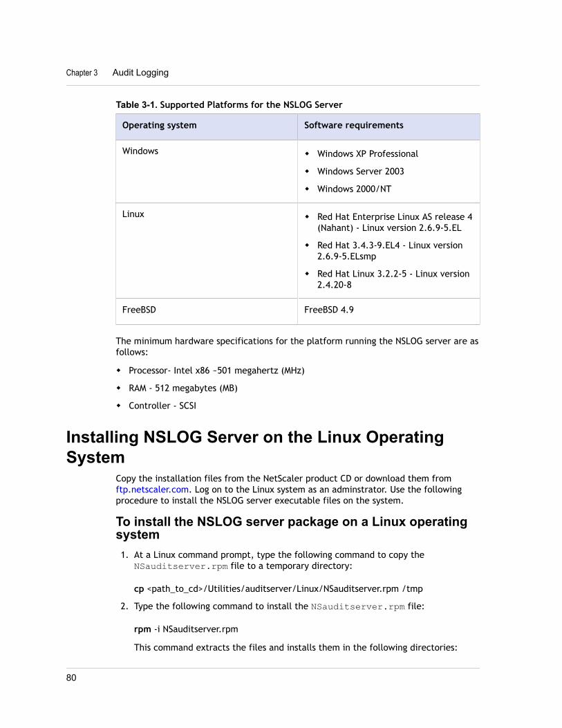
Table 3-1. Supported Platforms for the NSLOG Server
Operating system Software requirements
Windows w Windows XP Professional
w Windows Server 2003
w Windows 2000/NT
Linux w Red Hat Enterprise Linux AS release 4(Nahant) - Linux version 2.6.9-5.EL
w Red Hat 3.4.3-9.EL4 - Linux version2.6.9-5.ELsmp
w Red Hat Linux 3.2.2-5 - Linux version2.4.20-8
FreeBSD FreeBSD 4.9
The minimum hardware specifications for the platform running the NSLOG server are asfollows:
w Processor- Intel x86 ~501 megahertz (MHz)
w RAM - 512 megabytes (MB)
w Controller - SCSI
Installing NSLOG Server on the Linux OperatingSystem
Copy the installation files from the NetScaler product CD or download them from ftp.netscaler.com. Log on to the Linux system as an adminstrator. Use the followingprocedure to install the NSLOG server executable files on the system.
To install the NSLOG server package on a Linux operatingsystem1. At a Linux command prompt, type the following command to copy the
NSauditserver.rpm file to a temporary directory:
cp <path_to_cd>/Utilities/auditserver/Linux/NSauditserver.rpm /tmp
2. Type the following command to install the NSauditserver.rpm file:
rpm -i NSauditserver.rpm
This command extracts the files and installs them in the following directories:
Chapter 3 Audit Logging
80
• /usr/local/netscaler/etc• /usr/local/netscaler/bin• /usr/local/netscaler/samples
To uninstall the NSLOG server package on a Linuxoperating system1. At a command prompt, type the following command to uninstall the audit server
logging feature:
rpm -e NSauditserver
2. For more information about the NSauditserver RPM file, use the following command:
rpm -qpi *.rpm
3. To view the installed audit server files use the following command:
rpm -qpl *.rpm
*.rpm: Specifies the file name.
Installing NSLOG Server on the FreeBSD OperatingSystem
Copy the installation files from the NetScaler product CD or download them from ftp.netscaler.com. Log on to the FreeBSD operating system as an adminstrator. Use thefollowing procedure to install the NSLOG server executable files on the system.
Note: If you want to install the NSLOG server on the underlying FreeBSD OS of theNetScaler appliance, then log on to the NetScaler appliance's command line and thenswitch to the shell prompt and then use the following procedure.
To install the NSLOG server package on a FreeBSDoperating system1. Copy the NSauditserver.tgz file to a target directory by using the following command:
cp <path_to_cd>/Utilities/auditserver/Freebsd/NSauditserver.tgz /<targetdirectory>
2. Change to the target directory:
cd / <targetdirectory>
3. Use the following command to install the package:
pkg_add NSauditserver.tgz
This command extracts the files and installs them in the following directories:
Citrix NetScaler Administration Guide
81
• /usr/local/netscaler/etc• /usr/local/netscaler/bin• /usr/local/netscaler/samples
4. At a command prompt, type the following command to check whether the packageis installed:
pkg_info | grep NSauditserver
To uninstall the NSLOG server package on a FreeBSDoperating systemAt a command prompt, type:
pkg_delete NSauditserver
Installing NSLOG Server Files on the WindowsOperating System
You need to copy the NSLOG package from the NetScaler product CD or download itfrom www.citrix.com. The NSLOG package has the following name format AuditServer_<release number>-<build number>.zip (for example, AuditServer_9.3-51.5.zip ). Thispackage contains NSLOG installation packages for all the supported platforms.
To download NSLOG package from www.Citrix.com1. From any system, open www.citrix.com in the Web browser.
2. In the menu bar, click Log In.
3. Enter your login credentials and then click Log In.
4. In the menu bar, click Downloads.
5. Search to the page of the desired release number and build.
6. On the desired page, under Audit Servers, click Download to download a file,having the format AuditServer_<release number>-<build number>.zip ,to your local system (for example, AuditServer_9.3-51.5.zip ).
7. Extract audserver_<release number>-<build number>.zip (for example,audserver_win-9.3-51.5.zip ) from the AuditServer_<release number>-<build number>.zip (for example, AuditServer_9.3-51.5.zip ).
8. Copy the extracted file audserver_<release number>-<buildnumber>.zip (for example, audserver_win-9.3-51.5.zip ) to a Windowssystem on which you want to install the NSLOG server.
To install NSLOG server on a Windows operating system1. Log on to the Windows system as an administrator.
Chapter 3 Audit Logging
82
2. Unzip the audserver_<release number>-<build number>.zip file (forexample, audserver_win-9.3-51.5.zip ).
3. The following directories are extracted:
a. <root directory extracted from the Windows NSLOG server package zip file>\bin(for example, C:\audserver_win-9.3-51.5\bin )
b. <root directory extracted from the Windows NSLOG server package zip file>\etc( for example, C:\audserver_win-9.3-51.5\ etc )
c. < root directory extracted from the Windows NSLOG server package zip file >\samples (for example, C:\audserver_win-9.3-51.5\ samples )
4. At a command prompt, run the following command from the <root directoryextracted from the Windows NSLOG server package zip file>\bin path:audserver -install -f <directorypath>\auditlog.conf
<directorypath>: Specifies the path to the configuration file ( auditlog.conf ).By default, log.conf is under <root directory extracted from Windows NSLOGserver package zip file>\samples directory. But you can copyauditlog.conf to your desired directory.
To uninstall the NSLOG server on a Windows operatingsystemAt a command prompt, run the following from the <root directory extractedfrom Windows NSLOG server package zip file>\bin path:
audserver -remove
NSLOG Server Command OptionsThe following table describes the commands that you can use to configure audit serveroptions.
Table 3-2. Audit Server Options
Audit server commands Specifies
audserver -help The available Audit Server options.
audserver -addns -f <path toconfiguration file>
The system that gathers the logtransaction data.
You are prompted to enter the IP addressof the NetScaler appliance.
Enter the valid user name and password.
Citrix NetScaler Administration Guide
83
Audit server commands Specifies
audserver -verify -f <path toconfiguration file>
Check for syntax or semantic errors inthe configuration file (for example,auditlog.conf).
audserver -start -f <path toconfiguration file>
Start audit server logging based on thesettings in the configuration file(auditlog.conf )
Linux only: To start the audit server as abackground process, type the ampersandsign (&) at the end of the command.
audserver -stop
(Linux only)
Stops audit server logging when auditserver is started as a backgroundprocess. Alternatively, use the Ctrl+C keyto stop audit server logging.
audserver -install -f <path toconfiguration file>
(Windows only)
Installs the audit server logging client asa service on Windows.
audserver -startservice
(Windows Only)
Start the audit server logging service,when you enter this command at acommand prompt.
You can also start audit server loggingfrom Start > Control Panel > Services.
Note: Audit server logging starts byusing the configuration settings in theconfiguration file, for example,auditlog.conf file specified in theaudit server install option.
audserver -stopservice
(Windows Only)
Stop audit server logging.
audserver -remove Removes the audit server logging servicefrom the registry.
Run the audserver command from the directory in which the audit server executable ispresent:
Chapter 3 Audit Logging
84
w On Windows: \ns\binw On Solaris and Linux: \usr\local\netscaler\binThe audit server configuration files are present in the following directories:
w On Windows: \ns\etcw On Linux: \usr\local\netscaler\etcThe audit server executable is started as ./auditserver in Linux and FreeBSD.
Adding the NetScaler Appliance IP Addresses onthe NSLOG Server
In the configuration file (auditlog.conf), add the IP addresses of the NetScalerappliances whose events must be logged.
To add the IP addresses of the NetScaler applianceAt a command prompt, type the following command:
audserver -addns -f <directorypath>\auditlog.conf
<directorypath>: Specifies the path to the configuration file (auditlog.conf).
You are prompted to enter the information for the following parameters:
NSIP: Specifies the IP address of the NetScaler appliance, for example, 10.102.29.1.
Userid: Specifies the user name, for example, nsroot.
Password: Specifies the password, for example, nsroot.
If you add multiple NetScaler IP addresses (NSIP), and later you do not want to log allof the NetScaler appliance event details, you can delete the NSIPs manually byremoving the NSIP statement at the end of the auditlog.conf file. For a highavailability (HA) setup, you must add both primary and secondary NetScaler IPaddresses to auditlog.conf by using the audserver command. Before adding the IPaddress, make sure the user name and password exist on the system.
Verifying the NSLOG Server Configuration FileCheck the configuration file (audit log.conf ) for syntax correctness to enablelogging to start and function correctly.
To verify configuration, at a command prompt, type the following command:
audserver -verify -f <directorypath>\auditlog.conf
<directorypath>: Specifies the path to the configuration file (audit log.conf).
Citrix NetScaler Administration Guide
85
Running the NSLOG ServerTo start audit server logging
Type the following command at a command prompt:
audserver -start -f <directorypath>\auditlog.conf
<directorypath>: Specifies the path to the configuration file (audit log.conf).
To stop audit server logging that starts as abackground process in FreeBSD or Linux
Type the following command:
audserver -stop
To stop audit server logging that starts as a servicein Windows
Type the following command:
audserver -stopservice
Customizing Logging on the NSLOG ServerYou can customize logging on the NSLOG server by making additional modifications tothe NSLOG server configuration file (log.conf). Use a text editor to modify thelog.conf configuration file on the server system.
To customize logging, use the configuration file to define filters and log properties.
w Log filters. Filter log information from a NetScaler appliance or a set of NetScalerappliances.
w Log properties. Each filter has an associated set of log properties. Log propertiesdefine how to store the filtered log information.
Creating FiltersYou can use the default filter definition located in the configuration file (auditlog.conf ), or you can modify the filter or create a new filter. You can create morethan one log filter.
Chapter 3 Audit Logging
86
Note: For consolidated logging, if a log transaction occurs for which there is no filterdefinition, the default filter is used (if it is enabled.) The only way you can configureconsolidated logging of all the Citrix NetScaler appliances is by defining the default filter.
To create a filterAt the command prompt, type the following command in the configuration file( auditlog.conf) :
filter <filterName> [IP <ip>] [NETMASK <mask>] [ON | OFF]
<filterName>: Specify the name of the filter (maximum of 64 alphanumeric characters).
<ip>: Specify the IP addresses.
<mask>: Specify the subnet mask to be used on a subnet.
Specify ON to enable the filter to log transactions, or specify OFF to disable the filter.If no argument is specified, the filter is ON
Examples
filter F1 IP 192.168.100.151 ON
To apply the filter F2 to IP addresses 192.250.100.1 to192.250.100.254:
filter F2 IP 192.250.100.0 NETMASK 255.255.255.0 ON
filterName is a required parameter if you are defining a filter with other optionalparameters, such as IP address, or the combination of IP address and Netmask.
Specifying Log PropertiesLog properties associated with the filter are applied to all the log entries present in thefilter. The log property definition starts with the key word BEGIN and ends with END asillustrated in the following example:
BEGIN <filtername> logFilenameFormat ... logDirectory ... logInterval ... logFileSizeLimit ....END Entries in the definition can include the following:
w LogFilenameFormat specifies the file name format of the log file. The name of thefile can be of the following types:
• Static: A constant string that specifies the absolute path and the file name.
Citrix NetScaler Administration Guide
87
• Dynamic: An expression that includes the following format specifiers:
w Date (%{format}t)
w % creates file name with NSIP
ExampleLogFileNameFormat Ex%{%m%d%y}t.logThis creates the first file name as Exmmddyy.log. New files are named:Exmmddyy.log.0, Exmmddyy.log.1, and so on. In the following example, thenew files are crated when the file size reaches 100MB.
Example
LogInterval sizeLogFileSize 100LogFileNameFormat Ex%{%m%d%y}t
Caution: The date format %t specified in the LogFilenameFormat parameteroverrides the log interval property for that filter. To prevent a new file being createdevery day instead of when the specified log file size is reached, do not use %t inthe LogFilenameFormat parameter.
w logDirectory specifies the directory name format of the log file. The name of thefile can be either of the following:
• Static: Is a constant string that specifies the absolute path and file name.
• Dynamic: Is an expression containing the following format specifiers:
w Date (%{format}t)
w % creates directory with NSIP
The directory separator depends on the operating system. In Windows, use thedirectory separator \.
Example:LogDirectory dir1\dir2\dir3In the other operating systems (Linux, FreeBsd, Mac, etc.), use the directoryseparator /.
Example:
LogDirectory dir1/dir2/dir3
In the other operating systems (Linux, FreeBsd, Mac, etc.), use the directoryseparator /.
Example:LogDirectory dir1/dir2/dir3
w LogInterval specifies the interval at which new log files are created. Use one of thefollowing values:
Chapter 3 Audit Logging
88
• Hourly: A file is created every hour. Default value.
• Daily: A file is created very day at midnight.
• Weekly: A file is created every Sunday at midnight.
• Monthly : A file is created on the first day of the month at midnight.
• None: A file is created only once, when audit server logging starts.
• Size: A file is created only when the log file size limit is reached.
Example
LogInterval Hourlyw LogFileSizeLimit specifies the maximum size (in MB) of the log file. A new file is
created when the limit is reached.
Note that you can override the loginterval property by assigning size as its value.
The default LogFileSizeLimit is 10 MB.
Example
LogFileSizeLimit 35
Default Settings for the Log PropertiesThe following is an example of the default filter with default settings for the logproperties:
begin default logInterval Hourly logFileSizeLimit 10 logFilenameFormat auditlog%{%y%m%d}t.log end defaultFollowing are two examples of defining the default filters:
Example 1
Filter f1 IP 192.168.10.1This creates a log file for NSI 192.168.10.1 with the default values of the log in effect.
Example 2
Filter f1 IP 192.168.10.1begin f1 logFilenameFormat logfiles.logend f1This creates a log file for NSIP 192.168.10.1. Since the log file name format isspecified, the default values of the other log properties are in effect.
Citrix NetScaler Administration Guide
89
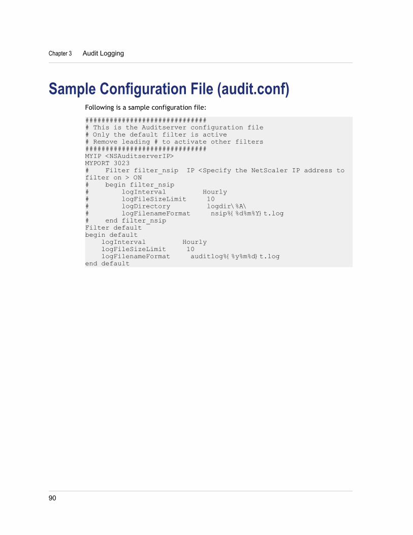
Sample Configuration File (audit.conf)Following is a sample configuration file:
############################### This is the Auditserver configuration file# Only the default filter is active# Remove leading # to activate other filters##############################MYIP <NSAuditserverIP>MYPORT 3023# Filter filter_nsip IP <Specify the NetScaler IP address to filter on > ON# begin filter_nsip# logInterval Hourly# logFileSizeLimit 10# logDirectory logdir\%A\# logFilenameFormat nsip%{%d%m%Y}t.log# end filter_nsipFilter default begin default logInterval Hourly logFileSizeLimit 10 logFilenameFormat auditlog%{%y%m%d}t.logend default
Chapter 3 Audit Logging
90
Chapter 4
Web Server Logging
Topics:• Configuring the NetScaler
Appliance for Web ServerLogging
• Installing and Configuringthe Client System for WebServer Logging
• Running the NSWL Client
• Customizing Logging on theNSWL Client System
• Sample Configuration File
• Arguments for Defining aCustom Log Format
• Time Format Definition
You can use the Web server logging feature to send logs ofHTTP and HTTPS requests to a client system for storage andretrieval. This feature has two components: the Web logserver, which runs on the Citrix® NetScaler® appliance, andthe NetScaler Web Logging (NSWL) client, which runs on theclient system. When you run the client, it connects to theNetScaler. The NetScaler buffers the HTTP and HTTPS requestlog entries before sending them to the NSWL client, and theclient can filter the entries before storing them. You can logHTTP and HTTPS requests for all of your Web servers on oneNSWL client system.
To configure Web server logging, you first enable the Weblogging feature on the NetScaler and configure the size of thebuffer for temporarily storing the log entries. Then, youinstall NSWL on the client system. You then add the NetScalerIP address (NSIP) to the NSWL configuration file. You are nowready to start the NSWL client to begin logging. You cancustomize Web server logging by making additionalmodifications to the NSWL configuration file (log.conf).
91
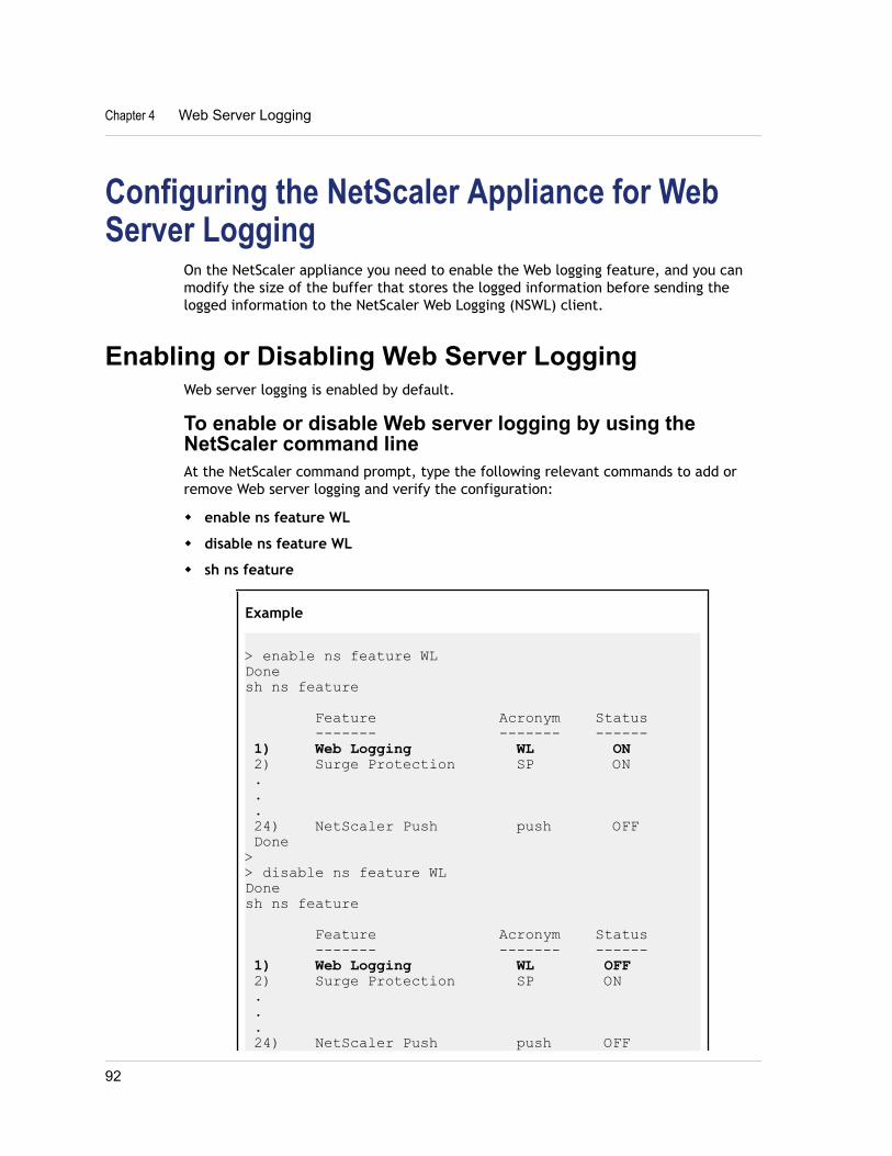
Configuring the NetScaler Appliance for WebServer Logging
On the NetScaler appliance you need to enable the Web logging feature, and you canmodify the size of the buffer that stores the logged information before sending thelogged information to the NetScaler Web Logging (NSWL) client.
Enabling or Disabling Web Server LoggingWeb server logging is enabled by default.
To enable or disable Web server logging by using theNetScaler command lineAt the NetScaler command prompt, type the following relevant commands to add orremove Web server logging and verify the configuration:
w enable ns feature WL
w disable ns feature WL
w sh ns feature
Example
> enable ns feature WLDonesh ns feature
Feature Acronym Status ------- ------- ------ 1) Web Logging WL ON 2) Surge Protection SP ON . . . 24) NetScaler Push push OFF Done>> disable ns feature WLDonesh ns feature
Feature Acronym Status ------- ------- ------ 1) Web Logging WL OFF 2) Surge Protection SP ON . . . 24) NetScaler Push push OFF
Chapter 4 Web Server Logging
92
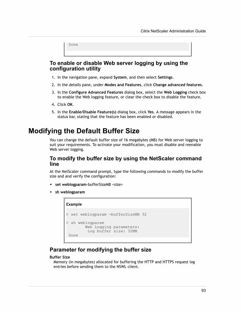
Done
To enable or disable Web server logging by using theconfiguration utility1. In the navigation pane, expand System, and then select Settings.
2. In the details pane, under Modes and Features, click Change advanced features.
3. In the Configure Advanced Features dialog box, select the Web Logging check boxto enable the Web logging feature, or clear the check box to disable the feature.
4. Click OK.
5. In the Enable/Disable Feature(s) dialog box, click Yes. A message appears in thestatus bar, stating that the feature has been enabled or disabled.
Modifying the Default Buffer SizeYou can change the default buffer size of 16 megabytes (MB) for Web server logging tosuit your requirements. To activate your modification, you must disable and reenableWeb server logging.
To modify the buffer size by using the NetScaler commandlineAt the NetScaler command prompt, type the following commands to modify the buffersize and and verify the configuration:
w set weblogparam-bufferSizeMB <size>
w sh weblogparam
Example > set weblogparam -bufferSizeMB 32
> sh weblogparam Web Logging parameters: Log buffer size: 32MB Done
Parameter for modifying the buffer sizeBuffer Size
Memory (in megabytes) allocated for buffering the HTTP and HTTPS request logentries before sending them to the NSWL client.
Citrix NetScaler Administration Guide
93
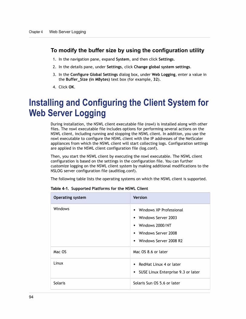
To modify the buffer size by using the configuration utility1. In the navigation pane, expand System, and then click Settings.
2. In the details pane, under Settings, click Change global system settings.
3. In the Configure Global Settings dialog box, under Web Logging, enter a value inthe Buffer_Size (in MBytes) text box (for example, 32).
4. Click OK.
Installing and Configuring the Client System forWeb Server Logging
During installation, the NSWL client executable file (nswl) is installed along with otherfiles. The nswl executable file includes options for performing several actions on theNSWL client, including running and stopping the NSWL client. In addition, you use thenswl executable to configure the NSWL client with the IP addresses of the NetScalerappliances from which the NSWL client will start collecting logs. Configuration settingsare applied in the NSWL client configuration file (log.conf).
Then, you start the NSWL client by executing the nswl executable. The NSWL clientconfiguration is based on the settings in the configuration file. You can furthercustomize logging on the NSWL client system by making additional modifications to theNSLOG server configuration file (auditlog.conf).
The following table lists the operating systems on which the NSWL client is supported.
Table 4-1. Supported Platforms for the NSWL Client
Operating system Version
Windows w Windows XP Professional
w Windows Server 2003
w Windows 2000/NT
w Windows Server 2008
w Windows Server 2008 R2
Mac OS Mac OS 8.6 or later
Linux w RedHat Linux 4 or later
w SUSE Linux Enterprise 9.3 or later
Solaris Solaris Sun OS 5.6 or later
Chapter 4 Web Server Logging
94
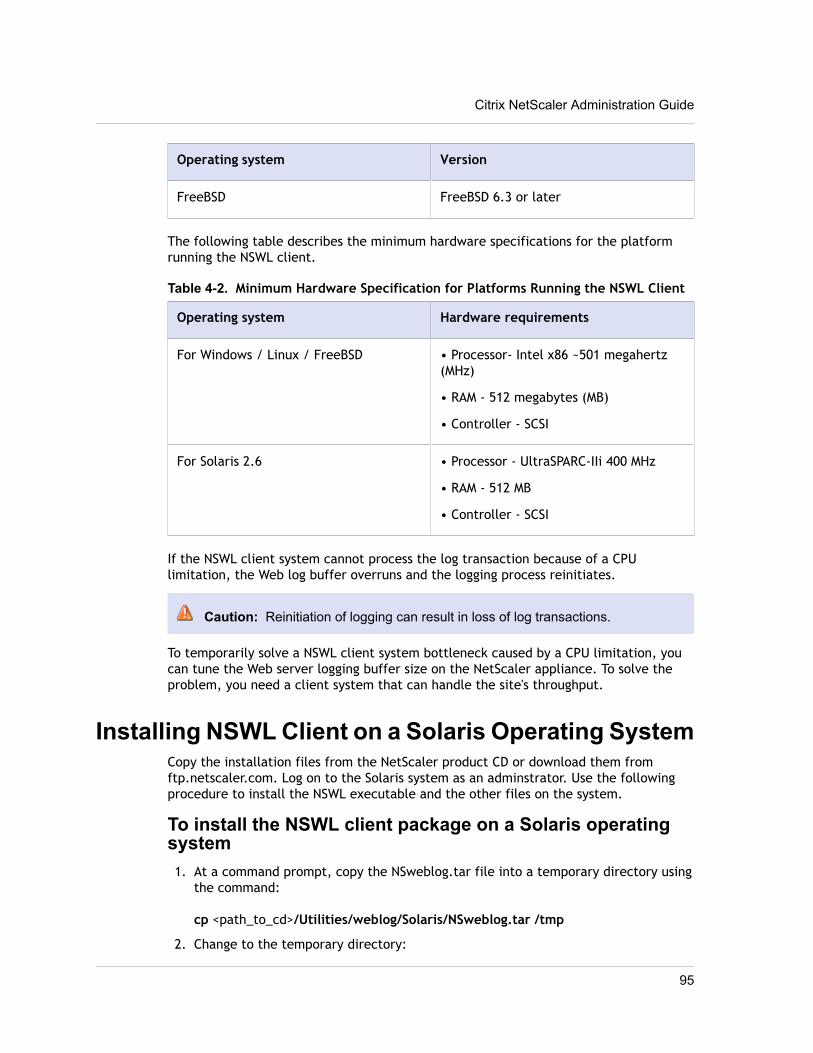
Operating system Version
FreeBSD FreeBSD 6.3 or later
The following table describes the minimum hardware specifications for the platformrunning the NSWL client.
Table 4-2. Minimum Hardware Specification for Platforms Running the NSWL Client
Operating system Hardware requirements
For Windows / Linux / FreeBSD • Processor- Intel x86 ~501 megahertz(MHz)
• RAM - 512 megabytes (MB)
• Controller - SCSI
For Solaris 2.6 • Processor - UltraSPARC-IIi 400 MHz
• RAM - 512 MB
• Controller - SCSI
If the NSWL client system cannot process the log transaction because of a CPUlimitation, the Web log buffer overruns and the logging process reinitiates.
Caution: Reinitiation of logging can result in loss of log transactions.
To temporarily solve a NSWL client system bottleneck caused by a CPU limitation, youcan tune the Web server logging buffer size on the NetScaler appliance. To solve theproblem, you need a client system that can handle the site's throughput.
Installing NSWL Client on a Solaris Operating SystemCopy the installation files from the NetScaler product CD or download them fromftp.netscaler.com. Log on to the Solaris system as an adminstrator. Use the followingprocedure to install the NSWL executable and the other files on the system.
To install the NSWL client package on a Solaris operatingsystem1. At a command prompt, copy the NSweblog.tar file into a temporary directory using
the command:
cp <path_to_cd>/Utilities/weblog/Solaris/NSweblog.tar /tmp
2. Change to the temporary directory:
Citrix NetScaler Administration Guide
95
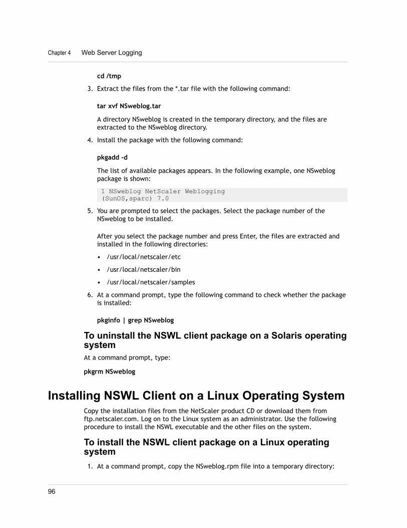
cd /tmp
3. Extract the files from the *.tar file with the following command:
tar xvf NSweblog.tar
A directory NSweblog is created in the temporary directory, and the files areextracted to the NSweblog directory.
4. Install the package with the following command:
pkgadd -d
The list of available packages appears. In the following example, one NSweblogpackage is shown:
1 NSweblog NetScaler Weblogging (SunOS,sparc) 7.0
5. You are prompted to select the packages. Select the package number of theNSweblog to be installed.
After you select the package number and press Enter, the files are extracted andinstalled in the following directories:
• /usr/local/netscaler/etc
• /usr/local/netscaler/bin
• /usr/local/netscaler/samples
6. At a command prompt, type the following command to check whether the packageis installed:
pkginfo | grep NSweblog
To uninstall the NSWL client package on a Solaris operatingsystemAt a command prompt, type:
pkgrm NSweblog
Installing NSWL Client on a Linux Operating SystemCopy the installation files from the NetScaler product CD or download them fromftp.netscaler.com. Log on to the Linux system as an administrator. Use the followingprocedure to install the NSWL executable and the other files on the system.
To install the NSWL client package on a Linux operatingsystem1. At a command prompt, copy the NSweblog.rpm file into a temporary directory:
Chapter 4 Web Server Logging
96
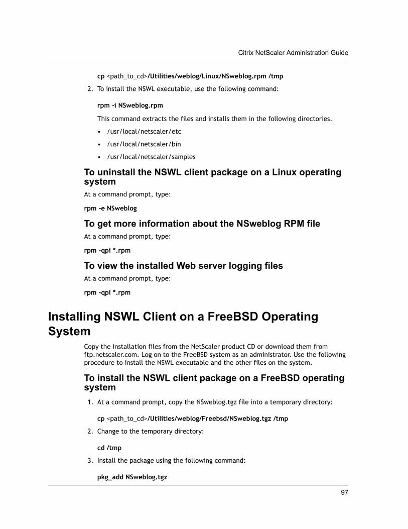
cp <path_to_cd>/Utilities/weblog/Linux/NSweblog.rpm /tmp
2. To install the NSWL executable, use the following command:
rpm -i NSweblog.rpm
This command extracts the files and installs them in the following directories.
• /usr/local/netscaler/etc
• /usr/local/netscaler/bin
• /usr/local/netscaler/samples
To uninstall the NSWL client package on a Linux operatingsystemAt a command prompt, type:
rpm -e NSweblog
To get more information about the NSweblog RPM fileAt a command prompt, type:
rpm -qpi *.rpm
To view the installed Web server logging filesAt a command prompt, type:
rpm -qpl *.rpm
Installing NSWL Client on a FreeBSD OperatingSystem
Copy the installation files from the NetScaler product CD or download them fromftp.netscaler.com. Log on to the FreeBSD system as an administrator. Use the followingprocedure to install the NSWL executable and the other files on the system.
To install the NSWL client package on a FreeBSD operatingsystem1. At a command prompt, copy the NSweblog.tgz file into a temporary directory:
cp <path_to_cd>/Utilities/weblog/Freebsd/NSweblog.tgz /tmp
2. Change to the temporary directory:
cd /tmp
3. Install the package using the following command:
pkg_add NSweblog.tgz
Citrix NetScaler Administration Guide
97
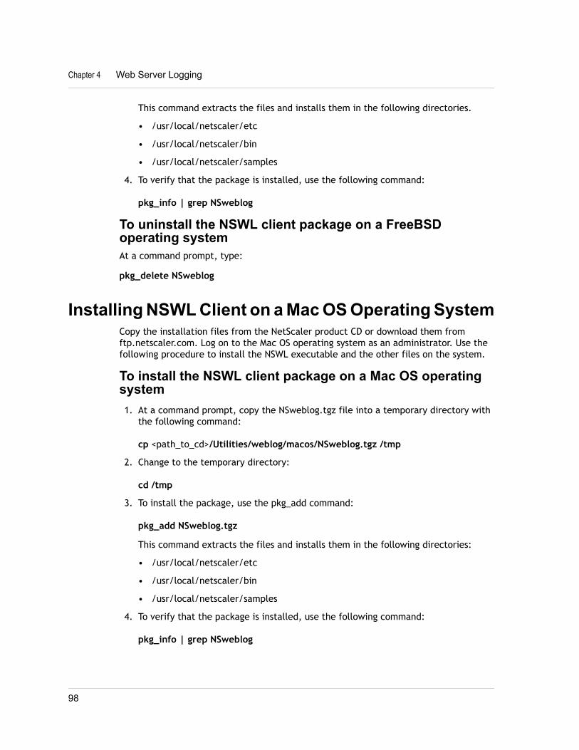
This command extracts the files and installs them in the following directories.
• /usr/local/netscaler/etc
• /usr/local/netscaler/bin
• /usr/local/netscaler/samples
4. To verify that the package is installed, use the following command:
pkg_info | grep NSweblog
To uninstall the NSWL client package on a FreeBSDoperating systemAt a command prompt, type:
pkg_delete NSweblog
Installing NSWL Client on a Mac OS Operating SystemCopy the installation files from the NetScaler product CD or download them fromftp.netscaler.com. Log on to the Mac OS operating system as an administrator. Use thefollowing procedure to install the NSWL executable and the other files on the system.
To install the NSWL client package on a Mac OS operatingsystem1. At a command prompt, copy the NSweblog.tgz file into a temporary directory with
the following command:
cp <path_to_cd>/Utilities/weblog/macos/NSweblog.tgz /tmp
2. Change to the temporary directory:
cd /tmp
3. To install the package, use the pkg_add command:
pkg_add NSweblog.tgz
This command extracts the files and installs them in the following directories:
• /usr/local/netscaler/etc
• /usr/local/netscaler/bin
• /usr/local/netscaler/samples
4. To verify that the package is installed, use the following command:
pkg_info | grep NSweblog
Chapter 4 Web Server Logging
98
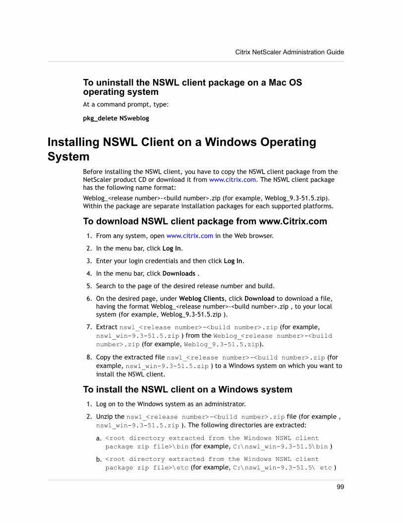
To uninstall the NSWL client package on a Mac OSoperating systemAt a command prompt, type:
pkg_delete NSweblog
Installing NSWL Client on a Windows OperatingSystem
Before installing the NSWL client, you have to copy the NSWL client package from theNetScaler product CD or download it from www.citrix.com. The NSWL client packagehas the following name format:
Weblog_<release number>-<build number>.zip (for example, Weblog_9.3-51.5.zip).Within the package are separate installation packages for each supported platforms.
To download NSWL client package from www.Citrix.com1. From any system, open www.citrix.com in the Web browser.
2. In the menu bar, click Log In.
3. Enter your login credentials and then click Log In.
4. In the menu bar, click Downloads .
5. Search to the page of the desired release number and build.
6. On the desired page, under Weblog Clients, click Download to download a file,having the format Weblog_<release number>-<build number>.zip , to your localsystem (for example, Weblog_9.3-51.5.zip ).
7. Extract nswl_<release number>-<build number>.zip (for example,nswl_win-9.3-51.5.zip ) from the Weblog_<release number>-<buildnumber>.zip (for example, Weblog_9.3-51.5.zip).
8. Copy the extracted file nswl_<release number>-<build number>.zip (forexample, nswl_win-9.3-51.5.zip ) to a Windows system on which you want toinstall the NSWL client.
To install the NSWL client on a Windows system1. Log on to the Windows system as an administrator.
2. Unzip the nswl_<release number>-<build number>.zip file (for example ,nswl_win-9.3-51.5.zip ). The following directories are extracted:
a. <root directory extracted from the Windows NSWL clientpackage zip file>\bin (for example, C:\nswl_win-9.3-51.5\bin )
b. <root directory extracted from the Windows NSWL clientpackage zip file>\etc (for example, C:\nswl_win-9.3-51.5\ etc )
Citrix NetScaler Administration Guide
99
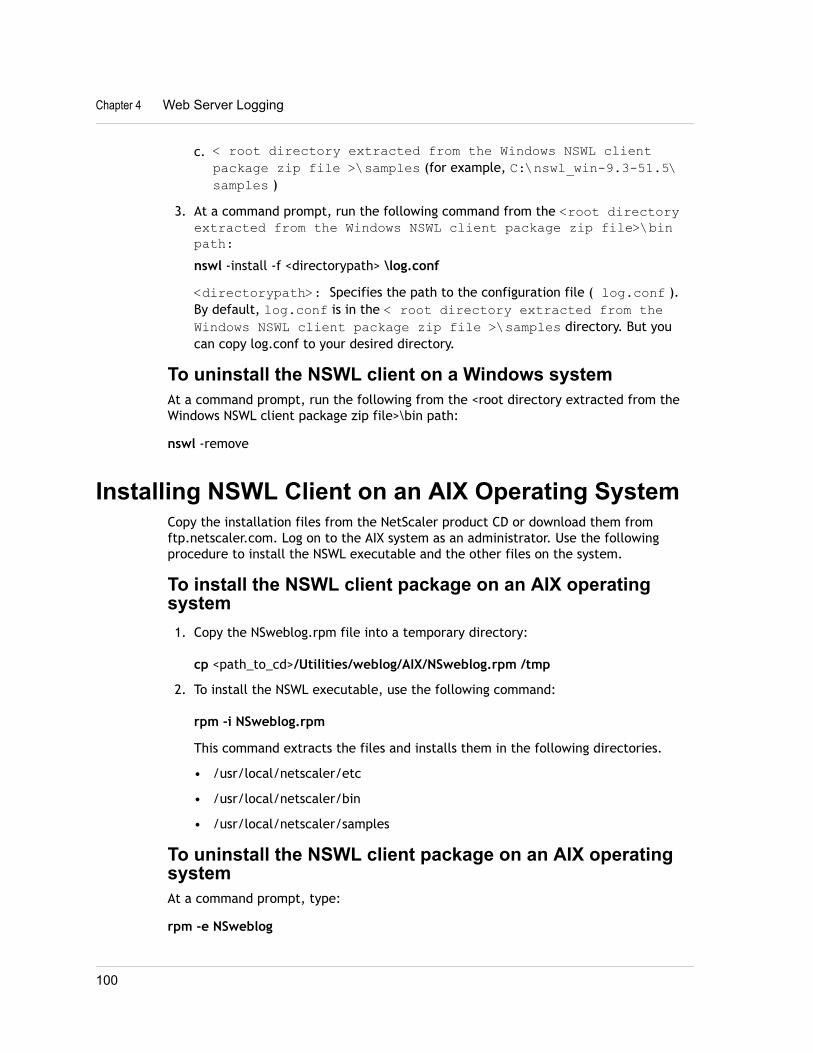
c. < root directory extracted from the Windows NSWL clientpackage zip file >\samples (for example, C:\nswl_win-9.3-51.5\samples )
3. At a command prompt, run the following command from the <root directoryextracted from the Windows NSWL client package zip file>\binpath:nswl -install -f <directorypath> \log.conf
<directorypath>: Specifies the path to the configuration file ( log.conf ).By default, log.conf is in the < root directory extracted from theWindows NSWL client package zip file >\samples directory. But youcan copy log.conf to your desired directory.
To uninstall the NSWL client on a Windows systemAt a command prompt, run the following from the <root directory extracted from theWindows NSWL client package zip file>\bin path:
nswl -remove
Installing NSWL Client on an AIX Operating SystemCopy the installation files from the NetScaler product CD or download them fromftp.netscaler.com. Log on to the AIX system as an administrator. Use the followingprocedure to install the NSWL executable and the other files on the system.
To install the NSWL client package on an AIX operatingsystem1. Copy the NSweblog.rpm file into a temporary directory:
cp <path_to_cd>/Utilities/weblog/AIX/NSweblog.rpm /tmp
2. To install the NSWL executable, use the following command:
rpm -i NSweblog.rpm
This command extracts the files and installs them in the following directories.
• /usr/local/netscaler/etc
• /usr/local/netscaler/bin
• /usr/local/netscaler/samples
To uninstall the NSWL client package on an AIX operatingsystemAt a command prompt, type:
rpm -e NSweblog
Chapter 4 Web Server Logging
100
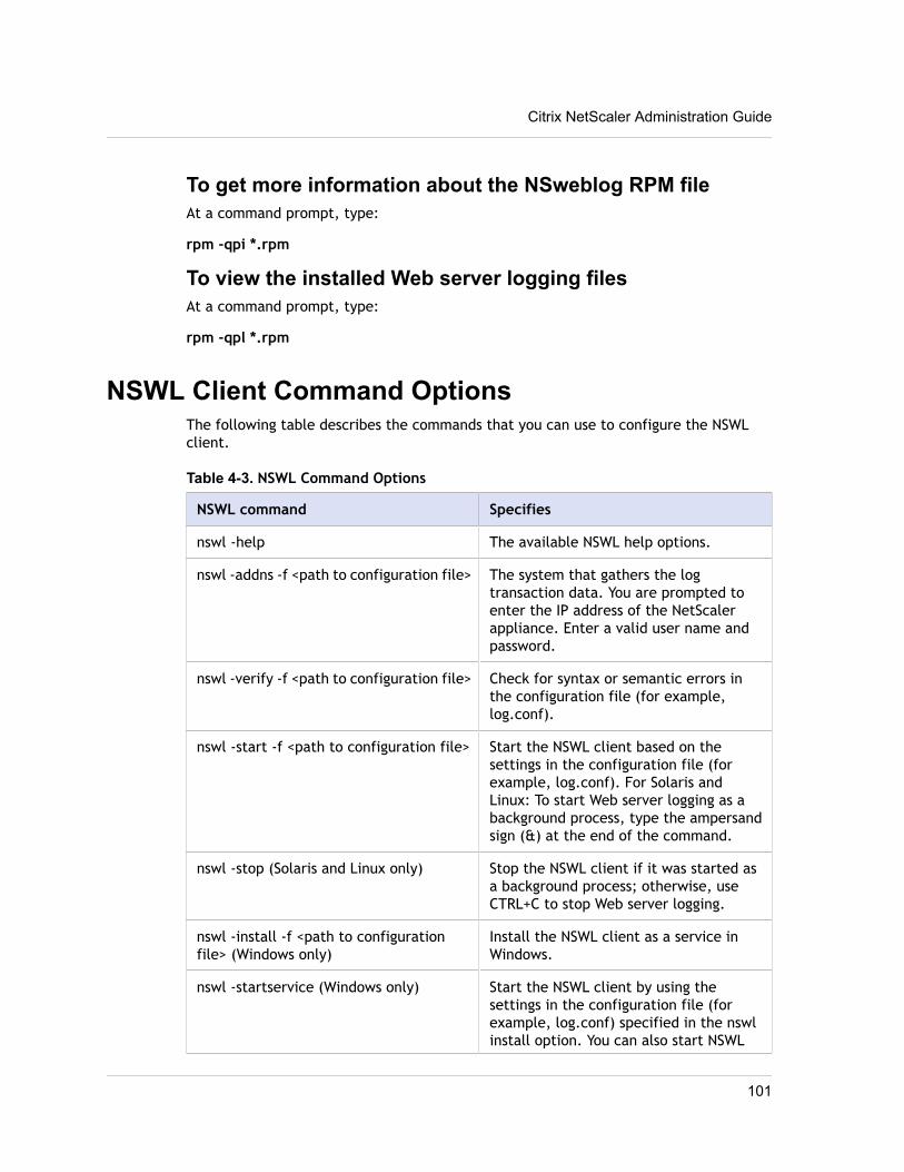
To get more information about the NSweblog RPM fileAt a command prompt, type:
rpm -qpi *.rpm
To view the installed Web server logging filesAt a command prompt, type:
rpm -qpl *.rpm
NSWL Client Command OptionsThe following table describes the commands that you can use to configure the NSWLclient.
Table 4-3. NSWL Command Options
NSWL command Specifies
nswl -help The available NSWL help options.
nswl -addns -f <path to configuration file> The system that gathers the logtransaction data. You are prompted toenter the IP address of the NetScalerappliance. Enter a valid user name andpassword.
nswl -verify -f <path to configuration file> Check for syntax or semantic errors inthe configuration file (for example,log.conf).
nswl -start -f <path to configuration file> Start the NSWL client based on thesettings in the configuration file (forexample, log.conf). For Solaris andLinux: To start Web server logging as abackground process, type the ampersandsign (&) at the end of the command.
nswl -stop (Solaris and Linux only) Stop the NSWL client if it was started asa background process; otherwise, useCTRL+C to stop Web server logging.
nswl -install -f <path to configurationfile> (Windows only)
Install the NSWL client as a service inWindows.
nswl -startservice (Windows only) Start the NSWL client by using thesettings in the configuration file (forexample, log.conf) specified in the nswlinstall option. You can also start NSWL
Citrix NetScaler Administration Guide
101
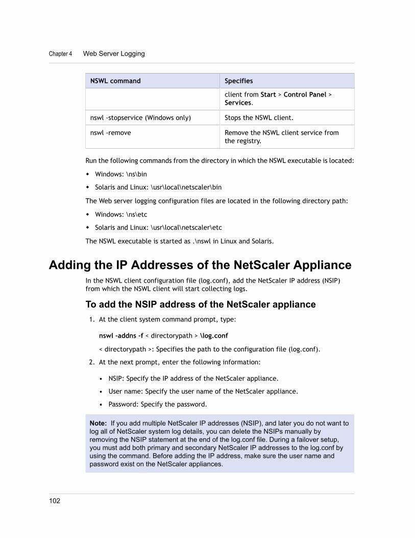
NSWL command Specifies
client from Start > Control Panel >Services.
nswl -stopservice (Windows only) Stops the NSWL client.
nswl -remove Remove the NSWL client service fromthe registry.
Run the following commands from the directory in which the NSWL executable is located:
w Windows: \ns\bin
w Solaris and Linux: \usr\local\netscaler\bin
The Web server logging configuration files are located in the following directory path:
w Windows: \ns\etc
w Solaris and Linux: \usr\local\netscaler\etc
The NSWL executable is started as .\nswl in Linux and Solaris.
Adding the IP Addresses of the NetScaler ApplianceIn the NSWL client configuration file (log.conf), add the NetScaler IP address (NSIP)from which the NSWL client will start collecting logs.
To add the NSIP address of the NetScaler appliance1. At the client system command prompt, type:
nswl -addns -f < directorypath > \log.conf
< directorypath >: Specifies the path to the configuration file (log.conf).
2. At the next prompt, enter the following information:
• NSIP: Specify the IP address of the NetScaler appliance.
• User name: Specify the user name of the NetScaler appliance.
• Password: Specify the password.
Note: If you add multiple NetScaler IP addresses (NSIP), and later you do not want tolog all of NetScaler system log details, you can delete the NSIPs manually byremoving the NSIP statement at the end of the log.conf file. During a failover setup,you must add both primary and secondary NetScaler IP addresses to the log.conf byusing the command. Before adding the IP address, make sure the user name andpassword exist on the NetScaler appliances.
Chapter 4 Web Server Logging
102
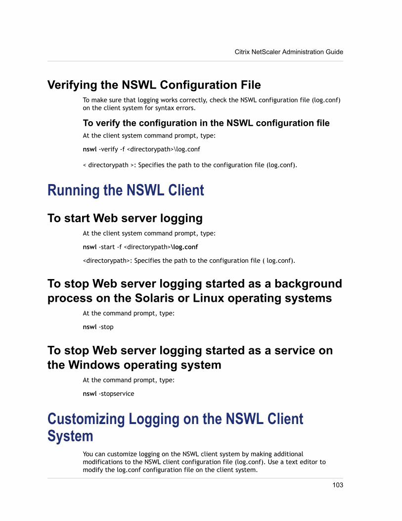
Verifying the NSWL Configuration FileTo make sure that logging works correctly, check the NSWL configuration file (log.conf)on the client system for syntax errors.
To verify the configuration in the NSWL configuration fileAt the client system command prompt, type:
nswl -verify -f <directorypath>\log.conf
< directorypath >: Specifies the path to the configuration file (log.conf).
Running the NSWL ClientTo start Web server logging
At the client system command prompt, type:
nswl -start -f <directorypath>\log.conf
<directorypath>: Specifies the path to the configuration file ( log.conf).
To stop Web server logging started as a backgroundprocess on the Solaris or Linux operating systems
At the command prompt, type:
nswl -stop
To stop Web server logging started as a service onthe Windows operating system
At the command prompt, type:
nswl -stopservice
Customizing Logging on the NSWL ClientSystem
You can customize logging on the NSWL client system by making additionalmodifications to the NSWL client configuration file (log.conf). Use a text editor tomodify the log.conf configuration file on the client system.
Citrix NetScaler Administration Guide
103
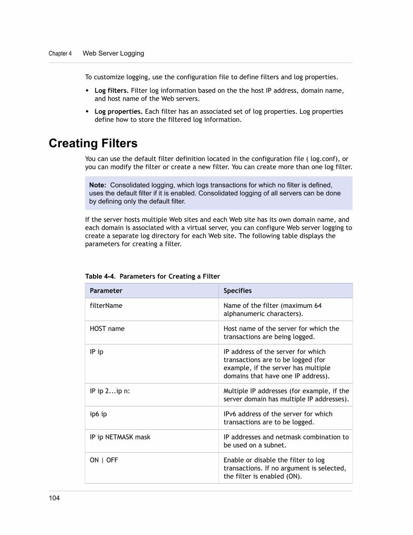
To customize logging, use the configuration file to define filters and log properties.
w Log filters. Filter log information based on the the host IP address, domain name,and host name of the Web servers.
w Log properties. Each filter has an associated set of log properties. Log propertiesdefine how to store the filtered log information.
Creating FiltersYou can use the default filter definition located in the configuration file ( log.conf), oryou can modify the filter or create a new filter. You can create more than one log filter.
Note: Consolidated logging, which logs transactions for which no filter is defined,uses the default filter if it is enabled. Consolidated logging of all servers can be doneby defining only the default filter.
If the server hosts multiple Web sites and each Web site has its own domain name, andeach domain is associated with a virtual server, you can configure Web server logging tocreate a separate log directory for each Web site. The following table displays theparameters for creating a filter.
Table 4-4. Parameters for Creating a Filter
Parameter Specifies
filterName Name of the filter (maximum 64alphanumeric characters).
HOST name Host name of the server for which thetransactions are being logged.
IP ip IP address of the server for whichtransactions are to be logged (forexample, if the server has multipledomains that have one IP address).
IP ip 2...ip n: Multiple IP addresses (for example, if theserver domain has multiple IP addresses).
ip6 ip IPv6 address of the server for whichtransactions are to be logged.
IP ip NETMASK mask IP addresses and netmask combination tobe used on a subnet.
ON | OFF Enable or disable the filter to logtransactions. If no argument is selected,the filter is enabled (ON).
Chapter 4 Web Server Logging
104
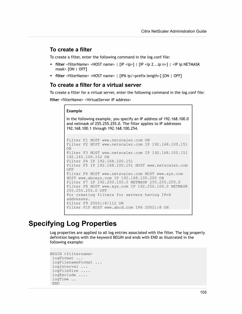
To create a filterTo create a filter, enter the following command in the log.conf file:
w filter <filterName> <HOST name> | [IP <ip>] | [IP <ip 2...ip n>] | <IP ip NETMASKmask> [ON | OFF]
w filter <filterName> <HOST name> | [IP6 ip/<prefix length>] [ON | OFF]
To create a filter for a virtual serverTo create a filter for a virtual server, enter the following command in the log.conf file:
filter <filterName> <VirtualServer IP address>
Example
In the following example, you specify an IP address of 192.168.100.0and netmask of 255.255.255.0. The filter applies to IP addresses192.168.100.1 through 192.168.100.254.
Filter F1 HOST www.netscaler.com ONFilter F2 HOST www.netscaler.com IP 192.168.100.151 ONFilter F3 HOST www.netscaler.com IP 192.168.100.151 192.165.100.152 ONFilter F4 IP 192.168.100.151Filter F5 IP 192.168.100.151 HOST www.netscaler.com OFFFilter F6 HOST www.netscaler.com HOST www.xyz.com HOST www.abcxyz.com IP 192.168.100.200 ONFilter F7 IP 192.250.100.0 NETMASK 255.255.255.0Filter F8 HOST www.xyz.com IP 192.250.100.0 NETMASK 255.255.255.0 OFFFor creating filters for servers having IPv6 addresses.Filter F9 2002::8/112 ONFilter F10 HOST www.abcd.com IP6 2002::8 ON
Specifying Log PropertiesLog properties are applied to all log entries associated with the filter. The log propertydefinition begins with the keyword BEGIN and ends with END as illustrated in thefollowing example:
BEGIN <filtername> logFormat ... logFilenameFormat ... logInterval ... logFileSize .... logExclude .... logTime …. END
Citrix NetScaler Administration Guide
105
Entries in the definition can include the following:
w LogFormat specifies the Web server logging feature that supports NCSA, W3CExtended, and custom log file formats.
By default, the logformat property is w3c. To override, enter custom or NCSA in theconfiguration file, for example:
LogFormat NCSA
Note: For the NCSA and custom log formats, local time is used to time stamptransactions and for file rotation.
w LogInterval specifies the intervals at which new log files are created. Use one ofthe following values:
• Hourly: A file is created every hour.
• Daily: A file is created every day at midnight. Default value.
• Weekly: A file is created every Sunday at midnight.
• Monthly: A file is created on the first day of the month at midnight.
• None: A file is created only once, when Web server logging starts.
Example
LogInterval Dailyw LogFileSizeLimit specifies the maximum size of the log file in MB. It can be used
with any log interval (weekly, monthly, and so on.) A file is created when themaximum file size limit is reached or when the defined log interval time elapses.
To override this behavior, specify the size as the loginterval property so that a file iscreated only when the log file size limit is reached.
The default LogFileSizeLimit is 10 MB.
Example
LogFileSizeLimit 35w LogFilenameFormat specifies the file name format of the log file. The name of the
file can be of the following types:
• Static: Specifies a constant string that contains the absolute path and file name.
• Dynamic: Specifies an expression containing the following format:
w Server IP address (%A)
w Date (%{format}t)
w URL suffix (%x)
w Host name (%v)
Chapter 4 Web Server Logging
106
Example
LogFileNameFormat Ex%{%m%d%y}t.logThis command creates the first file name as Exmmddyy.log, then every hour createsa file with file name: Exmmddyy.log.0, Exmmddyy.log.1,..., Exmmddyy.log.n.
Example
LogInterval size LogFileSize 100 LogFileNameFormat Ex%{%m%d%y}t
Caution: The date format %t specified in the LogFilenameFormat commandoverrides the log interval property for that filter. To prevent a new file being createdevery day instead of when the specified log file size is reached, do not use %t inthe LogFilenameFormat.
w LogExclude prevents logging of transactions with the specified file extensions.
Example
LogExclude .htmlThis command creates a log file that excludes log transactions for *.html files.
w LogTime specifies log time as either GMT or LOCAL.
The defaults are:
• NCSA log file format: LOCAL
• W3C log file format: GMT.
Understanding the NCSA and W3C Log FormatsThe NetScaler supports the following standard log file formats:
w NCSA Common Log Format
w W3C Extended Log Format
NCSA Common Log FormatIf the log file format is NCSA, the log file displays log information in the following format:
Client_IP_address -User_Name [Date:Time -TimeZone] "Method Object HTTP_version" HTTP_StatusCode BytesSentTo use the NCSA Common log format, enter NCSA in the LogFormat argument in thelog.conf file.
The following table describes the NCSA Common log format.
Citrix NetScaler Administration Guide
107
Table 4-5. NCSA Common Log Format
Argument Specifies
Client _IP_address The IP address of the client computer.
User Name The user name.
Date The date of the transaction.
Time The time when the transaction wascompleted.
Time Zone The time zone (Greenwich Mean Time orlocal time).
Method The request method (for example; GET,POST).
Object The URL.
HTTP_version The version of HTTP used by the client.
HTTP_StatusCode The status code in the response.
Bytes Sent The number of bytes sent from the server.
W3C Extended Log FormatAn extended log file contains a sequence of lines containing ASCII charactersterminated by either a Line Feed (LF) or the sequence Carriage Return Line Feed(CRLF.) Log file generators must follow the line termination convention for the platformon which they are run.
Log analyzers must accept either LF or CRLF form. Each line may contain either adirective or an entry. If you want to use the W3C Extended log format, enter W3C asthe Log-Format argument in the log.conf file.
By default, the standard W3C log format is defined internally as the custom log format,shown as follows:
%{%Y-%m-%d%H:%M:%S}t %a %u %S %A %p %m %U %q %s %j %J %T %H %+{user-agent}i %+{cookie} i%+{referer}iFor a description of the meaning of this each custom format, see Arguments forDefining a Custom Log Format on page 116. You can also change the order or removesome fields in this W3C log format. For example:
logFormat W3C %{%Y-%m-%d%H:%M:%S}t %m %UW3C log entries are created with the following format:
#Version: 1.0 #Fields: date time cs-method cs-uri #Date: 12-Jun-2001 12:34
Chapter 4 Web Server Logging
108
2001-06-12 12:34:23 GET /sports/football.html 2001-06-12 12:34:30 GET /sports/football.html
EntriesEntries consist of a sequence of fields relating to a single HTTP transaction. Fields areseparated by white space; Citrix recommends the use of tab characters. If a field in aparticular entry is not used, a dash (-) marks the omitted field.
DirectivesDirectives record information about the logging process. Lines beginning with thepound sign (#) contain directives.
The following table describes the directives.
Table 4-6. Directive Descriptions
Directive Description
Version: <integer>.<integer> Displays the version of the extended logfile format used. This document definesversion 1.0.
Fields: [<specifier>...] Identifies the fields recorded in the log.
Software: <string> Identifies the software that generatedthe log.
Start-Date: <date> <time> Displays the date and time at which thelog was started.
End-Date: <date> <time> Displays the date and time at whichlogging finished.
Date: <date> <time> Displays the date and time when theentry was added.
Remark: <text> Displays comments. Analysis tools ignoredata recorded in this field.
Note: The Version and Fields directives are required. They precede all other entries inthe log file.
Example
The following sample log file shows the log entries in W3C Extended log format:
#Version: 1.0 #Fields: time cs-method cs-uri #Date: 12-Jan-1996 00:00:00 00:34:23 GET /sports/football.html 12:21:16 GET /sports/football.html
Citrix NetScaler Administration Guide
109
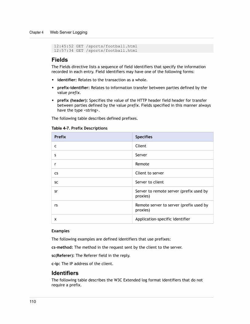
12:45:52 GET /sports/football.html 12:57:34 GET /sports/football.html
FieldsThe Fields directive lists a sequence of field identifiers that specify the informationrecorded in each entry. Field identifiers may have one of the following forms:
w identifier: Relates to the transaction as a whole.
w prefix-identifier: Relates to information transfer between parties defined by thevalue prefix.
w prefix (header): Specifies the value of the HTTP header field header for transferbetween parties defined by the value prefix. Fields specified in this manner alwayshave the type <string>.
The following table describes defined prefixes.
Table 4-7. Prefix Descriptions
Prefix Specifies
c Client
s Server
r Remote
cs Client to server
sc Server to client
sr Server to remote server (prefix used byproxies)
rs Remote server to server (prefix used byproxies)
x Application-specific identifier
Examples
The following examples are defined identifiers that use prefixes:
cs-method: The method in the request sent by the client to the server.
sc(Referer): The Referer field in the reply.
c-ip: The IP address of the client.
IdentifiersThe following table describes the W3C Extended log format identifiers that do notrequire a prefix.
Chapter 4 Web Server Logging
110
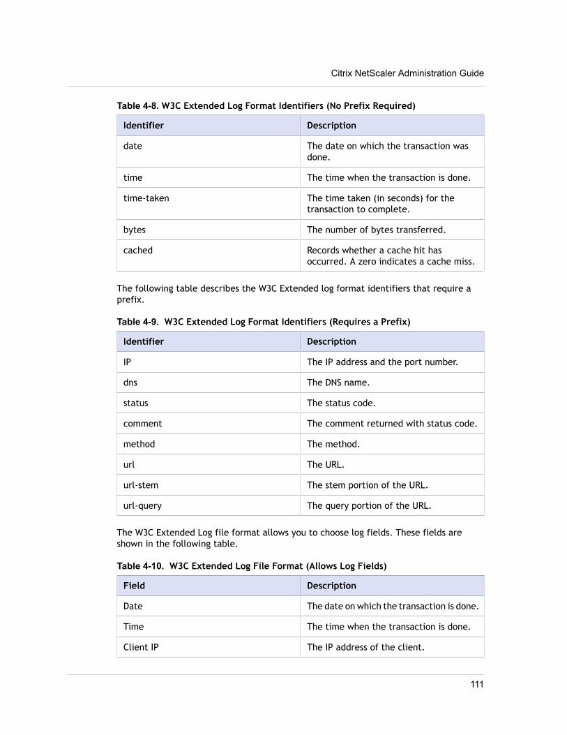
Table 4-8. W3C Extended Log Format Identifiers (No Prefix Required)
Identifier Description
date The date on which the transaction wasdone.
time The time when the transaction is done.
time-taken The time taken (in seconds) for thetransaction to complete.
bytes The number of bytes transferred.
cached Records whether a cache hit hasoccurred. A zero indicates a cache miss.
The following table describes the W3C Extended log format identifiers that require aprefix.
Table 4-9. W3C Extended Log Format Identifiers (Requires a Prefix)
Identifier Description
IP The IP address and the port number.
dns The DNS name.
status The status code.
comment The comment returned with status code.
method The method.
url The URL.
url-stem The stem portion of the URL.
url-query The query portion of the URL.
The W3C Extended Log file format allows you to choose log fields. These fields areshown in the following table.
Table 4-10. W3C Extended Log File Format (Allows Log Fields)
Field Description
Date The date on which the transaction is done.
Time The time when the transaction is done.
Client IP The IP address of the client.
Citrix NetScaler Administration Guide
111
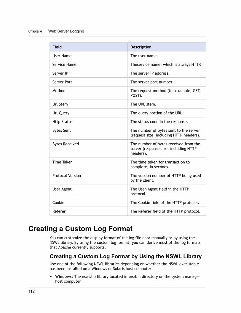
Field Description
User Name The user name.
Service Name Theservice name, which is always HTTP.
Server IP The server IP address.
Server Port The server port number
Method The request method (for example; GET,POST).
Url Stem The URL stem.
Url Query The query portion of the URL.
Http Status The status code in the response.
Bytes Sent The number of bytes sent to the server(request size, including HTTP headers).
Bytes Received The number of bytes received from theserver (response size, including HTTPheaders).
Time Taken The time taken for transaction tocomplete, in seconds.
Protocol Version The version number of HTTP being usedby the client.
User Agent The User-Agent field in the HTTPprotocol.
Cookie The Cookie field of the HTTP protocol.
Referer The Referer field of the HTTP protocol.
Creating a Custom Log FormatYou can customize the display format of the log file data manually or by using theNSWL library. By using the custom log format, you can derive most of the log formatsthat Apache currently supports.
Creating a Custom Log Format by Using the NSWL LibraryUse one of the following NSWL libraries depending on whether the NSWL executablehas been installed on a Windows or Solaris host computer:
w Windows: The nswl.lib library located in \ns\bin directory on the system managerhost computer.
Chapter 4 Web Server Logging
112
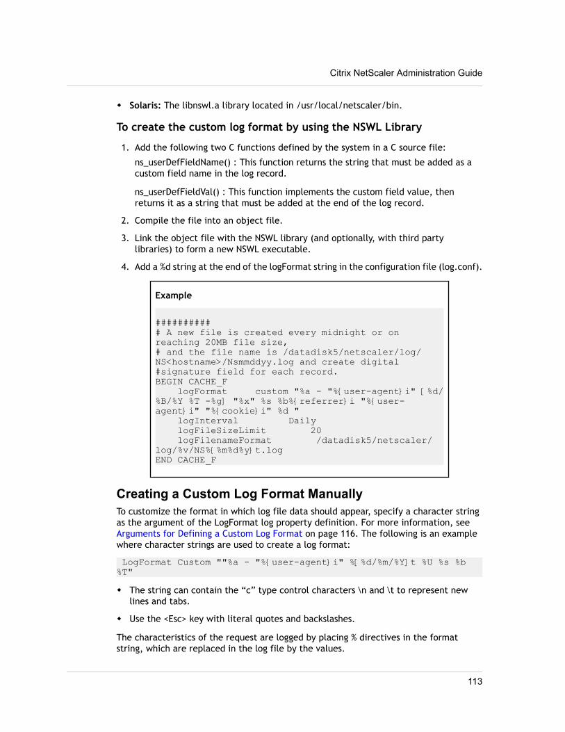
w Solaris: The libnswl.a library located in /usr/local/netscaler/bin.
To create the custom log format by using the NSWL Library
1. Add the following two C functions defined by the system in a C source file:
ns_userDefFieldName() : This function returns the string that must be added as acustom field name in the log record.
ns_userDefFieldVal() : This function implements the custom field value, thenreturns it as a string that must be added at the end of the log record.
2. Compile the file into an object file.
3. Link the object file with the NSWL library (and optionally, with third partylibraries) to form a new NSWL executable.
4. Add a %d string at the end of the logFormat string in the configuration file (log.conf).
Example
########### A new file is created every midnight or on reaching 20MB file size,# and the file name is /datadisk5/netscaler/log/NS<hostname>/Nsmmddyy.log and create digital#signature field for each record.BEGIN CACHE_F logFormat custom "%a - "%{user-agent}i" [%d/%B/%Y %T -%g] "%x" %s %b%{referrer}i "%{user-agent}i" "%{cookie}i" %d " logInterval Daily logFileSizeLimit 20 logFilenameFormat /datadisk5/netscaler/log/%v/NS%{%m%d%y}t.logEND CACHE_F
Creating a Custom Log Format ManuallyTo customize the format in which log file data should appear, specify a character stringas the argument of the LogFormat log property definition. For more information, see Arguments for Defining a Custom Log Format on page 116. The following is an examplewhere character strings are used to create a log format:
LogFormat Custom ""%a - "%{user-agent}i" %[%d/%m/%Y]t %U %s %b %T"w The string can contain the “c” type control characters \n and \t to represent new
lines and tabs.
w Use the <Esc> key with literal quotes and backslashes.
The characteristics of the request are logged by placing % directives in the formatstring, which are replaced in the log file by the values.
Citrix NetScaler Administration Guide
113
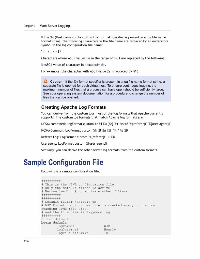
If the %v (Host name) or %x (URL suffix) format specifier is present in a log file nameformat string, the following characters in the file name are replaced by an underscoresymbol in the log configuration file name:
" * . / : < > ? \ |
Characters whose ASCII values lie in the range of 0-31 are replaced by the following:
%<ASCII value of character in hexadecimal>.
For example, the character with ASCII value 22 is replaced by %16.
Caution: If the %v format specifier is present in a log file name format string, aseparate file is opened for each virtual host. To ensure continuous logging, themaximum number of files that a process can have open should be sufficiently large.See your operating system documentation for a procedure to change the number offiles that can be opened.
Creating Apache Log FormatsYou can derive from the custom logs most of the log formats that Apache currentlysupports. The custom log formats that match Apache log formats are:
NCSA/combined: LogFormat custom %h %l %u [%t] "%r" %s %B "%{referer}i" "%{user-agent}i"
NCSA/Common: LogFormat custom %h %l %u [%t] "%r" %s %B
Referer Log: LogFormat custom "%{referer}i" -> %U
Useragent: LogFormat custom %{user-agent}i
Similarly, you can derive the other server log formats from the custom formats.
Sample Configuration FileFollowing is a sample configuration file:
########### This is the NSWL configuration file# Only the default filter is active# Remove leading # to activate other filters##################### Default filter (default on)# W3C Format logging, new file is created every hour or on reaching 10MB file size,# and the file name is Exyymmdd.log##########Filter defaultbegin default logFormat W3C logInterval Hourly logFileSizeLimit 10
Chapter 4 Web Server Logging
114
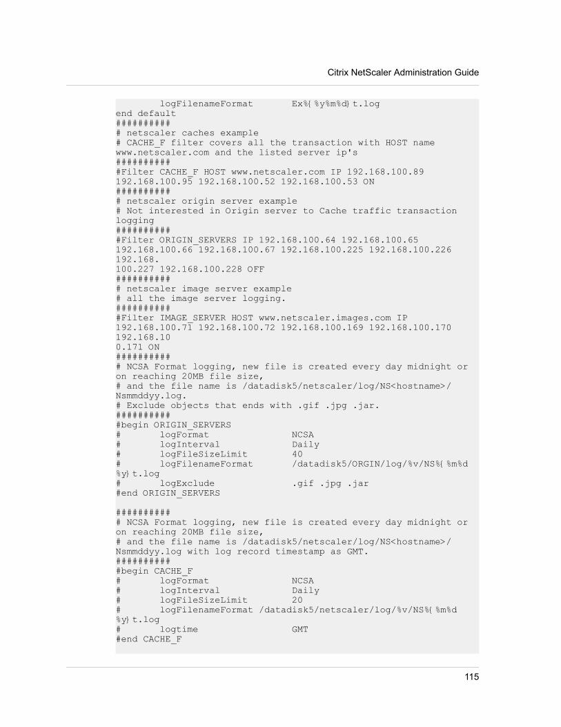
logFilenameFormat Ex%{%y%m%d}t.logend default########### netscaler caches example# CACHE_F filter covers all the transaction with HOST name www.netscaler.com and the listed server ip's###########Filter CACHE_F HOST www.netscaler.com IP 192.168.100.89 192.168.100.95 192.168.100.52 192.168.100.53 ON########### netscaler origin server example# Not interested in Origin server to Cache traffic transaction logging###########Filter ORIGIN_SERVERS IP 192.168.100.64 192.168.100.65 192.168.100.66 192.168.100.67 192.168.100.225 192.168.100.226 192.168.100.227 192.168.100.228 OFF########### netscaler image server example# all the image server logging.###########Filter IMAGE_SERVER HOST www.netscaler.images.com IP 192.168.100.71 192.168.100.72 192.168.100.169 192.168.100.170 192.168.100.171 ON########### NCSA Format logging, new file is created every day midnight or on reaching 20MB file size,# and the file name is /datadisk5/netscaler/log/NS<hostname>/Nsmmddyy.log.# Exclude objects that ends with .gif .jpg .jar.###########begin ORIGIN_SERVERS# logFormat NCSA# logInterval Daily# logFileSizeLimit 40# logFilenameFormat /datadisk5/ORGIN/log/%v/NS%{%m%d%y}t.log# logExclude .gif .jpg .jar#end ORIGIN_SERVERS
########### NCSA Format logging, new file is created every day midnight or on reaching 20MB file size,# and the file name is /datadisk5/netscaler/log/NS<hostname>/Nsmmddyy.log with log record timestamp as GMT.###########begin CACHE_F# logFormat NCSA# logInterval Daily# logFileSizeLimit 20# logFilenameFormat /datadisk5/netscaler/log/%v/NS%{%m%d%y}t.log# logtime GMT#end CACHE_F
Citrix NetScaler Administration Guide
115
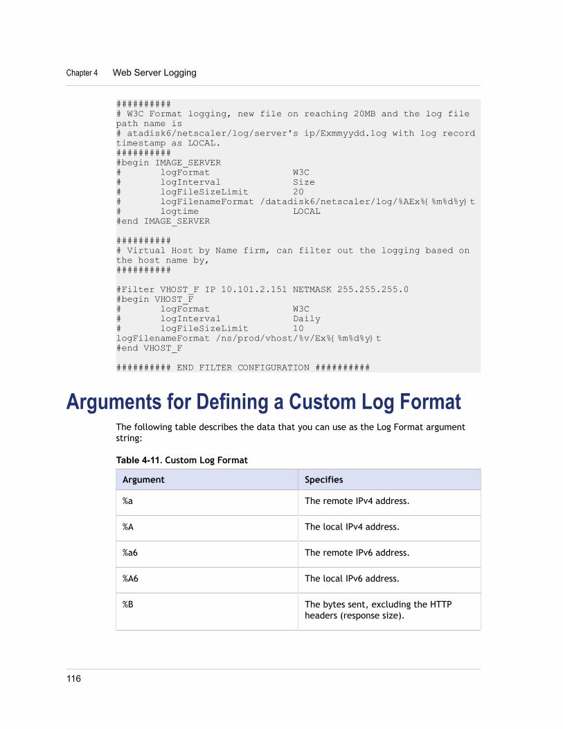
########### W3C Format logging, new file on reaching 20MB and the log file path name is# atadisk6/netscaler/log/server's ip/Exmmyydd.log with log record timestamp as LOCAL.###########begin IMAGE_SERVER# logFormat W3C# logInterval Size# logFileSizeLimit 20# logFilenameFormat /datadisk6/netscaler/log/%AEx%{%m%d%y}t# logtime LOCAL#end IMAGE_SERVER
########### Virtual Host by Name firm, can filter out the logging based on the host name by,##########
#Filter VHOST_F IP 10.101.2.151 NETMASK 255.255.255.0#begin VHOST_F# logFormat W3C# logInterval Daily# logFileSizeLimit 10logFilenameFormat /ns/prod/vhost/%v/Ex%{%m%d%y}t#end VHOST_F
########## END FILTER CONFIGURATION ##########
Arguments for Defining a Custom Log FormatThe following table describes the data that you can use as the Log Format argumentstring:
Table 4-11. Custom Log Format
Argument Specifies
%a The remote IPv4 address.
%A The local IPv4 address.
%a6 The remote IPv6 address.
%A6 The local IPv6 address.
%B The bytes sent, excluding the HTTPheaders (response size).
Chapter 4 Web Server Logging
116
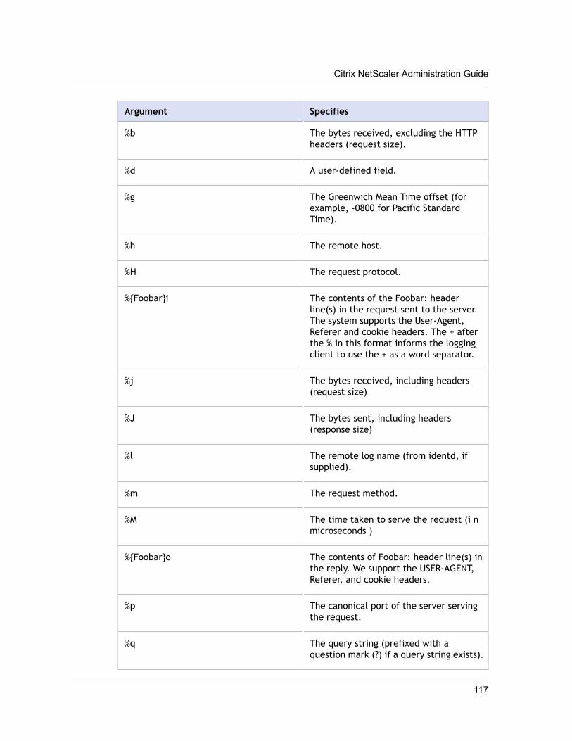
Argument Specifies
%b The bytes received, excluding the HTTPheaders (request size).
%d A user-defined field.
%g The Greenwich Mean Time offset (forexample, -0800 for Pacific StandardTime).
%h The remote host.
%H The request protocol.
%{Foobar}i The contents of the Foobar: headerline(s) in the request sent to the server.The system supports the User-Agent,Referer and cookie headers. The + afterthe % in this format informs the loggingclient to use the + as a word separator.
%j The bytes received, including headers(request size)
%J The bytes sent, including headers(response size)
%l The remote log name (from identd, ifsupplied).
%m The request method.
%M The time taken to serve the request (i nmicroseconds )
%{Foobar}o The contents of Foobar: header line(s) inthe reply. We support the USER-AGENT,Referer, and cookie headers.
%p The canonical port of the server servingthe request.
%q The query string (prefixed with aquestion mark (?) if a query string exists).
Citrix NetScaler Administration Guide
117
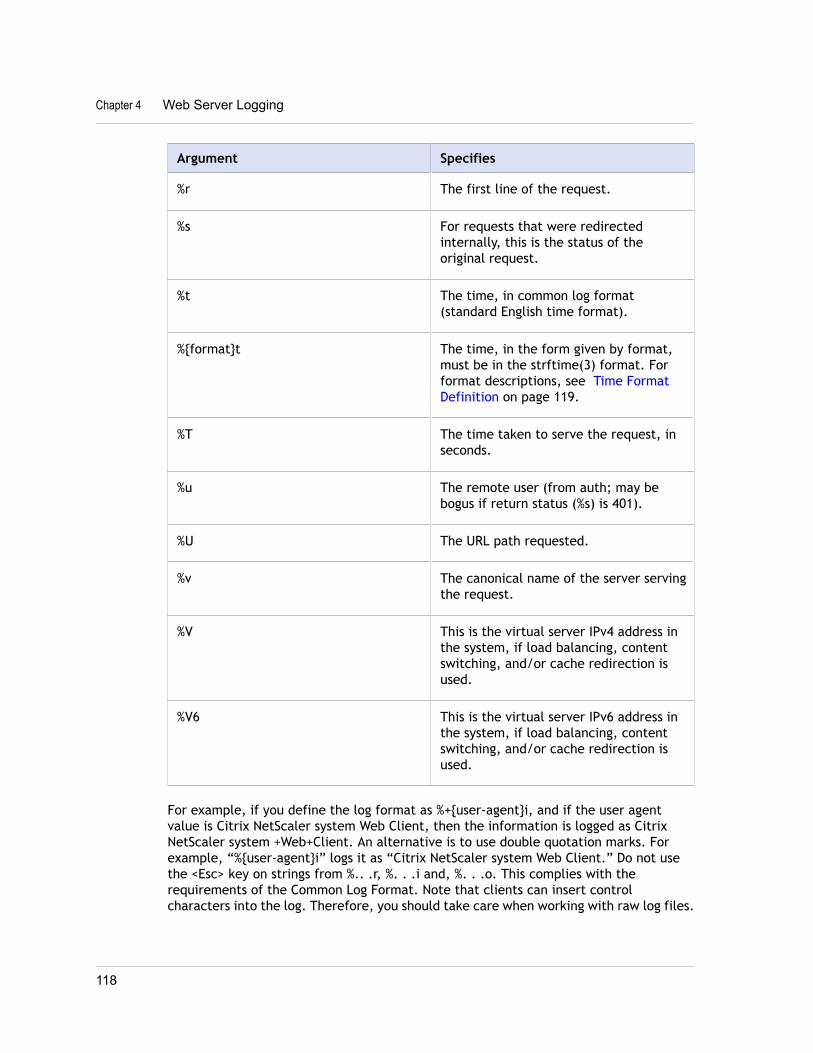
Argument Specifies
%r The first line of the request.
%s For requests that were redirectedinternally, this is the status of theoriginal request.
%t The time, in common log format(standard English time format).
%{format}t The time, in the form given by format,must be in the strftime(3) format. Forformat descriptions, see Time FormatDefinition on page 119.
%T The time taken to serve the request, inseconds.
%u The remote user (from auth; may bebogus if return status (%s) is 401).
%U The URL path requested.
%v The canonical name of the server servingthe request.
%V This is the virtual server IPv4 address inthe system, if load balancing, contentswitching, and/or cache redirection isused.
%V6 This is the virtual server IPv6 address inthe system, if load balancing, contentswitching, and/or cache redirection isused.
For example, if you define the log format as %+{user-agent}i, and if the user agentvalue is Citrix NetScaler system Web Client, then the information is logged as CitrixNetScaler system +Web+Client. An alternative is to use double quotation marks. Forexample, “%{user-agent}i” logs it as “Citrix NetScaler system Web Client.” Do not usethe <Esc> key on strings from %.. .r, %. . .i and, %. . .o. This complies with therequirements of the Common Log Format. Note that clients can insert controlcharacters into the log. Therefore, you should take care when working with raw log files.
Chapter 4 Web Server Logging
118
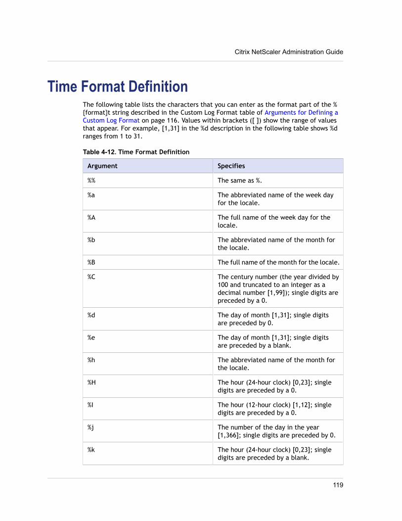
Time Format DefinitionThe following table lists the characters that you can enter as the format part of the %{format}t string described in the Custom Log Format table of Arguments for Defining aCustom Log Format on page 116. Values within brackets ([ ]) show the range of valuesthat appear. For example, [1,31] in the %d description in the following table shows %dranges from 1 to 31.
Table 4-12. Time Format Definition
Argument Specifies
%% The same as %.
%a The abbreviated name of the week dayfor the locale.
%A The full name of the week day for thelocale.
%b The abbreviated name of the month forthe locale.
%B The full name of the month for the locale.
%C The century number (the year divided by100 and truncated to an integer as adecimal number [1,99]); single digits arepreceded by a 0.
%d The day of month [1,31]; single digitsare preceded by 0.
%e The day of month [1,31]; single digitsare preceded by a blank.
%h The abbreviated name of the month forthe locale.
%H The hour (24-hour clock) [0,23]; singledigits are preceded by a 0.
%I The hour (12-hour clock) [1,12]; singledigits are preceded by a 0.
%j The number of the day in the year[1,366]; single digits are preceded by 0.
%k The hour (24-hour clock) [0,23]; singledigits are preceded by a blank.
Citrix NetScaler Administration Guide
119
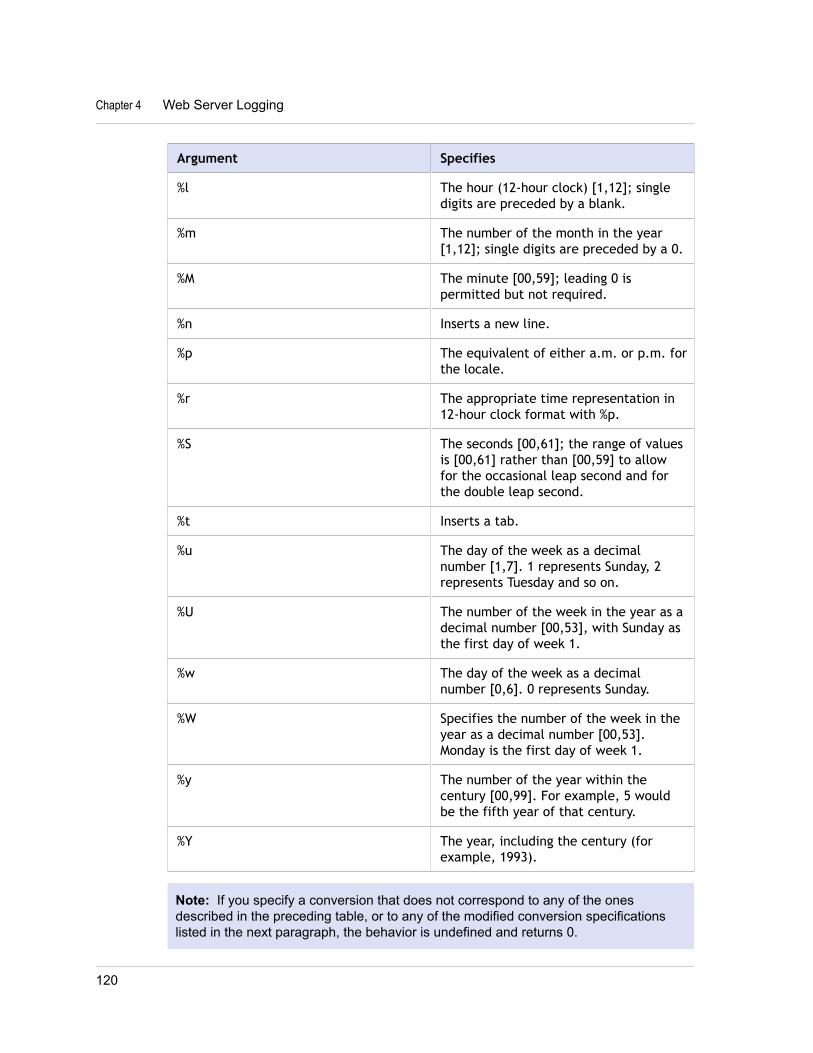
Argument Specifies
%l The hour (12-hour clock) [1,12]; singledigits are preceded by a blank.
%m The number of the month in the year[1,12]; single digits are preceded by a 0.
%M The minute [00,59]; leading 0 ispermitted but not required.
%n Inserts a new line.
%p The equivalent of either a.m. or p.m. forthe locale.
%r The appropriate time representation in12-hour clock format with %p.
%S The seconds [00,61]; the range of valuesis [00,61] rather than [00,59] to allowfor the occasional leap second and forthe double leap second.
%t Inserts a tab.
%u The day of the week as a decimalnumber [1,7]. 1 represents Sunday, 2represents Tuesday and so on.
%U The number of the week in the year as adecimal number [00,53], with Sunday asthe first day of week 1.
%w The day of the week as a decimalnumber [0,6]. 0 represents Sunday.
%W Specifies the number of the week in theyear as a decimal number [00,53].Monday is the first day of week 1.
%y The number of the year within thecentury [00,99]. For example, 5 wouldbe the fifth year of that century.
%Y The year, including the century (forexample, 1993).
Note: If you specify a conversion that does not correspond to any of the onesdescribed in the preceding table, or to any of the modified conversion specificationslisted in the next paragraph, the behavior is undefined and returns 0.
Chapter 4 Web Server Logging
120
The difference between %U and %W (and also between modified conversions %OU and%OW) is the day considered to be the first day of the week. Week number 1 is the firstweek in January (starting with a Sunday for %U, or a Monday for %W). Week number 0contains the days before the first Sunday or Monday in January for %U and %W.
Citrix NetScaler Administration Guide
121

Chapter 4 Web Server Logging
122
Chapter 5
Advanced Configurations
Topics:• Configuring Clock
Synchronization
• Viewing the System Date andTime
• Configuring TCP WindowScaling
• Configuring SelectiveAcknowledgment
• Clearing the Configuration
• Viewing the HTTP BandStatistics
• Configuring HTTP Profiles
• Configuring TCP Profiles
• Specifying a TCP Buffer Size
• Optimizing the TCP MaximumSegment Size for a VirtualServer Configuration
You can configure network time protocol to synchronize aCitrix® NetScaler® appliance's local clock with the otherservers on the network. If you enable path maximumtransmission unit (PMTU) discovery, the NetScaler can use it todetermine the maximum transmission unit of any Internetchannel. For more efficient data transfer, you can configureTCP window scaling and selective acknowledgment. You canclear any basic or extended configuration on your NetScaler.You can view statistics associated with HTTP request andresponse sizes. For applying a specific HTTP and TCP settingsto vservers and services, you can configure HTTP and TCPprofiles.
123
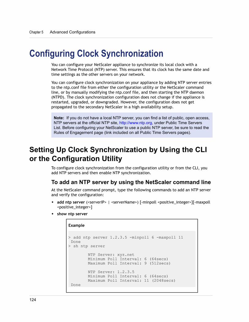
Configuring Clock SynchronizationYou can configure your NetScaler appliance to synchronize its local clock with aNetwork Time Protocol (NTP) server. This ensures that its clock has the same date andtime settings as the other servers on your network.
You can configure clock synchronization on your appliance by adding NTP server entriesto the ntp.conf file from either the configuration utility or the NetScaler commandline, or by manually modifying the ntp.conf file, and then starting the NTP daemon(NTPD). The clock synchronization configuration does not change if the appliance isrestarted, upgraded, or downgraded. However, the configuration does not getpropagated to the secondary NetScaler in a high availability setup.
Note: If you do not have a local NTP server, you can find a list of public, open access,NTP servers at the official NTP site, http://www.ntp.org, under Public Time ServersList. Before configuring your NetScaler to use a public NTP server, be sure to read theRules of Engagement page (link included on all Public Time Servers pages).
Setting Up Clock Synchronization by Using the CLIor the Configuration Utility
To configure clock synchronization from the configuration utility or from the CLI, youadd NTP servers and then enable NTP synchronization.
To add an NTP server by using the NetScaler command lineAt the NetScaler command prompt, type the following commands to add an NTP serverand verify the configuration:
w add ntp server (<serverIP> | <serverName>) [-minpoll <positive_integer>][-maxpoll<positive_integer>]
w show ntp server
Example
> add ntp server 1.2.3.5 -minpoll 6 -maxpoll 11 Done> sh ntp server
NTP Server: xyz.net Minimum Poll Interval: 6 (64secs) Maximum Poll Interval: 9 (512secs)
NTP Server: 1.2.3.5 Minimum Poll Interval: 6 (64secs) Maximum Poll Interval: 11 (2048secs) Done
Chapter 5 Advanced Configurations
124
To modify or remove NTP servers by using the NetScalercommand linew To modify settings for an NTP server, type the set ntp server (<serverIP> |
<serverName>) command and the parameters to be changed, with their new values.
w To remove an NTP server, type rm ntp server (<serverIP> | <serverName>)
Parameters for configuring an NTP serverserverIP
IP address of the NTP server.
serverNameDomain name of the NTP server.
minpollMinimum number of seconds after which the NTP server must poll the NTP messages,expressed as a power of 2. Minimum value: 4 (2^4=16 seconds). Maximum value: 17(2^17=131072 seconds). Default: 6 (2^6=64 seconds).
maxpollMaximum number of seconds after which the NTP server must poll the NTP messages,expressed as a power of 2. Minimum value: 4 (2^4=16 seconds). Maximum value: 17(2^17=131072 seconds). Default : 10 (2^10=1024 seconds).
To configure an NTP server by using the configuration utility1. In the navigation pane, expand System, and then click NTP Servers.
2. In the details pane, do one of the following:
• To add a new NTP server, click Add.
• To modify settings for an existing NTP server, select the NTP server, and thenclick Open.
3. In the Create NTP Server or Configure NTP Server dialog box, specify values forthe following parameters, which correspond to parameters described in“Parameters for configuring an NTP server” as shown:
• NTP Server*—serverIP or serverName (Cannot be changed for an existing NTPserver.)
• Minimum Poll—minpoll
• Maximum Poll—maxpoll
* A required parameter
4. Click Create or OK, and then click Close.A message appears in the status bar, stating that the NTP server has beenconfigured successfully.
Citrix NetScaler Administration Guide
125
Starting or Stopping the NTP DaemonWhen you enable NTP synchronization, the NetScaler starts the NTP daemon and usesthe NTP server entries in the ntp.conf file to synchronize its local time setting. If youdo not want to synchronize your NetScaler time with the other servers in the network,you can disable NTP synchronization, which stops the NTP daemon (NTPD).
To enable or disable NTP synchronization by using theNetScaler command lineAt the NetScaler command prompt, type one of the following commands:
w enable ntp sync
w disable ntp sync
To enable or disable NTP synchronization by using theconfiguration utility1. In the navigation pane, expand System, and then click NTP Servers.
2. On the NTP Servers page, click NTP Synchronization – ON or NTPSynchronization – OFF.
Configuring Clock Synchronization ManuallyYou can configure clock synchronization manually by logging on to the NetScaler andediting the ntp.conf file.
To enable clock synchronization on your NetScaler bymodifying the ntp.conf file1. Log on to the NetScaler command line.
2. Switch to the shell prompt.
3. Copy the /etc/ntp.conf file to /nsconfig/ntp.conf, unless the /nsconfig directoryalready contains an ntp.conf file.
4. Check the /nsconfig/ntp.conf file for the following entries and, if they arepresent, remove them:
restrict localhost
restrict 127.0.0.2
5. Add the IP address for the desired NTP server to the /nsconfig/ntp.conf file,beneath the file’s server and restrict entries.
Note: For security reasons, there should be a corresponding restrict entry foreach server entry.
Chapter 5 Advanced Configurations
126
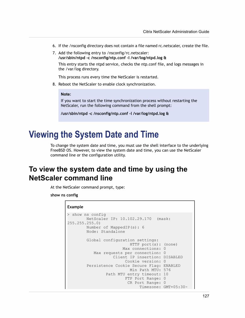
6. If the /nsconfig directory does not contain a file named rc.netscaler, create the file.
7. Add the following entry to /nsconfig/rc.netscaler:/usr/sbin/ntpd -c /nsconfig/ntp.conf -l /var/log/ntpd.log &
This entry starts the ntpd service, checks the ntp.conf file, and logs messages inthe /var/log directory.
This process runs every time the NetScaler is restarted.
8. Reboot the NetScaler to enable clock synchronization.
Note:If you want to start the time synchronization process without restarting theNetScaler, run the following command from the shell prompt:
/usr/sbin/ntpd -c /nsconfig/ntp.conf -l /var/log/ntpd.log &
Viewing the System Date and TimeTo change the system date and time, you must use the shell interface to the underlyingFreeBSD OS. However, to view the system date and time, you can use the NetScalercommand line or the configuration utility.
To view the system date and time by using theNetScaler command line
At the NetScaler command prompt, type:
show ns config
Example
> show ns config NetScaler IP: 10.102.29.170 (mask: 255.255.255.0) Number of MappedIP(s): 6 Node: Standalone
Global configuration settings: HTTP port(s): (none) Max connections: 0 Max requests per connection: 0 Client IP insertion: DISABLED Cookie version: 0 Persistence Cookie Secure Flag: ENABLED Min Path MTU: 576 Path MTU entry timeout: 10 FTP Port Range: 0 CR Port Range: 0 Timezone: GMT+05:30-
Citrix NetScaler Administration Guide
127
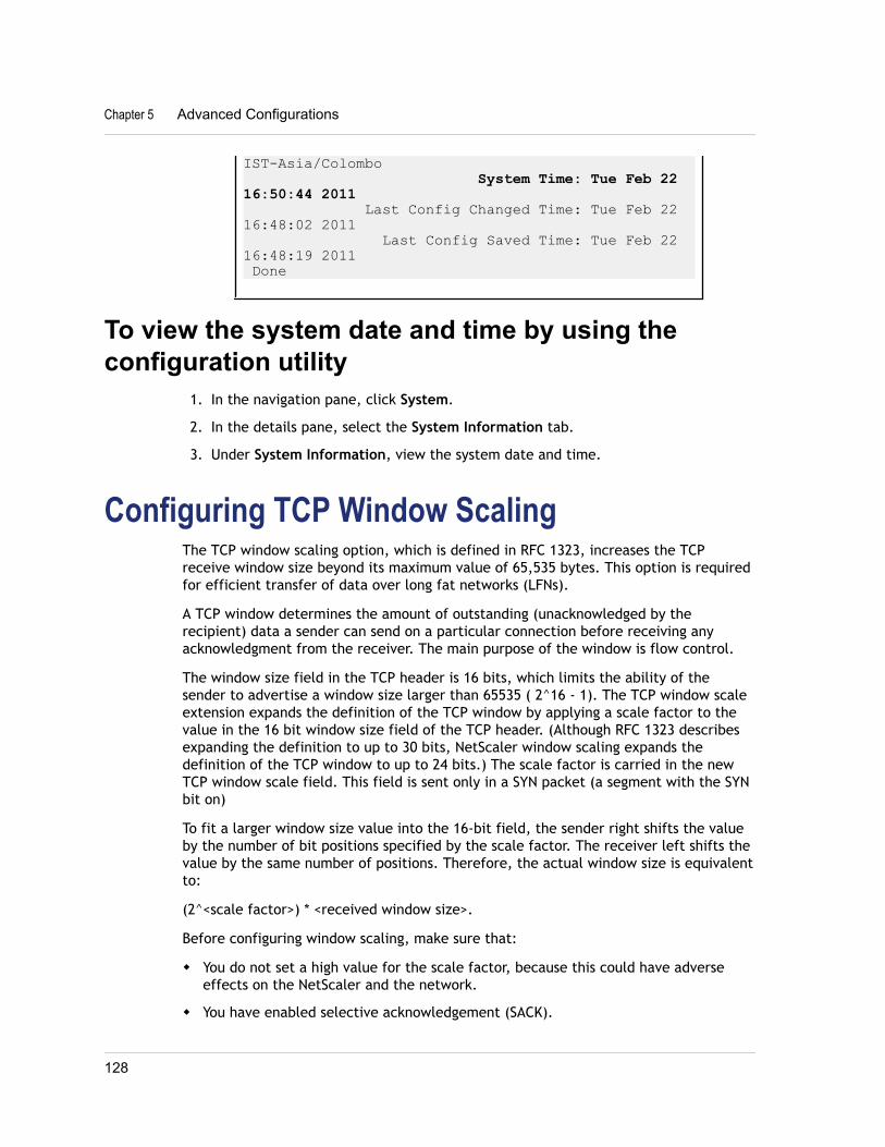
IST-Asia/Colombo System Time: Tue Feb 22 16:50:44 2011 Last Config Changed Time: Tue Feb 22 16:48:02 2011 Last Config Saved Time: Tue Feb 22 16:48:19 2011 Done
To view the system date and time by using theconfiguration utility
1. In the navigation pane, click System.
2. In the details pane, select the System Information tab.
3. Under System Information, view the system date and time.
Configuring TCP Window ScalingThe TCP window scaling option, which is defined in RFC 1323, increases the TCPreceive window size beyond its maximum value of 65,535 bytes. This option is requiredfor efficient transfer of data over long fat networks (LFNs).
A TCP window determines the amount of outstanding (unacknowledged by therecipient) data a sender can send on a particular connection before receiving anyacknowledgment from the receiver. The main purpose of the window is flow control.
The window size field in the TCP header is 16 bits, which limits the ability of thesender to advertise a window size larger than 65535 ( 2^16 - 1). The TCP window scaleextension expands the definition of the TCP window by applying a scale factor to thevalue in the 16 bit window size field of the TCP header. (Although RFC 1323 describesexpanding the definition to up to 30 bits, NetScaler window scaling expands thedefinition of the TCP window to up to 24 bits.) The scale factor is carried in the newTCP window scale field. This field is sent only in a SYN packet (a segment with the SYNbit on)
To fit a larger window size value into the 16-bit field, the sender right shifts the valueby the number of bit positions specified by the scale factor. The receiver left shifts thevalue by the same number of positions. Therefore, the actual window size is equivalentto:
(2^<scale factor>) * <received window size>.
Before configuring window scaling, make sure that:
w You do not set a high value for the scale factor, because this could have adverseeffects on the NetScaler and the network.
w You have enabled selective acknowledgement (SACK).
Chapter 5 Advanced Configurations
128
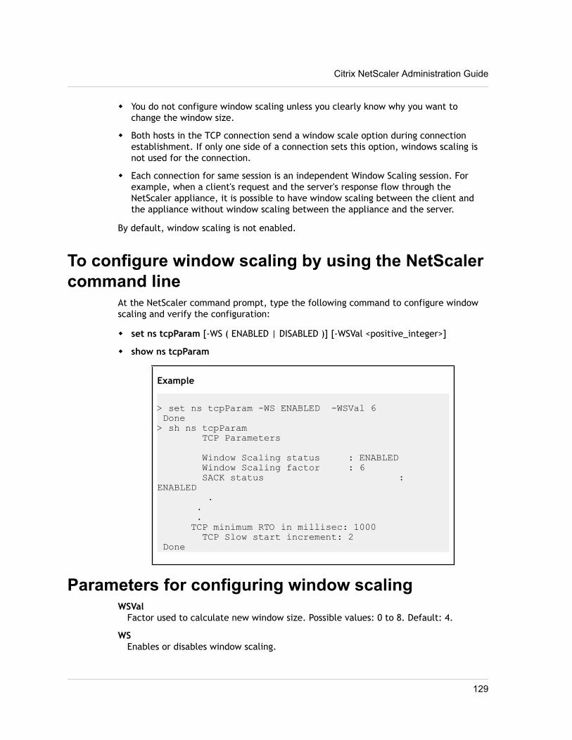
w You do not configure window scaling unless you clearly know why you want tochange the window size.
w Both hosts in the TCP connection send a window scale option during connectionestablishment. If only one side of a connection sets this option, windows scaling isnot used for the connection.
w Each connection for same session is an independent Window Scaling session. Forexample, when a client's request and the server's response flow through theNetScaler appliance, it is possible to have window scaling between the client andthe appliance without window scaling between the appliance and the server.
By default, window scaling is not enabled.
To configure window scaling by using the NetScalercommand line
At the NetScaler command prompt, type the following command to configure windowscaling and verify the configuration:
w set ns tcpParam [-WS ( ENABLED | DISABLED )] [-WSVal <positive_integer>]
w show ns tcpParam
Example
> set ns tcpParam -WS ENABLED -WSVal 6 Done> sh ns tcpParam TCP Parameters
Window Scaling status : ENABLED Window Scaling factor : 6 SACK status : ENABLED . . . TCP minimum RTO in millisec: 1000 TCP Slow start increment: 2 Done
Parameters for configuring window scalingWSVal
Factor used to calculate new window size. Possible values: 0 to 8. Default: 4.
WSEnables or disables window scaling.
Citrix NetScaler Administration Guide
129
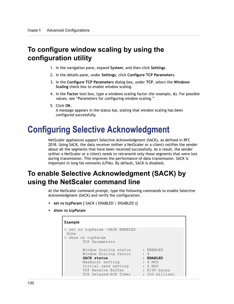
To configure window scaling by using theconfiguration utility
1. In the navigation pane, expand System, and then click Settings.
2. In the details pane, under Settings, click Configure TCP Parameters.
3. In the Configure TCP Parameters dialog box, under TCP, select the WindowsScaling check box to enable window scaling.
4. In the Factor text box, type a windows scaling factor (for example, 6). For possiblevalues, see “Parameters for configuring window scaling.”
5. Click OK.A message appears in the status bar, stating that window scaling has beenconfigured successfully.
Configuring Selective AcknowledgmentNetScaler appliances support Selective Acknowledgment (SACK), as defined in RFC2018. Using SACK, the data receiver (either a NetScaler or a client) notifies the senderabout all the segments that have been received successfully. As a result, the sender(either a NetScaler or a client) needs to retransmit only those segments that were lostduring transmission. This improves the performance of data transmission. SACK isimportant in long fat networks (LFNs). By default, SACK is disabled.
To enable Selective Acknowledgment (SACK) byusing the NetScaler command line
At the NetScaler command prompt, type the following commands to enable SelectiveAcknowledgment (SACK) and verify the configuration:
w set ns tcpParam [-SACK ( ENABLED | DISABLED )]
w show ns tcpParam
Example
> set ns tcpParam -SACK ENABLED Done> show ns tcpParam TCP Parameters
Window Scaling status : ENABLED Window Scaling factor : 4 SACK status : ENABLED MaxBurst setting : 6 MSS Initial cwnd setting : 4 MSS TCP Receive Buffer : 8190 bytes TCP Delayed-ACK Timer : 200 millisec
Chapter 5 Advanced Configurations
130
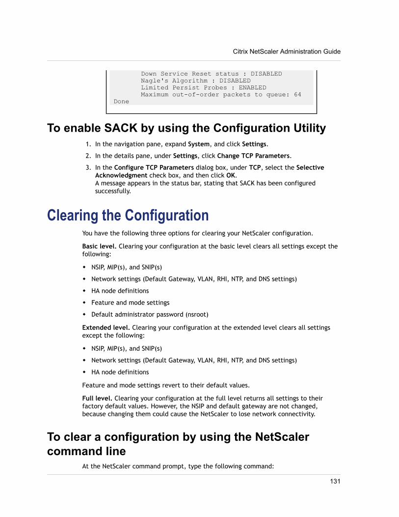
Down Service Reset status : DISABLED Nagle's Algorithm : DISABLED Limited Persist Probes : ENABLED Maximum out-of-order packets to queue: 64 Done
To enable SACK by using the Configuration Utility1. In the navigation pane, expand System, and click Settings.
2. In the details pane, under Settings, click Change TCP Parameters.
3. In the Configure TCP Parameters dialog box, under TCP, select the SelectiveAcknowledgment check box, and then click OK.A message appears in the status bar, stating that SACK has been configuredsuccessfully.
Clearing the ConfigurationYou have the following three options for clearing your NetScaler configuration.
Basic level. Clearing your configuration at the basic level clears all settings except thefollowing:
w NSIP, MIP(s), and SNIP(s)
w Network settings (Default Gateway, VLAN, RHI, NTP, and DNS settings)
w HA node definitions
w Feature and mode settings
w Default administrator password (nsroot)
Extended level. Clearing your configuration at the extended level clears all settingsexcept the following:
w NSIP, MIP(s), and SNIP(s)
w Network settings (Default Gateway, VLAN, RHI, NTP, and DNS settings)
w HA node definitions
Feature and mode settings revert to their default values.
Full level. Clearing your configuration at the full level returns all settings to theirfactory default values. However, the NSIP and default gateway are not changed,because changing them could cause the NetScaler to lose network connectivity.
To clear a configuration by using the NetScalercommand line
At the NetScaler command prompt, type the following command:
Citrix NetScaler Administration Guide
131

clear ns config < ( basic | advanced | full )>
Example
> clear ns config basicAre you sure you want to clear the configuration(Y/N)? [N]:Y Done
Parameters for clearing a configurationlevel
A level representing the extent to which to clear the configuration. Possible values:basic, extended, full.
To clear a configuration by using the configurationutility
1. In the navigation pane, expand System, and then click Diagnostics.
2. In the details pane, under Maintenance, click Clear Configuration.
3. In the Clear Configuration dialog box, for Configuration Level, select an option(for example, basic).
4. Click Run. A message appears in the status bar, stating that the configuration hasbeen refreshed successfully.
Viewing the HTTP Band StatisticsYou can view HTTP band statistics to obtain useful information such as:
w Average request/response band size.
w The size range to which most requests/responses belong.
w Contribution of HTTP pages, in a certain size range, to the overall HTTP traffic.
To view HTTP request and response size statisticsby using the NetScaler command line
At the NetScaler command prompt, type:
show protocol httpBand –type (REQUEST|RESPONSE)
Chapter 5 Advanced Configurations
132
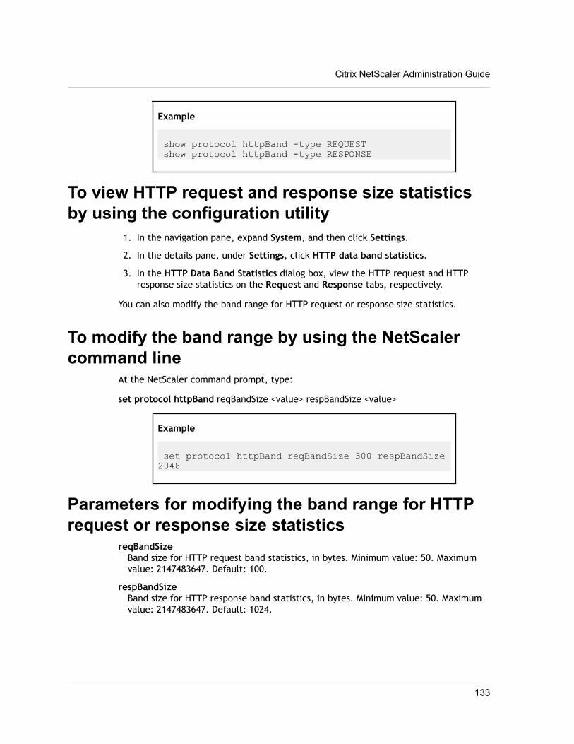
Example
show protocol httpBand -type REQUEST show protocol httpBand -type RESPONSE
To view HTTP request and response size statisticsby using the configuration utility
1. In the navigation pane, expand System, and then click Settings.
2. In the details pane, under Settings, click HTTP data band statistics.
3. In the HTTP Data Band Statistics dialog box, view the HTTP request and HTTPresponse size statistics on the Request and Response tabs, respectively.
You can also modify the band range for HTTP request or response size statistics.
To modify the band range by using the NetScalercommand line
At the NetScaler command prompt, type:
set protocol httpBand reqBandSize <value> respBandSize <value>
Example
set protocol httpBand reqBandSize 300 respBandSize 2048
Parameters for modifying the band range for HTTPrequest or response size statistics
reqBandSizeBand size for HTTP request band statistics, in bytes. Minimum value: 50. Maximumvalue: 2147483647. Default: 100.
respBandSizeBand size for HTTP response band statistics, in bytes. Minimum value: 50. Maximumvalue: 2147483647. Default: 1024.
Citrix NetScaler Administration Guide
133
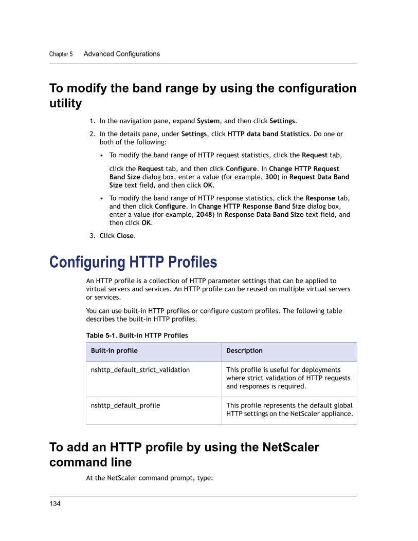
To modify the band range by using the configurationutility
1. In the navigation pane, expand System, and then click Settings.
2. In the details pane, under Settings, click HTTP data band Statistics. Do one orboth of the following:
• To modify the band range of HTTP request statistics, click the Request tab,
click the Request tab, and then click Configure. In Change HTTP RequestBand Size dialog box, enter a value (for example, 300) in Request Data BandSize text field, and then click OK.
• To modify the band range of HTTP response statistics, click the Response tab,and then click Configure. In Change HTTP Response Band Size dialog box,enter a value (for example, 2048) in Response Data Band Size text field, andthen click OK.
3. Click Close.
Configuring HTTP ProfilesAn HTTP profile is a collection of HTTP parameter settings that can be applied tovirtual servers and services. An HTTP profile can be reused on multiple virtual serversor services.
You can use built-in HTTP profiles or configure custom profiles. The following tabledescribes the built-in HTTP profiles.
Table 5-1. Built-in HTTP Profiles
Built-in profile Description
nshttp_default_strict_validation This profile is useful for deploymentswhere strict validation of HTTP requestsand responses is required.
nshttp_default_profile This profile represents the default globalHTTP settings on the NetScaler appliance.
To add an HTTP profile by using the NetScalercommand line
At the NetScaler command prompt, type:
Chapter 5 Advanced Configurations
134
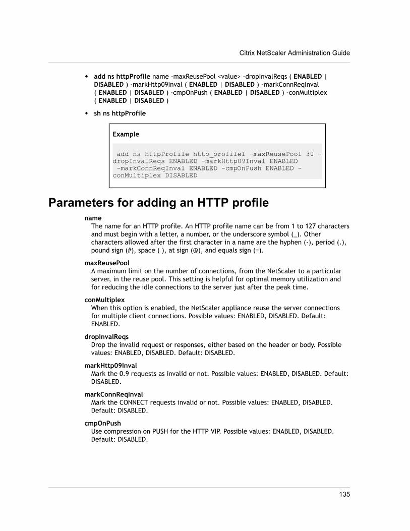
w add ns httpProfile name -maxReusePool <value> -dropInvalReqs ( ENABLED |DISABLED ) -markHttp09Inval ( ENABLED | DISABLED ) -markConnReqInval( ENABLED | DISABLED ) -cmpOnPush ( ENABLED | DISABLED ) -conMultiplex( ENABLED | DISABLED )
w sh ns httpProfile
Example
add ns httpProfile http_profile1 -maxReusePool 30 -dropInvalReqs ENABLED -markHttp09Inval ENABLED -markConnReqInval ENABLED -cmpOnPush ENABLED -conMultiplex DISABLED
Parameters for adding an HTTP profilename
The name for an HTTP profile. An HTTP profile name can be from 1 to 127 charactersand must begin with a letter, a number, or the underscore symbol (_). Othercharacters allowed after the first character in a name are the hyphen (-), period (.),pound sign (#), space ( ), at sign (@), and equals sign (=).
maxReusePoolA maximum limit on the number of connections, from the NetScaler to a particularserver, in the reuse pool. This setting is helpful for optimal memory utilization andfor reducing the idle connections to the server just after the peak time.
conMultiplexWhen this option is enabled, the NetScaler appliance reuse the server connectionsfor multiple client connections. Possible values: ENABLED, DISABLED. Default:ENABLED.
dropInvalReqsDrop the invalid request or responses, either based on the header or body. Possiblevalues: ENABLED, DISABLED. Default: DISABLED.
markHttp09InvalMark the 0.9 requests as invalid or not. Possible values: ENABLED, DISABLED. Default:DISABLED.
markConnReqInvalMark the CONNECT requests invalid or not. Possible values: ENABLED, DISABLED.Default: DISABLED.
cmpOnPushUse compression on PUSH for the HTTP VIP. Possible values: ENABLED, DISABLED.Default: DISABLED.
Citrix NetScaler Administration Guide
135
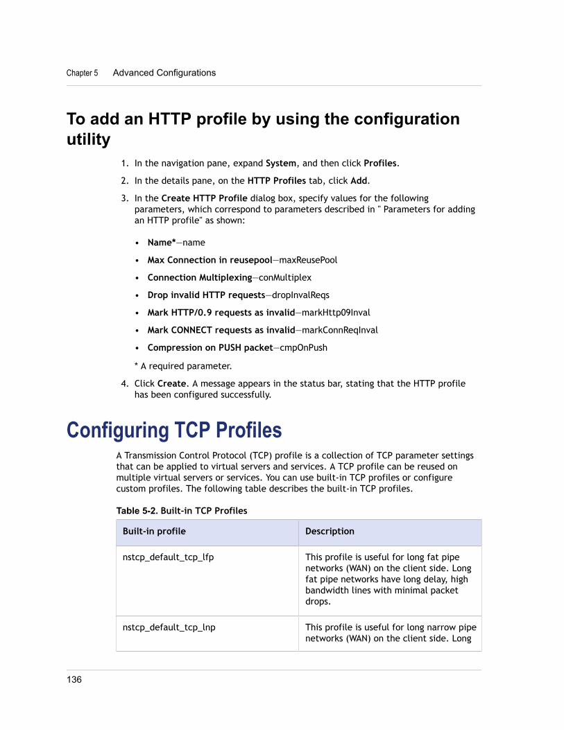
To add an HTTP profile by using the configurationutility
1. In the navigation pane, expand System, and then click Profiles.
2. In the details pane, on the HTTP Profiles tab, click Add.
3. In the Create HTTP Profile dialog box, specify values for the followingparameters, which correspond to parameters described in " Parameters for addingan HTTP profile" as shown:
• Name*—name
• Max Connection in reusepool—maxReusePool
• Connection Multiplexing—conMultiplex
• Drop invalid HTTP requests—dropInvalReqs
• Mark HTTP/0.9 requests as invalid—markHttp09Inval
• Mark CONNECT requests as invalid—markConnReqInval
• Compression on PUSH packet—cmpOnPush
* A required parameter.
4. Click Create. A message appears in the status bar, stating that the HTTP profilehas been configured successfully.
Configuring TCP ProfilesA Transmission Control Protocol (TCP) profile is a collection of TCP parameter settingsthat can be applied to virtual servers and services. A TCP profile can be reused onmultiple virtual servers or services. You can use built-in TCP profiles or configurecustom profiles. The following table describes the built-in TCP profiles.
Table 5-2. Built-in TCP Profiles
Built-in profile Description
nstcp_default_tcp_lfp This profile is useful for long fat pipenetworks (WAN) on the client side. Longfat pipe networks have long delay, highbandwidth lines with minimal packetdrops.
nstcp_default_tcp_lnp This profile is useful for long narrow pipenetworks (WAN) on the client side. Long
Chapter 5 Advanced Configurations
136
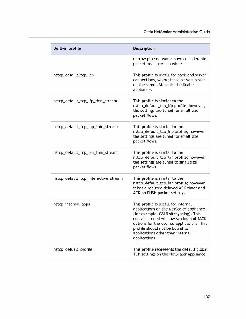
Built-in profile Description
narrow pipe networks have considerablepacket loss once in a while.
nstcp_default_tcp_lan This profile is useful for back-end serverconnections, where these servers resideon the same LAN as the NetScalerappliance.
nstcp_default_tcp_lfp_thin_stream This profile is similar to thenstcp_default_tcp_lfp profile; however,the settings are tuned for small sizepacket flows.
nstcp_default_tcp_lnp_thin_stream This profile is similar to thenstcp_default_tcp_lnp profile; however,the settings are tuned for small sizepacket flows.
nstcp_default_tcp_lan_thin_stream This profile is similar to thenstcp_default_tcp_lan profile; however,the settings are tuned to small sizepacket flows.
nstcp_default_tcp_interactive_stream This profile is similar to thenstcp_default_tcp_lan profile; however,it has a reduced delayed ACK timer andACK on PUSH packet settings.
nstcp_internal_apps This profile is useful for internalapplications on the NetScaler appliance(for example, GSLB sitesyncing). Thiscontains tuned window scaling and SACKoptions for the desired applications. Thisprofile should not be bound toapplications other than internalapplications.
nstcp_defualt_profile This profile represents the default globalTCP settings on the NetScaler appliance.
Citrix NetScaler Administration Guide
137
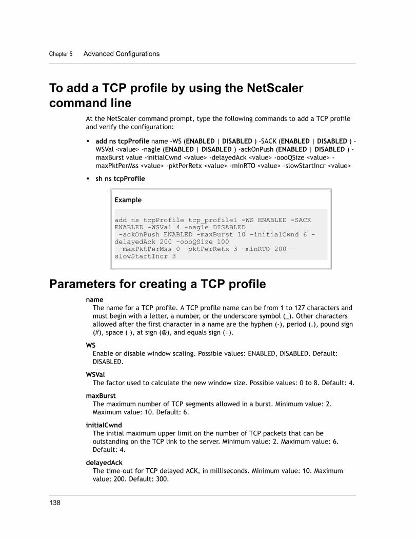
To add a TCP profile by using the NetScalercommand line
At the NetScaler command prompt, type the following commands to add a TCP profileand verify the configuration:
w add ns tcpProfile name -WS (ENABLED | DISABLED ) -SACK (ENABLED | DISABLED ) -WSVal <value> -nagle (ENABLED | DISABLED ) -ackOnPush (ENABLED | DISABLED ) -maxBurst value -initialCwnd <value> -delayedAck <value> -oooQSize <value> -maxPktPerMss <value> -pktPerRetx <value> -minRTO <value> -slowStartIncr <value>
w sh ns tcpProfile
Example
add ns tcpProfile tcp_profile1 -WS ENABLED -SACK ENABLED -WSVal 4 -nagle DISABLED -ackOnPush ENABLED -maxBurst 10 -initialCwnd 6 -delayedAck 200 -oooQSize 100 -maxPktPerMss 0 -pktPerRetx 3 -minRTO 200 -slowStartIncr 3
Parameters for creating a TCP profilename
The name for a TCP profile. A TCP profile name can be from 1 to 127 characters andmust begin with a letter, a number, or the underscore symbol (_). Other charactersallowed after the first character in a name are the hyphen (-), period (.), pound sign(#), space ( ), at sign (@), and equals sign (=).
WSEnable or disable window scaling. Possible values: ENABLED, DISABLED. Default:DISABLED.
WSValThe factor used to calculate the new window size. Possible values: 0 to 8. Default: 4.
maxBurstThe maximum number of TCP segments allowed in a burst. Minimum value: 2.Maximum value: 10. Default: 6.
initialCwndThe initial maximum upper limit on the number of TCP packets that can beoutstanding on the TCP link to the server. Minimum value: 2. Maximum value: 6.Default: 4.
delayedAckThe time-out for TCP delayed ACK, in milliseconds. Minimum value: 10. Maximumvalue: 200. Default: 300.
Chapter 5 Advanced Configurations
138
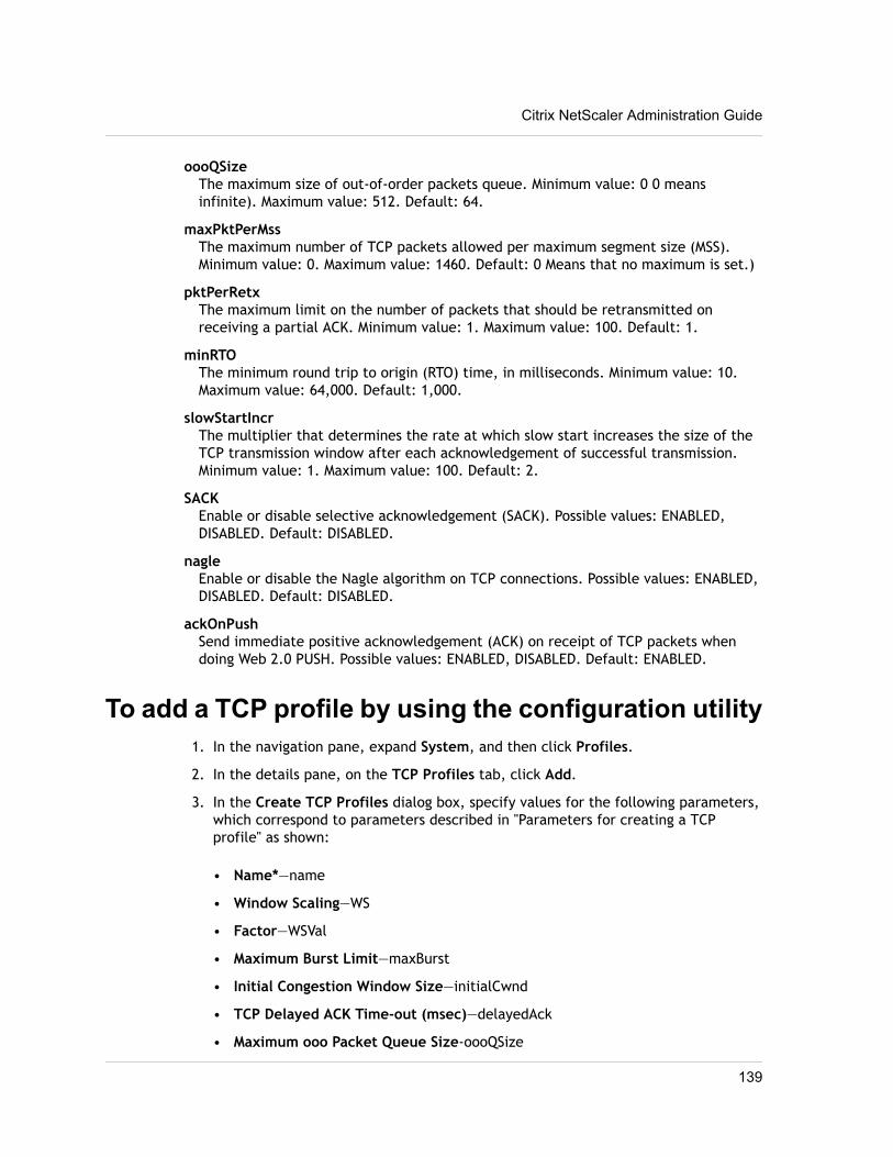
oooQSizeThe maximum size of out-of-order packets queue. Minimum value: 0 0 meansinfinite). Maximum value: 512. Default: 64.
maxPktPerMssThe maximum number of TCP packets allowed per maximum segment size (MSS).Minimum value: 0. Maximum value: 1460. Default: 0 Means that no maximum is set.)
pktPerRetxThe maximum limit on the number of packets that should be retransmitted onreceiving a partial ACK. Minimum value: 1. Maximum value: 100. Default: 1.
minRTOThe minimum round trip to origin (RTO) time, in milliseconds. Minimum value: 10.Maximum value: 64,000. Default: 1,000.
slowStartIncrThe multiplier that determines the rate at which slow start increases the size of theTCP transmission window after each acknowledgement of successful transmission.Minimum value: 1. Maximum value: 100. Default: 2.
SACKEnable or disable selective acknowledgement (SACK). Possible values: ENABLED,DISABLED. Default: DISABLED.
nagleEnable or disable the Nagle algorithm on TCP connections. Possible values: ENABLED,DISABLED. Default: DISABLED.
ackOnPushSend immediate positive acknowledgement (ACK) on receipt of TCP packets whendoing Web 2.0 PUSH. Possible values: ENABLED, DISABLED. Default: ENABLED.
To add a TCP profile by using the configuration utility1. In the navigation pane, expand System, and then click Profiles.
2. In the details pane, on the TCP Profiles tab, click Add.
3. In the Create TCP Profiles dialog box, specify values for the following parameters,which correspond to parameters described in "Parameters for creating a TCPprofile" as shown:
• Name*—name
• Window Scaling—WS
• Factor—WSVal
• Maximum Burst Limit—maxBurst
• Initial Congestion Window Size—initialCwnd
• TCP Delayed ACK Time-out (msec)—delayedAck
• Maximum ooo Packet Queue Size-oooQSize
Citrix NetScaler Administration Guide
139
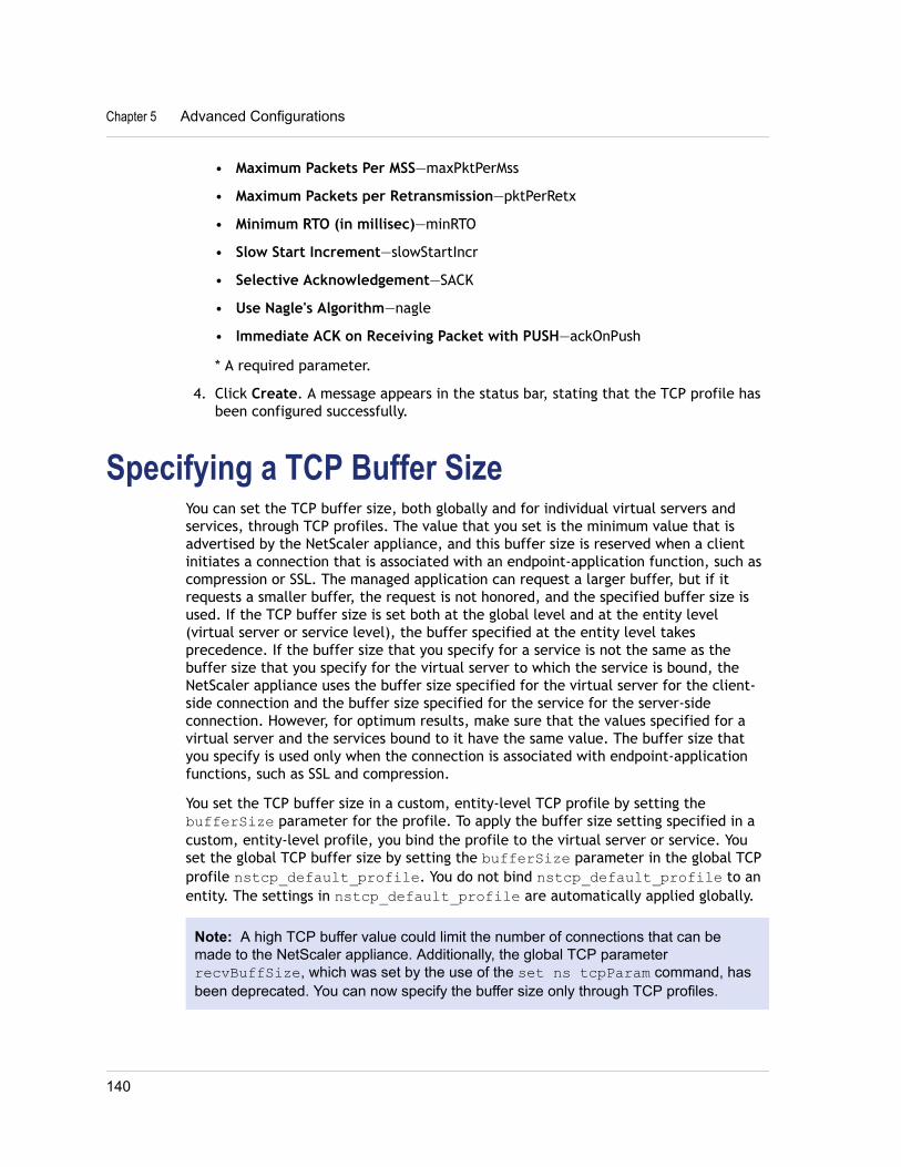
• Maximum Packets Per MSS—maxPktPerMss
• Maximum Packets per Retransmission—pktPerRetx
• Minimum RTO (in millisec)—minRTO
• Slow Start Increment—slowStartIncr
• Selective Acknowledgement—SACK
• Use Nagle's Algorithm—nagle
• Immediate ACK on Receiving Packet with PUSH—ackOnPush
* A required parameter.
4. Click Create. A message appears in the status bar, stating that the TCP profile hasbeen configured successfully.
Specifying a TCP Buffer SizeYou can set the TCP buffer size, both globally and for individual virtual servers andservices, through TCP profiles. The value that you set is the minimum value that isadvertised by the NetScaler appliance, and this buffer size is reserved when a clientinitiates a connection that is associated with an endpoint-application function, such ascompression or SSL. The managed application can request a larger buffer, but if itrequests a smaller buffer, the request is not honored, and the specified buffer size isused. If the TCP buffer size is set both at the global level and at the entity level(virtual server or service level), the buffer specified at the entity level takesprecedence. If the buffer size that you specify for a service is not the same as thebuffer size that you specify for the virtual server to which the service is bound, theNetScaler appliance uses the buffer size specified for the virtual server for the client-side connection and the buffer size specified for the service for the server-sideconnection. However, for optimum results, make sure that the values specified for avirtual server and the services bound to it have the same value. The buffer size thatyou specify is used only when the connection is associated with endpoint-applicationfunctions, such as SSL and compression.
You set the TCP buffer size in a custom, entity-level TCP profile by setting thebufferSize parameter for the profile. To apply the buffer size setting specified in acustom, entity-level profile, you bind the profile to the virtual server or service. Youset the global TCP buffer size by setting the bufferSize parameter in the global TCPprofile nstcp_default_profile. You do not bind nstcp_default_profile to anentity. The settings in nstcp_default_profile are automatically applied globally.
Note: A high TCP buffer value could limit the number of connections that can bemade to the NetScaler appliance. Additionally, the global TCP parameterrecvBuffSize, which was set by the use of the set ns tcpParam command, hasbeen deprecated. You can now specify the buffer size only through TCP profiles.
Chapter 5 Advanced Configurations
140
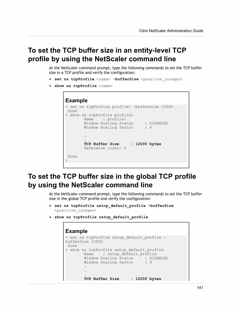
To set the TCP buffer size in an entity-level TCPprofile by using the NetScaler command line
At the NetScaler command prompt, type the following commands to set the TCP buffersize in a TCP profile and verify the configuration:
w set ns tcpProfile <name> -bufferSize <positive_integer>w show ns tcpProfile <name>
Example> set ns tcpProfile profile1 -bufferSize 12000 Done> show ns tcpProfile profile1 Name : profile1 Window Scaling status : DISABLED Window Scaling factor : 4 . . . TCP Buffer Size : 12000 bytes Reference count: 0
Done>
To set the TCP buffer size in the global TCP profileby using the NetScaler command line
At the NetScaler command prompt, type the following commands to set the TCP buffersize in the global TCP profile and verify the configuration:
w set ns tcpProfile nstcp_default_profile –bufferSize<positive_integer>
w show ns tcpProfile nstcp_default_profile
Example> set ns tcpProfile nstcp_default_profile -bufferSize 12000 Done> show ns tcpProfile nstcp_default_profile Name : nstcp_default_profile Window Scaling status : DISABLED Window Scaling factor : 4 . . . TCP Buffer Size : 12000 bytes
Citrix NetScaler Administration Guide
141
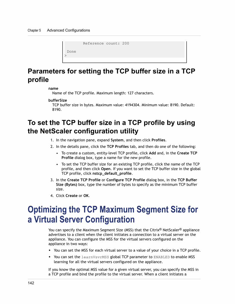
Reference count: 200
Done>
Parameters for setting the TCP buffer size in a TCPprofile
nameName of the TCP profile. Maximum length: 127 characters.
bufferSizeTCP buffer size in bytes. Maximum value: 4194304. Minimum value: 8190. Default:8190.
To set the TCP buffer size in a TCP profile by usingthe NetScaler configuration utility
1. In the navigation pane, expand System, and then click Profiles.
2. In the details pane, click the TCP Profiles tab, and then do one of the following:
• To create a custom, entity-level TCP profile, click Add and, in the Create TCPProfile dialog box, type a name for the new profile.
• To set the TCP buffer size for an existing TCP profile, click the name of the TCPprofile, and then click Open. If you want to set the TCP buffer size in the globalTCP profile, click nstcp_default_profile.
3. In the Create TCP Profile or Configure TCP Profile dialog box, in the TCP BufferSize (Bytes) box, type the number of bytes to specify as the minimum TCP buffersize.
4. Click Create or OK.
Optimizing the TCP Maximum Segment Size fora Virtual Server Configuration
You can specify the Maximum Segment Size (MSS) that the Citrix® NetScaler® applianceadvertises to a client when the client initiates a connection to a virtual server on theappliance. You can configure the MSS for the virtual servers configured on theappliance in two ways:
w You can set the MSS for each virtual server to a value of your choice in a TCP profile.
w You can set the learnVsvrMSS global TCP parameter to ENABLED to enable MSSlearning for all the virtual servers configured on the appliance.
If you know the optimal MSS value for a given virtual server, you can specify the MSS ina TCP profile and bind the profile to the virtual server. When a client initiates a
Chapter 5 Advanced Configurations
142
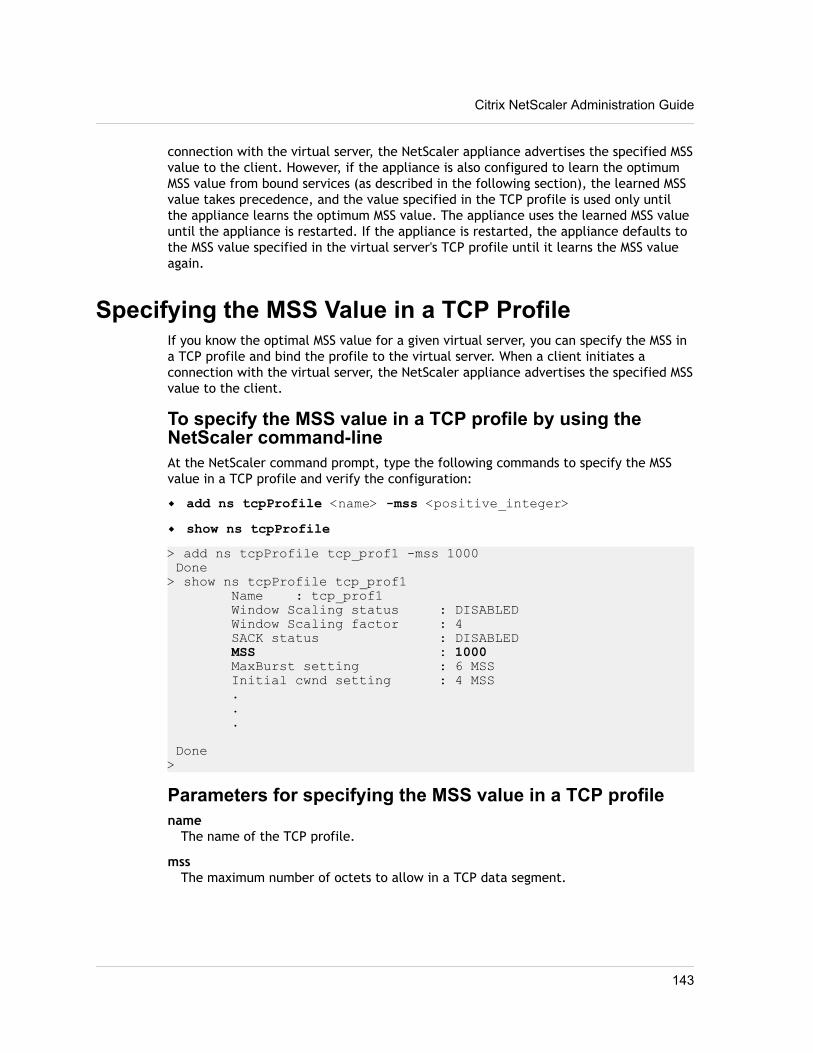
connection with the virtual server, the NetScaler appliance advertises the specified MSSvalue to the client. However, if the appliance is also configured to learn the optimumMSS value from bound services (as described in the following section), the learned MSSvalue takes precedence, and the value specified in the TCP profile is used only untilthe appliance learns the optimum MSS value. The appliance uses the learned MSS valueuntil the appliance is restarted. If the appliance is restarted, the appliance defaults tothe MSS value specified in the virtual server's TCP profile until it learns the MSS valueagain.
Specifying the MSS Value in a TCP ProfileIf you know the optimal MSS value for a given virtual server, you can specify the MSS ina TCP profile and bind the profile to the virtual server. When a client initiates aconnection with the virtual server, the NetScaler appliance advertises the specified MSSvalue to the client.
To specify the MSS value in a TCP profile by using theNetScaler command-lineAt the NetScaler command prompt, type the following commands to specify the MSSvalue in a TCP profile and verify the configuration:
w add ns tcpProfile <name> -mss <positive_integer>w show ns tcpProfile> add ns tcpProfile tcp_prof1 -mss 1000 Done> show ns tcpProfile tcp_prof1 Name : tcp_prof1 Window Scaling status : DISABLED Window Scaling factor : 4 SACK status : DISABLED MSS : 1000 MaxBurst setting : 6 MSS Initial cwnd setting : 4 MSS . . .
Done>
Parameters for specifying the MSS value in a TCP profilename
The name of the TCP profile.
mssThe maximum number of octets to allow in a TCP data segment.
Citrix NetScaler Administration Guide
143
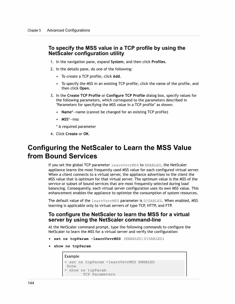
To specify the MSS value in a TCP profile by using theNetScaler configuration utility1. In the navigation pane, expand System, and then click Profiles.
2. In the details pane, do one of the following:
• To create a TCP profile, click Add.
• To specify the MSS in an existing TCP profile, click the name of the profile, andthen click Open.
3. In the Create TCP Profile or Configure TCP Profile dialog box, specify values forthe following parameters, which correspond to the parameters described in"Parameters for specifying the MSS value in a TCP profile" as shown:
• Name*—name (cannot be changed for an existing TCP profile)
• MSS*—mss
* A required parameter
4. Click Create or OK.
Configuring the NetScaler to Learn the MSS Valuefrom Bound Services
If you set the global TCP parameter learnVsvrMSS to ENABLED, the NetScalerappliance learns the most frequently used MSS value for each configured virtual server.When a client connects to a virtual server, the appliance advertises to the client theMSS value that is optimum for that virtual server. The optimum value is the MSS of theservice or subset of bound services that are most frequently selected during loadbalancing. Consequently, each virtual server configuration uses its own MSS value. Thisenhancement enables the appliance to optimize the consumption of system resources.
The default value of the learnVsvrMSS parameter is DISABLED. When enabled, MSSlearning is applicable only to virtual servers of type TCP, HTTP, and FTP.
To configure the NetScaler to learn the MSS for a virtualserver by using the NetScaler command-lineAt the NetScaler command prompt, type the following commands to configure theNetScaler to learn the MSS for a virtual server and verify the configuration:
w set ns tcpParam -learnVsvrMSS (ENABLED|DISABLED)w show ns tcpParam
Example> set ns tcpParam -learnVsvrMSS ENABLED Done> show ns tcpParam TCP Parameters
Chapter 5 Advanced Configurations
144
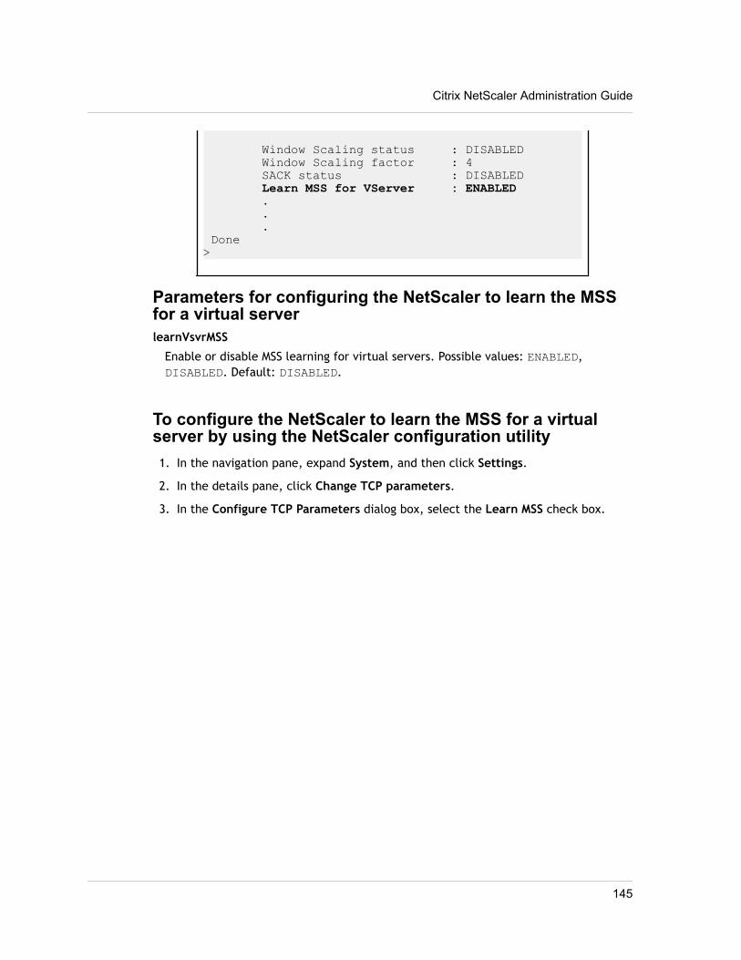
Window Scaling status : DISABLED Window Scaling factor : 4 SACK status : DISABLED Learn MSS for VServer : ENABLED . . . Done>
Parameters for configuring the NetScaler to learn the MSSfor a virtual serverlearnVsvrMSS
Enable or disable MSS learning for virtual servers. Possible values: ENABLED,DISABLED. Default: DISABLED.
To configure the NetScaler to learn the MSS for a virtualserver by using the NetScaler configuration utility1. In the navigation pane, expand System, and then click Settings.
2. In the details pane, click Change TCP parameters.
3. In the Configure TCP Parameters dialog box, select the Learn MSS check box.
Citrix NetScaler Administration Guide
145

Chapter 5 Advanced Configurations
146
Chapter 6
Web Interface
Topics:• How Web Interface Works
• Prerequisites
• Installing the Web Interface
• Configuring the Web Interface
The Web Interface on Citrix® NetScaler® appliances is basedon Java Server Pages (JSP) technology and provides access toCitrix® XenApp™ and Citrix® XenDesktop® applications. Usersaccess resources through a standard Web browser or by usingthe Citrix XenApp plug-in.
The Web Interface runs as a service on port 8080 on theNetScaler appliance. To create Web Interface sites, Java isexecuted on Apache Tomcat Web server version 6.0.26 on theNetScaler appliance. The Web Interface sites provide useraccess to the XenApp and XenDesktop resources, whichinclude applications, content, and desktops.
Note: This feature is supported only on NetScaler nCorebuilds.
The Web Interface installation includes installing the WebInterface tar file and JRE tar file on the NetScaler appliance.To configure the Web Interface, you create a Web Interfacesite and bind one or more XenApp or XenDesktop farms to it.
147
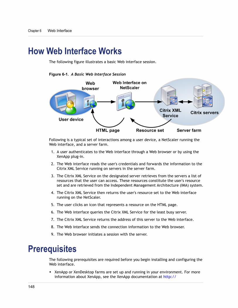
How Web Interface WorksThe following figure illustrates a basic Web interface session.
Figure 6-1. A Basic Web Interface Session
Following is a typical set of interactions among a user device, a NetScaler running theWeb interface, and a server farm.
1. A user authenticates to the Web interface through a Web browser or by using theXenApp plug-in.
2. The Web interface reads the user's credentials and forwards the information to theCitrix XML Service running on servers in the server farm.
3. The Citrix XML Service on the designated server retrieves from the servers a list ofresources that the user can access. These resources constitute the user's resourceset and are retrieved from the Independent Management Architecture (IMA) system.
4. The Citrix XML Service then returns the user's resource set to the Web interfacerunning on the NetScaler.
5. The user clicks an icon that represents a resource on the HTML page.
6. The Web interface queries the Citrix XML Service for the least busy server.
7. The Citrix XML Service returns the address of this server to the Web interface.
8. The Web interface sends the connection information to the Web browser.
9. The Web browser initiates a session with the server.
PrerequisitesThe following prerequisites are required before you begin installing and configuring theWeb interface.
w XenApp or XenDesktop farms are set up and running in your environment. For moreinformation about XenApp, see the XenApp documentation at http://
Chapter 6 Web Interface
148
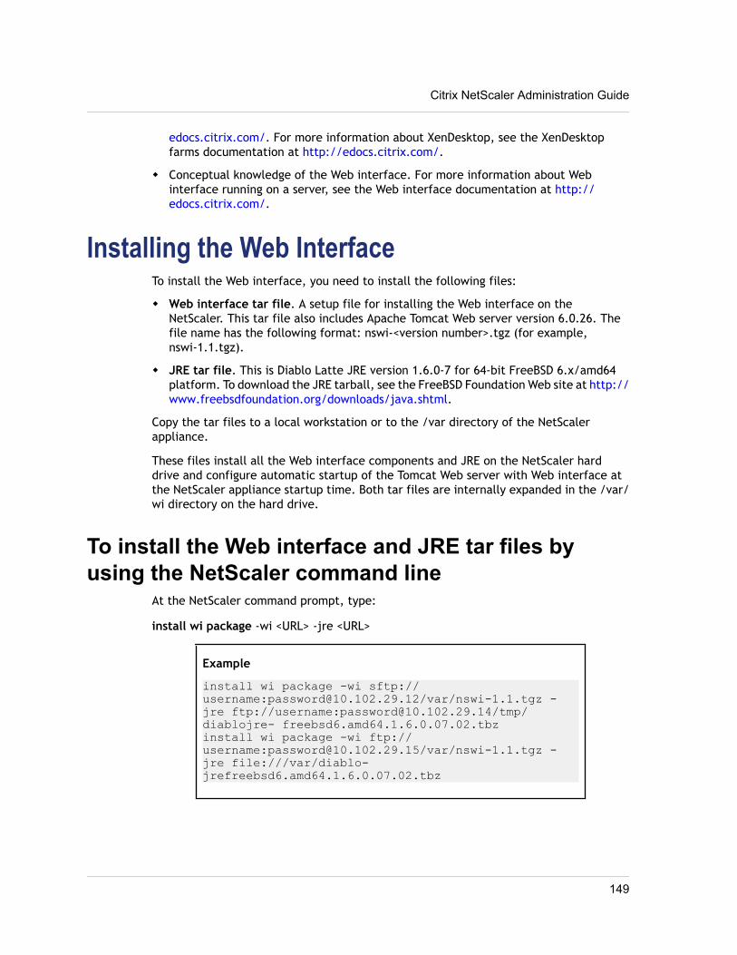
edocs.citrix.com/. For more information about XenDesktop, see the XenDesktopfarms documentation at http://edocs.citrix.com/.
w Conceptual knowledge of the Web interface. For more information about Webinterface running on a server, see the Web interface documentation at http://edocs.citrix.com/.
Installing the Web InterfaceTo install the Web interface, you need to install the following files:
w Web interface tar file. A setup file for installing the Web interface on theNetScaler. This tar file also includes Apache Tomcat Web server version 6.0.26. Thefile name has the following format: nswi-<version number>.tgz (for example,nswi-1.1.tgz).
w JRE tar file. This is Diablo Latte JRE version 1.6.0-7 for 64-bit FreeBSD 6.x/amd64platform. To download the JRE tarball, see the FreeBSD Foundation Web site at http://www.freebsdfoundation.org/downloads/java.shtml.
Copy the tar files to a local workstation or to the /var directory of the NetScalerappliance.
These files install all the Web interface components and JRE on the NetScaler harddrive and configure automatic startup of the Tomcat Web server with Web interface atthe NetScaler appliance startup time. Both tar files are internally expanded in the /var/wi directory on the hard drive.
To install the Web interface and JRE tar files byusing the NetScaler command line
At the NetScaler command prompt, type:
install wi package -wi <URL> -jre <URL>
Example
install wi package -wi sftp://username:[email protected]/var/nswi-1.1.tgz -jre ftp://username:[email protected]/tmp/diablojre- freebsd6.amd64.1.6.0.07.02.tbzinstall wi package -wi ftp://username:[email protected]/var/nswi-1.1.tgz -jre file:///var/diablo-jrefreebsd6.amd64.1.6.0.07.02.tbz
Citrix NetScaler Administration Guide
149
Parameters for installing the Web interface and JREtar files
Web Interface tar file pathComplete path to the Web interface tar file.
JRE tar file path
Complete path to the JRE tar file.
To install the Web interface and JRE tar files byusing the configuration utility
1. In the navigation pane, expand System, and then click Web Interface.
2. In the details pane, under Getting Started, click Install Web Interface.
3. In the Install Web Interface dialog box, in the Web Interface tar file path textbox, type the complete path to the Web interface tar file. You can also use thebrowse button to locate the file on your local system or the NetScaler hard drive.
4. In the JRE tar file path text box, type the complete path to the JRE tar file. Youcan also use the browse button to locate the file on your local system or theNetScaler hard drive.
5. Click Install.
Configuring the Web InterfaceTo configure the Web interface, you create a Web interface site and bind one or moreXenApp or XenDesktop farms to it. You then configure the Web interface to workbehind an HTTP or an HTTPS virtual server or Citrix Access Gateway™.
The following access methods are available for setting up Web interface sites:
w Direct Mode. You create an HTTP or an HTTPS virtual server on the NetScalerappliance and bind the Web interface service, running on port 8080 of the NetScalerappliance, to the virtual server. Clients on the LAN use the virtual server IP addressto access the Web interface. When using this access method, the URL format for theWeb interface site is as follows:
<HTTP or HTTPS>://<HTTP or HTTPS vserver IP address>:<vserverport number>/<Web Interface site path>
w Gateway Direct Mode. You associate the Web interface site with Access Gateway.Remote clients use the Access Gateway URL to access the Web interface site. Withthis access method, the URL format for the Web interface site is as follows:
Chapter 6 Web Interface
150
HTTPS://<Access Gateway URL>/<Web Interface site path>
Parameters for configuring Web interface sitesSite Path
Path to the Web interface site. This parameter is required. Type a site path or selectone of the following:w /Citrix/XenApp/w /Citrix/DesktopWeb/w /Citrix/PNAgent/
Site Type
Type of site. Possible values: XenApp/XenDesktop Web Site (configures the Webinterface site for access by a Web browser); XenApp/XenDesktop Services Site(configures the Web interface site for access by the XenApp plug-in). Default: XenApp/XenDesktop Web Site.
Published Resource Type
Method for accessing the published XenApp and XenDesktop resources. Possiblevalues: Online (allows applications to be launched on the XenApp and XenDesktopservers); Offline (allows streaming of applications to the client); DualMode (allowsboth modes). Default: Online.
Direct Mode
The Web interface is accessed through an HTTP or an HTTPS loopback load balancingvirtual server.
Virtual Server
Lists existing loopback load balancing virtual servers and an option to create a newone.
Protocol
The type of services to which the virtual server distributes requests. Possible values:HTTP, HTTPS. Default: HTTP.
IP Address
IP address of the virtual server. Can be an IPv4 or IPv6 address.
Port
Port on which the virtual server listens for client connections. Possible values: from 0through 65535.
Gateway Direct Mode
The Web interface is accessed through a configured Access Gateway.
Citrix NetScaler Administration Guide
151
Authentication Point
Authentication point to be used for the site. Possible values: Web interface,AccessGateway. Default: AccessGateway.
Access Gateway URL
URL of the Access Gateway.
Add DNS Entry
Specifies whether to add DNS address record to resolve the specified Access GatewayURL. Possible values: ON, OFF. Default: ON.
Trust SSL Certificate
Specifies whether the Web interface site trusts certificates signed by a non-trustedCA. Possible values: ON, OFF. Default: ON.
STA Server URL
URL of the Secure Ticket Authority (STA) server.
STA Server URL (2)
URL of the second STA server.
Session Reliability
Specifies whether to use session reliability through the Access Gateway. Possiblevalues: ON, OFF. Default: OFF.
Use Two STA Servers
Specifies whether the Web interface requests tickets from two separate gatewaySecure Ticket Authorities when a resource is accessed. Possible values: ON, OFF.Default: OFF.
Kiosk Mode
Specifies whether user settings should be persistent or last only for the lifetime ofthe session. When Kiosk mode is enabled, user settings do not persist from onesession to another. Possible values: ON, OFF. Default value: OFF.
Name
Name of a XenApp or XenDesktop farm. Any name can be used as a logicalrepresentation of a XenApp or XenDesktop farm. The name must not exceed 127characters.
XML Service Addresses
Comma-separated IP addresses or host names of either XenApp or XenDesktop serversproviding XML services.
Chapter 6 Web Interface
152
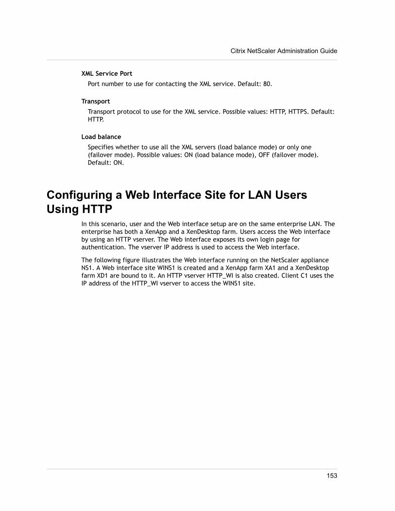
XML Service Port
Port number to use for contacting the XML service. Default: 80.
Transport
Transport protocol to use for the XML service. Possible values: HTTP, HTTPS. Default:HTTP.
Load balance
Specifies whether to use all the XML servers (load balance mode) or only one(failover mode). Possible values: ON (load balance mode), OFF (failover mode).Default: ON.
Configuring a Web Interface Site for LAN UsersUsing HTTP
In this scenario, user and the Web interface setup are on the same enterprise LAN. Theenterprise has both a XenApp and a XenDesktop farm. Users access the Web interfaceby using an HTTP vserver. The Web interface exposes its own login page forauthentication. The vserver IP address is used to access the Web interface.
The following figure illustrates the Web interface running on the NetScaler applianceNS1. A Web interface site WINS1 is created and a XenApp farm XA1 and a XenDesktopfarm XD1 are bound to it. An HTTP vserver HTTP_WI is also created. Client C1 uses theIP address of the HTTP_WI vserver to access the WINS1 site.
Citrix NetScaler Administration Guide
153
Figure 6-2. A Web Interface Site Configured for LAN Users Using HTTP
To configure a Web interface site for LAN users using HTTPby using the configuration utility1. In the navigation pane, expand System, and then click Web Interface.
2. In the details pane, click Web Interface Wizard.
3. On the wizard Introduction page, click Next.
4. On the wizard Configure Web Interface Site page, specify the values for thefollowing parameters, which correspond to parameters described in Parameters forconfiguring Web interface sites on page 151 as shown:
• Site Path* (You cannot change the name of an existing Web interface site.)
• Site Type
• Published Resource Type
• Kiosk Mode
* A required parameter.
5. Select Direct Mode and specify values for the following parameters, whichcorrespond to parameters described in Parameters for configuring Web interfacesites on page 151 as shown:
• Virtual Server
• Protocol (select HTTP)
Chapter 6 Web Interface
154
• IP Address
• Port
Note:When you create the HTTP vserver by using the configuration utility, theconfiguration utility automatically creates a service, which logically representsthe Web interface service running on the NetScaler appliance, and binds theservice to the HTTP virtual server.
For more information about services and virtual servers, see the Citrix NetScalerTraffic Management Guide at http://support.citrix.com/article/CTX128670.
6. Click Next.
7. On the wizard's Configure XenApp/XenDesktop Farm page, do one of the following:
• To add a XenApp or XenDesktop farm, click Add.
• To modify an existing XenApp or XenDesktop farm, select the farm, and thenclick Open.
8. In the Create XenApp/XenDesktop Farm or Configure XenApp/XenDesktop Farmdialog box, specify values for the following parameters, which correspond toparameters described in Parameters for configuring Web interface sites on page151 as shown:
• Name* (You cannot change the name of an existing XenApp or XenDesktop farm.)
• XML Service Addresses*
• XML Service Port
• Transport
• Load Balance
* A required parameter.
9. Click Next, and then click Finish.
10. Verify that the Web interface site you configured is correct by selecting the siteand viewing the Details section at the bottom of the pane. To view the Webinterface site, in the navigation pane, expand System, expand Web Interface, andthen click Sites.
To configure a Web interface site for LAN users using HTTPby using the command line1. Add a Web interface site. At the NetScaler command prompt, type:
add wi site <sitePath> -siteType ( XenAppWeb | XenAppServices )-publishedResourceType ( Online | Offline | DualMode ) -kioskMode ( ON | OFF)
Citrix NetScaler Administration Guide
155
Exampleadd wi site WINS1 -siteType XenAppWeb -publishedResourceType Online -kioskMode ON
2. Bind XenApp or XenDesktop farms to the Web interface site. At the NetScalercommand prompt, type:
bind wi site <sitePath> <farmName> <xmlServerAddresses> -xmlPort <value> -transport ( HTTP | HTTPS) -loadBalance ( ON | OFF )
Examplebind wi site WINS1 XA1 10.102.46.6 -xmlPort 80 -transport HTTP -LoadBalance OFFbind wi site WINS1 XD1 10.102.46.50 -xmlPort 80 -transport HTTP -LoadBalance OFF
3. Create a service that is a logical representation of the Web interface servicerunning on the NetScaler appliance. At the NetScaler command prompt, type:add service <name> <IP address> <serviceType> <port>Exampleadd service WI_Loopback_Service 127.0.0.1 HTTP 8080For more information, see the “Load Balancing” chapter of the Citrix NetScalerTraffic Management Guide at http://support.citrix.com/article/CTX128670.
4. Add an HTTP vserver. At the NetScaler command prompt, type:
add lb vserver <virtualServerName> <protocol> <IPAddress> <port>
Exampleadd lb vserver HTTP_WI HTTP 10.102.29.5 80For more information, see the “Load Balancing” chapter of the Citrix NetScalerTraffic Management Guide at http://support.citrix.com/article/CTX128670.
5. Bind the Web interface service to the HTTP vserver. At the NetScaler commandprompt, type:
bind lb vserver <virtualServerName> <serviceName>
Examplebind lb vserver HTTP_WI WI_Loopback_ServiceFor more information, see the “Load Balancing” chapter of the Citrix NetScalerTraffic Management Guide at http://support.citrix.com/article/CTX128670.
Configuring a Web Interface Site for LAN UsersUsing HTTPS
In this scenario, user accounts and the Web interface setup are on the same enterpriseLAN. Users access the Web interface by using an SSL-based (HTTPS) vserver. The Webinterface exposes its own login page for authentication. SSL offloading is done by thisvserver on the NetScaler. The vserver IP address is used to access the Web interfaceinstead of the NetScaler IP address (NSIP).
Chapter 6 Web Interface
156
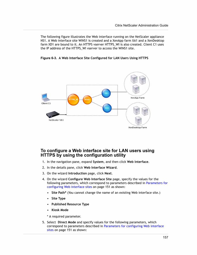
The following figure illustrates the Web interface running on the NetScaler applianceNS1. A Web interface site WINS1 is created and a XenApp farm XA1 and a XenDesktopfarm XD1 are bound to it. An HTTPS vserver HTTPS_WI is also created. Client C1 usesthe IP address of the HTTPS_WI vserver to access the WINS1 site.
Figure 6-3. A Web Interface Site Configured for LAN Users Using HTTPS
To configure a Web interface site for LAN users usingHTTPS by using the configuration utility1. In the navigation pane, expand System, and then click Web Interface.
2. In the details pane, click Web Interface Wizard.
3. On the wizard Introduction page, click Next.
4. On the wizard Configure Web Interface Site page, specify the values for thefollowing parameters, which correspond to parameters described in Parameters forconfiguring Web interface sites on page 151 as shown:
• Site Path* (You cannot change the name of an existing Web interface site.)
• Site Type
• Published Resource Type
• Kiosk Mode
* A required parameter.
5. Select Direct Mode and specify values for the following parameters, whichcorrespond to parameters described in Parameters for configuring Web interfacesites on page 151 as shown:
Citrix NetScaler Administration Guide
157
• Virtual Server
• Protocol (select HTTPS)
• IP Address
• Port
Note:When you create the HTTPS vserver by using the configuration utility, theconfiguration utility automatically creates a service, which logically representsthe Web interface service running on the NetScaler appliance, and binds theservice to the HTTPS virtual server.
For more information about services and virtual servers, see the Citrix NetScalerTraffic Management Guide at http://support.citrix.com/article/CTX128670.
6. Click Next.
7. On the wizard's Specify a server Certificate page, you create or specify anexisting SSL certificate–key pair. The SSL certificate–key pair is automaticallybound to the HTTPS vserver.
For more information, see “Binding an SSL Certificate Key Pair to the VirtualServer” in the “Secure Sockets Layer (SSL) Acceleration” chapter of the CitrixNetScaler Traffic Management Guide at http://support.citrix.com/article/CTX128670.
8. On the wizard's Configure XenApp/XenDesktop Farm page, do one of the following:
• To add a XenApp or XenDesktop farm, click Add.
• To modify an existing XenApp or XenDesktop farm, select the farm, and thenclick Open.
9. In the Create XenApp/XenDesktop Farm or Configure XenApp/XenDesktop Farmdialog box, specify values for the following parameters, which correspond toparameters described in Parameters for configuring Web interface sites on page151 as shown:
• Name* (You cannot change the name of an existing XenApp or XenDesktop farm.)
• XML Service Addresses*
• XML Service Port
• Transport
• Load Balance
* A required parameter.
10. Click Next, and then click Finish.
11. Verify that the Web interface site you configured is correct by selecting the siteand viewing the Details section at the bottom of the pane. To view the Web
Chapter 6 Web Interface
158
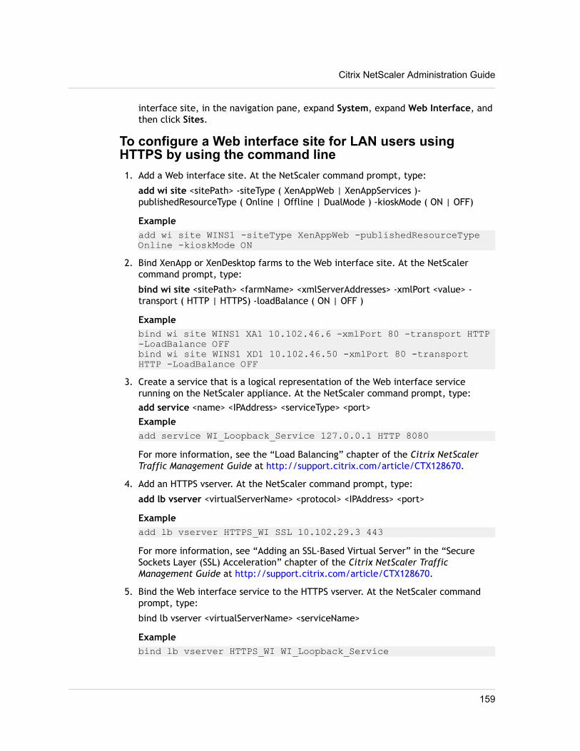
interface site, in the navigation pane, expand System, expand Web Interface, andthen click Sites.
To configure a Web interface site for LAN users usingHTTPS by using the command line1. Add a Web interface site. At the NetScaler command prompt, type:
add wi site <sitePath> -siteType ( XenAppWeb | XenAppServices )-publishedResourceType ( Online | Offline | DualMode ) -kioskMode ( ON | OFF)
Exampleadd wi site WINS1 -siteType XenAppWeb -publishedResourceType Online -kioskMode ON
2. Bind XenApp or XenDesktop farms to the Web interface site. At the NetScalercommand prompt, type:
bind wi site <sitePath> <farmName> <xmlServerAddresses> -xmlPort <value> -transport ( HTTP | HTTPS) -loadBalance ( ON | OFF )
Examplebind wi site WINS1 XA1 10.102.46.6 -xmlPort 80 -transport HTTP -LoadBalance OFFbind wi site WINS1 XD1 10.102.46.50 -xmlPort 80 -transport HTTP -LoadBalance OFF
3. Create a service that is a logical representation of the Web interface servicerunning on the NetScaler appliance. At the NetScaler command prompt, type:add service <name> <IPAddress> <serviceType> <port>Exampleadd service WI_Loopback_Service 127.0.0.1 HTTP 8080For more information, see the “Load Balancing” chapter of the Citrix NetScalerTraffic Management Guide at http://support.citrix.com/article/CTX128670.
4. Add an HTTPS vserver. At the NetScaler command prompt, type:
add lb vserver <virtualServerName> <protocol> <IPAddress> <port>
Exampleadd lb vserver HTTPS_WI SSL 10.102.29.3 443For more information, see “Adding an SSL-Based Virtual Server” in the “SecureSockets Layer (SSL) Acceleration” chapter of the Citrix NetScaler TrafficManagement Guide at http://support.citrix.com/article/CTX128670.
5. Bind the Web interface service to the HTTPS vserver. At the NetScaler commandprompt, type:
bind lb vserver <virtualServerName> <serviceName>
Examplebind lb vserver HTTPS_WI WI_Loopback_Service
Citrix NetScaler Administration Guide
159
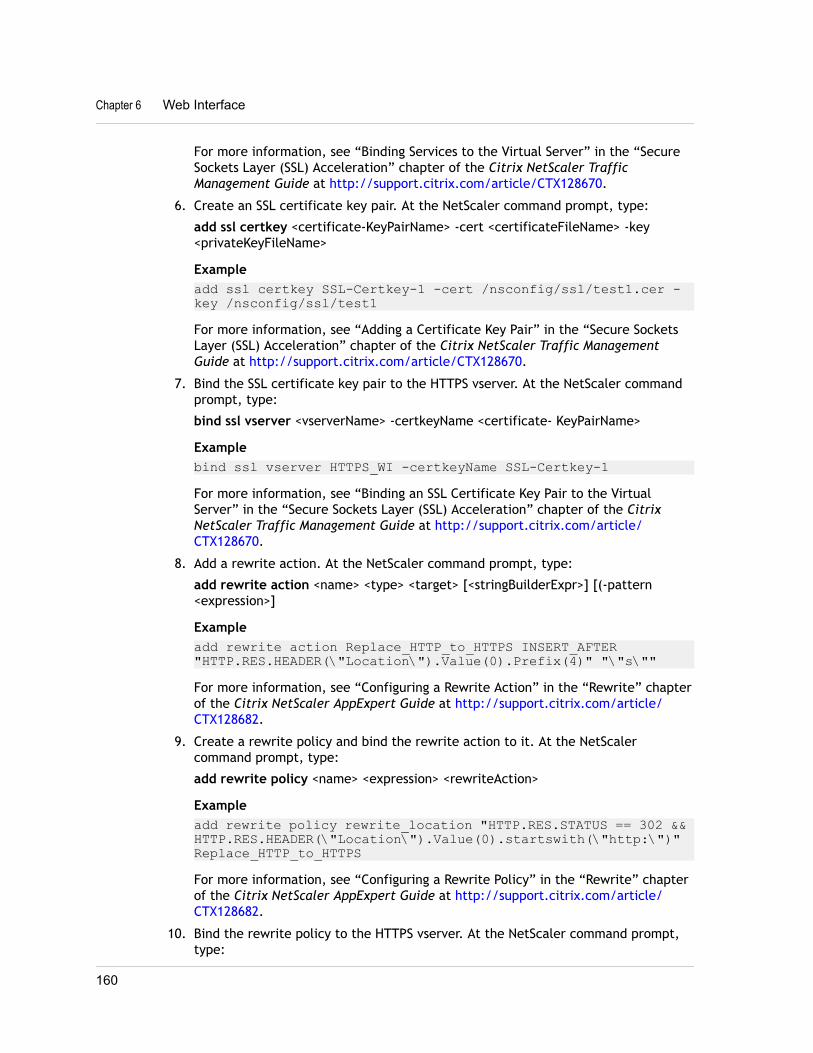
For more information, see “Binding Services to the Virtual Server” in the “SecureSockets Layer (SSL) Acceleration” chapter of the Citrix NetScaler TrafficManagement Guide at http://support.citrix.com/article/CTX128670.
6. Create an SSL certificate key pair. At the NetScaler command prompt, type:
add ssl certkey <certificate-KeyPairName> -cert <certificateFileName> -key<privateKeyFileName>
Exampleadd ssl certkey SSL-Certkey-1 -cert /nsconfig/ssl/test1.cer -key /nsconfig/ssl/test1For more information, see “Adding a Certificate Key Pair” in the “Secure SocketsLayer (SSL) Acceleration” chapter of the Citrix NetScaler Traffic ManagementGuide at http://support.citrix.com/article/CTX128670.
7. Bind the SSL certificate key pair to the HTTPS vserver. At the NetScaler commandprompt, type:
bind ssl vserver <vserverName> -certkeyName <certificate- KeyPairName>
Examplebind ssl vserver HTTPS_WI -certkeyName SSL-Certkey-1For more information, see “Binding an SSL Certificate Key Pair to the VirtualServer” in the “Secure Sockets Layer (SSL) Acceleration” chapter of the CitrixNetScaler Traffic Management Guide at http://support.citrix.com/article/CTX128670.
8. Add a rewrite action. At the NetScaler command prompt, type:
add rewrite action <name> <type> <target> [<stringBuilderExpr>] [(-pattern<expression>]
Exampleadd rewrite action Replace_HTTP_to_HTTPS INSERT_AFTER "HTTP.RES.HEADER(\"Location\").Value(0).Prefix(4)" "\"s\""For more information, see “Configuring a Rewrite Action” in the “Rewrite” chapterof the Citrix NetScaler AppExpert Guide at http://support.citrix.com/article/CTX128682.
9. Create a rewrite policy and bind the rewrite action to it. At the NetScalercommand prompt, type:
add rewrite policy <name> <expression> <rewriteAction>
Exampleadd rewrite policy rewrite_location "HTTP.RES.STATUS == 302 && HTTP.RES.HEADER(\"Location\").Value(0).startswith(\"http:\")" Replace_HTTP_to_HTTPSFor more information, see “Configuring a Rewrite Policy” in the “Rewrite” chapterof the Citrix NetScaler AppExpert Guide at http://support.citrix.com/article/CTX128682.
10. Bind the rewrite policy to the HTTPS vserver. At the NetScaler command prompt,type:
Chapter 6 Web Interface
160
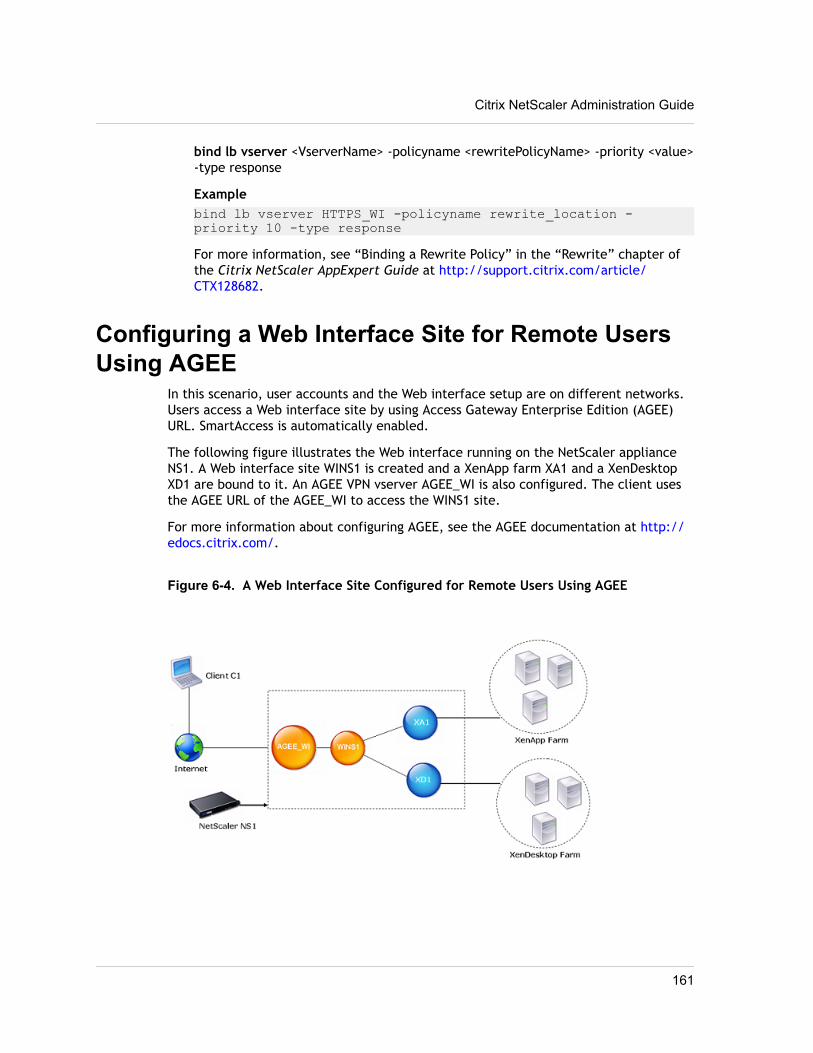
bind lb vserver <VserverName> -policyname <rewritePolicyName> -priority <value>-type response
Examplebind lb vserver HTTPS_WI -policyname rewrite_location -priority 10 -type responseFor more information, see “Binding a Rewrite Policy” in the “Rewrite” chapter ofthe Citrix NetScaler AppExpert Guide at http://support.citrix.com/article/CTX128682.
Configuring a Web Interface Site for Remote UsersUsing AGEE
In this scenario, user accounts and the Web interface setup are on different networks.Users access a Web interface site by using Access Gateway Enterprise Edition (AGEE)URL. SmartAccess is automatically enabled.
The following figure illustrates the Web interface running on the NetScaler applianceNS1. A Web interface site WINS1 is created and a XenApp farm XA1 and a XenDesktopXD1 are bound to it. An AGEE VPN vserver AGEE_WI is also configured. The client usesthe AGEE URL of the AGEE_WI to access the WINS1 site.
For more information about configuring AGEE, see the AGEE documentation at http://edocs.citrix.com/.
Figure 6-4. A Web Interface Site Configured for Remote Users Using AGEE
Citrix NetScaler Administration Guide
161
To configure a Web interface site for remote users usingAGEE by using the configuration utility1. In the navigation pane, expand System, and then click Web Interface.
2. In the details pane, click Web Interface Wizard.
3. On the wizard Introduction page, click Next.
4. On the wizard Configure Web Interface Site page, specify the values for thefollowing parameters, which correspond to parameters described in Parameters forconfiguring Web interface sites on page 151 as shown:
• Site Path* (You cannot change the name of an existing Web interface site.)
• Site Type
• Published Resource Type
• Kiosk Mode
* A required parameter.
5. Select Gateway Direct Mode and specify values for the following parameters,which correspond to parameters described in Parameters for configuring Webinterface sites on page 151 as shown:
• Authentication Point
• Access Gateway URL
• Add DNS Entry
• Trust SSL Certificate
• STA Server URL
• STA Server URL (2)
• Session Reliability
• Use two STA Servers
6. Click Next.
7. On the wizard's Configure XenApp/XenDesktop Farm page, do one of the following:
• To add a XenApp or XenDesktop farm, click Add.
• To modify an existing XenApp or XenDesktop farm, select the farm, and thenclick Open.
8. In the Create XenApp/XenDesktop Farm or Configure XenApp/XenDesktop Farmdialog box, specify values for the following parameters, which correspond toparameters described in Parameters for configuring Web interface sites on page151 as shown:
• Name* (You cannot change the name of an existing XenApp or XenDesktop farm.)
• XML Service Addresses*
Chapter 6 Web Interface
162
• XML Service Port
• Transport
• Load Balance
* A required parameter.
9. Click Next, and then click Finish.
10. Verify that the Web interface site you configured is correct by selecting the siteand viewing the Details section at the bottom of the pane. To view the Webinterface site, in the navigation pane, expand System, expand Web Interface, andthen click Sites.
To configure a Web interface site for remote users usingAGEE by using the command line1. Add a Web interface site. At the NetScaler command prompt, type:
add wi site <sitePath> <agURL> <staURL> -sessionReliability ( ON | OFF ) -useTwoTickets ( ON | OFF ) -secondSTAURL <string> -authenticationPoint( WebInterface | AccessGateway ) -siteType ( XenAppWeb | XenAppServices ) -publishedResourceType ( Online | Offline | DualMode ) -kioskMode ( ON | OFF )
Exampleadd wi site WINS1 https://ag.mycompany.com http://ag.staserver.com -sessionReliability OFF -authenticationPoint AccessGateway -siteType XenAppWeb -publishedResourceType Online -kioskMode ON
2. Bind XenApp or XenDesktop farms to the Web interface site. At the NetScalercommand prompt, type:
bind wi site <sitePath> <farmName> <xmlServerAddresses> -xmlPort <value> -transport ( HTTP | HTTPS) -loadBalance ( ON | OFF )
Examplebind wi site WINS1 XA1 10.102.46.6 -xmlPort 80 -transport HTTP -LoadBalance OFFbind wi site WINS1 XD1 10.102.46.50 -xmlPort 80 -transport HTTP -LoadBalance OFF
Citrix NetScaler Administration Guide
163

Chapter 6 Web Interface
164
Chapter 7
Enhanced Application Visibility UsingAppFlow
Topics:• How AppFlow Works
• Configuring the AppFlowFeature
The Citrix® NetScaler® appliance is a central point of controlfor all application traffic in the data center. It collects flowand user-session level information valuable for applicationperformance monitoring, analytics, and business intelligenceapplications. AppFlow transmits the information by using theInternet Protocol Flow Information eXport (IPFIX) format,which is an open Internet Engineering Task Force (IETF)standard defined in RFC 5101. IPFIX (the standardized versionof Cisco's NetFlow) is widely used to monitor network flowinformation. AppFlow defines new Information Elements torepresent application-level information.
Using UDP as the transport protocol, AppFlow transmits thecollected data, called flow records, to one or more IPv4collectors. The collectors aggregate the flow records andgenerate real-time or historical reports.
AppFlow provides visibility at the transaction level for HTTP,SSL, TCP, and SSL_TCP flows. You can sample and filter theflow types that you want to monitor.
AppFlow use actions and policies to send records for aselected flow to specific set of collectors. An AppFlow actionspecifies which set of collectors will receive the AppFlowrecords. Policies, which are based on Advanced expressionscan be configured to select flows for which flow records willbe sent to the collectors specified by the associated AppFlowaction.
To limit the types of flows, you can enable AppFlow for avirtual server. AppFlow can also provide statistics for thevirtual server.
You can also enable AppFlow for a specific service,representing an application server, and monitor the traffic tothat application server.
Note: This feature is supported only on NetScaler nCorebuilds.
165
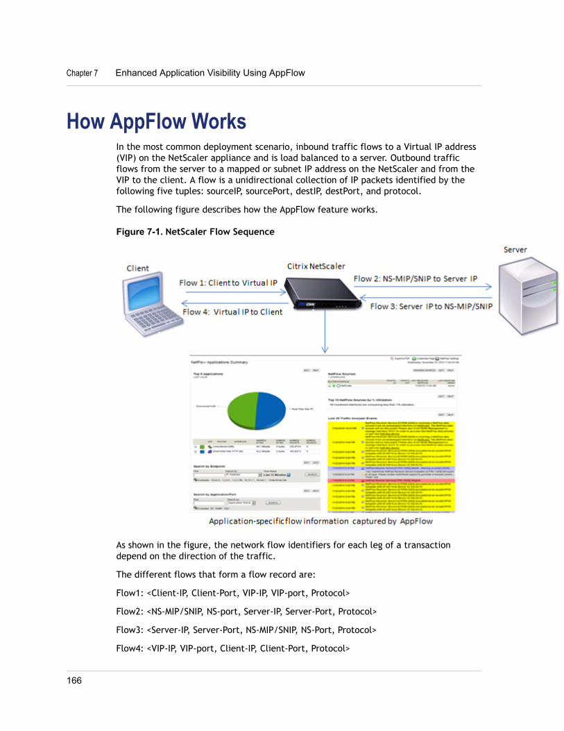
How AppFlow WorksIn the most common deployment scenario, inbound traffic flows to a Virtual IP address(VIP) on the NetScaler appliance and is load balanced to a server. Outbound trafficflows from the server to a mapped or subnet IP address on the NetScaler and from theVIP to the client. A flow is a unidirectional collection of IP packets identified by thefollowing five tuples: sourceIP, sourcePort, destIP, destPort, and protocol.
The following figure describes how the AppFlow feature works.
Figure 7-1. NetScaler Flow Sequence
As shown in the figure, the network flow identifiers for each leg of a transactiondepend on the direction of the traffic.
The different flows that form a flow record are:
Flow1: <Client-IP, Client-Port, VIP-IP, VIP-port, Protocol>
Flow2: <NS-MIP/SNIP, NS-port, Server-IP, Server-Port, Protocol>
Flow3: <Server-IP, Server-Port, NS-MIP/SNIP, NS-Port, Protocol>
Flow4: <VIP-IP, VIP-port, Client-IP, Client-Port, Protocol>
Chapter 7 Enhanced Application Visibility Using AppFlow
166
To help the collector link all four flows in a transaction, AppFlow adds a customtransactionID element to each flow. For application-level content switching, such asHTTP, it is possible for a single client TCP connection to be load balanced to differentbackend TCP connections for each request. AppFlow provides a set of records for eachtransaction.
Flow RecordsAppFlow records contain standard NetFlow or IPFIX information, such as time stampsfor the beginning and end of a flow, packet count, and byte count. AppFlow recordsalso contain application-level information (such as HTTP URLs, HTTP request methodsand response status codes, server response time, and latency). IPFIX flow records arebased on templates that need to be sent before sending flow records.
TemplatesAppFlow defines a set of templates, one for each type of flow. Each template containsa set of standard Information Elements (IEs) and Enterprise-specific InformationElements (EIEs). IPFIX templates define the order and sizes of the Information Elements(IE) in the flow record. The templates are sent to the collectors at regular intervals, asdescribed in RFC 5101.
A template can include the following EIEs:
transactionIDAn unsigned 32-bit number identifying an application-level transaction. For HTTP,this corresponds to a request and response pair. All flow records that correspond tothis request and response pair have the same transaction ID. In the most commoncase, there are four uniflow records that correspond to this transaction. If theNetScaler generates the response by itself (served from the integrated cache or by asecurity policy), there may be only two flow records for this transaction.
connectionIDAn unsigned 32-bit number identifying a layer-4 connection (TCP or UDP). TheNetScaler flows are usually bidirectional, with two separate flow records for eachdirection of the flow. This information element can be used to link the two flows.
For the NetScaler, connectionID is an identifier for the connection data structure totrack the progress of a connection. In an HTTP transaction, for instance, a givenconnectionID may have multiple transactionID elements corresponding to multiplerequests that were made on that connection.
tcpRTTThe round trip time, in milliseconds, as measured on the TCP connection. This can beused as a metric to determine the client or server latency on the network.
httpRequestMethodAn 8-bit number indicating the HTTP method used in the transaction. An optionstemplate with the number-to-method mapping is sent along with the template.
Citrix NetScaler Administration Guide
167
httpRequestSizeAn unsigned 32-bit number indicating the request payload size.
httpRequestURLThe HTTP URL requested by the client.
httpUserAgentThe source of incoming requests to the Web server.
httpResponseStatusAn unsigned 32-bit number indicating the response status code.
httpResponseSizeAn unsigned 32-bit number indicating the response size.
httpResponseTimeToFirstByteAn unsigned 32-bit number indicating the time taken to receive the first byte of theresponse.
httpResponseTimeToLastByteAn unsigned 32-bit number indicating the time taken to receive the last byte of theresponse.
flowFlagsAn unsigned 64-bit flag used to indicate different flow conditions.
Configuring the AppFlow FeatureYou configure AppFlow in the same manner as most other policy-based features. First,you enable the AppFlow feature. Then you specify the collectors to which the flowrecords are sent. After that, you define actions, which are sets of configred collectors.Then you configure one or more policies and associate a action to each policy. Thepolicy tells the NetScaler appliance to select requests the flow records of which aresent to the associated action. Finally, you bind each policy either globally or to aspecific vservers to put it into effect.
You can further set AppFlow parameters to specify the template refresh interval and toenable the exporting of httpURL, httpCookie, and httpReferer information. On eachcollector, you must specify the NetScaler IP address as the address of the exporter.
Note: For information about configuring the NetScaler as an exporter on the collector,see the documentation for the specific collector.
The configuration utility provides tools that help users define the policies and actionsthat determine exactly how the NetScaler appliance export records for a particularflow to a set of collectors(action.) The NetScaler command line provides acorresponding set of CLI-based commands for experienced users who prefer a commandline.
Chapter 7 Enhanced Application Visibility Using AppFlow
168
Enabling or Disabling the AppFlow FeatureTo be able to use the AppFlow feature, you must first enable it.
To enable or disable the AppFlow feature by using theNetScaler command lineAt the NetScaler command prompt, type one of the following commands:
w enable ns feature appflow
w disable ns feature appflow
To enable the AppFlow feature by using the configurationutility1. In the navigation pane, expand System, and then click Settings.
2. In the details pane, under Modes and Features, click Configure advancedfeatures.
3. In the Configure Advanced Features dialog box, select the AppFlow check box,and then click OK.
4. In the Enable/Disable Feature(s)? dialog box, click Yes.
Specifying a CollectorA collector receives flow records generated by the NetScaler appliance. To be able tosend flow records, you must specify at least one collector. You can specify up to four.However, you cannot export the same data to multiple collectors. You can removeunused collectors.
To specify a collector by using the NetScaler command lineAt the NetScaler command prompt, type the following commands to add a collectorand verify the configuration:
w add appflowCollector <name> -IPAddress <ipaddress> -port <port_number>
w show appflowCollector <name>
Example> add appflowCollector coll1 -IPAddress 10.102.29.251 -port 8000Done
> show appflowCollector coll1
1)Collector name: coll1 Collector IPv4 address: 10.102.29.251 Collector UDP port: 8000
Citrix NetScaler Administration Guide
169
To remove a collector by using the NetScaler command lineAt the NetScaler command prompt, type:
rm appflowCollector <name>
Parameters for specifying a collectorname
Name of the collector to which to export data. Maximum characters: 255.
ipaddressThe IPv4 address of the collector.
portThe UDP port on which the collector is listening. Default port: 4739.
To specify a collector by using the configuration utility1. In the navigation pane, expand AppFlow, and then click Collectors.
2. In the details pane, click Add.
3. In the Create AppFlow Collector dialog box, specify values for the followingparameters, which correspond to parameters described in "Parameters forspecifying a collector" as shown:
• Name*—name (cannot be changed for an existing collector)
• IP Address*—ipaddress (cannot be changed for an existing collector)
• Port—port (cannot be changed for an existing collector)
*A required parameter
4. To remove a collector from the list, select the collector, and then click Remove.
5. Click Create, and then click Close.
Configuring an AppFlow ActionAn Appflow action is a set collectors, to which the flow records are sent if theassociated Apflow policy matches.
To configure an AppFlow action by using the NetScalercommand lineAt the NetScaler command prompt, type the following commands to configure anAppflow action and verify the configuration:
w add appflow action <name> --collectors <string> ... [-comment <string>]
w show appflow action
Chapter 7 Enhanced Application Visibility Using AppFlow
170
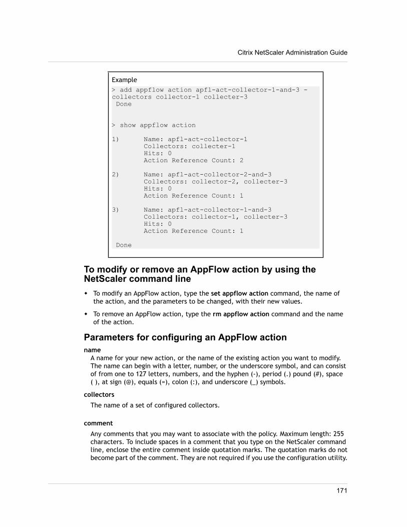
Example> add appflow action apfl-act-collector-1-and-3 -collectors collector-1 collecter-3 Done
> show appflow action
1) Name: apfl-act-collector-1 Collectors: collecter-1 Hits: 0 Action Reference Count: 2
2) Name: apfl-act-collector-2-and-3 Collectors: collector-2, collecter-3 Hits: 0 Action Reference Count: 1
3) Name: apfl-act-collector-1-and-3 Collectors: collector-1, collecter-3 Hits: 0 Action Reference Count: 1
Done
To modify or remove an AppFlow action by using theNetScaler command linew To modify an AppFlow action, type the set appflow action command, the name of
the action, and the parameters to be changed, with their new values.
w To remove an AppFlow action, type the rm appflow action command and the nameof the action.
Parameters for configuring an AppFlow actionname
A name for your new action, or the name of the existing action you want to modify.The name can begin with a letter, number, or the underscore symbol, and can consistof from one to 127 letters, numbers, and the hyphen (-), period (.) pound (#), space( ), at sign (@), equals (=), colon (:), and underscore (_) symbols.
collectors
The name of a set of configured collectors.
comment
Any comments that you may want to associate with the policy. Maximum length: 255characters. To include spaces in a comment that you type on the NetScaler commandline, enclose the entire comment inside quotation marks. The quotation marks do notbecome part of the comment. They are not required if you use the configuration utility.
Citrix NetScaler Administration Guide
171
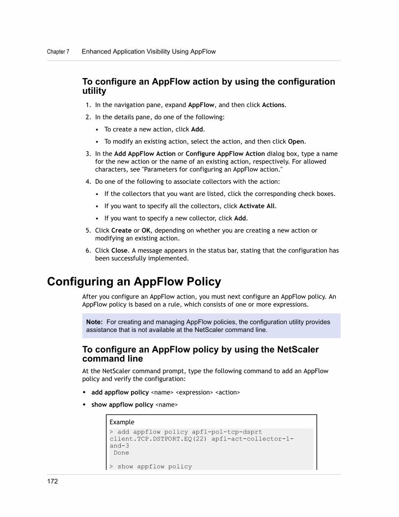
To configure an AppFlow action by using the configurationutility1. In the navigation pane, expand AppFlow, and then click Actions.
2. In the details pane, do one of the following:
• To create a new action, click Add.
• To modify an existing action, select the action, and then click Open.
3. In the Add AppFlow Action or Configure AppFlow Action dialog box, type a namefor the new action or the name of an existing action, respectively. For allowedcharacters, see "Parameters for configuring an AppFlow action."
4. Do one of the following to associate collectors with the action:
• If the collectors that you want are listed, click the corresponding check boxes.
• If you want to specify all the collectors, click Activate All.
• If you want to specify a new collector, click Add.
5. Click Create or OK, depending on whether you are creating a new action ormodifying an existing action.
6. Click Close. A message appears in the status bar, stating that the configuration hasbeen successfully implemented.
Configuring an AppFlow PolicyAfter you configure an AppFlow action, you must next configure an AppFlow policy. AnAppFlow policy is based on a rule, which consists of one or more expressions.
Note: For creating and managing AppFlow policies, the configuration utility providesassistance that is not available at the NetScaler command line.
To configure an AppFlow policy by using the NetScalercommand lineAt the NetScaler command prompt, type the following command to add an AppFlowpolicy and verify the configuration:
w add appflow policy <name> <expression> <action>
w show appflow policy <name>
Example> add appflow policy apfl-pol-tcp-dsprt client.TCP.DSTPORT.EQ(22) apfl-act-collector-1-and-3 Done
> show appflow policy
Chapter 7 Enhanced Application Visibility Using AppFlow
172
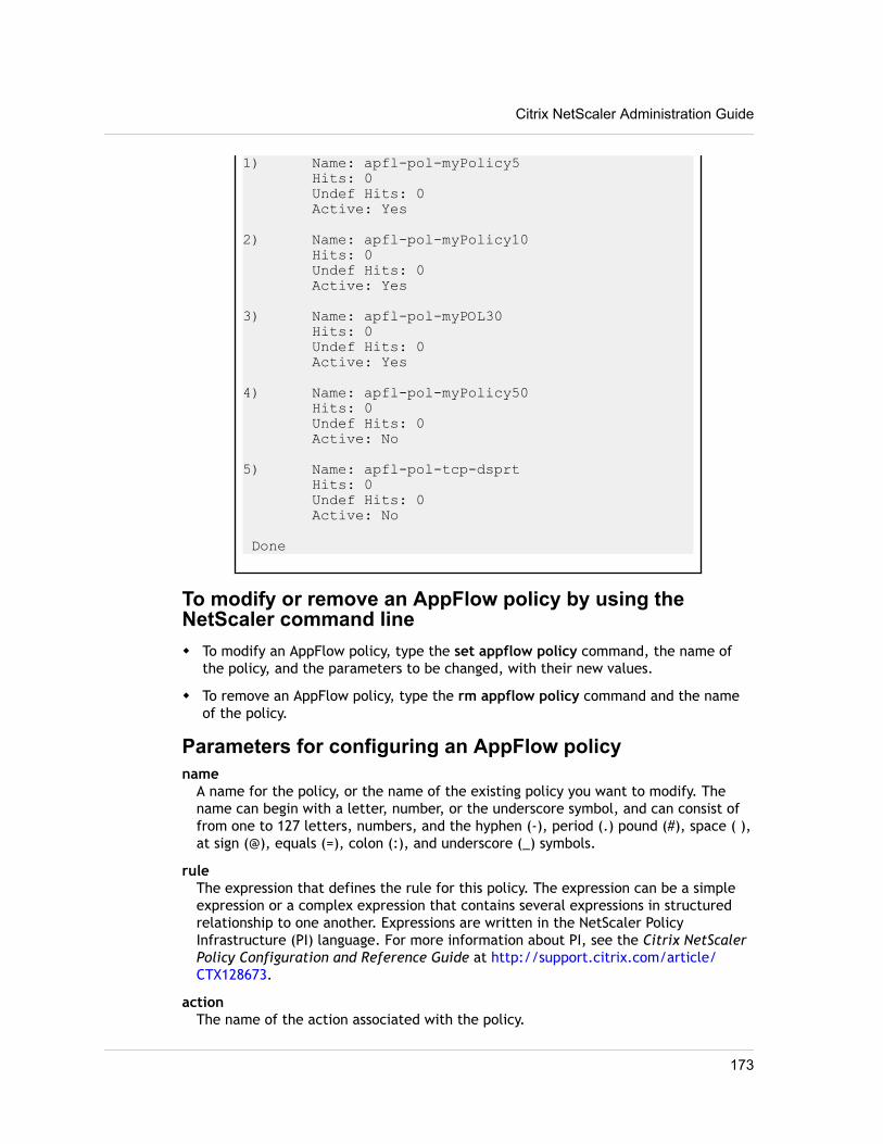
1) Name: apfl-pol-myPolicy5 Hits: 0 Undef Hits: 0 Active: Yes
2) Name: apfl-pol-myPolicy10 Hits: 0 Undef Hits: 0 Active: Yes
3) Name: apfl-pol-myPOL30 Hits: 0 Undef Hits: 0 Active: Yes
4) Name: apfl-pol-myPolicy50 Hits: 0 Undef Hits: 0 Active: No
5) Name: apfl-pol-tcp-dsprt Hits: 0 Undef Hits: 0 Active: No
Done
To modify or remove an AppFlow policy by using theNetScaler command linew To modify an AppFlow policy, type the set appflow policy command, the name of
the policy, and the parameters to be changed, with their new values.
w To remove an AppFlow policy, type the rm appflow policy command and the nameof the policy.
Parameters for configuring an AppFlow policyname
A name for the policy, or the name of the existing policy you want to modify. Thename can begin with a letter, number, or the underscore symbol, and can consist offrom one to 127 letters, numbers, and the hyphen (-), period (.) pound (#), space ( ),at sign (@), equals (=), colon (:), and underscore (_) symbols.
ruleThe expression that defines the rule for this policy. The expression can be a simpleexpression or a complex expression that contains several expressions in structuredrelationship to one another. Expressions are written in the NetScaler PolicyInfrastructure (PI) language. For more information about PI, see the Citrix NetScalerPolicy Configuration and Reference Guide at http://support.citrix.com/article/CTX128673.
actionThe name of the action associated with the policy.
Citrix NetScaler Administration Guide
173
comment
Any comments that you may want to associate with the policy. Maximum length: 255characters. To include spaces in a comment that you type on the NetScaler commandline, enclose the entire comment inside quotation marks. The quotation marks do notbecome part of the comment. They are not required if you use the configuration utility.
To configure an AppFlow policy by using the configurationutility1. In the navigation pane, expand AppFlow, and then click Policies.
2. In the details pane, do one of the following:
• To create a new policy, click Add.
• To modify an existing policy, select the policy, and then click Open.
3. In the Create AppFlow Policy or Configure AppFlow Policy dialog box, type orselect values for the following parameters, which correspond to parametersdescribed in "Parameters for configuring an AppFlow policy" as shown:
• Name*—name
• Action*—action
• Expression*—rule (You can add the expression in any of three ways. (1) You canclick Add and choose an existing expression in the Frequently Used Expressionsdrop-down list. (2) You can type the expression directly into the supplied textbox. For brief help and prompts, while the cursor is in the text box, hold downthe CTRL key while you press the Space bar. (3) You can use the Add Expressiondialog box, as described in “To add an expression by using the Add Expressiondialog box .”)
• Comments—comment
4. Click Create or OK, depending on whether you are creating a new policy ormodifying an existing policy.
5. Click Close. A message appears in the status bar, stating that the configuration hasbeen successfully implemented.
To add an expression by using the Add Expression dialogbox1. In the Add Expression dialog box, in the first list box choose the first term for your
expression.HTTP
The HTTP protocol. Choose this if you want to examine some aspect of therequest that pertains to the HTTP protocol.
SYSThe protected Web site(s). Choose this if you want to examine some aspect ofthe request that pertains to the recipient of the request.
Chapter 7 Enhanced Application Visibility Using AppFlow
174
CLIENTThe computer that sent the request. Choose this if you want to examine someaspect of the sender of the request.
When you make your choice, the rightmost list box lists appropriate terms for thenext part of your expression.
2. In the second list box, choose the second term for your expression.The choices depend upon which choice you made in the previous step, and areappropriate to the context. After you make your second choice, the Help windowbelow the Construct Expression window (which was blank) displays helpdescribing the purpose and use of the term you just chose.
3. Continue choosing terms from the list boxes that appear to the right of theprevious list box, or typing strings or numbers in the text boxes that appear toprompt you to enter a value, until your expression is finished. For moreinformation about the PI expressions language and creating expressions forAppFlow policies, see the Citrix NetScaler Policy Configuration and ReferenceGuide at http://support.citrix.com/article/CTX128673.
Binding an AppFlow PolicyTo put a policy into effect, you must bind it either globally, so that it applies to alltraffic that flows through the NetScaler, or to a specific virtual server, so that thepolicy applies only to the traffic related to that virtual server.
When you bind a policy, you assign it a priority. The priority determines the order inwhich the policies you define are evaluated. You can set the priority to any positiveinteger.
In the NetScaler operating system, policy priorities work in reverse order—the higherthe number, the lower the priority. For example, if you have three policies withpriorities of 10, 100, and 1000, the policy assigned a priority of 10 is performed first,then the policy assigned a priority of 100, and finally the policy assigned an order of 1000.
You can leave yourself plenty of room to add other policies in any order, and still setthem to evaluate in the order you want, by setting priorities with intervals of 50 or 100between each policy when you globally bind it. You can then add additional policies atany time without having to change the priority of an existing policy.
For additional information about binding policies on the NetScaler, see the CitrixNetScaler Traffic Management Guide at http://support.citrix.com/article/CTX128670.
To globally bind an AppFlow policy by using the NetScalercommand lineAt the NetScaler command prompt, type the following command to globally bind anAppFlow policy and verify the configuration:
w bind appflow global <policyName> <priority> [<gotoPriorityExpression [-type<type>] [-invoke (<labelType> <labelName>)]
w show appflow global
Citrix NetScaler Administration Guide
175
To bind an AppFlow policy to a specific virtual server byusing the NetScaler command lineAt the NetScaler command prompt, type the following command to bind an appflowpolicy to a specific virtual server and verify the configuration:
bind lb vserver <name> -policyname <policy_name> -priority <priority>
Parameters for binding an AppFlow policyname
The name of the virtual server to which you are binding the AppFlow policy.
policynameThe name of the AppFlow policy that you want to bind.
priorityA number specifying the priority assigned to this policy. The lower the number, thehighter the priority. The priority determines the order in which policies areevaluated, allowing the NetScaler to evaluate the most specific policy first, andmore general policies in descending order, finishing with the most general policy.
gotoPriorityExpressionThe priority of the next policy that should be evaluated if this policy matches. If setto END, this parameter halts the policy evaluation process after evaluation of thecurrent policy. If you are careful to assign your policy priorities in the right order, youcan use this parameter to skip over policies in the event that the current policymatches, and go directly to a specific policy.
typeBind point, specifying where to bind the policy.
invokeInvoke flag.
labelTypeType of policy label invocation.
labelName
Name of the label to invoke if the current policy rule evaluates to TRUE.
To globally bind an AppFlow policy by using theconfiguration utility1. In the navigation pane, expand AppFlow.
2. On the AppFlow page, click Policy Manager.
3. In the AppFlow Policy Manager dialog box, in the Bind Points menu, selectDefault Global.
4. Click Insert Policy to insert a new row and display a drop-down list of all unboundAppFlow policies.
Chapter 7 Enhanced Application Visibility Using AppFlow
176
5. Click one of the policies on the list. That policy is inserted into the list of globallybound AppFlow policies.
6. Click Apply Changes.
7. Click Close. A message appears in the status bar, stating that the configuration hasbeen successfully implemented.
To bind an AppFlow policy to a specific virtual server byusing the configuration utility1. In the navigation pane, expand Load Balancing, and then click Virtual Servers.
2. On the Load Balancing Virtual Servers page, select the virtual server to which youwant to bind the AppFlow policy, and then click Open.
3. In the Configure Virtual Server (Load Balancing) dialog box, select the Policiestab to display the policies bound to that particular virtual server..
4. Click Insert Policy to insert a new row and display a drop-down list of all unboundAppFlow policies.
5. From the drop-down list that appears under Policy Name, select the policy thatyou want to bind to this virtual server.
6. Click OK, and then click Close. A message appears in the status bar, stating thatthe configuration has been successfully implemented
Enabling AppFlow for Virtual ServersIf you want to monitor only the traffic through certain virtual servers, enable AppFlowspecifically for those virtual servers. You can enable AppFlow for load balancing,content switching, cache redirection, SSL VPN, GSLB, and authentication virtual servers.
To enable AppFlow for a virtual server by using theNetScaler command lineAt the NetScaler command prompt, type:
set <feature_name> vserver <vServerName> <protocol> <IPAddress> <port> -appflowLog ENABLED
Exampleset cs vserver Vserver-CS-1 HTTP 10.102.29.161 80 -appflowLog ENABLED
To enable AppFlow for a virtual server by using theconfiguration utility1. In the navigation pane, expand the feature node for which you want to enable
AppFlow, and then click Virtual Servers.
Citrix NetScaler Administration Guide
177
For example, expand Content Switching to enable AppFlow for a content switchingvirtual server, and then click Virtual Servers.
2. In the details pane, do one of the following:
• To enable AppFlow for a new virtual server, click Add.
• To enable AppFlow for an existing virtual server, select the virtual server, andthen click Open.
3. In the Create Virtual Server (feature_name) dialog box or the Configure VirtualServer (feature_name) dialog box, select the AppFlow Logging check box.
4. Click Create or OK, and then click Close.
Enabling AppFlow for a ServiceYou can enable AppFlow for services that are to be bound to the load balancing virtualservers.
To enable AppFlow for a service by using the NetScalercommand lineAt the NetScaler command prompt, type:
set service<name> -appflowLog ENABLED
To enable AppFlow for a service by using the configurationutility1. In the navigation pane, expand Load Balancing, and then click Services.
2. In the details pane, do one of the following:
• To enable AppFlow for a new service, click Add.
• To enable AppFlow for an existing service, select the service, and then clickOpen.
3. In the Create Service or the Configure Service dialog box, select the AppFlowLogging check box.
4. Click OK, and then click Close.
Setting the AppFlow ParametersYou can set AppFlow parameters to customize the exporting of data to the collectors.
To set the AppFlow Parameters by using the NetScalerCommand LineAt the NetScaler command prompt, type the following commands to set the AppFlowparameters and verify the settings:
Chapter 7 Enhanced Application Visibility Using AppFlow
178
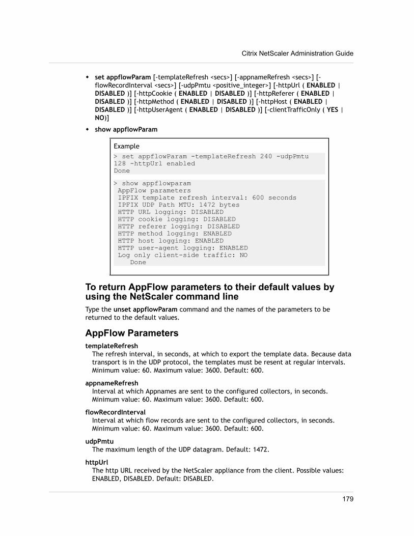
w set appflowParam [-templateRefresh <secs>] [-appnameRefresh <secs>] [-flowRecordInterval <secs>] [-udpPmtu <positive_integer>] [-httpUrl ( ENABLED |DISABLED )] [-httpCookie ( ENABLED | DISABLED )] [-httpReferer ( ENABLED |DISABLED )] [-httpMethod ( ENABLED | DISABLED )] [-httpHost ( ENABLED |DISABLED )] [-httpUserAgent ( ENABLED | DISABLED )] [-clientTrafficOnly ( YES |NO)]
w show appflowParam
Example> set appflowParam -templateRefresh 240 -udpPmtu 128 -httpUrl enabledDone> show appflowparam AppFlow parameters IPFIX template refresh interval: 600 seconds IPFIX UDP Path MTU: 1472 bytes HTTP URL logging: DISABLED HTTP cookie logging: DISABLED HTTP referer logging: DISABLED HTTP method logging: ENABLED HTTP host logging: ENABLED HTTP user-agent logging: ENABLED Log only client-side traffic: NO Done
To return AppFlow parameters to their default values byusing the NetScaler command lineType the unset appflowParam command and the names of the parameters to bereturned to the default values.
AppFlow ParameterstemplateRefresh
The refresh interval, in seconds, at which to export the template data. Because datatransport is in the UDP protocol, the templates must be resent at regular intervals.Minimum value: 60. Maximum value: 3600. Default: 600.
appnameRefreshInterval at which Appnames are sent to the configured collectors, in seconds.Minimum value: 60. Maximum value: 3600. Default: 600.
flowRecordIntervalInterval at which flow records are sent to the configured collectors, in seconds.Minimum value: 60. Maximum value: 3600. Default: 600.
udpPmtuThe maximum length of the UDP datagram. Default: 1472.
httpUrlThe http URL received by the NetScaler appliance from the client. Possible values:ENABLED, DISABLED. Default: DISABLED.
Citrix NetScaler Administration Guide
179
httpCookieInclude the cookie that was in the HTTP request received by the NetScaler appliancefrom the client. Possible values: ENABLED, DISABLED. Default: DISABLED.
httpRefererInclude the Web page that was last visited by the client. Possible values: ENABLED,DISABLED. Default: DISABLED.
httpMethodInclude the method that was specified in the HTTP request received by the NetScalerappliance from the client. Possible values: ENABLED, DISABLED. Default: DISABLED.
httpHostInclude the host identified in the HTTP request received by the NetScaler appliancefrom the client. Possible values: ENABLED, DISABLED. Default: DISABLED.
httpUserAgentInclude the client application through which the HTTP request was received by theNetScaler appliance. Possible values: ENABLED, DISABLED. Default: DISABLED.
clientTrafficOnlyGenerate AppFlow records only for the traffic from the client. Possible values: YES,NO. Default: NO.
To set the AppFlow parameters by using the configurationutility1. In the navigation pane, click AppFlow.
2. On the AppFlow landing page, under Settings, click Change AppFlow Settings.
3. In the Configure AppFlow Settings dialog box, specify values for the followingparameters, which correspond to parameters described in "AppFlow Parameters" asshown:
• Template Refresh Interval—templateRefresh
• AppName Refresh Interval—appnameRefresh
• Flow Record Export Interval—flowRecordInterval
• HTTP URL—httpUrl
• HTTP Cookie—httpCookie
• HTTP Referer—httpReferer
• HTTP Method—httpMethod
• HTTP Host—httpHost
• HTTP User-Agent—httpUserAgent
• Template Refresh Interval—templateRefresh
• UDP Maximum Transmission Unit—udpPmtu
4. Click OK, and then click Close.
Chapter 7 Enhanced Application Visibility Using AppFlow
180
Chapter 8
Reporting Tool
Topics:• Using the Reporting Tool
• Stopping and Starting theData Collection Utility
Use the Citrix® NetScaler® Reporting tool to view NetScalerperformance statistics data as reports. Statistics data arecollected by the nscollect utility and are stored in a database.When you want to view certain performance data over aperiod of time, the Reporting tool pulls out specified datafrom the database and displays them in charts.
Reports are a collection of charts. The Reporting tool providesbuilt-in reports as well as the option to create custom reports.In a report, you can modify the charts and add new charts.You can also modify the operation of the data collectionutility, nscollect, and stop or start its operation.
181
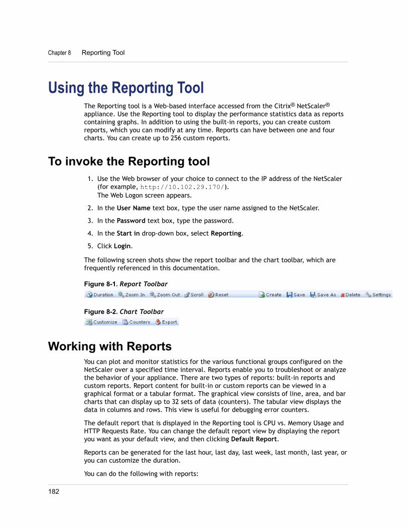
Using the Reporting ToolThe Reporting tool is a Web-based interface accessed from the Citrix® NetScaler®
appliance. Use the Reporting tool to display the performance statistics data as reportscontaining graphs. In addition to using the built-in reports, you can create customreports, which you can modify at any time. Reports can have between one and fourcharts. You can create up to 256 custom reports.
To invoke the Reporting tool1. Use the Web browser of your choice to connect to the IP address of the NetScaler
(for example, http://10.102.29.170/).The Web Logon screen appears.
2. In the User Name text box, type the user name assigned to the NetScaler.
3. In the Password text box, type the password.
4. In the Start in drop-down box, select Reporting.
5. Click Login.
The following screen shots show the report toolbar and the chart toolbar, which arefrequently referenced in this documentation.
Figure 8-1. Report Toolbar
Figure 8-2. Chart Toolbar
Working with ReportsYou can plot and monitor statistics for the various functional groups configured on theNetScaler over a specified time interval. Reports enable you to troubleshoot or analyzethe behavior of your appliance. There are two types of reports: built-in reports andcustom reports. Report content for built-in or custom reports can be viewed in agraphical format or a tabular format. The graphical view consists of line, area, and barcharts that can display up to 32 sets of data (counters). The tabular view displays thedata in columns and rows. This view is useful for debugging error counters.
The default report that is displayed in the Reporting tool is CPU vs. Memory Usage andHTTP Requests Rate. You can change the default report view by displaying the reportyou want as your default view, and then clicking Default Report.
Reports can be generated for the last hour, last day, last week, last month, last year, oryou can customize the duration.
You can do the following with reports:
Chapter 8 Reporting Tool
182
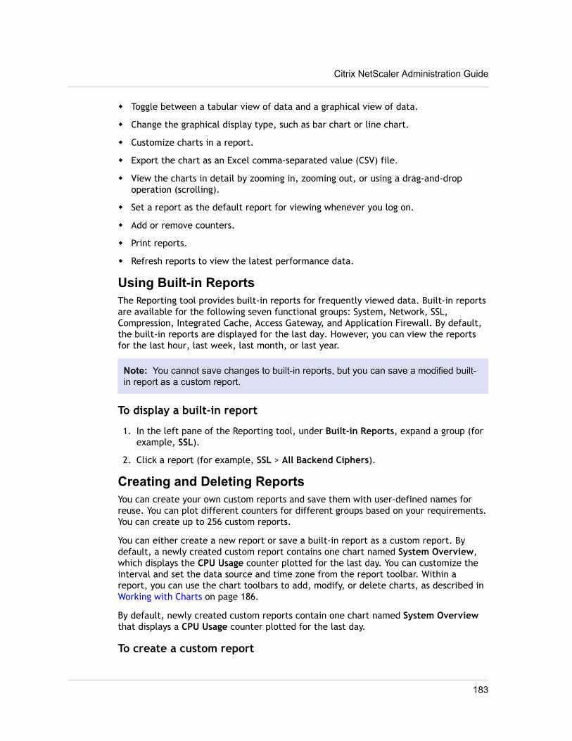
w Toggle between a tabular view of data and a graphical view of data.
w Change the graphical display type, such as bar chart or line chart.
w Customize charts in a report.
w Export the chart as an Excel comma-separated value (CSV) file.
w View the charts in detail by zooming in, zooming out, or using a drag-and-dropoperation (scrolling).
w Set a report as the default report for viewing whenever you log on.
w Add or remove counters.
w Print reports.
w Refresh reports to view the latest performance data.
Using Built-in ReportsThe Reporting tool provides built-in reports for frequently viewed data. Built-in reportsare available for the following seven functional groups: System, Network, SSL,Compression, Integrated Cache, Access Gateway, and Application Firewall. By default,the built-in reports are displayed for the last day. However, you can view the reportsfor the last hour, last week, last month, or last year.
Note: You cannot save changes to built-in reports, but you can save a modified built-in report as a custom report.
To display a built-in report
1. In the left pane of the Reporting tool, under Built-in Reports, expand a group (forexample, SSL).
2. Click a report (for example, SSL > All Backend Ciphers).
Creating and Deleting ReportsYou can create your own custom reports and save them with user-defined names forreuse. You can plot different counters for different groups based on your requirements.You can create up to 256 custom reports.
You can either create a new report or save a built-in report as a custom report. Bydefault, a newly created custom report contains one chart named System Overview,which displays the CPU Usage counter plotted for the last day. You can customize theinterval and set the data source and time zone from the report toolbar. Within areport, you can use the chart toolbars to add, modify, or delete charts, as described in Working with Charts on page 186.
By default, newly created custom reports contain one chart named System Overviewthat displays a CPU Usage counter plotted for the last day.
To create a custom report
Citrix NetScaler Administration Guide
183
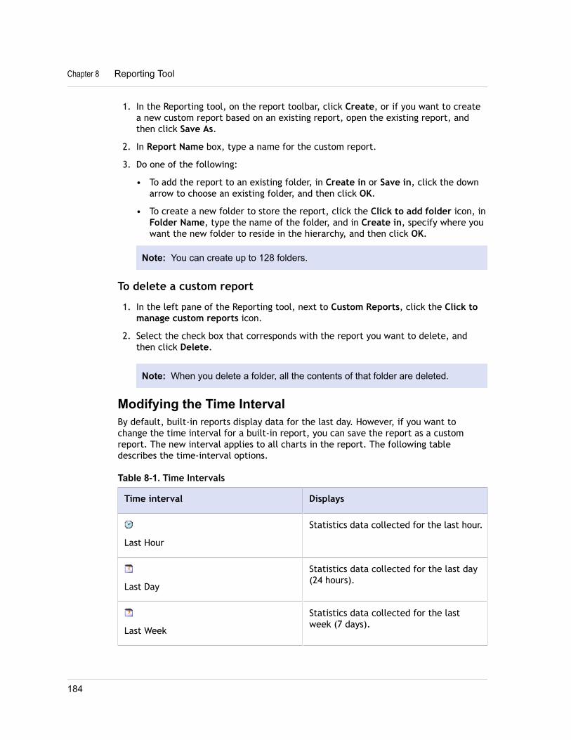
1. In the Reporting tool, on the report toolbar, click Create, or if you want to createa new custom report based on an existing report, open the existing report, andthen click Save As.
2. In Report Name box, type a name for the custom report.
3. Do one of the following:
• To add the report to an existing folder, in Create in or Save in, click the downarrow to choose an existing folder, and then click OK.
• To create a new folder to store the report, click the Click to add folder icon, inFolder Name, type the name of the folder, and in Create in, specify where youwant the new folder to reside in the hierarchy, and then click OK.
Note: You can create up to 128 folders.
To delete a custom report
1. In the left pane of the Reporting tool, next to Custom Reports, click the Click tomanage custom reports icon.
2. Select the check box that corresponds with the report you want to delete, andthen click Delete.
Note: When you delete a folder, all the contents of that folder are deleted.
Modifying the Time IntervalBy default, built-in reports display data for the last day. However, if you want tochange the time interval for a built-in report, you can save the report as a customreport. The new interval applies to all charts in the report. The following tabledescribes the time-interval options.
Table 8-1. Time Intervals
Time interval Displays
Last Hour
Statistics data collected for the last hour.
Last Day
Statistics data collected for the last day(24 hours).
Last Week
Statistics data collected for the lastweek (7 days).
Chapter 8 Reporting Tool
184
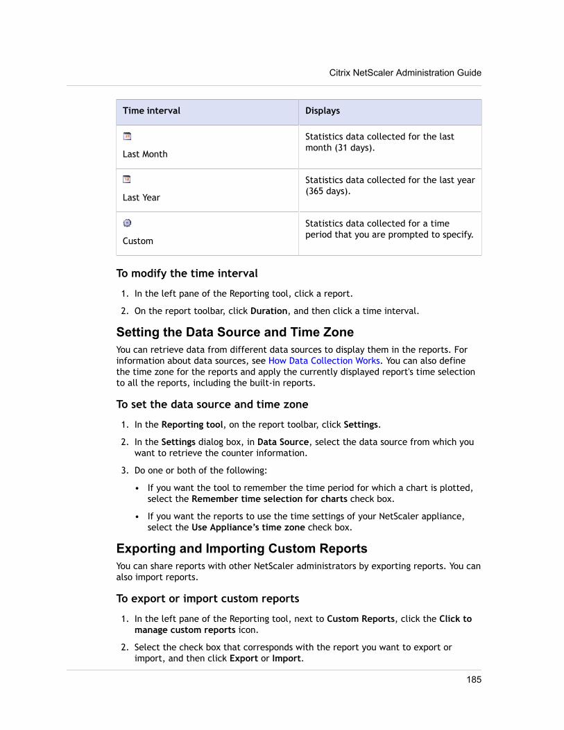
Time interval Displays
Last Month
Statistics data collected for the lastmonth (31 days).
Last Year
Statistics data collected for the last year(365 days).
Custom
Statistics data collected for a timeperiod that you are prompted to specify.
To modify the time interval
1. In the left pane of the Reporting tool, click a report.
2. On the report toolbar, click Duration, and then click a time interval.
Setting the Data Source and Time ZoneYou can retrieve data from different data sources to display them in the reports. Forinformation about data sources, see How Data Collection Works. You can also definethe time zone for the reports and apply the currently displayed report's time selectionto all the reports, including the built-in reports.
To set the data source and time zone
1. In the Reporting tool, on the report toolbar, click Settings.
2. In the Settings dialog box, in Data Source, select the data source from which youwant to retrieve the counter information.
3. Do one or both of the following:
• If you want the tool to remember the time period for which a chart is plotted,select the Remember time selection for charts check box.
• If you want the reports to use the time settings of your NetScaler appliance,select the Use Appliance’s time zone check box.
Exporting and Importing Custom ReportsYou can share reports with other NetScaler administrators by exporting reports. You canalso import reports.
To export or import custom reports
1. In the left pane of the Reporting tool, next to Custom Reports, click the Click tomanage custom reports icon.
2. Select the check box that corresponds with the report you want to export orimport, and then click Export or Import.
Citrix NetScaler Administration Guide
185
Note: When you export the file, it is exported in a .gz file format.
Working with ChartsUse charts to plot and monitor counters or groups of counters. You can include up tofour charts in one report. In each chart, you can plot up to 32 counters. The charts canuse different graphical formats (for example, area and bar). You can move the chartsup or down within the report, customize the colors and visual display for each counterin a chart, and delete a chart when you do not want to monitor it.
In all report charts, the horizontal axis represents time and the vertical axis representsthe value of the counter.
Adding a ChartWhen you add a chart to a report, the System Overview chart appears with the CPUUsage counter plotted for the last one day. To plot a different group of statistics orselect a different counter, see Modifying a Chart on page 186.
Note: If you add charts to a built-in report, and you want to retain the report, you mustsave the report as a custom report.
Use the following procedure to add a chart to a report.
To add a chart to a report
1. In the left pane of the Reporting tool, click a report.
2. Under the chart where you want to add the new chart, click the Add icon.
Modifying a ChartYou can modify a chart by changing the functional group for which the statistics aredisplayed and by selecting different counters.
To modify a chart
1. In the left pane of the Reporting tool, click a report.
2. Under the chart that you want to modify, click Counters.
3. In the dialog box that appears, in the Title box, type a name for the chart.
4. Next to Plot chart for, do one of the following:
• To plot counters for global counters, such as Integrated Cache and Compression,click System global statistics.
• To plot entity counters for entity types, such as Load Balancing and GSLB, clickSystem entities statistics.
5. In Select group, click the desired entity.
Chapter 8 Reporting Tool
186
6. Under Counters, in Available, click the counter name(s) that you want to plot, andthen click the > button.
7. If you selected System entities statistics in step 4, on the Entities tab, underAvailable, click the entity instance name(s) you want to plot, and then click the >button.
8. Click OK.
Viewing a ChartYou can specify the graphical formats of the plotted counters in a chart. Charts can beviewed as line charts, spline charts, step-line charts, scatter charts, area charts, barcharts, stacked area charts, and stacked bar charts. You can also zoom in, zoom out, orscroll inside the plot area of a chart. You can zoom in or out for all data sources for 1hour, 1 day, 1 week, 1 month, 1 year, and 3 years.
Other options for customizing the view of a chart include customizing the axes of thecharts, changing the background and edge color of the plot area, customizing the colorand size of the grids, and customizing the display of each data set (counter) in a chart.
Data set numbers, such as Data Set 1, correspond to the order in which the counters inyour graph are displayed at the bottom of the chart. For example, if CPU usage andMemory usage are displayed in first and second order at the bottom of the chart, CPUusage is equal to Data Set 1 and Memory usage is equal to Data Set 2.
Whenever you modify a built-in report, you need to save the report as a custom reportto retain your changes.
To change the graph type of a chart
1. In the left pane of the Reporting tool, select a report.
2. In the right pane, under the chart you want to view, on the chart toolbar, clickCustomize.
3. On the Chart tab, under Category, click Plot type, and then click the graph typeyou want to display for the chart. If you want to display the graph is 3D, select theUse 3D check box.
To refocus a chart with detailed data
1. In the left pane of the Reporting tool, select a report.
2. In the right pane, on the report toolbar, click Zoom In, and do one or both of thefollowing:
• To refocus the chart to display data for a specific time window, drag and dropthe cursor from the start time to the end time. For example, you can view datafor a one-hour period on a certain day.
• To refocus the chart to display data for a data point, simply click once on chartwhere you want to zoom in and get more detailed information.
Citrix NetScaler Administration Guide
187
3. Once you have the desired range of time for which you want to view detailed data,on the report toolbar, click Tabular View. Tabular view displays the data innumeric form in rows and columns.
To view numeric data for a graph
1. In the left pane of the Reporting tool, select a report.
2. In the right pane, on the report toolbar, click Tabular View. To return to thegraphical view, click Graphical View.
Note: You can also view the numeric data in the graphical view by hovering yourcursor over the notches in the gridlines.
To scroll through time in a chart
1. In the left pane of the Reporting tool, select a report.
2. In the right pane, on the report toolbar, click Scroll, and then click inside the chartand drag the cursor in the direction for which you want to see data for a new timeperiod. For example, if you want to view data in the past, click and drag to theleft.
To change the background color and text color of a chart
1. In the left pane of the Reporting tool, select a report.
2. In the right pane, under the chart for which you want to customize the axes, clickCustomize.
3. On the Chart tab, under Category, click one or more of the following:
• To change the background color, click Background Color, and then select theoptions for color, transparency, and effects.
• To change the text color, click Text Color, and then select the options for color,transparency, and effects.
To customize the axes of a chart
1. In the left pane of the Reporting tool, select a report.
2. In the right pane, under the chart for which you want to customize the axes, clickCustomize.
3. On the Chart tab, under Category, click one or more of the following:
• To change the scale of the left y-axis, click Left Y-Axis, and then select thescale you want.
• To change the scale of the right y-axis, click Right Y-Axis, in Data set to plot,select the date set, and then select the scale you want.
Note: The data set numbers, such as Data Set 1, correspond to the order inwhich the counters in your graph are displayed at the bottom of the chart. For
Chapter 8 Reporting Tool
188
example, if CPU usage and Memory usage are displayed in first and secondorder at the bottom of the chart, CPU usage is equal to Data Set 1 andMemory usage is equal to Data Set 2.
• To plot each data set in its own hidden y-axis, click Multiple Axes, and thenclick Enable.
To change the background color, edge color, and gridlines for a plotarea of a chart
1. In the left pane of the Reporting tool, select a report.
2. In the right pane, under the chart for which you want to customize the plot area,click Customize.
3. On the Plot Area tab, under Category, click one or more of the following:
• To change the background color and edge color of the chart, click BackgroundColor and Edge Color, and then select the options for color, transparency, andeffects.
• To change the horizontal or vertical grids of the chart, click Horizontal Grids orVertical Grids, and then select the options for displaying the grids, grid width,grid color, transparency, and effects.
To change the color and graph type of a data set
1. In the left pane of the Reporting tool, select a report.
2. In the right pane, under the chart for which you want to customize the display ofthe data set (counters), click Customize.
3. On the Data Set tab, in Select Data Set, select the data set (counter) for whichyou want to customize the graphical display.
Note: The data set numbers, such as Data Set 1, correspond to the order inwhich the counters in your graph are displayed at the bottom of the chart. Forexample, if CPU usage and Memory usage are displayed in first and secondorder at the bottom of the chart, CPU usage is equal to Data Set 1 and Memoryusage is equal to Data Set 2.
4. Under Category, do one of more of the following:
• To change the background color, click Color, and then select the options forcolor, transparency, and effects.
• To change the graph type, click Plot type, and then select the graph type youwant to display for the data set. If you want to display the graph as 3D, selectthe Use 3D check box.
Exporting Chart Data to ExcelFor further data analysis, you can export charts to Excel in a comma-separated value(CSV) format.
Citrix NetScaler Administration Guide
189
To export chart data to Excel
1. In the left pane of the Reporting tool, select a report.
2. In the right pane, under the chart with the data you want to export to Excel, clickExport.
Deleting a ChartIf you do not want to use a chart, you can remove it from the report. You canpermanently remove charts from custom reports only. If you delete a chart from a built-in report and want to retain the changes, you need to save the report as a custom report.
To delete a chart
1. In the left pane of the Reporting tool, select a report.
2. In the right pane, under the chart that you want to delete, click the Delete icon.
ExamplesTo display the trend report for CPU usage and memoryusage for the last week1. In the left pane of the Reporting tool, under Built-in Reports, expand System.
2. Click the report CPU vs. Memory Usage and HTTP Requests Rate.
3. In the right pane, on the report toolbar, click Duration, and then click Last Week.
To compare the bytes received rate and the bytestransmitted rate between two interfaces for the last week1. In the right pane, on the report toolbar, click Create.
2. In the Report Name box, type a name for the custom report (for example,Custom_Interfaces), and then click OK.
The report is created with the default System Overview chart, which displays theCPU Usage counter plotted for the last hour.
3. Under System Overview, on the chart toolbar, click Counters.
4. In the counter selection pane, in Title, type a name for the chart (for example,Interfaces bytes data).
5. In Plot chart for, click System entities statistics, and then in Select Group, selectInterface.
6. On the Entities tab, click the interface name(s) you want to plot (for example, 1/1and 1/2), and then click the > button.
7. On the Counters tab, click Bytes received (Rate) and Bytes transmitted (Rate)and then click the > button.
Chapter 8 Reporting Tool
190
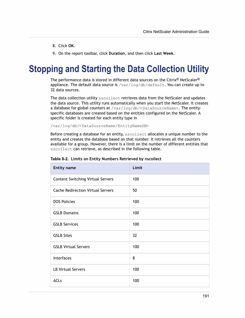
8. Click OK.
9. On the report toolbar, click Duration, and then click Last Week.
Stopping and Starting the Data Collection UtilityThe performance data is stored in different data sources on the Citrix® NetScaler®
appliance. The default data source is /var/log/db/default. You can create up to32 data sources.
The data collection utility nscollect retrieves data from the NetScaler and updatesthe data source. This utility runs automatically when you start the NetScaler. It createsa database for global counters at /var/log/db/<DataSourceName>. The entity-specific databases are created based on the entities configured on the NetScaler. Aspecific folder is created for each entity type in
/var/log/db/<DataSourceName/EntityNameDB>
Before creating a database for an entity, nscollect allocates a unique number to theentity and creates the database based on that number. It retrieves all the countersavailable for a group. However, there is a limit on the number of different entities thatnscollect can retrieve, as described in the following table.
Table 8-2. Limits on Entity Numbers Retrieved by nscollect
Entity name Limit
Content Switching Virtual Servers 100
Cache Redirection Virtual Servers 50
DOS Policies 100
GSLB Domains 100
GSLB Services 100
GSLB Sites 32
GSLB Virtual Servers 100
Interfaces 8
LB Virtual Servers 100
ACLs 100
Citrix NetScaler Administration Guide
191
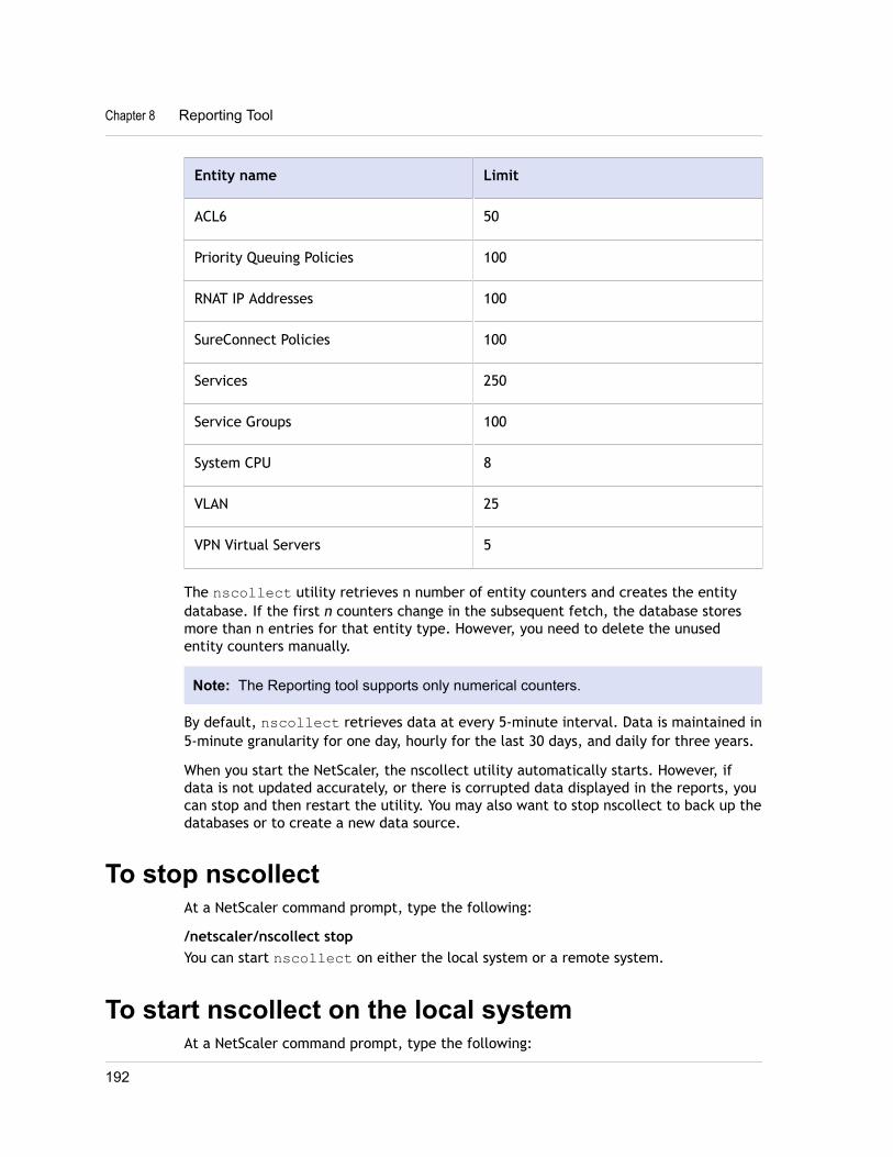
Entity name Limit
ACL6 50
Priority Queuing Policies 100
RNAT IP Addresses 100
SureConnect Policies 100
Services 250
Service Groups 100
System CPU 8
VLAN 25
VPN Virtual Servers 5
The nscollect utility retrieves n number of entity counters and creates the entitydatabase. If the first n counters change in the subsequent fetch, the database storesmore than n entries for that entity type. However, you need to delete the unusedentity counters manually.
Note: The Reporting tool supports only numerical counters.
By default, nscollect retrieves data at every 5-minute interval. Data is maintained in5-minute granularity for one day, hourly for the last 30 days, and daily for three years.
When you start the NetScaler, the nscollect utility automatically starts. However, ifdata is not updated accurately, or there is corrupted data displayed in the reports, youcan stop and then restart the utility. You may also want to stop nscollect to back up thedatabases or to create a new data source.
To stop nscollectAt a NetScaler command prompt, type the following:
/netscaler/nscollect stopYou can start nscollect on either the local system or a remote system.
To start nscollect on the local systemAt a NetScaler command prompt, type the following:
Chapter 8 Reporting Tool
192

/netscaler/nscollect start
To start nscollect on the remote systemAt a NetScaler command prompt, type the following:
/netscaler/nscollect start -U NS_IP:UserName:Password -ds DataSourceName
Example/netscaler/nscollect start -U 10.102.29.170:nsroot:nsroot -ds default
Citrix NetScaler Administration Guide
193