Embed Size (px)
Citation preview
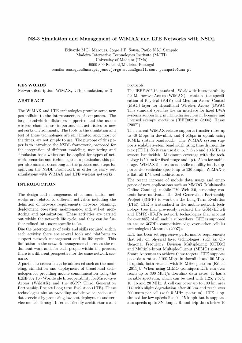
NS-3 Simulation and Management of WiMAX and LTE Networks with NSDL
Eduardo M.D. Marques, Jorge J.F. Sousa, Paulo N.M. SampaioMadeira Interactive Technologies Institute (M-ITI)
University of Madeira (UMa)9000-390 Funchal/Madeira, Portugal
emails: [email protected],[email protected], [email protected]
KEYWORDS
Network description, WiMAX, LTE, simulation, ns-3
ABSTRACT
The WiMAX and LTE technologies promise some newpossibilities to the interconnection of computers. Thelarge bandwidth, distances supported and the use ofwireless channels are important characteristics to newnetworks environments. The tools to the simulation andtest of these technologies are still limited and, most ofthe times, are not simple to use. The purpose of this pa-per is to introduce the NSDL framework, proposed forthe integration of different modeling, monitoring andsimulation tools which can be applied for types of net-work scenarios and technologies. In particular, this pa-per also aims at describing all the process and steps forapplying the NSDL Framework in order to carry outsimulations with WiMAX and LTE wireless networks.
INTRODUCTION
The design and management of communication net-works are related to different activities including thedefinition of network requirements, network planning,deployment, operation, maintenance, and, at last, mon-itoring and optimization. These activities are carriedout within the network life cycle, and they can be fur-ther refined into more specific tasks.
Due the heterogeneity of tasks and skills required withineach activity there are several tools and platforms tosupport network management and its life cycle. Thislimitation in the network management increases the re-dundant work and, for each people within the process,there is a different perspective for the same network sce-nario.
A particular scenario can be addressed such as the mod-eling, simulation and deployment of broadband tech-nologies for providing mobile communication using theIEEE 802.16 - Worldwide Interoperability for MicrowaveAccess (WiMAX) and the 3GPP Third GenerationPartnership Project Long term Evolution (LTE). Thesetechnologies aim at providing mobile voice, video anddata services by promoting low cost deployment and ser-vice models through Internet friendly architectures and
protocols.
The IEEE 802.16 standard - Worldwide Interoperabilityfor Microwave Access (WiMAX) - contains the specifi-cation of Physical (PHY) and Medium Access Control(MAC) layer for Broadband Wireless Access (BWA).This standard specifies the air interface for fixed BWAsystems supporting multimedia services in licensee andlicensed exempt spectrum (IEEE802.16 (2004), Hasan(2007)).
The current WiMAX release supports transfer rates upto 46 Mbps in downlink and 4 Mbps in uplink using10MHz system bandwidth. The WiMAX system sup-ports scalable system bandwidth using time division du-plex (TDD). So it can use 3.5, 5, 7, 8.75 and 10 MHz assystem bandwidth. Maximum coverage with the tech-nology is 50 km for fixed usage and up to 5 km for mobileusage. WiMAX focuses on nomadic mobility but it sup-ports also vehicular speeds up to 120 kmph. WiMAX isa flat, all IP-based architecture.
The recent increase of mobile data usage and emer-gence of new applications such as MMOG (MultimediaOnline Gaming), mobile TV, Web 2.0, streaming con-tents have motivated the 3rd Generation PartnershipProject (3GPP) to work on the Long-Term Evolution(LTE). LTE is a standard in the mobile network tech-nology tree that previously realized the GSM/EDGEand UMTS/HSxPA network technologies that accountfor over 85% of all mobile subscribers. LTE is supposedto ensure 3GPPs competitive edge over other cellulartechnologies (Motorola (2007)).
LTE has been set aggressive performance requirementsthat rely on physical layer technologies, such as, Or-thogonal Frequency Division Multiplexing (OFDM)and Multiple-Input Multiple-Output (MIMO) systems,Smart Antennas to achieve these targets. LTE supportspeak data rates of 100 Mbps in downlink and 50 Mbpsin uplink, both reached with 20 MHz spectrum (Erbele(2011)). When using MIMO techniques LTE can evenreach up to 300 Mbit/s downlink data rates. It has avariable spectrum, which can be used with 1.25, 2.5, 5,10, 15 and 20 MHz. A cell can cover up to 100 km area[14] with slight degradation after 30 km and reach over200 users per cell (with 5 MHz spectrum). LTE is op-timized for low speeds like 0 - 15 kmph but it supportsalso speeds up to 350 kmph. Round-trip times below 10

Figure 1: NSDL Framework layered architecture
ms can be accomplished [15].
In this case, different models, approaches and tools havebeen proposed in order to optimize and exploit the ad-vantages of these technologies through the simulation(Piro et al. (2010), Erbele (2011) and Ball et al. (????)).
Some of the existing solutions for the design and im-plementation of WiMAX and LTE technologies providean approach for some specific issues and problems, lim-ited to some specific domains, and, most of the times,having a scarce or incomplete documentation. It is alsoimportant to consider the functionalities provided bythese solutions. Some of them are very limited in termsof number of functionalities available and have a veryspecific application. Others are based on a large setof models and provide a more complex analysis over anetwork.
If all these solutions could be applied jointly in a co-ordinated way, they could provide a solid and help-ful environment for optimizing the management ofWiMAX/LTE networks. Nevertheless, the data formatsused in general by these existing solutions are very dis-tinct and, most of the times, incompatible.
In order to provide a generic solution for promotinginteroperability among different WiMAX/LTE networkmanagement tools, this paper presents a framework re-lying on the Network Scenarios Description Language(NSDL), which has been proposed as a common solutionthat can be applied to assist network managers with theoptimization of the network during its life cycle.
Figure 1 illustrates the layered organization of severalcomponents of the NSDL framework. The top and bot-tom layers represent the existing networks tools. Thetop layer represents the management tools to providethe modeling, monitoring and visualization of networks(e.g., GUIs such as, topology generators, operation andfailures monitoring, statistics and results, etc). The bot-tom layer represents the network analysis tools, such asnetwork simulators, management tools, security evalu-ation, etc. Actually, some of the existing managementplatforms support both bottom and upper layers; how-ever, most of them are purpose-oriented and are presentonly in one of the layers. The NSDL representation rep-resents a middleware layer to connect either layers ordifferent networks tools. The GUIs may read and writethe created network scenarios and, through specializedApplication Programming Interfaces (APIs), the bot-tom layer tools are invoked to execute some operationsover the network. In this paper we illustrate the uti-
lization of the NSDL framework to provide the networkmodeling and simulation of WiMAX/LTE networks.The remainder of paper is organized as follows: NSDLis introduced in Section 2. Section 3 introduces the con-cept of profile in NSDL, called an NS-3 profile. Section4 demonstrates how a translation from an NSDL de-scription to an NS-3 script can be obtained. Section5 addresses a brief case study related to the existingWiMAX and LTE modules for NS-3. At last, Section 6presents the main conclusions of this work.
NETWORK SCENARIOS DESCRIPTIONLANGUAGE
The purpose of the Network Scenario Description Lan-guage (NSDL) is to provide a vocabulary and a set ofrules, both able to support the description of wired andwireless data networks and the information of the con-texts, or domains, where those networks are used or eval-uated.In NSDL not only the network topology with its objectsand characteristics are described, but also the differ-ent context of use or evaluation that may occur overthat network. This separation is a new approach tonetworks description. NSDL allows first the descriptionof the objects (and components) of the network, theirrelations and properties, and it also allows the sepa-rate description of the network concerning different uti-lization contexts, such as simulation, management, etc.
Figure 2: NSDLfile structure
The principles applied to thedesign of NSDL were (1) sim-plicity, which means the lan-guage has to be simple and clearnot only to be manipulated byan application or tool, but alsopossible to be edited by a hu-man user with a simple texteditor; (2) definition of multi-ple abstraction levels, allowingto specify not only simple highlevel descriptions of a networkscenario, but also, if needed, tohave the possibility to create avery detailed description of allnetwork scenario objects and itsparameters; and (3) extensibil-ity, implying that new objectsand parameters can always beincorporated in future descriptions.The use of a single language description in several mo-ments of a network life cycle could be very advantageous.If the users responsible for the network are familiar withthat language, they can easily understand the currentstate of the network, thus the management of the net-work is optimized. Further integration capabilities canalso be achieved since developers of a network tool areable to add import and export capabilities from and

to NSDL, making their work interoperable with NSDLnetworks.Interoperability is indeed one important advantage ofNSDL. If a user deploys several NSDL compliant tools,he can easily analyze a network using each one of them,thus obtaining integrated results. For instance, NSDLcan be useful when the user needs to execute two sim-ilar simulations of the same network, with two differ-ent simulators. Also, we can consider the case wherethe user needs to make use of a particular function ofa tool, normally not easily available due to the differ-ent network description languages applied by the tool,making the user to learn another language in order toimplement his code in a different format. NSDL can beextended by adding new parameters and by the creationnew objects over the already defined basic objects. Forinstance, NSDL can be extended to support the descrip-tion of wireless sensor networks. From the basic objectNode, we can define a new node, designated WirelessSensor Node, which will receive all node characteristics,and will add its components, such as, special interfacesand sensor networks protocols.The main goal of NSDL is to provide a rich descriptionof the network objects and their parameters and also adescription of the several network scenarios throughoutthe network life cycle. In this sense, the defined NSDLstructure and parameters should also be rich enough todescribe any type of data network and allow incorporat-ing in its definition data to support future objects andnew data networks.The technology underlying NSDL is XML (XML (2011))due its richness and flexibility. Indeed, XML providesthe specification of clear definitions and has a set ofavailable tools. Also, XML assures the validity of theNSDL principles: simplicity, abstraction and extensibil-ity.An NSDL representation is an XML file with two ba-sic elements (Figure 2): Network and Scenarios. TheNetwork element contains the description of a networkidentifying its objects and its parameters. The Scenar-ios element may contain several descriptions, each onereferring to a specific use, or context, to that network.The Network element is composed of Templates, Ob-jects and Views. Since the Objects element containsthe description of the network topology, it is the maincomponent of the language. This element is composedof nodes, links and domains. Some other important, butnot mandatory elements are Templates and Views. TheTemplates element is important to simplify the descrip-tion of similar objects. The Views element is a mecha-nism applied to group network objects to be used in thescenarios.In the Scenarios element, two elements are introduced:Visualization and Simulation. The Visualization ele-ment provides additional information to enrich the net-work description, such as objects positioning in theGUIs and graphical data. All the parameters needed
to implement a particular simulation over the networkusing a generic or particular simulation tool is definedin the Simulation element.A last organization element present in the NSDL lan-guage is the profile. Briefly, an NSDL profile is a setof NSDL objects and/or scenarios with some relationamong them. Profiles were defined in order to simplifythe management of the several objects already defined,and the other objects still to be defined in the future,and; to make clearer the use of NSDL, providing a stan-dard mechanism to select only the needed objects in aparticular network domain scope. A last important ad-vantage of the profiles is the strengthening of the inter-operability purpose of NSDL. The existence of profileswill guide users to the use of the same objects, promot-ing the re-use or improvement of already defined ele-ments, as an alternative to the definition of new networkelements.The types of profiles defined for NSDL were the ObjectsProfiles and the Tools Profiles. The first type of profileenables the user to create groups of network elements, ofany kind. As example, consider the Basic Objects Pro-file, the simpler profile in NSDL, with six basic objects.Another example is the Wireless profile containing allthe wireless related network elements. It is also possibleto define a profile by the combination of other objectsprofiles, besides the profile network elements. The sec-ond type of profiles, the Tools Profiles, adds to the net-work elements, the scenarios supported by a particulartool. An example is the NS-3 profile with its networkelements and the visualization and simulation scenar-ios. Figure 3 illustrates the definition of several profiles,including some of the profiles stated as examples.In the next section a case study is presented to illustratethe utilization of the NSDL framework focusing in somewireless scenarios.
DESCRIBING WIMAX/LTE NETWORKSWITH NSDL
As introduced in the previous section, an NSDL toolprofile consists of a set of objects and scenarios withspecific lexical and semantic rules in order to accommo-date the language specification for a network tool. Thetool profiles already defined for NSDL are related totwo simulation platforms: Network Simulator 2 (ns-2)(ns (2011)) and Network Simulator 3 (NS-3) (Hender-son et al. (2008)). When a network scenario is describedusing NSDL, it is possible to translate these xml descrip-tions to a specific output script (e.g., OTcl (Wetherallet al. (1995)) for ns-2 and C++ (Stroustrup (1980)) forNS-3) and, consequently, that allow researchers to exe-cute that scenario on the respective tool related to thedefined NSDL profile. The illustration of the mappingprocess is detailed in Section 6. The NSDL profile forNS-3 includes the objects and the scenarios presented inFigure 3. A set of objects is illustrated as Network Ob-

Figure 3: Several examples of NSDL profiles, both Network Objects profiles and Tool profile (this last includes thescenarios)
jects, composed of Generic Objects, Base TCP/IP Ob-jects and Wireless Objects. The following NSDL Objectprofiles were defined:
• Generic Objects Holds the highest level of ab-straction for the various objects that are typicallypresent in common network scenarios;
• Base TCP/IP Objects contains the well-knownTCP/IP object, such as, Internet protocol, TCPand UDP transport protocols, along with other net-work elements, and;
• Wireless Objects - this group contains the specifiedwireless network domains: Wireless Fidelity (Wi-Fi), WiMAX and LTE.
An NSDL tool profile to be complete needs, besides theobjects profiles, one or more scenarios and, in the caseof NS-3, the selected and defined scenarios were Visual-ization and Simulation.Notice that a special focus was given to the wireless ap-proach when defining an NS-3 profile for NSDL, sinceNS-3 developers have been focusing their attention onthese network solutions as well (Farooq and Turletti(2009), Piro et al. (2010), Krill and Boyko (2010)).Therefore, this case illustrates how NSDL describesspecifically the WiMAX and LTE objects.In a WiMAX environment the Base Station (BS) andSubscribed Station (SS) roles determine that a BS func-
tion is to transmit and manage exchanged flows betweenSSs and a SS is either a source or a destination of flows,so, the NSDL description should reflect those character-istics. Figure 4 illustrates an NSDL description for bothBase Station (BS) and Subscriber Station (SS) used ina WiMAX environment.
The BS and SSs in our scenarios are simple nodes.The distinction between them occurs in the in-terface element (<wlan802.16>) and more preciselythe <type> attribute. The BS <ipv4> elementholds the IPv4 specifications to configure a LANNetwork, using the attributes <net.address/> and<net.mask/>. The <interface.id/> references the in-terface (<wlan802.16/>), which is optional if there isonly one, but mandatory in case of having several in-terfaces. Thus, this ipv4 configuration will be per-formed by the BS, assigning IPv4 and the respectivemask to the remaining nodes (i.e. the SS), as re-quired by the NS-3 simulator. Optionally, a modulationtype Quadrature Amplitude Modulation (QAM) 16/12(<modulation.type/>) for signal is set on SSs.
Similarly, Figure 5 describes Enhanced NodeB (eNB)and User Equipment (UE) configurations used in LTEnetworks. Herein it is possible to observe the similar-ity between both BS/eNB and SS/UE specifications interms of NSDL structure. Again for eNB, IPv4 is setfor LAN purposes and <lte/> element only needs toknow which kind of station has been dealt with (config-

Figure 4: BS (node4) and SS (node5) sample configura-tion
Figure 5: eNB (node4) and UE (node5) sample config-uration
ured with parameter <type/>). In the case of UE cell(node5), a reference to the associated eNB is mandatoryin order to register this UE cell to its corresponding eNB.
This section presented the very basic configuration tothe main nodes that will be object of study in the fol-lowing Sections. The next section demonstrates how anNSDL configuration (as the ones depicted in Figures 4and 5) can result in an NS-3 codification.
MAPPING NSDL TO NS-3
The main goal of this section is to demonstrate howNSDL structures are successfully and correctly trans-lated to the correspondent language behind the under-lying NSDL tool profile. Figure 6 depicts the process ofthis translation, showing step by step which operationsare used to handle the input file (i.e. an XML structurewith existing NSDL tags of a certain profile, in this case,
Figure 6: NSDL to NS-3 Mapping process
NSDL NS-3 profile).
The first two steps are the validations that will occurto verify the correctness of the Input File and they areLexical and Semantic validation. The Lexical will verifyif all objects and properties are correct. The Seman-tic will test if some dependencies and rules are fulfilled.These validations steps are performed with a set XMLSchemas, each one with some particular validations.
The last step is the File generation where an output fileis created, making use of sequential template calls by aneXtensible Stylesheet Language Transformation (XSLT)(XSLT (2011)) file that helps to carry out this action;The purpose of the template calls is to generate a correctsequence for a typical NS-3 script which is given by thefollowing structure:
1. Inclusion of main NS-3 libraries;
2. Definition of eventual global variables (Realtimeand CheckSum, for example);
3. Instantiation of Helpers to cover a set of possiblescenarios (LteHelper, WimaxHelper, MeshHelper,etc.);
4. Definition of typical ports to be used by applica-tions (UDPport = 9, TCPport = 50000);
5. Node(s) instantiation(s) and its specifications (i.e.Computer for an instance);
6. Internet installation and global scenario routing(AODV, OLSR, DSDV, etc.);
7. Link(s) creation and parameterization set
(P2PChannel, OfdmSimpleWimaxChannel, Spec-trumChannel, etc.);
8. Interface(s) definition (main devices that NS-3script will include BaseStationNetDevice, EnbNet-Device, etc.);
9. Node(s) Addressing (IPv4, IPv6);
10. Application(s) definition along with its parame-ters (Servers) and respective schedule events (Starttime, Stop time);
11. PacketSink definition and its schedule events (Starttime, Stop time);
12. Simulation main attributes configuration (Simula-tion Start time, Stop time, simulator destructor,etc.);
13. Visualization setting (allowed area for simulationexisting node(s) and its (their) specification(s) con-cerning mobility model (defines typically spatial po-sition and velocity), and;
14. Output file(s) creation (Trace files (.tr), Pcap files(.pcap), etc.).
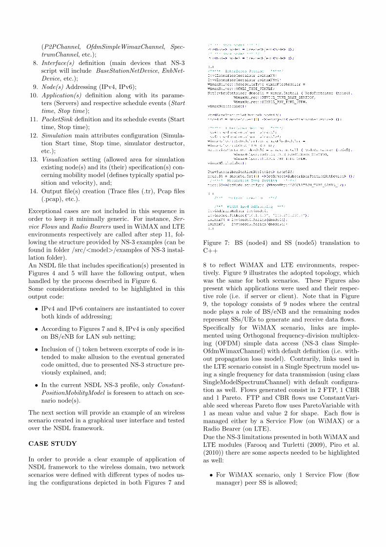
Exceptional cases are not included in this sequence inorder to keep it minimally generic. For instance, Ser-vice Flows and Radio Bearers used in WiMAX and LTEenvironments respectively are called after step 11, fol-lowing the structure provided by NS-3 examples (can befound in folder /src/<model>/examples of NS-3 instal-lation folder).An NSDL file that includes specification(s) presented inFigures 4 and 5 will have the following output, whenhandled by the process described in Figure 6.Some considerations needed to be highlighted in thisoutput code:
• IPv4 and IPv6 containers are instantiated to coverboth kinds of addressing;
• According to Figures 7 and 8, IPv4 is only specifiedon BS/eNB for LAN sub netting;
• Inclusion of () token between excerpts of code is in-tended to make allusion to the eventual generatedcode omitted, due to presented NS-3 structure pre-viously explained, and;
• In the current NSDL NS-3 profile, only Constant-PositionMobilityModel is foreseen to attach on sce-nario node(s).
The next section will provide an example of an wirelessscenario created in a graphical user interface and testedover the NSDL framework.
CASE STUDY
In order to provide a clear example of application ofNSDL framework to the wireless domain, two networkscenarios were defined with different types of nodes us-ing the configurations depicted in both Figures 7 and
Figure 7: BS (node4) and SS (node5) translation toC++
8 to reflect WiMAX and LTE environments, respec-tively. Figure 9 illustrates the adopted topology, whichwas the same for both scenarios. These Figures alsopresent which applications were used and their respec-tive role (i.e. if server or client). Note that in Figure9, the topology consists of 9 nodes where the centralnode plays a role of BS/eNB and the remaining nodesrepresent SSs/UEs to generate and receive data flows.
Specifically for WiMAX scenario, links are imple-mented using Orthogonal frequency-division multiplex-ing (OFDM) simple data access (NS-3 class Simple-OfdmWimaxChannel) with default definition (i.e. with-out propagation loss model). Contrarily, links used inthe LTE scenario consist in a Single Spectrum model us-ing a single frequency for data transmission (using classSingleModelSpectrumChannel) with default configura-tion as well. Flows generated consist in 2 FTP, 1 CBRand 1 Pareto. FTP and CBR flows use ConstantVari-able seed whereas Pareto flow uses ParetoVariable with1 as mean value and value 2 for shape. Each flow ismanaged either by a Service Flow (on WiMAX) or aRadio Bearer (on LTE).
Due the NS-3 limitations presented in both WiMAX andLTE modules (Farooq and Turletti (2009), Piro et al.(2010)) there are some aspects needed to be highlightedas well:
• For WiMAX scenario, only 1 Service Flow (flowmanager) peer SS is allowed;

Figure 8: eNB (node4) and UE (node5) translation toC++
Figure 9: WiMAX and LTE network scenario topologyand its applications
• For LTE scenario, currently only downlink sched-uler is implemented which means no uplink flowsto eNB is possible with the present module.
Since the main focus of this paper is to introduce theNSDL description and the NS-3 implementation forWiMAX and LTE, the results of the simulation are notfurther exploited. Moreover, according to previous lim-itations, no viable comparison between both technolo-gies can be achieved with the current NS-3 modules,but some useful data can be obtained as shown in Table1. Data presented in this table is obtained using FlowMonitor module (Carneiro et al. (2009)) integrated inthe existing NS-3 official version.
The only variable not directly extracted from Flow Mon-itor is Throughput, in Mbps, which is calculated withthe formula (1).
Throughput = RxB ∗ 4 ∗ 8/1024/1024/time (1)
Where RxB represents the amount of bytes received bya destination node, value recorded by Flow Monitor.Note that flows 1 to 4 are the current flows generatedby explicit OnOffApplications used in the NS-3 scripts.Flows 1 and 2 work under TCP protocol (2 FTP appli-cations) while flows 3 and 4 are transmitted over UDPprotocol (CBR and Pareto applications). Flows 5 and6 are Acknowledgement signals for source node, derivedfrom flows 1 and 2.
The results obtained show that observed delay values areacceptable for both technologies, with a slightly betterperformance for LTE. Jitter values in WiMAX scenarioare unacceptable, in particular when considering thatflows 3 and 4 may represent Video conferences, VoIPtransmission which is impossible to establish a good per-formance. Once again LTE presents better jitter valuesthan WiMAX. Calculated throughput is higher for LTEin all flows comparatively to WiMAX. These results re-flect the fact that uplink for LTE environment is notavailable yet which means WiMAX flows are transmit-ted twice while LTE flows are transmitted directly fromeNB to UEs. Although, other studies which tested bothtechnologies gave advantage for LTE, the observed dif-ferences were minimal (Ball et al. (????), Erbele (2011),Motorola (2007) and Raut (2009)).
CONCLUSION
The purpose of this work was to illustrate the deploy-ment of the NSDL framework in order to support thelife cycle of wireless network scenarios (modeling, simu-lation and analysis) based on existing simulators, such asNS-3. The process of obtaining the C++ script respect-ing the structure of an NS-3 simulation was introducedwhich illustrated the translation of an XML network de-scription to a specific C++ simulation code.
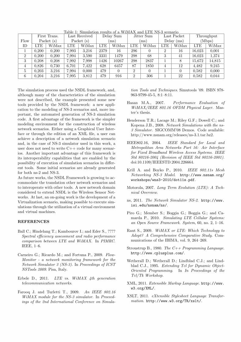
Table 1: Simulation results of a WiMAX and LTE NS-3 scenarioFirst Trans. Last Received Delay Sum Jitter Sum Last Packet Throughput
Flow Packet (s) Packet (s) (ms) (ms) Delay (ms) (Mbps)ID LTE WiMax LTE WiMax LTE WiMax LTE WiMax LTE WiMax LTE WiMax1 0,200 0,200 7,993 3,216 2379 16 296 0 2 16 16,023 0,0012 0,200 0,200 7,994 3,590 3331 1479 298 68 3 41 16,023 1,3743 0,208 0,208 7,992 7,998 1426 10267 298 2837 1 8 15,672 14,8154 0,826 0,730 6,701 7,422 628 6457 87 1850 4 12 4,482 9,2455 0,203 3,216 7,994 0,000 479 0 2 0 1 0 0,582 0,0006 0,204 3,216 7,995 3,812 479 916 2 306 1 22 0,582 0,044
The simulation process used the NSDL framework, and,although many of the characteristics of the simulationwere not described, the example presented some newtools provided by the NSDL framework: a new appli-cation to the modeling of NS-3 scenarios and, more im-portant, the automated generation of NS-3 simulationcode. A first advantage of the framework is the simplermodeling environment for the construction of wirelessnetwork scenarios. Either using a Graphical User Inter-face or through the edition of an XML file, a user canachieve a description of a network simulation scenarioand, in the case of NS-3 simulator used in this work, auser does not need to write C++ code for many scenar-ios. Another important advantage of this framework isits interoperability capabilities that are enabled by thepossibility of execution of simulation scenarios in differ-ent tools. Some initial scenarios are already generatedfor both ns-2 and NS-3.As future works, the NSDL Framework is growing to ac-commodate the translation other network scenarios andto interoperate with other tools. A new network domainconsidered to extend NSDL is the Wireless Sensor Net-works. At last, an on-going work is the development of aVirtualization scenario, making possible to execute sim-ulations through the utilization of a virtual environmentand virtual machines.
REFERENCES
Ball C.; Hindelang T.; Kambourov I.; and Eder S., ????Spectral efficiency assessment and radio performancecomparison between LTE and WiMAX. In PIMRC.IEEE, 1–6.
Carneiro G.; Ricardo M.; and Fortuna P., 2009. Flow-Monitor - a network monitoring framework for theNetwork Simulator 3 (NS-3). In Proceedings of ICSTNSTools 2009. Pisa, Italy.
Erbele D., 2011. LTE vs. WiMAX 4th generationtelecommunication networks.
Farooq J. and Turletti T., 2009. An IEEE 802.16WiMAX module for the NS-3 simulator. In Proceed-ings of the 2nd International Conference on Simula-
tion Tools and Techniques. Simutools ’09. ISBN 978-963-9799-45-5, 8:1–8:11.
Hasan M.A., 2007. Performance Evaluation ofWiMAX/IEEE 802.16 OFDM Physical Layer. Mas-ter’s thesis.
Henderson T.R.; Lacage M.; Riley G.F.; Dowell C.; andKopena J.B., 2008. Network Simulations with the ns-3 Simulator. SIGCOMM’08 Demos. Code available:http://www.nsnam.org/releases/ns-3.1.tar.bz2.
IEEE802.16, 2004. IEEE Standard for Local andMetropolitan Area Networks Part 16: Air Interfacefor Fixed Broadband Wireless Access Systems. IEEEStd 80216-2004 (Revision of IEEE Std 80216-2001).doi:10.1109/IEEESTD.2004.226664.
Krill A. and Boyko P., 2010. IEEE 802.11s MeshNetworking NS-3 Model. http://www.nsnam.org/
workshops/wns3-2010/dot11s.pdf.
Motorola, 2007. Long Term Evolution (LTE): A Tech-nical Overview.
ns, 2011. The Network Simulator NS-2. http://www.
isi.edu/nsnam/ns/.
Piro G.; Member S.; Boggia G.; Boggia G.; and Ca-marda P., 2010. Simulating LTE Cellular Systems:an Open Source Framework. System, 60, no. 2, 1–16.
Raut S., 2009. WiMAX or LTE: Which Technology toAdopt? A Comprehensive Comparative Study. Com-munications of the IBIMA, vol. 9, 264–269.
Stroustrup B., 1980. The C++ Programming Language.http://www.cplusplus.com/.
Wetherall D.; Wetherall D.; Lindblad C.J.; and Lind-blad C.J., 1995. Extending Tcl for Dynamic Object-Oriented Programming. In In Proceedings of theTcl/Tk Workshop.
XML, 2011. Extensible Markup Language. http://www.w3.org/XML/.
XSLT, 2011. eXtensible Stylesheet Language Transfor-mation. http://www.w3.org/TR/xslt/.