Embed Size (px)
Citation preview

NATIONAL RADIO llNSTITUTE
Complete p s e in PR.ACTICAL RADIO _._
lor
liannuuununuuummuuuuum;
= "muunuuuuNmu
IAA
APB
P wuM
uuuuuuuuuuuuuuuuuuuum u
RadioTrician wEG. U. F+. PAT. OFF.)
Lesson Text No. 23 (2nd Edition i
STANDARD RADIO RECEIVING
CIRCUITS
AMR
'71 {nian1utmu1wuuuuuuamunnuuuuuumuuuuuunuuuuuuauuuunuuuuuuuunuunìi.:,
(Originators of Radio Home Study Courses Est ablished 1914
Washington, D. C.
www.americanradiohistory.com

FRANKLIN said- "An investment in knowledge pays the best interest."
WHAT NOTES TO TAKE
A Personal Message from J. E. Smith
What notes should be taken in reading is a mat- ter largely of individual needs. Most students, in reading a book or listening to a lecture, take too many notes.
They then depend on their notes rather than their memory, which is always unwise. If one wants to look up data, he had better refer to the book rather than his own notes on the subject, unless, of course, it is a rare book which he may never have the opportunity to consult again. To the average student seeking simple knowledge of the subject, the taking of notes is principally to fix the points in mind. Some critical notes, too, are useful. Points which seem to be rather doubt- ful are worth noting, so that he may think them over later with more care.
Copyright 1929, 1930 by
NATIONAL RADIO INSTITUTE Washington, D. C.
BF5M-63030 Printed in U.S.A.
www.americanradiohistory.com

Radio -Trician's (REG. U.S. PAT. OFF.)
Complete Course in Practical Radio NATIONAL RADIO INSTITUTE WASHINGTON, D. C.
STANDARD RADIO RECEIVING CIRCUITS There are hundreds of Radio receiving circuits used by the
various manufacturers of both complete receivers and kits, which may all be classified under one of the following headings :
Fig. 1-Crystal receiving circuit
Non -regenerative. Regenerative. Reflex, which also includes the Inverse Duplex. Tuned Radio -frequency. Super -Heterodyne.
AERIAL GRID LEAK
VARIABLE CONDENSER +
GROUND 4 - 11111111111±j
GRID PLATE
PHONES
001 MF
RHEOSTAT
BATTERY B" BATTERY Fig. 2-Non-regenerative vacuum tube receiving circuit
Most of the above circuits have been carefully taken up in the earlier text -books, and in case any of the circuits presented in this book are not clearly understood from the brief descrip- tion, the student is advised to refer back to the text -book dealing with this particular class of receiving circuit.
1
www.americanradiohistory.com

One of the simplest forms and least expensive type of receiv- ing circuit of the non -regenerative type is the crystal receiver as shown in Figure 1. This outfit includes a variocoupler or radio - frequency transformer, a variable condenser, crystal detector or rectifier as it is sometimes called, and a pair of head -phones.
Fig. 3-Regenerative circuit using the tickler coil method
Under normal conditions, this type of receiver should give good head -phone reception from stations as far away as 25 miles. While this receiver is useful in cities where Broadcasting Sta- tions are close by, it is of little use in the suburbs and country.
Fig. 4-Regenerative circuit using the tuned plate method
From the fundamental circuit of the simplest form, we have the circuit of a vacuum tube receiver as shown in Figure 2. Although the first one uses a crystal detector and the second one a 3 -element vacuum tube, both are in the same category and are classified as belonging to the non -regenerative variety. The U. S. Bureau of Standards' measurements show that the vacuum tube is 25% more sensitive than the crystal although the latter gives 50% more clarity.
With the discovery of the 3 -element vacuum tube came the regenerative circuit. Regeneration increases the volume and sensitivity of a receiving set to a very large degree. There is
2
www.americanradiohistory.com

one draw -back, however, that of radiation. When the set starts to oscillate, it is due to over -regeneration.
A regenerative receiving circuit is shown in Figure 3, using the tickler feed-back method of regeneration. Regeneration can also be obtained through the use of a tuned plate circuit system, in which case the internal capacity of the vacuum tube plays an important role. Figure 4 shows the circuit diagram of a regenerative receiver using the tuned plate circuit method.
--AERIAL ROTOR (TICKLER)
Oí 0
\ SECONDARY
IPRIMARY
SWITCH -
GROUND
( DETECTOR AUDIO AMPLIFIER..
TUBE ¡TUBES
61 _ IIIU UUlilili 'A' BATTERY
Fig,. 5-Regenerative receiver in conjunction with two stages of audio -frequency amplification.
Figure 5 shows the circuit diagram of a standard 3 -tube regenerative receiver using two stages of audio -frequency ampli- fication after the detector tube.
REFLEX CIRCUITS
A Reflex receiver is sensitive, selective, and gives signals of excellent volume and clarity. The quality of reproduction depends greatly upon the inductive relations of the various coils. The circuit shown in Figure 6 is known as the Harkness single tube Reflex, and uses a special tuner and radio -frequency trans- former with a crystal detector.
Figure 7 shows a 2 -tube Reflex circuit using a stage of radio and audio -frequency amplification with a vacuum tube detector.
In ordinary single -tube non -regenerative receiving circuits, the received signals are rectified and partly amplified by the vacuum tube. To increase the volume of the incoming signals in these circuits, the usual procedure is to incorporate one or two stages of audio -frequency amplification. If the range of the receiver is to be increased, it is customary to incorporate one or
3
www.americanradiohistory.com

more stages of radio -frequency amplification. For every such stage added, another tube is necessary. Not so, however, in a Reflex circuit, where one tube is made to perform the duties of two or possibly three. The manner in which this is accomplished is quite simple.
For example, the incoming radio -frequency current is am- plified at radio -frequency by the vacuum tube, passed through a detector (which may be a crystal or vacuum tube), where they are rectified, and the resultant audio -frequency currents are passed through an audio -frequency transformer and then ampli- fied at audio -frequency, using the same vacuum tube. The audio - frequency currents then flow in the circuit containing the head- phones or loud -speaker.
Fig. 8-Harkness single tube reflex circuit using a crystal detector
The chief trouble with reflex amplification circuits is that they tend to oscillate at audio -frequency. That is, a continual squealing or howling noise is often obtained when the circuit is connected, and no matter what adjustments are made, it is usually difficult to eliminate. This trouble is due chiefly to the individual characteristics of the component parts and the design of the circuit.
With a circuit of this type, employing one tube and a crystal detector, it is possible to operate a loud -speaker and to receive over a great distance when employing the head -phones. With two tubes, of course, much better results can be obtained.
The only object in employing the reflex principle is to reduce the number of tubes employed for accomplishing a given result. It is now generally conceded that while the over-all amplifi- cation of a reflex set is greater than would be obtained with the
4
www.americanradiohistory.com

same number of tubes without reflexing, one tube when used both as a radio and audio -frequency amplifier, will not serve either function as efficiently as when used for only one of these purposes. It is also natural that the audio e. m. f.'s impressed on the input of the radio -frequency amplifier tube has a slight modulating effect on the high -frequency current and thereby produces a small amount of distortion. At all events, the lower- ing of the price of good vacuum tubes and the more general use of "A" and "B" Eliminators and AC tubes seem to have gone hand -in -hand with the swing of the public favor from reflex to
LOOSE COUPLING (1 MEG.
3-1, 4
6v -t. - +w- +.ß° - +`ß"
22í2Y. 90V Fig. 7-Two-tube Harkness reflex circuit
straight model receivers, such as tuned radio -frequency and the Super -Heterodyne.
INVERSE DUPLEX CIRCUIT
Reflexing, which is the foundation of the inverse duplex system, permits one tube to function as both a radio and audio - frequency amplifier. Where it is employed in a circuit, special attention must be paid to the function of the various parts under different conditions. For instance, small condensers offer very little impedance to high -frequency currents, but their impedance to current flow at the relatively low voice, or audio, frequencies is extremely high. The circuits can, therefore, be so arranged that they discriminate against low frequencies in favor of radio frequencies and vice versa. These principles are used in reflexing.
The inverse duplex system is superior to the straight reflex
5
www.americanradiohistory.com

system in several ways. It is more stable because any radio - frequency energy which passes the detector and first audio transformer through capacity coupling will only be impressed on the input of the stage ahead of the detector instead of two or
P
_IIiIiicUU Ql,UUIlUU41 ,, /6-22 V
P
Fig. 8-Three-tube Inverse duplex circuit
00025
00/ - s
//VVV 4nnQ//4//49
P/ V01_____
more stages ahead of it, as in the case of straight reflex. In the latter case, oscillation, due to feed-back, would be almost beyond
J lr ln J CF
Il'gR 3.. A F
RaCleen )d RF e RF J. Rf r As
a`e qi fi Ai 3.4 Rf C AF
Inverse Dupler 5,,1em
Fig. 9-Comparison of straight reflex with Inverse duplex system
control. In a straight reflex receiver, the first radio tube is usually the first audio amplifier also. Therefore, if any audio -fre- quency noises, such as a hum from power lines, are induced into the antenna and passed on to the first tube, they may be amplified
6
www.americanradiohistory.com

by the succeeding audio stages to loud -speaker volume. In the case of the inverse duplex system, the first radio tube is the last or next to the last audio amplifier. Hence, such noises seldom ever retain noticeable volume. Inverse duplexing also tends to equalize the load which the various tubes carry. This enables one to obtain a slightly greater output volume level before over- loading begins. Figure 8 shows a simple three -tube Inverse Duplex circuit, and Figure 9 the comparison of Straight -Reflex with the Inverse Duplex system.
Figure 10 shows the wiring diagram of the Grimes Inverse Duplex receiver. One of the greatest advantages of the inverse
s:r
0- 22e.v
C- 4§v
LOUD QI5lRí.Coll SPEAKER rJ2G
A- 3- 0+
2..o R 'Co. r9t 9JG
2.eAuOw
A+ B, Iñ, B 6v 22}v j9ov 136v
3Re R.F Co T,G 902 -
Fig. 10-Circu't diagram of Grimes inverse duplex receiver
n s
J
duplex system is its economy of tubes and battery power. This is especially apparent if the receiver is to be operated by means of dry batteries either in part or entirely. The principle of reflexipg has been applied to nearly all types of receiving circuits.
TUNED RADIO -FREQUENCY CIRCUITS
The popularity of 5 -tube tuned radio -frequency receivers was caused by a very peculiar patent situation. While this type of circuit employs 5 tubes and is no more sensitive than a 3 -tube regenerative circuit such as shown in Figure 5, it has many advantages that make it ideal for broadcast reception. The main advantages are non -radiation and simplified tuning. Thus, we see that due to the monopoly caused by the patent situation, the Radio public has benefited considerably.
A typical 5 -tube tuned radio -frequency circuit is shown in Figure I1. The main trouble in all receivers of this class is due
7
www.americanradiohistory.com

to coupling between the circuits causing oscillation, and in order to obtain amplification, it is necessary to prevent the circuits from oscillating. Several methods have been used for doing this, but only a few are satisfactory. In order to prevent feed-back coup- ling between the circuits, we must first understand where the feed-back occurs. Feed-back between the electrodes of the vacuum tube causes the most trouble. The grid and plate elec- trodes form a small condenser which couples the plate circuit to the grid circuit and causes oscillation. By means of a bridge connection, it has been possible to neutralize this tube capacity and the circuit is successfully used in Neutrodyne receivers. Feed-back also occurs between the coils themselves. The mag- netic and electrostatic fields of the coils extend far out into the surrounding space and energy is fed from the plate circuit to the grid circuit and oscillations are produced.
-AERIAL
eigli o CJ
RHEOSTAT
ó O
SWITCH
GROUND
'A' BATTERY WlI[f RHEOSTAT
Fig. 11-A typical five -tube tuned radio -frequency hook-up with filament circuit emphasized by heavy lines.
In the Neutrodyne type of receiver, feed-back between the coils has been reduced by mounting the coils at such an angle that their fields have no effect on adjacent coils. There are many ways of preventing self -oscillation in receivers of this type.
The first preventative was the potentiometer. This per- mitted biasing the grids of the radio -frequency tubes with va- rious values of either a positive or negative voltage. The manner in which the device was connected in a simple radio -frequency circuit is shown in Figure 12. If the vacuum tube or tubes had a tendency to oscillate, all one had to do was to move the arm of the potentiometer towards the positive side until everything was cleared up. This was good, except that in doing so, one in- troduced heavy losses in the circuit.
8
www.americanradiohistory.com

A fixed or variable resistance somewhere in the order of 200 to 1,000 ohms inserted in each grid circuit as shown in Figure 13 is another method that is very effective for stabilizing a set. However, this arrangement also is a "losser" and decreases both the sensitivity and selectivity of the set.
R.F.T.
POTENTIOMETER
R.FT.
A- A+ B+
Fig. 12-The potentiometer method of oscillation control
The first real advancement came with the introduction of the first original neutralization system exploited under the name of Neutrodyne. This method, worked out by Professor Hazeltine, supplied a means for neutralizing the effect of the internal grid to plate capacity of the vacuum tube. This was accomplished by the use of a small adjustable condenser (C), with a very low capacity value connected in the circuit as shown in Figure 14.
FIXED OR VARIABLE RESISTANCE
A- A+ 5+
Fig. 13 -Stabilizing a radio -frequency circuit by use of a series grid resistance
There is a very long explanation of the functioning of this ar- rangement in one of our previous lessons on the Neutrodyne receiver.
Referring to Figure 14, let us assume that the circuit is
operating without the neutralizing condenser C and that the grid or secondary circuits A and B are not tuned to any par- ticular station and are out of resonance with each other. In this case, there is very little regeneration taking place. However, as soon as we tune the circuits A and B to the wave -length of some Broadcasting Station, the point of resonance is reached
9
www.americanradiohistory.com

and there is sufficient feed-back of radio -frequency current through the internal capacity Cl of tube V, to cause oscillation in the manner heretofore explained. Though there is no variable condenser connected across the primary coil of R. F. T. to the plate circuit of tube V, the coil nevertheless takes on a resonance effect, due to the tuning of the associated secondary coil in circuit B. Now if we connect condenser C in the circuit, something else happens. This condenser introduces in the grid circuit A of tube V, a radio -frequency current equal, but opposite in phase, to the current fed back through the internal capacity Cl. In other words, there are two feed-backs-the natural feed- back through the capacity of the tube, and an auxiliary feed-back through the condenser C. Since these two distinct reactive cur- rents are opposite in phase, they neutralize each other, and con- sequently, oscillation cannot take place.
-A +A +B -A +A
FIg. 14-I1lustrating the Neutrodyne principle of oscillation control
The Rice system of neutralizing shown in Figure 15 is very similar to the Neutrodyne arrangement, but in this case, the condenser C is connected between the plate of the tube and the filament end of the grid coil. The action and effect is the same. That is, a current equal to the natural feed-back current, but opposite to it in phase, is fed back into the grid circuit.
There have been a number of other systems devised similar to the two just mentioned. They are all about equal in effective- ness. But they have one common fault, and that is that they do not act the same on all wave -lengths. Adjust a set using one of these forms of neutralization for stability on short waves, and there is a noticeable lack of sensitivity on the longer wave- lengths. If the set is adjusted for maximum sensitivity on long waves, it most certainly will oscillate on the short waves. Natu- rally, the best that can be done is to adjust the neutralizing sys-
10
www.americanradiohistory.com

tem so that the set is perfectly stable in operation on short waves, and then to be satisfied with the results obtained on the longer wave -lengths.
-A +A +g
Fig. 15-The Rice method of neutralization
RESISTANCE STABILIZATION
Radio engineers soon learned that there was still much to be done in the way of developing, stabilizing or neutralizing sys- tems. The main problem on hand was to devise a means to com- pensate for the change in electrical coupling between primary and secondary circuits at different wave -lengths. The problem was not an easy one as both capacities (condensers) and induc- tances (coils) change their reactance or impedance values with
Fig. 15-A plate -resistance stabilized circuit
a change in wave -length or frequency. The only factor that does not change is a resistance unit, and this provided the first form of stabilizer following the bridge circuit. This arrangement is shown in Figure 16. Although it is fairly effective in some re- spects, it has a number of disadvantages. At any rate, it can- not be truthfully called a damping device in the same sense that former arrangements were called.
It will be noticed on the diagram that a variable resistance (R) is connected in series with the common "B" supply leads to the plates of the radio -frequency tubes. The fact that the resist- ance is there means that there will be a certain amount of damp -
11
www.americanradiohistory.com

ing, but this is offset by the functioning of the resistance. In the first place, it is associated with the primary circuit only and does not act as a damping factor in the grid circuit, where it certainly would decrease both the selectivity and sensitivity of the set as a whole. What it does do is slightly damp the action of the pri- mary circuit, alter or adjust the plate -filament impedance of the radio -frequency tubes, and at the same move, you might say, adjust the "B" supply voltage.
CONSTANT COUPLING SYSTEM
The Loftin -White Constant Coupling System of radio -fre- quency amplification is a stabilized circuit with no theoretical losses to speak of, which is based on the fact that the reactance of a condenser increases as the frequency decreases, (or wave- length increases) and vice versa, and that the impedance of an
Fig. 17-The basic Loftin -White constant coupling system
inductance varies in exactly the opposite ratio. In other words, regardless of whether the wave -length is being increased or de- creased, the reactance of either the inductance or the capacity is increasing while the other is decreasing, as the case may be. The cir' uit of this system is shown in Figure 17. It has its in- ductance and capacity so connected that there is both inductive and capacitive coupling. It is a well-known fact that when two circuits are coupled together inductively, transfer of energy will be greatest at the lowest wave -length and least at the highest wave -length. When a capacitively coupled system is used, the effects obtained are just the opposite to those obtained with the inductively coupled system.
In the case of the capacitively coupled system, the energy transfer is lowest at the low wave and increases to the high point at the high wave -lengths.
It is logical to assume that by combining the good qualities of the two coupling systems a method can be evolved which will
12
www.americanradiohistory.com

add the two effects, thus obtaining equal energy transfer or amplification over the whole wave -length range. In the diagram of Figure 17, it can be seen that the inductive coupling is gained through the coils L1 and L2, while capacitive coupling is fur- nished by the condensers C1 and C2, and the connection to the primary Li. Coil L is a radio -frequency choke coil which pre- vents the leakage of any of the radio -frequency current into the "B" battery circuit, while "C" is the phase shifting condenser which is employed primarily for the purpose of neutralization.
The following diagrams show a number of popular manu- factured tuned radio -frequency receivers and the methods they employ for stabilization.
er J //r tr \ .º.r=ai;_[\ _ \ a` 1 7 -
r..n tomara
tee Iw .I eCO
de. COMI[rHt //I!I
OYtitrw.[[
/5
MOOf/.I/ /{V.O Rlfirni C/
Fig. 18-Model 35 Atwater Kent receiving circuit using series grid resistance
Figure 18 illustrates the circuit diagram of a six -tube At- water Kent receiver using series grid resistances for stabilizing the radio -frequency circuits. Figure 19 is the complete sche- matic diagram of a 5 -tube Neutrodyne circuit employing small neutralizing condensers between the grid circuits of the radio - frequency tubes. Figure 20 is a circuit diagram of the Karas Equamatic receiver using a movable primary, which varies the coupling as the tuning condenser capacity is varied. Figure 21
shows the circuit used in the Universal Plio-Six receiver. This employs a variable resistance (R) connected in the plate circuit of the first two tubes. Figure 22 shows the circuit diagram of a Freshman Masterpiece receiver. The primary of the radio -fre- quency coils are reversed to prevent oscillation. Figure 24A illustrates the circuit diagram of the Majestic AC Receiver, Model 90. This receiver has four stages of tuned radio -fre- quency, detector and push-pull audio -frequency amplification.
13
www.americanradiohistory.com
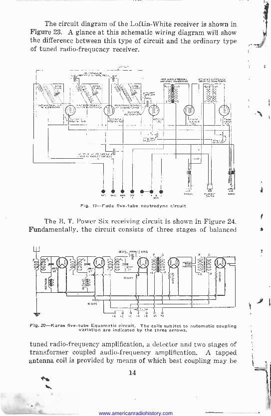
The circuit diagram of the Loftin -White receiver is shown in Figure 23. A glance at this schematic wiring diagram will show the difference between this type of circuit and the ordinary type of tuned radio -frequency receiver.
JI=NEViá °xr,DS-,,
OR MAT
no «EºoEa'. uE:na°DANìa
1
agf
i`ñ óá°"w., rPEwxcr
ec0°aNúcved'
V0 FEQ,[O á
e ro [5 ,.:e. O0. EA CTFli{ ME(I) 9Y,PA55 CCM MEE.
I N ANr. GOD. AMP. OV. - *
A
Fig. 19-Fada five -tube neutrodyne circuit
SwNrcCNr
The B. T. Power Six receiving circuit is shown in Figure 24. Fundamentally, the circuit consists of three stages of balanced
6 b i -A 4C -G A -8 45 90
Flg. 20-Karas five -tube Equamatic circuit. The coils subject to automatic coupling variation are indicated by the three arrows.
tuned radio -frequency amplification, a detector and two stages of transformer coupled audio -frequency amplification. A tapped antenna coil is provided by means of which best coupling may be
14 h
www.americanradiohistory.com

41
c0025 er ANTENNA
COIL
201-A
ANio GNDl
ANT.
( 1(
C.
.0002 MF.
IMF 90V. 6+
R.F.T.-" IN.FT. g.0\\1 pp~
PRLÓ b SEC
SEL PR1.15CC
CI
2 MEG
3
O P ( F-
C
3 OHMS
lA F.T.
_
PRIE SSECI PRIS O O
P r F- P r
A.F.T.
tiF- R
I OHMS'
Fig. 21-The Universal Plio-6 receiving circuit
201-A 3MEG5
00025 MF :
SWITCHO
201-A 201-A 112
PHONES OR POWER
AMPLIFIER PLUG
210 OHMS
tI MT
a
o LOUD SPEAKER
o
+C -Ao -8+A 8+45 8+906. 8+135
Fig. 22-Freshman Masterpiece circuit
4 Gs
R
Lz
C3
Pz
T
o
GN) 8- A C. A+ C-@4 C-44 8+45 8.90 BAMP. LOUD SPEAKER
Fig, 23-Loftin-White receiving circuit
15
www.americanradiohistory.com

obtained by panel control for either long or short wave -lengths. The control of oscillation is accomplished by the use of an ex- ternal circuit designed to feed back energy of the opposite po- tential, in such manner and amount to overcome or neutralize the regenerative action of the tube.
A peculiar and very fortunate result of this arrangement is that an increase in energy transfer per stage with greater amplification is realized.
The Counterphase circuit, as it is called, includes a bridge between output and input circuits. Counter potential is derived from a coil coupled inductively to the plate circuit and fed through an adjustable capacity (neutralizing condenser) to a coil inductively coupled to the grid circuit. Any connection be-
SMITCM /0R ear OR LAC
AMi[M1A
121 RF 2yPRF G
BMAnCiMG
fC`fOMA
B4AMGnGilInno
8. J6 6 IM 1 OOWS .eO06n$gr
PC 8 !C RY F RK
e
0,CMW011
3OnM Fll 5W
GPO A -B -C
3RF
A
111AF MAT
71 mere tutu 211D
AF T AFT. -h r-n r P
Ba;d oB90 4.175 OP4¡ C -9V
Fig. 24-The B. T. Counterphase circuit using six tubes; three stages of R. F. amplification, detector and two stages of A. F. amplification.
tween plate and grid circuits must to some extent increase grid to plate capacity, which in turn, tends to increase the tendency to oscillate. This tendency can be overcome with careful design so as to allow proper neutralization in any circuit at both the upper and lower ends of the broadcast wave -length band.
The method of balancing used in this circuit allows sufficient coupling at all frequencies without the mechanical and electrical weaknesses that prevail where attempts are made to vary the coupling between coils and other expediencies of that nature. Radio -frequency chokes are provided in the plate circuit of each radio -frequency tube, thereby effectually choking out any stray radio -frequency currents, preventing them from feeding back through the "B71 supply, and coupling the radio -frequency stages or feeding frequency amplifying circuits with attendant distor- tion in reproduction.
16
rl
www.americanradiohistory.com

N31/d.7aS`
ººQQºQº(2- 9
V
A
N
n
1Yci Y , J Iii
`II101, Qe`ä ,,-
-/000val . 0;8
'-cco ?i
ti o a Om
IHIÉ
9_91.0121Q9
000aoóÒp
r P -.0 (wow
'0nib fir 0o. IHI
f 1I D
-0Q9Q9Q90/.-' 6ÒÓººº lib - 1 -11'
U
Ó 4 I sQ
eZ
1
www.americanradiohistory.com

A resistance is inserted in the grid circuit of each of the radio -frequency tubes. The function of this resistance is one of stabilization and secures a smoother and more positive control over the entire wave -length range of the receiver.
The Hammarlund-Roberts Hi -Q receiving circuit is shown in Figure 25. This 5 -tube set employs two stages of tuned radio - frequency amplification, a non -regenerative detector and two stages of transformer coupled radio -frequency amplification. Tuning has been held down to two major controls.
Shielding of the radio -frequency units produces a receiver of unusual selectivity and sensitivity, quality and volume. In theory, the Hammarlund-Roberts Hi -Q receiver is comparatively simple.
V
osi ®
> COMMON SHAFT
Fig. 25-The Hammarlund-Roberts Hi -Q receiving circuit
-0135V
0 90 V
-067V ^-0 45 V.
-C 2.AF
o C Is-TAF
f-13
o+A
It combines the sensitivity and selectivity of two stages of radio - frequency amplification with the inherent stability and distor- tionless characteristics of a non -regenerative detector. While it is admitted that a regenerative detector provides a consider- able degree of radio -frequency amplification, it is well known that amplification secured in this manner has many draw -backs. Chief among these is the tendency to cut side -bands, a type of tone distortion which has a very disagreeable effect when passed on to the loud -speaker.
The Leutz "Seven Seas" receiving circuit is shown in Fig. 26. The receiver employs three stages of tuned R. F., using screen grid tubes, screen grid detector, -227 first audio and push-pull power audio using two -250 tubes. The final output is fed into a dynamic speaker.
18
www.americanradiohistory.com

OSzdNd l.v.ca
O!!Szcöb -
J'-i.Yd3Cr
11111
119 swdl _I111/
di/1//ddi " ads T SYhcg7£ö/T iSY.YO,cGVbS'
!dl/2!L!O
0SB'dNd !d ape
dz.? cagy
read" %vOb01'
swv,v-000F-,
2wá1 ` }I p4
.'"/( 1
VcoO I ¡HP //90.
+..w
`3.10//.7 44'-001 O!N :f00
aza' YG.L.071d0
24.4e2.es,,-."
S. OlII
5000 I u
swd21 , 0000 la,ar / /-ñ /«,
U
k 9Ydd'1 1¡L11(1.0J IN.
'a92`0006\ r22 dad >a.evJ t srFn-ore
17914 íi I
/// / YAf!'1 J I
J >
da.wz 00001
rzz dad sdsT/
O!N SGdO
\\ g
-7b 0 00 1---1I1I --OMX72'9
Ñ
v
Ó
' ASz
ea)
/
www.americanradiohistory.com

The circuit diagram of the Browning -Drake receiver is shown in Figure 27. This consists of one stage of tuned radio -
AERIAL
RE CROKE coa
U I eE
0-0
-7 CRODUO " RnEO:,TAT-n
LOUD SPEAKER
AMPERIiÉ
Fig. 27-Circuit diagram of the official Browning -Drake. A combination of resistance and impedance A. -F. amplification Is used In this receiver.
The symbol along side first R. F. coil represents a small circular plate which is adjustable at various distances from coil for neutralization.
frequency amplification neutralized, regenerative detector and a combination of resistance and impedance audio amplification.
Fig. 27A-The schematic diagram of the A.C. Screen -Grid Browning -Drake Receiver.
SUPER -HETERODYNE CIRCUITS
One of the most satisfactory receiving circuits from the point of view of sensitivity, selectivity and simplicity of operation is
the Super -Heterodyne. The quality of the signals is excellent be-
cause amplification is mainly done at radio frequency.
ACTION AND PRINCIPLE
The problems of radio -frequency amplification have led to the development of the famous Super -Heterodyne receiver. In
20
www.americanradiohistory.com

.11
u 77MYS/S70 Wh01 Aä7l1/81.).
la,/ /MI d 'I' 10 750701
7dN0/Sd7 000000
0'0"
7JiVrtSiS7d wlros
(7rN0100/ ''.2f71.13,01SNr11.1 10 35010r
e 000000 ó
ONO) O1i7A7J
00000J-
a01)3170 e..7
1ó
sä
4
¡.(yyFY.¡., V WWV
ti
sä
D0177Gb
S7äarn n'hnSë
Jr1M7/ñ N.p9
ONO)flrl/A *.ºt oe+./
V ?0
T ̀
www.americanradiohistory.com

fact, the Super -Heterodyne is usually looked upon as a receiving set, whereas it is really an amplifier pure and simple introduced in a receiving set. The basic idea underlying the Super -Hetero- dyne is to convert the incoming signal from the broadcast fre- quency to the so-called intermediate frequency, which is higher than audio frequency but lower than radio frequency, and at which the signal can be amplified by means of fixed winding transformers with efficiency to almost any extent.
The intermediate frequency is generally around 30 kilo- cycles or 10,000 meters wave -length.
The signal is intercepted by a loop or a very small antenna for the reason that the receiver is super -sensitive and requires very little intercepted energy. The signal is converted from the broadcast frequency by the unit of the circuit known as the frequency changer. The usual method is to detect the signal by means of the first detector and then bring this signal in in- terference with a locally produced frequency so as to produce a beat note of the desired intermediate frequency. A beat note, as already explained in previous text -books, has a frequency equal to the difference between the two frequencies which produce it. For example, if a signal of 1,000 kilocycles is received and an alternating current of 999 kilocycles or 1,001 kilocycles is made to interfere with that signal, a beat note of 1 kilocycle (1,000 cycles) will be produced.
In the Super -Heterodyne receiver, an oscillating circuit con- trolled by means of a variable condenser so as to obtain any de- sired frequency is brought into interference with the first de- tector and produces a beat note for the intermediate frequency which has all the characteristics of the original signal. Thus no matter what may be the frequency or wave -length of the inter- cepted signal, the intermediate frequency amplification is always carried on at a fixed wave -length making for utmost efficiency. The intermediate frequency amplifier serves to amplify the sig- nal until it is intercepted by a second detector which converts the intermediate frequency into audible frequency, the latter being passed through an audio -frequency amplifier and then to the loud -speaker.
The circuit diagrams given in this text -book show a number of popular Super -Heterodyne circuits which give excellent results if built properly. Figure 28 shows the Victoreen Super -Heter- odyne receiving circuit. This is a well established hook-up con -
22
www.americanradiohistory.com

0/Onb'm?
Mo1J7170..
COOCO
!b
4woot.
J'b
ô t16AddLJ4 ir 0] VN/ i rJVVPSi N
4.42:02)
drat 97130,*
i71
+
fr9NV101S78 HAD -2
721VV1 M7ö HNo-
ona7 u,tcaY
o «
:vOJ'bvn '09JSSa00'
VNNyNV dCV7
www.americanradiohistory.com
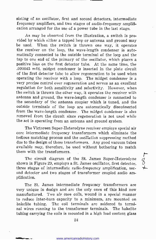
sisting of an oscillator, first and second detectors, intermediate frequency amplifiers, and two stages of audio -frequency amplifi- cation arranged for the use of a power tube in the last stage.
As may be observed from the illustration, a switch is pro- vided by which either a tapped loop or antenna and ground may be used. When the switch is thrown one way, it operates the receiver on the loop, the wave -length condenser is auto- matically connected to the outside terminal of the loop and the tap to one end of the primary of the oscillator, which places a positive bias on the first detector tube. At the same time, the .000045 mfd. midget condenser is inserted in the plate circuit of the first detector tube to allow regeneration to be used when operating the receiver with a loop. The midget condenser is a very precise control over regeneration and serves as an excellent regulation for both sensitivity and selectivity. However, when the switch is thrown the other way, it operates the receiver with antenna and ground, the wave -length condenser is connected to the secondary of the antenna coupler which is tuned, and the outside terminals of the loop are automatically disconnected from the wave -length condenser. The midget condenser is also removed from the circuit since regeneration is not used while the set is operating from an antenna and ground system.
The Victoreen Super -Heterodyne receiver employs special air core intermediate frequency transformers which eliminate the tedious matching process and the oscillation suppressing method due to the design of these transformers. Any good vacuum tubes available may, therefore, be used without bothering to match them with the transformers.
The circuit diagram of the St. James Super -Heterodyne shown in Figure 29, employs a St. James oscillator, first detector, three stages of intermediate radio -frequency amplification, sec- ond detector and two stages of transformer coupled audio am- plification.
The St. James intermediate frequency transformers are very unique in design and are the only ones of this kind now manufactured. Two air core coils, wound in a special manner to reduce inter -turn capacity to a minimum, are mounted on bakelite tubing. The coil terminals are soldered to termi- nal wires running to the transformer terminals. The bakelite tubing carrying the coils is mounted in a high lead content glass
24
www.americanradiohistory.com

www.americanradiohistory.com

casing, the coils are then completely dehydrated by the repeated addition and subtraction of the dehydrated air. When delicate electrical tests prove that the last possible vestige of moisture is removed, the transformers are then sealed.
Figure 30 shows the circuit diagram of the H F L "Master - tone" Super -Heterodyne. This receiver was designed by the High Frequency Laboratories to take advantage of the amplifying ability of the -24 screen grid tube.
The Nine -in -Line Super -Heterodyne is shown in Figure 31. The oscillator and two detector tubes are operated with a com- mon rheostat. This arrangement creates an additional helpful tuning control for lower wave signals when the oscillator dial might tune too sharply. The arrangement of the tubes from left to right is as follows: Oscillator 201-A, first detector 201-A, four intermediate frequency WX-12, second detector 201-A, first audio 201-A, and second audio UX-112.
From an inspection of the schematic diagram, it will be seen that there has been incorporated in this receiver two air core intermediate frequency transformers (filters) instead of the usual one. It is found that the passage of highly amplified signals through a second air core transformer improves selec- tivity to a marked degree.
However, more than three stages of air core intermediate frequency amplification tend to oscillate and cause distortion on the higher wave -lengths. Now this oscillating condition can be remedied by proper shielding or by placing the transformers at a sufficient distance apart. The air core transformers of this re- ceiver are placed at an angle of 90 degrees to the iron core trans- formers so that their fields will not interfere with those of the latter. There are thus a total of four stages of intermediate frequency amplification in the combination.
The circuit diagram of the new World's Record Super - Heterodyne 10 is shown in Figure 32. This receiver is designed for operation with a short indoor or outdoor antenna of about 20 or 30 feet over-all length, a feature which contributes ma- terially to the selectivity of the receiver.
Considering the circuit in its respective divisions, we find first, two tubes devoted to radio -frequency amplification, a first detector and oscillator, three stages of intermediate frequency amplification, a second detector and two stages of audio -fre- quency amplification. The output of the set is fed to the loud -
26
7'
www.americanradiohistory.com

G
3
Z//X/7
r.vIrior
!""""Y. Y 1
o oto'reet
r/OZX/7
V V
v S3ddNri/vl ----- h ° -N.w-menz
ó\0.0909QQ`
ZOO
130 .-.a
h \`Q400000 i _
Z/XM-J7
Y
iLW001/1
«MT, .
Z/XM-17
h;YllOOQ(V 'VITO
Z/XM-J/
Ñe^1;e04400, AVOWS
Z/XM-17
?\00çn7+( l ,,(t)000,3,00..? J
}
O!N
y 7rJHSrXX/- p b v v .
f. '1/O1r77/91"O S7i7o 3N
f
drl II'llNl7
d007
-2t711r77/OR7
IMO
0 aE = U
3m Y N -a
C ;
z c o
-p U
L cog
L m os - « vo Ñ W
7 d W j W L
O« >v t
o 1:3
O C O U Ul
O W
W d
LY« w Y L W m` .0 - O
2ó _
W
o; E E o L - UmÑ
W
Q L
u .. W c W
-c UL « y U
-a Y cm Ó á E6y y _Y
ó >.
nvD -Y W
qlmy a >
C_ Ñ JU p w cWc
vr o C« Z c
I s o
;7« .,
- 1.,c co., L C O
www.americanradiohistory.com

www.americanradiohistory.com

speaker through an output transformer used in the plate circuit of the last tube to isolate the direct potential from the loud- speaker winding.
The success you have with this type of receiver lies prin- cipally in the efficiency and perfect matching of the intermediate frequency transformers.
It is impossible to say what a receiving set will do in a given location, especially in cities, there being too many factors in- volved to permit any broad and sweeping claims to be made. However, if any of these receiving circuits are properly assem- bled and adjusted and the receiver built with the best parts obtainable it will give very good results.
TEST QUESTIONS
Number your Answer Sheet 23-2 and add your Student Number.
No. 1. Name the five classifications of receiving circuits.
No. 2. What is the chief trouble with reflex amplification circuits ?
No. 3. What is the disadvantage of stabilizing a set by placing a resistance in the grid circuits?
No. 4. Draw a diagram illustrating a circuit in which the set is stabilized by the plate -resistance method.
No. 5. What is the purpose of condensers Cl and C2 in the Loftin -White circuit, part of which is illustrated in Figure 17?
No. 6. What is the chief disadvantage in using regeneration to secure radio -frequency amplification?
No. 7. Draw the circuit diagram of the Browning -Drake receiver.
Na 8. How many stages of intermediate radio -frequency amplification are in the St. James Super -Heterodyne?
Nc. 9. Which tube in Figure 31 acts as the second detector?
No. 10. What is the advantage of putting two stages of tuned radio frequency in front of the first detector?
www.americanradiohistory.com

www.americanradiohistory.com


![NRI Housingloanform[1]](https://img.pdfslide.us/doc/110x75/577cd5241a28ab9e7899fdd0/nri-housingloanform1.jpg)


![[NRI] Report](https://img.pdfslide.us/doc/110x75/568c3c231a28ab0235acd82c/nri-report-56f2c44cdd788.jpg)