Embed Size (px)
Citation preview

NRG-22488/11.106369 rev. 1 Confidential 3/47
Contents
Summary 4
1 Introduction 6
1.1 Framework 6
1.2 Approach 8
1.3 Outline 11
2 Scope 12
2.1 Criteria for Scope of Components 12
2.2 Components within the Scope 13
2.3 Component Locations within the Scope 14
2.4 Comparison of Scope 18
3 Methodical Review Fatigue Analyses 19
3.1 Approach 19
3.1.1 Evaluation Criteria 20
3.1.2 Load Cases Used in the Analyses 22
3.1.3 Calculation Methods for the Usage Factor 24
3.1.4 Component Modifications 24
3.2 Review and Results 25
3.3 Results of Methodical Review 27
4 International Developments and Experiences 28
4.1 Environmentally-Assisted Fatigue 28
4.2 High-Cycle Thermal Fatigue 30
4.3 New ASME Fatigue Design Curve 30
4.4 Results International Developments and Experiences 32
5 Status of Fatigue for 9 Remaining Locations 33
6 Conclusions and Recommendations 36
6.1 Conclusions 36
6.2 Recommendations 37
Abbreviations 38

4/47 Confidential NRG-22488/11.106369 rev. 1
Summary
Nuclear power plant (NPP) Borssele is in operation since 1973. In the framework of the long-term
operation (LTO) of NPP Borssele until 2034, the integrity of the safety relevant structures and
components (SCs) in terms of physical ageing has to be demonstrated for the years beyond 2013. One of
the ageing effects important to manage for safe operation of the NPP is fatigue. In the current report the
LTO demonstration of fatigue TLAAs is presented for the license change application.
First, the scope of fatigue relevant locations is determined. In order to define a complete set of locations
requiring fatigue assessments, a survey is performed independently of the existing fatigue analyses
available in the design documentation of NPP Borssele. The scope is determined by means of criteria,
which are in line with the scoping criteria for the Ageing Management Review (AMR) and the break
preclusion concept. The components and locations are determined based on engineering judgement and
literature on international experience. The components and locations within the scope are subsequently
placed in perspective by a comparison to existing analyses, FAMOS measurement locations, US
regulations and a comparable German NPP.
Then, the locations within the scope are assessed by means of a methodical review. In the review the
loads, calculation methods and component modifications are addressed. Within the review the projected
number of load cycles is used to determine a cumulative usage factor representing 2034 (CUF2034). By
this method CUF2034<1 can be determined for all locations except six. Besides this, for three locations the
threshold for environmental fatigue is exceeded. It is recommended to perform further assessment for
these nine locations before the end of 2013 to prove that adequate safety margins against crack initiation
by fatigue are in place also during LTO.
Finally, international experience issues are reviewed. An overview is presented of the different
approaches adopted worldwide (e.g. in the US and Germany) to manage environmentally-assisted fatigue.
Also, an overview is given of high-cycle thermal fatigue cracking events at various NPPs in the world.
Based on the information available in the incident reporting and the ageing management database of NPP
Borssele, it is concluded that none of these events is applicable to NPP Borssele. Finally, the applicability
of the new fatigue design curve for austenitic stainless steels (ASME Boiler and Pressure Vessel Code
2009b Addenda) is discussed. The new fatigue design curve for austenitic stainless steels was derived for
a different set of materials than the fatigue design curve that is mentioned in the ASME Boiler and

NRG-22488/11.106369 rev. 1 Confidential 5/47
Pressure Vessel Code until 2007 and KTA. At the moment, there is no reason to take into account this
new curve for austenitic stainless steels in NPP Borssele.
Based on the assessment several recommendations are given for the fatigue TLAAs of NPP Borssele:
• It is recommended to perform further assessment for six locations before the end of 2013 to prove
that adequate safety margins against crack initiation by fatigue are in place also during LTO:
o Secondary outlet nozzle (steam), component location 2.8;
o TJ/YA nozzle injection, component location 5.2;
o Nozzle of surge line at main coolant line, component location 6.2;
o Nozzle of surge line at pressurizer, component location 6.3;
o Spray nozzles of the auxiliary spray line TA-hot, component location 7.3 (see [89]). The
analysis results can be used to look for the possibilities to change operation conditions to
lower the fatigue loads resulting in a lower CUF;
o Spray nozzles of the spray lines, component location 7.4 (see [90]).
• Address environmentally assisted fatigue according to renewed KTA insights in the further
assessment of component locations which have higher usage factors than the threshold. In this
framework, further assessment of three locations is recommended before the end of 2013:
o TA/YA nozzles, component location 5.1;
o Surge line, component location 6.1;
o Nozzles of the double T-junction, component location 8.2.
It is also recommended to use this procedure in the assessment of the six locations mentioned
above;
• Update the load catalogue and load specifications after 5 cycles of FAMOS and revalidate the
fatigue analyses that where required by this update;
• Keep following international developments, in particular high cycle thermal fatigue and
environmentally assisted fatigue.
For the 9 locations which require further assessment it is shown that for the short term (upcoming years)
no crack initiation due to fatigue is expected.
With this assessment and the follow-up of the recommendations a sound basis is given for the prevention
of crack initiation by fatigue for the period of LTO.
6/47 Confidential NRG-22488/11.106369 rev. 1
1 Introduction
1.1 Framework
Nuclear power plant (NPP) Borssele is in operation since 1973. In the framework of the long-term
operation (LTO) of NPP Borssele until 2034, the integrity of the safety relevant structures and
components (SCs) in terms of physical ageing has to be demonstrated for the years beyond 2013.
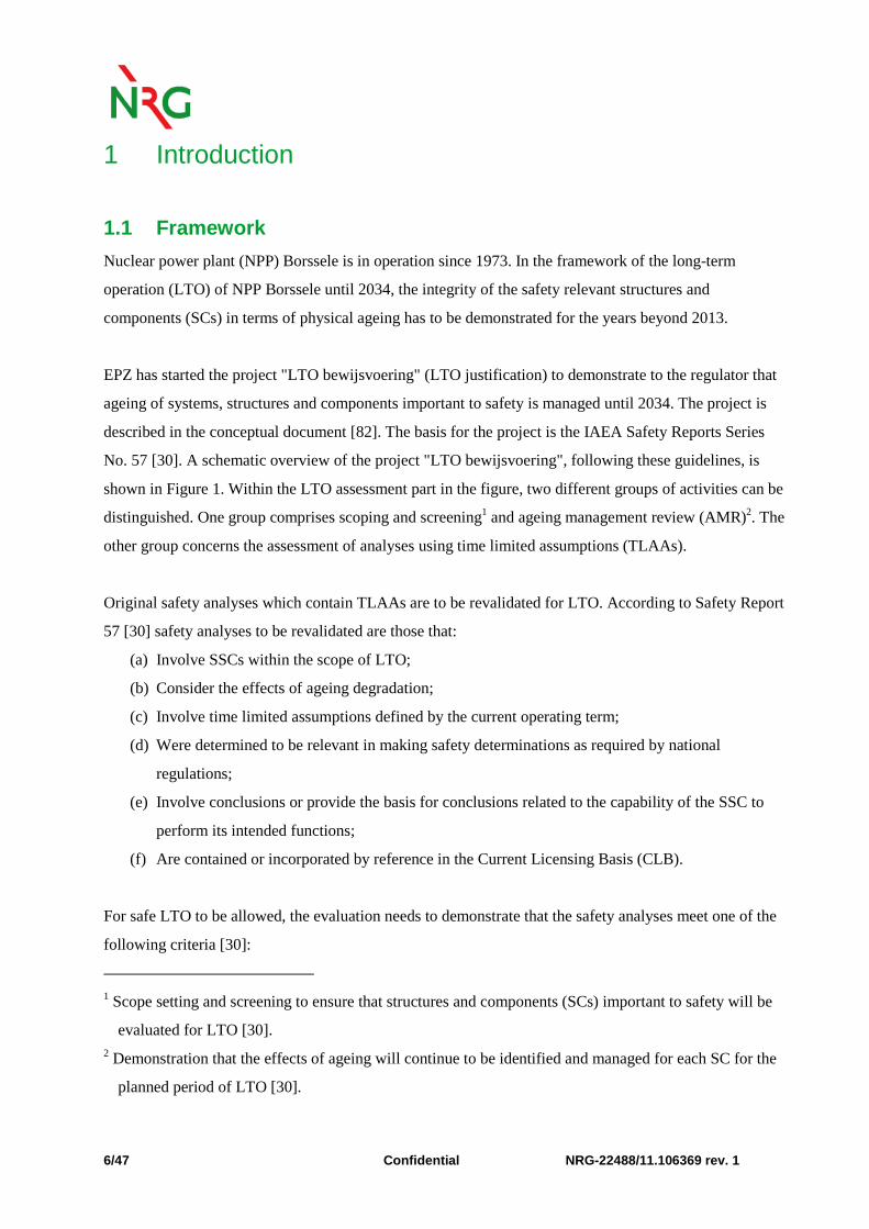
EPZ has started the project "LTO bewijsvoering" (LTO justification) to demonstrate to the regulator that
ageing of systems, structures and components important to safety is managed until 2034. The project is
described in the conceptual document [82]. The basis for the project is the IAEA Safety Reports Series
No. 57 [30]. A schematic overview of the project "LTO bewijsvoering", following these guidelines, is
shown in Figure 1. Within the LTO assessment part in the figure, two different groups of activities can be
distinguished. One group comprises scoping and screening1 and ageing management review (AMR)2. The
other group concerns the assessment of analyses using time limited assumptions (TLAAs).
Original safety analyses which contain TLAAs are to be revalidated for LTO. According to Safety Report
57 [30] safety analyses to be revalidated are those that:
(a) Involve SSCs within the scope of LTO;
(b) Consider the effects of ageing degradation;
(c) Involve time limited assumptions defined by the current operating term;
(d) Were determined to be relevant in making safety determinations as required by national
regulations;
(e) Involve conclusions or provide the basis for conclusions related to the capability of the SSC to
perform its intended functions;
(f) Are contained or incorporated by reference in the Current Licensing Basis (CLB).
For safe LTO to be allowed, the evaluation needs to demonstrate that the safety analyses meet one of the
following criteria [30]:
1 Scope setting and screening to ensure that structures and components (SCs) important to safety will be
evaluated for LTO [30]. 2 Demonstration that the effects of ageing will continue to be identified and managed for each SC for the
planned period of LTO [30].
NRG-22488/11.106369 rev. 1 Confidential 7/47
(i) The analysis remains valid for the intended period of LTO;
(ii) The analysis has been projected to the end of the intended period of LTO;
(iii) The effects of ageing on the intended functions of the structure or component will be
adequately managed for the intended period of LTO.
Fatigue is one of the ageing mechanisms for which TLAAs are applicable and is therefore identified as a
TLAA issue in “LTO Bewijsvoering” [82], see Figure 1. Fatigue is the progressive and localized
structural damage that occurs when a material is subjected to cyclic loadings. In the design phase, fatigue
analyses were performed for several components of NPP Borssele. Most of these analyses in the current
safety report are based upon operation until 2014. After 2013, these analyses are formally no longer valid
and should therefore be updated or different measures have to be taken.
The goal of the current document is to describe the LTO demonstration of fatigue TLAAs until 2034 (red
boxes in Figure 1) in order to cover fatigue in the LTO licence change application. The three criteria for
TLAAs mentioned above are applied in the demonstration. In particular, the conservatism in the load
cycles will be determined and used to demonstrate that crack initiation due to fatigue will not occur.
Figure 1 Schematic overview of LTO assessment of NPP Borssele

8/47 Confidential NRG-22488/11.106369 rev. 1
1.2 Approach
In the design phase of NPP Borssele and during modifications of the plant, fatigue analyses with time
limited assumptions were made for certain safety important components. For these components it was
proven that the fatigue cumulative usage factor (CUF) is below 1.0 for operation until the end of 2013,
based on conservative assumptions on the number of load cycles and stress ranges of transients. For the
number of transients a load catalogue was specified. By monitoring the number of transients and
comparing the actual number with the assumed number of transients in the load catalogue, the validity of
the assumptions on the number of transients is checked on a yearly basis.
Revalidation of the existing analyses for LTO can in principle be done by showing that the assumed
number of load cycles and stress ranges of transients in the original analyses will not be exceeded during
the LTO period. However, during the last decade worldwide discussions emerged on the conservatism of
the existing fatigue design curves and particularly the influence of the coolant environment on the fatigue
life (environmental fatigue). Although this issue is still disputed by experts in the world and only based
on laboratory tests, procedures were developed in the USA and Japan to address environmental fatigue.
New design curves were developed together and correction factors to account for environmental fatigue.
Depending on several parameters the influence of a water environment can be substantial in theory.
The goal of the fatigue project is to demonstrate that for all components important to safety adequate
safety margins against crack initiation by fatigue are in place at every moment during operation until
2034, taking into consideration the possible influence of environmental effects.
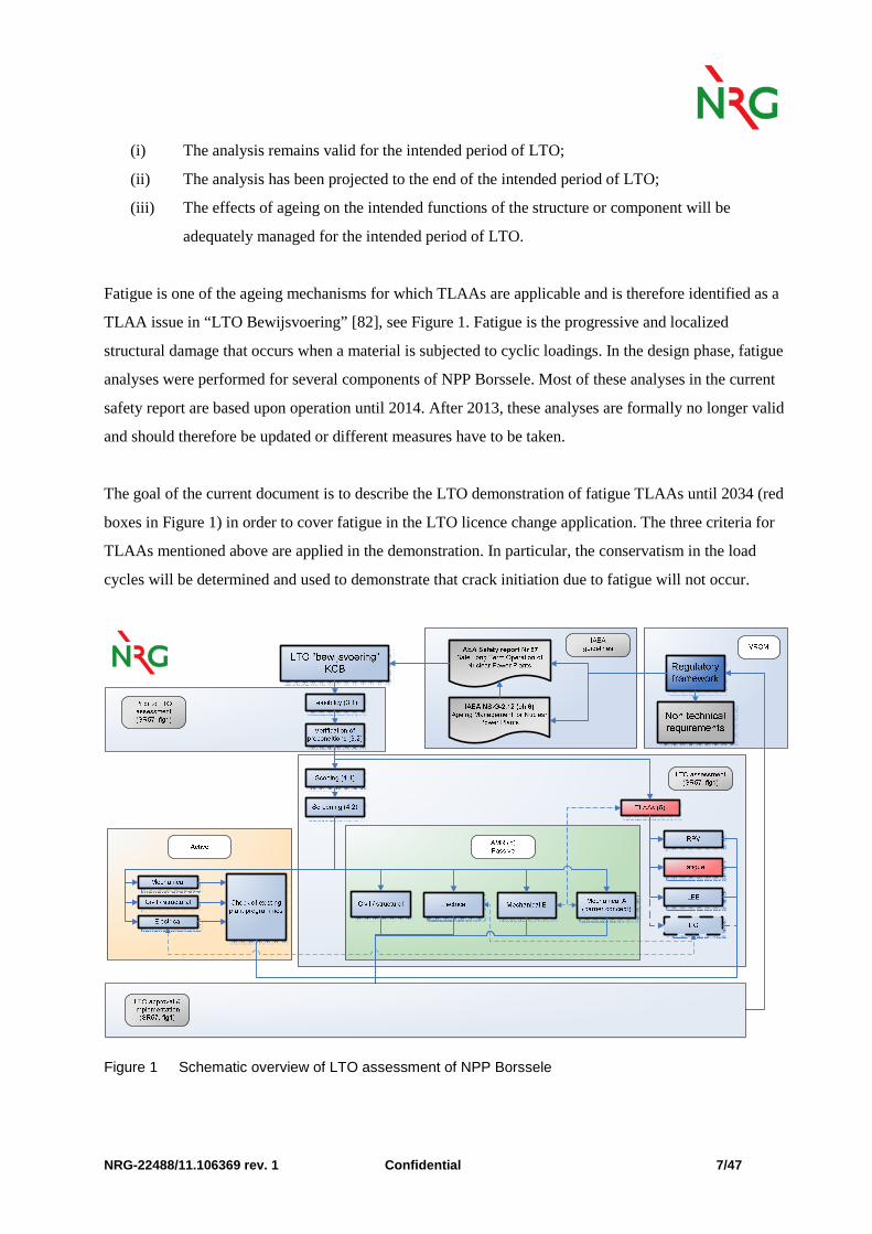
In order to achieve this goal, a number of activities is carried out. The project with its activities and a
timeline is shown in Figure 2 and described below:
Thermal Load monitoring / load specification
As mentioned above the calculated cumulative usage factors (CUF) in the original analyses are based on
conservative assumptions on numbers of load cycles and stress ranges of transients. To be able to
revalidate the fatigue analyses for LTO including the incorporation of possible environmental influence,
best estimate calculations of the fatigue life are needed including realistic assumptions on the (thermal)
loads. For this reason during the yearly outage in 2010 the AREVA FAMOS system was implemented
which is able to precisely monitor thermal loads including stratification. The monitoring locations are
based on an assessment of the thermal loads (the FAMOS manual [67]). Based on the experience with

NRG-22488/11.106369 rev. 1 Confidential 9/47
FAMOS and similar systems in German NPPs it is expected that new representative load specifications
can be produced with FAMOS after 5 cycles. After these 5 cycles of FAMOS a new load catalogue and
load specifications will be made based on [77] and FAMOS results.
Scoping TLAA Fatigue
Although NPP Borssele has a set of existing Fatigue TLAAs it was decided for LTO to perform an
independent scoping survey to determine for which component locations fatigue assessments should be
necessary. This survey was based on international practice and engineering judgement. The scope for
which revalidation is foreseen consists of the newly determined component locations complemented with
the component locations for which fatigue TLAAs were available.
Demonstration on safety margins for LTO license change application
For all component locations in the scope, a systematic review is performed on the available fatigue
assessments. Based on a comparison of the number of transients in the analysis with the projected number
of transients in 2034 a CUF2034 is calculated for every in-scope component location. Environmental
fatigue is addressed by following the newly proposed KTA rules on environmental fatigue in which
awareness threshold values for ferritic and austenitic steel are given. For component locations in contact
with water and usage factors above the awareness threshold values further measures are specified.
For all component locations for which a CUF2034 below 1.0 cannot be delivered with this assessment
(based on the original analyses) or for which the usage factor is above the KTA environmental fatigue
threshold values, short term assessments are delivered which prove the safety margins on fatigue crack
initiation for these locations. For the relevant locations further assessments are delivered before the end of
2013.
In the assessment also the management of high cycle thermal fatigue is studied. Worldwide some NPPs
experienced fatigue cracks because of high cycle thermal fatigue. Those events are evaluated at NPP
Borssele and in this assessment an overview is given. The applicability of the new fatigue design curve
for austenitic stainless steels (ASME Boiler and Pressure Vessel Code 2009b Addenda) is discussed. The
impact of the new ASME design fatigue curve on the stainless steels in NPP Borssele is investigated.
Demonstration including environmental fatigue and fatigue monitoring during LTO
After 5 cycles of measuring new load specifications come available for thermal transients. Based on the
new load specifications it is foreseen to perform new fatigue calculations including environmental effects,
10/47 Confidential NRG-22488/11.106369 rev. 1
if applicable. About the influence of the water environment discussion is ongoing. Different approaches
can be seen to account for environmental fatigue.
After the determination of best estimate usage factors (including environmental effects) all relevant
locations will be continuously monitored for the period of LTO by FAMOS. For all locations in the scope
a yearly update of the fatigue usage will be provided. In some cases it might be possible to modify
existing operation procedures to lower the fatigue loads if this is desirable based on FAMOS monitoring.
With the aforementioned approach a sound basis is given for the prevention of crack initiation by fatigue
for the period of LTO.
Figure 2 LTO demonstration and projects in the framework of fatigue at NPP Borssele
NRG-22488/11.106369 rev. 1 Confidential 11/47
1.3 Outline
The outline of the current report is structured as described below.
First the scope is presented. In order to define a complete set of fatigue locations requiring fatigue
assessments, a survey is performed independently of the existing fatigue analyses available in the design
documentation of NPP Borssele. Based on international practice and guidelines and engineering
judgement, the set of component locations requiring fatigue assessments is determined. The process to
determine the scope and the final scope is described in chapter 2.
Then the current status of the fatigue analyses is assessed in the framework of LTO. For each of the
existing fatigue analyses, it is demonstrated whether the assessment criteria for cyclic loading from
KTA/ASME are satisfied until 2034. The conservatisms in the analyses are assessed to support integrity
demonstration. For the assessment of the analyses, the load cases and numbers of cycles occurred in
reality are taken into account. This results in a fatigue assessment and CUF2034 for every component
location in the scope. The process and outcomes are described in chapter 3.
Subsequently, international developments and experiences are reviewed. State-of-the-art knowledge and
practice regarding relevant insights and developments in the fields of environmentally-assisted fatigue
and high-cycle thermal fatigue are described in chapter 4.
Chapter 5 shows that for the short term no crack initiation due to fatigue is expected for all component
locations.
Finally the conclusions and recommendations are described in chapter 6.
12/47 Confidential NRG-22488/11.106369 rev. 1
2 Scope
In this chapter, the determination of the scope for the assessment of fatigue analyses for NPP Borssele is
presented. In order to define a complete set of fatigue locations requiring fatigue assessments, a survey is
performed independently of the existing fatigue analyses available in the design documentation of NPP
Borssele. The criteria which are used for the scope of components are presented in section 2.1. Then the
resulting scope of components is presented in section 2.2. Further detailing of the locations within these
components based on engineering judgement and international experience is shown in section 2.3.
Finally, the resulting scope is placed in perspective by a comparison to existing analyses, FAMOS, US-
regulations and a comparable German power plant in section 2.4.
This chapter is based on the detailed description of the scope and the comparison with international
practice in the scoping report for fatigue TLAAs [84].
2.1 Criteria for Scope of Components
The LTO demonstration of fatigue TLAAs is part of the LTO assessment of Borssele NPP. Since the
Ageing Management Review (AMR) is closely related to the fatigue TLAAs, the scope of components
for fatigue is aligned with the AMR scope. The IAEA Safety Reports Series No. 57 [30] provides general
criteria, which serve as a basis for scoping and screening for LTO. The basic definition for Systems,
Structures and Components (SSCs) within the scope of LTO is based on their safety functions [30]. In
the scoping document for LTO of NPP Borssele [31], this basic definition is worked out in more detail
and results in the following three safety categories:
• Safety category S1 – Main components of the reactor coolant system;
• Safety category S2 – SSCs important to safety;
• Safety category S3 – SSCs whose failure may impact upon the safety functions specified in
categories S1 and S2.
In accordance with US regulation procedures for screening [30], only passive SCs are considered for the
AMR. To determine the fatigue TLAA scope a part of the above AMR scope is used. All S1 SCs are in
the scope because they contain components of the reactor coolants systems which are not allowed to fail.
This scope is extended with S2 components which are directly connected to the primary system or which
NRG-22488/11.106369 rev. 1 Confidential 13/47
are part of the break preclusion concept [32]. The two safety based criteria that are used for determination
of the scope of fatigue TLAAs are defined as follows:
1. Safety category S1 components + piping attached to these components until the second valve.
2. Components of the secondary system directly connected to components of the primary system +
feed water piping and main steam piping belonging to the break preclusion concept.
2.2 Components within the Scope
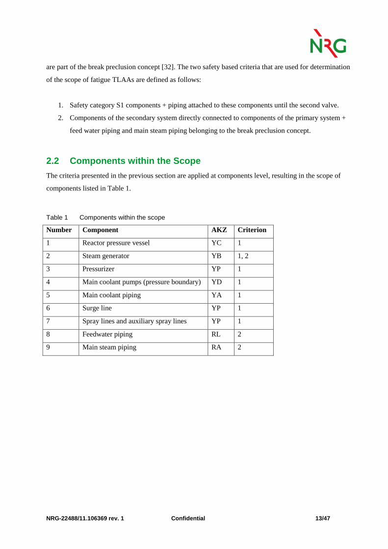
The criteria presented in the previous section are applied at components level, resulting in the scope of
components listed in Table 1.
Table 1 Components within the scope
Number Component AKZ Criterion
1 Reactor pressure vessel YC 1
2 Steam generator YB 1, 2
3 Pressurizer YP 1
4 Main coolant pumps (pressure boundary) YD 1
5 Main coolant piping YA 1
6 Surge line YP 1
7 Spray lines and auxiliary spray lines YP 1
8 Feedwater piping RL 2
9 Main steam piping RA 2

14/47 Confidential NRG-22488/11.106369 rev. 1
2.3 Component Locations within the Scope
Further detailing of the scope is performed by selecting locations in the components. These component
locations are identified by engineering judgement and international experience. Documents with specific
information of components of NPP Borssele as well as international guidelines, working group
documents and literature have been used as information sources:
• IAEA-TECDOCs [33] to [39];
• SSC reports of 10 EVA [40] to [53];
• NUREG 1801 GALL [54];
• NUREG/CR-6260 [56];
• Shah and MacDonald [57];
• ASME Boiler and Pressure Vessel code [58];
• KTA standards [59] to [64];
• RE-L specifications [65].
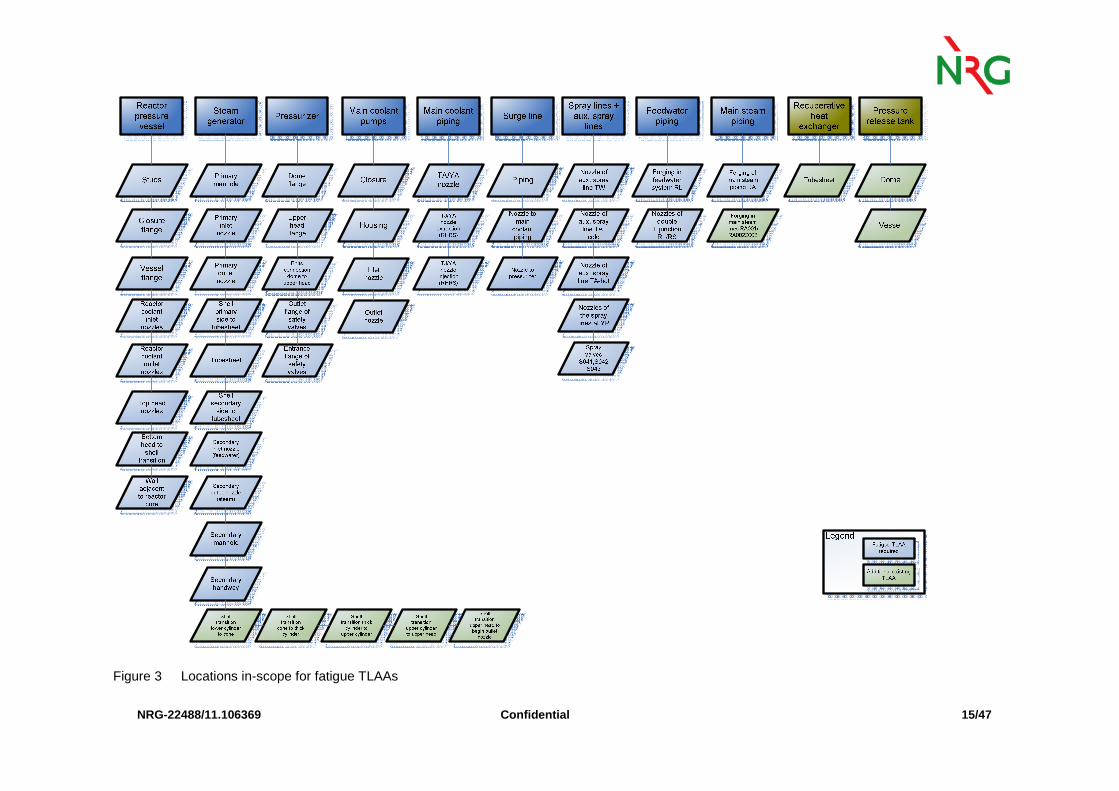
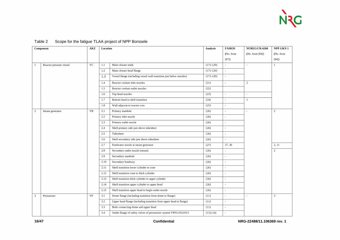
Per component a number of locations is selected. The resulting scope of locations is shown in Figure 3
and Table 2, where per component the relevant locations are identified. Locations with existing fatigue
TLAAs are added to the scope, in line with US nuclear guidance on license renewal NEI [68]. These
locations are shown in green in Figure 3. Table 2 shows the locations and the corresponding analysis
reference number in a separate column. The last three columns in the table refer to the comparison of the
scope with FAMOS and international experience, which is discussed in the next section.
NRG-22488/11.106369 Confidentia l
15/47
Figure 3 Locations in-scope for fatigue TLAAs
Confidential NR G-22488/11.106369 rev. 1 16/47
Table 2 Scope for the fatigue TLAA project of NPP Borssele
Component AKZ Location Analysis FAMOS
(No. from
[67])
NUREG/CR-6260
(No. from [84])
NPP GKN 1
(No. from
[84])
1 Reactor pressure vessel YC 1.1 Main closure studs {17}-{20} - - 1
1.2 Main closure head flange {17}-{20} -
1.3 Vessel flange (including vessel wall transition just below nozzles) {17}-{20} -
1.4 Reactor coolant inlet nozzles {21} - 2
1.5 Reactor coolant outlet nozzles {22}
1.6 Top head nozzles {23} - -
1.7 Bottom head to shell transition {24} - 1
1.8 Wall adjacent to reactor core {25} -
2 Steam generator YB 2.1 Primary manhole {26} - - 2
2.2 Primary inlet nozzle {26} -
2.3 Primary outlet nozzle {26} -
2.4 Shell primary side just above tubesheet {26} -
2.5 Tubesheet {26} -
2.6 Shell secondary side just above tubesheet {26} -
2.7 Feedwater nozzle at steam generator {27} 27, 30 2, 11
2.8 Secondary outlet nozzle (steam) {26} - 2
2.9 Secondary manhole {26} -
2.10 Secondary handway {26} -
2.11 Shell transition lower cylinder to cone {26} -
2.12 Shell transition cone to thick cylinder {26} -
2.13 Shell transition thick cylinder to upper cylinder {26} -
2.14 Shell transition upper cylinder to upper head {26} -
2.15 Shell transition upper head to begin outlet nozzle {26} -
3 Pressurizer YP 3.1 Dome flange (including transition from dome to flange) {11} - - 3
3.2 Upper head flange (including transition from upper head to flange) {11} -
3.3 Bolts connecting dome and upper head {11} -
3.4 Outlet flange of safety valves of pressurizer system YP011/012/013 {13}{14} -

NRG-22488/11.106369 rev. 1 Confid ential 17/47
3.5 Entrance flange of safety valves of pressurizer system YP011/012/013 {14} -
4 Main coolant pumps YD 4.1 Housing {29} - - 4
4.2 Closure {29} -
4.3 Inlet nozzle {29} -
4.4 Outlet nozzle ({29}) -
5 Main coolant piping YA 5.1 TA/YA nozzle {16} 15, 17 4 5, 8
5.2 TJ/YA nozzle (injection) ({28}) 22, 23 6 5, 9
5.3 TJ/YA nozzle (extraction) {28} 2, 24, 25 5
6 Surge line YP 6.1 Surge line piping {5} 2, 3, 6, 8 3 6
6.2 Nozzle of surge line at main coolant line {5}* -
6.3 Nozzle of surge line at pressurizer {5}* -
7 Spray lines and auxiliary spray lines YP 7.1 Spray nozzles of the auxiliary spray line TW {6} - - 7
7.2 Spray nozzles of the auxiliary spray line TA-cold {7} -
7.3 Spray nozzles of the auxiliary spray line TA-hot {8} 13
7.4 Spray nozzles of the spray lines (3x) {9} 9, 12
7.5 Spray valves YP0001S041/042/043 {12} 9, 12
8 Feedwater piping RL 8.1 Forging of the feedwater system RL {2} - - 11
8.2 Nozzles of double T-junction (RL/RS) {4} 28, 29, 32
9 Main steam piping RA 9.1 Forging of the main steam piping RA {3} - - 12
9.2 Forging in the main steam lines RA0001/RA002Z002 {15} -
10 Recuperative heat exchanger TA 10.1 Tubesheets of recuperative heat exchanger {1} 18, 19, 20, 21 - 8
11 Pressure release tank YP 11.1 Dome {10} - - -
11.2 Vessel -
* Nozzles are included in the model as straight pipe elements.
Confidential NRG-22488/11.106369 rev. 1 18/47
2.4 Comparison of Scope
In order to place the selected scope for NPP Borssele in perspective a comparison is made to existing
fatigue analyses, FAMOS locations and international practice. The comparison with FAMOS [67],
NUREG/CR-6260 [56] and the German NPP Neckarwestheim [66] is shown in Table 2 and is described
in more detail in [84].
Existing analyses
The existing analyses for NPP Borssele are listed in the column analysis. The comparison shows that all
locations in scope are covered by an existing analysis, except the nozzles of surge line. These will be
discussed in the next chapter. The locations added based on existing fatigue analyses are: tubesheet of the
recuperative heat exchanger, dome and vessel of the pressure release tank, forging in the main steam
lines, entrance flange of the safety valves and five shell transitions of the steam generator shell. These
locations are shown in green in Figure 3.
FAMOS
All FAMOS measurement locations are within the scope as shown in Table 2. With these measurements
more detailed information on the actual temperatures and fluctuation in the system can be determined in
three to five cycles of operation. The comparison to the scope is shown in Table 2.
US regulations
Compared to the guidelines followed in the US (NUREG/CR-6260 [56]), the scope of NPP Borssele is
more extensive. In addition to the NUREG/CR-6260, EPZ takes into account the pressurizer, steam
generator, main coolant pumps, (auxiliary) spray lines and part of the secondary piping in the scope
outcome of the assessment, see Table 2.
Neckarwestheim NPP
Comparison to international practice shows that the scope of NPP Borssele is in line with international
fatigue scopes at a comparable NPP. In Table 2 it is shown that the scope of Borssele is in line with the
scope of the nuclear power plant of Neckarwestheim 1 (GKN1) [66]. GKN1 is a KWU-Siemens NPP,
similar to NPP Borssele, which was also built in the early ‘70s.

NRG-22488/11.106369 rev. 1 Confidential 19/47
3 Methodical Review Fatigue Analyses
For the fatigue component locations in the scope, as determined in the previous chapter, a methodical
review is performed on the fatigue analyses at these locations. As shown in the previous chapter, a series
of fatigue analyses is made for NPP Borssele during the construction phase and during modifications of
the plant. Depending on the specifications different codes have been used in the analyses. A methodical
review is performed to identify the margins in the analyses for LTO demonstration. The review results in
a determination of the usage factor for the locations in scope for 2034. The results of the methodical
review of the fatigue analyses are reported in detail in the analyses review report for fatigue [85].
The current chapter describes the results of the methodical review. The approach is discussed in section
3.1. The review and results are discussed in section 3.2. The results are presented in section 3.3.
3.1 Approach
The approach for the methodical review consists of a number of steps. These steps are described in four
sub-sections within the current section. The first step consists of a set-up of evaluation criteria, which are
systematically applied to the analyses (sub-section 3.1.1).
From this evaluation several items are deduced relevant for assessment of the analyses up to 2034. These
items are:
• Load cases used in the analysis, leading to a projected number of cycles (sub-section 3.1.2);
• Calculation methods for the usage factor, leading to a consistent fatigue assessment method
according to the ASME and KTA methods (sub-section 3.1.3);
• Component modifications, leading to a correct extrapolation of number of cycles for components
replaced in the modification of 1997 (sub-section 3.1.4).
These steps are summarized in the current section. For more details is referred to the analyses review
report for fatigue [85].

Confidential NRG-22488/11.106369 rev. 1 20/47
3.1.1 Evaluation Criteria
The existing fatigue analyses are assessed until 2034. For every location in the scope the fatigue analysis
is assessed on the items listed in Table 3: general data, input data, analysis method, loads, fatigue
analysis, conservatism/margins, relevant operating experience, FAMOS and environment. Each of these
items is systematically addressed for every analysis. The results are presented in tables in [85] and used as
a basis for assessment of the analysis until 2034.

NRG-22488/11.106369 rev. 1 Confidential 21/47
Table 3 Assessment items and criteria for the existing fatigue analyses
Assessment item Sub item Criterion General data 1 EPZ document number.
2 Original document number. 3 Supplier. 4 Title. 5 Year. 6 Component description.
Input data Geometry Is the geometry representing the actual status in the power plant? Checked by EPZ. Within the current scope, there was no check for local dimensions based on drawings.
Material properties Type specification of the material. Is the material type representing the actual status in the power plant? Checked by EPZ. Are the material specifications mentioned in the report? Within the current scope, there was no check for the values mentioned and the properties given in the supplier data. Are the material specifications used temperature dependent or constant?
Boundary conditions thermal analysis
What is the accuracy of the heat transfer coefficient? What is the accuracy of the other thermal boundary conditions? Within the current scope, there was no check of underlying references.
Boundary conditions mechanical analysis
What is the accuracy of the mechanical boundary conditions? Within the current scope, there was no check of underlying references.
Assumptions Note the remarks about assumptions of the analysis. Analysis method 1 Dimensionality of the analysis (1D / 2D / 3D). 2 Analysis method (e.g. analytical / FEM). 3 Type of analysis (thermal / mechanical / fatigue). 4 Name of the software used for each type of thermal / mechanical / fatigue analysis. 5 How detailed is the mesh used for the calculation? 6 Element type specification. 7 Number of years calculated for fatigue. Loads 1 Are the fatigue relevant transients used in the analysis chosen correctly from the load reference (e.g. load
specification)? Checked in cooperation with EPZ.
2 Do the numbers of load cycles in the analysis correspond with the numbers of load cycles in the load reference (e.g. load specification)?
3 Are the transients used for the analysis identical to the transients specified in the load reference (e.g. load specification)?
4 Is the number of load cycles used for the replacing transient correct? 5 Does the replacing transient cover the replaced transients? 6 Is the number of load cycles specified in the analysis larger than the number of load cycles in reality, now and in
2034? The number of load cycles in reality (now and in 2034) has been given by EPZ.
7 Reference for the loads used according to the analysis. 8 Type of load document referred to.
Fatigue analysis 1 The name of the standard / code used including the paragraph number. 2 Are the fatigue relevant locations within the analysis geometry chosen correctly based on engineering judgment? 3 Number of locations considered for fatigue within the analysis geometry. 4 Cumulative usage factor. 5 Location with largest cumulative usage factor.
Conservatism/margins 1 Is there a description of conservatism or margins in the analysis? 2 If yes, give description.
Relevant operating experience
1 Are all transients covered? (database) Checked by EPZ.
2 Are there any inspection findings for this component? Checked by EPZ.
3 Was the component or part of the component replaced during lifetime? 4 If yes, give description of the part and year of replacement. FAMOS Is FAMOS present at / near the component? Environment 1 Is the component in contact with water?
2 If in contact with water, is the material of the component ferrite or austenite? 3 If in contact with water, what is the average water temperature?
Concluding remarks Status / quality of the analysis and recommendations.
Confidential NRG-22488/11.106369 rev. 1 22/47
3.1.2 Load Cases Used in the Analyses
In order to assess the fatigue status at the different in-scope locations for long term operation, the current
number of cycles has to be projected until 2034. A thorough survey is made of the loads used in the
analyses. First, the load references for the existing analyses are reviewed. From these load references a
complete list of applied load cases is made. The different load cases are shown in Table 4 where the
identification numbers are taken from the load catalogue [77]. Subsequently, the number of cycles for
these transients used in the existing analyses is compared to the actual number of cycles counted
(transient report [78]). Finally, for the derivation of the usage factor until 2034 the projected number of
cycles until 2034 will be used. The projected number of cycles is the number of cycles until 2034 that is
expected based on history and engineering judgement. To obtain the projected number of cycles the
counted numbers of cycles from the transient report [78] are extrapolated until 2034. Besides this, the
minimal number of cycles for each transient used in the analyses is derived. The numbers of cycles are
checked for a minimal number of 1 cycle per transient. This means that in case the extrapolated number is
zero, at least one cycle is projected until 2034. In the extrapolation the higher frequency of occurrences of
the load cases in the first two years (1973 and 1974) is taken into account. This period is considered as a
start-up period of the reactor and the corresponding load cases are taken into account separately in the
extrapolation. The equations that are used for extrapolation are defined in detail in [85].
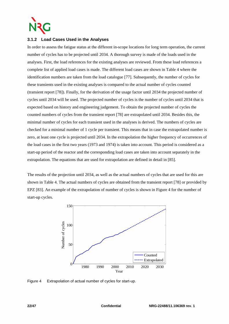
The results of the projection until 2034, as well as the actual numbers of cycles that are used for this are
shown in Table 4. The actual numbers of cycles are obtained from the transient report [78] or provided by
EPZ [83]. An example of the extrapolation of number of cycles is shown in Figure 4 for the number of
start-up cycles.
1980 1990 2000 2010 2020 20300
50
100
150
Year
Num
ber
of c
ycle
s
CountedExtrapolated
Figure 4 Extrapolation of actual number of cycles for start-up.

NRG-22488/11.106369 Confidential
23/47
Table 4 Projected number of cycles until 2034
ID in load catalogue
Load case description Actual number of cycles 1973-2007
Actual number of cycles 1973-1974
Projected number of cycles 1973-2034
Projected number of cycles 1997-2034
Auslegungsfälle Bestimmungsgemäßer Betrieb (1) Normale betriebsfälle NB
2.0 Stationärer Leistungsbetrieb (Teillastverhalten) - - - -
2.1/2.2 An- und Abfahren der Anlage (SU=start-up, SD= shutdown) 86/85 18/17 142/141 78
2.3 Sprungförmige Laständerungen 122 63 170 68
2.4 Rampenförmige Laständerungen 41 17 61 28
2.5 Montagen des Reaktordruckbehälter-Deckel 40 2 71 44
2.6 Zu- und Abschalten einer zweiten HD-Förderpumpe des VRS 1348 - 2388 1507
(2) Anomale Betriebsfälle (AB)
2.10 Reaktorschnellabschaltung RESA 26 6 42 23
2.11 Turbinenschnellschluss (TUSA) oder Lastabwurf (LAW) auf Nulllast bzw. Auf Eigenbedarf 54 9 91 52
2.12 Fehlschließen einer Frischdampf-Absperrarmatur 0 0 2 1
2.13 Ausfall einer Hauptkühlmittelpumpe/Ausfall einer Pumpe (besonders wichtig für Austrittsstutzen wegen Thermoschock hervorgerufen durch Strömungsumkehr)
30 7 49 26
2.14 Störungen in den an die DE anschließenden Speisewassersystemen - - 3 2
2.15 Systemeigene Storungen im VRS mit Auswirkung auf die Komponenten des NDES - - 1 1
2.16 Fehlöffnen eines FDU-Ventils 0 0 2 1
2.17 Hilfssprühen mit dem VRS 0 0 18+ 11+
(3) Prüffälle (PF)
2.20 Druckproben Reaktorkühlsystem 3 1 3* 2*
2.21 Dichtheitsprüfungen Reaktorkühlsystem 0 0 -# -#
2.22 Druckproben DE-Sekundärseite 1 1 1* 1*
2.23/2.23.1/ 2.23.2 Prüfungen der DH-Druckabsicherungseinrichtungen=Sicherheitsventile - - 93 57†
Störfälle
(1) Notfälle (NF)
3.1 Notstromfall 7 - 13 8
3.1.1 Notstromfall mit anschließenden Wiederanfahren in 3.1^ in 3.1^ in 3.1^ in 3.1^
3.1.2 Notstromfall mit Abfahren mit stehenden HKMP auf 120°C in 3.1^ in 3.1^ 1 1
3.2 Turbinenschnellschluss ohne FDU 3 - 5 4
3.2.1 Mit anschließenden Wiederanfahren in 3.2^ in 3.2^ in 3.2^ in 3.2^
3.2.2 Mit Abfahren auf Nulllast-kalt in 3.2^ in 3.2^ in 3.2^ in 3.2^
3.3 Dampferzeuger-Heizrohrleckage 0 0 13 8
3.3.1 Hauptwarmesenke steht zur verfugung 0 0 1 1
3.3.2 und Notstromfall 0 0 1 1
3.4 Ansprechen eines DH-Sicherheitsventils 0 0 1 1
3.5.1 Nicht schließen einer DH-Sicherheitsventils: Bei einer Prüfung 0 0 6 1
3.5.2 Nicht schließen einer DH-Sicherheitsventils: Nach dem Ansprechen, Abfahren auf Nulllast-kalt 0 0 2 1
3.6 Nichtschließen eines FD-Sicherheitsventils 0 0 9 1
3.7 Fehlerhafte Kaltwassereinspeisung in die DE durch das Reservespeisesystem RS 0 0 1 1
3.8 Kleines HKML-Leck 0 0 1 1
3.9 Kleines Sekundärleitungsleck 0 0 3 2
(2) Schadensfälle (SF)
3.10.1 Mittleres Kühlmittel-leck 0 0 1 1
3.10.2 Großes Kühlmittel-leck 0 0 1 1
3.11.1 Mittleres Sekundärleitungs-leck 0 0 1 1
3.11.2 Großes Sekundärleitungs-leck 0 0 1 1
3.12 Bemessungserdbeben 0 0 1 1
(3) Sonderfälle (SoF)
3.15 Betriebstransienten mit Versagen der Reaktorschnellabschaltung (ATWS) 0 0 5 3
3.16 Primärseitiges Druckentlasten und Bespeisen 0 0 1 1
3.17 Sekundärseitiges Druckentlasten und Bespeisen 0 0 1 1
Load case description Actual number of cycles 1973-2007
Actual number of cycles 1973-1974
Projected number of cycles 1973-2034
Projected number of cycles 1997-2034
Load cases used in fatigue analyses, but not mentioned in load catalogue Spülen mit N2 <85 <17 <141 <78
Änderung der Speisewassereintrittstemperatur an der Dampferzeugern 0+ 0+ 3 3
Afkoelen naar nullast koud d.m.v. secundaire veiligheidskleppen Abkühlen auf Nullast kalt mit den Frischdampf-Abblaseregelventilen
0 0 1 1
Notstrombetrieb mit abkühlen auf Nullast nach 6 Stunden 0 0 5 5
Antrieb der Steuerstäbe - - 13650000 12000000
Omschakelen op koude TA-toevoerleiding 0 0 1 1
Leckage eines Druckhaltersicherheitsventils 0 0 1 1
Obtained from transients report [78] Provided by EPZ [83]
* These tests are not performed anymore at NPP Borssele. † The safety valves have been replaced in 1997. This test case is estimated to occur on average 1.5 times per year. + Based on FAMOS measurement data. ^Transient not split (in x.x.1 and x.x.2) in transient report [78]. # These test are not performed at NPP Borssele [77].

Confidential NRG-22488/11.106369 rev. 1 24/47
3.1.3 Calculation Methods for the Usage Factor
The calculation method for the usage factor is described in general terms in the KTA [79] and ASME
Section III [58] code. The terminology in the codes allows for different interpretations. Based on the
interpretation of the codes, the usage factor is calculated in the analyses. The calculation is sometimes
performed manually. However in most cases a computer program is used. Different computer programs
have been developed in time. The consistency of the programs and their calculations methods are
presented in detail in [85] and are summarized in this section.
The used methods in the fatigue analyses are: manual calculations, ANSYS (different versions), ISAAC,
SACRAC NUCON (1974), SACRAC RDM (1971/1972). In order to determine the correctness of the
methods, the methods are compared to the method descriptions in the KTA [79] and ASME Section III
[58] code.
Although differences exist, ANSYS, ISAAC, SACRAC NUCON 1974 are in agreement with the method
description in the design codes. SACRAC RDM 1971/1972 however ignores relevant loadings by only
taking into account the highest stress amplitude within one transient. Therefore, a correction factor is
calculated.
The analyses of the reactor vessel closure flange, inlet nozzles, outlet nozzles, top head nozzles, bottom
head to shell transition, and wall adjacent to reactor core {20}-{25} use the SACRAC RDM 1971/1972
method.
To determine a correction factor for the SACRAC RDM 1971/1972 method, usage factors based on the
SACRAC NUCON 1974 method are recalculated with the SACRAC RDM 1971/1972 method. The usage
factors for the studs of analyses {17}, {18} and {20} are recalculated. From the assessment,
conservatively a correction factor of 4.2 (maximum factor) is determined in [85]. This factor is applied in
the assessment of the analyses which use the SACRAC RDM 1971/1972 method, i.e. {21}-{25}.
3.1.4 Component Modifications
During the lifetime of the reactor, components have been replaced or modified. The replacements or
modifications for the component locations within the scope are summarized in [85]. Fatigue analyses
NRG-22488/11.106369 rev. 1 Confidential 25/47
have been updated during the modification. From [85] the number of years can be identified to be taken
into account until 2034 for a specific component location.
3.2 Review and Results
The analyses for the in-scope locations are reviewed using the approach as presented in the previous
section. The results of the review are presented in [85]. For each analysis the status of the fatigue analysis
is first presented. Then the comparison is made of the projected number of cycles until 2034 and number
of cycles taken into account in the fatigue analysis. The assessment is made, using the projected number
of cycles from Table 4. Finally the integrity until 2034 is represented by means of the new fatigue usage
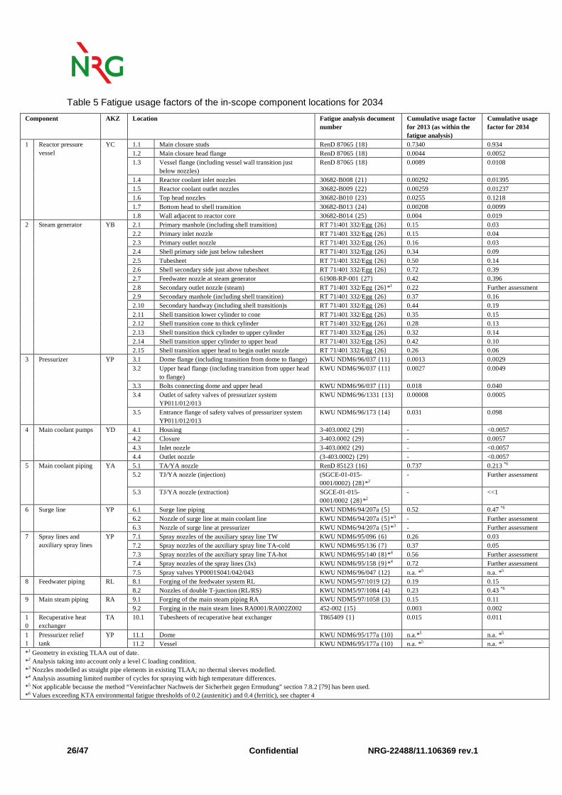
factor in 2034. The result of this systematic review is shown for the in-scope locations in Table 5.
Confidential NRG-22488/11.106369 rev.1 26/47
Table 5 Fatigue usage factors of the in-scope component locations for 2034
Component AKZ Location Fatigue analysis document number
Cumulative usage factor for 2013 (as within the fatigue analysis)
Cumulative usage factor for 2034
1 Reactor pressure vessel
YC 1.1 Main closure studs RenD 87065 {18} 0.7340 0.934 1.2 Main closure head flange RenD 87065 {18} 0.0044 0.0052 1.3 Vessel flange (including vessel wall transition just
below nozzles) RenD 87065 {18} 0.0089 0.0108
1.4 Reactor coolant inlet nozzles 30682-B008 {21} 0.00292 0.01395 1.5 Reactor coolant outlet nozzles 30682-B009 {22} 0.00259 0.01237 1.6 Top head nozzles 30682-B010 {23} 0.0255 0.1218 1.7 Bottom head to shell transition 30682-B013 {24} 0.00208 0.0099 1.8 Wall adjacent to reactor core 30682-B014 {25} 0.004 0.019
2 Steam generator YB 2.1 Primary manhole (including shell transition) RT 71/401 332/Egg {26} 0.15 0.03 2.2 Primary inlet nozzle RT 71/401 332/Egg {26} 0.15 0.04 2.3 Primary outlet nozzle RT 71/401 332/Egg {26} 0.16 0.03 2.4 Shell primary side just below tubesheet RT 71/401 332/Egg {26} 0.34 0.09 2.5 Tubesheet RT 71/401 332/Egg {26} 0.50 0.14 2.6 Shell secondary side just above tubesheet RT 71/401 332/Egg {26} 0.72 0.39 2.7 Feedwater nozzle at steam generator 61908-RP-001 {27} 0.42 0.396 2.8 Secondary outlet nozzle (steam) RT 71/401 332/Egg {26}* 1 0.22 Further assessment 2.9 Secondary manhole (including shell transition) RT 71/401 332/Egg {26} 0.37 0.16 2.10 Secondary handway (including shell transition)s RT 71/401 332/Egg {26} 0.44 0.19 2.11 Shell transition lower cylinder to cone RT 71/401 332/Egg {26} 0.35 0.15 2.12 Shell transition cone to thick cylinder RT 71/401 332/Egg {26} 0.28 0.13 2.13 Shell transition thick cylinder to upper cylinder RT 71/401 332/Egg {26} 0.32 0.14 2.14 Shell transition upper cylinder to upper head RT 71/401 332/Egg {26} 0.42 0.10 2.15 Shell transition upper head to begin outlet nozzle RT 71/401 332/Egg {26} 0.26 0.06
3 Pressurizer YP 3.1 Dome flange (including transition from dome to flange) KWU NDM6/96/037 {11} 0.0013 0.0029 3.2 Upper head flange (including transition from upper head
to flange) KWU NDM6/96/037 {11} 0.0027 0.0049
3.3 Bolts connecting dome and upper head KWU NDM6/96/037 {11} 0.018 0.040 3.4 Outlet of safety valves of pressurizer system
YP011/012/013 KWU NDM6/96/1331 {13} 0.00008 0.0005
3.5 Entrance flange of safety valves of pressurizer system YP011/012/013
KWU NDM6/96/173 {14} 0.031 0.098
4 Main coolant pumps YD 4.1 Housing 3-403.0002 {29} - <0.0057 4.2 Closure 3-403.0002 {29} - 0.0057 4.3 Inlet nozzle 3-403.0002 {29} - <0.0057 4.4 Outlet nozzle (3-403.0002) {29} - <0.0057
5 Main coolant piping YA 5.1 TA/YA nozzle RenD 85123 {16} 0.737 0.213 *6 5.2 TJ/YA nozzle (injection) (SGCE-01-015-
0001/0002) {28}*2 - Further assessment
5.3 TJ/YA nozzle (extraction) SGCE-01-015- 0001/0002 {28}*2
- <<1
6 Surge line YP 6.1 Surge line piping KWU NDM6/94/207a {5} 0.52 0.47 *6 6.2 Nozzle of surge line at main coolant line KWU NDM6/94/207a {5}*3 - Further assessment 6.3 Nozzle of surge line at pressurizer KWU NDM6/94/207a {5}*3 - Further assessment
7 Spray lines and auxiliary spray lines
YP 7.1 Spray nozzles of the auxiliary spray line TW KWU NDM6/95/096 {6} 0.26 0.03 7.2 Spray nozzles of the auxiliary spray line TA-cold KWU NDM6/95/136 {7} 0.37 0.05 7.3 Spray nozzles of the auxiliary spray line TA-hot KWU NDM6/95/140 {8}*4 0.56 Further assessment 7.4 Spray nozzles of the spray lines (3x) KWU NDM6/95/158 {9}*4 0.72 Further assessment 7.5 Spray valves YP0001S041/042/043 KWU NDM6/96/047 {12} n.a. *5 n.a. *5
8 Feedwater piping RL 8.1 Forging of the feedwater system RL KWU NDM5/97/1019 {2} 0.19 0.15 8.2 Nozzles of double T-junction (RL/RS) KWU NDM5/97/1084 {4} 0.23 0.43 *6
9 Main steam piping RA 9.1 Forging of the main steam piping RA KWU NDM5/97/1058 {3} 0.15 0.11 9.2 Forging in the main steam lines RA0001/RA002Z002 452-002 {15} 0.003 0.002
10
Recuperative heat exchanger
TA 10.1 Tubesheets of recuperative heat exchanger T865409 {1} 0.015 0.011
11
Pressurizer relief tank
YP 11.1 Dome KWU NDM6/95/177a {10} n.a.*5 n.a. *5 11.2 Vessel KWU NDM6/95/177a {10} n.a. *5 n.a. *5
*1 Geometry in existing TLAA out of date. *2 Analysis taking into account only a level C loading condition. *3 Nozzles modelled as straight pipe elements in existing TLAA; no thermal sleeves modelled. *4 Analysis assuming limited number of cycles for spraying with high temperature differences. *5 Not applicable because the method “Vereinfachter Nachweis der Sicherheit gegen Ermudung” section 7.8.2 [79] has been used. *6 Values exceeding KTA environmental fatigue thresholds of 0.2 (austenitic) and 0.4 (ferritic), see chapter 4
NRG-22488/11.106369 rev.1 Confidential 27/47
3.3 Results of Methodical Review
The results of the methodical review of the fatigue analyses in Table 5 show that a CUF2034<1 can be
determined for all locations except six:
• Secondary outlet nozzle (steam), component location 2.8;
• TJ/YA nozzle injection, component location 5.2;
• Nozzle of surge line at main coolant line, component location 6.2;
• Nozzle of surge line at pressurizer, component location 6.3;
• Spray nozzles of the auxiliary spray line TA-hot, component location 7.3;
• Spray nozzles of the spray lines, component location 7.4.
The current safety margin for fatigue is given in chapter 5 and recommendations for these locations are
given in chapter 6.

Confidential NRG-22488/11.106369 rev.1 28/47
4 International Developments and Experiences
NPP Borssele keeps track of the international developments and experiences concerning fatigue
management and prevention. This chapter describes the two main developments concerning fatigue
assessments and their relevance for NPP Borssele: environmentally-assisted fatigue (section 4.1) and
high-cycle thermal fatigue (section 4.2). In section 4.3 the applicability of the new fatigue design curve
for austenitic stainless steels in ASME III 2009 [58] to NPP Borssele is described. In 4.4 the results are
presented.
4.1 Environmentally-Assisted Fatigue
The US and German developments concerning environmentally-assisted fatigue are described in [86].
The relevance for NPP Borssele is summarized in the current section.
The US practice for assessment of environmentally-assisted fatigue applies only to design of new plants
according to Regulatory Guide 1.207 [75] and NUREG/CR-6909 [72]. Both documents provide the same
quote with respect to environmentally assisted fatigue in existing plants: “Because of significant
conservatism in quantifying other plant-related variables (such as cyclic behaviour, including stress and
loading rates) involved in cumulative fatigue life calculations, the design of the current fleet of reactors is
satisfactory.”
The fatigue design curves in the current ASME Boiler and Pressure Vessel Code [58] are based on
laboratory tests in air. Effects of the coolant environment on the fatigue resistance of a material are
currently not explicitly addressed in these curves. To date, there has been no documented event of a
fatigue failure in an operating LWR plant where the primary cause of the failure could be ascribed to a
reduction in fatigue life due to effects of the reactor coolant environment [58]. However, considering the
results of the laboratory test, the code states that it is prudent to consider environmental effects in design.
The NUREG-1801, Generic Aging Lessons Learned (GALL) Report [55], issued by the United States
Nuclear Regulatory Commission in December 2010, contains a generic evaluation of the existing plant
programs with regard to license renewal. The report documents the conditions under which existing
programs are considered adequate to manage identified aging effects without change and the conditions
under which existing programs should be augmented for this purpose. NUREG-1801 [55] recommends
the assessment of environmental fatigue for existing nuclear power plants, where a number of possible

NRG-22488/11.106369 rev.1 Confidential 29/47
options are given for the determination of the environmentally-adjusted cumulative usage factor for
carbon and low alloy steels, austenitic stainless steels and nickel alloys. For the scope for the assessment
of environmental fatigue is referred to NUREG/CR-6260 [56].
From the descriptions above it is concluded that US practice initially prescribed to take the influence of
the environment on fatigue into account for design of new plants. ASME does not explicitly prescribe to
take environmentally assisted fatigue into account, but proposes to possibly take environmentally assisted
fatigue into account in design. This is in line with Regulatory Guide 1.207 and NUREG/CR-6909 as
shown above. Recent regulation NUREG-1801 [55] also prescribes the application of environmental
fatigue to existing power plants.
German regulations as described in KTA do not contain rules for incorporating environmentally-assisted
fatigue. However, plans exist to extend KTA in terms of environmentally-assisted fatigue, as presented by
the German utilities technical council VGB, working group environmental effects [76][80]. As a first
screening, it is intended to define so-called "awareness thresholds" for the cumulative usage factor. If the
cumulative usage factor is smaller than these thresholds, no additional measures have to be taken
regarding environmental effects. If the cumulative usage factor exceeds the awareness thresholds of 0.2
for austenitic materials or 0.4 for ferritic materials, one of the following measures has to be taken [80]:
• Including the component into a fatigue monitoring programme according to KTA 3201.4;
• Performing appropriate experiments;
• Detailed fatigue analyses taking into account correction factors for environmental fatigue (e.g.
application of NUREG/CR-6909 [72]).
It is recommended to follow the German KTA approach, which is in-line with the most recent US
approach.
Since the effect of the environment on fatigue is a remaining discussion in the international community,
international developments will be followed closely by NPP Borssele in the near future.

Confidential NRG-22488/11.106369 rev.1 30/47
4.2 High-Cycle Thermal Fatigue
Worldwide, cracking events due to (high-cycle) thermal fatigue phenomena, which were not included in
the initial design, have occurred at several NPPs. At NPP Borssele, structural integrity regarding most of
the possible thermal fatigue phenomena (low-cycle fatigue) is covered by the design analyses {1}-{29}
and the fatigue monitoring system FAMOS. High-cycle temperature fluctuations, however, are too fast to
be detected by common plant instrumentation systems and are generally not included in the design
analyses. International developments concerning high-cycle thermal fatigue are summarized in this
section. An elaborate description of the different phenomena (thermal transients, thermal stratification
and turbulent high-cyclic thermal loads) is given in [86]. In order to assess the possibility of high-cycle
fatigue damage at NPP Borssele, an overview is created of international operating experience. In
literature various overviews of thermal fatigue cracking events are given [37], [69], [70] and [71]. At NPP
Borssele, feedback on external events related to ageing issues is recorded in an ageing management
database (VOB database) according to procedure [81]. Events requiring a more extensive analysis are
subsequently discussed in phenomenon reports. In [86] the external events are tabulated and a summary
of the explanations is given for the applicability to NPP Borssele.
It is concluded that, based on the available information, none of the events is applicable to NPP Borssele.
It is recommended to continue this practice in the future and keep following international developments in
this field.
4.3 New ASME Fatigue Design Curve
Internationally, discussions are ongoing on the fatigue design curve for austenitic stainless steels in air.
NUREG/CR-6909 [72] claims that the existing fatigue design curve in the ASME Boiler and Pressure
Vessel Code, Section III (until 2007) is not consistent with the existing ε–N data. For lower strain
amplitudes, it is even claimed to be non-conservative. To compensate for this, the Argonne National
Laboratory (ANL) has proposed a new fatigue design curve for austenitic stainless steels in air [72].
Regulatory Guide 1.207 [75] states that NUREG/CR-6909 [72] only needs to be applied to new plants. In
NUREG/CR-6909 [72] this is further motivated by stating that "because of significant conservatism in
quantifying other plant-related variables involved in cumulative fatigue life calculations, the design of the
current fleet of reactors is satisfactory". A comparison of the fatigue design curve of the ASME Boiler
and Pressure Vessel Code (until 2007) and the proposed, new design curve based on the ANL model is
shown in Figure 5. In 2009 (addenda of July 2009), also the ASME Boiler and Pressure Vessel Code [58]
adopted this new fatigue design curve.
NRG-22488/11.106369 rev.1 Confidential 31/47
101
102
103
104
105
106
102
103
104
Number of cycles N [-]
Str
ess
am
plit
ude
S a [M
Pa]
ASME 2007NUREG/CR-6909
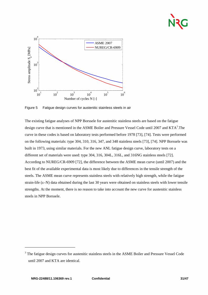
Figure 5 Fatigue design curves for austenitic stainless steels in air
The existing fatigue analyses of NPP Borssele for austenitic stainless steels are based on the fatigue
design curve that is mentioned in the ASME Boiler and Pressure Vessel Code until 2007 and KTA3.The
curve in these codes is based on laboratory tests performed before 1978 [73], [74]. Tests were performed
on the following materials: type 304, 310, 316, 347, and 348 stainless steels [73], [74]. NPP Borssele was
built in 1973, using similar materials. For the new ANL fatigue design curve, laboratory tests on a
different set of materials were used: type 304, 316, 304L, 316L, and 316NG stainless steels [72].
According to NUREG/CR-6909 [72], the difference between the ASME mean curve (until 2007) and the
best fit of the available experimental data is most likely due to differences in the tensile strength of the
steels. The ASME mean curve represents stainless steels with relatively high strength, while the fatigue
strain-life (ε–N) data obtained during the last 30 years were obtained on stainless steels with lower tensile
strengths. At the moment, there is no reason to take into account the new curve for austenitic stainless
steels in NPP Borssele.
3 The fatigue design curves for austenitic stainless steels in the ASME Boiler and Pressure Vessel Code
until 2007 and KTA are identical.
Confidential NRG-22488/11.106369 rev.1 32/47
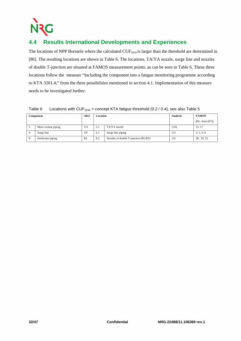
4.4 Results International Developments and Experien ces
The locations of NPP Borssele where the calculated CUF2034 is larger than the threshold are determined in
[86]. The resulting locations are shown in Table 6. The locations, TA/YA nozzle, surge line and nozzles
of double T-junction are situated at FAMOS measurement points, as can be seen in Table 6. These three
locations follow the measure “Including the component into a fatigue monitoring programme according
to KTA 3201.4;” from the three possibilities mentioned in section 4.1. Implementation of this measure
needs to be investigated further.
Table 6 Locations with CUF2034 > concept KTA fatigue threshold (0.2 / 0.4), see also Table 5
Component AKZ Location Analysis FAMOS
(No. from [67])
5 Main coolant piping YA 5.1 TA/YA nozzle {16} 15, 17
6 Surge line YP 6.1 Surge line piping {5} 2, 3, 6, 8
8 Feedwater piping RL 8.2 Nozzles of double T-junction (RL/RS) {4} 28, 29, 32
NRG-22488/11.106369 rev.1 Confidential 33/47
5 Status of Fatigue for 9 Remaining Locations
In this section the status of the 9 remaining locations with respect to crack initiation by fatigue is
presented for the nine locations (six as the outcome of the methodical review and three as the outcome of
environmental fatigue assessment) where at this moment no usage factor can be presented as a value
below the environmental fatigue threshold. For the nine locations it is recommended to perform a new
state of the art fatigue analysis before the end of 2013 in support of LTO (two analyses have currently
been carried out [89],[90]). The assessments in this chapter describe the current fatigue status of these
nine remaining locations. The descriptions in the current chapter are brief and more information on the
assessments can be found in the notes [91],[92],[93],[94],[95],[96],[97] and the report Assessment of
Fatigue TLAAs [85].
Secondary outlet nozzle (steam) (2.8)
A stress calculation of the modified nozzle is present [88]. This analysis shows that the highest stresses
are present at the same location as in the existing fatigue analysis of the original nozzle. Besides this, the
contribution of the thermal transients is low compared to the internal pressure. Therefore, the cumulative
usage factor is not expected to deviate largely from the existing fatigue analysis (0.23 for 2013, ferritic
material) [91]. The conclusion is that no crack initiation is expected for the short term in the RA nozzle
based on the two analyses {26} and [88]. To take into account the current geometry and loading
assumptions, it is recommended to perform a new state of the art fatigue analysis for the RA nozzle of the
steamgenerator.
TA/YA nozzles (5.1)
Based on the projected number of cycles until 2034 and corresponding factors on the partial usage factors
the usage factor for 2034 can be predicted at 0.213 [85]. Exceeding of the environmentally assisted
fatigue awareness threshold will take place in 2029. Therefore no crack initation due to fatigue is
expected before 2029 [92]. To demonstrate fatigue resistance for the entire period of LTO it is
recommended to perform a new state of the art fatigue analysis for the TA/YA nozzle.
TJ/YA nozzle injection (5.2)
No fatigue analysis is available for the TJ/YA nozzle. The measured temperature gradients are very low
(max. 1.0 K/s measured) leading to an allowable number of cycles which is much larger than the
projected number of cycles until 2034 [93]. Based on the measured gradients, no crack initiation is
Confidential NRG-22488/11.106369 rev.1 34/47
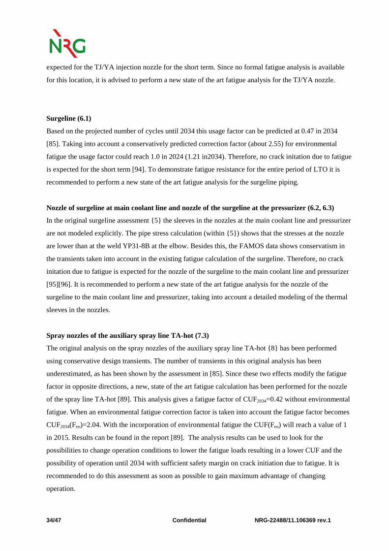
expected for the TJ/YA injection nozzle for the short term. Since no formal fatigue analysis is available
for this location, it is advised to perform a new state of the art fatigue analysis for the TJ/YA nozzle.
Surgeline (6.1)
Based on the projected number of cycles until 2034 this usage factor can be predicted at 0.47 in 2034
[85]. Taking into account a conservatively predicted correction factor (about 2.55) for environmental
fatigue the usage factor could reach 1.0 in 2024 (1.21 in2034). Therefore, no crack initation due to fatigue
is expected for the short term [94]. To demonstrate fatigue resistance for the entire period of LTO it is
recommended to perform a new state of the art fatigue analysis for the surgeline piping.
Nozzle of surgeline at main coolant line and nozzle of the surgeline at the pressurizer (6.2, 6.3)
In the original surgeline assessment {5} the sleeves in the nozzles at the main coolant line and pressurizer
are not modeled explicitly. The pipe stress calculation (within {5}) shows that the stresses at the nozzle
are lower than at the weld YP31-8B at the elbow. Besides this, the FAMOS data shows conservatism in
the transients taken into account in the existing fatigue calculation of the surgeline. Therefore, no crack
initation due to fatigue is expected for the nozzle of the surgeline to the main coolant line and pressurizer
[95][96]. It is recommended to perform a new state of the art fatigue analysis for the nozzle of the
surgeline to the main coolant line and pressurizer, taking into account a detailed modeling of the thermal
sleeves in the nozzles.
Spray nozzles of the auxiliary spray line TA-hot (7.3)
The original analysis on the spray nozzles of the auxiliary spray line TA-hot {8} has been performed
using conservative design transients. The number of transients in this original analysis has been
underestimated, as has been shown by the assessment in [85]. Since these two effects modify the fatigue
factor in opposite directions, a new, state of the art fatigue calculation has been performed for the nozzle
of the spray line TA-hot [89]. This analysis gives a fatigue factor of CUF2034=0.42 without environmental
fatigue. When an environmental fatigue correction factor is taken into account the fatigue factor becomes
CUF2034(Fen)=2.04. With the incorporation of environmental fatigue the CUF(Fen) will reach a value of 1
in 2015. Results can be found in the report [89]. The analysis results can be used to look for the
possibilities to change operation conditions to lower the fatigue loads resulting in a lower CUF and the
possibility of operation until 2034 with sufficient safety margin on crack initiation due to fatigue. It is
recommended to do this assessment as soon as possible to gain maximum advantage of changing
operation.
NRG-22488/11.106369 rev.1 Confidential 35/47
Spray nozzles of the spray lines (7.4)
The original analysis on the spray nozzles of the spray lines {9} has been performed using conservative
design transients. The number of transients in this original analysis has been underestimated, as has been
shown by the assessment in [85]. Since these two effects modify the fatigue factor in opposite directions,
a new, state of the art fatigue calculation has been performed for the nozzle of the main spray lines [90].
This analysis gives a fatigue factor of CUF2034=0.14 without environmental fatigue. When an
environmental fatigue correction factor is taken into account the fatigue factor becomes
CUF2034(Fen)=0.64. Detailed results can be found in the report [90]. The analysis shows no crack initiation
due to fatigue for the period of LTO.
Nozzles of the double T-junction (RL/RS) in the feedwater lines (8.2)
Based on the projected number of cycles until 2034 and including the periodic testing of the feedwater
pumps, this usage factor will reach 0.43 in 2034. Taking into account a conservative value (of 4.83) for
environmental fatigue the usage factor could reach 1.0 in 2015. Therefore no crack initation due to fatigue
can be expected before 2015 [97]. To demonstrate fatigue resistance for the entire period of LTO it is
recommended to perform a new state of the art fatigue analysis for the double T-junction RL/RS.
Confidential NRG-22488/11.106369 rev.1 36/47
6 Conclusions and Recommendations
6.1 Conclusions
In the current report the LTO demonstration of fatigue TLAAs is presented.
First, the scope of fatigue relevant locations is determined. In order to define a complete set of locations
requiring fatigue assessments, a survey is performed independently of the existing fatigue analyses
available in the design documentation of NPP Borssele. The scope is determined by means of criteria,
which are in line with the scoping criteria for the Ageing Management Review (AMR) and the break
preclusion concept. The components and locations are determined based on engineering judgement and
literature on international experience. The components and locations within the scope are subsequently
placed in perspective by a comparison to existing analyses, FAMOS measurement locations, US
regulations and a comparable German NPP.
Then, the locations within the scope are assessed by means of a methodical review. In the review the
loads, calculation methods and component modifications are addressed. Within the review the projected
numbers of load cycles are used to determine a cumulative usage factor representing 2034 (CUF2034). By
this method CUF2034<1 can be determined for all locations except six. It is recommended to perform
further assessment for these locations before the end of 2013 to prove that adequate safety margins
against crack initiation by fatigue are in place also during LTO (two analyses have currently been carried
out [89][90]).
Finally, international experience issues are reviewed. An overview is presented of the different
approaches adopted worldwide (e.g. in the US and Germany) to manage environmentally-assisted fatigue.
For three locations the thresholds for environmentally-assisted fatigue are exceeded. Also, an overview is
given of high-cycle thermal fatigue cracking events at various NPPs in the world. Based on the
information available in the incident reporting and the ageing management database of NPP Borssele, it is
concluded that none of these events is applicable to NPP Borssele. Finally, the applicability of the new
fatigue design curve for austenitic stainless steels (ASME Boiler and Pressure Vessel Code 2009b
Addenda) is discussed. The new fatigue design curve for austenitic stainless steels was derived for a
different set of materials than the fatigue design curve that is mentioned in the ASME Boiler and Pressure
Vessel Code until 2007 and KTA. At the moment, there is no reason to take into account this new curve
for austenitic stainless steels in NPP Borssele.

NRG-22488/11.106369 rev.1 Confidential 37/47
At the moment, for in total nine locations, the usage factor is not available as a value below the
environmental threshold. However, for these locations it is shown that crack initiation due to fatigue is
currently not expected.
With this assessment and the follow-up of the recommendations in the next paragraph a sound basis is
given for the prevention of crack initiation by fatigue for the period of LTO.
6.2 Recommendations
Based on the assessment several recommendations are given for the fatigue TLAAs of NPP Borssele:
• It is recommended to perform further assessment for six locations before the end of 2013 to prove
that adequate safety margins against crack initiation by fatigue are in place also during LTO:
o Secondary outlet nozzle (steam), component location 2.8;
o TJ/YA nozzle injection, component location 5.2;
o Nozzle of surge line at main coolant line, component location 6.2;
o Nozzle of surge line at pressurizer, component location 6.3;
o Spray nozzles of the auxiliary spray line TA-hot, component location 7.3 (see [89]). The
analysis results can be used to look for the possibilities to change operation conditions to
lower the fatigue loads resulting in a lower CUF;
o Spray nozzles of the spray lines, component location 7.4 (see [90]).
• Address environmentally assisted fatigue according to renewed KTA insights in the further
assessment of component locations which have higher usage factors than the threshold. In this
framework, further assessment of three locations is recommended before the end of 2013:
o TA/YA nozzles, component location 5.1;
o Surge line, component location 6.1;
o Nozzles of the double T-junction, component location 8.2.
It is also recommended to use this procedure in the assessment of the six locations mentioned
above;
• Update the load catalogue and load specifications after 5 cycles of FAMOS and revalidate the
fatigue analyses that where required by this update;
• Keep following international developments, in particular high cycle thermal fatigue and
environmentally assisted fatigue.
Confidential NRG-22488/11.106369 rev.1 38/47
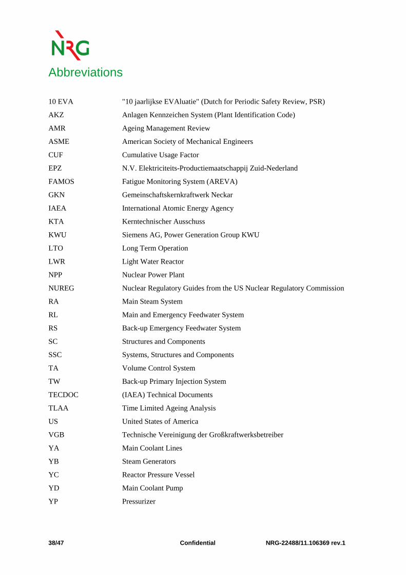
Abbreviations
10 EVA "10 jaarlijkse EVAluatie" (Dutch for Periodic Safety Review, PSR)
AKZ Anlagen Kennzeichen System (Plant Identification Code)
AMR Ageing Management Review
ASME American Society of Mechanical Engineers
CUF Cumulative Usage Factor
EPZ N.V. Elektriciteits-Productiemaatschappij Zuid-Nederland
FAMOS Fatigue Monitoring System (AREVA)
GKN Gemeinschaftskernkraftwerk Neckar
IAEA International Atomic Energy Agency
KTA Kerntechnischer Ausschuss
KWU Siemens AG, Power Generation Group KWU
LTO Long Term Operation
LWR Light Water Reactor
NPP Nuclear Power Plant
NUREG Nuclear Regulatory Guides from the US Nuclear Regulatory Commission
RA Main Steam System
RL Main and Emergency Feedwater System
RS Back-up Emergency Feedwater System
SC Structures and Components
SSC Systems, Structures and Components
TA Volume Control System
TW Back-up Primary Injection System
TECDOC (IAEA) Technical Documents
TLAA Time Limited Ageing Analysis
US United States of America
VGB Technische Vereinigung der Großkraftwerksbetreiber
YA Main Coolant Lines
YB Steam Generators
YC Reactor Pressure Vessel
YD Main Coolant Pump
YP Pressurizer